anexo j fia 2012
TRANSCRIPT
1© 2012 Federación Internacional del Automóvil
Appendix J to the International Sporting CodeArt. 251 Classification and Definitions of Cars .......................................................................................................3Art. 252 General Prescriptions for Production Cars (Group N), Touring Cars (Group A), Grand Touring Cars (Group B)..................................................................................................................9Art. 253 Safety Equipment (Groups N, A ............................................................................................................. 15Art. 254 Specific Regulations for Production Cars (Groupe N) .......................................................................... 28Art. 254A Specific Regulations for Super 2000 - Rallies ....................................................................................... 39Art. 255 Specific Regulations for Touring Cars (Groupe A) ................................................................................ 51Art. 255A Specific Regulations for Super 2000 Rallies / WRC ............................................................................. 68Art. 256 Specific Regulations for GT Production Cars (Group RGT) ................................................................. 81Art. 257A Technical Regulations for Cup Grand Touring Cars (Group GT3) ....................................................... 90Art. 259 Technical Regulations for Production Sports Cars (Groupe CN) ........................................................ 98Art. 260 Specific Regulations for Cars in Groups R ...........................................................................................114Art. 260D Regulations for R3D and R3T Cars ......................................................................................................115Art. 263 Specific Regulations for Super 2000 (Modified Production Cars) on Circuits ....................................116Art. 275 Formula 3 Technical Regulations ........................................................................................................ 134Art. 277 Free Formula Technical Regulations (Group E).................................................................................. 180Art. 278 National Formulae Technical Regulations .......................................................................................... 188Art. 279 Technical Regulations for Rallycross and Autocross Cars ................................................................. 189Art. 281 Classification and Definitions of Cross-Country Vehicles .................................................................. 210Art. 282 General Prescriptions for Cross-Country Vehicles ............................................................................. 216Art. 283 Safety Equipment for Cross-Country Vehicles ................................................................................... 221Art. 284 Specific Regulations for Series Cross-Country Cars (Group T2) ....................................................... 236Art. 285 Specific Regulations for Modified Cross-Country Cars (Group T1) ................................................... 243Art. 286 Specific Regulations for Improved Cross-Country Cars (Group T3) .................................................. 252Art. 287 Cross-Country Trucks Technical Regulations (Group T4) .................................................................. 260Art. 290 Racing Trucks Technical Regulations (Group F)................................................................................. 268Drawings ................................................................................................................................................................. 286Technical Lists ....................................................................................................................................................... 311List of FIA homologated vehicles and engines ................................................................................................. 312
Anexo J al Código Deportivo InternacionalArt. 251 Clasificación y definiciones de los Vehículos ...........................................................................................3Art. 252 Prescripciones generales para los Vehículos de Producción (Grupo N),
Vehículos de Turismo (Grupo A) y Vehículos de Gran Turismo (Grupo B) .............................................9Art. 253 Equipamiento de Seguridad (Grupos N y A) ......................................................................................... 15Art. 254 Reglamento Específico para Vehículos de Producción (Grupo N) ...................................................... 28Art. 254A Reglamento Específico para Vehículos Súper 2000 - Rallyes ............................................................. 39Art. 255 Reglamento Específico para Vehículos de Turismo (Grupo A) ............................................................ 51Art. 255A Reglamento Específico para Vehículos Súper 2000 Rallyes / WRC ................................................... 68Art. 256 Reglamento Específico para Vehículos GT de Producción (Grupo RGT) ........................................... 81Art. 257A Reglamento Técnico para Vehículos de Gran Turismo «Cup» (Grupo GT3) ...................................... 90Art. 259 Reglamento Técnico para Vehículos de Producción Sport (Grupo CN) .............................................. 98Art. 260 Reglamento Específico para Vehículos de los Grupos R ...................................................................114Art. 260D Reglamento para Vehículos R3D y R3T ..............................................................................................115Art. 263 Reglamento Específico para Vehículos Súper 2000 (Vehículos de Producción Modificados) en
Circuitos .................................................................................................................................................116Art. 275 Reglamento Técnico para Fórmula 3 .................................................................................................. 134Art. 277 Reglamento Técnico para Fórmula Libre (Grupo E) .......................................................................... 180Art. 278 Reglamento Técnico para Fórmulas Nacionales ................................................................................ 188Art. 279 Reglamento Técnico para Vehículos de Rallycross y de Autocross .................................................. 189Art. 281 Clasificación y definiciones de Vehículos Todo Terreno ..................................................................... 210Art. 282 Prescripciones Generales para los Vehículos Todo Terreno .............................................................. 216Art. 283 Equipamiento de seguridad para Vehículos Todo Terreno ................................................................. 221Art. 284 Reglamento Específico para Vehículos Todo Terreno de Serie (Grupo T2) ...................................... 236Art. 285 Reglamento Específico para Vehículos Todo Terreno Modificados (Grupo T1) ................................ 243Art. 286 Reglamento Específico para Vehículos Todo Terreno Mejorados (Grupo T3) .................................. 252Art. 287 Reglamento Técnico para Camiones Todo Terreno (Grupo T4) ........................................................ 260Art. 290 Reglamento Técnico para Camiones de Competición (Grupo F) ...........................................................268Dibujos .................................................................................................................................................................... 286Listas Técnicas ....................................................................................................................................................... 311Lista de Vehículos y Motores Homologados por la FIA ................................................................................... 312
2
Nota: En caso de diferencias de interpretación entre los términos de diversas traducciones de los reglamentos oficiales de la FIA, solo el texto en francés dará fe (salvo indicación en contrario).
LOS TEXTOS DE LOS DIFERENTES REGLAMENTOS PREPARADOS POR LA FIA (Código Deportivo Internacional y sus Anexos y Reglamentos de los Campeonatos Internacionales de la FIA) QUE FIGURAN EN ESTE ANUARIO SON LOS REDACTADOS AL 15 DE DICIEMBRE DE 2011.
TODAS LAS MODIFICACIONES SERÁN PUBLICADAS, A PARTIR DE ESTA FECHA, EN EL BOLETÍN OFICIAL DE LA FIA (salvo las Listas Técnicas y la Lista de Vehículos Homologados, que serán publicadas en el sitio web de la FIA, www.fia.com).
Note: In the case of differences of interpretation as regards the terms used in the various translations of official FIA regulations, only the French text will be considered authentic (unless otherwise stated).
TEXTS OF THE VARIOUS REGULATIONS DRAFTED BY THE FIA (International Sporting Code and its Appendices and Regulations of the FIA International Championships) APPEARING IN THIS YEARBOOK ARE THOSE DRAWN UP ON 15 DECEMBER 2011.
ANY AMENDMENTS WILL BE PUBLISHED AFTER THIS DATE IN THE FIA OFFICIAL BULLETIN (except for the Technical Lists and the List of Homologated Vehicles, which will be posted on the FIA Website - www.fia.com).
3
ARTÍCULO 1 - CLASIFICACIÓN1.1 Categorías y grupos
Los vehículos utilizados en competición se dividirán en las siguientes categorías y grupos:Categoría I:- Grupo N: Vehículos de Producción.- Grupo A: Vehículos de Turismo- Grupo R: Vehículos de Turismo o de Gran Producción en
SerieCategoría II:- Grupo RGT: Vehículos GT y de Producción- Grupo GT1: Vehículos de Gran Turismo.- Grupo GT2: Vehículos de Gran Turismo.- Grupo GT3: Vehículos Gran Turismo «Cup»- Grupo CN: Vehículos de Producción Sport- Grupo D: Vehículos de Competición de Fórmula
Internacional.- Grupo E: Vehículos de Competición de Fórmula Libre.
Categoría III:- Grupo F: Camiones de Competición.
1.2 Clases por cilindradaLos vehículos se dividirán en las siguientes clases en función de su cilindrada:1. Hasta 500 cm3
2. Más de 500 cm3 hasta 600 cm3
3. Más de 600 cm3 hasta 700 cm3
4. Más de 700 cm3 hasta 850 cm3
5. Más de 850 cm3 hasta 1.000 cm3
6. Más de 1.000 cm3 hasta 1.150 cm3
7. Más de 1.150 cm3 hasta 1.400 cm3
8. Más de 1.400 cm3 hasta 1.600 cm3
9. Más de 1.600 cm3 hasta 2.000 cm3
10. Más de 2.000 cm3 hasta 2.500 cm3
11. Más de 2.500 cm3 hasta 3.000 cm3
12. Más de 3.000 cm3 hasta 3.500 cm3
13. Más de 3.500 cm3 hasta 4.000 cm3
14. Más de 4.000 cm3 hasta 4.500 cm3
15. Más de 4.500 cm3 hasta 5.000 cm3
16. Más de 5.000 cm3 hasta 5.500 cm3
17. Más de 5500 cm3 hasta 6000 cm3
18. Más de 6000 cm3
Salvo disposiciones contrarias, eventualmente impuestas por la FIA para una categoría de pruebas determinada, los organizadores no están obligados a incluir todas las clases en los reglamentos particulares y, además, son libres de agrupar dos o más clases consecutivas, de acuerdo con las circunstancias particulares de sus pruebas. Ninguna clase podrá ser subdividida.
ARTÍCULO 2 - DEFINICIONES2.1 Generalidades2.1.1) Vehículos de Producción en Serie (Categoría I):
Vehículos de los que se ha comprobado, a instancias del constructor, la fabricación en serie de cierto número de ejemplares idénticos (ver definición de esta palabra más adelante) en cierto período de tiempo, y que están destinados a la venta normal al público (ver esta expresión). Los vehículos deberán venderse de conformidad con la ficha de homologación.
2.1.2) Vehículos de Competición (Categoría II):Vehículos construidos a la unidad y destinados exclusivamente a la competición.
2.1.3) Camiones (Categoría III).2.1.4) Vehículos idénticos:
Vehículos pertenecientes a una misma serie de fabricación y que tienen la misma carrocería (exterior e interior), los mismos componentes mecánicos y el mismo chasis (incluso aunque este chasis pudiera ser una parte integrante de la carrocería en una construcción monocasco).
2.1.5) Modelo de vehículo:Vehículo perteneciente a una serie de fabricación que se
ARTÍCULO 251CLASIFICACIÓN Y DEFINICIONES DE LOS VEHÍCULOS /
CLASSIFICATION AND DEFINITIONS OF CARS
ARTICLE 1 - CLASSIFICATION1.1 Categories and groups
The cars used in competition shall be divided up into the following categories and groups:Category I:- Group N: Production Cars- Group A: Touring Cars- Group R: Touring Cars or Large Scale Series Production
Cars
Category II:- Group RGT: GT Production Cars- Group GT1: Grand Touring Cars- Group GT2: Grand Touring Cars- Group GT3: Cup Grand Touring Cars- Group CN: Production Sports Cars- Group D: International Formula Racing Cars- Group E: Free Formula Racing Cars
Category III:- Group F: Racing Trucks
1.2 Cubic capacity classesThe cars will be divided up into the following classes according to their cubic capacity:1. up to 500 cm3
2. over 500 cm3 and up to 600 cm3
3. over 600 cm3 and up to 700 cm3
4. over 700 cm3 and up to 850 cm3
5. over 850 cm3 and up to 1.000 cm3
6. over 1000 cm3 and up to 1.150 cm3
7. over 1150 cm3 and up to 1.400 cm3
8. over 1400 cm3 and up to 1.600 cm3
9. over 1600 cm3 and up to 2.000 cm3
10. over 2000 cm3 and up to 2.500 cm3
11. over 2500 cm3 and up to 3.000 cm3
12. over 3000 cm3 and up to 3.500 cm3
13. over 3500 cm3 and up to 4.000 cm3
14. over 4000 cm3 and up to 4.500 cm3
15. over 4500 cm3 and up to 5.000 cm3
16. over 5000 cm3 and up to 5.500 cm3
17. over 5500 cm3 and up to 6000 cm3
18. over 6000 cm3
Unless otherwise specified in special provisions imposed by the FIA for a certain category of events, the organisers are not bound to include all the above-mentioned classes in the Supplementary Regulations and, furthermore, they are free to group two or more consecutive classes, according to the particular circumstances of their events. No Class can be subdivided.
ARTICLE 2 - DEFINITIONS2.1 General conditions2.1.1) Series Production cars (Category I):
Cars of which the production of a certain number of identical examples (see definition of this word hereinafter) within a certain period of time has been verified at the request of the manufacturer, and which are destined for normal sale to the public (see this expression). Cars must be sold in accordance with the homologation form.
2.1.2) Competition cars (Category II):Cars built as single examples and destined solely for competition.
2.1.3) Trucks (Category III)2.1.4) Identical cars:
Cars belonging to the same production series and which have the same bodywork (outside and inside), same mechanical components and same chassis (even though this chassis may be an integral part of the bodywork in case of a monocoque construction).
2.1.5) Model of car:Car belonging to a production-series distinguishable by a specific
4
ANEXO «J» - DEFINICIONESAPPENDIX “J” - DEFINITIONS
distingue por una concepción y una línea exterior de la carrocería determinadas, y por una misma ejecución mecánica del motor y de la transmisión a las ruedas.
2.1.6) Venta normal:Significa la distribución de los vehículos a los clientes individuales a través del servicio comercial del constructor.
2.1.7) Homologación:Es la certificación oficial hecha por la FIA de que un modelo de vehículo determinado ha sido fabricado en serie en un número suficiente para ser clasificado en Vehículos de Producción (Grupo N) o Vehículos de Turismo (Grupo A) del presente reglamento.La solicitud de homologación debe ser enviada a la FIA por la ADN del país de construcción del vehículo y dará lugar al establecimiento de una ficha de homologación (ver a continuación).Deberá estar hecha de acuerdo con un reglamento especial llamado «Reglamento de Homologación», redactado por la FIA.Toda homologación de un modelo fabricado en serie caducará a los 7 años del cese definitivo de la fabricación en serie de dicho modelo (producción anual inferior al 10% del mínimo de producción del grupo considerado).La homologación de un modelo solo puede ser válida en un grupo, Vehículos de Producción (Grupo N)/ Vehículos de Turismo (Grupo A).
2.1.8) Fichas de homologación:Todo modelo de vehículo homologado por la FIA será objeto de una ficha descriptiva llamada «ficha de homologación», en la que figurarán todas las características que permitan identificar a dicho modelo. Esta ficha de homologación define la serie tal y como la indica el fabricante.Según el grupo en el que el participante compita, los límites de las modificaciones autorizadas en competiciones internacionales con relación a esta serie están indicadas en el Anexo J.La presentación de las fichas en las verificaciones y/o antes de la salida podrá ser exigida por los organizadores con derecho a rehusar la participación del concursante en caso de no presentación.La ficha de homologación debe estar obligatoriamente impresa:- - en papel estampado o con marca de agua de la FIA- o en papel estampado o con marca de agua de una ADN
únicamente en el caso en el que el constructor sea de la misma nacionalidad que la ADN.
Asimismo, en caso de utilización de un vehículo de Grupo A equipado con una Variante Kit (ver a continuación) que afecte al chasis/carrocería, debe presentarse un certificado original suministrado por un centro de montaje aprobado por el constructor.Si la fecha de entrada en vigor de una ficha de homologación se sitúa durante una prueba, esa ficha será válida para esta prueba durante toda su duración.En lo que se refiere a Vehículos de Producción (Grupo N), además de la ficha específica para este grupo, debe presentarse igualmente la ficha de Vehículos de Turismo (Grupo A).En el caso de que durante la verificación de un modelo de vehículo con su ficha de homologación apareciera cualquier duda, los comisarios técnicos deberían recurrir al manual de mantenimiento editado para uso de los concesionarios de la marca o bien al catálogo general en el que aparece el listado de piezas de recambio.En el caso de que esta documentación no fuera suficientemente precisa, será posible efectuar verificaciones directas por comparación con una pieza idéntica, disponible en un concesionario.Es deber del concursante proveerse de la ficha de homologación de su vehículo en su ADN.Description: Una ficha se compone de lo siguiente:
1) Una ficha base en la que se describe el modelo base.2) En los casos en que corresponda, un cierto número de hojas
suplementarias en las que se describan las extensiones de homologación, que pueden ser «variantes», «erratas» o «evoluciones».
a) Variantes (VF, VP, VO, VK)Son Variantes de Suministro (VF) (dos fabricantes diferentes suministran al constructor una misma pieza, y el cliente no tiene la posibilidad de elegir), Variantes de Producción (VP) (entregadas a pedido y disponibles en los concesionarios),
conception and external general lines of the bodywork and by an identical mechanical construction of the engine and the transmission to the wheels.
2.1.6) Normal sale:Means the distribution of cars to individual purchasers through the normal commercial channels of the manufacturer.
2.1.7) Homologation:Is the official certification made by the FIA that a minimum number of cars of a specific model has been made on series-production terms to justify classification in Production Cars (Group N), Touring Cars (Group A) of these regulations.Application for homologation shall be submitted to the FIA by the ASN of the country in which the vehicle is manufactured and shall entail the drawing up of a homologation form (see below).It must be established in accordance with the special regulations called "Homologation Regulations", laid down by the FIA. Homologation of a series-produced car will become null and void 7 years after the date on which the series-production of the said model has been stopped (series-production under 10 % of the minimum production of the group considered).The homologation of a model can only be valid in one group, Production Cars (Group N) / Touring Cars (Group A).
2.1.8) Homologation forms:All cars recognised by the FIA will be the subject of a descriptive form called "Homologation Form" on which shall be entered all data enabling identification of the said model.This homologation form defines the series as indicated by the manufacturer.According to the group in which the competitors race, the modification limits allowed in international competition for the series are stated in Appendix J. The presentation of the forms at scrutineering and/or at the start may be required by the organisers who will be entitled to refuse the participation of the entrant in the event in case of non-presentation.The form presented must imperatively be printed:- Either on FIA stamped/watermarked paper- Or on stamped/watermarked paper from an ASN only if the
manufacturer is of the same nationality as the ASN concerned.
Likewise, if a Group A car fitted with a kit variant (see below) concerning the chassis/shell is used, the original certificate supplied at the time of mounting by a centre approved by the manufacturer must be presented.Should the date for the coming into force of a homologation form fall during an event, this form will be valid for that event throughout the duration of the said event.With regard to Production Cars (Group N), apart from the specific form for this group, the Touring Cars (Group A) form must also be submitted.In case of any doubt remaining after the checking of a model of car against its homologation form, the Scrutineers should refer either to the maintenance booklet published for the use of the make’s distributors or to the general catalogue in which are listed all spare parts.In case of lack of sufficient accurate documentation, Scrutineers may carry out direct scrutineering by comparison with an identical part available from a concessionaire.
It will be up to the competitor to obtain the homologation form concerning his car from his ASN.
Description: A form breaks down in the following way:
1) A basic form giving a description of the basic model.2) At a later stage, a certain number of additional sheets describing
"homologation extensions", which can be "variants", or "errata" or "evolutions".
a) Variants (VF, VP, VO, VK)These are either supply variants (VF) (two suppliers providing the same part for the manufacturer and the client does not have the possibility of choice), or production variants (VP) (supplied on request and available from dealers), or option variants (VO)
5
ANEXO «J» - DEFINICIONESAPPENDIX “J” - DEFINITIONS
Variantes Opción (VO) (entregadas por pedido específico) o «Kits» (VK) (suministradas por pedido específico).
b) Erratas (ER)Sustituyen y cancelan una información errónea incluida anteriormente en una ficha por el fabricante.
c) Evolución (ET)Caracteriza a las modificaciones aportadas de forma definitiva al modelo base (abandono total de la fabricación del modelo en su forma original).Utilización:
1) Variantes (VF, VP, VO, VK):El concursante podrá utilizar a su conveniencia cualquier variante o parte de una variante, a condición de que todos los datos técnicos del vehículo así concebido estén conformes con los que se describen en la ficha de homologación aplicable al vehículo, o expresamente autorizados en el AnexoJ.La combinación de varias VO sobre los elementos siguientes está prohibida: turbocompresor, frenos y caja de cambios.Por ejemplo, el montaje de una pinza de freno definida en una ficha variante solo es posible si las dimensiones de las pastillas y otras piezas así obtenidas están indicadas en una ficha aplicable al vehículo de que se trate. (Ver también el Artículo 254-2 para Vehículos de Producción - Grupo N).En lo referente a las Variantes Kit, no podrán utilizarse nada más que en las condiciones que indique el constructor en la ficha de homologación.Esto afecta particularmente a los grupos de piezas que deben ser consideradas obligatoriamente como un conjunto por el concursante, y a las especificaciones que eventualmente deben respetarse.Para los Campeonatos de la FIA, el Pasaporte Técnico FIA de los vehículos WRC, S2000- Rallyes, S2000 y Súper 1600 debe ser presentado al momento de las verificaciones técnicas de la prueba.Además, las marcas que guarden relación con el pasaporte técnico no deben ser quitadas bajo ninguna circunstancia.
2) Evolución de tipo (ET):(Ver también el Artículo 254-2 para Vehículos de Producción [Grupo N]).El vehículo debe corresponder a un estado de evolución determinado (independientemente de su fecha real de salida de la fábrica) y, por consiguiente, una evolución debe ser aplicada íntegramente o no debe ser aplicada en absoluto.Además, a partir del momento en que el concursante haya elegido una evolución concreta, todas las anteriores han de ser igualmente aplicadas, salvo si existe incompatibilidad entre ellas.Por ejemplo, si dos evoluciones en los frenos han ocurrido sucesivamente, se utilizará solamente la que corresponda, por la fecha, al estado de evolución del vehículo.
2.1.9) Componentes mecánicos:Todos aquellos necesarios para la propulsión, suspensión, dirección y frenado, así como todos los accesorios, móviles o no, que son necesarios para su funcionamiento normal.
2.1.10) Piezas de origen o de serie:Una pieza que ha sufrido todas las etapas de producción previstas y efectuadas por el constructor del vehículo considerado, y montada de origen en el vehículo.
2.1.11) Material compuesto:Material formado por varios componentes distintos, cuya asociación proporciona al conjunto unas propiedades que no posee ninguno de los componentes por separado.
2.1.12) Materiales–Definiciones:Aleación a base de X (por ejemplo, aleación a base de Ni) – X debe ser el elemento más abundante de la aleación sobre una base % w/w. El porcentaje de masa mínima del elemento X debe ser siempre superior al porcentaje máximo de cada uno de los otros elementos presentes en la aleación.
2.2 DimensionesPerímetro del vehículo visto desde arriba: Como se presenta el vehículo en la parrilla de salida para la prueba en cuestión.
2.3 Motor2.3.1) Cilindrada:
Volumen V engendrado en el cilindro (o cilindros) por el movimiento ascendente o descendente del pistón(es).
(supplied on specific request), or "kits" (VK) (supplied on specific request).
b) Erratum (ER)Replaces and cancels an incorrect piece of information previously supplied by the constructor on a form.
c) Evolution (ET)Characterises modifications made on a permanent basis to the basic model (complete cessation of the production of the car in its original form.Use:
1) Variants (VF, VP, VO, VK)The competitor may use any variant or any article of a variant as he wishes, only on condition that all the technical data of the vehicle, so designed, conforms to that described on the homologation form applicable to the car, or expressly allowed by Appendix J. The combination of several VOs on the following parts is prohibited: Turbocharger, brakes and gearbox.For example, the fitting of a brake caliper as defined on a variant form is only possible if the dimensions of the brake linings, etc. obtained in this way, are indicated on a form applicable to the car in question. (For Production Cars (Group N), see also Art. 254-2).
As far as kit-variants (VK) are concerned, they may not be used only under the conditions indicated by the manufacturer on the homologation form.This concerns in particular those groups of parts which must be considered as a whole by the competitor, and the specifications which are to be respected, if applicable.
For FIA Championships, the FIA Technical Passport of WRC, S2000-Rally, S2000 and Super 1600 cars must be presented at scrutineering for the event.In addition, the markings linked to the technical passport must not be removed under any circumstances.
2) Evolution of the type (ET)(For Production Cars - Group N, see also Art. 254-2)The car must comply with a given stage of evolution (independent of the date when it left the factory), and thus an evolution must be wholly applied or not at all.Besides, from the moment a competitor has chosen a particular evolution, all the previous evolutions should be applied, except where they are incompatible.For example, if two brake evolutions happen one after another, only that corresponding to the date of the stage of evolution of the car will be used.
2.1.9) Mechanical components:All those necessary for the propulsion, suspension, steering and braking as well as all accessories whether moving or not which are necessary for their normal working.
2.1.10) Original or series parts:A part which has undergone all the stages of production foreseen and carried out by the manufacturer of the vehicle concerned, and originally fitted on the vehicle.
2.1.11) Composite:Material formed from several distinct components, the association of which provides the whole with properties which none of the components taken separately possesses.
2.1.12) Materials–Definitions:X Based Alloy (e.g. Ni based alloy) – X must be the most abundant element in the alloy on a % w/w basis. The minimum possible weight percent of the element X must always be greater than the maximum possible of each of the other individual elements present in the alloy.
2.2 DimensionsPerimeter of the car seen from above: The car as presented on the starting grid for the event in question.
2.3 Engine
2.3.1) Cylinder capacity:Volume V generated in cylinder (or cylinders) by the upward or downward movement of the piston(s).
6
ANEXO «J» - DEFINICIONESAPPENDIX “J” - DEFINITIONS
V = 0,7854 x d2 x c x nDonde: d = diámetro de cilindros
c = carreran = cantidad de cilindros
2.3.2) Sobrealimentación:Aumento de la presión de la carga de la mezcla aire-combustible en la cámara de combustión (con relación a la presión engendrada por la presión atmosférica normal, el efecto de inercia y los efectos dinámicos en los sistemas de admisión y/o escape) por cualquier medio, sea cual fuere.La inyección de combustible a presión no se considera sobrealimentación (ver Artículo 252-3.1 de las Prescripciones Generales).
2.3.3) Bloque motor:El cárter del cigüeñal y los cilindros.
2.3.4) Colector de admisión:En el caso de un sistema de alimentación por carburador:- Pieza que recoge la mezcla aire-combustible a la salida
del(los) carburador(es) y que llega hasta el plano de la junta con la culata.
En el caso de un sistema de alimentación de inyección con una sola mariposa:- Pieza que se extiende desde el cuerpo de la mariposa,
inclusive, hasta el plano de la junta con la culata, y se utiliza para recoger y regular el flujo del aire o de la mezcla aire-combustible.
En el caso de un sistema de alimentación de inyección con mariposas múltiples:- Pieza que se extiende desde las mariposas, inclusive, hasta
el plano de la junta con la culata, y se utiliza para recoger y regular el flujo de aire o de la mezcla aire-combustible.
En el caso de un motor diésel:- Sistema fijado a la culata, que distribuye el aire desde una
entrada de aire o un conducto único hasta los orificios de la culata.
2.3.5) Colector de escape:Pieza que recoge en todo momento los gases de al menos dos cilindros desde la culata y llega hasta la primera junta que lo separa del resto del sistema de escape.
2.3.6) Para los vehículos con turbocompresor, el escape comienza después del turbocompresor.
2.3.7) Cárter de aceite:Los elementos atornillados al bloque motor por debajo que contienen y controlan el aceite de lubricación del motor.
2.3.8) Compartimento motor:Volumen definido por la envoltura estructural más próxima al motor.
2.3.9) Lubricación por cárter seco:Todo sistema que utiliza una bomba para transferir aceite de una cámara o compartimento a otro, con exclusión de la bomba utilizada únicamente para la lubricación normal de las piezas del motor.
2.3.10) Junta estática para piezas mecánicas:La única función de una junta es asegurar la estanqueidad de al menos dos piezas, unidas una con la otra.La distancia entre las caras de las piezas separadas por la junta debe ser menor o igual a 5 mm.
2.3.11) Intercambiador:Elemento mecánico que permite el intercambio de calorías entre dos fluidos.Para los intercambiadores específicos, el fluido nombrado en primer lugar es el fluido que debe ser refrigerado, y el fluido nombrado en segundo lugar es el fluido que permite la refrigeración.Ejemplo: Intercambiador aceite/agua (el aceite es refrigerado por el agua).
2.3.12) Radiador:Es el intercambiador específico que permite refrigerar un líquido por medio del aire. Intercambiador líquido/aire.
2.3.13) Intercooler o intercambiador de sobrealimentación:Es un intercambiador, situado entre el compresor y el motor, que permite refrigerar el aire comprimido por medio de un fluido. Intercambiador aire/fluido.
2.4 Tren rodante
V = 0.7854 x b2 x s x nwhere: b) = bore
s = stroken = number of cylinders
2.3.2) Supercharging:Increasing the weight of the charge of the fuel-air mixture in the combustion chamber (over the weight induced by normal atmospheric pressure, ram effect and dynamic effects in the intake and/or exhaust systems) by any means whatsoever.
The injection of fuel under pressure is not considered to be supercharging (see Article 252-3.1 of the General Prescriptions).
2.3.3) Cylinder block:The crankcase and the cylinders.
2.3.4) Intake manifold:In the case of a carburettor induction system :- Part collecting the air-fuel mixture from the carburettor(s) and
extending to the cylinder head gasket face.
In the case of a single-valve injection induction system :- Part extending from the body of the butterfly valve inclusive to
the cylinder head gasket face, collecting and regulating the air or the air-fuel mixture flow.
In the case of a multi-valve injection induction system :- Part extending from the butterfly valves inclusive to the
cylinder head gasket face, collecting and regulating the air or the air-fuel mixture flow.
In the case of a diesel engine :
- Unit mounted to the cylinder head, which distributes the air from one inlet or a sole duct to the cylinder head ports.
2.3.5) Exhaust manifold:Part collecting together at any time the gases from at least two cylinders from the cylinder head and extending to the first gasket separating it from the rest of the exhaust system.
2.3.6) For cars with a turbocharger, the exhaust begins after the turbocharger.
2.3.7) Sump: The elements bolted below and to the cylinder block which contain and control the lubricating oil of the engine.
2.3.8) Engine compartment: Volume defined by the structural envelope closest to the engine.
2.3.9) Lubrication by dry sump:Any system using a pump to transfer oil from one chamber or compartment to another, to the exclusion of the pump used for the normal lubrication of the engine parts.
2.3.10) Static gasket for mechanical partsThe only function of a gasket is to ensure the sealing of at least two parts, fixed in relation to each other.The distance between the faces of the parts separated by the gasket must be less than or equal to 5 mm.
2.3.11) Exchanger:Mechanical part allowing the exchange of calories between two fluids.For specific exchangers, the first-named fluid is the fluid to be cooled and the second-named fluid is the fluid that allows this cooling.e.g. Oil/Water Exchanger (the oil is cooled by the water).
2.3.12) Radiator:This is a specific exchanger allowing liquid to be cooled by air. Liquid / Air Exchanger.
2.3.13) Intercooler or Supercharging Exchanger:This is an exchanger, situated between the compressor and the engine, allowing the compressed air to be cooled by a fluid. Air / Fluid Exchanger.
2.4 Running gear
7
ANEXO «J» - DEFINICIONESAPPENDIX “J” - DEFINITIONS
El tren rodante incluye todos los elementos total o parcialmente no suspendidos.
2.4.1) Rueda:El disco y la llanta. Por rueda completa se entiende disco, llanta y neumático.
2.4.2) Superficiederozamientodelosfrenos:Superficie barrida por las zapatas del tambor, o las pastillas en ambos lados del disco cuando la rueda describe una vuelta completa.
2.4.3) Suspensión McPherson:Todo sistema de suspensión en el que un elemento telescópico, que no necesariamente cumple la función de amortiguación y/o suspensión, pero que incluye el vástago, que está fijado en su parte superior sobre un solo punto de anclaje solidario con la carrocería (o el chasis) y pivota en su parte inferior sobre un brazo transversal que asegura el guiado transversal y longitudinal, o sobre un único brazo transversal mantenido longitudinalmente por una barra estabilizadora o una bieleta de triangulación.
2.4.4) Eje semitorsional:Eje constituido por dos brazos tirados longitudinales unidos al monocasco por una articulación y entre sí rígidamente por un perfil transversal cuya rigidez a la torsión es pequeña comparada con su rigidez a la flexión.
2.5 Chasis y carrocería2.5.1) Chasis:
Estructura de conjunto del vehículo alrededor de la cual se montan los elementos mecánicos y la carrocería, y que incluye cualquier pieza solidaria de dicha estructura.
2.5.2) Carrocería:- Exteriormente: Todas las partes enteramente suspendidas del
vehículo lamidas por la corriente de aire.- Interiormente: El habitáculo y el maletero.Conviene distinguir los grupos siguientes de carrocerías:
1) Carrocería completamente cerrada.2) Carrocería completamente abierta.3) carrocería transformable: con capota flexible, rígida, maniobrable
o deslizante.2.5.3) Asiento:
Las dos superficies que forman la banqueta del asiento y el respaldo.Respaldo: La superficie medida desde la parte inferior de la columna vertebral de una persona normalmente sentada, hacia arriba.Banqueta del asiento: La superficie medida desde la parte inferior de la columna vertebral de esta misma persona hacia delante.
2.5.4) Maletero:Todo volumen distinto del habitáculo y del compartimento motor y situado en el interior de la estructura del vehículo.Este volumen está limitado, en longitud, por las estructuras fijas previstas por el constructor y/o por la cara posterior de los asientos traseros en su posición más atrasada y/o, si fuera posible, reclinado un ángulo máximo de 15º hacia atrás.Este volumen está limitado en altura por las estructuras fijas y/o las separaciones móviles previstas por el constructor, o en su defecto, por el plano horizontal que pasa por el punto más bajo del parabrisas.
2.5.5) Habitáculo:Volumen estructural interior en el que sitúan el piloto y los pasajeros.
2.5.6) Capó-motor:Parte exterior de la carrocería que se abre para dar acceso al motor.
2.5.7) Aleta:Una aleta es la parte definida según el Dibujo 251-1.
Aleta delantera: Parte recorrida por la corriente de aire, limitada por la cara interior de la rueda completa del vehículo estándar (C1/C1), el borde delantero de la puerta delantera (B1/B1), y situada por debajo del plano paralelo al borde superior de la puerta y tangente a las esquinas inferiores de la parte visible del parabrisas (A1/A1).Aleta trasera: Parte recorrida por la corriente de aire, limitada por
The running gear includes all parts totally or partially unsuspended.
2.4.1) Wheel:Flange and rim. By complete wheel is meant flange, rim and tyre.
2.4.2) Friction surface of the brakes:Surface swept by the linings on the drum, or the pads on both sides of the disc when the wheel achieves a complete revolution.
2.4.3) Mac Pherson suspension:Any suspension system in which a telescopic strut, not necessarily providing the springing and/or damping action, but incorporating the stub axle, is anchored on the body or chassis through single attachment point at its top end, and pivots at its bottom end either on a transverse wishbone locating it transversally and longitudinally, or on a single transverse link located longitudinally by an anti-roll bar, or by a tie rod.
2.4.4) Twist beam axle :Axle made of two longitudinal trailing arms, each attached to the bodyshell through a joint, and rigidly attached one to the other through a transverse structure, the torsion stiffness of which is low compared to its bending stiffness.
2.5 Chassis - Bodywork2.5.1) Chassis:
The overall structure of the car around which are assembled the mechanical components and the bodywork including any structural part of the said structure.
2.5.2) Bodywork:- externally: all the entirely suspended parts of the car licked by
the airstream.- internally: cockpit and boot.Bodywork is differentiated as follows:
1) completely closed bodywork2) completely open bodywork3) convertible bodywork with the hood in either supple (drop-head)
or rigid (hardtop) material.2.5.3) Seat:
The two surfaces making up the seat cushion and seatback or backrest.Seatback or backrest: Surface measured from the bottom of a normally seated person’s spine.Seat cushion: Surface measured from the bottom of the same person’s spine towards the front.
2.5.4) Luggage compartment:Any volume distinct from the cockpit and the engine compartment inside the vehicle.These volumes are limited in length by the fixed structures provided for by the manufacturer and/or by the rear of the seats and/or, if this is possible, reclined at a maximum angle of 15° to the rear.These volumes are limited in height by the fixed structures and/or by the detachable partitions provided for by the manufacturer, or in the absence of these, by the horizontal plane passing through the lowest point of the windscreen.
2.5.5) Cockpit:Structural inner volume which accommodates the driver and the passengers.
2.5.6) Bonnet:Outer part of the bodywork which opens to give access to the engine.
2.5.7) Mudguard:A mudguard will be considered to be the area defined according to Drawing 251-1.Front mudguard: The area licked by the airstream, defined by the inner face of the complete wheel of the standard car (C1/C1), the front edge of the front door (B1/B1), and situated below the plane parallel to the door sills and tangent to the lower corners of the visible part of the windscreen (A1/A1).Rear Mudguard: the area licked by the airstream, defined by the
8
ANEXO «J» - DEFINICIONESAPPENDIX “J” - DEFINITIONS
la cara interior de la rueda completa del vehículo estándar (C2/C2), el borde delantero de la puerta trasera (B2/B2), y situada bajo el borde inferior de la parte visible de la ventanilla de la puerta lateral trasera, y bajo la tangente a la esquina inferior de la parte visible de la luneta trasera y a la esquina inferior trasera de la parte visible de la ventanilla lateral de la puerta trasera (A2/A2).En el caso de un vehículo de dos puertas, B1/B1 y B2/B2 estarán definidas por el borde delantero y trasero de la misma puerta.
2.5.8) Persianas:Combinación de lamas inclinadas que permiten disimular un objeto situado detrás de ellas mientras posibilitan la circulación de aire a través de ellas.
2.6 Sistema eléctricoFaro: Toda óptica cuyo foco crea un haz luminoso profundo dirigido hacia delante.
2.7 Depósito de combustibleTodo recipiente que contiene combustible susceptible de fluir por cualquier medio hacia el depósito principal o el motor.
2.8 Caja de cambios automática- Está compuesta por un convertidor de par hidrodinámico y por
una caja de trenes epicicloidades equipada con embragues y frenos multidisco; cuenta con un número determinado de relaciones de desmultiplicación y con un mecanismo de accionamiento de cambios de marcha.
El cambio de marcha puede ser efectuado automáticamente sin desacoplar motor y caja de cambios, y, por lo tanto, sin interrumpir la transmisión del par motor.
- Las cajas de cambio con variación de desmultiplicación
continua son consideradas cajas de cambio automáticas que tienen la particularidad de contar con un infinito número de relaciones de desmultiplicación.
inner face of the complete wheel of the standard car (C2/C2), the front edge of the rear door (B2/B2), and situated below the lower edge of the visible part of the window of the rear side door, and below the tangent to the lower corner of the visible part of the rear windscreen and to the lower rear corner of the visible part of the side window of the rear door (A2/A2).In the case of a two-door car, B1/B1 and B2/B2 will be defined by the front and rear of the same door.
2.5.8) Louvres:Combination of inclined slats that conceal an object situated behind them while allowing air to pass through.
2.6 Electrical systemHeadlight: Any signal the focus of which creates an in-depth luminous beam directed towards the front.
2.7 Fuel tankAny container holding fuel likely to flow by any means whatsoever towards the main tank or the engine.
2.8 Automatic Gearbox- This is made up of a hydrodynamic torque converter, a box
with epicyclic gears equipped with clutches and multi-disc brakes and having a fixed number of reduction gears, and a gear change control.
The gear change can be achieved automatically without disconnecting the engine and gearbox, and thus without interrupting the engine torque transmission.
- Gearboxes with continually variable transmission are considered as automatic gearboxes with the particularity of having an infinite number of reduction ratios.
9
ARTÍCULO 252PRESCRIPCIONES GENERALES PARA LOS VEHÍCULOS DE PRODUCCIÓN (GRUPO N),
VEHÍCULOS DE TURISMO (GRUPO A)GENERAL PRESCRIPTIONS FOR PRODUCTION CARS (GROUPN),
TOURING CARS (GROUP A)
ARTÍCULO 1 - GENERALIDADES1.1 Modificaciones
Toda modificación está prohibida, salvo si está expresamente autorizada por el reglamento específico del grupo en el que el vehículo está inscrito o por las siguientes Prescripciones Generales, o impuesta por el capítulo «Equipamiento de Seguridad».Los componentes del vehículo deben mantener su función de origen.
1.2 Aplicación de las Prescripciones GeneralesLas Prescripciones Generales deberán respetarse en caso de que las especificaciones de los Vehículos de Producción (Grupo N) o Vehículos de Turismo (Grupo A) no prevean una prescripción más estricta.
1.3 MaterialEl uso de un material con un módulo elástico específico mayor de 40 Gpa/g/cm3 está prohibido, salvo para las bujías, los revestimientos del escape, las juntas de la bomba de agua del turbo, las pastillas de freno, los revestimientos de pistones de las pinzas de frenos, los elementos rodantes de cojinetes (bolas, agujas, rodamientos), los componentes y sensores electrónicos, los elementos que pesen menos de 20 g y todo revestimiento con un espesor inferior o igual a 10 micras.Para todas las piezas que sean libres u homologadas como Variante Opción, se prohíbe el uso de un material metálico que tenga un módulo de elasticidad específico superior a 30 Gpa/g/cm3 o cuyo UTS específico máximo sea superior a 0,24Mpa/kg/m3 para materiales no ferrosos y a 0,30 Mpa/kg/m3 para materiales ferrosos (es decir, con un contenido de 80% de hierro).Se autoriza la aleación de titanio Ti-6Al-4V de grado 5 ASTM (5,5<Al<6,75; C máx. 0,10, 3,5<V<4,5, 87,6<ti<0,91), excepto para ciertos elementos para los cuales el titanio esté expresamente prohibido.Ninguna pieza giratoria de un turbocompresor o de todo dispositivo de sobrealimentación equivalente (excepto los elementos rodantes de los rodamientos) puede estar construida de material cerámico ni tener un revestimiento cerámico.Estas restricciones no se aplican para aquellos elementos homologados con el vehículo de serie.El empleo de chapas de aleación de magnesio de un espesor inferior a 3 mm está prohibido.
1.4 Es deber de cada concursante demostrar a los Comisarios Técnicos y a los Comisarios Deportivos que su vehículo cumple por completo con este reglamento, en cualquier momento de la prueba.
1.5 Los roscados estropeados pueden repararse atornillando un nuevo roscado con el mismo diámetro interior (tipo «helicoil»).
1.6 Excepto las Variantes Kit, todo vehículo de Grupo A que haya sido homologado después del 01/01/1999 y que participe en rallyes no deberá tener una anchura superior a 1800 mm.Los vehículos de Grupo N podrán competir en su versión integral.
1.7 Pieza libreEl término «libre» significa que la pieza de origen, así como sus funciones, puede ser suprimida o reemplazada por una pieza nueva, a condición de que la nueva pieza no posea ninguna función adicional en relación con la pieza de origen.
ARTÍCULO 2 - DIMENSIONES Y PESOS2.1 Distancia al suelo
Ninguna parte del vehículo deberá tocar el suelo cuando todos los neumáticos de un mismo lado están desinflados.Esta prueba se realizará sobre una superficie plana en las condiciones de carrera (ocupantes a bordo).
2.2 LastreSe permite completar el peso del vehículo por medio de uno o varios lastres, a condición de que se trate de bloques sólidos y unitarios, fijados por medio de herramientas, fácilmente accesibles, situados sobre el suelo del habitáculo, visibles y
ARTICLE 1 - GENERAL REMARKS1.1 Modifications
All modifications are forbidden unless expressly authorised by the regulations specific to the group in which the car is entered or by the general prescriptions below or imposed under the chapter "Safety Equipment".
The components of the car must retain their original function.
1.2 Application of the general prescriptionsThe general prescriptions must be observed in the event that the specifications of Production Cars (Group N), Touring Cars (Group A), do not lay down a more strict prescription.
1.3 MaterialThe use of a material which has a specific yield modulus greater than 40 Gpa/g/cm3 is forbidden, with the exception of plugs, exhaust coatings, water pump turbo joints, brake pads, brake calliper piston coatings, rolling elements of bearings (balls, needles, rollers), electronic components and sensors, parts weighing less than 20 g and all coatings with a thickness less than or equal to 10 microns.
The use of a metallic material which has a specific yield modulus greater than 30 Gpa/g/cm3 or of which the maximum specific UTS is greater than 0.24 Mpa/kg/m3 for non-ferrous material and 0.30 Mpa/kg/m3 for ferrous materials (i.e. 80% iron) is forbidden for the making of all the parts that are free or homologated as an Option Variant.
Ti-6Al-4V ASTM grade 5 type titanium alloy (5.5< Al <6.75, C max 0.10, 3.5 <V< 4.5, 87.6<ti<.91) is authorised, except for certain parts for which titanium is expressly forbidden.No turning part of a turbocharger or of any equivalent supercharging system (except the rolling parts of the bearings) may be made from ceramic material or have a ceramic coating.
These restrictions do not concern the parts homologated with the standard vehicle.The use of magnesium alloy sheet metal with a thickness less than 3 mm is prohibited.
1.4 It is the duty of each competitor to satisfy the Scrutineers and the Stewards of the meeting that his automobile complies with these regulations in their entirety at all times during the event.
1.5 Damaged threads can be repaired by screwing on a new thread with the same interior diameter ("helicoil" type).
1.6 Any Group A car, homologated after 01.01.99, with the exception of kit variants, and competing in rallies must not be wider than 1800 mm.Group N cars may compete in their integral version.
1.7 "Free" part"Free" means that the original part, as well as its function(s), may be removed or replaced with a new part, on condition that the new part has no additional function relative to the original part.
ARTICLE 2 - DIMENSIONS AND WEIGHT2.1 Ground clearance
No part of the car must touch the ground when all the tyres on one side are deflated.This test shall be carried out on a flat surface under race conditions (occupants on board).
2.2 BallastIt is permitted to complete the weight of the car by one or several ballasts provided that they are strong and unitary blocks, fixed by means of tools with the possibility to fix seals, placed on the floor of the cockpit, visible and sealed by the Scrutineers.
10
ANEXO «J» - PRESCRIPCIONES GENERALESAPPENDIX “J” - GENERAL PRESCRIPTIONS
precintados por los Comisarios Técnicos.Aplicación: Vehículos de Turismo (Grupo A) y Vehículos de los Grupos R. No se permite ningún tipo de lastre en los Vehículos de Producción (Grupo N).No obstante, en rallyes, se permite transportar herramientas y piezas de recambio para el vehículo en el habitáculo y/o en el compartimento motor y/o en el interior del maletero únicamente bajo las condiciones previstas en el Artículo253.
ARTÍCULO 3 - MOTOR3.1 Sobrealimentación
En caso de sobrealimentación, la cilindrada nominal se multiplicará por 1,7 para motores de gasolina, y por 1,5 para motores diésel, y el vehículo será reclasificado en la clase correspondiente a la cilindrada ficticia resultante de esta multiplicación.El vehículo será considerado, en todos los casos, como si la cilindrada así obtenida fuera la real.Esto es particularmente válido para su clasificación por clase de cilindrada, sus dimensiones interiores, su número mínimo de plazas, su peso mínimo, etcétera.
3.2 Fórmula de equivalencia entre motores de pistones alternativos y motores de pistón(es) rotativo(s). (Del tipo cubierto por las patentes NSU-Wankel)La cilindrada equivalente es igual al volumen determinado por la diferencia entre el volumen máximo y el volumen mínimo de la cámara de combustión.
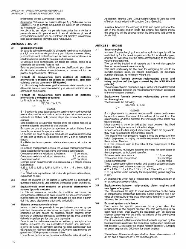
3.3 Fórmula de equivalencia entre motores de pistones alternativos y motores de turbinaLa fórmula es la siguiente:
S(3,10 x T) - 7,63C =
0,09625S = Sección de paso (expresada en centímetros cuadrados) del aire a alta presión, a la salida de los álabes del estator (o a la salida de los álabes de la primera etapa si el estator tiene varias etapas).Esta sección es la superficie medida entre los álabes fijos de la primera etapa de la turbina de alta presión.En caso de que el ángulo de apertura de estos álabes fuera variable, se tomará la apertura máxima.La sección de paso es igual al producto de la altura (expresada en cm) por la anchura (expresada en cm) y por el número de álabes.R = Relación de compresión relativa al compresor del motor de turbina.Se obtiene multiplicando entre sí los valores correspondientes a cada etapa del compresor, como se indica a continuación:Compresor axial de velocidad subsónica: 1,15 por etapa.Compresor axial de velocidad transónica: 1,5 por etapa.Compresor radial: 4,25 por etapa.Ejemplo de un compresor de una etapa radial y 6 etapas axiales subsónicas:4,25 x 1,15 x 1,15 x 1,15 x 1,15 x 1,15 x 1,15 o bien: 4,25 x (1,15)6.C = Cilindrada equivalente del motor de pistones alternativos, expresada en cm3.
3.4 Todos los motores en los cuales el carburante es inyectado o quemado después de una lumbrera de escape están prohibidos.
3.5 Equivalencias entre motores de pistones alternativos y nuevos tipos de motoresLa FIA se reserva el derecho de modificar las bases de comparación establecidas entre motores de tipo convencional y nuevos tipos de motores, con un preaviso de dos años a partir del 1 de enero siguiente a la toma de la decisión.
3.6 Sistema de escape y silenciosoIncluso cuando las prescripciones particulares para un grupo permitan reemplazar el silencioso de origen, los vehículos que participen en una prueba de carretera abierta deberán llevar siempre un silencioso de escape conforme con las leyes de tráfico del o de los países por los que pasa la prueba.Para todos los vehículos usados en rallyes, y excepto si los límites impuestos por las autoridades locales son inferiores, el nivel de ruido en carretera abierta no debe sobrepasar 103 dB(A) para un régimen del motor de 3500 rpm para motores de gasolina y 2500 rpm para motores diésel.Los orificios de los tubos de escape deberán estar situados a
Application: Touring Cars (Group A) and Group R Cars. No kind of ballast is authorised in Production Cars (GroupN).
In rallies, however, the carrying of tools and spare parts for the car in the cockpit and/or inside the engine bay and/or inside the boot only will be allowed under the conditions laid down in Article 253.
ARTICLE 3 - ENGINE3.1 Supercharging
In case of supercharging, the nominal cylinder-capacity will be multiplied by 1.7 for petrol engines and by 1,5 for diesel engine, and the car will pass into the class corresponding to the fictive volume thus obtained.The car will be treated in all respects as if its cylinder-capacity thus increased were its real capacity.This shall particularly be the case for assigning the car to its cylinder-capacity class, its interior dimensions, its minimum number of places, its minimum weight, etc.
3.2 Equivalence formula between reciprocating piston and rotary engines (of the type covered by the NSU Wankel patents)The equivalent cubic capacity is equal to the volume determined by the difference between the maximum and minimum capacities of the combustion chamber.
3.3 Equivalence formula between reciprocating piston and turbine enginesThe formula is the following:
S(3,10 x T) - 7,63C =
0,09625S = High pressure nozzle area - expressed in square centimetres by which is meant the area of the airflow at the exit from the stator blades (or at the exit from the first stage if the stator has several stages).Measurement is done by taking the area between the fixed blades of the high-pressure turbine first stage.In cases where the first stage turbine stator blades are adjustable, they must be opened to their greatest extent.The area of the high-pressure nozzle is thus the product of the height (expressed in cm) by the width (expressed in cm) and by the number of blades.R = The pressure ratio is the ratio of the compressor of the turbine engine.It is obtained by multiplying together the value for each stage of the compressor, as indicated hereafter:Subsonic axial compressor: 1.15 per stageTrans-sonic axial compressor: 1.5 per stageRadial compressor: 4.25 per stageThus a compressor with one radial and six axial subsonic stages will be designated to have a pressure ratio of:4.25 x 1.15 x 1.15 x 1.15 x 1.15 x 1.15 x 1.15 or 4.25 x (1.15)6.C = Equivalent cubic capacity for reciprocating piston engines in cm3.
3.4 All engines into which fuel is injected and burned downstream of an exhaust port are prohibited.
3.5 Equivalencies between reciprocating piston engines and new types of enginesThe FIA reserves the right to make modifications on the basis of comparisons established between classic engines and new types of engines, by giving a two-year notice from the 1st January following the decision taken.
3.6 Exhaust system and silencerEven when the specific provisions for a group allow the replacement of the original silencer, the cars competing in an open-road event shall always be equipped with an exhaust silencer complying with the traffic regulations of the country(ies) through which the event is run.For all cars used in Rallies and unless the limits imposed by the local authorities are lower, the noise level on the open road must not exceed 103 dB(A) for an engine rotation speed of 3500 rpm for petrol engines and 2500 rpm for diesel engines.
The orifices of the exhaust pipes shall be placed at a maximum of 45 cm and a minimum of 10 cm from the ground.
11
ANEXO «J» - PRESCRIPCIONES GENERALESAPPENDIX “J” - GENERAL PRESCRIPTIONS
una altura máxima de 45 cm y mínima de 10 cm con relación al suelo.La salida del tubo de escape debe estar situada dentro del perímetro del vehículo y a menos de 10 cm de este perímetro, y por detrás del plano vertical que pasa a través del centro de la batalla.Además se deberá prever una protección adecuada con el fin de evitar que los tubos calientes causen quemaduras.El sistema de escape no debe tener un carácter provisional. Los gases de escape solo podrán salir por el extremo del sistema.Las piezas del chasis no pueden utilizarse para la evacuación de los gases de escape.Convertidor catalítico:En caso de que estuvieran homologadas dos versiones de un modelo de vehículo (escape catalizado y otro escape), los vehículos deberán cumplir con una u otra versión, cualquier combinación de las dos versiones está prohibida.Todos los vehículos equipados con un kit (VK– WRC – S2000-Rallye) deben estar provistos de un catalizador homologado.Para todos los grupos, todos los vehículos deben estar equipados con un catalizador original u homologado si estos son obligatorios en el país donde se matriculen.El catalizador de escape de un vehículo se podrá retirar si no es obligatorio en el país organizador.No se permite ninguna modificación a un catalizador homologado.Se debe presentar a los Comisarios Técnicos de la prueba una copia original del documento de homologación.
3.7 Puesta en marcha a bordo del vehículoMotor de arranque con una fuente de energía a bordo del vehículo, eléctrica u otra, que pueda ser accionada por el piloto sentado al volante.
3.8 CilindrosPara los motores sin camisas, es posible reparar los cilindros añadiendo material, pero no piezas.
ARTÍCULO 4 - TRANSMISIÓNTodos los vehículos deben estar equipados con una caja de cambios que incluya obligatoriamente una relación de marcha atrás en estado de funcionamiento cuando el vehículo toma la salida de una prueba, y que pueda ser seleccionada por el piloto sentado al volante.
ARTÍCULO 5 - SUSPENSIÓNLos elementos de la suspensión construidos parcial o totalmente en materiales compuestos están prohibidos.
ARTÍCULO 6 - RUEDASLas ruedas construidas parcial o totalmente de materiales compuestos están prohibidas.Medición de la anchura de rueda:La rueda estará montada en el vehículo y apoyada en el suelo, el vehículo se encontrará en condiciones de carrera, el conductor a bordo, la medición de la anchura de la rueda se efectuará en cualquier punto de la circunferencia del neumático, excepto en la zona de contacto con el suelo.Cuando se montan neumáticos múltiples como parte de una rueda completa, esta debe respetar las dimensiones máximas previstas para el grupo en el que son utilizadas (ver Artículo 255-5.4).
ARTÍCULO 7 - CARROCERÍA / CHASIS / MONOCASCO7.1 Los vehículos con carrocería transformable deberán ser
conformes, en todos sus puntos, a las prescripciones que afecten a los vehículos con carrocería abierta. Además, los vehículos con techo rígido escamoteable deben circular exclusivamente con el techo cerrado y sujeto.
7.2 Dimensiones interiores mínimasSi una modificación autorizada por al Anexo J afecta a una dimensión citada en la ficha de homologación, esta dimensión no podrá considerarse como criterio de elección de dicho vehículo.
7.3 HabitáculoLa inversión del lado de conducción es posible, siempre que el vehículo original y el modificado sean mecánicamente equivalentes y que las piezas usadas sean proporcionadas por el fabricante para dicha conversión para la familia de vehículos correspondiente.En particular, el paso de la columna de la dirección a través del monocasco debe efectuarse únicamente por el orificio previsto a
The exit of the exhaust pipe must be situated within the perimeter of the car and less than 10 cm from this perimeter, and aft of the vertical plane passing through the centre of the wheelbase.Moreover, adequate protection must be provided in order to prevent heated pipes from causing burns.The exhaust system must not be provisional.
Exhaust gas may only exit at the end of the system.
Parts of the chassis must not be used to evacuate exhaust gasses.Catalytic exhausts:Should two possible versions of one car model be homologated (catalytic and other exhaust), the cars must comply with one or other version, any combination of the two versions being prohibited.All cars equipped with a kit (VK - WRC - S2000-Rally) must be fitted with a homologated catalytic exhaust.For all groups, all cars must be fitted with an original or homologated catalytic exhaust if this is obligatory in the country in which they are registered, unless the catalytic exhaust is not obligatory in the organising country, in which case it may be removed.No modifications to a homologated catalytic converter are allowed.An authentic copy of the homologation document must be presented to the Scrutineers for the event.
3.7 Starting on board the vehicleStarter with electric or other source of energy on board operable by the driver when seated in the seat.
3.8 CylindersFor non-sleeved engines, it will be possible to repair the cylinders by adding material, but not parts.
ARTICLE 4 - TRANSMISSIONAll cars must be fitted with a gearbox including a reverse gear which must be in working order when the car starts the event, and be able to be operated by the driver when he is normally seated.
ARTICLE 5 - SUSPENSIONSuspension parts made partially or entirely from composite materials are prohibited.
ARTICLE 6 - WHEELSWheels made partially or entirely from composite materials are prohibited.
Measuring wheel width: The width is to be measured with the wheel mounted on the car, on the ground, the vehicle in race condition, driver aboard, at any point along the circumference of the tyre, except in the area in contact with the ground.
When multiple tyres are fitted as part of a complete wheel, the latter must comply with the maximum dimensions for the Group in which these tyres are used (see Article 255-5.4).
ARTICLE 7 - BODYWORK / CHASSIS / BODYSHELL7.1 Convertible vehicles must comply in all respects with the
specifications applying to open cars. In addition, cars with a rigid retractable roof must be driven exclusively with the roof closed and locked up.
7.2 Minimum inside dimensionsIf a modification authorised by Appendix J affects a dimension stated on the homologation form this dimension may not be retained as an eligibility criterion for the car.
7.3 CockpitInversion of the driving side is possible, on condition that the original car and the modified car are mechanically equivalent and that the parts used are provided by the manufacturer for such a conversion for the family concerned.In particular, the steering column must pass through the bodyshell only via the hole made for that purpose by the manufacturer for the family concerned.
12
ANEXO «J» - PRESCRIPCIONES GENERALESAPPENDIX “J” - GENERAL PRESCRIPTIONS
estos efectos por el constructor para la familia correspondiente.Para los vehículos de tipo S1600, S2000 Rallye y WRC, la inversión de la posición de conducción se obtendrá mediante un sistema de dirección completo homologado como Variante Opción por el constructor.El orificio que permite el paso de la columna de dirección a través de la carrocería debe ser homologado mediante este sistema.No está permitido instalar nada en el habitáculo excepto: ruedas, herramientas, piezas de repuesto, equipamiento de seguridad, equipamiento de comunicaciones, lastre (si está autorizado), depósito del líquido lavacristales (solo en Vehículos de Turismo [Grupo A]).Todas las piezas de recambio y herramientas deberán estar fijadas detrás de los asientos del piloto y/o del copiloto o bien debajo de los asientos del piloto y/o del copiloto. El espacio y el asiento del pasajero de un vehículo abierto no deben cubrirse de ninguna forma.Los contenedores para los cascos y herramientas situados en el habitáculo deberán estar hechos de materiales no inflamables y no deberán, en caso de incendio, emitir gases tóxicos.El montaje de origen de los airbags podrá retirarse, sin modificar el aspecto del habitáculo.
7.4 Todos los paneles de la carrocería y del chasis/monocasco serán, en todo momento, del mismo material que en el vehículo de origen homologado, y deberán ser del mismo espesor de material que en dicho vehículo homologado.Está prohibido todo tratamiento químico.
7.5 Fijación y protección de farosSe autoriza a abrir orificios en el frontal de la carrocería para los soportes de los faros, siempre que se limiten a las fijaciones.En rallyes, se podrán montar sobre los faros protecciones flexibles no reflectantes; no deberán sobrepasar la parte delantera del vidrio del faro en más de 10 cm.
7.6 Todo objeto que suponga peligro (batería, productos inflamables, etc.) debe transportarse fuera del habitáculo.
7.7 Faldillas guardabarros (solamente en rallyes)Se pueden montar faldillas guardabarros transversales conforme al artículo siguiente:Si las faldillas guardabarros transversales son obligatorias, esta obligación debe ser mencionada en el reglamento particular de la prueba. Y, en todo caso, las faldillas guardabarros transversales son aceptadas con las siguientes condiciones:- Serán fabricados de material plástico flexible con un espesor
mínimo de 4 mm (densidad mínima = 0,85 g/cm3).- Deben estar fijados a la carrocería.- Deben cubrir, como mínimo, la anchura de cada rueda pero
al menos un tercio de la anchura del vehículo (ver Dibujo 252-6) debe quedar libre por detrás de las ruedas delanteras y traseras.
- Deberá haber una separación de, al menos, 20 cm entre la faldilla derecha y la faldilla izquierda, por delante de las ruedas traseras.
- La parte inferior de estas faldillas guardabarros no debe estar a más de 10 cm cuando el vehículo está parado sin personas a bordo.
- Por encima y sobre toda la altura del neumático, toda la anchura del neumático (visto desde la parte trasera) debe estar cubierta.
Si el reglamento particular de la prueba lo autoriza o impone. se pueden instalar faldillas guardabarros, hechas de material flexible, en la parte delantera del vehículo con el fin de evitar las salpicaduras hacia delante.
No deben sobrepasar la anchura de la carrocería, ni sobrepasar en más de 10 cm la longitud original del vehículo, y, al menos, un tercio de la anchura del vehículo debe quedar libre por delante de las ruedas delanteras.
ARTÍCULO 8 - SISTEMA ELÉCTRICO8.1 Alumbrado y señalización
Un faro antiniebla puede cambiarse por otra luz y viceversa, siempre que el montaje de origen permanezca igual.Si los retrovisores originales tienen luces intermitentes incorporadas y el artículo del Anexo J aplicable al vehículo permite la sustitución de los retrovisores, las luces intermitentes deben ser conservadas aunque no es obligatorio que estén
For Super 1600, Super 2000 and WRC cars, the inversion of the driving side will be obtained by a complete steering system homologated in option variant by the manufacturer.
The hole allowing the passage of the steering column through the bodyshell must be homologated with this system.Only the following accessories may be installed in the cockpit: spare wheels, tools, spare parts, safety equipment, communication equipment, ballast (if permitted), windscreen washer water container (Touring Cars (Group A) only).
All spare parts and tools must be fixed either behind the driver’s and/or co-driver’s seats or underneath the driver’s and/or co-driver’s seats. The passenger area and seat of an open car must in no way be covered.Containers for helmets and tools situated in the cockpit must be made of non-inflammable material and they must not, in case of fire, give off toxic vapours.The original fitting of the air bags may be removed, without modifying the appearance of the bodywork.
7.4 All bodywork and chassis/bodyshell panels of the vehicle must be at all times of the same material as those of the original homologated car and must be of the same material thickness as that of the original homologated car.All chemical treatments are forbidden.
7.5 Headlamp mounting and protectionThe boring of holes in the front bodywork for light brackets is authorised, limited solely to mountings.In rallies, non-reflecting protectors made from flexible material may be mounted on the headlamps ; they must not protrude forwards beyond the headlamp glass by more than 10 cm.
7.6 Any object of a dangerous nature (inflammable products, etc.) must be carried outside the cockpit.
7.7 Mudflaps(inRalliesonly)It is possible to fit transverse mud flaps in conformity with the article below.If transverse mud flaps are mandatory, this requirement must be mentioned in the supplementary regulations of the event.
In any case, transverse mud flaps are accepted under the following conditions:- They must be made of a flexible plastic material at least 4mm
thick (minimum density = 0.85g/cm3).- They must be fitted to the bodywork.- They must cover at least the width of each wheel, but at least
one third of the width of the car (see Drawing 252-6) must be free behind the front wheels and the rear wheels.
- There must be a gap of at least 20 cm between the right and left mud flaps in front of the rear wheels.
- The bottom of these mud flaps must be no more than 10 cm from the ground when the car is stopped, with nobody on board.
- Above and over the entire height of the tyre, the entire width of the tyre must be covered (seen from behind).
Mud flaps to prevent splashing towards the front, made from flexible material, may be installed at the front of the vehicle, if the supplementary regulations of the event authorise them or impose them.
They must not protrude beyond the overall width of the vehicle, or beyond the original overall length by more than 10 cm, and at least one third of the width of the car must be free in front of the front wheels.
ARTICLE 8 - ELECTRICAL SYSTEM8.1 Lighting and signalling
A fog light may be changed for another light, and vice versa, provided that the original mounting remains the same.
If the original rear view mirrors incorporate direction indicators and if the article of Appendix J applicable to the vehicle permits the replacement of the rear view mirrors, the direction indicators must be retained without necessarily being integrated in the rear
13
ANEXO «J» - PRESCRIPCIONES GENERALESAPPENDIX “J” - GENERAL PRESCRIPTIONS
incorporadas en los retrovisores.8.2 Alternador y motor de arranque
La instalación de alternadores y motores de arranque es libre.8.3 Claxon
Solo en rallyes, el nivel de ruido producido por el claxon debe ser superior o igual a 97 dB durante al menos 3 segundos, medido a 7 m por delante del vehículo.
ARTÍCULO 9 - CARBURANTE - COMBURENTE9.1 El combustible debe ser gasolina comercial procedente del
surtidor de una estación de servicio, sin otro aditivo que un lubricante de venta habitual. El combustible debe cumplir con las siguientes especificaciones:- 102,0 RON y 90,0 MON máximo, 95,0 RON y 85,0 MON
mínimo para carburante sin plomo.- 100,0 RON y 92,0 MON máximo, 97,0 RON y 86,0 MON
mínimo para carburante con plomo. Las mediciones se harán conforme a las normas ASTM D
2699-86 y D 2700-86.- Densidad: entre 720 y 785 kg/m³ a 15 ºC (medida conforme a
la norma ASTM D 4052).- Un máximo de 2,8% de oxígeno (o 3,7% si el contenido en
plomo es menor de 0,013 g/l) y 0,5% de nitrógeno en peso como porcentaje máximo, el resto del carburante estará constituido exclusivamente de hidrocarburos y no contendrá ningún aditivo que aumente la potencia.
La medición del contenido de nitrógeno se efectuará según la norma ASTM D 3228 y la medición del contenido de oxígeno por análisis elemental con una tolerancia del 0,2%.- Cantidad máxima de peróxidos y compuestos nitroxidados:
100 ppm (ASTM D 3703 o, en caso de imposibilidad, UOP 33-82).
- Cantidad máxima de plomo: 0,40 g/l o la norma del país de la prueba si es inferior (ASTM D 3341 o D 3237).
- Cantidad máxima de benceno: 5 % en volumen (ASTM D 3606).- Tensión de vapor Reid máxima: 900 hPa (ASTM D 323).- Cantidad total vaporizada a 70 ºC: de 10% a 47% (ASTM D 86).- Cantidad total vaporizada a 100 ºC: de 30 % a 70 % (ASTM D 86).- Cantidad total vaporizada a 180 ºC: 85% mínimo (ASTM D 86).- Fin de ebullición máxima: 225 ºC (ASTM D 86).- Máximo residuo de destilación: 2% en volumen (ASTM D 86).La aceptación o el rechazo del carburante se efectuará según la ASTM D 3244 con una certeza del 95%.Para los vehículos con catalizador, está prohibido el uso de combustible con plomo.Si el carburante disponible localmente para una prueba no es de una calidad suficiente para su utilización por los concursantes, la ADN del país organizador deberá solicitar a la FIA una derogación, para permitir la utilización de un carburante que no se corresponda con las características antes definidas.
9.2 DiéselPara motores diésel, el carburante debe ser gasoil que cumpla con las siguientes especificaciones:- Tasa de hidrocarburos, en % de peso: 90,0 mín.- Densidad (kg/m³): 860 máx.- Número de cetano (ASTM D 613): 55 máx.- Número de cetano calculado: 55 máx.
(ASTM D 976-80)- Contenido de azufre 50 mg/kg máx.
(pr-EN-ISO/DIS 14596) (de acuerdo con la directiva 98/70/CE)
9.3 ComburenteComo comburente, solo podrá mezclarse aire con el combustible.
9.4 Procedimiento de repostajeAcoplamiento estándar:- En el caso de un sistema centralizado proporcionado por el
circuito o de un sistema proporcionado por los concursantes, la tubería de llenado estará provista de un acoplamiento estanco que se adaptará al orificio estandarizado instalado en el vehículo (según el Dibujo 252-5, el diámetro interior D tendrá un máximo de 50 mm).
- Todos los vehículos deberán estar provistos de un orificio de llenado conforme a este esquema.Este acoplamiento estanco responderá al principio de «hombre muerto» y, por lo tanto, no deberá incorporar ningún
view mirrors.8.2 Alternators and Alternator-starters
The mountings of the alternators and alternator-starters are free.8.3 Horn
In rallies only, the noise level produced by the horn must be greater than or equal to 97 dB during at least 3 seconds, measured 7m in front of the vehicle.
ARTICLE 9 - FUEL - COMBUSTIVE9.1 The fuel must be commercial petrol which comes from a
service station pump, without any additive other than that of a lubricant on current sale. The fuel must comply with the following specifications:- 102.0 RON and 90.0 MON maximum, 95.0 RON and 85.0
MON minimum for unleaded fuel.- 100.0 RON and 92.0 MON maximum, 97.0 RON and 86.0
MON minimum for leaded fuel. The measurements will be made according to the standards
ASTM D 2699-86 and D 2700-86.- Density between 720 and 785 kg/m3 at 15°C (measured
according to ASTM D 4052).- A maximum of 2.8 % oxygen (or 3.7 % if the lead content
is less than 0.013 g/l) and 0.5 % nitrogen by weight, the remainder of the fuel consisting exclusively of hydrocarbons and not containing any power-boosting additives.
The measuring of the nitrogen content will be carried out according to the standard ASTM D 3228 and that of the oxygen content by elemental analysis with a tolerance of 0.2 %.- Maximum content of peroxides and nitrooxide compounds: 100
ppm (ASTM D 3703 or in the case of impossibility UOP 33-82).- Maximum lead content: 0.40 g/l or the standard of the country
of the event if it is lower (ASTM D 3341 or D 3237).- Maximum benzene content: 5 % in volume (ASTM D 3606).- Maximum Reid vapour pressure: 900 hPa (ASTM D 323).- Distillation at 70°C: 10 % to 47 % (ASTM D 86).- Distillation at 100°C: 30 % to 70 % (ASTM D 86).- Distillation at 180° C: 85% mínimo (ASTM D 86).- Maximum final boiling point: 225 ºC (ASTM D 86).- Maximum residue: 2 % volume (ASTM D 86).
The fuel being accepted or rejected according to the standard ASTM D 3244 with a confidence limit of 95 %.For vehicles with a catalytic converter, leaded petrol is forbidden.
If the fuel available locally for the event is not of a sufficient quality for use by competitors, the ASN of the organising country must ask the FIA for a waiver in order to enable the use of fuel not corresponding to the characteristics defined above.
9.2 DieselFor Diesel engines, the fuel must be gas oil corresponding to the following specifications:- Hydrocarbon level, % by weight 90,0 min.- Density, kg/m3 860 máx.- Cetane number (ASTM D 613) 55 máx.- Calculated cetane number 55 máx.
(ASTM D 976-80)- Sulphur content 50 mg/kg máx.
(pr-EN-ISO/DIS 14596), according to directive 98/70/CE
9.3 OxydantOnly air may be mixed with the fuel as an oxidant.
9.4 Refuelling procedureStandardised coupling:- In case of a centralised system provided by the circuit or a
system provided by the competitors, the refuelling hose shall be provided with a leak-proof coupling to fit the standardised filler mounted on the car (in accordance with Drawing 252-5; the interior diameter D must not exceed 50 mm).
- All cars must be provided with a fuel filler complying with this diagram.This leak-proof fitting must comply with the dead man principle and must not therefore incorporate any retaining device when
14
ANEXO «J» - PRESCRIPCIONES GENERALESAPPENDIX “J” - GENERAL PRESCRIPTIONS
dispositivo de retención en posición abierta (bolas, pestañas, etcétera).
- El(los) respiradero(s) deben estar equipados con válvulas de cierre y no retorno concebidas según el mismo principio que los orificios de repostaje estándar y de un diámetro idéntico.
Durante el repostaje los respiraderos deberán estar conectados, con el acoplamiento apropiado, al depósito principal de suministro o bien a un recipiente transparente portátil de una capacidad mínima de 20 litros provisto de un sistema de cierre estanco.Estos bidones de desgasificación deberán vaciarse al principio de cada repostaje.En los casos en los que los circuitos no pudieran proporcionar a los concursantes un sistema centralizado, estos tendrán que repostar según el procedimiento anterior.En ningún caso, el nivel de la reserva de combustible en el depósito podrá estar a más de 3 metros sobre el nivel de la pista cuando se efectúe el repostaje, durante toda la prueba.
Los bidones de desgasificación deben ser conformes a uno de los Dibujos 252-1 o 252-2.El depósito de reserva y todas las partes metálicas del sistema de repostaje desde el acoplamiento por encima del caudalímetro hasta el depósito y su soporte deben conectarse eléctricamente a tierra.Se aconseja aplicar lo siguiente:
1. Cada box estará equipado con dos tomas de tierra de tipo aviación.
2. El sistema de repostaje (torre, depósito, tubería, tobera, válvulas y depósito de ventilación inclusive) debería estar conectado a una de las anteriores tomas de tierra durante toda la prueba.
3. El vehículo debería estar conectado, al menos momentáneamente, a la otra toma de tierra tan pronto como se detenga en el box.
4. No se conectará la tubería de combustible (de llenado o de ventilación) hasta que las condiciones 2 y 3 se hayan cumplido.
5. Todo el personal del box encargado del carburante debería usar ropa protectora antiestática.El depósito de repostaje podrá ser uno de los siguientes:- Un recipiente de caucho, de tipo FT3 1999, FT3.5 o FT5,
construido por un fabricante aprobado, o- Un depósito que se corresponda con uno de los Dibujos 252-3
o 252-4.Aplicación: Para Vehículos de Turismo (Grupo A), consultar las prescripciones generales de los Campeonatos de la FIA.
9.5 Ventilación de depósitosSe permite montar un depósito con una ventilación que salga a través del techo.
9.6 Instalación de depósitos FT3 1999, FT3.5 o FT5El depósito FT3 1999, FT3.5 o FT5 puede situarse en la posición del depósito original o en el maletero.
Debe preverse un orificio para evacuar el combustible que pudiera derramarse en el compartimento del depósito.La posición y el tamaño del orificio de llenado, así como del tapón de cierre, pueden cambiarse a condición de que la nueva instalación no sobresalga de la carrocería y presente todas las garantías contra una fuga de combustible hacia los compartimentos interiores del vehículo.Si el orificio de llenado está situado dentro del vehículo, debe estar separado del habitáculo por una protección estanca.
ARTÍCULO 10 - FRENOSLos discos de freno de carbono están prohibidos.
ARTÍCULO 11 - ALMACENAMIENTO DE ENERGÍALa cantidad total de energía recuperada almacenada en el vehículo no debe exceder de 200 kJ; esta energía podrá ser reutilizada sin sobrepasar 10 kJ a razón de 1 kW máximo.
ARTÍCULO 12 - REFRIGERACIÓNCon la excepción de la refrigeración del piloto, está prohibido en todo momento de la prueba, el transporte de cualquier refrigerante sólido, líquido o gaseoso, tanto en el interior como exterior del vehículo.
in an open position (spring-loaded, bayonet, etc.).
- The air vent(s) must be equipped with non return and closing valves having the same closing system as that of the standard filler and having the same diameter.
During refuelling the outlets of the air-vents must be connected with the appropriate coupling either to the main supply-tank or to a transparent portable container with a minimum capacity of 20 litres provided with a closing system rendering it completely leak-proof.The venting catch tanks must be empty at the beginning of the refuelling operation.In the cases where the circuits are unable to provide the entrants with a centralised system, they will have to refuel according to the above procedure.The level of the reserve tank may in no case be more than 3 metres above the level of the track where the refuelling is effected. This applies to the whole duration of the event.
The overflow bottles must conform to one of the Drawings 252-1 or 252-2.The reserve tank and all metal parts of the refuelling system from the coupling over the flow meter up to the tank and its rack must be connected electrically to the earth.
The application of the following is recommended:1. Each pit should be equipped with two aircraft type grounding
connections.2. The refuelling system (including tower, tank, hose, nozzle,
valves and vent bottle) should be connected to one of the above grounding connections for the entire duration of the race.
3. The car should be connected, at least momentarily, to the other grounding connection as soon as it stops in the pit.
4. No fuel hose connection (fill or vent) unless and until conditions 2 and 3 have been fulfilled.
5. All fuel-handling pit crew members should wear non-static protective clothing.The refuelling tank may be one of the following:- models made of rubber, of the type FT3 1999, FT3.5 or FT5,
built by an approved manufacturer, or- tanks conforming to one of the Drawings 252-3 or 252-4.
Application: For Touring Cars (Group A), refer to the general prescriptions of the FIA Championships.
9.5 Tank ventilationIt is authorised to equip a tank with ventilation exiting through the car roof.
9.6 Installation of the FT3 1999, FT3.5 or FT5 tankThe FT3 1999, FT3.5 or FT5 tank may be placed either in the original location of the tank or in the luggage compartment.
There must be an orifice to evacuate any fuel which may have spread into the tank compartment.The position and the dimension of the filler hole as well as that of the cap may be changed as long as the new installation does not protrude beyond the bodywork and guarantees that no fuel shall leak into one of the interior compartments of the car.
If the filler hole is situated inside the car, it must be separated from the cockpit by a liquid-tight protection.
ARTICLE 10 - BRAKESCarbon brake discs are forbidden.
ARTICLE 11 - ENERGY STORAGEThe total quantity of recuperated energy stocked in the car must not exceed 200 kJ; this energy may be re-used without exceeding 10 kJ by means of 1kW maximum.
ARTICLE 12 - COOLINGExcept for the sole purpose of cooling the driver, the transporting and/or use of any solid, liquid or gas cooling agent, whether inside or outside the car, is prohibited at all times throughout the event.
15
ARTÍCULO 253EQUIPAMIENTO DE SEGURIDAD (GRUPOS N Y A) /
SAFETY EQUIPMENT (GROUPS N, A)
ARTÍCULO 1Los Comisarios Deportivos podrán excluir a un vehículo cuya construcción parezca presentar peligro.
ARTÍCULO 2Si un dispositivo fuera opcional, deberá estar montado conforme a los reglamentos.
ARTÍCULO 3 - CANALIZACIONES Y BOMBAS3.1 Protección
Las canalizaciones de combustible, aceite y frenos deben estar protegidas externamente contra cualquier riesgo de deterioro (piedras, corrosión, roturas mecánicas, etc.) e internamente contra todo riesgo de incendio y de deterioro.Aplicación:Opcional para Grupo N, si se conserva la instalación de origen.Obligatorio para todos los grupos si no se mantiene la instalación de serie o si las canalizaciones pasan por el interior del vehículo y han sido retirados los materiales que las protegen.En el caso de las canalizaciones de combustible, las partes metálicas que están aisladas de la carrocería por piezas o elementos no conductores deben conectarse eléctricamente a ella.
3.2 EspecificacioneseinstalaciónAplicación obligatoria si la instalación de serie no se conserva.Las canalizaciones de agua de refrigeración o de aceite de lubricación deben ser exteriores al habitáculo.Las instalaciones de las canalizaciones de carburante, de aceite de lubricación y las que contengan fluido hidráulico a presión deben ser construidas de acuerdo con las siguientes especificaciones:- si son flexibles, estas canalizaciones deben tener racores
roscados, engastados o autoobturantes y un trenzado exterior resistente a la abrasión y al fuego (que no mantenga la combustión);
- deberán soportar una presión mínima medida a una temperatura de trabajo mínima de:
- Canalizaciones de combustible (salvo las conexiones a los inyectores y el radiador de refrigeración en el circuito de retorno al depósito): 70 bar (1000 psi) 135℃ (121,11℃).
- Canalizaciones de aceite lubricante:70 bar (1000 psi) 232°C (450 °F).
- Canalizaciones que contengan fluido hidráulico bajo presión:280 bar (4000 psi) 232°C (450 °F).
Si la presión de funcionamiento del sistema hidráulico es superior a 140 bar (2000 psi), la presión que debe soportar deberá ser, al menos, el doble de la presión de funcionamiento.Las canalizaciones de combustible y de fluido hidráulico podrán pasar por el habitáculo pero sin presentar racores o conexiones, salvo en las paredes delantera y trasera de conformidad con los Dibujos 253-59 y 253-60, y excepto en el circuito de frenos y el circuito de líquido de embrague.
3.3 Corte automático de combustibleRecomendado para todos los grupos:Todas las canalizaciones de combustible que alimentan al motor deben estar equipadas con válvulas de corte automático situadas directamente en el depósito de combustible que cierren automáticamente todas las canalizaciones de combustible presurizadas si una de esas canalizaciones se rompe o tiene fugas.Obligatorio:Todas las bombas de combustible deben funcionar solamente cuando el motor está en marcha, excepto durante el proceso de arranque.
3.4 Ventilación del depósito de combustibleEl conducto de ventilación del depósito de combustible así como las válvulas descritas a continuación deben tener las mismas especificaciones que las canalizaciones de gasolina (Artículo 3.2) y deben estar equipados con un sistema que cumpla con las siguientes especificaciones:- válvula antivuelco activada por la gravedad,- válvula de ventilación de flotador,
ARTICLE 1A car, the construction of which is deemed to be dangerous, may be excluded by the Stewards of the meeting.
ARTICLE 2If a device is optional, it must be fitted in a way that complies with regulations.
ARTICLE 3 - LINES AND PUMPS3.1 Protección
Fuel, oil and brake lines must be protected externally against any risk of deterioration (stones, corrosion, mechanical breakage, etc.) and internally against all risks of fire and deterioration.
Application:Optional for Group N if the series production fitting is retained.Obligatory for all the Groups if the series production fitting is not retained or if the lines pass inside the vehicle and their protective covering has been removed.In the case of fuel lines, the metal parts which are isolated from the shell of the car by non-conducting parts must be connected to it electrically.
3.2 SpecificationsandinstallationObligatory application if the series fitting is not retained.Lines containing cooling water or lubricating oil must be outside the cockpit.The fittings of fuel lines, lubricating oil lines and of those containing hydraulic fluid under pressure must be manufactured according to the specifications below:
- when flexible, these lines must have threaded, crimped or self-sealing connectors and an outer braid resistant to abrasion and flame (will not sustain combustion) ;
- minimum burst pressure measured at a minimum operating temperature of:
- Fuel lines (except the connections to the injectors and the cooling radiator on the circuit retourning to the tank): 70 bar (1000 psi) 135℃ (121,11℃).
- Lubricating oil lines :70 bar (1000 psi) 232 °C (450 °F).
- Lines containing hydraulic fluid under pressure:280 bar (4000 psi) 232 °C (450 °F).
If the operating pressure of the hydraulic system is greater than 140 bar (2000 psi), the burst pressure must be at least double the operating pressure.Lines containing fuel or hydraulic fluid may pass through the cockpit, but without any connectors inside except on the front and rear bulkheads according to Drawings 253-59 and 253-60, and on the braking circuit and the clutch fluid circuit.
3.3 Automatic fuel cut-offRecommended for all groups:All fuel feed pipes going to the engine must be provided with automatic cut-off valves located directly on the fuel tank which automatically close all the fuel lines under pressure if one of these lines in the fuel system is fractured or leaks.
Compulsory:All the fuel pumps must only operate when the engine is running, except during the starting process.
3.4 Fuel cell ventilationThe ventilation line of the fuel cell as far as the valves described below must have the same specifications as those of the fuel lines (Article 3.2) and must be fitted with a system complying with the following conditions :
- Gravity activated roll-over valve- Float chamber ventilation valve
16
ANEXO «J» - SEGURIDAD APPENDIX “J” - SAFETY
- válvula de sobrepresión con una presión máxima de 200mbar, que funcione cuando la válvula de ventilación de flotador esté cerrada.
Si el diámetro interior del tubo de ventilación del depósito de combustible supera los 20 mm, debe montarse una válvula de no retorno homologada por la FIA y tal como está definida en el Artículo 253-14.5.
ARTÍCULO 4 - SEGURIDAD DE FRENADODoble circuito accionado por el mismo pedal: La acción del pedal debe ejercerse, normalmente, sobre todas las ruedas; en caso de fuga en cualquier punto de las canalizaciones del sistema de frenos o de cualquier fallo en el sistema de transmisión de los frenos, el pedal deberá controlar, al menos, dos ruedas.Aplicación: Si se mantiene el sistema de serie, no es necesaria ninguna modificación.
ARTÍCULO 5 - FIJACIONES SUPLEMENTARIASSe instalarán, como mínimo, dos fijaciones suplementarias para cada uno de los capós.Los mecanismos de cierre originales deberán dejarse inoperantes o desmontarse.Aplicación: Opcional para Grupo N, obligatorio para los otros grupos.Los objetos grandes transportados a bordo del vehículo (como la rueda de repuesto, la caja de herramientas, etc.) deben estar firmemente sujetos.
ARTÍCULO 6 - CINTURONES DE SEGURIDAD6.1 Arneses
Utilización de dos bandas para los hombros y una banda abdominal; puntos de anclaje a la carrocería: dos para la banda abdominal, dos para las bandas de los hombros.Estos arneses deben estar homologados por la FIA y cumplir con las normas FIA n.º 8854/98 o 8853/98 .Además, los arneses utilizados en pruebas de circuito deben estar equipados con un sistema de apertura por hebilla giratoria.Para rallyes, es obligatorio transportar a bordo de manera permanente dos cuchillas cortacinturones. Deben ser fácilmente accesibles para el piloto y el copiloto estando sentados con los arneses abrochados.Por el contrario, se recomienda que el sistema de apertura sea de pulsador para pruebas que incluyan recorridos en carretera abierta.Las ADN podrán homologar puntos de anclaje situados en la estructura de seguridad durante la homologación de dicha estructura, a condición de que esos puntos de anclaje se sometan a las pruebas correspondientes.
6.2 InstalaciónEstá prohibido anclar los arneses a los asientos o a sus soportes.Un arnés de seguridad puede instalarse sobre los puntos de anclaje del vehículo de serie.Las ubicaciones geométricas recomendadas para los puntos de anclaje se muestran en el Dibujo 253-61.Las bandas de los hombros deben estar dirigidas hacia atrás y hacia abajo y deben instalarse de modo que no formen un ángulo mayor de 45º con la horizontal, a partir del borde superior del respaldo, aunque se recomienda que este ángulo no supere los 10º.
Los ángulos máximos con relación al eje del asiento son de 20º divergentes o convergentes.Si es posible, deberá utilizarse el punto de anclaje originalmente previsto por el constructor sobre el montante C.Los puntos de anclaje que impliquen un ángulo más elevado respecto de la horizontal no deberán usarse.En este caso, las bandas de los hombros de los arneses de 4 puntos podrán instalarse en los puntos de anclaje de las bandas abdominales de los asientos traseros instalados de origen por el constructor del vehículo.Para un arnés de 4 puntos, las bandas de los hombros deben instalarse de forma que se crucen simétricamente con relación al eje del asiento delantero.Las bandas abdominales y pélvicas no deben pasar sobre los lados del asiento, sino a través del asiento, con el fin de envolver y sujetar la región pélvica sobre la mayor área posible.
Las bandas abdominales deben ajustarse estrechamente en la unión de la cresta pélvica y la parte superior del muslo. Bajo ningún concepto deben utilizarse sobre la zona abdominal.
- Blow-off valve with a maximum over pressure of 200 mbar, working when the float chamber ventilation valve is closed.
If the internal diameter of the fuel tank breather venting tube is greater than 20 mm, a non-return valve homologated by the FIA and as defined in Article 253-14.5 must be fitted.
ARTICLE 4 - BRAKING SAFETY SYSTEMDouble circuit operated by the same pedal: the pedal shall normally control all the wheels ; in case of a leakage at any point of the brake system pipes or of any kind of failure in the brake transmission system, the pedal shall still control at least two wheels.Application: If this system is fitted in series production, no modifications are necessary.
ARTICLE 5 - ADDITIONAL FASTENERSAt least two additional safety fasteners must be fitted for each of the bonnet and boot lids.The original locking mechanisms will be rendered inoperative or removed.Application: Optional for Group N, obligatory for the other Groups.
Large objects carried on board the vehicle (such as the spare wheel, tool-kit, etc.) must be firmly fixed.
ARTICLE 6 - SAFETY BELTS
6.1 BeltsWearing of two shoulder straps and one lap strap ; anchorage points on the shell: two for the lap strap, two for the shoulder straps.These belts must be homologated by the FIA and comply with FIA standard n°8853/98 or 8854/98.Furthermore, the belts used in circuit competitions must be equipped with turnbuckle release systems.For rallies, two belt cutters must be carried on board at all times. They must be easily accessible for the driver and co-driver when seated with their harnesses fastened.On the other hand, it is recommended that for competitions which include public road sections, the belts be equipped with push button release systems.The ASNs may homologate mounting points on the safety cage when this cage is being homologated, on condition that they are tested.
6.2 InstallationIt is prohibited for the seat belts to be anchored to the seats or their supports.A safety harness may be installed on the anchorage points of the series car.The recommended geometrical locations of the anchorage points are shown in Drawing 253-61.In the downwards direction, the shoulder straps must be directed towards the rear and must be installed in such a way that they do not make an angle of more than 45° to the horizontal from the upper rim of the backrest, although it is recommended that this angle should not exceed 10°.The maximum angles in relation to the centre-line of the seat are 20° divergent or convergent.If possible, the anchorage point originally mounted by the car manufacturer on the C-pillar should be used.Anchorage points creating a higher angle to the horizontal must not be used.In that case, the shoulder straps of 4-point safety harnesses may be installed on the rear seat lap strap anchorage points originally mounted by the car manufacturer.
For a 4-point harness, the shoulder straps must be installed crosswise symmetrically about the centre-line of the front seat.
The lap and crotch straps should pass not over the sides of the seat but through the seat, in order to wrap and hold the pelvic region over the greatest possible surface.
The lap straps must fit tightly in the bend between the pelvic crest and the upper thigh. Under no conditions must they be worn over the region of the abdomen.
17
ANEXO «J» - SEGURIDAD APPENDIX “J” - SAFETY
Se debe evitar que las bandas se dañen al rozarse por el uso contra aristas vivas.- Si la instalación en los puntos de anclaje de serie fuese
imposible para las bandas de los hombros y/o pélvicas, deberán instalarse nuevos puntos de anclaje en la carrocería o el chasis, lo más cerca posible del eje de las ruedas traseras para las bandas de los hombros.Las bandas de los hombros pueden fijarse también a la estructura de seguridad o a una barra de refuerzo por medio de un lazo, o bien fijarse a los anclajes superiores de los cinturones traseros, o apoyarse o fijarse en un refuerzo transversal soldado entre los tirantes longitudinales traseros de la estructura (ver Dibujo 253-66).
En este caso, el uso de un refuerzo transversal está sujeto a las siguientes condiciones:- El refuerzo transversal será un tubo de, al menos,
38 mm x 2,5mm o 40 mm x 2 mm de acero al carbono estirado en frío sin soldadura, con una resistencia mínima a la tracción de 350N/mm2.
- La altura de este refuerzo será tal que las bandas de los hombros, hacia atrás, estén dirigidas hacia abajo con un ángulo de entre 10º y 45º con respecto a la horizontal, desde el borde superior del respaldo, se recomienda un ángulo de 10º.
- Se autoriza a fijar las bandas por medio de un lazo o por tornillos, pero en este último caso debe soldarse una pieza por cada punto de anclaje (ver Dibujo 253-67 para las dimensiones). Estas piezas se situarán en la barra de refuerzo y las bandas estarán fijadas a ellas por medio de tornillos M12 8.8 o 7/16 UNF.
- Cada punto de anclaje deberá resistir una carga de 1470 daN, o de 720 daN para las bandas pélvicas.
En el caso de un punto de anclaje para dos bandas (prohibido para las bandas de los hombros), la carga considerada será igual a la suma de las dos cargas requeridas.- Para cada nuevo punto de fijación creado, se utilizará una
placa de refuerzo en acero con una superficie de, al menos, 40 cm² y un espesor mínimo de 3 mm.
- Principios de fijación al chasis/monocasco:1) Sistema de fijación general: ver Dibujo 253-62.2) Sistema de fijación para las bandas de los hombros: ver Dibujo 253-
63.3) Sistema de fijación para las bandas pélvicas: ver Dibujo 253-64.
6.3 UtilizaciónUn arnés debe usarse en su configuración de homologación sin ninguna modificación o eliminación de piezas, y de conformidad con las instrucciones del fabricante.La eficacia y duración de los cinturones de seguridad está directamente relacionada con la forma en la que se instalan, usan y mantienen.Los cinturones deben reemplazarse después de un accidente grave y si se encuentran cortados, deshilachados o debilitados debido a la acción de la luz del sol o de productos químicos.También deben cambiarse si las piezas de metal o las hebillas están deformadas, dobladas o corroídas.Todo arnés que no funcione correctamente debe sustituirse.
ARTÍCULO 7 - EXTINTORES - SISTEMAS DE EXTINCIÓNEl uso de los siguientes productos está prohibido: BCF, NAF.7.1 En rallyes:
Aplicación de los Artículos 7.2 y 7.3.En pruebas de circuito, slalom, carrera de montaña:Aplicación de los Artículos 7.2 o 7.3.
7.2 Sistemas instalados7.2.1) Todos los vehículos deben estar equipados con un sistema de
extinción que figure en la Lista Técnica n.° 16: «Sistemas de extinción homologados por la FIA».
7.2.2) Todas las botellas de los extintores deberán protegerse adecuadamente y estar situadas en el habitáculo. La botella del extintor también puede estar situada en el maletero, siempre que se encuentre a menos de 300 mm de los bordes exteriores de la carrocería en todas las direcciones horizontales.Esa botella debe estar fijada, como mínimo, mediante 2 bandas metálicas bloqueadas con tornillos, y el sistema de fijación debe ser capaz de resistir una desaceleración de 25 g.Todo el equipo de extinción debe ser resistente al fuego. Las canalizaciones de plástico están prohibidas y las
Care must be taken that the straps cannot be damaged through chafing against sharp edges.- If installation on the series anchorage points is impossible for
the shoulder and/or crotch straps, new anchorage points must be installed on the shell or the chassis, as near as possible to the centre-line of the rear wheels for the shoulder straps.
The shoulder straps may also be fixed to the safety cage or to a reinforcement bar by means of a loop, and may also be fixed to the top anchorage points of the rear belts, or be fixed or leaning on a transverse reinforcement welded between the backstays of the cage (see Drawing 253-66).
In this case, the use of a transverse reinforcement is subject to the following conditions:- The transverse reinforcement shall be a tube measuring at
least 38mm x 2.5 mm or 40 mm x 2 mm, made from cold drawn seamless carbon steel, with a minimum tensile strength of 350 N/mm2.
- The height of this reinforcement must be such that the shoulder straps, towards the rear, are directed downward with an angle of between 10° and 45° to the horizontal from the rim of the backrest, an angle of 10° being recommended.
- The straps may be attached by looping or by screws, but in the latter case an insert must be welded for each mounting point (see Drawing 253-67 for the dimensions). These inserts will be positioned in the reinforcement tube and the straps will be attached to them using bolts of M12 8.8 or 7/16UNF specification.
- Each anchorage point must be able to withstand a load of 1470 daN, or 720 daN for the crotch straps.
In the case of one anchorage point for two straps (prohibited for shoulder straps), the load considered will be equal to the sum of the required loads.- For each new anchorage point created, a steel reinforcement
plate with a surface area of at least 40 cm2 and a thickness of at least 3 mm must be used.
- Principles of mounting to the chassis / monocoque:1) General mounting system: see Drawing 253-62.2) Shoulder strap mounting: see Drawing 253-63.3) Crotch strap mounting: see Drawing 253-64.
6.3 UseA safety harness must be used in its homologation configuration without any modifications or removal of parts, and in conformity with the manufacturer’s instructions.The effectiveness and longevity of safety belts are directly related to the manner in which they are installed, used and maintained.
The belts must be replaced after every severe collision, and whenever the webbing is cut, frayed or weakened due to the actions of chemicals or sunlight.They must also be replaced if metal parts or buckles are bent, deformed or rusted.Any harness which does not function perfectly must be replaced.
ARTICLE 7 - EXTINGUISHERS – EXTINGUISHING SYSTEMSThe use of the following products is prohibited: BCF, NAF.7.1 In rallies:
Articles 7.2 and 7.3 apply.In circuit events, slaloms, hillclimbs :Article 7.2 or 7.3 applies.
7.2 Systems mounted7.2.1) All cars must be equipped with an extinguishing system from
Technical List n°16: "Extinguisher systems homologated by the FIA".
7.2.2) All extinguishers must be adequately protected and must be situated within the cockpit. The container may also be situated in the luggage compartment on condition that it is at least 300 mm from the outer edges of the bodywork in all horizontal directions.It must be secured by a minimum of 2 screw-locked metallic straps and the securing system must be able to withstand a deceleration of 25 g.All extinguishing equipment must withstand fire. Plastic pipes are prohibited and metal pipes are obligatory.
18
ANEXO «J» - SEGURIDAD APPENDIX “J” - SAFETY
canalizaciones de metal son obligatorias.7.2.3) El piloto debe ser capaz de accionar todos los extintores
manualmente cuando esté sentado normalmente con sus cinturones abrochados y el volante en su sitio.Además, el dispositivo de accionamiento externo debe combinarse con un cortacorriente. Debe estar identificado con una letra «E» de color rojo dentro de un círculo blanco con el borde rojo y un diámetro mínimo de 10 cm.Para vehículos WRC, el accionamiento de interruptor de un extintor exterior o interior debe traer consigo el corte de suministro eléctrico de la batería y el motor.
7.2.4) El sistema debe funcionar en todas las posiciones.7.2.5) Las toberas de extinción deben ser las adecuadas al agente
extintor e instalarse de tal manera que no apunten directamente a la cabeza de los ocupantes.
7.3 Extintores manuales7.3.1) Todos los vehículos deben estar equipados con uno o dos
extintores.7.3.2) Agentes extintores permitidos: AFFF, FX G-TEC, Viro 3, polvo o
cualquier otro agente extintor homologado por la FIA.7.3.3) Cantidad mínima de agente extintor:
AFFF: 2,4 litrosFX G-TEC: 2,0 kgViro 3: 2,0 kgZero 360: 2,0 kgPolvo: 2,0 kg
7.3.4) Todos los extintores deben estar presurizados como se indica a continuación en función de su contenido:AFFF: de acuerdo con las instrucciones del fabricante.FX G-TEC y Viro 3: de acuerdo con las instrucciones del fabricante.Zero 360: de acuerdo con las instrucciones del fabricante.Polvo: 8 bar mínimo y 13,5 bar máximo.Además, en el caso de los AFFF, los extintores deberán estar equipados con un sistema que permita la verificación de la presión del contenido.
7.3.5) La información siguiente deberá figurar visiblemente en cada extintor:- capacidad;- tipo de agente extintor;- peso o volumen del agente extintor;- fecha en la que debe revisarse el extintor, que no debe ser
más de dos años después de la fecha de llenado o última revisión, o bien la fecha límite de validez correspondiente.
7.3.6) Todos los extintores deben estar protegidos adecuadamente. Sus fijaciones deben ser capaces de soportar una desaceleración de 25 g.Además, solo se aceptarán (dos como mínimo) las fijaciones metálicas de desprendimiento rápido con abrazaderas metálicas.
7.3.7) Los extintores deben ser fácilmente accesibles al piloto y copiloto.
ARTÍCULO 8 - ESTRUCTURAS DE SEGURIDAD8.1 Generalidades:
La instalación de una estructura de seguridad es obligatoria.Puede estar:
a) Fabricada de acuerdo con los requerimientos de los artículos siguientes.
b) Homologada o certificada por una ADN de acuerdo con los reglamentos de homologación para estructuras de seguridad.Se debe presentar a los Comisarios Técnicos de la prueba una copia original del documento de homologación o del certificado, aprobado por la ADN y firmado por técnicos cualificados que representen al fabricante.Toda nueva estructura de seguridad homologada o certificada por una ADN y vendida a partir del 01/01/2003, deberá estar identificada, de forma individual, mediante una placa de identificación colocada por el constructor, que no pueda copiarse ni retirarse (por ejemplo, soldada, troquelada o con un adhesivo autodestructible).La placa de identificación debe indicar el nombre del constructor, el número de homologación o de certificación de la ficha de homologación o del certificado de la ADN y el número de serie
7.2.3) The driver must be able to trigger all extinguishers manually when seated normally with his safety belts fastened and the steering wheel in place.Furthermore, a means of triggering from the outside must be combined with the circuit-breaker switch, or situated close to it. It must be marked with a letter "E" in red inside a white circle of at least 10 cm diameter with a red edge.For WRC type cars, the triggering of an external or internal extinguisher must compulsorily bring about engine and battery cut-off.
7.2.4) The system must work in all positions.7.2.5) Extinguisher nozzles must be suitable for the extinguishant and
be installed in such a way that they are not directly pointed at the occupants’ heads.
7.3 Manual extinguishers7.3.1) All cars must be fitted with one or two fire extinguishers.
7.3.2) Permitted extinguishants: AFFF, FX G-TEC, Viro3, powder or any other extinguishant homologated by the FIA.
7.3.3) Minimum quantity of extinguishant:AFFF: 2,4 litrosFX G-TEC: 2,0 kgViro 3: 2,0 kgZero 360: 2,0 kgPowder: 2,0 kg
7.3.4) All extinguishers must be pressurised according to the contents:AFFF: in accordance with the manufacturer’s instructionsFX G-TEC and Viro3: in accordance with the manufacturer’s instructionsZero 360: in accordance with the manufacturer’s instructionsPowder: 8 bar mínimo y 13,5 bar máximo.Furthermore, each extinguisher when filled with AFFF must be equipped with a means of checking the pressure of the contents.
7.3.5) The following information must be visible on each extinguisher:
- capacity- type of extinguishant- weight or volume of the extinguishant- date the extinguisher must be checked, which must be no
more than two years after either the date of filling or the date of the last check, or corresponding expiry date.
7.3.6) All extinguishers must be adequately protected. Their mountings must be able to withstand a deceleration of 25 g.
Furthermore, only quick-release metal fastenings (two minimum), with metal straps, will be accepted.
7.3.7) The extinguishers must be easily accessible for the driver and the co-driver.
ARTICLE 8 - SAFETY CAGES8.1 General:
The fitting of a safety cage is compulsory.It may be either :
a) Fabricated in compliance with the requirements of the following articles ;
b) Homologated or Certified by an ASN according to the homologation regulations for safety cages ;An authentic copy of the homologation document or certificate, approved by the ASN and signed by qualified technicians representing the manufacturer, must be presented to the event’s Scrutineers.Any new cage which is homologated by an ASN and is on sale, as from 01.01.2003, must be identified by means of an identification plate affixed to it by the manufacturer; this identification plate must be neither copied nor moved (i.e. embedded, engraved or self-destroying sticker).The identification plate must bear the name of the manufacturer, the homologation or certification number of the ASN homologation form or certificate and the individual series number of the manufacturer.
19
ANEXO «J» - SEGURIDAD APPENDIX “J” - SAFETY
único del fabricante.Un certificado en el que figuren los mismos números deberá llevarse a bordo y presentarse a los Comisarios Técnicos de la prueba.
c) Homologada por la FIA de acuerdo con el reglamento de homologación para estructuras de seguridad.Esta estructura de seguridad debe ser objeto de una extensión (VO) de la ficha de homologación del vehículo homologado por la FIA.La identificación del fabricante y un número de serie deben ser claramente visibles en todas las estructuras homologadas y vendidas desde el 1 de enero de 1997.La ficha de homologación de la estructura debe especificar cómo y dónde se indica esta información, y los compradores deben recibir el certificado numerado correspondiente.Para los siguientes vehículos, la estructura de seguridad debe estar homologada por FIA:Variante Kit Súper 1600, Variante Kit Súper 2000, Variante Kit Súper 2000 Rallye, Variante World Rallye Car.Toda modificación de una estructura de seguridad homologada o certificada está prohibida.Será considerado como modificación cualquier proceso sobre la estructura por medio de mecanizado o soldadura que implique una modificación permanente del material o de la estructura de seguridad.Cualquier reparación de una estructura de seguridad homologada o certificada que haya resultado dañada como consecuencia de un accidente debe ser realizada por el fabricante de la estructura o con su aprobación.Los tubos de las estructuras de seguridad no deben transportar fluidos ni ninguna otra cosa.Las estructuras de seguridad no deben dificultar la entrada o salida del piloto y del copiloto.Los elementos de la estructura pueden ocupar parte del espacio reservado para los ocupantes y atravesar el salpicadero, así como los revestimientos y los asientos traseros. Los asientos traseros pueden plegarse.
8.2 Definiciones:8.2.1 Estructura de seguridad:
Estructura multitubular instalada en el habitáculo muy cerca de la carrocería, concebida con el fin de evitar una deformación importante de la carrocería (chasis) en caso de accidente.
8.2.2 Arco de seguridad:Estructura tubular que forma un arco con dos bases de anclaje.
8.2.3 Arco principal (Dibujo 253-1):Estructura prácticamente vertical constituida por un arco tubular de una sola pieza (inclinación máxima +/-10° con respecto a la vertical) situado en un plano transversal al vehículo e inmediatamente detrás de los asientos delanteros.El eje del tubo debe estar contenido en un solo plano.
8.2.4 Arco delantero (Dibujo 253-1):Similar al arco principal pero su forma sigue los montantes del parabrisas y el borde superior del parabrisas.El eje del tubo debe estar contenido en un solo plano.
8.2.5 Arco lateral (Dibujo 253-2):Estructura casi longitudinal y prácticamente vertical constituida por un arco tubular de una sola pieza situado en la parte derecha o izquierda del vehículo; el pilar delantero de esta estructura sigue el montante del parabrisas y sus montantes traseros son casi verticales y están justo detrás de los asientos delanteros. Visto de lado, el montante trasero debe ser recto.
8.2.6 Semiarco lateral (Dibujo 253-3):Idéntico al arco lateral pero sin pilar trasero.
8.2.7 Tirante longitudinal:Tubo de una pieza casi longitudinal que une las partes superiores del arco principal y delantero.
8.2.8 Tirante transversal:Tubo semitransversal de una pieza que une los miembros superiores de los arcos o semiarcos laterales.
8.2.9 Tirante diagonal:Tubo transversal que une:uno de los ángulos superiores del arco principal, o uno de los extremos del miembro transversal en el caso de un arco lateral, y el pie de anclaje opuesto inferior del arcoo
A certificate bearing the same numbers must be carried on board and be presented to the event’s Scrutineers.
c) Homologated by the FIA according to the homologation regulations for safety cages.It must be the subject of an extension (VO) to the homologation form of the vehicle homologated by the FIA.The manufacturer’s identification and a series number must be clearly visible on all cages homologated and sold after 01.01.1997.The homologation form of the cage must specify how and where this information is indicated, and the purchasers must receive a numbered certificate corresponding to this.For the following cars, the cage must compulsorily be homologated by the FIA :Super 1600 Kit Variant, Super 2000 Kit Variant, Super 2000 Rally Kit Variant, World Rally Car Variant.Any modification to a homologated or certified safety cage is forbidden.To be considered as a modification, any process made to the cage by machining, weld, that involves a permanent modification of the material or the safety cage.All repairs to a homologated or certified safety cage, damaged after an accident must be carried out by the manufacturer of the rollcage or with his approval.Tubes of the safety cages must not carry fluids or any other item.
The safety cages must not unduly impede the entry or exit of the driver and co-driver.Members may intrude into the occupant’s space in passing through the dashboard and trim, as well as through the rear seats. The rear seat may be folded down.
8.2 Definitions:8.2.1 Safety cage :
Multi-tubular structure installed in the cockpit and fitted close to the bodyshell, the function of which is to reduce the deformation of the bodyshell (chassis) in case of an impact.
8.2.2 Rollbar :Tubular frame forming a hoop with two mounting feet.
8.2.3 Main rollbar (Drawing 253-1):Transverse and near-vertical (maximum angle +/-10° to the vertical) single piece tubular hoop located across the vehicle just behind the front seats.The tube axis must be within one single plane.
8.2.4 Front rollbar (Drawing 253-1):Similar to main rollbar but its shape follows the windscreen pillars and top screen edge.The tube axis must be within one single plane.
8.2.5 Lateral rollbar (Drawing 253-2):Near-longitudinal and near-vertical single piece tubular hoop located along the right or left side of the vehicle, the front pillar of which follows the windscreen pillar and the rear pillar of which is near-vertical and located just behind the front seats.
The rear pillar must be straight in side view.8.2.6 Lateral half-rollbar (Drawing 253-3):
Identical to the lateral rollbar but without the rear pillar.8.2.7 Longitudinal member :
Near-longitudinal single piece tube joining the upper parts of the front and main rollbars.
8.2.8 Transverse member:Near-transverse single piece tube joining the upper parts of the lateral half-rollbars or of the lateral rollbars.
8.2.9 Diagonal member :Transverse tube betweenOne of the top corners of the main rollbar, or one of the ends of the transverse member in the case of a lateral rollbar, and a the lower mounting point on the opposite side of the rollbar.
20
ANEXO «J» - SEGURIDAD APPENDIX “J” - SAFETY
el extremo superior de un tirante trasero con el punto de anclaje inferior del otro tirante trasero.
8.2.10 Tirantes desmontables:Miembros de una estructura de seguridad que deben poder desmontarse.
8.2.11 Refuerzo de la estructura:Miembro añadido a la estructura de seguridad para mejorar su resistencia.
8.2.12 Pie de anclaje:Placa soldada al final de un tubo de la estructura para permitir su atornillado y/o soldadura a la carrocería/chasis, generalmente sobre una placa de refuerzo.
8.2.13 Placa de refuerzo:Placa metálica fijada al monocasco/chasis bajo el pie de anclaje de un arco para repartir mejor la carga en el monocasco/chasis.
8.2.14 Cartela (Dibujo 253-34)Refuerzo para un ángulo o unión hecho de chapa doblada en forma de U de espesor no inferior a 1 mm.
Los extremos de la cartela (Punto E) deben estar situados a una distancia del punto superior del ángulo (Punto S) de 2 a 4 veces el diámetro exterior del tubo mayor de los tubos unidos.
8.3 Especificaciones8.3.1 Estructura básica
La estructura básica debe estar realizada de acuerdo con alguno de los diseños siguientes:* 1 arco principal + 1 arco delantero + 2 miembros longitudinales
+ 2 tirantes traseros + 6 pies de anclaje (Dibujo 253-1)o* 2 arcos laterales + 2 miembros transversales + 2 tirantes
traseros + 6 pies de anclaje (ver Dibujo 253-2)o* 1 arco principal + 2 semiarcos laterales + 1 miembro transversal
+ 2 tirantes traseros + 6 pies de anclaje (Dibujo 253-3).La parte vertical del arco principal debe ser tan recta como sea posible, estar lo más cerca posible del contorno interior de la carrocería y tener una sola curvatura en su parte vertical inferior.El montante delantero de un arco delantero o de un arco lateral debe seguir los montantes del parabrisas lo más cerca posible y tener una sola curvatura en su parte vertical inferior.Las conexiones de los miembros transversales de los arcos laterales, las conexiones de los miembros longitudinales al arco principal y delantero, así como la conexión de un semiarco lateral al arco principal, deben estar situadas al nivel del techo.En cualquier caso, no debe haber más de 4 uniones desmontables a nivel del techo.Los tirantes traseros deben anclarse cerca del techo y cerca de los ángulos superiores exteriores del arco principal, a ambos lados del vehículo, y está permitido hacerlo por medio de conexiones desmontables.Deberán formar un ángulo mínimo de 30° con la vertical y estar dirigidos hacia atrás, serán rectos y tan cercanos como sea posible a los paneles interiores laterales de la carrocería.
8.3.2 Diseño:Una vez que la estructura básica está definida, debe ser completada con miembros y refuerzos obligatorios (ver Artículo 253-8.3.2.1), a los cuales se podrán añadir miembros y refuerzos opcionales (ver Artículo 253-8.3.2.2).Salvo que esté explícitamente autorizado o que se utilicen conexiones desmontables de conformidad con el Artículo 253-8.3.2.4, todos los tirantes y refuerzos tubulares deben ser de una sola pieza.
8.3.2.1 Tirantes y refuerzos obligatorios:8.3.2.1.1 Tirante diagonal:
Vehículos homologados antes del 01/01/2002:La estructura debe incorporar uno de los tirantes diagonales definidos por los Dibujos 253-4, 253-5 y 253-6. La orientación de la diagonal puede invertirse. En el caso del Dibujo 253-6, la distancia entre los dos anclajes de la carrocería/chasis no debe ser superior a 300 mm.Los miembros deben ser rectos y pueden ser desmontables. El extremo superior de la diagonal debe unirse al arco principal a menos de 100 mm de la unión del arco principal con el tirante longitudinal trasero, o al tirante longitudinal trasero a menos de
orThe upper end of a backstay and the lower mounting point of the other backstay.
8.2.10 Removable members :Members of a safety cage which must be able to be removed.
8.2.11 Cage reinforcement :Member added to the safety cage to improve its strength.
8.2.12 Mounting foot :Plate welded to the end of a rollbar tube to permit its bolting and/or weld to the bodyshell/chassis, usually onto a reinforcement plate.
8.2.13 Reinforcement plate :Metal plate fixed to the bodyshell/chassis under a rollbar mounting foot to better spread the load onto the bodyshell/chassis.
8.2.14 Gusset (Drawing 253-34)Reinforcement for a bend or junction made from bent sheet metal with a U shape the thickness of which must not be less than 1.0 mm.The ends of this gusset (Point E) must be situated at a distance from the top of the angle (Point S) of between 2 to 4 times the outer diameter of the biggest of the tubes joined.
8.3 Specifications8.3.1 Basic structure
The basic structure must be made according to one of the following designs :* 1 main rollbar + 1 front rollbar + 2 longitudinal members + 2
backstays + 6 mounting feet (Drawing 253-1)
or* 2 lateral rollbars + 2 transverse members + 2 backstays + 6
mounting feet (Drawing 253-2)or* 1 main rollbar + 2 lateral half-rollbars + 1 transverse member +
2 backstays + 6 mounting feet (Drawing 253-3)
The vertical part of the main rollbar must be as close as possible to the interior contour of the bodyshell and must have only one bend with its lower vertical part.The front pillar of a front rollbar or of a lateral rollbar must follow the windscreen pillars as closely as possible and have only one bend with its lower vertical part.In order to build the safety cage, the connections of the transverse members to the lateral rollbars, the connections of the longitudinal members to the front and main rollbars, as well as the connection of a semi-lateral rollbar to the main rollbar must be situated at the roof level.In all cases, there must not be more than 4 removable connections at the roof level.The backstays must be attached near the roofline and near the top outer bends of the main rollbar, on both sides of the car, possibly by means of removable connections.They must form an angle of at least 30° with the vertical, must run rearwards and be straight and as close as possible to the interior side panels of the bodyshell.
8.3.2 Design:Once the basic structure is defined, it must be completed with compulsory members and reinforcements (see Article 253-8.3.2.1), to which optional members and reinforcements may be added (see Article 253-8.3.2.2).Unless explicitly permitted and unless dismountable joints are used in compliance with Article 253-8.3.2.4, all members and tubular reinforcements must be single pieces.
8.3.2.1 Compulsory members and reinforcements:8.3.2.1.1 Diagonal member :
Cars homologated before 01/01/2002:The cage must have one of the diagonal members defined by Drawings 253-4, 253-5, 253-6. The orientation of the diagonal may be reversed. In the case of Drawing 253-6, the distance between the two mountings on the bodyshell/chassis must not be greater than 300mm.Members must be straight and may be removable. The upper end of the diagonal must join the main rollbar no further than 100mm from its junction with the backstay, or the backstay no more than 100 mm from its junction with the main rollbar (see
21
ANEXO «J» - SEGURIDAD APPENDIX “J” - SAFETY
100 mm de su unión con el arco principal (ver Dibujo 253-52 para las medidas).El extremo inferior de la diagonal debe unirse al arco principal o a un tirante longitudinal trasero a menos de 100 mm del pie de anclaje (excepto para el caso del Dibujo 253-6).Vehículos homologados desde el 01/01/2002:La estructura debe tener dos miembros diagonales en el arco principal de acuerdo con el Dibujo 253-7.Los miembros deben ser rectos y pueden ser desmontables.El extremo inferior de la diagonal debe unirse con el arco principal o con el tirante trasero a menos de 100 mm del pie de anclaje (ver Dibujo 253-52 para las medidas).El extremo superior de la diagonal debe unirse al arco principal a menos de 100 mm de la unión de este con el tirante posterior.
8.3.2.1.2 Tirantes de puertas:Se deberán montar uno o varios tirantes longitudinales a cada lado del vehículo de acuerdo con los Dibujos 253-8, 253-9, 253-10 y 253-11 (Dibujos 253-9, 253-10 y 253-11 para vehículos homologados a partir de 01/01/2007). Los dibujos pueden combinarse entre sí.El diseño debe ser idéntico de ambos lados.Podrán ser desmontables.La protección lateral estará situada tan alta como sea posible, pero sus puntos de anclaje superiores no estarán a más de la mitad de la altura total de la abertura de la puerta medida desde su base.Si estos puntos de anclaje superiores están situados delante o detrás de la abertura de la puerta, esta limitación de altura es también válida para la intersección correspondiente al tirante y la abertura de la puerta.En el caso de una protección en «X» (Dibujo 253-9), es aconsejable que los puntos de anclaje inferiores de los tirantes se fijen directamente sobre el larguero longitudinal del monocasco (chasis) y que al menos una parte de la «X» sea una barra de una sola pieza.La conexión de los tirantes de puertas con el pilar de refuerzo del parabrisas (Dibujo 253-15) está autorizada.Para competiciones sin copiloto, dichos miembros pueden ser montados solo en el lado del conductor y no es obligatorio que el diseño sea idéntico en ambos lados.
8.3.2.1.3 Elementos de refuerzo de techo:Para vehículos homologados a partir del 01/01/2005 únicamente:La parte superior de la estructura de seguridad debe cumplir con las indicaciones de los Dibujos 253-12, 253-13 y 253-14.Los refuerzos pueden seguir la curvatura del techo.Para competiciones sin copiloto, en el caso del Dibujo 253-12 solamente, puede montarse un solo refuerzo pero su conexión delantera debe estar situada del lado del piloto.Los extremos de los refuerzos deben estar a menos de 100 mm de la unión entre arcos y miembros (esto no será de aplicación para la punta de la V formada por los refuerzos en los Dibujos 253-13 y 253-14).
8.3.2.1.4 Pilar de refuerzo del parabrisas:Para vehículos homologados a partir del 01/01/2006 únicamente:Deben estar montados a cada lado del arco delantero si la dimensión «A» es superior a 200 mm (ver Dibujo 253-15).Puede ser curvado a condición de que sea rectilíneo en vista lateral y que el ángulo de la curvatura no exceda los 20°.Su extremo superior debe estar a menos de 100 mm de la unión entre el arco delantero (lateral) y el miembro longitudinal (transversal) (ver Dibujo 253-52 para las medidas).Su extremo inferior debe estar a menos de 100 mm del pie de anclaje (delantero) del arco delantero (lateral).
8.3.2.1.5 Refuerzo de ángulos y uniones:Las uniones entre:- los miembros diagonales del arco principal,- los refuerzos del techo (configuración según Dibujo 253-12
y únicamente para vehículos homologados a partir de 01/01/2007),
- los tirantes de las puertas (configuración del Dibujo 253-9),- los tirantes de las puertas y los pilares de refuerzo del
parabrisas (Dibujo 253-15),deben estar reforzadas por un mínimo de 2 cartelas de conformidad con el Artículo 253-8.2.14.Si los tirantes de las puertas y el pilar de refuerzo del parabrisas no están situados en el mismo plano, el refuerzo puede estar
Drawing 253-52 for the measurement).
The lower end of the diagonal must join the main rollbar or the backstay no further than 100 mm from the mounting foot (except for the case of Drawing 253-6).Cars homologated as from 01/01/2002:The cage must have two diagonal members on the main rollbar according to Drawing 253-7.Members must be straight and may be removable.The lower end of the diagonal must join the main rollbar or the backstay no further than 100 mm from the mounting foot (see Drawing 253-52 for the measurement).The upper end of the diagonal must join the main rollbar no further than 100 mm from its junction with the backstay, or the backstay no more than 100 mm from its junction with the main rollbar.
8.3.2.1.2 Doorbars:One or more longitudinal members must be fitted at each side of the vehicle according to Drawings 253-8, 253-9, 253-10 and 253-11 (Drawings 253-9, 253-10 and 253-11 for cars homologated as from 01/01/2007). Drawings may be combined.The design must be identical on both sides.They may be removable.The side protection must be as high as possible, but its upper attachment point must not be higher than half the height of the door opening measured from its base.If these upper attachment points are located in front of or behind the door opening, this height limitation is also valid for the corresponding intersection of the strut and the door opening.
In the case of doorbars in the form of an “X” (Drawing 253-9), it is recommended that the lower attachment points of the cross-struts be fixed directly onto the longitudinal member of the bodyshell/chassis and that at least one part of the “X” be a single-piece bar.The connection of the doorbars to the windscreen pillar reinforcement (Drawing 253-15) is authorised.For competitions without co-driver, members may be fitted on the driver’s side only and it is not compulsory for the design to be identical on both sides.
8.3.2.1.3 Roof reinforcement:Cars homologated as from 01/01/2005 only:The upper part of the safety cage must comply with one of Drawings 253-12, 253-13 and 253-14.The reinforcements may follow the curve of the roof.For competitions without co-drivers, in the case of Drawing 253-12 only, only one diagonal member may be fitted but its front connection must be on the driver’s side.The ends of the reinforcements must be less than 100 mm from the junction between rollbars and members (not applicable to the top of the V formed by reinforcements in Drawings 253-13 and 253-14).
8.3.2.1.4 Windscreen pillar reinforcement:Cars homologated as from 01/01/2006 only:It must be fitted on each side of the front rollbar if dimension “A” is greater than 200 mm (Drawing 253-15).It may be bent on condition that it is straight in side view and that the angle of the bend does not exceed 20°.Its upper end must be less than 100 mm from the junction between the front (lateral) rollbar and the longitudinal (transverse) member (see Drawing 253-52 for the measurement).Its lower end must be less than 100 mm from the (front) mounting foot of front (lateral) rollbar.
8.3.2.1.5 Reinforcement of bends and junctions:The junctions between:- the diagonal members of the main rollbar,- the roof reinforcements (configuration of Drawing 253-12 and
only for cars homologated as from 01/01/2007),- the doorbars (configuration of Drawing 253-9),- the doorbars and the windscreen pillar reinforcement (Drawing
253-15),must be reinforced by a minimum of 2 gussets complying with Article 253-8.2.14.If the doorbars and the windscreen pillar reinforcement are not situated in the same plane, the reinforcement may be made of fabricated sheet metal, provided it complies with dimensions in
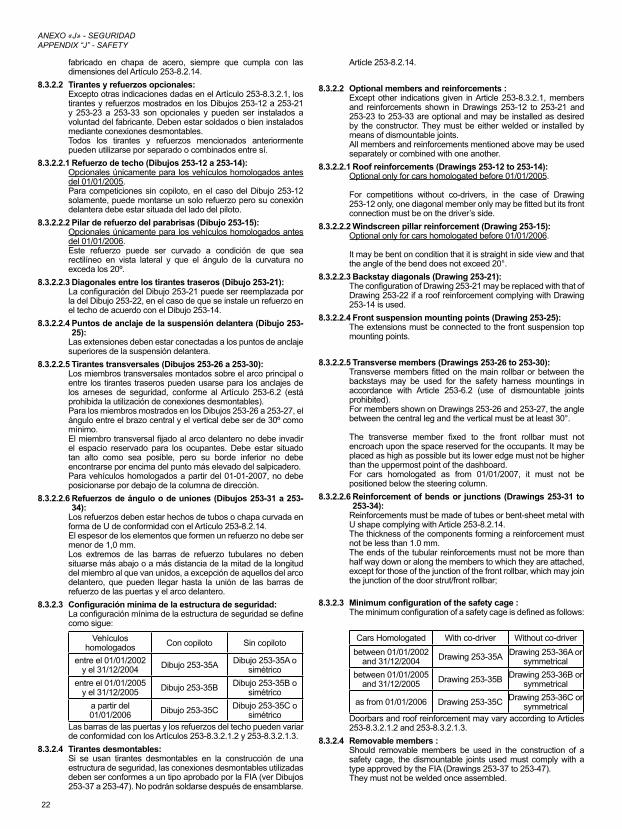
22
ANEXO «J» - SEGURIDAD APPENDIX “J” - SAFETY
fabricado en chapa de acero, siempre que cumpla con las dimensiones del Artículo 253-8.2.14.
8.3.2.2 Tirantes y refuerzos opcionales:Excepto otras indicaciones dadas en el Artículo 253-8.3.2.1, los tirantes y refuerzos mostrados en los Dibujos 253-12 a 253-21 y 253-23 a 253-33 son opcionales y pueden ser instalados a voluntad del fabricante. Deben estar soldados o bien instalados mediante conexiones desmontables.Todos los tirantes y refuerzos mencionados anteriormente pueden utilizarse por separado o combinados entre sí.
8.3.2.2.1 Refuerzo de techo (Dibujos 253-12 a 253-14):Opcionales únicamente para los vehículos homologados antes del 01/01/2005.Para competiciones sin copiloto, en el caso del Dibujo 253-12 solamente, puede montarse un solo refuerzo pero su conexión delantera debe estar situada del lado del piloto.
8.3.2.2.2 Pilar de refuerzo del parabrisas (Dibujo 253-15):Opcionales únicamente para los vehículos homologados antes del 01/01/2006.Este refuerzo puede ser curvado a condición de que sea rectilíneo en vista lateral y que el ángulo de la curvatura no exceda los 20º.
8.3.2.2.3 Diagonales entre los tirantes traseros (Dibujo 253-21):La configuración del Dibujo 253-21 puede ser reemplazada por la del Dibujo 253-22, en el caso de que se instale un refuerzo en el techo de acuerdo con el Dibujo 253-14.
8.3.2.2.4 Puntos de anclaje de la suspensión delantera (Dibujo 253-25):
Las extensiones deben estar conectadas a los puntos de anclaje superiores de la suspensión delantera.
8.3.2.2.5 Tirantes transversales (Dibujos 253-26 a 253-30):Los miembros transversales montados sobre el arco principal o entre los tirantes traseros pueden usarse para los anclajes de los arneses de seguridad, conforme al Artículo 253-6.2 (está prohibida la utilización de conexiones desmontables).Para los miembros mostrados en los Dibujos 253-26 a 253-27, el ángulo entre el brazo central y el vertical debe ser de 30º como mínimo.El miembro transversal fijado al arco delantero no debe invadir el espacio reservado para los ocupantes. Debe estar situado tan alto como sea posible, pero su borde inferior no debe encontrarse por encima del punto más elevado del salpicadero.Para vehículos homologados a partir del 01-01-2007, no debe posicionarse por debajo de la columna de dirección.
8.3.2.2.6 Refuerzos de ángulo o de uniones (Dibujos 253-31 a 253-34):
Los refuerzos deben estar hechos de tubos o chapa curvada en forma de U de conformidad con el Artículo 253-8.2.14.El espesor de los elementos que formen un refuerzo no debe ser menor de 1,0 mm.Los extremos de las barras de refuerzo tubulares no deben situarse más abajo o a más distancia de la mitad de la longitud del miembro al que van unidos, a excepción de aquellos del arco delantero, que pueden llegar hasta la unión de las barras de refuerzo de las puertas y el arco delantero.
8.3.2.3 Configuraciónmínimadelaestructuradeseguridad:La configuración mínima de la estructura de seguridad se define como sigue:
Vehículos homologados Con copiloto Sin copiloto
entre el 01/01/2002y el 31/12/2004 Dibujo 253-35A Dibujo 253-35A o
simétricoentre el 01/01/2005
y el 31/12/2005 Dibujo 253-35B Dibujo 253-35B o simétrico
a partir del 01/01/2006 Dibujo 253-35C Dibujo 253-35C o
simétricoLas barras de las puertas y los refuerzos del techo pueden variar de conformidad con los Artículos 253-8.3.2.1.2 y 253-8.3.2.1.3.
8.3.2.4 Tirantes desmontables:Si se usan tirantes desmontables en la construcción de una estructura de seguridad, las conexiones desmontables utilizadas deben ser conformes a un tipo aprobado por la FIA (ver Dibujos 253-37 a 253-47). No podrán soldarse después de ensamblarse.
Article 253-8.2.14.
8.3.2.2 Optional members and reinforcements :Except other indications given in Article 253-8.3.2.1, members and reinforcements shown in Drawings 253-12 to 253-21 and 253-23 to 253-33 are optional and may be installed as desired by the constructor. They must be either welded or installed by means of dismountable joints.All members and reinforcements mentioned above may be used separately or combined with one another.
8.3.2.2.1 Roof reinforcements (Drawings 253-12 to 253-14):Optional only for cars homologated before 01/01/2005.
For competitions without co-drivers, in the case of Drawing 253-12 only, one diagonal member only may be fitted but its front connection must be on the driver’s side.
8.3.2.2.2 Windscreen pillar reinforcement (Drawing 253-15):Optional only for cars homologated before 01/01/2006.
It may be bent on condition that it is straight in side view and that the angle of the bend does not exceed 20°.
8.3.2.2.3 Backstay diagonals (Drawing 253-21):The configuration of Drawing 253-21 may be replaced with that of Drawing 253-22 if a roof reinforcement complying with Drawing 253-14 is used.
8.3.2.2.4 Front suspension mounting points (Drawing 253-25):The extensions must be connected to the front suspension top mounting points.
8.3.2.2.5 Transverse members (Drawings 253-26 to 253-30):Transverse members fitted on the main rollbar or between the backstays may be used for the safety harness mountings in accordance with Article 253-6.2 (use of dismountable joints prohibited).For members shown on Drawings 253-26 and 253-27, the angle between the central leg and the vertical must be at least 30°.
The transverse member fixed to the front rollbar must not encroach upon the space reserved for the occupants. It may be placed as high as possible but its lower edge must not be higher than the uppermost point of the dashboard.For cars homologated as from 01/01/2007, it must not be positioned below the steering column.
8.3.2.2.6 Reinforcement of bends or junctions (Drawings 253-31 to 253-34):
Reinforcements must be made of tubes or bent-sheet metal with U shape complying with Article 253-8.2.14.The thickness of the components forming a reinforcement must not be less than 1.0 mm.The ends of the tubular reinforcements must not be more than half way down or along the members to which they are attached, except for those of the junction of the front rollbar, which may join the junction of the door strut/front rollbar;
8.3.2.3 Minimumconfigurationofthesafetycage:The minimum configuration of a safety cage is defined as follows:
Cars Homologated With co-driver Without co-driverbetween 01/01/2002
and 31/12/2004 Drawing 253-35A Drawing 253-36A or symmetrical
between 01/01/2005and 31/12/2005 Drawing 253-35B Drawing 253-36B or
symmetrical
as from 01/01/2006 Drawing 253-35C Drawing 253-36C or symmetrical
Doorbars and roof reinforcement may vary according to Articles 253-8.3.2.1.2 and 253-8.3.2.1.3.
8.3.2.4 Removable members :Should removable members be used in the construction of a safety cage, the dismountable joints used must comply with a type approved by the FIA (Drawings 253-37 to 253-47).They must not be welded once assembled.
23
ANEXO «J» - SEGURIDAD APPENDIX “J” - SAFETY
Los tornillos y las tuercas deben ser de calidad ISO 8.8 o superior (norma ISO).Las conexiones desmontables especificadas en los Dibujos 253-37, 253-40, 253-43, 253-46 y 253-47 están reservadas solamente para fijar los tirantes y los refuerzos opcionales descritos en el Artículo 253-8.3.2.2, y está prohibido utilizarlas para unir las partes superiores del arco principal, del arco delantero, de los semiarcos laterales y de los arcos laterales.
8.3.2.5 Especificacionescomplementarias:Longitudinalmente, la estructura de seguridad debe estar completamente contenida entre los anclajes de los elementos de las suspensiones delanteras y traseras que soportan las cargas verticales (muelles y amortiguadores).Los refuerzos suplementarios que excedan estos límites se autorizan entre la estructura de seguridad y los puntos de anclaje de las barras estabilizadoras traseras en el monocasco/chasis.Cada uno de esos puntos de anclaje puede ser conectado a la estructura de seguridad mediante un solo tubo de 30 x 1,5 mm.
Para vehículos homologados a partir del 01/01/2002:En protección frontal, los refuerzos de los ángulos y de las uniones de los ángulos superiores del arco delantero deben ser visibles únicamente a través de la superficie del parabrisas descrita en el Dibujo253-48.Para todas las estructuras de seguridad de los vehículos de «Súper 2000» homologados a partir del 01/01/2000 y para todas las estructuras de seguridad para vehículos de rallyes homologados a partir de 01/01/2001:La apariencia de la estructura de seguridad en la abertura de la puerta debe cumplir con los criterios siguientes (ver Dibujo 253-49):- Dimensión A: debe tener un mínimo de 300 mm.- Dimensión B: debe tener un máximo de 250 mm.- Dimensión C: debe tener un máximo de 300 mm.- Dimensión E: no debe ser superior a la mitad de la altura de la
abertura de la puerta (H).8.3.2.6 Puntos de anclaje de la estructura a la carrocería/chasis:
El mínimo de puntos de anclaje es:- uno para cada montante del arco delantero;- uno para cada montante de los arcos laterales o semiarcos
laterales;- uno para cada montante del arco principal;- uno para cada tirante longitudinal trasero.Para conseguir un montaje óptimo en la carrocería, el guarnecido original puede ser modificado junto a la estructura de seguridad o sus puntos de anclaje, recortándolo o modificándolo localmente.Sin embargo, esta modificación no permite la eliminación completa de partes de la tapicería o guarnecido.Si es necesario, la caja de fusibles podrá ser trasladada para permitir el montaje de la estructura de seguridad.Puntos de anclaje del arco delantero, arco principal, arcos laterales o semiarcos laterales:Cada punto de anclaje debe incluir una placa de refuerzo de un espesor de, al menos, 3 mm.Cada pie de anclaje debe estar fijado por, al menos, 3 tornillos en una placa de refuerzo de acero, soldada a la carrocería, que tenga al menos 3 mm de espesor y una superficie mínima de 120 cm2.Para vehículos homologados a partir del 01/01/2007, el área de 120 cm2 debe ser la superficie de contacto entre la placa de refuerzo y la carrocería. Se muestran ejemplos en los Dibujos 253-50 a 253-56.Para el Dibujo 253-52, la placa de refuerzo no requiere necesariamente estar soldada a la carrocería.En el caso del Dibujo 253-54, los laterales del punto de anclaje pueden cerrarse con una placa soldada.Los tornillos deben ser, al menos, de diámetro M8 y de calidad ISO 8.8 o superior (norma ISO). Las tuercas serán autoblocantes o dotadas de arandelas de bloqueo.El ángulo entre 2 tornillos (medido con respecto al eje central del tubo al nivel del pie de anclaje, cf. Dibujo 253-50) no debe ser inferior a 60grados.Puntos de anclaje de los tirantes traseros:Cada tirante longitudinal trasero deberá estar fijado con al menos 2 tornillos M8 y placas de refuerzo cuya superficie mínima sea de 60 cm2 (Dibujo 253-57), o bien fijado con un solo tornillo a doble cizalladura (Dibujo 253-58), siempre que este sea de la sección y resistencia adecuadas y a condición de que se suelde un manguito al tirante. Estas exigencias son las mínimas.
The screws and bolts must have a minimum quality of 8.8 (ISO standard).Dismountable joints complying with Drawings 253-37, 253-40, 253-43, 253-46 and 253-47 are solely for attaching optional members and reinforcements described by Article 253-8.3.2.2, and are forbidden for joining the upper parts of the main rollbar, of the front rollbar, of the lateral half-rollbars and of the lateral rollbars.
8.3.2.5 Additional constraints:Longitudinally, the safety cage must be entirely contained between the mounting points of the front and rear suspension elements carrying the vertical loads (springs and shock absorbers).Supplementary reinforcements exceeding these limits are authorised between the safety cage and the anchorage points of the rear anti-roll bars on the bodyshell/chassis.Each of these anchorage points may be connected to the safety cage by a single tube with dimensions of 30 x 1.5 mm.For cars homologated as from 01/01/2002:In frontal projection, reinforcements of bends and junctions of the upper corners of the front roll-cage must be only visible through the area of the windscreen described by Drawing 253-48.
For all the safety cages for “Super 2000” cars homologated as from 01/01/2000 and for all the safety cages for rally cars homologated as from 01/01/2001:
The presence of the cage reinforcements in the door aperture must comply with the following criteria (Drawing 253-49) :
- Dimension A must be a minimum of 300 mm- Dimension B must be a maximum of 250 mm- Dimension C must be a maximum of 300 mm- Dimension E must not be more than half the height of the door
aperture (H).8.3.2.6 Mounting of rollcages to the bodyshell/chassis :
Minimum mounting points are:- 1 for each pillar of the front rollbar;- 1 for each pillar of the lateral rollbars or lateral half-rollbars;- 1 for each pillar of the main rollbar;- 1 for each backstay.To achieve an efficient mounting to the bodyshell, the original interior trim may be modified around the safety cages and their mountings by cutting it away or by distorting it.However, this modification does not permit the removal of complete parts of upholstery or trim.Where necessary, the fuse box may be moved to enable a rollcage to be fitted.Mounting points of the front, main, lateral rollbars or lateral half-rollbars:Each mounting point must include a reinforcement plate at least 3 mm thick.Each mounting foot must be attached by at least three bolts on a steel reinforcement plate at least 3 mm thick and of at least 120cm2 area which is welded to the bodyshell.For cars homologated as from 01/01/2007, the area of 120 cm2 must be the contact surface between the reinforcement plate and the bodyshell. Examples according to Drawings 253-50 to 253-56.For Drawing 253-52, the reinforcement plate need not necessarily be welded to the bodyshell.In the case of Drawing 253-54, the sides of the mounting point may be closed with a welded plate.Fixing bolts must have a minimum diameter of M8 and a minimum quality of 8.8 (ISO standard). Fasteners must be self-locking or fitted with lock washers.The angle between 2 bolts (measured from the tube axis at the level of the mounting foot, cf. Drawing 253-50) must not be less than 60degrees.Mounting points of the backstays:Each backstay must be secured by a minimum of 2 M8 bolts (2008) with mounting feet of at least 60 cm2 area (Drawing 253-57), or secured by a single bolt in double shear (Drawing 253-58), provided it is of adequate section and strength and provided that a bush is welded into the backstay. These are minimum requirements.In addition, more fasteners may be used, the support plates of the mounting feet may be welded to reinforcement plates, the safety cage (as defined by Article 253-8.3.1) may be welded to
24
ANEXO «J» - SEGURIDAD APPENDIX “J” - SAFETY
Como complemento, pueden utilizarse fijaciones suplementarias, las placas de apoyo de los pies de los arcos pueden soldarse a las placas de refuerzo, la estructura de seguridad (tal como ha sido definida en el Artículo 253-8.3.1) puede soldarse a la carrocería/chasis.Caso especial:Para carrocerías/chasis que no sean de acero, cualquier soldadura entre la estructura de seguridad y la carrocería/chasis está prohibida, solo se permite el pegado de la placa de refuerzo en la carrocería/chasis.
8.3.3 EspecificacionesdelosmaterialesSolo se autorizan tubos de sección circular.Especificaciones de los tubos utilizados:
MaterialResistencia mínima a la
tracción
Dimensiones mínimas
(mm)Utilización
Acero al carbono no aleado (ver a continuación) conformado en frío conteniendo un máximo del
0,3% de carbono.
350 N/mm²
45 x 2,5(1,75" x 0,095")
o50 x 2,0
(2,0" x 0,083")
Arco principal (Dibujos 253-1 y 253-3) o arcos laterales y tirante trans-versal trasero (Dibujo
253-2)
38 x 2,5(1,5" x 0,095")
o40 x 2,0
(1,6" x 0,083")
Semiarcos laterales y otras partes de la
estructura de seguridad (salvo que se indique lo contrario en los Artículos
antes mencionados)
Nota: Para un acero no aleado, el contenido máximo de aditivos es de 1,7% para manganeso y de 0,6% para otros elementos.
Al seleccionar el acero, debe prestarse atención a la obtención de buenas propiedades de elongación y adecuadas características de soldabilidad.El curvado del tubo debe hacerse en frío con un radio de curvatura (medido en el eje del tubo) de, al menos, tres veces el diámetro del tubo.Si el tubo se ovaliza durante esta operación, la relación entre el diámetro menor y mayor deberá ser de 0,9 como mínimo.La superficie al nivel de los ángulos debe ser uniforme, sin ondulaciones ni fisuras.
8.3.4 Indicaciones para la soldadura:Deberá cubrir todo el perímetro del tubo. Todas las soldaduras deben ser de la mejor calidad posible y de una penetración total (preferentemente, soldadura al arco en atmósfera de gas inerte). Aunque una buena apariencia exterior no garantiza necesariamente la calidad de la soldadura, una soldadura de mala apariencia no será nunca señal de un buen trabajo.En el caso de utilizar acero tratado térmicamente, deben seguirse las instrucciones del fabricante (electrodos especiales, soldadura en atmósfera de gas inerte).
8.3.5 Revestimiento protector:En los lugares donde los cuerpos de los ocupantes puedan entrar en contacto con la estructura de seguridad, debe instalarse un revestimiento protector no inflamable.En aquellos puntos en los que los cascos de los ocupantes pudieran entrar en contacto con la estructura de seguridad, el revestimiento debe cumplir con la norma FIA 8857-2001 tipo A (ver la Lista Técnica n.° 23 «Revestimiento de arco de seguridad homologado por la FIA») y estar fijado de manera permanente a la estructura.Aplicación: Para todas las categorías.
ARTÍCULO 9 - VISIÓN HACIA ATRÁSLa visión hacia atrás debe estar asegurada por dos retrovisores exteriores (uno en el lado derecho y otro en el izquierdo). Estos retrovisores pueden ser los de serie.Cada retrovisor debe tener una superficie de cristal de espejo de al menos 90cm2.El retrovisor interior es opcional.Aplicación: Grupos N, A, R y Súper 2000 Rallyes. No obstante, un recorte en el cuerpo del retrovisor (superficie: máximo de 25 cm2 por retrovisor) se autoriza para ventilación del habitáculo.Aplicación: solo en rallyes, Grupos N, A, R y Súper 2000 Rallyes.
ARTÍCULO 10 - ANILLA PARA REMOLQUETodos los vehículos deben estar equipados con una anilla de remolque delantera y otra trasera en todas las pruebas. Este enganche solo se usará si el vehículo puede moverse libremente. Deberá ser fácilmente
the bodyshell/chassis.
Special case:For non steel bodyshells/chassis, any weld between the cage and the bodyshell/chassis is prohibited, only the bonding of the reinforcement plate on the bodyshell/chassis is permitted.
8.3.3 MaterialspecificationsOnly tubes with a circular section are authorised.Specifications of the tubes used:
Material Minimum tensile strength
Minimum Dimen-sions (mm) Use
Cold drawn sea-mless unalloyed carbon steel (see below) containing a maximum of 0,3
% of carbon
350 N/mm²
45 x 2,5(1,75" x 0,095")
or50 x 2,0
(2,0" x 0,083")
Main rollbar (Drawing 253-1 and 253-3) or
Lateral rollbar and rear transverse member
(Drawing 253-2)38 x 2,5
(1,5" x 0,095")or
40 x 2,0(1,6" x 0,083")
Lateral half-rollbars and others parts of the safety cage (unless otherwise indicated in the Articles
above)
Note: For an unalloyed steel, the maximum content of additives is 1.7 % for manganese and 0.6 % for other elements.In selecting the steel, attention must be paid to obtaining good elongation properties and adequate weldability.The tubing must be bent by a cold working process and the centreline bend radius must be at least 3 times the tube diameter.If the tubing is ovalised during bending, the ratio of minor to major diameter must be 0.9 or greater.The surface at the level of the bends must be smooth and even, without ripples or cracks.
8.3.4 Guidance on weld:These must be carried out along the whole perimeter of the tube. All weld must be of the highest possible quality with full penetration and preferably using a gas-shielded arc.Although good external appearance of a weld does not necessarily guarantee its quality, poor looking welds are never a sign of good workmanship.
When using heat-treated steel the special instructions of the manufacturers must be followed (special electrodes, gas protected weld).
8.3.5 Protective padding:Where the occupants’ bodies could come into contact with the safety cage, flame retardant padding must be provided for protection.Where the occupants’ crash helmets could come into contact with the safety cage, the padding must comply with FIA standard 8857-2001, type A (see Technical List n°23 "Roll Cage Padding Homologated by the FIA") and must be permanently fixed to the cage.Application: For all categories.
ARTICLE 9 - REAR VIEWRearward visibility must be ensured by two external rear-view mirrors (one on the right and one on the left). These rear-view mirrors may be as standard.Each rear-view mirror must have a reflecting surface of at least 90 cm2.
An inside rear-view mirror is optional.Application: Groups N, A, R and Super 2000 Rallies.A cut-out (maximum surface 25 cm² per mirror) is authorised in the rear view mirror housing for cockpit ventilation.Application: only in rallies, Groups N, A, R and Super 2000 Rallies.
ARTICLE 10 - TOWING-EYEAll cars will be equipped with a rear and front towing-eye for all events.This towing-eye will only be used if the car can move freely. It will be clearly visible and painted in yellow, red or orange.
25
ANEXO «J» - SEGURIDAD APPENDIX “J” - SAFETY
visible y estar pintada en amarillo, rojo o naranja.
ARTÍCULO 11 - LUNAS Y REDESLunas.Las lunas deben estar certificadas para su uso en carretera y su marcado debe dar fe de ello.En los vehículos de 4 o 5 puertas, puede montarse una pieza intermedia entre la parte superior de la ventanilla y la parte superior de la abertura de la ventanilla de la puerta trasera, siempre que dicha pieza no cumpla otra función más que la ventilación del habitáculo y que no sobresalga de la superficie exterior de la ventanilla.El parabrisas deberá ser de vidrio laminado.Puede contar con una o varias láminas transparentes (espesor total máximo: 400 micras) e incoloras en su cara exterior, salvo si esto se encuentra prohibido por la reglamentación vial del o de los países por los que pasa la prueba.Se autoriza una banda parasol, a condición de que permita a los ocupantes ver las señales de tráfico (semáforos, señales...).El uso de láminas tintadas y/o láminas de seguridad se autoriza en las ventanas laterales y en la luna trasera. En ese caso, deben permitir a una persona situada a 5m del vehículo ver al conductor así como el contenido del vehículo.
Solo en rallyes:Si no se utilizan láminas plateadas o tintadas o si las ventanillas laterales o el techo solar no están hechos de cristal laminado, es obligatorio el uso de láminas antidesintegración transparentes e incoloras en las ventanillas laterales y en el vidrio del techo solar.El espesor de dichas láminas no debe ser superior a 100 micras.El uso de láminas plateadas o tintadas se autoriza en las ventanas laterales, en la luna trasera y en el techo solar, bajo las siguientes condiciones:
- Diversas aberturas practicadas en estas láminas deben permitir a una persona situada en el exterior ver al conductor así como el contenido del vehículo.
- Esta autorización debe mencionarse en el reglamento particular de la prueba.
Aplicación: Grupos N, A y B.Redes.Para pruebas de circuito, el uso de redes fijadas a la estructura de seguridad es obligatorio. Estas redes deben tener las siguientes características:
- Anchura mínima de las bandas: 19 mm.- Tamaño mínimo de las aberturas: 25 x 25 mm.- Tamaño máximo de las aberturas: 60 x 60 mm.
Y deben recubrir la abertura de la ventanilla hasta el centro del volante.
ARTÍCULO 12 - FIJACIONES DE SEGURIDAD DEL PARABRISAS
Estas fijaciones pueden usarse libremente.Aplicación: Grupos N, A y B.
ARTÍCULO 13 - CORTACORRIENTEEl cortacorriente general debe cortar todos los circuitos eléctricos (batería, alternador o dinamo, luces, claxon, encendido, controles eléctricos, etc.), y debe parar el motor.Para motores diésel que no tengan inyectores controlados electrónicamente, el cortacorriente debe estar conectado a un dispositivo que interrumpa la admisión del motor.Debe ser un modelo antideflagrante y será accesible desde el interior y desde el exterior del vehículo.En el exterior, el sistema de accionamiento del cortacorriente estará situado, obligatoriamente, en la parte inferior de uno de los montantes del parabrisas en los vehículos cerrados. Estará claramente marcado por un rayo rojo en un triángulo azul con el borde blanco y una base de, al menos, 12 cm.Este accionamiento exterior solo afecta a vehículos cerrados.Aplicación: Instalación obligatoria para todos los vehículos que participen en pruebas de velocidad en circuito o montaña. Montaje recomendado para otras pruebas.
ARTÍCULO 14 - DEPÓSITOS DE SEGURIDAD APROBADOS POR LA FIA
En el caso de que un concursante utilice un depósito de combustible de seguridad, este deberá provenir de un fabricante aprobado por la FIA.Con el fin de obtener la aprobación de la FIA, un fabricante deberá haber probado la calidad constante de sus productos y su conformidad con las especificaciones aprobadas por la FIA.Los fabricantes de depósitos aprobados por la FIA se comprometen a
ARTICLE 11 - WINDOWS / NETSWindows.The windows must be certified for road use, their marking standing as proof. For cars with 4 or 5 doors, an intermediate part may be fitted between the upper part of the rear door window opening and the upper part of the rear door, provided that it has no function other than to ventilate the cockpit and that it does not protrude beyond the exterior surface of the window.
The winscreen must be made of laminated glass.It may be fitted with one or several transparent and colourless films (maximum total thickness of 400 microns) on its outer surface, unless this is forbidden by the traffic regulations of the country(ies) through which the event is run.A sun strip for the windscreen is authorised, on condition that it allows the occupants to see the road signs (traffic lights, traffic signs…).
The use of tinted glass and/or safety film is permitted in side and rear windows. In such cases it must be possible for a person situated 5 m from the car to see the driver as well as the contents of the car.
In rallies only:If silvered or tinted films are not used or if the side windows and the glass sunroof are not made from laminated glass, the use of transparent and colourless anti-shatter films on the side windows and the glass sunroof is mandatory.The thickness of these films must not be greater than 100microns.The use of silvered or tinted films is authorised, on the side and rear windows and on the glass sunroof, and on the following conditions:
- Openings in these films must allow a person outside the car to see the driver as well as the contents of the car.
- This authorisation must be mentioned in the supplementary regulations of the event.
Application: Groups N, A, B.Nets.For events on circuits, the use of nets affixed to the safety roll-cage is mandatory. These nets must have the following characteristics :
- Minimum width of the strips : 19 mm- Minimum size of the meshes : 25 x 25 mm.- Maximum size of the meshes : 60 x 60 mm.
and must close up the window opening to the centre of the steering wheel.
ARTICLE 12 - SAFETY FIXING DEVICES FOR WINDSCREENSuch devices may be used freely.Application: Groups N, A, B.
ARTICLE 13 - GENERAL CIRCUIT BREAKERThe general circuit breaker must cut all electrical circuits, battery, alternator or dynamo, lights, hooters, ignition, electrical controls, etc.) and must also stop the engine.For Diesel engines having no electronically controlled injectors, the circuit breaker must be coupled with a device cutting off the intake into the engine.It must be a spark-proof model, and will be accessible from inside and outside the car.As for the outside, the triggering system of the circuit breaker will compulsorily be situated at the lower part of the windscreen mountings for closed cars. It will be marked by a red spark in a white-edged blue triangle with a base of at least 12 cm.This outside triggering system only concerns closed cars.Application: Compulsory fitting for all cars taking part in speed events on circuits or hill-climbs. The fitting is recommended for other events.
ARTICLE 14 - FIA APPROVED SAFETY FUEL TANKSWhenever a competitor uses a safety fuel tank, it must come from a manufacturer approved by the FIA.In order to obtain the FIA’s agreement, a manufacturer must have proved the constant quality of its product and its compliance with the specifications approved by the FIA.Safety tank manufacturers recognised by the FIA must undertake to deliver to their customers exclusively tanks complying with the norms approved.To this end, on each tank delivered the name of the manufacturer, the exact specifications according to which this tank has been manufactured, the homologation date the date of the end of validity, and the series
26
ANEXO «J» - SEGURIDAD APPENDIX “J” - SAFETY
suministrar a sus clientes, exclusivamente, depósitos que cumplan con las normas aprobadas.Con este fin, sobre cada depósito suministrado deberá marcarse el nombre del fabricante, las especificaciones exactas según las cuales se ha fabricado ese depósito, el número de homologación, la fecha de caducidad y el número de serie.El proceso de marcaje debe ser indeleble y debe ser aprobado con antelación por la FIA de acuerdo a la norma existente.14.1 Especificacionestécnicas
La FIA se reserva el derecho de aprobar cualquier otro conjunto de especificaciones técnicas tras estudiar el expediente proporcionado por los fabricantes interesados.
14.2 EspecificacionesFT31999,FT3.5oFT5Las especificaciones técnicas para estos depósitos están disponibles, bajo petición, en la Secretaría de la FIA.
14.3 Envejecimiento de los depósitosEl envejecimiento de los depósitos flexibles implica una considerable reducción de sus propiedades físicas después de 5 años aproximadamente.No debe utilizarse ningún depósito más de 5 años después de su fecha de fabricación, excepto si es inspeccionado y revalidado por el fabricante durante un período de hasta otros dos años.Una tapa estanca, hecha de un material no inflamable, de fácil acceso y desmontable únicamente con herramientas, debe estar instalada en la protección de los depósitos de seguridad FT3 1999, FT3.5 o FT5 para permitir comprobar la fecha límite de validez.
14.4 Aplicacióndeestasespecificaciones.Los vehículos de Grupo N y de Grupo A podrán estar equipados con un depósito de seguridad FT3 1999, FT3.5 o FT5 si las modificaciones exigidas en el vehículo no sobrepasan aquellas permitidas por el reglamento.Se recomienda la utilización de espuma de seguridad en los depósitos FT3 1999, FT3.5 o FT5.
14.5 Depósitos de combustible con cuellos de llenado, Grupos A y NTodos los vehículos equipados con un depósito de combustible con un cuello de llenado que pase por el habitáculo, deben estar equipados con una válvula de no retorno homologada por la FIA. Esta válvula, del tipo «una o dos compuertas», debe instalarse en el cuello de llenado por el lado del depósito.El cuello de llenado se define como el elemento usado para conducir el combustible desde el orificio de llenado del vehículo hasta el interior del depósito.
ARTÍCULO 15 - PROTECCIÓN CONTRA INCENDIOSDebe colocarse una mampara de protección eficaz entre el motor y los asientos de los ocupantes, con el fin de evitar el paso directo de las llamas en caso de incendio.Si esta pantalla estuviera constituida por los asientos traseros, es recomendable recubrirlos con un material ignífugo.
ARTÍCULO 16 - ASIENTOS, PUNTOS DE ANCLAJE Y SOPORTES
Si se cambian las fijaciones o los soportes de origen, las nuevas piezas deben estar aprobadas por el fabricante del asiento para esa aplicación o bien cumplir con las especificaciones mencionadas a continuación.
1) Anclajes para fijación de soportes de asiento:Los soportes de los asientos deben estar fijados:
- sobre los anclajes de los asientos utilizados en el vehículos de origen;
- sobre los anclajes homologados por el constructor como Variante Opción (en este caso, los anclajes de origen podrán quitarse);
- Sobre los anclajes para la fijación de los asientos conforme al Dibujo253-54.
Los soportes de los asientos deben fijarse a los soportes de fijación de los asientos por medio de, al menos, 4 bulones por asiento y dichos bulones deben tener 8 mm de diámetro como mínimo.
2) Fijación de los soportes de asientos directamente a la carrocería/chasisLas fijaciones que se realicen en la carrocería/chasis deben estar compuestas, como mínimo, de 4 sujeciones por asiento y deben contar con tornillos de un diámetro mínimo de 8 mm y placas de refuerzo, de conformidad con el Dibujo 253-65.El área de contacto mínima entre el soporte, el chasis/carrocería y la contraplaca es 40 cm2 por cada fijación.
number, shall be marked.The marking process must be indelible and must have been approved beforehand by the FIA according to the prevailing standard.14.1 Technicalspecifications
The FIA reserves the right to approve any other set of technical specifications after study of the dossier submitted by the manufacturers concerned.
14.2 SpecificationsFT31999,FT3.5orFT5The technical specifications for these tanks are available, on request, from the FIA Secretariat.
14.3 Ageing of tanksThe ageing of safety tanks entails a considerable reduction in the strength characteristics after approximately five years. No bladder shall be used more than 5 years after the date of manufacture, unless inspected and recertified by the manufacturer for a period of up to another two years.
A leak-proof cover, made from non-flammable material, easily accessible and removable only with the use of tools, must be installed in the protection for FT3 1999, FT3.5 or FT5 tanks, in order to allow the checking of the validity expiry date.
14.4 ApplicationsofthesespecificationsGroup N and Group A cars may be equipped with an FT3 1999, FT3.5 or FT5 safety fuel tank if the modifications necessary do not exceed those allowed by the regulations.
The use of safety foam in FT3 1999, FT3.5 or FT5 tanks is recommended.
14.5 Fueltankswithfillernecks,GroupsAandNAll cars fitted with a fuel tank with filler neck passing through the cockpit must be equipped with a non-return valve homologated by the FIA. This valve, of the type "with one or two flaps", must be installed in the filler neck on the tank side."
The filler neck is defined as being the means used to connect the fuel filler hole of the vehicle to the fuel tank itself.
ARTICLE 15 - PROTECTION AGAINST FIREAn efficient protective screen must be placed between the engine and the occupant’s seat, in order to prevent the direct passage of flames in case of fire.Should this screen be formed by the rear seats, it is advisable to cover them with a flameproof coating.
ARTICLE 16 - SEATS, ANCHORAGE POINTS AND SUPPORTSIf the original seat attachments or supports are changed, the new parts must either be approved for that application by the seat manufacturer or must comply with the specifications mentioned below:
1) Anchorage points for fixing the seat supports:The seat supports must be fixed either:
- on the anchorage points for fixing seats used on the original car
- on the anchorage points for fixing seats homologated by the manufacturer as an Option Variant (in which case the original anchorage points may be removed)
- on anchorage points for fixing seats in conformity with Drawing253-54.
The seat supports must be fixed to the anchorage points for fixing seats via at least 4 mounting points per seat, using bolts measuring at least 8mm in diameter.
2) Fixing of the seat supports directly onto the shell/chassisSupports must be attached to the shell/chassis via at least 4 mounting points per seat using bolts with a minimum diameter of 8mm and counterplates, according to the Drawing 253-65.The minimum area of contact between support, shell/chassis and counterplate is 40 cm2 for each mounting point.
3) If quick release systems are used, they must capable of withstanding vertical and horizontal forces of 18000 N, applied non-simultaneously.If rails for adjusting the seat are used, they must be those originally supplied with the homologated car or with the seat.

27
ANEXO «J» - SEGURIDAD APPENDIX “J” - SAFETY
3) Si se utilizan sistemas de liberación rápida, estos deben ser capaces de resistir fuerzas verticales y horizontales de 18 000 N, no aplicadas de forma simultánea.Si se usan raíles para el reglaje del asiento, deben ser los suministrados originalmente con el vehículo homologado o con el asiento.
4) La fijación entre el asiento y los soportes debe estar compuesta de 4 sujeciones, 2 delanteras y 2 en la parte trasera del asiento, con tornillos de un diámetro mínimo de 8 mm y refuerzos integrados en el asiento.Cada sujeción deberá ser capaz de resistir una carga de 15 000 N aplicada en cualquier dirección.
5) El espesor mínimo de los soportes y de las contraplacas es de 3mm para el acero y 5 mm para materiales de aleación ligera.La dimensión longitudinal mínima de cada soporte es de 6cm.
6) Si hay un cojín entre el asiento homologado y el ocupante, su máximo espesor debe ser de 50mm.
Todos los asientos de los ocupantes deben ser homologados por la FIA (normas 8855/1999 o 8862/2009) y sin modificar.Para los asientos conformes a la norma FIA 8855/1999, el límite de uso es de 5 años a partir de la fecha de fabricación indicada en la etiqueta obligatoria.Una extensión de otros 2 años puede ser autorizada por el fabricante y debe ser indicada con una etiqueta adicional.Para los asientos conformes a la norma FIA 8862/2009, el límite de uso es de 10 años a partir del año de fabricación.Para los rallyes únicamente, los asientos correspondientes a la norma 8862/2009 podrán ser utilizados con soportes homologados por los constructores de automóviles como variante opción.
ARTÍCULO 17 - VÁLVULAS DE SOBREPRESIÓNEstán prohibidas las válvulas de sobrepresión en las ruedas.
MODIFICACIONES APLICABLES A PARTIR DEL 01/01/2013
8.2.14 Cartela (Dibujo 253-34)Refuerzo para un ángulo o unión hecho de chapa doblada en forma de U de espesor no inferior a 1 mm.
Los extremos de la cartela (Punto E) deben estar situados a una distancia del punto superior del ángulo (Punto S) de 2 a 4 veces el diámetro exterior del tubo mayor de los tubos unidos.Se autoriza un recorte en el punto más alto del ángulo, pero su radio (R) no debe ser superior a 1,5 veces el diámetro exterior del tubo mayor de los tubos unidos.Las caras planas de la cartela pueden tener un recorte cuyo diámetro no debe ser superior al diámetro exterior del tubo mayor de los tubos unidos.
4) The seat must be attached to the supports via 4 mounting points, 2 at the front and 2 at the rear of the seat, using bolts with a minimum diameter of 8 mm and reinforcements integrated into the seat.
Each mounting point must be capable of withstanding a force of 15000 N applied in any direction.
5) The minimum thickness of the supports and counterplates is 3 mm for steel and 5 mm for light alloy materials.The minimum longitudinal dimension of each support is 6 cm.
6) If there is a cushion between the homologated seat and the occupant, the maximum thickness of this cushion is 50mm.
All the occupants’ seats must be homologated by the FIA (8855/1999 or 8862/2009 standard) and not modified.For seats in compliance with 8855/1999 FIA standard, the limit for use is 5years from the date of manufacture indicated on the mandatory label.
An extension of 2 further years may be authorised by the manufacturer and must be indicated by an additional label.For seats in compliance with 8862/2009 FIA standard, the limit for use is 10 years from the year of manufacture.For Rallies only, seats corresponding to the standard 8862/2009 may be used with supports homologated by the car manufacturers in option variant.
ARTICLE 17 - PRESSURE CONTROL VALVESPressure control valves on the wheels are forbidden.
MODIFICATIONS APPLICABLES ON 01.01.2013
8.2.14 Gusset (Drawing 253-34)Reinforcement for a bend or junction made from bent sheet metal with a U shape the thickness of which must not be less than 1.0 mm.The ends of this gusset (Point E) must be situated at a distance from the top of the angle (Point S) of between 2 to 4 times the outer diameter of the biggest of the tubes joined.A cut-out is permitted at the top of the angle (R) but its radius must be no greater than 1.5 times the outer diameter of the biggest of the tubes joined.Theflatsidesofthegussetmayhaveaholethediameterof which must not be greater than the outer diameter of the biggest of the tubes joined.
28
ARTÍCULO 254REGLAMENTO ESPECÍFICO PARA VEHÍCULOS DE PRODUCCIÓN (GRUPO N) /
SPECIFIC REGULATIONS FOR PRODUCTION CARS (GROUP N)
ARTÍCULO 1 - DEFINICIÓNVehículos de turismo de gran producción en serie.
ARTÍCULO 2 - HOMOLOGACIÓNDe estos vehículos deberán haberse producido, al menos, 2500 unidades completamente idénticas en 12 meses consecutivos, y deberán ser homologadas por la FIA en Vehículos de Turismo (Grupo A).Las Variantes de Suministro (VF) de las fichas de Vehículos de Turismo (Grupo A) son igualmente válidas en los Vehículos de Producción (Grupo N). Todas las Variantes de Producción (VP) son válidas en Vehículos de Producción (Grupo N).Las Variantes Opción (VO) de la ficha de los Vehículos de Turismo (Grupo A) no serán válidas en los Vehículos de Producción (Grupo N), salvo que se refieran a:
- - volante motor del mismo diámetro y del mismo peso que el de origen, si y solamente si este volante de origen consta de dos partes;
- volante motor para cajas de cambios automáticas;- depósitos de combustible;- cajas de cambios automáticas;- techo solar (incluidos techos solares abatibles por encima de la línea
del techo);- estructura de seguridad;- soportes y anclajes de asientos;- puntos de fijación de los arneses.- versión 2/4 puertas.
Las Variantes Opción de Súper Producción (SP) no serán válidas en Vehículos de Producción (Grupo N).La utilización de depósitos homologados como VO en la ficha de Vehículos de Turismo (Grupo A) debe hacerse en las condiciones previstas por el Artículo 5.9.2 del reglamento de los Vehículos de Turismo (Grupo A) y el Artículo 254-6.8.Las Evoluciones de Tipo (ET) y las Variantes Kit (VK) homologadas en Grupo A no son válidas en los Vehículos de Producción (Grupo N).No obstante, las Evoluciones de Tipo homologadas a partir del 01/01/97 en Grupo A serán válidas en Grupo N.
ARTÍCULO 3 - NÚMERO DE PLAZASEstos vehículos deberán tener, al menos, cuatro plazas, según las dimensiones definidas para los Vehículos de Turismo (Grupo A).
ARTÍCULO 4 - MODIFICACIONES Y MONTAJES AUTORIZADOS U OBLIGATORIOS
Cualquier modificación que no se encuentre expresamente autorizada por el presente reglamento está prohibida.Los únicos trabajos que se podrán efectuar sobre el vehículo serán los necesarios para su mantenimiento normal, o la sustitución de piezas deterioradas por el uso o por accidente.Los límites de las modificaciones y montajes autorizados se especifican a continuación.Además de estas autorizaciones, toda pieza deteriorada por el uso o por accidente podrá reemplazarse únicamente por una pieza de origen idéntica a la pieza dañada.Los vehículos deberán ser estrictamente de serie e identificables por los datos que figuran en la ficha de homologación.
ARTÍCULO 5 - PESO MÍNIMO5.1 Los vehículos deberán tener, al menos, el peso que aparece en
su ficha de homologación.Es el peso real del vehículo vacío (sin personas o equipaje a bordo), sin herramientas ni gato y con un máximo de una rueda de repuesto.En el caso de llevar a bordo 2 ruedas de repuesto, la segunda rueda deberá ser retirada antes del pesaje.Todos los depósitos de líquidos (lubricación, refrigeración, frenado, calefacción, si ha lugar) deben estar al nivel normal previsto por el fabricante, excepto los depósitos del lavaparabrisas o lavafaros, del sistema de refrigeración de frenos, de combustible y de inyección de agua, que deberán estar vacíos.Los faros suplementarios que no figuren en la ficha de homologación deberán retirarse antes del pesaje.
5.2 En rallyes únicamente, el peso mínimo del vehículo (bajo las condiciones del Artículo 5,1) con el equipo a bordo (piloto +
ARTICLE 1 - DEFINITIONLarge scale series production touring cars.
ARTICLE 2 - HOMOLOGATIONAt least 2500 identical units must have been produced in 12 consecutive months and homologated by the FIA in Touring Cars (Group A).
The Supply Variants (VF) homologated in Touring Cars (Group A) are also valid in Production Cars (Group N). All Production Variants (VP) are valid in Production Cars (Group N).
Option Variants (VO) of the Touring Cars (Group A) form shall not be valid in Production Cars (Group N), unless they refer to:
- engine flywheel of the same diameter and the same weight as the original, if and only if this original flywheel is made up of two parts.
- fly-wheel for automatic gearboxes ;- fuel tank ;- automatic gearboxes ;- sun roof (includes the roof vents with a flap);- safety cage ;- seat supports and anchorages;- safety harness mounting points;- 2/4 doors versions.
Super Production Option Variants (SP) shall not be valid in Production Cars (Group N).The use of tanks homologated in VO on the Touring Car (Group A) form must be carried out under the conditions laid down in Article 5.9.2 of the Touring Car (Group A) regulations, and Article 254-6.8.
Evolutions of the type (ET), kit variants (VK) homologated in Touring Cars (Group A) are not valid in production Cars (Group N).Nevertheless, evolutions of the type homologated, as from 01.01.97 in Group A, are valid in Group N.
ARTICLE 3 - NUMBER OF SEATSCars must have at least four places, in accordance with the dimensions defined for Touring Cars (Group A).
ARTICLE 4 - MODIFICATIONS AND ADJUNCTIONS ALLOWED OR OBLIGATORY
All the modifications which are not allowed by the present regulations are expressly forbidden.The only work which may be carried out on the car is that necessary for its normal servicing, or for the replacements of parts worn through use or accident.The limits of the modifications and fittings allowed are specified hereinafter.Apart from these, any part worn through use or accident can only be replaced by an original part identical to the damaged one.
The cars must be strictly series production and identifiable from the information specified in the articles on the Homologation Form.
ARTICLE 5 - MINIMUM WEIGHT5.1 Cars must have at least the weight appearing on the homologation
form.This is the real weight of the empty car (without persons or luggage aboard) without tools or jack, and with a maximum of one spare wheel.When two spare wheels are carried in the car, the second spare wheel must be removed before weighing.All the liquid tanks (lubrication, cooling, braking, heating where applicable) must be at the normal level foreseen by the manufacturer, with the exception of the windscreen wiper or headlight wiper, brake cooling system, fuel and water injection tanks, which shall be empty.Additional headlights which do not appear on the homologation form must be removed before weighing.
5.2 In rallies only, the minimum weight of the car (under the conditions of Article 5.1) with crew (driver + co-driver + the full equipment of the driver and co-driver) will be: Minimum weight defined by
29
ANEXO «J» VEHÍCULOS DE PRODUCCIÓN DEL GRUPO NAPPENDIX “J” PRODUCTION CARS GROUP N
copiloto + equipamiento completo del piloto y del copiloto) será: Peso mínimo definido en el Artículo 5.1 + 150 kg. En cualquier caso, el peso definido por el Artículo 5.1 debe respetarse también.
ARTÍCULO 6 -6.1 Motor
- Los recubrimientos de plástico del motor que tengan la finalidad de cubrir los elementos mecánicos en el compartimento motor pueden retirarse si únicamente cumplen una función estética.
- Se permite retirar el material insonorizante y los guarnecidos montados bajo el capó motor y no visibles desde el exterior.
- Se permite reemplazar o duplicar el cable del mando del acelerador por otro que provenga, o no, del constructor. Este cable de repuesto debe ser un cable de emergencia, esto es, debe montarse en paralelo con el cable de acelerador de serie.Si el vehículo de serie está equipado con una mariposa motorizada, puede usarse un kit de acelerador de accionamiento mecánico homologado en Grupo N.
- Los tornillos y tuercas pueden cambiarse a condición de que continúen siendo de un material ferroso.
- Los sistemas de fijación de los manguitos del motor (refrigeración, intercambiador, admisión, aceite…) podrán ser reemplazados.
- Encendido: La marca y tipo de las bujías, del limitador de revoluciones y de los cables de alta tensión son libres.La caja y las piezas de la ECU relativas al encendido son libres. No obstante, el sistema deberá ser mecánicamente intercambiable con la unidad de origen.La instalación de origen debe ser conservada y no puede ser modificada.Si el cableado del motor atraviesa el paso de rueda, podrá ser desplazado.Los sensores y actuadores en el lado de entrada no pueden modificarse, ni tampoco su función.No se podrá añadir ningún sensor, incluso con la única finalidad de la obtención de datos. Se prohíbe añadir un interruptor en el cableado original entre la ECU y un sensor y/o actuador.En el caso en que un modelo esté equipado con un circuito eléctrico multiplexado, se permite el uso de cableado junto con una ECU homologada como Variante Opción.
- Todo sistema de adquisición de datos queda prohibido, salvo el que monte el vehículo homologado.Solo puede utilizarse el sistema de adquisición de datos que monte el vehículo de serie. En ningún caso, puede ser modificado o registrar parámetros adicionales.Se autoriza añadir solo los siguientes sensores: Temperatura de agua, temperatura de aceite, presión de aceite y régimen de motor.Cada uno de estos sensores podrá únicamente ser conectado a uno o varios registradores (con posibilidad de memorizar los datos) por medio de una instalación completamente independiente de cualquier otra instalación.
- Sistema de refrigeración: El termostato es libre, así como el sistema de control y la temperatura de encendido del ventilador. El sistema de bloqueo para el tapón del radiador es libre.
- Carburadores: Debe mantenerse el sistema original.Los elementos del carburador que controlan la cantidad de gasolina que entra en la cámara de combustión pueden modificarse, siempre que no tengan ninguna influencia sobre la admisión de aire.Se acepta la sustitución de los cartuchos del filtro de aire, siempre que sean como los de origen.
- Inyección: Debe mantenerse el sistema original.Los elementos del sistema de inyección situados después del dispositivo de medición del caudal de aire que regulan la cantidad de gasolina que entra en la cámara de combustión pueden modificarse, pero no suprimirse, siempre que no tengan ninguna influencia sobre la admisión de aire.La centralita electrónica para la inyección es libre.Las entradas de la ECU (sensores, actuadores, etc.), incluidas sus funciones, deben ser las de serie.Se prohíbe añadir un interruptor en el cableado original entre la ECU y un sensor y/o actuador.Las salidas de la ECU deben mantener sus funciones de origen según la ficha de homologación.
Article 5.1 + 150 kg. Furthermore, the weight defined in Article 5.1 must also be respected.
ARTICLE 6 -6.1 Engine
- Engine shields made of plastic material, the purpose of which is to hide mechanical components in the engine compartment, may be removed if they have a solely aesthetic function.
- Soundproofing material and trim fitted under the bonnet and not visible from the outside may be removed.
- The accelerator cable may be replaced or doubled by another one regardless of whether it comes from the manufacturer or not. This replacement cable must be an emergency cable, i.e. it must be fitted in parallel with the series accelerator cable.
If the series vehicle is fitted with a motorised throttle valve, a throttle kit with a mechanical linkage, homologated in Group N, may be used.
- The screws and bolts may be changed, provided that the replacements are made from ferrous material.
- The systems for attaching the engine pipes (cooling / exchanger / intake / oil…) may be replaced.
- Ignition: The make and type of the spark plugs, rev. limiter and high-tension leads are free.The electronic control unit and the ignition components in the electronic control unit are free, nevertheless the system must be mechanically interchangeable with the original unit.The original loom must be kept and cannot be modified.
If the engine loom passes via the wheel arch, it may be moved.
Sensors and actuators on the input side must be standard, as must their function.No sensor may be added, even for the purpose of data recording. It is prohibited to add a switch in the original wiring loom between the electronic control unit and a sensor and/or actuator.In the case of a model fitted with a multiplexed electric circuit, the use of a loom together with an electronic control unit homologated in Option Variant is permitted.
- Any data recording system is forbidden unless fitted on the homologated vehicle.Only the data logging system fitted to the series car may be used. In no case may it be modified or record additional parameters.Only the following sensors are authorised: Water temperature, oil temperature, oil pressure and engine speed.
Each of these sensors may only be linked to one or several visual display units (with data recording capability) by means of a harness that is completely independent of any other harness.
- Cooling system: The thermostat is free as is the control system and the temperature at which the fan cuts in. Locking system for the radiator cap is free.
- Carburettors: The original system must be retained.The components of the carburettor which control the quantity of petrol entering the combustion chamber may be modified, provided that they do not have any influence over the quantity of air admitted.Replacement air filter cartridges are accepted in the same way as the original ones.
- Injection: The original system must be retained.Components of the injection system situated downstream of the air-flow measuring device, and which control the quantity of petrol entering the combustion chamber may be modified but not replaced, provided that they do not have any influence over the quantity of air admitted.The electronic control unit for the injection is free.Inputs to the electronic control unit (sensors, actuators, etc.), including their function, must remain as standard.It is prohibited to add a switch in the original wiring loom between the electronic control unit and a sensor and/or actuator.Outputs from the electronic control unit must retain their original functions in accordance with the homologation form.
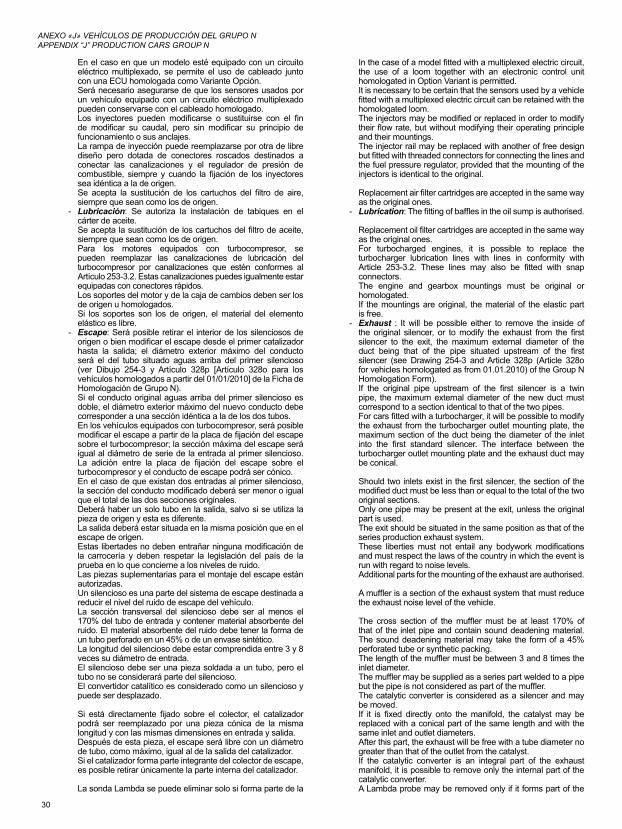
30
ANEXO «J» VEHÍCULOS DE PRODUCCIÓN DEL GRUPO NAPPENDIX “J” PRODUCTION CARS GROUP N
En el caso en que un modelo esté equipado con un circuito eléctrico multiplexado, se permite el uso de cableado junto con una ECU homologada como Variante Opción.Será necesario asegurarse de que los sensores usados por un vehículo equipado con un circuito eléctrico multiplexado pueden conservarse con el cableado homologado.Los inyectores pueden modificarse o sustituirse con el fin de modificar su caudal, pero sin modificar su principio de funcionamiento o sus anclajes.La rampa de inyección puede reemplazarse por otra de libre diseño pero dotada de conectores roscados destinados a conectar las canalizaciones y el regulador de presión de combustible, siempre y cuando la fijación de los inyectores sea idéntica a la de origen. Se acepta la sustitución de los cartuchos del filtro de aire, siempre que sean como los de origen.
- Lubricación: Se autoriza la instalación de tabiques en el cárter de aceite.Se acepta la sustitución de los cartuchos del filtro de aceite, siempre que sean como los de origen.Para los motores equipados con turbocompresor, se pueden reemplazar las canalizaciones de lubricación del turbocompresor por canalizaciones que estén conformes al Artículo 253-3.2. Estas canalizaciones puedes igualmente estar equipadas con conectores rápidos.Los soportes del motor y de la caja de cambios deben ser los de origen u homologados.Si los soportes son los de origen, el material del elemento elástico es libre.
- Escape: Será posible retirar el interior de los silenciosos de origen o bien modificar el escape desde el primer catalizador hasta la salida; el diámetro exterior máximo del conducto será el del tubo situado aguas arriba del primer silencioso (ver Dibujo 254-3 y Artículo 328p [Artículo 328o para los vehículos homologados a partir del 01/01/2010] de la Ficha de Homologación de Grupo N).Si el conducto original aguas arriba del primer silencioso es doble, el diámetro exterior máximo del nuevo conducto debe corresponder a una sección idéntica a la de los dos tubos.En los vehículos equipados con turbocompresor, será posible modificar el escape a partir de la placa de fijación del escape sobre el turbocompresor; la sección máxima del escape será igual al diámetro de serie de la entrada al primer silencioso. La adición entre la placa de fijación del escape sobre el turbocompresor y el conducto de escape podrá ser cónico.En el caso de que existan dos entradas al primer silencioso, la sección del conducto modificado deberá ser menor o igual que el total de las dos secciones originales.Deberá haber un solo tubo en la salida, salvo si se utiliza la pieza de origen y esta es diferente.La salida deberá estar situada en la misma posición que en el escape de origen.Estas libertades no deben entrañar ninguna modificación de la carrocería y deben respetar la legislación del país de la prueba en lo que concierne a los niveles de ruido.Las piezas suplementarias para el montaje del escape están autorizadas.Un silencioso es una parte del sistema de escape destinada a reducir el nivel del ruido de escape del vehículo.La sección transversal del silencioso debe ser al menos el 170% del tubo de entrada y contener material absorbente del ruido. El material absorbente del ruido debe tener la forma de un tubo perforado en un 45% o de un envase sintético.La longitud del silencioso debe estar comprendida entre 3 y 8 veces su diámetro de entrada.El silencioso debe ser una pieza soldada a un tubo, pero el tubo no se considerará parte del silencioso.El convertidor catalítico es considerado como un silencioso y puede ser desplazado.
Si está directamente fijado sobre el colector, el catalizador podrá ser reemplazado por una pieza cónica de la misma longitud y con las mismas dimensiones en entrada y salida.Después de esta pieza, el escape será libre con un diámetro de tubo, como máximo, igual al de la salida del catalizador.Si el catalizador forma parte integrante del colector de escape, es posible retirar únicamente la parte interna del catalizador.
La sonda Lambda se puede eliminar solo si forma parte de la
In the case of a model fitted with a multiplexed electric circuit, the use of a loom together with an electronic control unit homologated in Option Variant is permitted.It is necessary to be certain that the sensors used by a vehicle fitted with a multiplexed electric circuit can be retained with the homologated loom.The injectors may be modified or replaced in order to modify their flow rate, but without modifying their operating principle and their mountings.The injector rail may be replaced with another of free design but fitted with threaded connectors for connecting the lines and the fuel pressure regulator, provided that the mounting of the injectors is identical to the original.
Replacement air filter cartridges are accepted in the same way as the original ones.
- Lubrication: The fitting of baffles in the oil sump is authorised.
Replacement oil filter cartridges are accepted in the same way as the original ones.For turbocharged engines, it is possible to replace the turbocharger lubrication lines with lines in conformity with Article 253-3.2. These lines may also be fitted with snap connectors.The engine and gearbox mountings must be original or homologated.If the mountings are original, the material of the elastic part is free.
- Exhaust : It will be possible either to remove the inside of the original silencer, or to modify the exhaust from the first silencer to the exit, the maximum external diameter of the duct being that of the pipe situated upstream of the first silencer (see Drawing 254-3 and Article 328p (Article 328o for vehicles homologated as from 01.01.2010) of the Group N Homologation Form).If the original pipe upstream of the first silencer is a twin pipe, the maximum external diameter of the new duct must correspond to a section identical to that of the two pipes.For cars fitted with a turbocharger, it will be possible to modify the exhaust from the turbocharger outlet mounting plate, the maximum section of the duct being the diameter of the inlet into the first standard silencer. The interface between the turbocharger outlet mounting plate and the exhaust duct may be conical.
Should two inlets exist in the first silencer, the section of the modified duct must be less than or equal to the total of the two original sections.Only one pipe may be present at the exit, unless the original part is used.The exit should be situated in the same position as that of the series production exhaust system.These liberties must not entail any bodywork modifications and must respect the laws of the country in which the event is run with regard to noise levels.Additional parts for the mounting of the exhaust are authorised.
A muffler is a section of the exhaust system that must reduce the exhaust noise level of the vehicle.
The cross section of the muffler must be at least 170% of that of the inlet pipe and contain sound deadening material. The sound deadening material may take the form of a 45% perforated tube or synthetic packing.The length of the muffler must be between 3 and 8 times the inlet diameter.The muffler may be supplied as a series part welded to a pipe but the pipe is not considered as part of the muffler.The catalytic converter is considered as a silencer and may be moved.If it is fixed directly onto the manifold, the catalyst may be replaced with a conical part of the same length and with the same inlet and outlet diameters.After this part, the exhaust will be free with a tube diameter no greater than that of the outlet from the catalyst.If the catalytic converter is an integral part of the exhaust manifold, it is possible to remove only the internal part of the catalytic converter.A Lambda probe may be removed only if it forms part of the
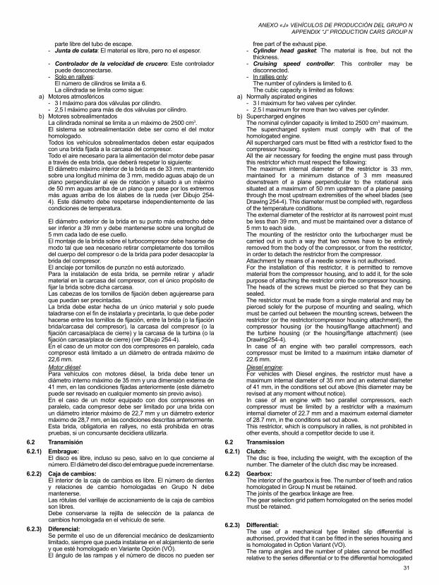
31
ANEXO «J» VEHÍCULOS DE PRODUCCIÓN DEL GRUPO NAPPENDIX “J” PRODUCTION CARS GROUP N
parte libre del tubo de escape.- Junta de culata: El material es libre, pero no el espesor.
- Controlador de la velocidad de crucero: Este controlador puede desconectarse.
- Solo en rallyes: El número de cilindros se limita a 6.La cilindrada se limita como sigue:
a) Motores atmosféricos- 3 l máximo para dos válvulas por cilindro.- 2,5 l máximo para más de dos válvulas por cilindro.
b) Motores sobrealimentadosLa cilindrada nominal se limita a un máximo de 2500 cm3.El sistema se sobrealimentación debe ser como el del motor homologado.Todos los vehículos sobrealimentados deben estar equipados con una brida fijada a la carcasa del compresor.Todo el aire necesario para la alimentación del motor debe pasar a través de esta brida, que deberá respetar lo siguiente:El diámetro máximo interior de la brida es de 33 mm, mantenido sobre una longitud mínima de 3 mm, medido aguas abajo de un plano perpendicular al eje de rotación y situado a un máximo de 50 mm aguas arriba de un plano que pase por los extremos más aguas arriba de los álabes de la rueda (ver Dibujo 254-4). Este diámetro debe respetarse independientemente de las condiciones de temperatura.
El diámetro exterior de la brida en su punto más estrecho debe ser inferior a 39 mm y debe mantenerse sobre una longitud de 5 mm cada lado de ese cuello.El montaje de la brida sobre el turbocompresor debe hacerse de modo tal que sea necesario retirar completamente dos tornillos del cuerpo del compresor o de la brida para poder desacoplar la brida del compresor.El anclaje por tornillos de punzón no está autorizado.Para la instalación de esta brida, se permite retirar y añadir material en la carcasa del compresor, con el único propósito de fijar la brida sobre dicha carcasa.Las cabezas de los tornillos de fijación deben agujerearse para que puedan ser precintadas.La brida debe estar hecha de un único material y solo puede taladrarse con el fin de instalarla y precintarla, lo que debe poder hacerse entre los tornillos de fijación, entre la brida (o la fijación brida/carcasa del compresor), la carcasa del compresor (o la fijación carcasa/placa de cierre) y la carcasa de la turbina (o la fijación carcasa/placa de cierre) (ver Dibujo 254-4).En el caso de un motor con dos compresores en paralelo, cada compresor está limitado a un diámetro de entrada máximo de 22,6 mm.Motor diésel:Para vehículos con motores diésel, la brida debe tener un diámetro interno máximo de 35 mm y una dimensión externa de 41 mm, en las condiciones fijadas anteriormente (este diámetro puede ser revisado en cualquier momento sin previo aviso).En el caso de un motor equipado con dos compresores en paralelo, cada compresor debe ser limitado por una brida con un diámetro interior máximo de 22,7 mm y un diámetro exterior máximo de 28,7 mm, en las condiciones descritas anteriormente.Esta brida, obligatoria en rallyes, no está prohibida en otras pruebas, si un concursante decidiera utilizarla.
6.2 Transmisión6.2.1) Embrague:
El disco es libre, incluso su peso, salvo en lo que concierne al número. El diámetro del disco del embrague puede incrementarse.
6.2.2) Caja de cambios:El interior de la caja de cambios es libre. El número de dientes y relaciones de cambio homologadas en Grupo N debe mantenerse.Las rótulas del varillaje de accionamiento de la caja de cambios son libres.Debe conservarse la rejilla de selección de la palanca de cambios homologada en el vehículo de serie.
6.2.3) Diferencial:Se permite el uso de un diferencial mecánico de deslizamiento limitado, siempre que pueda instalarse en el alojamiento de serie y que esté homologado en Variante Opción (VO).El ángulo de las rampas y el número de discos no pueden ser
free part of the exhaust pipe.- Cylinder head gasket: The material is free, but not the
thickness.- Cruising speed controller: This controller may be
disconnected.- In rallies only:
The number of cylinders is limited to 6.The cubic capacity is limited as follows:
a) Normally aspirated engines- 3 l maximum for two valves per cylinder.- 2.5 l maximum for more than two valves per cylinder.
b) Supercharged enginesThe nominal cylinder capacity is limited to 2500 cm3 maximum.The supercharged system must comply with that of the homologated engine.All supercharged cars must be fitted with a restrictor fixed to the compressor housing.All the air necessary for feeding the engine must pass through this restrictor which must respect the following:The maximum internal diameter of the restrictor is 33 mm, maintained for a minimum distance of 3 mm measured downstream of a plane perpendicular to the rotational axis situated at a maximum of 50 mm upstream of a plane passing through the most upstream extremities of the wheel blades (see Drawing 254-4). This diameter must be complied with, regardless of the temperature conditions.The external diameter of the restrictor at its narrowest point must be less than 39 mm, and must be maintained over a distance of 5 mm to each side.The mounting of the restrictor onto the turbocharger must be carried out in such a way that two screws have to be entirely removed from the body of the compressor, or from the restrictor, in order to detach the restrictor from the compressor.Attachment by means of a needle screw is not authorised.For the installation of this restrictor, it is permitted to remove material from the compressor housing, and to add it, for the sole purpose of attaching the restrictor onto the compressor housing.The heads of the screws must be pierced so that they can be sealed.The restrictor must be made from a single material and may be pierced solely for the purpose of mounting and sealing, which must be carried out between the mounting screws, between the restrictor (or the restrictor/compressor housing attachment), the compressor housing (or the housing/flange attachment) and the turbine housing (or the housing/flange attachment) (see Drawing254-4).In case of an engine with two parallel compressors, each compressor must be limited to a maximum intake diameter of 22.6 mm.Diesel engine:For vehicles with Diesel engines, the restrictor must have a maximum internal diameter of 35 mm and an external diameter of 41 mm, in the conditions set out above (this diameter may be revised at any moment without notice).In case of an engine with two parallel compressors, each compressor must be limited by a restrictor with a maximum internal diameter of 22.7 mm and a maximum external diameter of 28.7 mm, in the conditions set out above.This restrictor, which is compulsory in rallies, is not prohibited in other events, should a competitor decide to use it.
6.2 Transmission6.2.1) Clutch:
The disc is free, including the weight, with the exception of the number. The diameter of the clutch disc may be increased.
6.2.2) Gearbox:The interior of the gearbox is free. The number of teeth and ratios homologated in Group N must be retained.The joints of the gearbox linkage are free.The gear selection grid pattern homologated on the series model must be retained.
6.2.3) Differential:The use of a mechanical type limited slip differential is authorised, provided that it can be fitted in the series housing and is homologated in Option Variant (VO).The ramp angles and the number of plates cannot be modified relative to the series differential or to the differential homologated
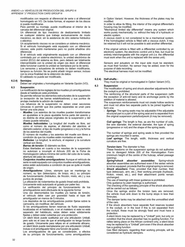
32
ANEXO «J» VEHÍCULOS DE PRODUCCIÓN DEL GRUPO NAPPENDIX “J” PRODUCTION CARS GROUP N
modificados con respecto al diferencial de serie o al diferencial homologado en VO. De todas formas, el espesor de los discos sí puede modificarse.Para permitir su montaje, puede modificarse el interior de la carcasa del diferencial original.Un diferencial de tipo mecánico de deslizamiento limitado es cualquier sistema que trabaja exclusivamente de modo mecánico, es decir, sin la asistencia de otro sistema hidráulico o eléctrico.Un acoplamiento viscoso no se considera un sistema mecánico. Si el vehículo homologado está equipado con un diferencial viscoso, este podrá mantenerse pero no podrá añadirse otro diferencial.Si el vehículo está originalmente equipado con un diferencial controlado por un sistema electrónico, la unidad electrónica de control (ECU) del sistema es libre, pero deberá ser totalmente intercambiable con la unidad de origen (es decir, el diferencial debe funcionar cuando la unidad se reemplace por la de serie).Los sensores y actuadores de entrada no deben modificarse, tampoco su función. No se podrá añadir ningún sensor, incluso con la única finalidad de la obtención de datos.El cableado no puede ser modificado.
6.2.4) Semiejes:Deben ser originales u homologados en Variante Opción (VO).
6.3 SuspensiónLa modificación de los reglajes de los muelles y/o amortiguadores desde el habitáculo está prohibida.Se permite reforzar los elementos estructurales de la suspensión (a excepción de las barras estabilizadoras) y sus puntos de anclaje mediante la adición de material.Los refuerzos de la suspensión no deben crear secciones cóncavas ni permitir que dos partes separadas se unan para formar una sola pieza.- Muelles: Los asientos de los muelles pueden transformarse
en ajustables si la pieza ajustable forma parte del asiento y es distinta de otras piezas originales de la suspensión y del chasis (puede retirarse).Muelles helicoidales: La longitud del muelle es libre, así como el número de espiras, el diámetro del alambre, el diámetro exterior, el tipo de muelle (progresivo o no) y la forma de los asientos del muelle.El número de muelles y los asientos del muelle son libres a condición de que los muelles estén montados en serie.Ballestas: La longitud, la anchura, el espesor y la curvatura vertical son libres.Barras de torsión: El diámetro es libre.Estas libertades en cuanto a los resortes de la suspensión no autorizan a incumplir el Artículo 205 de la Ficha de Homologación (altura mínima del centro del cubo de la rueda, abertura del paso de rueda).Conjuntos muelles-amortiguadores: Aunque el vehículo de serie no esté equipado con conjuntos muelles-amortiguadores, estos están autorizados a condición de que se quite el muelle de origen.
- Amortiguadores: Libres, siempre que se mantenga su número, su tipo (telescópico, de brazo, etc.), su principio de funcionamiento (hidráulico, de fricción, mixto, etc.) y sus puntos de anclaje.La utilización de rodamientos de guiado lineal está prohibida.Únicamente está autorizado el guiado por palier liso.La verificación del principio de funcionamiento de los amortiguadores será efectuada de la siguiente forma:Una vez desmontados los muelles y/o barras de torsión, el vehículo debe caer por gravedad hasta el tope del amortiguador en menos de 5 minutos.Los depósitos de los amortiguadores podrán fijarse sobre la carrocería, sin modificar, del vehículo.Si los amortiguadores tienen reservas de fluido separadas localizadas en el habitáculo, o en el maletero si este no está separado del habitáculo, estas deben estar sólidamente fijadas y deben estar cubiertas por una protección.Un silent block puede sustituirse por una articulación Uniball, pero solo en el caso de que el amortiguador no tenga función de guiado. Únicamente para rallyes en el continente africano, un silent block puede reemplazarse por una articulación Uniball, incluso si el amortiguador tiene una función de guiado.Los amortiguadores de gas se considerarán, a efectos de su principio de funcionamiento, como amortiguadores
in Option Variant. However, the thickness of the plates may be modified.In order to allow its fitting, the interior of the original differential’s housing may be modified."Mechanical limited slip differential" means any system which works purely mechanically, i.e. without the help of a hydraulic or electric system.A viscous clutch is not considered to be a mechanical system. If the homologated vehicle is fitted with a viscous clutch, it may be retained but it will not be possible to add another differential.
If the original vehicle is fitted with a differential controlled by an electronic system, the electronic control unit is free, but must be entirely interchangeable with the original unit (i.e. the differential must work when the unit is replaced with the series unit).
Sensors and actuators on the input side must be standard, as must their function. No sensor may be added, even for the purpose of data recording.The electrical harness must not be modified.
6.2.4) Half-shafts :They must be original or homologated in Option Variant (VO).
6.3 SuspensionThe modification of spring and shock absorber adjustments from the cockpit is prohibited.The reinforcing of the structural parts of the suspension (with the exception of anti-roll bars) and its anchorage points by the addition of material is allowed.The suspension reinforcements must not create hollow sections and must not allow two separate parts to be joined together to form one.- Springs: The spring seats may be adjustable if the adjustable
structural part is a part of the spring seat and is separated from the original suspension parts/bodywork (it may be removed).
Coil springs: The length is free, as are the number of coils, the wire diameter, the external diameter, the type of spring (progressive or not) and the shape of the spring seats.
The number of springs and spring seats is free provided the springs are mounted in series.Leaf springs: The length, width, thickness and vertical curvature are free.
Torsion bars: The diameter is free.These freedoms on the suspension springs do not authorise one to disregard Article 205 of the Homologation Form (minimum height of the centre of the hubcap, wheel passage opening).Spring+shock absorber assemblies: Spring+shock absorber assemblies are authorised even if the series vehicle is not so equipped, proviede that the original spring is removed.
- Shock absorbers: Free, provided that their number, their type (telescopic, arm, etc.), their working principle (hydraulic, friction, mixed, etc.), and their attachment points remain unchanged.The use of bearings with linear guidance is prohibited.Only guidance by plain bearings is authorised.The checking of the operating principle of the shock absorbers will be carried out as follows :Once the springs and/or the torsion bars are removed, the vehicle must sink down to the bump stops in less than 5minutes.The damper tanks may be attached onto the unmodified shell of the cars.If the shock absorbers have separate fluid reserves located in the cockpit, or in the boot if this is not separated from the cockpit, these must be strongly fixed and must have a protection.A silent block may be replaced by a "Uniball" joint, but only on condition that the shock absorber has no guiding function. For rallies taking place on the African continent only, a silent block may be replaced by a “Uniball” joint even if the shock absorber has a guiding function.Gas filled dampers, regarding their working principle, will be considered as hydraulic dampers.
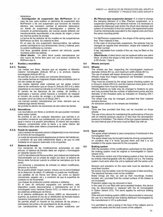
33
ANEXO «J» VEHÍCULOS DE PRODUCCIÓN DEL GRUPO NAPPENDIX “J” PRODUCTION CARS GROUP N
hidráulicos.- Amortiguador de suspensión tipo McPherson: En el
caso de que, para sustituir un elemento de suspensión tipo McPherson o de una suspensión que funcione de manera idéntica, sea necesario cambiar el elemento telescópico y/o tirante de suspensión (amortiguador y sistema de conexión al portamangueta), las nuevas piezas deberán ser mecánicamente equivalentes a las piezas de origen y tener los mismos puntos de anclaje.La forma de los asientos de los muelles en las suspensiones McPherson es libre. Su material es libre.En el caso de una suspensión oleoneumática, las esferas podrán cambiarse en sus dimensiones, forma y material, pero no podrá modificarse su número.Una llave, ajustable desde el exterior del vehículo, puede montarse sobre las esferas.
- Silent blocks: Un silent block puede reemplazarse por otro nuevo de forma libre pero con una dureza máxima de 80Shore–tipo A.
6.4 Ruedas y neumáticos6.4.1) Ruedas:
Las ruedas son libres, siempre que se respeten el diámetro máximo homologado (Artículo 801.a) y la anchura máxima homologada (Artículo 801.b).Se permite el uso de ruedas con menores dimensiones.Las ruedas hechas en magnesio forjado están prohibidas (aun si son las ruedas de origen).Las ruedas deberán estar cubiertas por las aletas (mismo sistema de verificación que en Grupo A, Artículo 255.5.4) y debe respetarse la vía máxima indicada en la Ficha de Homologación.El cambio de las fijaciones de las ruedas, de tornillos a espárragos y tuercas, podrá hacerse a condición de respetar el número de puntos de anclaje y el diámetro de las partes roscadas como se indica en el Dibujo 254-1.Las tuercas pueden reemplazarse por otras, siempre que su material siga siendo ferroso.Se prohíbe la adición de extractores de aire sobre las llantas.
6.4.2) Neumáticos:Los neumáticos son libres a condición de que puedan montarse sobre estas ruedas.Se prohíbe el uso de cualquier dispositivo que permita a un neumático conservar sus prestaciones con una presión interna igual o menor a la presión atmosférica. El interior del neumático (espacio comprendido entre la llanta y la parte interior del neumático) debe estar relleno únicamente de aire.
6.4.3) Rueda de repuesto:La(s) rueda(s) de repuesto es(son) obligatoria(s) si se mencionan en la ficha de homologación.La rueda de repuesto podrá desplazarse al interior del habitáculo, a condición de que esté sólidamente fijada y de que no esté instalada en el espacio reservado a los ocupantes.
6.5 Sistema de frenadoCon excepción de las modificaciones autorizadas en este artículo, el sistema de frenado debe ser original u homologado en Variante Opción (VO).La ECU del sistema de frenos es libre, pero deberá ser totalmente intercambiable con la unidad de origen (es decir, el sistema de frenos debe funcionar cuando la unidad se reemplace por la de serie).Los sensores y actuadores de entrada no deben modificarse, tampoco su función.No se podrá añadir ningún sensor, incluso con la única finalidad de la obtención de datos. El cableado no puede ser modificado.Las pastillas de los frenos son libres, así como su fijación (remachado, pegado, etc.), a condición de que la superficie de contacto no se incremente.Las chapas de protección podrán retirarse o doblarse.En el caso de vehículos equipados con servofreno, este dispositivo puede desconectarse o reemplazarse por el kit homologado como Variante Opción (VO). Lo mismo se aplica a los sistemas antibloqueo de frenos.Si el sistema antibloqueo de frenos (ABS) se desconecta o suprime, se autoriza el uso de un distribuidor de frenada trasera mecánico homologado por el fabricante como VO.Se permite añadir un resorte en los pistones de las pinzas y reemplazar las juntas y los guardapolvos de las pinzas.Las canalizaciones de los frenos pueden sustituirse por
- Mc Pherson type suspension damper: If, in order to change the damping element of a Mac Pherson suspension, or a suspension operating in an identical manner, it is necessary to replace the telescopic part and/or the shock strut (damper and system of connection to the hub carrier), the replacement parts must be mechanically equivalent to the original ones and have the same mounting points.
For McPherson suspensions, the shape of the spring seats is free. Their material is free. In the case of oil-pneumatic suspension, the spheres may be changed as regards their dimension, shape and material, but not their number.A tap, adjustable from outside of the car, may be fitted on the spheres.
- Silent blocks: A silent block may be replaced witha new silent block, of which the shape is free and the maximum hardness is 80 shores –Type A.
6.4 Wheels and tyres6.4.1) Wheels:
The wheels are free, respecting the homologated maximum diameter (Article 801.a), and maximum width (Article 801.b).The use of wheels with lesser dimensions is permitted.Wheels made from forged magnesium are forbidden (including standard wheels).They must be covered by the wings (same checking system as in Group A, Article 255-5.4), and the maximum track given on the homologation form must be respected.Wheels fixations by bolts may be changed to fixations by pins and nuts provided that the number of attachment points and the diameter of the threaded parts as indicated on Drawing 254-1 are respected.The wheel nuts may be changed, provided that their material remains ferrous.Air extractors added on the wheels are forbidden.
6.4.2) Tyres:Tyres are free provided that they can be mounted on those wheels.The use of any device for maintaining the performance of the tyre with an internal pressure equal to or less than the atmospheric pressure is forbidden. The interior of the tyre (space between the rim and internal part of the tyre) must be filled only with air.
6.4.3) Spare wheel:The spare wheel (wheels) is (are) compulsory if mentioned in the homologation form.The spare wheel may be brought inside the driving compartment, on condition that it is firmly secured there and that it is not installed in the space reserved for the occupants.
6.5 Braking systemWith the exception of the modifications authorised by this article, the braking system must be original or homologated in Option Variant (VO).The electronic control unit of the braking system is free, but must be entirely interchangeable with the original unit (i.e. the braking system must work when the unit is replaced with the series unit).
Sensors and actuators on the input side must be standard, as must their function.No sensor may be added, even for the purpose of data recording. The electrical harness must not be modified.Brake linings are free, as well as their mountings (riveted, bonded, etc.) provided that the contact surface of the brakes is not increased.Protection plates may be removed or bent.In the case of a car fitted with servo-assisted brakes, this device may be disconnected or replaced with the kit homologated in Option Variant (VO). The same applies for anti-lock braking systems.If the anti-lock braking system (ABS) is disconnected or removed, the use of a mechanical rear braking distributor homologated by the manufacturer in VO is authorised.
It is permitted to add a spring in the bore of the calipers and to replace the seals and the dust covers of the callipers.
34
ANEXO «J» VEHÍCULOS DE PRODUCCIÓN DEL GRUPO NAPPENDIX “J” PRODUCTION CARS GROUP N
canalizaciones de tipo aviación.Se puede añadir un dispositivo para eliminar el barro que se acumule sobre los discos de freno y/o las llantas.
6.5.1) Freno de mano:Puede reemplazarse el freno de mano mecánico por un sistema hidráulico homologado en Grupo N, pero, en este caso, un circuito de frenos en diagonal (en X) o el sistema original es obligatorio. Se permite modificar la posición del freno de mano hidráulico, siempre que permanezca en el emplazamiento homologado en Grupo N (en el túnel central, etcétera).
6.6 DirecciónLas canalizaciones que unen la bomba de dirección asistida a la cremallera de dirección pueden reemplazarse por canalizaciones que cumplan con las disposiciones del Artículo 253-3.2.
6.7 Carrocería6.7.1) Exterior:
Los tapacubos de las ruedas deben retirarse.Se pueden montar protectores de faros, siempre que su única función sea cubrir el vidrio del faro, sin influir en la aerodinámica del vehículo.El montaje de protecciones inferiores solo se autoriza en rallyes, a condición de que sean realmente protecciones que respeten la altura mínima al suelo, que sean desmontables y que estén concebidas exclusiva y específicamente con el fin de proteger los elementos siguientes: motor, radiador, suspensión, caja de cambios, depósito, transmisión, dirección, escape y botellas de los extintores.Las protecciones inferiores pueden extenderse toda la anchura de la parte inferior del parachoques delantero solamente por delante del eje delantero.Los puntos de anclaje de los parachoques delantero y trasero no pueden modificarse. Está permitido añadir fijaciones suplementarias (además de las de origen que se deben conservar) para fijar elementos de carrocería (parachoques, extensiones de aletas…).Se puede prever cualquier sistema de cierre del tapón del depósito de combustible. Se autoriza el cambio de las escobillas limpiaparabrisas delanteras y traseras.Las piezas de insonorización en plástico pueden retirarse del interior de los pasos de rueda. Esas piezas de plástico pueden reemplazarse por componentes de aluminio o de plástico con la misma forma.Pueden retirarse los elementos de protección en plástico fijados bajo la carrocería (recorridos por el flujo de aire).
6.7.2) Interior:El material de los asientos del piloto y copiloto es libre, pero el peso de la carcasa desnuda (el asiento sin la espuma ni los soportes) debe ser superior a 4 kg.Los asientos delanteros pueden retrasarse pero no más allá del plano vertical definido por el borde delantero del asiento trasero de origen.El límite relativo al asiento delantero está constituido por la altura del asiento sin reposacabezas; si el reposacabezas está integrado en el asiento, por la parte que se encuentre más atrás de los hombros del conductor.Los asientos traseros pueden retirarse.Los cinturones de seguridad traseros pueden retirarse.
6.7.2.1) Si el depósito estuviera instalado en el maletero y los asientos hubieran sido retirados, un panel resistente al fuego y estanco deberá separar el habitáculo del depósito.En el caso de un vehículo de dos volúmenes, será posible utilizar un panel o carcasa, no estructural, ignífugo, hecho de plástico transparente, situado entre el habitáculo y la ubicación del depósito.
6.7.2.2) Salpicadero:El salpicadero y la consola central deben permanecer de origen.
6.7.2.3) Puertas y revestimientos laterales:Se permite retirar el material de insonorización de las puertas, siempre que no se modifique su aspecto.
a) Se permite retirar el guarnecido de las puertas así como las barras de protección lateral con el fin de instalar un panel de protección lateral construido en material compuesto no inflamable. La configuración mínima de este panel deberá ser conforme al Dibujo 255-14.
b) En caso de que la estructura original de las puertas no haya sido modificada (supresión aunque sea parcial de las barras o de los
Brake lines may be changed for aviation type lines.A device for scraping away the mud which collects on the brake discs and / or the wheels may be added.
6.5.1) Handbrake:The mechanical handbrake may be replaced with a hydraulic system homologated in Group N, but in this case a diagonal brake circuit (X shape) or the original system is mandatory. It is permitted to modify the position of the hydraulic handbrake system, provided that it remains in the location homologated in Group N (on the central tunnel …).
6.6 SteeringThe lines linking the power steering pump to the rack may be replaced with lines conforming to Article 253-3.2.
6.7 Bodywork6.7.1) Exterior :
Hubcaps must be removed.Protective headlight covers may be fitted provided that their only function is to cover the glass, and that they have no influence on the car’s aerodynamics.The fitting of underbody protections is authorised in rallies only, provided that these really are protections which respect the ground clearance, which are removable and which are designed exclusively and specifically in order to protect the following parts: engine, radiator, suspension, gearbox, tank, transmission, steering, exhaust, extinguisher bottles.Underbody protections may extend the whole width of the underside part of the font bumper only in front of the front wheel axis.The mountings of the front and rear bumpers cannot be modified. Additional mountings are authorised (in addition to the original mountings which must be retained) for attaching bodywork parts (bumper, wing extensions...)Any locking system may be used for the cap of the petrol tank.The changing of the front and rear windscreen wiper blades is authorised.Plastic sound-proofing parts may be removed from the wheel openings. These plastic elements may be changed for aluminium or plastic elements of the same shape.
Plastic protection parts fitted under the body (licked by the air flow) may be removed.
6.7.2) Interior:The material of the driver’s and co-driver’s seats is free but the weight of the bare shell (seat without foam or supports) must be more than 4 kg.The front seats may be moved backwards but not beyond the vertical plane defined by the front edge of the original rear seat.The limit relating to the front seat is formed by the height of the seat without the headrest, and if the headrest is incorporated into the seat, by the rearmost point of the driver’s shoulders.The rear seats may be removed.The rear safety belts may be removed.
6.7.2.1) Should the fuel tank be installed in the boot and the rear seats removed, a fireproof and liquid-proof bulkhead must separate the cockpit from the fuel tank.
In the case of twin-volume cars it will be possible to use a non-structural partition wall in transparent, non-flammable plastic between the cockpit and the tank arrangement.
6.7.2.2) Dashboard:The dashboard and the central console must remain original.
6.7.2.3) Doors - Side trim:It is permitted to remove the soundproofing material from the doors, provided that this does not modify the shape of the doors.
a) It is permitted to remove the trim from the doors together with their side protection bars in order to install a side protection panel which is made from non-inflammable composite materials. The minimum configuration of this panel must comply with that shown on Drawing 255-14.
b) If the original structure of the doors has not been modified (removal, even partially, of the tubes or reinforcements), the door
35
ANEXO «J» VEHÍCULOS DE PRODUCCIÓN DEL GRUPO NAPPENDIX “J” PRODUCTION CARS GROUP N
refuerzos), los paneles de las puertas pueden hacerse de chapa metálica de 0,5 mm de espesor mínimo, de fibra de carbono de al menos 1 mm de espesor o de otro material sólido y no inflamable de 2 mm de espesor como mínimo.Las normas antes mencionadas se aplican igualmente para los revestimientos situados bajo las ventanas laterales traseras en los vehículos de dos puertas.La altura mínima del panel de protección lateral de las puertas debe extenderse desde la base de la puerta hasta la altura máxima de la traviesa de la puerta.Se permite sustituir un elevalunas eléctrico por un elevalunas manual.Se permite sustituir un elevalunas manual por un elevalunas eléctrico.
6.7.2.4) Suelo:Las alfombrillas son libres y, por lo tanto, pueden retirarse.
6.7.2.5) Otros materiales de insonorización y guarnecidos:Se permite retirar los materiales de insonorización y los guarnecidos, excepto los mencionados en los Artículos 6.7.2.3. (Puertas) y 6.7.2.2. (Salpicadero).
6.7.2.6) Sistema de calefacción:El sistema de calefacción de origen debe mantenerse.Pueden quitarse los siguientes elementos del aire acondicionado: condensador y ventilador auxiliar, depósito del fluido, evaporador y ventilador del evaporador, válvula de expansión, así como todos los tubos, las conexiones, interruptores de contacto, sensores y actuadores necesarios para el funcionamiento del sistema.Solo si el sistema de accionamiento es completamente independiente de cualquier otro dispositivo, puede retirarse el compresor del aire acondicionado. Si ese no es el caso, la eliminación del compresor del aire acondicionado debe ser homologada como VO. El compresor puede dejarse inoperante.Si ciertos elementos son comunes al sistema de calefacción, deben mantenerse.
6.7.2.7) Puede retirarse la bandeja trasera desmontable de los vehículos de dos volúmenes.
6.7.3) Accesorios adicionales:Se autorizan, sin restricciones, todos los accesorios que no tengan ningún efecto sobre el comportamiento del vehículo, tales como los que afectan a la estética o a la comodidad interior (iluminación, calefacción, radio, etcétera). Estos accesorios no podrán, en ningún caso, ni siquiera indirectamente, aumentar la potencia del motor o tener influencia sobre la dirección, la transmisión, los frenos o la estabilidad.La función de todos los mandos deberá ser la prevista por el constructor. Se permite adaptarlos para hacerlos más utilizables o más fácilmente accesibles, como por ejemplo, una palanca del freno de mano más larga, una placa adicional en el pedal de freno, etcétera.Se permite lo siguiente:
1) Los instrumentos de medición, velocímetros, etc., pueden instalarse o sustituirse, con funciones eventualmente diferentes. Tales instalaciones no deben entrañar riesgos. Sin embargo, el velocímetro no podrá retirarse, si el reglamento particular de la prueba lo prohíbe.
2) La bocina puede cambiarse y/o añadirse otra adicional al alcance del pasajero.La bocina no es obligatoria en carreteras cerradas.
3) El mecanismo de bloqueo de la palanca de freno de mano puede cambiarse con el fin de obtener un desbloqueo instantáneo (freno de mano «fly-off»).
4) El volante de la dirección es libre.El sistema de bloqueo antirrobo de dirección puede dejarse inoperante.El mecanismo de retirada rápida del volante debe consistir en un collarín concéntrico con respecto al eje del volante, coloreado de amarillo por anodización o por cualquier otro revestimiento duradero, e instalado en la columna de dirección por detrás del volante.El sistema de retirada debe ser accionado tirando del collarín siguiendo el eje de la dirección.
5) Se permite añadir compartimentos suplementarios a la guantera y bolsillos adicionales en las puertas, siempre que se usen los paneles de origen.
6) Se pueden añadir paneles de material aislante para proteger a los pasajeros o las piezas del fuego o del calor.
panels may be made from metal sheeting at least 0.5 mm thick, from carbon fibre at least 1 mm thick or from another solid and non-combustible material at least 2 mm thick.
The rules mentioned above also apply to the trim situated beneath the rear side windows of two-door cars.
The minimum height of the door’s side protection panel must extend from the base of the door to the maximum height of the door strut.It is permitted to replace electric winders with manual ones.
It is permitted to replace manual winders with electric ones.
6.7.2.4) Floor :Carpets are free and may thus be removed.
6.7.2.5)Othersound-proofingmaterialsandtrim:Other soundproofing materials and trim, except for those mentioned under Articles 6.7.2.3 (Doors) and 6.7.2.2 (Dashboard), may be removed.
6.7.2.6) Heating system:The original heating equipment must be retained.The following parts of the air conditioning system may be removed: condenser and auxiliary fan, fluid tank, evaporator and fan, expansion valve, as well as all pipes, connections, contact switches, sensors and actuators necessary for the functioning of the system.Only if its drive system is completely independent of any other system will it be possible to remove the air conditioning compressor. If that is not the case, the removal of the air conditioning compressor must be homologated in VO. The compressor may be rendered inoperative.If certain elements are common with the heating system, they must be retained.
6.7.2.7) The removable rear shelf in twin-volume cars may be removed.
6.7.3) Additional accessoriesAll those which have no influence on the car’s behaviour, for example equipment which improves the aesthetics or comfort of the car interior (lighting, heating, radio, etc.), are allowed without restriction. In no case may these accessories increase the engine power or influence the steering, transmission, brakes, or roadholding, even in an indirect fashion.
All controls must retain the role laid down for them by the manufacturer. They may be adapted to facilitate their use and accessibility, for example a longer handbrake lever, an additional flange on the brake pedal, etc.
The following is allowed:1) Measuring instruments such as speedometers etc. may be
installed or replaced, and possibly have different functions. Such installations must not involve any risk. However, the speedometer may not be removed if the supplementary regulations of the event prevent this.
2) The horn may be changed and/or an additional one added, within reach of the passenger.The horn is not compulsory on closed roads.
3) The handbrake locking mechanism may be removed in order to obtain instant unlocking (fly-off handbrake).
4) The steering wheel is free.The locking system of the anti-theft steering lock may be rendered inoperative.The quick release mechanism must consist of a flange concentric to the steering wheel axis, coloured yellow through anodisation or any other durable yellow coating, and installed on the steering column behind the steering wheel.The release must be operated by pulling the flange along the steering wheel axis.
5) Additional compartments may be added to the glove compartment and additional pockets in the doors, provided that they use the original panels.
6) Insulating material may be added to protect the passengers or parts from fire or heating.
36
ANEXO «J» VEHÍCULOS DE PRODUCCIÓN DEL GRUPO NAPPENDIX “J” PRODUCTION CARS GROUP N
6.7.4) Refuerzos:Pueden montarse barras de refuerzo sobre los puntos de anclaje de la suspensión a la carrocería o al chasis de un mismo eje, a cada lado del eje longitudinal del vehículo, a condición de que sean desmontables y atornilladas.La distancia entre un punto de anclaje de la suspensión y un punto de anclaje de la barra debe ser inferior a 100 mm, a menos que la barra sea un refuerzo transversal homologado con la estructura de seguridad, o salvo en el caso de una barra superior fijada a una suspensión McPherson o similar.En este último caso, la distancia máxima entre un punto de anclaje de la barra y el punto de articulación superior debe ser de 150 mm (Dibujos 255-2 y 255-4).Fuera de estos puntos, esta barra no debe anclarse sobre la carrocería o los elementos mecánicos.Si el vehículo de serie está equipado con una barra de refuerzo, se permite quitar o reemplazar la barra de serie por una barra conforme a las prescripciones antes mencionadas.Se permite el refuerzo de la parte suspendida, a condición de que el material utilizado siga la forma original y esté en contacto con ella.
6.7.5) Cuando la rueda de repuesto esté situada originalmente en un alojamiento cerrado y esta rueda se sustituya por una más gruesa (ver Artículo 6.4) situada en ese alojamiento, será posible eliminar de la tapa del alojamiento de la rueda la superficie inducida por el diámetro de la nueva rueda (Dibujo 254-2).
6.8 Sistema eléctrico- Batería: La marca, la capacidad y los cables de la batería son
libres. La tensión y el emplazamiento de la batería deben conservarse. Se permite un desconectador de la batería en el habitáculo.
- Generador: Se autoriza la sustitución por un generador de mayor potencia. Una dinamo no puede sustituirse por un alternador, ni viceversa.
- Sistema de iluminación: Se autorizan 6 faros suplementarios como máximo, incluidos sus relés correspondientes, siempre que lo permitan las leyes del país. Si se conservan los faros antiniebla de serie, se contabilizarán como faros adicionales.No se podrán instalar por empotramiento. El número de faros y luces exteriores deberá ser siempre par.Los faros de origen pueden dejarse inoperantes y pueden cubrirse con cinta adhesiva. Pueden reemplazarse por otros, a condición de que se respeten las disposiciones de este artículo.Está autorizado el montaje de una luz de marcha atrás con la condición de que solo pueda utilizarse cuando la palanca de cambios se encuentre en la posición de «marcha atrás» y siempre que se respeten las leyes de tráfico.
- Se permite añadir fusibles al circuito eléctrico.6.9 Circuito de combustible
Si el depósito de origen está equipado con una bomba eléctrica y un filtro interior, y si se trata de un depósito FT3 1999, FT3.5, FT5 o de algún otro depósito homologado por el fabricante en la Ficha de Homologación del vehículo, es posible colocar, en la parte exterior, un filtro y una bomba de características idénticas a la homologada. Se permite utilizar un depósito de tipo FT3 1999, FT3.5 o FT5 como complemento del depósito de serie (deben respetarse las condiciones indicadas a continuación).Estas piezas deberán estar protegidas de forma adecuada.Se permite el montaje de una segunda bomba de combustible, pero debe ser únicamente una bomba de repuesto, es decir, no puede funcionar junto con la bomba autorizada. Solo debe conectarse cuando el vehículo esté inmóvil y por medio de un sistema puramente mecánico, situado junto a las bombas. Los orificios de llenado no podrán estar situados en las lunas.Las canalizaciones de combustible deben reemplazarse por canalizaciones del tipo de aviación si se usa un depósito FT3 1999, FT3.5 o FT5; el recorrido de dichas canalizaciones es libre.En el caso de utilizar el depósito de serie, este cambio es opcional.Se permite taladrar 2 orificios (diámetro máximo de 60mm o superficie equivalente) en el suelo, cuya única función será dejar pasar las canalizaciones necesarias para el llenado/ventilación del depósito de combustible.La capacidad total de los depósitos no debe exceder la indicada
6.7.4) ReinforcementsReinforcement bars may be fitted on the suspension mounting points to the bodyshell or chassis of the same axle, on each side of the car’s longitudinal axis, on condition that they are removable and are attached by means of bolts.The distance between a suspension attachment point and an anchorage point of the bar cannot be more than 100 mm, unless the bar is a transverse strut homologated with the safety cage, or unless it is an upper bar attached to a MacPherson suspension or similar.In the latter case, the maximum distance between an anchorage point of the bar and the upper articulation point will be 150 mm (Drawings 255-2 and 255-4).Apart from these points, this bar must not be mounted on the bodyshell or the mechanical parts.If the series vehicle is equipped with a reinforcement bar, it is permitted to remove or replace the series bar with a bar conforming to the prescriptions mentioned above.Strengthening of the suspended part is allowed provided that the material used follows the original shape and is in contact with it.
6.7.5) When the spare wheel is originally set in a closed accommodation, and when this wheel is changed for a thicker one (see Article 6.4), situated in this space, it is possible to remove from the cover of the location of the wheel the surface induced by the diameter of the new wheel (Drawing 254-2).
6.8 Electrical system- Battery: The make, capacity, and battery cables are free.
The tension and the site of the battery must be retained.A power take-off connected to the battery is permitted in the passenger space.
- Generator: May be replaced by a more powerful one. A dynamo may not be replaced by an alternator and vice-versa.
- Lighting system: A maximum of 6 additional headlights including the corresponding relays are allowed, provided that this is accepted by the laws of the country. If the series fog lamps are kept, they will be counted as additional headlights.They may not be housed within the bodywork. Headlights and other exterior lights must always exist in pairs.The original headlights can be made inoperative and covered with adhesive tape. They can be replaced by other headlights, in compliance with this article.A reversing light may be fitted provided it can only be used when the gear lever is in the "reverse" position, and provided that the police regulations on this subject are observed.
- Fuses may be added to the electrical system.
6.9 Fuel circuitProviding the original tank is equipped with an electric pump and an interior filter, it is possible when using an FT3 1999, FT3.5 or FT5 tank or another tank homologated by the manufacturer on the car’s homologation form to place a filter and a pump with identical characteristics to the homologated one outside.
An FT3 1999, FT3.5 or FT5 type tank may be used to supplement the series tank (the conditions below must be respected).
These parts must be protected in adequate fashion.The fitting of a second fuel pump is authorised, but this must be only a spare fuel pump, i.e. it cannot operate in addition to the authorised pump. It must be connectable only when the car is immobile and by means of a purely mechanical device situated beside the pumps. The filler holes may not be located in the window panels.
Fuel lines must be changed for aviation type lines if an FT3 1999, FT3.5 or FT5 tank is used, the route of these lines being free.
Should a series production tank be used, this change is optional.
It is authorised to drill 2 holes (maximum diameter of 60mm or equivalent area) in the floor, the sole function of which will be to allow the passage of the lines necessary to feed / empty the fuel tank.
37
ANEXO «J» VEHÍCULOS DE PRODUCCIÓN DEL GRUPO NAPPENDIX “J” PRODUCTION CARS GROUP N
en el Artículo 401.d de la Ficha de Homologación de Grupo N, excepto en rallyes si el vehículo está equipado con depósitos FT3 1999, FT3.5 o FT5.En este caso, la capacidad total de los depósitos de carburante no debe exceder los límites siguientes en función de la cilindrada del motor:Hasta 700 cm3: 60 lMás de 700 cm3 hasta 1.000 cm3: 70 lMás de 1.000 cm3 hasta 1.400 cm3: 80 lMás de 1.400 cm3: 95 lPara vehículos de dos volúmenes homologados a partir del 01/01/98, con un depósito de combustible instalado en el maletero, una caja resistente al fuego y estanca debe rodear al depósito de combustible y sus orificios de llenado.En los vehículos de tres volúmenes homologados desde el 01/01/98, un panel ignífugo y estanco deberá separar el habitáculo del depósito de combustible.No obstante, se recomienda que este panel estanco se sustituya por una caja estanca como en los vehículos de dos volúmenes.
6.10 Gato y atornillador automáticoLos puntos de levantamiento pueden reforzarse, trasladarse o aumentarse su número. Estas modificaciones están limitadas exclusivamente a los puntos de levantamiento. El gato debe funcionar de modo exclusivamente manual (accionado por el piloto o bien por el copiloto), es decir, sin ayuda de ningún sistema equipado con una fuente de energía hidráulica, neumática o eléctrica.El atornillador automático no debe permitir el desmontaje simultáneo de más de una tuerca.
6.11 Estructura de seguridadLa estructura de cualquier vehículo con una cilindrada corregida superior a 2000 cm3 homologado con posterioridad al 01/01/2006 debe estar homologada o certificada por una ADN, u homologada por la FIA.
ARTÍCULO 7 - VEHÍCULOS CON UNA CILINDRADA CORREGIDA SUPERIOR A 2 LITROS EN RALLYES
Los siguientes artículos se aplicarán únicamente a los vehículos que participen en rallyes con una cilindrada corregida superior a 2 litros como complemento de todos los artículos anteriores. Si alguno de los siguientes artículos estuviera en contradicción con alguno de los artículos anteriores (Artículos 1 a 6), los artículos mencionados a continuación prevalecerán para los vehículos con una cilindrada corregida superior a los 2 litros.7.1 Peso mínimo (solamente para los vehículos con cuatro
ruedas motrices)a) Para los vehículos homologados después del 01/01/2006,
el peso mínimo se ha fijado en 1350kg con las condiciones siguientes:- Es el peso real del vehículo, sin piloto ni copiloto, ni su
equipamiento y con un máximo de una rueda de repuesto.- en el caso de llevar a bordo 2 ruedas de repuesto, la segunda
rueda deberá ser retirada antes del pesaje.En ningún momento de la prueba, un vehículo podrá pesar menos que este peso mínimo.En caso de disputa durante el pesaje, debe retirarse todo el equipamiento del piloto y copiloto, incluso el casco, pero los auriculares externos al casco podrán dejarse en el vehículo.Se permite utilizar lastre en las condiciones previstas por el Artículo 252-2.2 de las «Prescripciones Generales».
b) El peso mínimo del vehículo (bajo las condiciones del Artículo 7.1.a) con el equipo a bordo (piloto + copiloto + equipamiento completo del piloto y el copiloto) es: Peso mínimo definido en el Artículo 7.1a + 150kg.
7.2 Motor7.2.1) Adquisición de datos
Se autoriza un sistema de adquisición de datos, incluso si el vehículo de serie no lo equipa.Debe estar conectado únicamente a:- Los sensores de serie- Se permite añadir los siguientes sensores: temperatura de
agua, temperatura de aceite, presión de aceite y régimen del motor.
Se prohíbe cualquier intercambio de datos con el vehículo excepto mediante una conexión por cable o una tarjeta.
7.2.2) Sistema «anti-lag»Se permite añadir un interruptor y un cableado eléctrico con el
The total capacity of the tanks must not exceed that indicated in Article 401d of the Group N Homologation Form, except for rallies, if the car is fitted with FT3 1999, FT3.5 or FT5 tanks.In this case, the total capacity of the tanks must not exceed the following limits, in relation to the engine capacity:
up to 700 cm3: 60 lover 700 cm3 and up to 1.000 cm3: 70 lover 1000 cm3 and up to 1.400 cm3: 80 lover 1.400 cm3: 95 lFor twin-volume cars homologated from 01.01.98 with a fuel tank installed in the luggage compartment, a fireproof and liquid-proof case must surround the fuel tank and its filler holes.
For three-volume cars homologated from 01.01.98, a fireproof and liquid-proof bulkhead must separate the cockpit from the fuel tank.Nevertheless, it is recommended that this liquid-proof bulkhead be replaced by a liquid-proof case as for twin-volume cars.
6.10 Jack and wheel gunThe jacking points may be strengthened, moved and increased in number. These modifications are limited exclusively to the jacking points. The jack must be operated exclusively by hand (either by the driver, or by the co-driver), i.e. without the help of a system equipped with a hydraulic, pneumatic or electric energy source.
The wheel gun must not allow the removal of more than one nut at a time.
6.11 Safety cageThe cage of any car with a corrected cylinder capacity greater than 2000 cm3, homologated after 01/01/2006 must be homologated or certified by an ASN, or homologated by the FIA.
ARTICLE 7 - CARS WITH A CORRECTED CYLINDER CAPACITY GREATER THAN 2L IN RALLY
The following articles apply only to cars taking part in Rally with a corrected cylinder capacity greater than 2L and are complementary to the preceding articles. In case of contradiction between any of the following articles and the preceding articles (articles 1 to 6), the articles mentioned below will take priority for cars with a corrected cylinder capacity greater than 2L.
7.1 Minimum weight (only for cars with four-wheel drive)
a) For cars homologated after 01.01.2006, the minimum weight is set at 1350kg in the following conditions:- this is the real weight of the car, with neither driver nor co-driver
nor their equipment and with a maximum of one spare wheel;- when two spare wheels are carried in the car, the second
spare wheel must be removed before weighing.
At no time during the event may a car weigh less than this minimum weight.In case of dispute during weighing, the full equipment of the driver and co-driver will be removed; this includes the helmet, but the headphones external to the helmet may be left in the car.The use of ballast is permitted in the conditions provided for under Article 252-2.2 of the "General Prescriptions".
b) The minimum weight of the car (under the conditions of Article 7.1a) with crew (driver + co-driver + the full equipment of the driver and co-driver) will be: minimum weight defined by Article 7.1a + 150kg.
7.2 Engine
7.2.1) Data loggingA data logging system is authorised, even if the series vehicle is not so equipped.It must be connected only:- to the series sensors- to the following sensors which it will be possible to add: water
temperature, oil temperature, oil pressure and engine speed.Any exchange of data with the car by a method other than cable link or chip card is prohibited.
7.2.2) Anti-lag systemA switch and an electric loom may be added for the sole purpose
38
ANEXO «J» VEHÍCULOS DE PRODUCCIÓN DEL GRUPO NAPPENDIX “J” PRODUCTION CARS GROUP N
único propósito de activar el sistema «anti-lag».7.3 Transmisión7.3.1) Diferenciales delantero y trasero
Solo se autorizan diferenciales de tipo mecánico de deslizamiento limitado de discos. Los diferenciales de tipo mecánico de deslizamiento limitado de discos deben:- proceder del modelo de serie- o bien ser homologados como Variante Opción de Grupo N.Un diferencial de tipo mecánico de deslizamiento limitado es cualquier sistema que trabaja exclusivamente de modo mecánico, es decir, sin la asistencia de otro sistema hidráulico o eléctrico.Un acoplamiento viscoso no se considera un sistema mecánico.Se prohíbe cualquier diferencial con control electrónico.El número y el tipo de discos son libres.
7.3.2) LubricaciónCaja de cambios y diferencial: Se permite un sistema adicional de lubricación y de refrigeración del aceite siempre que esté homologado como Variante Opción.
7.4 Ruedas y neumáticosLas ruedas completas son libres a condición de que puedan alojarse en la carrocería de origen; esto significa que la parte superior de la rueda completa, situada verticalmente por encima del centro de la mangueta, debe estar cubierta por la carrocería cuando la medición se realiza verticalmente.El cambio de las fijaciones de las ruedas, de tornillos a espárragos y tuercas, es libre.Se prohíbe el uso de neumáticos de motocicleta.Las llantas deben estar hechas obligatoriamente de material de fundición o de chapa de acero embutida.*Para los rallyes de tierra, la dimensión máxima de las llantas es de 7" x 15".Si las llantas no son de aluminio fundido, el peso mínimo de una llanta de 6,5" x 15" o de 7" x 15" es de 8,6 kg.*Si está admitido en el reglamento particular de la prueba (como en los rallyes de nieve), la dimensión máxima de las llantas es de 5,5" x 16".*Para los rallyes de asfalto:
- la dimensión máxima de las llantas es de 8" x 18";- el material de las llantas de 8"x18" es libre (a condición de
que sean de fundición);- el peso mínimo de una llanta de 8"x18" es de 8,9 kg;- se prohíbe la adición de extractores de aire sobre las llantas.
7.5 Lunas traserasEn el caso de vehículos de 4 o 5 puertas, el mecanismo del elevalunas de las ventanillas traseras podrá reemplazarse por un dispositivo destinado a bloquear las ventanillas en posición cerrada.
MODIFICACIONES APLICABLES A PARTIR DEL 01/01/2013
5.2 En rallyes únicamente, el peso mínimo del vehículo (bajo las condiciones del Artículo 5,1) con el equipo a bordo (piloto + copiloto + equipamiento completo del piloto y del copiloto) será: Peso mínimo definido en el Artículo 5.1 + 150 kg 160 kg. En cualquier caso, el peso definido por el Artículo 5.1 debe respetarse también.
of activating the anti-lag system.7.3 Transmission7.3.1) Front and rear differentials
Only mechanical type limited-slip differentials with plates are authorised. Mechanical type limited-slip differentials with plates must:- either come from the series model- or be homologated as a Group N Option Variant.A mechanical limited-slip differential is any system that works exclusively mechanically, that is, without the assistance of a hydraulic or electric system.A viscous clutch is not considered as a mechanical system.
Any differential with electronic management is prohibited.The number and the type of the plates are free.
7.3.2) LubricationGearbox and differential: An additional lubrication and oil cooling device is allowed provided it is homologated in Option-Variant (VO).
7.4 Wheels and TyresComplete wheels are free, provided that they can be housed within the original bodywork; this means that the upper part of the complete wheel, located vertically over the wheel hub centre, must be covered by the bodywork when measured vertically.
Wheel fixations by bolts may be freely changed to fixations by pins and nuts.The use of tyres intended for motorcycles is forbidden.
Rims must imperatively be made from cast material, or from pressed steel sheet.*For gravel rallies, the maximum dimension of the rims is 7" x 15".If the rims are not made from cast aluminium alloy, the minimum weight of a 6.5" x 15" or 7" x 15" is 8.6 kg.
*If specified in the Supplementary Regulations of the event (such as snow rallies), the maximum dimension of the rims is 5.5" x 16".*For asphalt rallies:
- the maximum dimension of the rims is 8" x 18".- the material of the 8" x 18" rims is free (provided that it is
cast)- the minimum weight of an 8" x 18" rim is 8.9 kg- air extractors added on to the wheels are prohibited.
7.5 Rear windowsIn the case of cars with 4 or 5 doors, the lift mechanism for the rear windows may be replaced with a device that locks the rear windows in the closed position.
MODIFICATIONS APPLICABLES ON 01.01.2013
5.2 In rallies only, the minimum weight of the car (under the conditions of Article 5.1) with crew (driver + co-driver + the full equipment of the driver and co-driver) will be: Minimum weight defined by Article 5.1 + 150 kg 160 kg. Furthermore, the weight defined in Article 5.1 must also be respected.
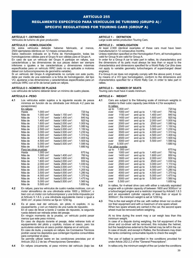
39
ARTÍCULO 255REGLAMENTO ESPECÍFICO PARA VEHÍCULOS DE TURISMO (GRUPO A) /
SPECIFIC REGULATIONS FOR TOURING CARS (GROUP A)
ARTÍCULO 1 - DEFINICIÓNVehículos de turismo de gran producción.
ARTÍCULO 2 - HOMOLOGACIÓNDe estos vehículos deberán haberse fabricado, al menos, 2500 ejemplares idénticos en 12 meses consecutivos.Salvo restricción indicada en la Ficha de Homologación, todas las homologaciones válidas para el Grupo N son válidas para el Grupo A.En caso de que un vehículo del Grupo A participe en rallyes, sus características y las dimensiones de sus piezas deben ser siempre inferiores o iguales a las características y dimensiones máximas especificadas para un vehículo WRC (esto no es aplicable a motores diésel con turbocompresores de geometría variable).Si un vehículo del Grupo A originalmente no cumple con este punto, debe por medio de una extensión a la ficha de homologación, del tipo VO, ajustarse a las dimensiones y características especificadas para un vehículo WRC con el fin de tomar parte en rallyes.
ARTÍCULO 3 - NÚMERO DE PLAZASLos vehículos de turismo deberán tener un mínimo de cuatro plazas.
ARTÍCULO 4 - PESO4.1 Los vehículos están sujetos a la siguiente escala de pesos
mínimos en función de su cilindrada (ver Artículo 4.2 para las excepciones):En rallyes:Hasta 1.000 cm3 720 kgMás de 1.000 cm3 hasta 1.150 cm3: 790 kgMás de 1.150 cm3 hasta 1.400 cm3: 840 kgMás de 1.400 cm3 hasta 1.600 cm3: 920 kgMás de 1.600 cm3 hasta 2.000 cm3: 1.000 kgMás de 2.000 cm3 hasta 2500 cm3: 1.080 kgMás de 2.500 cm3 hasta 3.000 cm3: 1.150 kgMás de 3.000 cm3 hasta 3.500 cm3: 1.230 kgMás de 3.500 cm3 hasta 4.000 cm3: 1.310 kgMás de 4.000 cm3 hasta 4.500 cm3: 1.400 kgMás de 4.500 cm3 hasta 5.000 cm3: 1.500 kgMás de 5.000 cm3 hasta 5.500 cm3: 1.590 kgMás de 5.500 cm3 1.680 kgPara las otras pruebas:Hasta 1.000 cm3 670 kgMás de 1.000 cm3 hasta 1.400 cm3: 760 kgMás de 1.400 cm3 hasta 1.600 cm3: 850 kgMás de 1.600 cm3 hasta 2.000 cm3: 930 kgMás de 2.000 cm3 hasta 2500 cm3: 1.030 kgMás de 2.500 cm3 hasta 3.000 cm3: 1.110 kgMás de 3.000 cm3 hasta 3.500 cm3: 1.200 kgMás de 3.500 cm3 hasta 4.000 cm3: 1.280 kgMás de 4.000 cm3 hasta 4.500 cm3: 1.370 kgMás de 4.500 cm3 hasta 5.000 cm3: 1.470 kgMás de 5.000 cm3 hasta 5.500 cm3: 1.560 kgMás de 5.500 cm3 1.650 kg
4.2 En rallyes, para los vehículos de cuatro ruedas motrices, con un motor atmosférico de una cilindrada entre 1600 y 3000cm3, o bien con un motor con turbocompresor y una brida impuesta por el Artículo 5.1.8.3, y una cilindrada equivalente menor o igual a 3000 cm3, el peso mínimo se fija en 1230 kg.
4.3 Es el peso real del vehículo, sin piloto ni copiloto, ni su equipamiento, y con un máximo de una rueda de repuesto.En el caso de llevar a bordo 2 ruedas de repuesto, la segunda rueda deberá ser retirada antes del pesaje.En ningún momento de la prueba, un vehículo podrá pesar menos que este peso mínimo.En caso de disputa durante el pesaje, debe retirarse todo el equipamiento del piloto y copiloto, incluso el casco, pero los auriculares externos al casco podrán dejarse en el vehículo.En caso de duda, y excepto en rallyes, los Comisarios Técnicos podrán vaciar los depósitos que contengan líquidos consumibles para comprobar el peso.Se permite utilizar lastre en las condiciones previstas por el Artículo 252-2.2 de las «Prescripciones Generales».
4.4 En rallyes únicamente, el peso mínimo del vehículo (bajo las
ARTICLE 1 - DEFINITIONLarge scale series production Touring Cars.
ARTICLE 2 - HOMOLOGATIONAt least 2,500 identical examples of these cars must have been manufactured in 12 consecutive months.Unless restriction specified on the Homologation Form, all homologations valid for Group N are valid for Group A.In order for a Group A car to take part in rallies, its characteristics and the dimensions of its parts must always be less than or equal to the characteristics and dimensions specified for a World Rally Car (this does not apply to variable geometry turbochargers of supercharged diesel engines).If a Group A car does not originally comply with the above point, it must, by means of a VO type homologation, conform to the dimensions and characteristics specified for a World Rally Car, in order to take part in rallies.
ARTICLE 3 - NUMBER OF SEATSTouring cars must have 4 seats minimum.
ARTICLE 4 - WEIGHT4.1 Cars are subject to the following scale of minimum weights in
relation to their cubic capacity (see Article 4.2 for exception):In rallies:up to 1.000 cm3: 720 kgover 1000 cm3 and up to 1.150 cm3: 790 kgover 1150 cm3 and up to 1.400 cm3: 840 kgover 1400 cm3 and up to 1.600 cm3: 920 kgover 1600 cm3 and up to 2.000 cm3: 1.000 kgover 2000 cm3 and up to 2500 cm3: 1.080 kgover 2500 cm3 and up to 3.000 cm3: 1.150 kgover 3000 cm3 and up to 3.500 cm3: 1.230 kgover 3500 cm3 and up to 4.000 cm3: 1.310 kgover 4000 cm3 and up to 4.500 cm3: 1.400 kgover 4500 cm3 and up to 5.000 cm3: 1.500 kgover 5000 cm3 and up to 5.500 cm3: 1.590 kgover 5.500 cm3: 1.680 kgFor other events:up to 1.000 cm3: 670 kgover 1000 cm3 and up to 1.400 cm3: 760 kgover 1400 cm3 and up to 1.600 cm3: 850 kgover 1600 cm3 and up to 2.000 cm3: 930 kgover 2000 cm3 and up to 2500 cm3: 1.030 kgover 2500 cm3 and up to 3.000 cm3: 1.110 kgover 3000 cm3 and up to 3.500 cm3: 1.200 kgover 3500 cm3 and up to 4.000 cm3: 1.280 kgover 4000 cm3 and up to 4.500 cm3: 1.370 kgover 4500 cm3 and up to 5.000 cm3: 1.470 kgover 5000 cm3 and up to 5.500 cm3: 1.560 kgover 5.500 cm3: 1.650 kg
4.2 In rallies, for 4-wheel drive cars with either a naturally aspirated engine with a cylinder capacity of between 1600 and 3000cm3 or a turbocharged engine and a restrictor imposed by Article5.1.8.3 and an equivalent cylinder capacity of less than or equal to 3000cm3, the minimum weight is set at 1230 kg.
4.3 This is the real weight of the car, with neither driver nor co-driver nor their equipment and with a maximum of one spare wheel.When two spare wheels are carried in the car, the second spare wheel must be removed before weighing.
At no time during the event may a car weigh less than this minimum weight.In case of a dispute during weighing, the full equipment of the driver and co-driver will be removed; this includes the helmet, but the headphones external to the helmet may be left in the car.In case of doubt, and except in Rallies, the Scrutineers may drain the tanks containing consumable liquids to check the weight.
The use of ballast is permitted in the conditions provided for under Article 252-2.2 of the "General Prescriptions".
4.4 In rallies only, the minimum weight of the car (under the conditions
40
ANEXO «J» TURISMO GRUPO AAPPENDIX “J” TOURING CARS GROUP A
condiciones del Artículo 4.3) con el equipo a bordo (piloto + copiloto + equipamiento completo del piloto y del copiloto) será: Peso mínimo definido en el Artículo 4.1 + 150 kg.Para vehículos con cuatro ruedas motrices, en rallyes, con motor atmosférico de cilindrada comprendida entre 1600 y 3000 cm3, o motor turboalimentado con una brida impuesta por el Artículo5.1.8.3 junto con una cilindrada equivalente inferior o igual a 3000 cm3, el peso mínimo del vehículo (bajo las condiciones del Artículo 4.3) con el equipo a bordo (piloto + copiloto + equipamiento completo del piloto y el copiloto) será: 1.380 kg.En cualquier caso, el peso definido por los Artículos 4.1, 4.2 y 4.3 debe respetarse también.
ARTÍCULO 5 - MODIFICACIONES Y MONTAJES AUTORIZADOS - GENERALIDADES:
Independientemente de las piezas para las que el presente artículo prevé libertad de modificación, las piezas mecánicas de origen necesarias para la propulsión, así como todos los accesorios necesarios para su funcionamiento normal, y excepto toda pieza de la dirección, de los frenos o de la suspensión, que hayan sufrido todas las fases de fabricación previstas por el constructor para la producción en serie, pueden ser objeto de todas las operaciones de puesta a punto por acabado o rascado, pero no pueden ser sustituidas.En otras palabras, bajo reserva de que se pueda establecer indiscutiblemente el origen de la pieza de serie, esta podrá ser rectificada, equilibrada, ajustada, reducida o modificada por mecanizado.Además se autorizan los tratamientos químicos y térmicos.Sin embargo, las modificaciones definidas en el párrafo anterior están autorizadas con la condición de que respeten los pesos y dimensiones mencionados en la ficha de homologación.Tornillos y tuercas:En todo el vehículo, toda tuerca, perno o tornillo, podrá reemplazarse por otra tuerca, bulón o tornillo y tener cualquier tipo de bloqueo (arandela, contratuerca, etcétera).Adición de material y de piezas:Está prohibida cualquier adición o fijación de material o de piezas si no está expresamente autorizada por un artículo de este reglamento. El material retirado no podrá reutilizarse. Se permite restaurar la forma de la carrocería y la geometría del chasis, después de un accidente, añadiendo los materiales necesarios para llevar a cabo la reparación (masilla para carrocería, metal aportado por soldadura, etc.); otras piezas que estén desgastadas o dañadas no podrán repararse por adición de material, a menos que un artículo de este reglamento lo autorice.5.1 Motor5.1.1) Bloque de cilindro - Culata:
Se permite cerrar las aberturas no utilizadas en el bloque de cilindros y en la culata, si el único fin de esta operación es el tapado.Se permite un rectificado máximo de 0,6 mm en relación con el diámetro de origen, sin que esto entrañe sobrepasar el límite de cilindrada para su clase.Se permite encamisar el motor, en las mismas condiciones que el rectificado, y puede modificarse el material de las camisas.Las camisas deben ser de sección circular interna y coaxial con cilindros, secas o húmedas, y diferentes entre ellas.Se permite el planificado del bloque y de la culata.En el caso de motores rotativos, las dimensiones de los conductos de admisión y de escape en el bloque son libres, a condición de respetar las dimensiones originales de los orificios de entrada de la admisión y de salida del escape.
5.1.2) Relación de compresión:Se permite modificar la relación de compresión. En el caso de motores turboalimentados, no debe superar 11,5:1 en ningún momento.Si el vehículo homologado supera esta relación, debe modificarse para no que no exceda 11,5:1 .
5.1.3) Junta de culata:Libre.
5.1.4) Pistones:Libres, así como los segmentos, los bulones y sus blocajes.
5.1.5) Bielas, cigüeñal:Aparte de las modificaciones permitidas por el anterior párrafo «Generalidades», el cigüeñal y las bielas de origen pueden ser
of Article 4.3) with crew (driver + co-driver + the full equipment of the driver and co-driver) will be: Minimum weight defined by Article 4.1 + 150 kg.For cars with four-wheel drive, in rallies, with either a naturally aspirated engine of a capacity between 1600 and 3000 cm3, or turbocharged engine with a restrictor imposed by Article 5.1.8.3 together with an equivalent capacity lower than or equal to 3000cm3, the minimum weight of the car (under the conditions of Article 4.3) with crew (driver + co-driver + the full equipment of the driver and co-driver) will be: 1.380 kg.Furthermore, the weights defined in Articles 4.1, 4.2 and 4.3 must also be respected.
ARTICLE 5 - MODIFICATIONS AND ADJUNCTIONS ALLOWED GENERAL CONDITIONS
Irrespective of the parts for which the present article lays down freedom of modification, the original mechanical parts necessary for the propulsion as well as all accessories necessary for their normal functioning, excepting any steering, braking, or suspension part, having undergone the normal machining operations laid down by the manufacturer for series production may be subjected to all tuning operations through finishing, scraping but not replacement.
In other words provided that the origin of the series production part may always be established, its shape may be ground, balanced, adjusted, reduced or modified through machining.Chemical and heat treatment are allowed, in addition to the above.However, the modifications defined by the above paragraph are allowed on condition that the weights and dimensions mentioned on the homologation form are respected.Nuts and bolts:Throughout the car, any nut, bolt, screw may be replaced by any other nut, any other bolt, any other screw and have any kind of locking device (washer, lock nut, etc.).Addition of material and parts:Any addition of material or parts is forbidden unless it is specifically allowed by an article in these regulations. Any material removed is not to be reused. Restoration of body shape and chassis geometry, following accidental damage, is permissible by the addition of the materials necessary to effect the repairs (body filler, weld metal, etc.) ; other parts which are worn or damaged are not to be repaired by the addition or attaching of material unless an article in these regulations allows appropriate freedom.
5.1 Engine5.1.1) Cylinder-block - Cylinder-head:
It is permitted to close the unused apertures in the cylinder block and cylinder head, if the only purpose of this operation is that of closing.A rebore of 0.6 mm maximum is allowed in relation to the original bore without this leading to the capacity class limit being exceeded.The resleeving of the engine is allowed within the same conditions as for reboring, and the sleeve material may be modified.The sleeves must have a circular internal section and be concentric with the cylinders, dry or wet and distinct from one another.Planing of the cylinder-block and of the cylinder head is allowed.In the case of rotary engines, on condition that the original dimensions of the intake inlet ports and of the exit of the exhaust are respected, the dimensions of the inlet and exhaust ducts into the engine block are free.
5.1.2) Compression ratio:The compression ratio may be modified. For turbocharged engines, it must not excee 11.5:1 at any time.If the car is homologated with a higher rate, it must be modified so as not to exceed 11.5:1.
5.1.3) Cylinder head gasket:Free.
5.1.4) Pistones:Free as well as the piston-rings, gudgeon pins and their securing mechanism.
5.1.5) Connecting rods, crankshaft:Apart from the modifications permitted by the above paragraph "General Conditions", additional mechanical treatments, different from those carried out on the series production part, are allowed
41
ANEXO «J» TURISMO GRUPO AAPPENDIX “J” TOURING CARS GROUP A
objeto de un tratamiento mecánico adicional diferente al previsto para las piezas de serie.
5.1.6) Cojinetes:La marca y el material son libres, pero deben conservar su tipo y las dimensiones de origen.
5.1.7) Volante de inercia:Se puede modificar de acuerdo con el anterior párrafo «Generalidades», con la condición de que sea aún posible reconocer el volante de origen.
5.1.8) Alimentación:Debe respetarse lo establecido por los Dibujos I y II (Dibujos III-K1 y III-K2 para los vehículos homologados a partir del 01/01/2010) de la Ficha de Homologación de Grupo A.El cable del acelerador y su tope de funda son libres.El filtro de aire así como su caja son libres.Para un motor atmosférico, la cámara de tranquilización es libre aunque debe estar montada en el compartimento motor.El filtro de aire, así como su caja, pueden retirarse, desplazarse en el compartimento motor o reemplazarse por otros. (Ver el Dibujo255-1).En Rallyes solamente, es posible cortar una parte del panel situado en el compartimento motor para el montaje de uno o más filtros de aire, o para la admisión de aire; no obstante, dichas aberturas deben limitarse estrictamente a las partes necesarias para esta instalación (ver Dibujo 255-6).Además, si la entrada de aire para la ventilación del habitáculo está en la misma zona que la toma de aire para el motor, esta zona debe estar aislada de la unidad del filtro de aire, por si se produce un incendio.El conducto entre el filtro de aire y el (o los) carburadores o el dispositivo de medición del aire (inyección) es libre.Igualmente, el conducto entre el dispositivo de medición del aire y el colector de admisión o el sistema de sobrealimentación es libre.Puede instalarse una rejilla sobre la entrada de aire.Los elementos antipolución pueden eliminarse siempre que esto no de lugar a un incremento en la cantidad de aire admitido.Las bombas de gasolina son libres, a condición de que no estén instaladas en el habitáculo, salvo si viniese así de origen; en este caso, la bomba deberá protegerse eficazmente.Se pueden añadir al circuito de alimentación filtros de gasolina de una capacidad unitaria máxima de 0,5 l.El mando del acelerador es libre.Los intercambiadores e intercoolers de origen, o cualquier otro dispositivo con la misma función, deberán mantenerse y permanecer en su emplazamiento de origen, lo que significa que sus soportes y posición deben permanecer de origen.Los conductos entre el dispositivo de sobrealimentación, el intercooler y el colector son libres (a condición de quedar en el compartimento motor), pero su única función debe ser canalizar el aire y unir varios elementos entre sí.Además, para un motor turbocomprimido el volumen total entre la brida y la(s) mariposa(s) no debe sobrepasar los 20 litros.
En al caso de los intercoolers aire-agua, los conductos que conectan el intercooler y su radiador son libres, pero su única función debe ser canalizar el agua.Cualquier sistema para pulverizar agua sobre el intercooler está prohibido.Cualquier sistema para inyectar agua dentro del colector de admisión y/o intercooler está prohibido.Las dimensiones internas de las lumbreras son libres en las cámaras rotativas para los motores rotativos, así como para los motores de 2 tiempos.La polea del compresor de tipo «G» es libre.Para los rallyes africanos solamente:Es posible hacer un orificio de un diámetro máximo de 10 cm en el capó para la alimentación de aire al motor, y colocar allí un tubo de un diámetro interior máximo de 10 cm (ver Dibujo255-13).
5.1.8.1 Carburador:Los carburadores son libres, siempre que se respeten su número, su principio de funcionamiento y la conservación de su emplazamiento. Además, debe conservarse el diámetro y el número de mariposas, como indica la ficha de homologación.
5.1.8.2 Inyección:Debe conservarse el sistema original y su tipo, como se
to be made to the crankshaft and the con rods.
5.1.6) Bearings shells: Make and material are free ; they must however retain their original type and dimensions.
5.1.7) Flywheel:It may be modified in accordance with the above paragraph "General Conditions" provided that the original flywheel may still be identified.
5.1.8) Fuel and air feed:Drawings I and II (Drawings III-K1 and III-K2 for vehicles homologated as from 01.01.2010) on the Group A Homologation Form must be respected.The accelerator cable and its cable sleeve stop are free.The air filter and the filter box are free.For a normally aspirated engine, the plenum is free, but it must remain in the engine bay.The air filter along with its box may be removed, moved in the engine compartment or replaced by another (see Drawing 255-1).In Rallies only, it is possible to cut out a part of the bulkhead situated in the engine compartment for the fitting of one or more air filters or for the intake of air ; however, such cut-outs must be strictly limited to those parts necessary for this installation (see Drawing 255-6).Furthermore, if the air intake ventilating the driving compartment is in the same zone as the air intake for the engine, this zone must be isolated from the air filter unit, in case of fire.The pipe between the air filter and the carburettor(s) or the air-measuring device (injection) is free.Likewise, the pipe between the air measuring device and the intake manifold or the supercharging device is free.
The air intake may be fitted with a grill.Anti-pollution parts may be removed provided that this does not lead to an increase in the quantity of air admitted.
Fuel pumps are free. They may not be fitted in the cockpit unless this is an original fitting, in which case they must be well protected.Petrol filters, with a maximum unit capacity of 0.5 l may be added to the fuel feed circuit.The accelerator linkage is free.The original heat exchangers and intercoolers, or any other device fulfilling the same function, must be retained, and remain in their original location, which means that their supports and position must remain original.The pipes between the supercharging device, the intercooler and the manifold are free (on condition that they remain in the engine bay), but their only function must be to channel air and to join various parts together.Furthermore, for a turbocharged engine, the total volume between the restrictor and the butterfly (or butterflies) must not exceed 20 litres.In the case of air-water intercoolers, the pipes connecting the intercooler and its radiator are free, but their only function must be that of channelling water.Any system for spraying water onto the intercooler is forbidden.Any system for injecting water into the intake manifold and/or intercooler is forbidden.The inner dimensions of the ports are free in the rotary chambers for rotary engines and for 2-stroke engines.The drive pulley of the "G" compressor is free.For African rallies only:It is possible to make a hole, with a maximum diameter of 10 cm, in the engine bonnet in order to provide air for the engine, and to place a pipe, with a maximum internal diameter of 10 cm, in this hole (see Drawing 255-13).
5.1.8.1 Carburettor:The carburettors are free, but the original number of carburettors and their working principle must be retained and they must remain in their original location. Furthermore, the diameter and number of the butterflies as stated on the homologation form must be respected.
5.1.8.2 Injection:The original system and its type, as specified on the homologation
42
ANEXO «J» TURISMO GRUPO AAPPENDIX “J” TOURING CARS GROUP A
especifica en la ficha de homologación del vehículo en cuestión (por ejemplo K-Jetronic), así como su emplazamiento.Se permite modificar los elementos del dispositivo de la inyección que regula la dosificación de la gasolina admitida en el motor, pero no el diámetro de apertura de la mariposa.El dispositivo de medición del aire es libre.Los inyectores son libres, excepto su número, su posición, su eje de montaje y su principio de funcionamiento.Los conductos de gasolina que los alimentan son libres.La ECU es libre en la medida que no incorpore más datos. El regulador de presión de la gasolina es libre.
5.1.8.3 Limitaciones en rallyes:El número de cilindros se limita a 6.La cilindrada se limita como sigue:
a) Motores atmosféricos- 3 l máximo para dos válvulas por cilindro.- 2,5 l máximo para más de dos válvulas por cilindro.Todos los vehículos de dos ruedas motrices con una cilindrada superior a 1600 cm3 y que utilicen componentes homologados en una Variante Kit (VK) deberán estar equipados con una brida de admisión de conformidad con su ficha de homologación.
b) Motores sobrealimentadosLa cilindrada nominal se limita a un máximo de 2500 cm3.El sistema se sobrealimentación debe ser como el del motor homologado.Todos los vehículos sobrealimentados deben estar equipados con una brida fijada a la carcasa del compresor.Todo el aire necesario para la alimentación del motor debe pasar a través de esta brida, que deberá respetar lo siguiente:El diámetro máximo interior de la brida es de 34 mm, mantenido sobre una longitud mínima de 3 mm, medido aguas abajo de un plano perpendicular al eje de rotación y situado a un máximo de 50 mm aguas arriba de un plano que pase por los extremos más aguas arriba de los álabes de la rueda (ver Dibujo 254-4).Este diámetro debe respetarse independientemente de las condiciones de temperatura.El diámetro exterior de la brida en su punto más estrecho debe ser inferior a 40 mm y debe mantenerse sobre una longitud de 5 mm cada lado de ese cuello.El montaje de la brida sobre el turbocompresor debe hacerse de modo tal que sea necesario retirar completamente dos tornillos del cuerpo del compresor o de la brida para poder desacoplar la brida del compresor. El anclaje por tornillos de punzón no está autorizado.Para la instalación de esta brida, se permite retirar y añadir material en la carcasa del compresor, con el único propósito de fijar la brida sobre dicha carcasa.Las cabezas de los tornillos de fijación deben agujerearse para que puedan ser precintadas.La brida debe estar hecha de un único material y solo puede taladrarse con el fin de instalarla y precintarla, lo que debe poder hacerse entre los tornillos de fijación, entre la brida (o la fijación brida/carcasa del compresor), la carcasa del compresor (o la fijación carcasa/placa de cierre) y la carcasa de la turbina (o la fijación carcasa/placa de cierre) (ver Dibujo 254-4).
Para vehículos con motores diésel, la brida debe tener un diámetro interno máximo de 37 mm y una dimensión externa de 43 mm, en las condiciones fijadas anteriormente (este diámetro puede ser revisado en cualquier momento sin previo aviso).En el caso de un motor equipado con dos compresores en paralelo, cada compresor debe ser limitado por una brida con un diámetro interior máximo de 24,0 mm y un diámetro exterior máximo de 30 mm, en las condiciones descritas anteriormente.Esta brida, obligatoria en rallyes, no está prohibida en otras pruebas, si un concursante decidiera utilizarla.
5.1.9) Árbol(es) de levas:Libre(s), salvo su número y el número de cojinetes.Está permitido añadir cojinetes a los apoyos, pero su anchura no debe ser más grande que aquella de los apoyos originales.El calado de la distribución es libre.Las poleas, cadenas y correas para el arrastre de los árboles de levas son libres en cuanto a material, tipo y dimensiones.El material de los engranajes y piñones asociados al árbol de levas es libre.El recorrido y el número de correas y de cadenas son libres.Las guías y tensores asociados a estas cadenas y correas son igualmente libres, así como las tapas de protección.
form of the vehicle (such as K-Jetronic) must be retained, as must its location.The elements of the injection device regulating the metering of the quantity of fuel admitted to the engine may be modified, but not the diameter of the opening of the butterfly.The air-measuring device is free.The injectors are free, except for their number, their position, their assembly axis and their operating principle.The petrol lines feeding them are free.The electronic box is free, insofar as it does not incorporate more data. The fuel pressure regulator is free.
5.1.8.3 Limitation in rallies:The number of cylinders is limited to 6. The cubic capacity is limited as follows :
a) Normally aspired engines- 3 l maximum for two valves per cylinder.- 2.5 l maximum for more than two valves per cylinder.All 2 wheel-drive cars, with a cylinder capacity greater than 1600cm3 and using parts homologated in Kit Variant (VK) must be fitted with an intake restrictor according to their homologation forms.
b) Supercharged enginesThe nominal cylinder capacity is limited to 2500 cm3 maximum.The supercharged system must comply with that of the homologated engine.All supercharged cars must be fitted with a restrictor fixed to the compressor housing.All the air necessary for feeding the engine must pass through this restrictor which must respect the following:The maximum internal diameter of the restrictor is 34 mm, maintained for a minimum distance of 3 mm measured downstream of a plane perpendicular to the rotational axis situated at a maximum of 50 mm upstream of a plane passing through the most upstream extremities of the wheel blades (see Drawing 254-4).This diameter must be complied with, regardless of the temperature conditions.The external diameter of the restrictor at its narrowest point must be less than 40 mm, and must be maintained over a distance of 5 mm to each side.The mounting of the restrictor onto the turbocharger must be carried out in such a way that two screws have to be entirely removed from the body of the compressor, or from the restrictor, in order to detach the restrictor from the compressor. Attachment by means of a needle screw is not authorised.For the installation of this restrictor, it is permitted to remove material from the compressor housing, and to add it, for the sole purpose of attaching the restrictor onto the compressor housing.The heads of the screws must be pierced so that they can be sealed.The restrictor must be made from a single material and may be pierced solely for the purpose of mounting and sealing, which must be carried out between the mounting screws, between the restrictor (or the restrictor/compressor housing attachment), the compressor housing (or the housing/flange attachment) and the turbine housing (or the housing/flange attachment) (see Drawing 254-4).For vehicles with Diesel engines, the restrictor must have a maximum internal diameter of 37 mm and an external diameter of 43 mm in the conditions set out above (this diameter may be revised at any moment without notice).In case of an engine with two parallel compressors, each compressor must be limited by a restrictor with a maximum internal diameter of 24.0 mm and a maximum external diameter of 30 mm, in the conditions set out above.This restrictor, which is compulsory in rallies, is not prohibited in other events, should a competitor decide to use it.
5.1.9) Camshaft(s):Free, except the number and number of bearings.It is permitted to add sleeve bearings to the bearings but their widths must not be greater than those of the original bearings.Timing is free.The material, type and dimensions of the pulleys, chains and belts for driving the camshafts are free.The material of the gearing and sprockets associated with the camshaft is free.The route and the number of belts and chains are free.The guides and tensioners associated with these chains or belts are also free, as are protective covers.
43
ANEXO «J» TURISMO GRUPO AAPPENDIX “J” TOURING CARS GROUP A
5.1.10) Válvulas:El material y la forma de las válvulas son libres, así como la longitud del vástago de la válvula.Las otras dimensiones características, indicadas en la ficha de homologación, deben conservarse, incluidos los ángulos respectivos de los ejes de las válvulas.La alzada de las válvulas es libre.En el caso de motores rotativos, en lo que concierne a los orificios de la culata (parte interior del motor), solo deben respetarse las dimensiones que figuran en la ficha de homologación.Las copelas, chavetas y guías (incluso si no existen de origen) no están sujetas a ninguna restricción. Se autoriza a añadir calas de espesor bajo los muelles.El material de los asientos es libre.
5.1.11) Balancines y empujadores:Los balancines solo pueden modificarse de conformidad con el Artículo 5 «Generalidades» antes mencionado.El diámetro de los empujadores, así como la forma de los empujadores y balancines son libres, pero los balancines deben ser intercambiables con los de origen.Es posible usar calas de espesor para el reglaje.
5.1.12) Encendido:La(s) bobina(s) de encendido, el condensador, el distribuidor, el ruptor y las bujías son libres, bajo reserva de que el sistema de encendido (batería/bobina o magneto) sea el previsto por el constructor para el modelo considerado.El montaje de un encendido electrónico, incluso sin ruptor mecánico, está autorizado con la condición de que ninguna pieza mecánica, excepto las mencionadas anteriormente, se modifique o cambie, con la excepción del cigüeñal, el volante de inercia o la polea del cigüeñal, para los cuales será posible una modificación limitada a añadir las piezas necesarias.Será posible cambiar un encendido electrónico por uno mecánico en las mismas condiciones.El número de bujías no puede cambiarse. El número de bobinas es libre.
5.1.13) Refrigeración:Bajo reserva de que esté montado en su emplazamiento de origen, el radiador y sus soportes son libres, así como las canalizaciones que lo unen al motor. Se puede montar una pantalla de radiador. El ventilador puede cambiarse libremente, así como su sistema de funcionamiento, o retirarse. Se permite añadir un ventilador por función.No se aplica ninguna restricción al termostato.Las dimensiones y el material de la turbina/ventilador son libres, así como su número.Se permite el montaje de un recuperador para el agua de refrigeración. El tapón del radiador puede bloquearse.El vaso de expansión puede modificarse; si no existe de origen, puede añadirse uno.
5.1.14) Lubricación:El radiador, el intercambiador aceite-agua, las canalizaciones, el termostato, el cárter de aceite y el filtro de la bomba son libres, sin modificar la carrocería.El número de filtros de la bomba es libre. Los engranajes y los componentes internos de la bomba de aceite son libres.El caudal puede ser aumentado con respecto a la pieza de origen.La presión de aceite puede aumentarse cambiando el muelle de la válvula de descarga.La carcasa de la bomba de aceite y su cubierta, si hubiese, así como su posición dentro del cárter de aceite, deben permanecer de origen, pero el interior de la carcasa y su cubierta, si hubiese, pueden ser mecanizadas.Se autoriza el montaje de un tensor en la cadena de la bomba de aceite.Se autoriza la adición de canalizaciones de aceite en el interior del bloque motor, esas canalizaciones pueden usarse para pulverizar aceite. Dichas canalizaciones de aceite no deben tener una función estructural. Pueden tener una válvula de control de flujo solamente en el caso de que el bloque motor de serie la tenga (el número y el tipo de válvulas deben ser idénticos a aquellos del bloque original de serie).Sin embargo, la instalación de un radiador de aceite en el exterior de la carrocería solo está permitida por debajo del plano horizontal que pasa a través de los cubos de las ruedas y de tal forma que no sobrepase el perímetro general del vehículo
5.1.10) Valves:The material and the shape of the valves are free, as is the length of the valve stem.The other characteristic dimensions, mentioned on the homologation form, must be retained, including the respective angles of the valves axis.Valve lift is free.With regard to the cylinder head orifices (inner side of the engine), in the case of rotary engines, only those dimensions which have been entered on the homologation form have to be respected.The cups, cotters and guides (even if they do not exist as original parts) are not subject to any restriction. Shims may be added under the springs.The material of the seats is free.
5.1.11) Rocker arms and tappets:Rocker arms may only be modified in accordance with Article 5 "General conditions" above.The diameter of the tappets as well as the shape of the tappets and rocker arms are free, but the rocker arms must be interchangeable with the original ones.It is possible to use backing plates to adjust them.
5.1.12) Ignition:The ignition coil(s), condenser, distributor, interrupter and plugs are free subject to the ignition system (battery/coil or magneto), remaining the same as provided by the manufacturer for the model concerned.The fitting of an electronic ignition system, even without a mechanical interrupter, is allowed provided no mechanical part other than those mentioned here above is modified or changed, with the exception of the crankshaft, the flywheel or the crankshaft pulley, for which modifications limited to the necessary additions will be possible.In the same conditions, it shall be possible to change an electronic ignition for a mechanical ignition.The number of plugs may not be modified ; that of the coils is free.
5.1.13) Cooling:Provided the original fitting on the car is retained, the radiator and its fixation are free, as are the lines linking it to the engine. A radiator screen may be fitted. The fan and its drive system can be changed freely, or be withdrawn. It is allowed to add a fan per function.
Thermostat is free.Dimensions and material of the fan/turbine are free, as are their number.The fitting of a water catch tank is allowed.The radiator cap may be locked.The expansion chamber may be modified ; if one does not exist originally, one may be added.
5.1.14) Lubrication:Radiator, oil/water exchanger, lines, thermostat, sump and pump strainers are free, without modifying the bodywork.
The number of pump strainers is free. The driving ratio and the internal parts of the oil pump are free.The flow rate may be increased relative to the original part.
Oil pressure may be increased by changing the discharge valve spring.The housing of the oil pump and its cover if any, as well as their position inside the oil sump must be original, but the inside of the housing and its cover if any may be machined.
The fitting of an oil pump chain tensioner is permitted.
The addition of oil lines is allowed inside the engine block, these lines may be used for spraying oil. These oil lines must not have a structural function. They may have a flow control valve only when the series engine block has them (the number and type of valves must be identical to those of the original series engine).
The fitting of an oil radiator outside the bodywork is only allowed below the horizontal plane passing through the hub in such a way that it does not protrude beyond the general perimeter of the car seen from above as it stands on the starting line, without
44
ANEXO «J» TURISMO GRUPO AAPPENDIX “J” TOURING CARS GROUP A
visto desde arriba, tal como se presenta en la línea de salida, sin modificar la carrocería.El montaje de un radiador de aceite de esta forma no podrá dar lugar a la adición de una estructura envolvente aerodinámica.Todas las tomas de aire deberán tener como única función aportar el aire necesario para la refrigeración del radiador, con exclusión de todo efecto aerodinámico.Si el sistema de lubricación previera un respiradero, este deberá estar equipado de tal forma que los reflujos de aceite se acumulen en un recipiente recuperador.Este debe tener una capacidad mínima de 2 litros para vehículos con una cilindrada inferior o igual a 2000cm3 y 3litros para vehículos con una cilindrada superior a 2000cm3.Este recipiente será de plástico translúcido o tendrá una ventana transparente.Es posible instalar un separador aire/aceite en el exterior del motor (capacidad máxima: 1 litro), según el Dibujo 255-3. El retorno del aceite del recipiente recuperador hacia el motor solo podrá hacerse por gravedad.Está autorizado el montaje de un ventilador para la refrigeración del aceite del motor, pero sin que esto implique ningún efecto aerodinámico.Testigo de aceiteEl testigo de aceite es libre pero debe estar presente en todo momento y no tener ninguna otra función. Puede ser desplazado respecto de su posición de origen.Filtro de aceiteEl montaje de un filtro de aceite o de un cartucho en estado de funcionamiento es obligatorio y todo el caudal de aceite debe pasar por dicho filtro o cartucho. El filtro o cartucho es libre, a condición de que sea intercambiable con el filtro o cartucho de origen.
5.1.15) Motor: Montaje-Inclinación y Posición:Los soportes son libres (salvo su número), a condición de que la inclinación y la posición del motor en el interior de su compartimento no se modifiquen, y de que se respeten los Artículos 5.7.1 y 5 (Generalidades).Los soportes podrán soldarse al motor y a la carrocería y su posición es libre.
5.1.16) Escape:Debe respetarse lo establecido por los Dibujos III y IV (Dibujos III-L1 y III-L2 para los vehículos homologados a partir del 01/01/2010) de la ficha de homologación de Grupo A.El dispositivo de escape es libre a partir de la salida del colector, a condición de que no se sobrepasen los niveles sonoros prescritos en el o los países por los que pasa la prueba, si se trata de una prueba en carretera abierta.La salida del escape debe efectuarse en el interior del perímetro del vehículo (ver Prescripciones Generales, Artículo 252.3.6).Para los vehículos con motor turboalimentado, el escape puede modificarse únicamente a partir del turbocompresor.En el caso de motores rotativos, las dimensiones de los conductos en el colector de escape son libres, a condición de respetar las dimensiones originales de los orificios de entrada del colector.Está autorizado el montaje de pantallas térmicas sobre el colector de escape, el turbocompresor y sobre el dispositivo de escape, pero su única función debe ser la protección térmica.- Motores atmosféricos:
El flujo de gases nunca debe modificarse por medio de dispositivos electrónicos o mecánicos.
- Motores sobrealimentados:El flujo de gases puede estar únicamente modificado por el funcionamiento de la «waste-gate» y/o el dispositivo destinado a inyectar aire fresco dentro del colector de escape.
5.1.17) Poleas, correas y cadenas de arrastre de elementos auxiliares situados en el exterior del motor:Las poleas, las cadenas y las correas para el arrastre de elementos auxiliares son libres en cuanto a material, tipo y dimensiones.El recorrido y el número de correas y de cadenas son libres.
5.1.18) Juntas: Libres.
5.1.19) Motor y muelles:No existen restricciones, pero deben conservar su principio de funcionamiento de origen.
modifying the bodywork.Fitting an oil radiator in this manner does not allow the addition of an enveloping aerodynamic structure.All air openings must have the sole effect of inducing the necessary air for the cooling of the radiator, and must not have any aerodynamic effect.
If the lubrication system includes an open type sump breather, it must be equipped in such a way that the oil flows into a catch tank.This must have a capacity of 2 litres for cars with a cubic capacity equal to or below 2000cm3, and 3 litres for cars with a cubic capacity of over 2000 cm3.This container shall be made either out of plastic or shall include a transparent window.
An air/oil separator can be mounted outside the engine (maximum capacity 1 litre), in accordance with the Drawing 255-3. The oil must only flow from the oil catch tank towards the engine by the force of gravity alone.A fan may be fitted for cooling the engine oil, but must have no aerodynamic effect.Oil gaugeThe oil gauge is free, but must be present at all times and have no other function. It may be moved from its original position.
Oil filterThe fitting of an oil filter, or a cartridge, in working order is mandatory, and the entire oil flow must pass through this filter or cartridge. The filter or cartridge is free, provided that it is interchangeable with the original filter or cartridge.
5.1.15) Engine: Mountings - Angle and position:Mountings are free (but not their number) provided that the angle and position of the engine within its compartment are not modified, and that Articles 5.7.1 and 5-General Conditions are respected.Supports may be welded to the engine and to the bodywork and their position is free.
5.1.16) Exhaust:Drawings III and IV (Drawings III-L1 and III-L2 for vehicles homologated as from 01.01.2010) on the Group A homologation form must be respected.Downstream the exhaust manifold exit the exhaust is free provided that the maximum sound levels permitted in the country(ies) crossed are not exceeded if it is an event on open roads.The exhaust exit must be inside the car’s perimeter (see General Prescriptions, Article 252-3.6).For cars with turbocharged engines the exhaust can only be modified after the turbocharger.In the case of rotary engines, and on condition that the original dimensions of the inlet ports of the exhaust manifold are respected, the dimensions of the ducts in the manifold are free.
Thermal screens may be fitted on the exhaust manifold, the turbocharger and on the exhaust device, with, however, the sole function of thermal protection.- Normally aspirated engines :
The gas flow must never be modified by means of electronic or mechanical controls.
- Supercharged engines :The gas flow may only be modified through the operation of the waste-gate and/or the control for injecting fresh air into the exhaust manifold.
5.1.17) Driving pulleys, belts and chains for ancillaries situated outside the engine:The material, type and dimensions of the pulleys, chains and belts for driving the ancillaries are free.The route and the number of belts and chains are free.
5.1.18) Gaskets:Free.
5.1.19) Engine springs:Springs are not subject to any restrictions but they must keep their original functioning principle.
45
ANEXO «J» TURISMO GRUPO AAPPENDIX “J” TOURING CARS GROUP A
5.1.20) Motor de arranque:Deberá mantenerse, pero la marca y el tipo son libres.
5.1.21) Presión de sobrealimentación:Esta presión puede modificarse por el Artículo 5.1.19 y el Artículo 5 (Generalidades).La conexión entre la cápsula y la «waste-gate» puede hacerse regulable si no lo es de origen.El sistema original de funcionamiento de la «waste-gate» se puede modificar y hacerse ajustable, pero este sistema debe mantenerse.Un sistema mecánico debe permanecer mecánico, un sistema eléctrico debe permanecer eléctrico, etcétera.
5.1.22) Tornillo de bloqueoSe permite utilizar un tornillo de bloqueo con el único fin de fijar una protección sobre el bloque motor y sobre la culata. Este tornillo no debe utilizarse, de ningún modo, para fijar otros elementos.
5.2 Transmisión5.2.1) Embrague:
El embrague es libre, pero la carcasa homologada debe conservarse, así como el tipo de mando.Los depósitos de líquido de embrague pueden fijarse en el habitáculo. En este caso, deben fijarse sólidamente y estar recubiertos por una protección estanca a los líquidos y al fuego.
5.2.2) Caja de cambios:No se autorizan las cajas de cambio con variador.Se autoriza un dispositivo adicional de lubricación y de refrigeración del aceite en las mismas condiciones que para el Artículo 5.1.14 (bomba de circulación, radiador y tomas de aire situadas bajo el vehículo), pero debe conservarse el principio de lubricación de origen.Sin embargo, una caja de cambios homologada como suplementaria, con una bomba de aceite, puede utilizarse sin esta bomba.Se autoriza a montar un ventilador para la refrigeración del aceite de la caja de cambios, pero sin que esto implique efectos aerodinámicos.El interior de la caja de cambios es libre.Las relaciones de cambio deben estar homologadas en Grupo A.Los soportes de la caja de cambios son libres, excepto su número.Podrán utilizarse:- El cárter de serie con las relaciones de serie o uno de los dos
juegos de relaciones adicionales.- Una de las carcasas suplementarias únicamente con uno de
los juegos de relaciones adicionales.5.2.3) Grupofinalydiferencial:
Se autoriza a montar un diferencial de deslizamiento limitado, a condición de que pueda alojarse en la carcasa de origen, sin más modificaciones que las previstas en el anterior párrafo «Generalidades».Igualmente se permite bloquear el diferencial de origen.Debe mantenerse el principio de lubricación original del puente trasero. Sin embargo, se permite un dispositivo adicional de lubricación y refrigeración del aceite (bomba de circulación, radiador, y tomas de aire situadas bajo el vehículo) bajo las mismas condiciones que en el Artículo 5.1.14.Un radiador de aceite y/o una bomba de aceite pueden instalarse en el maletero (sin modificar la carrocería de serie) pero una mampara impermeable e ignífuga debe separarles de los ocupantes del vehículo.Los soportes del diferencial son libres.El uso de diferenciales activos, es decir, de cualquier sistema que actúe directamente sobre los reglajes del diferencial (precarga, tarados…), está prohibido para todos los vehículos de dos ruedas motrices.Para vehículos con cuatro ruedas motrices, los diferenciales y autoblocantes delantero y trasero deben ser conformes a lo siguiente:- Solo se permiten sistemas completamente mecánicos.- El diferencial debe ser de tipo planetario o de tipo epicicloidal
de una sola etapa.- El autoblocante debe ser del tipo de discos y rampas.
Ninguno de los parámetros de los diferenciales delantero y trasero pueden ser modificados, excepto por medio de herramientas cuando el vehículo está parado.
5.1.20) Starter:It must be retained, but its make and type are free.
5.1.21) Supercharging pressure:This pressure may be modified by Article 5.1.19 and Article 5-General Conditions.The connection between the housing and the waste-gate may be made adjustable if it is not originally so.The original system of operation of the waste-gate may be modified and be rendered adjustable but this system must be retained.A mechanical system must remain mechanical, an electrical system must remain electrical, etc.
5.1.22) Locking screw:For the sole purpose of fixing a cover on the engine block and on the cylinder head, a locking screw may be used. This screw must on no account be used to fix other parts.
5.2 Transmission5.2.1) Clutch:
Clutch is free, but the homologated bell housing must be retained, together with the operation type.The clutch fluid tanks may be fixed inside the cockpit. In that case, they must be securely fastened and be protected by a liquid and flame proof covering.
5.2.2) Gearbox:Converter gearboxes are forbidden.An additional lubrication and oil cooling device is allowed (circulation pump, radiator, and air intakes situated under the car) in the same conditions as for Article 5.1.14, but the original lubrication principle must be retained.
However, a gearbox homologated as an additional one with an oil pump can be used without this pump.
A fan may be fitted for cooling the gearbox oil, but must have no aerodynamic effect.
The interior of the gearbox is free.Gearbox ratios must be homologated in Group A.Gearbox supports are free, but not their number.May be used:- the series housing with series ratios or one of the sets of
additional ratios ;- one of the additional housings only with one of the additional
sets of ratios.5.2.3) Final drive and differential:
A limited-slip differential is allowed provided that it can be fitted into the original housing without any modification other than those laid down in the above paragraph "General Conditions".
The original differential may also be locked.The original lubricating principle for the rear axle must be retained. However an additional lubricating and oil cooling device is allowed (circulation pump, radiator, and air intakes situated under the car) under the same conditions as for Article 5.1.14.
An oil radiator and/or an oil pump may be fitted in the boot (without modifying the series body) but a liquid- and flame-proof bulkhead must separate them from the occupants of the vehicle.
The differential supports are free.The use of active differentials, i.e. any system acting directly on the differential adjustments (initial stress, pressure…), is forbidden for all 2-wheel drive cars.
For cars with four-wheel drive, the front and rear differentials and self-locking systems must be in conformity with the following points:- Only entirely mechanical systems are allowed- The differential must be of the planetary or epicyclic single
stage type- The self-locking system must be of the type with plates and
ramps
None of the parameters of the front and rear differentials can be modified except with the help of tools when the car is stopped.
46
ANEXO «J» TURISMO GRUPO AAPPENDIX “J” TOURING CARS GROUP A
5.2.4) Árboles de transmisión:Los árboles transversales de aleación de titanio están prohibidos.Los árboles longitudinales de aleación de titanio están prohibidos, salvo en los casos excepcionales estudiados en el Grupo de Trabajo Técnico de Rallye.
5.3 SuspensiónLa posición de los ejes de rotación de los puntos de anclaje de la suspensión a los portamanguetas y a la carrocería (o chasis) debe permanecer sin modificaciones.En el caso de una suspensión oleoneumática, las canalizaciones y las válvulas conectadas a las esferas (parte neumática) son libres.
5.3.1) Pueden montarse barras de refuerzo sobre los puntos de anclaje de la suspensión a la carrocería o al chasis de un mismo eje, a cada lado del eje longitudinal del vehículo.La distancia entre un punto de anclaje de la suspensión y un punto de anclaje de la barra debe ser inferior a 100 mm, a menos que la barra sea un refuerzo transversal homologado con la estructura de seguridad, o salvo en el caso de una barra superior fijada a una suspensión McPherson o similar.En este último caso, la distancia máxima entre un punto de anclaje de la barra y el punto de articulación superior debe ser de 150 mm (Dibujos 255-2 y 255-4).Fuera de estos puntos, esta barra no debe anclarse sobre la carrocería o los elementos mecánicos.
5.3.2) Se autoriza a reforzar los puntos de anclaje y el tren rodante, por adición de material, pero unir dos piezas separadas para formar una está prohibido.
5.3.3) Barra estabilizadora:Las barras estabilizadoras homologadas por el constructor pueden reemplazarse o suprimirse, a condición de que sus puntos de fijación al chasis permanezcan sin modificaciones.Estos puntos de anclaje pueden utilizarse para la fijación de barras de refuerzo.- Solo se permite el empleo de barras estabilizadoras operadas
mecánicamente.- El ajuste de las barras solo puede ser realizado por el piloto
directamente, mediante un sistema exclusivamente mecánico sin alimentación exterior.
- Cualquier conexión entre los amortiguadores está prohibida.- Cualquier conexión entre las barras estabilizadoras delantera
y trasera está prohibida.- Se prohíben las barras estabilizadoras de aleación de titanio.
5.3.4) Las articulaciones pueden ser de un material diferente al de origen.Los puntos de anclaje de la suspensión sobre la carrocería o sobre el chasis pueden cambiarse:- Utilizando una rótula «Uniball»; el brazo de origen puede
cortarse y soldarse un nuevo asiento para la «Uniball». Se utilizarán distanciadores al lado de la «Uniball».
- Utilizando un tornillo de mayor diámetro.- Reforzando el punto de anclaje por adición de material hasta un
máximo de 100 mm del punto de anclaje.La posición del centro de la articulación no puede cambiarse (ver Dibujo 255-5).
5.3.5) Las dimensiones de los resortes son libres, pero no el tipo y el material (el cual debe ser un material ferroso, es decir 80% de hierro).Los asientos de los resortes pueden hacerse regulables o ajustables, incluso por adición de material.Un muelle helicoidal puede cambiarse por dos o más muelles del mismo tipo, concéntricos o en serie, a condición de que puedan montarse sin otras modificaciones que las especificadas en este artículo.La altura al suelo puede regularse solo con la ayuda de herramientas y con el vehículo parado.
5.3.6) Amortiguadores:La marca es libre, pero no el número, el tipo (telescópico, de brazo, etc.), el principio de funcionamiento (hidráulico, de fricción, mixto, etc.), ni los soportes. La verificación del principio de funcionamiento de los amortiguadores será efectuada de la siguiente forma:Una vez desmontados los muelles y/o barras de torsión, el vehículo debe caer por gravedad hasta el tope del amortiguador en menos de 5 minutos.Los amortiguadores de gas se considerarán, a efectos de su
5.2.4) Transmission shafts:Titanium alloy transverse shafts are forbidden.Titanium alloy longitudinal shafts are forbidden, save in exceptional cases examined by the Rally Technical Working Group.
5.3 SuspensionThe position of the rotational axes of the mounting points of the suspension to the wheel uprights and to the shell (or chassis) must remain unchanged.In the case of an oil-pneumatic suspension, lines and valves connected to the spheres (pneumatic parts) are free.
5.3.1) Reinforcement bars may be fitted on the suspension mounting points to the bodyshell or chassis of the same axle, on each side of the car’s longitudinal axis.The distance between a suspension attachment point and an anchorage point of the bar cannot be more than 100 mm, unless the bar is a transverse strut homologated with the safety cage, or unless it is an upper bar attached to a MacPherson suspension or similar.In the latter case, the maximum distance between an anchorage point of the bar and the upper articulation point will be 150 mm (Drawings 255-2 and 255-4).Apart from these points, this bar must not be mounted on the bodyshell or the mechanical parts.
5.3.2) Strengthening of the mounting points and of the running gear, by adjunction of material, is allowed but joining two separate parts together to form one is prohibited.
5.3.3) Anti-roll bar:The anti-roll bars homologated by the manufacturer may be replaced or removed, provided that their mounting points on the chassis remain unchanged.These anchorage points can be used for the mounting of reinforcement bars.- Only mechanically operated anti-roll bar systems are
authorised.- The anti-roll setting can only be adjusted directly by the driver,
using an exclusively mechanical system without external power.
- Any connection between dampers is forbidden.- Any connections between front and rear anti-roll bars are
forbidden.- Titanium alloy anti-roll bars are forbidden.
5.3.4) The joints may be of a different material from the original ones.
The suspension mounting points to the bodyshell or chassis may be modified:- by using a "Uniball" joint. The original arm can be cut and a
new seat for the "Uniball" welded. Braces will be used next to the "Uniball" itself.
- by using a screw with a greater diameter;- by reinforcing the anchorage point through the addition of
material within the limit of 100 mm from the anchorage point.The position of the centre of the articulation cannot be changed (see Drawing 255-5).
5.3.5) The spring dimensions are free but not the type and the material (which must be ferrous material - i.e. 80% iron).The spring seats may be made adjustable even if this includes the adjunction of material.A coil spring may be replaced with two or more springs of the same type, concentric or in series, provided that they can be fitted without any modifications other than those specified in this article.The ride height must be adjustable only with the use of tools and when the car is immobile.
5.3.6) Shock Absorbers:Make is free, but not the number, the type (arm, etc.), the system of operation (hydraulic, friction, mixed, etc.) nor the supports. The checking of the operating principle of the shock absorbers will be carried out as follows :
Once the springs and/or the torsion bars are removed, the vehicle must sink down to the bump stops in less than 5 minutes.
With regard to their principle of operation, gas-filled shock absorbers will be considered as hydraulic shock absorbers.
47
ANEXO «J» TURISMO GRUPO AAPPENDIX “J” TOURING CARS GROUP A
principio de funcionamiento, como amortiguadores hidráulicos.En caso de que, para sustituir un elemento de suspensión tipo McPherson o de una suspensión que funcione de manera idéntica, sea necesario cambiar el elemento telescópico, las nuevas piezas deberán ser mecánicamente equivalentes a las piezas de origen, excepto el elemento amortiguador y la copela del muelle.Si los amortiguadores tienen reservas de fluido separadas localizadas en el habitáculo, o en el maletero si este no está separado del habitáculo, estas deben estar sólidamente fijadas y deben estar cubiertas por una protección.Puede usarse un limitador de recorrido de suspensión.Solo se permite un cable por rueda, y su única función debe ser limitar el recorrido de la rueda cuando el amortiguador no esté comprimido.Está prohibido cualquier servomando que active un circuito de potencia que actúe directa o indirectamente sobre los elementos de suspensión. Se autoriza un sistema que permita modificar el tarado de los amortiguadores electrónicamente. No está permitido ningún sistema electrónico de control de los amortiguadores.
5.3.7) PortamanguetasSe prohíben los portamanguetas de aleación de titanio, salvo en casos excepcionales examinados por el Grupo de Trabajo Técnico de Rallye.
5.4 Ruedas y neumáticosLas ruedas completas son libres a condición de que puedan alojarse en la carrocería de origen; esto significa que la parte superior de la rueda completa, situada verticalmente por encima del centro de la mangueta, debe estar cubierta por la carrocería cuando la medición se realiza verticalmente.El cambio de las fijaciones de las ruedas, de tornillos a espárragos y tuercas, es libre.Para Rallyes únicamente, la llanta debe estar fijada mediante al menos cuatro tuercas o espárragos.Se prohíbe el uso de neumáticos de motocicleta.En ningún caso el ancho del conjunto llanta-neumático podrá exceder los valores siguientes en función de la cilindrada del vehículo:En rallyes:Hasta 1.000 cm3 7"Más de 1.000 cm3 hasta 1.150 cm3: 7"Más de 1.150 cm3 hasta 1.400 cm3: 8"Más de 1.400 cm3 hasta 1.600 cm3: 8"Más de 1.600 cm3 hasta 2.000 cm3: 9"Más de 2.000 cm3 hasta 2500 cm3: 9"Más de 2.500 cm3 hasta 3.000 cm3: 9"Más de 3.000 cm3 hasta 3.500 cm3: 9"Más de 3.500 cm3 hasta 4.000 cm3: 9"Más de 4.000 cm3 hasta 4.500 cm3: 9"Más de 4.500 cm3 hasta 5.000 cm3: 9"Más de 5.000 cm3 hasta 5.500 cm3: 9"Más de 5.500 cm3 9"Para las otras pruebas:Hasta 1.000 cm3 7"Más de 1.000 cm3 hasta 1.150 cm3: 7"Más de 1.150 cm3 hasta 1.400 cm3: 8"Más de 1.400 cm3 hasta 1.600 cm3: 8"Más de 1.600 cm3 hasta 2.000 cm3: 9"Más de 2.000 cm3 hasta 2500 cm3: 9"Más de 2.500 cm3 hasta 3.000 cm3: 9"Más de 3.000 cm3 hasta 3.500 cm3: 10"Más de 3.500 cm3 hasta 4.000 cm3: 10"Más de 4.000 cm3 hasta 4.500 cm3: 11"Más de 4.500 cm3 hasta 5.000 cm3: 11"Más de 5000 cm3 12"Para los World Rally Car y los Kit Car, el diámetro de la llanta es libre, pero no debe superar 18".Para los otros vehículos, el diámetro de la llanta puede aumentarse o disminuirse hasta en 2" en relación con la dimensión de origen. Sin embargo, el diámetro de la llanta no debe superar las 18".Adicionalmente, para todos los vehículos y solo para pruebas de tierra, las dimensiones de las llantas se limitan como sigue:- Si la anchura de la llanta es menor o igual a 6", el diámetro
máximo está limitado a 16".- Si la anchura de la llanta es mayor que 6", el diámetro máximo
está limitado a 15".
If in order to change the damping element of a Mac Pherson suspension, or suspension working on an identical principle, it is necessary to replace the entire Mac Pherson strut, the replacement part must be mechanically equivalent to the original one, except for the damping element, and the spring cup.
If the shock absorbers have separate fluid reserves located in the cockpit, or in the boot if this is not separated from the cockpit, these must be strongly fixed and must have a protection.
A suspension travel limiter may be added.Only one cable per wheel is allowed, and its sole function must be to limit the travel of the wheel when the shock absorber is not compressed.Any servo control activating a power circuit acting directly or indirectly on the suspension parts is forbidden.
A system allowing the setting of the shock absorbers to be adjusted electronically is authorised. Any electronic control system for the shock absorbers is forbidden.
5.3.7) Hub carriersTitanium alloy hub carriers are forbidden, save in exceptional cases examined by the Rally Technical Working Group.
5.4 Wheels and tyresComplete wheels are free provided that they may be housed within the original bodywork ; this means the upper part of the complete wheel, located vertically over the wheel hub centre, must be covered by the bodywork, when measured vertically.
Wheel fixations by bolts may be freely changed to fixations by pins and nuts.For rallies only, the rim must be attached by means of at least 4 bolts or 4 pins.The use of tyres intended for motor cycles is forbidden.
In no case may the width of the rim-tyre assembly in relation to the cubic capacity of the car, exceed the following:
In rallies:up to 1.000 cm3 7"over 1000 cm3 and up to 1.150 cm3: 7"over 1150 cm3 and up to 1.400 cm3: 8"over 1400 cm3 and up to 1.600 cm3: 8"over 1600 cm3 and up to 2.000 cm3: 9"over 2000 cm3 and up to 2500 cm3: 9"over 2500 cm3 and up to 3.000 cm3: 9"over 3000 cm3 and up to 3.500 cm3: 9"over 3500 cm3 and up to 4.000 cm3: 9"over 4000 cm3 and up to 4.500 cm3: 9"over 4500 cm3 and up to 5.000 cm3: 9"over 5000 cm3 and up to 5.500 cm3: 9"over 5.500 cm3 9"For other events:up to 1.000 cm3 7"over 1000 cm3 and up to 1.150 cm3: 7"over 1150 cm3 and up to 1.400 cm3: 8"over 1400 cm3 and up to 1.600 cm3: 8"over 1600 cm3 and up to 2.000 cm3: 9"over 2000 cm3 and up to 2500 cm3: 9"over 2500 cm3 and up to 3.000 cm3: 9"over 3000 cm3 and up to 3.500 cm3: 10"over 3500 cm3 and up to 4.000 cm3: 10"over 4000 cm3 and up to 4.500 cm3: 11"over 4500 cm3 and up to 5.000 cm3: 11"over 5000 cm3 12"For the World Rally Car and the Kit Car, the rim diameter is free but must not exceed 18".For the other cars, the rim diameter may be increased or reduced by up to 2 inches in relation to the original dimensions. However, the rim diameter must not exceed 18".In addition, for all cars and only for events on gravel, the dimensions of the wheels are limited as follows :
- If the width of the wheel is less than or equal to 6", its maximum diameter is limited to 16".
- If the width of the wheel is more than 6", its maximum diameter is limited to 15".
48
ANEXO «J» TURISMO GRUPO AAPPENDIX “J” TOURING CARS GROUP A
En rallyes, el diámetro máximo de las ruedas completas es de 650mm, no incluidos los clavos si se utilizan neumáticos con clavos. No es necesario que todas las ruedas sean del mismo diámetro.Solo en rallyes:El magnesio forjado está prohibido para las ruedas con un diámetro inferior a 18".Para llantas de 8" x 18", está prohibido el magnesio forjado y un peso menor a 7,8 kg.Excepto para Rallyes, en caso de fijar la rueda con una tuerca central, un resorte de seguridad deberá colocarse en la tuerca durante toda la prueba y deberá sustituirse después de cada cambio de rueda. Estos resortes deben estar pintados en rojo «Dayglo». Los resortes de recambio deben estar disponibles en todo momento.
5.5 Sistema de frenadoEl sistema de frenado es libre, siempre que:- Incluya al menos dos circuitos independientes mandados por
el mismo pedal. (Entre el pedal del freno y las pinzas, los dos circuitos deben ser identificables como separados, sin otra interconexión más que el repartidor mecánico de frenada).
- No haya ningún dispositivo o «sistema» montado entre el cilindro maestro y las pinzas.
Los sistemas de adquisición de datos, los interruptores de contacto para las luces rojas posteriores, los limitadores mecánicos delanteros o traseros o los frenos de mano accionados directamente por el conductor no son considerados «sistemas».
5.5.1) Pastillas de freno:Las pastillas y la forma de fijación (remachado, pegado, etc.) son libres, a condición de que las dimensiones de la superficie de contacto no se incrementen.
5.5.2) Servofrenos, reguladores de frenada, dispositivos antibloqueo (limitador de presión):Los servofrenos pueden desconectarse y retirarse; los reguladores de frenada y los dispositivos antibloqueo pueden desconectarse, pero no retirarse. El dispositivo de regulación es libre.Los reguladores de frenada no deben desplazarse del compartimento en el que están situados de origen (habitáculo, compartimento motor, exterior, etcétera).
5.5.3) Refrigeración de los frenos:Las chapas de protección pueden retirarse o modificarse, pero no se puede añadir material.Solo se permite una canalización flexible para llevar el aire a los frenos de cada rueda, pero su sección interior debe poder inscribirse en un círculo de 10 cm de diámetro. Esta canalización puede ser duplicada, pero en dicho caso la sección interior de cada canalización debe ser capaz de contenerse dentro de un círculo de 7 cm de diámetro.Las canalizaciones de aire no pueden sobrepasar el perímetro del vehículo visto desde arriba.
5.5.4) Discos de freno:La única operación permitida es el rectificado.Se puede añadir un dispositivo para eliminar el barro que se acumule sobre los discos de freno y/o las llantas.
5.5.5) El dispositivo de freno de mano puede desmontarse, pero únicamente para las pruebas en recorrido cerrado (circuitos, carreras de montaña, pruebas de slalom).
5.5.6) Circuito hidráulico:Se autoriza a cambiar los conductos hidráulicos por canalizaciones de calidad aeronáutica.Los depósitos de líquido de freno pueden fijarse en el habitáculo. En este caso, deben fijarse sólidamente y estar recubiertos por una protección estanca a los líquidos y al fuego.
5.5.7) Pinzas de frenoSolo pueden usarse pinzas de freno homologadas en Grupo A. Solo se autoriza una pinza por cada rueda. La sección de cada pistón de la pinza debe ser circular.
5.5.8) Bombas de freno:Las bombas de freno deben estar homologadas.
5.6 DirecciónSe permite desconectar el sistema de dirección asistida.
5.6.1) Cualquier sistema de dirección que permita el realineamiento de
In rallies, the maximum diameter of the complete wheels is 650mm, not including the studs if studded tyres are used. The wheels do not necessarily have to be of the same diameter.
In Rallies only :Forged magnesium is forbidden for wheels with a diameter of less than 18".For 8x18" wheels, forged magnesium and a weight of less than 7.8 kg are forbidden.Except for rallies, should the wheel be fixed using a central nut, a safety spring must be in place on the nut throughout the duration of the event and must be replaced after each wheel change.The springs must be painted "Dayglo" red. Spare springs must be available at all times.
5.5 Braking systemThe braking system is free, provided that:- it includes at least two independent circuits operated by the
same pedal. (Between the brake pedal and the callipers, the two circuits must be separately identifiable, without any interconnection other than the mechanical braking force balancing device)
- there is no device or "system" fitted between the master cylinder and the callipers
Data logging sensors, contact switches for the rear red lights or front and rear mechanical limiters and handbrakes activated directly by the driver are not considered as "systems".
5.5.1) Brake linings:Material and mounting method (riveted or bonded) are free provided that the dimensions of the linings are retained.
5.5.2) Servo brakes, braking force adjusters, anti-locking devices:
Servo-brakes may be disconnected and removed; braking force adjusters and antilocking devices may be disconnected, but not removed. The adjusting device is free.
The braking force adjusters may not be moved from the compartment in which they are originally situated (cockpit, engine compartment, exterior, etc.).
5.5.3) Cooling of brakes:Protection shields may be modified or removed, but material may not be added.Only one flexible pipe to bring the air to the brakes of each wheel is allowed, but its inside section must be able to fit into a circle with a 10 cm diameter. This pipe may be doubled, but in that case the inside section of each pipe must be able to fit into a circle with a 7 cm diameter.
The air pipes must not go beyond the perimeter of the car, seen from above.
5.5.4) Brake discs:The only operation allowed is rectification.A device for scraping away the mud that collects on the brake discs and / or the wheels may be added.
5.5.5) The handbrake device may be disconnected but only for closed course races (circuit, hill climbs, slaloms).
5.5.6) Hydraulic pipes:Hydraulic pipes may be replaced by lines of aircraft quality.
The brake fluid tanks may be fixed inside the cockpit. In that case, they must be securely fastened and be protected by a liquid and flame proof covering.
5.5.7) Brake calipers:Only brake calipers homologated in Group A may be used. Only one caliper is authorised on each wheel. The section of each caliper piston must be circular.
5.5.8) Master cylinderThe brake master cylinders must be homologated.
5.6 SteeringPower steering may be disconnected but not removed.
5.6.1) Any steering system which permits the re-alignment of more than
49
ANEXO «J» TURISMO GRUPO AAPPENDIX “J” TOURING CARS GROUP A
más de dos ruedas está prohibido.5.6.2) Los sistemas de dirección asistida no pueden ser controlados
electrónicamente.Ninguno de estos sistemas puede tener otra función que la de reducir el esfuerzo físico requerido para girar el vehículo.En caso de que el vehículo de serie esté equipado con un sistema de dirección asistida controlado electrónicamente:- Si este tipo de sistema se mantiene, ningún elemento
del sistema puede modificarse, aunque la ECU puede reprogramarse.
- Se puede utilizar un nuevo sistema de dirección asistida a condición de que no esté controlado electrónicamente y de que sea homologado.
5.7 Carrocería - chasis5.7.1) Aligeramientos y refuerzos:
Se permite reforzar las partes suspendidas del chasis y de la carrocería, a condición de que el material utilizado siga la forma original y esté en contacto con ella.Se autorizan los refuerzos por materiales compuestos según este artículo, cualquiera que sea su espesor, según el Dibujo 255-8.
Puede retirarse el material de insonorización que se encuentre bajo el suelo del vehículo, en el compartimento motor, en el maletero y en los pasos de rueda.Los soportes no utilizados (por ejemplo: rueda de repuesto) situados sobre el chasis/carrocería pueden eliminarse, excepto si son soportes de partes mecánicas que no pueden desplazarse o retirarse.Es posible cerrar los orificios en el habitáculo, compartimento motor, maletero y en las aletas.Los agujeros pueden cerrarse mediante chapa metálica o materiales plásticos. Estos pueden soldarse, pegarse o remacharse.Los otros orificios de la carrocería únicamente pueden cerrarse con cinta adhesiva.
5.7.2) Exterior:5.7.2.1 Parachoques:
Se pueden retirar los escudos.5.7.2.2 Tapacubos y embellecedores de rueda:
Los tapacubos pueden retirarse. Los tapacubos deben retirarse.5.7.2.3 Limpiaparabrisas:
El motor, la posición, las escobillas y el mecanismo son libres, pero al menos, deberá preverse un limpiaparabrisas sobre el parabrisas.Se permite desmontar el dispositivo lavafaros.La capacidad del depósito del lavacristales es libre, y dicho depósito puede desplazarse dentro del habitáculo según lo dispuesto en el Artículo 252.7.3 o dentro del maletero o del compartimento motor.
5.7.2.4 Se autoriza la eliminación de las bandas decorativas exteriores; serán consideradas como tales todas las piezas que sigan el contorno exterior de la carrocería y tengan una altura inferior a 25 mm.
5.7.2.5 Los puntos de levantamiento del gato pueden reforzarse, cambiarse de lugar, o aumentar su número.
5.7.2.6 Se autoriza a montar protectores de faros, destinados exclusivamente a cubrir el vidrio de los faros, sin influir en la aerodinámica del vehículo.
5.7.2.7 Teniendo en cuenta las diferentes leyes de tráfico de cada país, la situación y el tipo de las placas de matrícula son libres.
5.7.2.8 Los soportes de las placas de matrícula pueden eliminarse, pero no su sistema de iluminación.
5.7.2.9 Pueden montarse fijaciones suplementarias de seguridad para el parabrisas y las ventanas laterales, a condición de que no mejoren las cualidades aerodinámicas del vehículo. Solamente pueden usarse los parabrisas de serie y los parabrisas homologados como Variante Opción que pesen más de 9,2 kg.
5.7.2.10 El montaje de protecciones inferiores solo se autoriza en rallyes, a condición de que sean realmente protecciones que respeten la altura mínima al suelo, que sean desmontables y que estén concebidas exclusiva y específicamente con el fin de proteger los elementos siguientes: motor, radiador, suspensión, caja de
two wheels is forbidden.5.6.2) Power assisted steering systems may not be electronically
controlled.No such system may have any function other than that of reducing the physical effort required to steer the car.If the production car is fitted with an electronically controlled power steering system:- If this type of system is retained, no part of the system may be
modified, but the electronic control unit may be reprogrammed.
- It is possible to use a new type of power steering system provided that it is not electronically controlled and that it is homologated.
5.7 Bodywork - Chassis5.7.1) Lightening and reinforcements:
Strengthening of the sprung parts of the chassis and bodywork is allowed provided that the material used follows the original shape and is in contact with it.Reinforcements by composite materials are allowed in accordance with this article, whatever their thickness, according to the Drawing 255-8.Insulating material may be removed from under the car floor, from the engine compartment, the luggage boot, and the wheel arches.Unused supports (e.g. spare wheel) situated on the chassis/bodywork can be removed, unless they are supports for mechanical parts which cannot be moved or removed.
It is possible to close the holes in the cockpit, the engine and luggage compartments, and in the wings.The holes may be closed using sheet metal or plastic materials, and may be welded, stuck or riveted.The other holes in the bodywork may be closed, by adhesive tape only.
5.7.2) Exterior:5.7.2.1 Bumpers:
Overriders may be removed.5.7.2.2 Hub-caps and wheel embellishers:
Hub-caps may be removed. Wheels embellishers must be removed.
5.7.2.3 Windscreen wipers:Motor, position, blades and mechanism are free but there should be at least one windscreen wiper provided for the windscreen.The windscreen washer device may be dismounted.The capacity of the washer tank is free and the tank may be moved inside the cockpit in accordance with Article 252.7.3, inside the boot or the engine compartment.
5.7.2.4 External decorative strips may be removed. Any parts following external contour of the bodywork and less than 25 mm high will be considered as decorative strips.
5.7.2.5 Jacking points may be strengthened, moved, and increased in number.
5.7.2.6 Headlight covers may be fitted provided their sole aim is to protect the headlight glass and they have no effect on the car’s aerodynamics.
5.7.2.7 Taking into account the different police regulations in each country, registration plate locations and type are free.
5.7.2.8 The registration plate mountings may be dismounted but not their lighting system.
5.7.2.9 Additional safety fastenings for the windscreen and the side windows may be fitted provided they do not improve the aerodynamic qualities of the car. Only series windscreens and windscreens homologated in option variant of which the weight is greater than 9.2 kg may be used.
5.7.2.10 The fitting of underbody protections is authorised in rallies only, provided that these really are protections which respect the ground clearance, which are removable and which are designed exclusively and specifically in order to protect the following parts: engine, radiator, suspension, gearbox, tank, transmission,
50
ANEXO «J» TURISMO GRUPO AAPPENDIX “J” TOURING CARS GROUP A
cambios, depósito, transmisión, escape, botellas de extintores.Dichas protecciones deben estar fabricadas en aleación de aluminio o en acero y tener un espesor mínimo de 4 mm y de 2 mm respectivamente.En cualquier caso, se permite reforzar la parte superior mediante láminas de metal o de material compuesto y añadir piezas no estructurales en material compuesto.Las protecciones inferiores pueden extenderse toda la anchura de la parte inferior del parachoques delantero solamente por delante del eje delantero.
5.7.2.11 Se permite doblar los bordes de acero o reducir los perfiles de plástico de las aletas y los parachoques si penetran en el interior del paso de rueda.Las piezas de insonorización en plástico pueden retirarse del interior de los pasos de rueda.Estos elementos de plástico pueden cambiarse por otros elementos de aluminio o de plástico de la misma forma.La fijación de las aletas por soldadura puede cambiarse por una fijación por pernos/tornillos.
5.7.2.12 Solamente en rallyes: El gato debe funcionar de modo exclusivamente manual (accionado por el piloto o bien por el copiloto), es decir, sin ayuda de ningún sistema equipado con una fuente de energía hidráulica, neumática o eléctrica.El atornillador automático no debe permitir el desmontaje simultáneo de más de una tuerca.Otras pruebas: Se permite utilizar gatos neumáticos desmontables, pero sin botella de aire comprimido a bordo.
5.7.2.13 Las faldillas están prohibidas. Todo dispositivo o construcción no homologado o diseñado de forma que cubra completa o parcialmente el espacio entre la parte suspendida del vehículo y el suelo está prohibido en cualquier circunstancia.Ninguna protección autorizada por el Artículo 255.5.7.2.10 puede intervenir en la aerodinámica del vehículo.
5.7.2.14 Las bisagras de las puertas no pueden modificarse. Las bisagras o articulaciones del capó delantero, del capó trasero y del portón son libres, pero no se permite cambiar su ubicación, ni añadir o cambiar sus funciones.
5.7.3) Habitáculo:5.7.3.1 Asientos:
Los asientos delanteros pueden retrasarse pero no más allá del plano vertical definido por el borde delantero del asiento trasero de origen. El límite relativo al asiento delantero está constituido por la altura del asiento sin reposacabezas; si el reposacabezas está integrado en el asiento, por la parte que se encuentre más atrás de los hombros del conductor. El asiento del pasajero, así como los asientos traseros, pueden retirarse.
5.7.3.2 Si el depósito estuviera instalado en el maletero y los asientos hubieran sido retirados, un panel resistente al fuego y estanco deberá separar el habitáculo del depósito.En el caso de un vehículo de dos volúmenes, será posible utilizar un panel o carcasa, no estructural, ignífugo, hecho de plástico transparente, situado entre el habitáculo y la ubicación del depósito.En los vehículos de dos volúmenes homologados desde el 01/01/98, con un depósito de combustible instalado en el maletero, una caja ignífuga y estanca debe rodear al depósito y sus orificios de llenado.En los vehículos de tres volúmenes homologados desde el 01/01/98, un panel ignífugo y estanco deberá separar el habitáculo del depósito de combustible.No obstante, se recomienda que este panel estanco se sustituya por una caja estanca como en los vehículos de dos volúmenes.
5.7.3.3 Salpicadero:Los revestimientos situados por debajo del salpicadero y que no formen parte de él podrán retirarse. Se permite retirar la parte de la consola central que no contiene ni la calefacción, ni los instrumentos (según el Dibujo 255-7).
5.7.3.4 Puertas y revestimientos laterales:Se permite retirar el material de insonorización de las puertas, siempre que no se modifique su aspecto. En el caso de un vehículo de dos puertas, los revestimientos situados bajo las ventanas laterales traseras también podrán retirarse, pero deberán sustituirse por paneles hechos de un material compuesto no inflamable.
exhaust, extinguisher bottles.These protections must be made from either aluminium alloy or steel and have a minimum thickness of 4 mm and 2 mm for steel.Nevertheless, it will be possible to reinforce the upper part with metal or composite ribs and to add non-structural composite parts.Underbody protections may extend the whole width of the underside part of the font bumper only in front of the front wheel axis.
5.7.2.11 It is permitted to fold back the steel edges or reduce the plastic edges of the wings and the bumpers if they protrude inside the wheel housing.Plastic soundproofing parts may be removed from the wheel openings.These plastic elements may be changed for aluminium or plastic elements of the same shape.The attachment of the wings by weld may be changed for attachment by bolts/screws.
5.7.2.12 In Rallies only: The jack must be operated exclusively by hand (either by the driver, or by the co-driver), i.e. without the help of a system equipped with a hydraulic, pneumatic or electric energy source.The wheel gun must not allow the removal of more than one nut at a time.Other events: Removable pneumatic jacks are permitted, but without the compressed air bottle on board.
5.7.2.13 "Skirts" are banned. All non-homologated devices or constructions designed so as to fully or partially fill the space between the sprung part of the car and the ground is forbidden in all circumstances.No protection authorised by Article 255.5.7.2.10 can play a role in the aerodynamics of the car.
5.7.2.14 The door hinges must not be modified. The hinges and/or joins of the bonnet, boot lid and tailgate are free, but it is not possible to change or add their locations or to change their functions.
5.7.3) Cockpit:5.7.3.1 Seats:
The front seats may be moved backwards but not beyond the vertical plane defined by the front edge of the original rear seat.The limit relating to the front seat is formed by the height of the seatback without the headrest, and if the headrest is incorporated into the seat, by the rearmost point of the driver’s shoulders. The passenger’s seat may be removed as well as the rear seats.
.7.3.2 Should the fuel tank be installed in the boot and the rear seats removed, a fireproof and liquid-proof bulkhead must separate the cockpit from the fuel tank.
In the case of twin-volume cars it will be possible to use a non-structural partition wall in transparent, non-flammable plastic between the cockpit and the tank arrangement.For twin-volume cars homologated from 01.01.98, with a fuel tank installed in the luggage compartment, a fireproof and liquid-proof case must surround the fuel tank and its filler holes.
For three-volume cars homologated from 01.01.98, a fireproof and liquid-proof bulkhead must separate the cockpit from the fuel tank.Nevertheless, it is recommended that this liquid-proof bulkhead be replaced by a liquid-proof case as for twin-volume cars.
5.7.3.3 Dashboard:The trimmings situated below the dashboard and which are not a part of it may be removed. It is permitted to remove the part of the centre console which contains neither the heating nor the instruments (according to the Drawing 255-7).
5.7.3.4 Doors - Side trim:It is permitted to remove the soundproofing material from the doors, provided that this does not modify the shape of the doors.In the case of a two-door car, the trim situated beneath the rear side windows may also be removed but must be replaced with panels made from non-inflammable composite material.
51
ANEXO «J» TURISMO GRUPO AAPPENDIX “J” TOURING CARS GROUP A
a) Se permite retirar el guarnecido de la puerta así como la barra de protección lateral con el fin de instalar un panel de protección lateral construido en material compuesto no inflamable.La configuración mínima de este panel deberá ser conforme al Dibujo 255-14.
b) En caso de que la estructura original de las puertas no haya sido modificada (supresión aunque sea parcial de las barras o de los refuerzos), los paneles de las puertas pueden hacerse de chapa metálica de 0,5 mm de espesor mínimo, de fibra de carbono de al menos 1 mm de espesor o de otro material sólido y no inflamable de 2 mm de espesor como mínimo. La altura mínima de este panel deberá extenderse desde la base de la puerta a la altura máxima de la traviesa de la puerta. Se permite sustituir un elevalunas eléctrico por un elevalunas manual.En el caso de vehículos de 4 o 5 puertas, el mecanismo del elevalunas de las ventanillas traseras podrá reemplazarse por un dispositivo destinado a bloquear las ventanillas en posición cerrada.
5.7.3.5 Suelo:Las alfombrillas son libres y, por lo tanto, pueden retirarse.
5.7.3.6 Otros materiales de insonorización y guarnecidos:Se permite retirar los materiales de insonorización y los guarnecidos, excepto los mencionados en los Artículos 5.7.3.4 (Puertas) y 5.7.3.3 (Salpicadero).
5.7.3.7 Sistema de calefacción:El sistema de calefacción original puede quitarse, pero debe conservarse un sistema eléctrico de desempañado o similar.
5.7.3.8 Dispositivo de climatización:Se puede añadir o retirar, pero debe asegurarse la calefacción.
5.7.3.9 Volante de dirección:Libre; se permite eliminar el dispositivo antirrobo.El mecanismo de retirada rápida del volante debe consistir en un collarín concéntrico con respecto al eje del volante, coloreado de amarillo por anodización o por cualquier otro revestimiento duradero, e instalado en la columna de dirección por detrás del volante.El sistema de retirada debe ser accionado tirando del collarín siguiendo el eje de la dirección.
5.7.3.10 Se permite desmontar la bandeja trasera desmontable en los vehículos de dos volúmenes.
5.7.3.11 Canalizaciones de aire:El paso de canalizaciones de aire está permitido en la medida que esté destinado a la ventilación del habitáculo.
5.7.4) Accesorios adicionales:Se autorizan, sin restricciones, todos los accesorios que no tengan ningún efecto sobre el comportamiento del vehículo, tales como los que afectan a la estética o a la comodidad interior (iluminación, calefacción, radio, etcétera).Estos accesorios no podrán, en ningún caso, ni siquiera indirectamente, aumentar la potencia del motor o tener influencia sobre la dirección, la transmisión, los frenos o la estabilidad. La función de todos los mandos deberá ser la prevista por el constructor.Se permite adaptarlos para hacerlos más utilizables o más fácilmente accesibles, como por ejemplo, una palanca del freno de mano más larga, una placa adicional en el pedal de freno, etcétera.Cualquier captación de la velocidad no puede realizarse sino con sensores de efecto hall o inductivos que funcionen con una rueda dentada.Se permite lo siguiente:
1) Las ventanas de origen del vehículo homologado pueden modificarse, pero deben estar homologadas por la FIA y ser objeto de una ficha de homologación.
2) Los instrumentos de medición, velocímetros, etc., pueden instalarse o sustituirse, con funciones eventualmente diferentes.Tales instalaciones no deben entrañar riesgos.Sin embargo, el velocímetro no podrá retirarse, si el reglamento particular de la prueba lo prohíbe.
3) La bocina puede cambiarse y/o añadirse otra adicional al alcance del pasajero.La bocina no es obligatoria en carreteras cerradas.
4) En el caso de accesorios suplementarios, los interruptores eléctricos y los controles eléctricos fijados a la columna de dirección pueden cambiarse libremente, en lo que concierne a su uso, su posición y su número.
a) It is permitted to remove the trim from the door together with the side protection bar in order to install a side protection panel which is made from non-inflammable composite materials.The minimum configuration of this panel must comply with that shown on Drawing 255-14.
b) If the original structure of the doors has not been modified (removal, even partially, of the tubes or reinforcements), the door panels may be made from metal sheeting at least 0.5 mm thick, from carbon fibre at least 1 mm thick or from another solid and non-combustible material at least 2 mm thick. The minimum height of this panel must extend from the base of the door to the maximum height of the door strut. It is permitted to replace electric winders with manual ones.
In the case of cars with 4 or 5 doors, the lift mechanism for the rear windows may be replaced with a device that locks the rear windows in the closed position.
5.7.3.5 Floor:Carpets are free and may thus be removed.
5.7.3.6 Othersoundproofingmaterialsandtrim:Other padding materials, except for those mentioned under Articles 5.7.3.4 (Doors) and 5.7.3.3 (Dashboard), may be removed.
5.7.3.7 Heating system:The original heating system may be removed but an electric demist system or similar must be retained.
5.7.3.8 Air-conditioning:May be added or removed but heating must be assured.
5.7.3.9 Steering wheel:Free ; the anti-theft device may be removed.The quick release mechanism must consist of a flange concentric to the steering wheel axis, coloured yellow through anodisation or any other durable yellow coating, and installed on the steering column behind the steering wheel.The release must be operated by pulling the flange along the steering wheel axis.
5.7.3.10 The rear removable window shelf in two-volume cars may be removed.
5.7.3.11 Air pipes:Air pipes may only pass through the cockpit if these are intended for the ventilation of the cockpit.
5.7.4) Additional accessories:All those which have no influence on the car’s behaviour are allowed, for example equipment which improves the aesthetics or comfort of the car interior (lighting, heating, radio, etc.).In no case may these accessories increase the engine power or influence the steering, transmission, brakes, or road holding even in an indirect fashion. All controls must retain the role laid down for them by the manufacturer.
They may be adapted to facilitate their use and accessibility, for example a longer handbrake lever, an additional flange on the brake pedal, etc.
Any speed uptake can only be carried out using Hall effect or inductive sensors operating with a cogwheel.The following is allowed:
1) The original windows of the homologated vehicle may be modified but must be homologated by the FIA and form the subject of a homologation form.
2) Measuring instruments such as speedometers etc. may be installed or replaced, and possibly have different functions.Such installations must not involve any risk.However, the speedometer may not be removed, if the supplementary regulations of the event prevent this.
3) The horn may be changed or an additional one added, within reach of the passenger.The horn is not compulsory on closed roads.
4) Circuit breakers and electrical controls fitted to the steering column may be freely changed vis-à-vis their use, position, or number in the case of additional accessories.
52
ANEXO «J» TURISMO GRUPO AAPPENDIX “J” TOURING CARS GROUP A
5) El mecanismo de la palanca de freno de mano puede cambiarse con el fin de obtener un desbloqueo instantáneo (freno de mano «fly-off»).
6) La(s) rueda(s) de repuesto no es(son) obligatoria(s).Sin embargo, en caso de haberla(s), debe(n) estar sólidamente fijada(s) y no puede(n) instalarse en el espacio reservado para los ocupantes ni entrañar ninguna modificación en el aspecto exterior de la carrocería.
7) Se permite añadir compartimentos suplementarios a la guantera y bolsillos adicionales en las puertas, siempre que se usen los paneles de origen.
8) Se pueden añadir paneles de material aislante sobre los paneles existentes para proteger a los pasajeros del fuego.
9) Se permite cambiar las articulaciones del sistema de mando de la caja de cambios.
5.8 Sistema eléctrico5.8.1) La tensión nominal del sistema eléctrico, incluido el circuito de
alimentación del encendido, debe mantenerse.5.8.2) Se permite añadir relés o fusibles al circuito eléctrico, así como
alargar o añadir cables eléctricos.Los cables eléctricos y sus fundas son libres.
5.8.3) Batería:La marca y la capacidad de la(s) batería(s) son libres. Cada batería debe estar sólidamente fijada y cubierta para evitar cualquier cortocircuito o fuga de líquido.Debe mantenerse el número de baterías previsto por el constructor.Si la batería se desplaza de su posición original, la fijación a la carrocería debe estar formada por un soporte metálico y dos abrazaderas metálicas con un revestimiento aislante anclados al suelo por medio de pernos y tuercas.Para fijar estas abrazaderas se deberán utilizar pernos de un diámetro mínimo de 10 mm, y bajo cada uno, una contraplaca por debajo de la chapa de la carrocería de, al menos, 3 mm de espesor y, como mínimo, 20 cm² de superficie.Una batería electrolítica deberá estar cubierta por una caja de plástico estanca, con su propia fijación.Su ubicación es libre, pero, si se coloca en el habitáculo, solo podrá hacerse detrás de los asientos delanteros.En este caso, y si se trata de una batería electrolítica, la caja de protección deberá incluir una toma de aire con salida fuera del habitáculo (ver Dibujos 255-10 y 255-11).En caso de que la batería situada en el habitáculo sea una batería seca, deberá estar protegida eléctricamente por una tapa que la recubra completamente.
5.8.4) Generador, regulador de tensión y motor de arranque:Libres, pero no debe modificarse el sistema de arrastre del generador.El generador de tensión y el regulador de tensión pueden desplazarse, pero deben mantener su emplazamiento de origen (compartimento motor, etcétera).Pueden combinarse siempre que el vehículo homologado los tuviera de origen y siempre que provengan de otro vehículo de serie.
5.8.5) Alumbrado y señalización:Los sistemas de alumbrado y señalización deben cumplir con lo dispuesto por la normativa vigente en el país de la prueba o por la Convención Internacional sobre Tráfico.Teniendo esto en cuenta, se permite modificar la ubicación de las luces de señalización y de posición, pero los orificios originales deben taparse. La marca de los dispositivos de alumbrado es libre. Los dispositivos de alumbrado que formen parte del equipo normal, deben ser los previstos por el constructor y, en cuanto a su funcionamiento, deben ser conformes a lo previsto por el constructor para el modelo considerado.Los faros de origen pueden reemplazarse por otros que presenten las mismas funciones de alumbrado, siempre que no se recorte la carrocería y que se tape completamente el orificio original.Se permite modificar el sistema de funcionamiento de los faros escamoteables, así como su fuente de energía.Se deja entera libertad en lo que concierne al cristal de protección del faro, al reflector y a las lámparas.Se autoriza un máximo de 6 faros suplementarios con la condición de que el número total sea par.Si se conservan los faros antiniebla de serie, se contabilizarán como faros adicionales.
5) A "fly-off" hand brake may be installed.
6) Spare wheel(s) is (are) not compulsory.However if there are any, they must be securely fixed, and not installed in the space reserved for the occupants of the vehicle.No exterior modification of the bodywork must result from this installation.
7) Additional compartments may be added to the glove compartment and additional pockets in the doors provided they use the original panels.
8) Insulating material may be added to the existing bulkhead to protect the passengers from fire.
9) It is permitted to change the joints of gearbox change systems.
5.8 Electrical system5.8.1) The nominal voltage of the electrical system including that of the
supply circuit of the ignition must be retained.5.8.2) The addition of relays and fuses to the electrical circuit is allowed
as is the lengthening or addition of electric cables.Electric cables and their sleeves are free.
5.8.3) Battery:The make and capacity of the battery(ies) are free.Each battery must be securely fixed and covered to avoid any short-circuiting or leaks.The number of batteries laid down by the manufacturer must be retained.Should the battery be moved from its original position, it must be attached to the body using a metal seat and two metal clamps with an insulating covering, fixed to the floor by bolts and nuts.
For attaching these clamps, bolts with a diameter of at least 10mm must be used, and under each bolt, a counterplate at least 3mm thick and with a surface of at least 20 cm2 beneath the metal of the bodywork.A wet battery must be covered by a leak proof plastic box, attached independently of the battery.Its location is free, however if in the cockpit it will only be possible behind the front seats.In this case, and if it is a wet battery, the protection box must include an air intake with its exit outside the cockpit (see Drawings 255-10 and 255-11).If the battery situated in the cockpit is a dry battery, it must be protected electrically by a cover which covers it completely.
5.8.4) Generator, voltage regulator and alternator-starter:Free, but the driving system of the generator must not be modified.The generator and the voltage regulator may be moved but must remain in their original compartment (engine bay, etc…).
They may be combined if the homologated vehicle had them originally and provided they come from another series model.
5.8.5) Lighting - Indicating:All lighting and signalling devices must comply with the legal requirements of the country of the event or with the International Convention on Road Traffic.Taking this into account the location of the indicators and parking lights may be modified, but the original orifices must be sealed. The make of the lighting devices is free. Lighting devices which are part of the standard equipment must be those laid down by the manufacturer and must comply where their functioning is concerned with what the manufacturer has laid down for the model in question.Original headlamps can be replaced by others having the same lighting functions as long as there is no cutout in the bodywork and the original holes are completely closed.The operating system of the retractable headlights, as well as its energy source, may be modified.Freedom is granted with regard to the frontal glass, the reflector and the bulbs.A maximum of 6 additional headlights are authorised, provided that the total number is even. If the series fog lamps are kept, they will be counted as additional headlights.
53
ANEXO «J» TURISMO GRUPO AAPPENDIX “J” TOURING CARS GROUP A
Si es necesario, pueden instalarse empotrados en el frontal de la carrocería o en la parrilla, pero las aberturas que se practiquen deberán ser tapadas completamente por los faros.Los faros de origen pueden dejarse inoperantes y pueden cubrirse con cinta adhesiva.Se permite reemplazar un faro rectangular por dos circulares, o viceversa, montados sobre un soporte de las dimensiones del orificio y que lo tape completamente.Se autoriza el montaje de una luz de marcha atrás, si es preciso por empotramiento en la carrocería, a condición de que solo se encienda cuando la palanca de cambios está en la posición de «marcha atrás» y bajo reserva de que se respeten las leyes de tráfico a las que esté sujeta.Si se prevé un nuevo soporte de la placa de matrícula con iluminación, el sistema original (soporte e iluminación) puede retirarse.Excepto en rallyes, la iluminación de la placa no es obligatoria.El reglamento particular de una prueba podrá aportar derogaciones a las prescripciones anteriores.
5.9 Depósitos de combustible5.9.1) La capacidad total de los depósitos de carburante no debe
sobrepasar los límites siguientes, en función de la cilindrada del motor:Hasta 700 cm3 60 lMás de 700 cm3 hasta 1.000 cm3: 70 lMás de 1.000 cm3 hasta 1.400 cm3: 80 lMás de 1.400 cm3 hasta 1.600 cm3: 90 lMás de 1.600 cm3 hasta 2.000 cm3: 100 lMás de 2.000 cm3 hasta 2500 cm3: 110 lMás de 2500 cm3 120 lSolamente en rallyes, y para motores de cilindrada superior a 1400cm3, la capacidad está limitada a 95 l.
5.9.2) El depósito puede reemplazarse por un depósito de seguridad homologado por la FIA (especificaciones FT3 1999, FT3.5 o FT5), o por otro depósito homologado por el fabricante del vehículo.En este caso, el número de depósitos es libre y deberán estar situados en el interior del maletero o en el emplazamiento original.Los depósitos colectores de una capacidad inferior a 1 litro son de construcción libre.Se pueden combinar, igualmente, los diferentes depósitos homologados (lo que incluye el depósito de serie) y los depósitos FT3 1999, FT3.5 o FT5 siempre que su capacidad total no exceda los límites determinados por el Artículo 5.9.1.La situación del depósito de origen solo se puede cambiar en los vehículos en los que el constructor lo ha situado en el habitáculo o cerca de los ocupantes.En este caso, se permite montar una protección estanca entre el depósito y los ocupantes del vehículo, o bien colocarlo en el maletero y, si fuese necesario, modificar sus accesorios anexos (orificios de llenado, bomba de gasolina, tubo de rebose).En cualquier caso, estos desplazamientos de depósitos no pueden dar lugar a otros aligeramientos o refuerzos que los previstos por el Artículo 5.7.1, pero la apertura que quede por la eliminación del depósito de origen puede cerrarse con un panel.Se puede montar un radiador en el circuito de carburante (capacidad máxima de un litro).Se permite taladrar 2 orificios (diámetro máximo 60mm o superficie equivalente) en el suelo, cuya única función será dejar pasar las canalizaciones necesarias para el llenado/vaciado del depósito de combustible.
5.9.3) La utilización de un depósito de combustible de capacidad aumentada podrá ser autorizada por una ADN, con el acuerdo de la FIA, para las pruebas organizadas en condiciones geográficas especiales (por ejemplo, recorridos en un país desértico o tropical).
ARTÍCULO 6 - LIMITACIONES PARA VEHÍCULOS HOMOLOGADOS EN UNA VARIANTE KIT SÚPER 1600
6.1 DefiniciónUna Variante Kit Súper 1600 (VK-S1600) es una variante de un modelo de vehículo determinado, homologado previamente en Grupo A, y que por lo tanto, deberá estar construido como un vehículo del Grupo A.Los vehículos admitidos son vehículos con tracción delantera y motores atmosféricos, con una cilindra máxima de 1,6 litros en
They may, if necessary, be fitted in the front part of the coachwork or in the radiator grille, but such openings as needed in this case must be completely filled by the headlights.
Original headlights may be rendered inoperative and may be covered with adhesive tape.The replacement of a rectangular headlight by two circular ones, or vice-versa, fitted on a support corresponding to the dimensions of the aperture and sealing it completely is allowed.The fitting of a reverse-light is authorised, if necessary by embedding it into the coachwork, provided that it will only switch on when the reverse gear is engaged and that the police regulations are respected.
If a new registration plate support is provided for with lighting, the original system (support and lighting) may be removed.Except in rallies, plate lighting is not compulsory.The Supplementary Regulations of an event may give waivers to the above mentioned prescriptions.
5.9 Fuel tanks5.9.1) The total capacity of the fuel tanks must not exceed the following
limits, in relation to the engine capacity:up to 700 cm3 60 lover 700 cm3 and up to 1.000 cm3: 70 lover 1000 cm3 and up to 1.400 cm3: 80 lover 1400 cm3 and up to 1.600 cm3: 90 lover 1600 cm3 and up to 2.000 cm3: 100 lover 2000 cm3 and up to 2500 cm3: 110 lover 2500 cm3 120 l
In rallies only, and for an engine capacity greater than 1400 cm3, the capacity is limited to 95 l.
5.9.2) The fuel tank may be replaced by a safety fuel tank homologated by the FIA (specification FT3 1999, FT3.5 or FT5) or by another tank homologated by the car manufacturer.In this case, the number of tanks is free and the tank must be placed inside the luggage compartment or in the original location.
The construction of collector tanks with a capacity of less than 1 litre is free.The various homologated tanks and the FT3 1999, FT3.5 or FT5 tanks may also be combined (including the standard tank), insofar as the total of their capacities does not exceed the limits determined by Article 5.9.1.The position of the original tank may only be modified in cars of which the tank has been placed by the manufacturer inside the cockpit or close to the occupants.In this case it shall be permissible either to install a protective device between the tank and the occupants of the car, or to place the tank in the luggage compartment, and, if need be, to modify its supplementary accessories (refuelling orifice, petrol pump, overflow pipe).In any case, these changes of the position of the tanks should not give rise to any lightenings or reinforcements other than those provided for under Article 5.7.1 but the opening remaining after the removal of the original tank may be closed by the installation of a panel.It is possible to fit a radiator in the fuel circuit (maximum capacity one litre).It is authorised to drill 2 holes (maximum diameter of 60mm or equivalent area) in the floor, the sole function of which will be to allow the passage of the lines necessary to feed / empty the fuel tank.
5.9.3) The use of an increased-capacity fuel tank may be authorised by an ASN with the agreement of the FIA for events organised under special geographic conditions (crossing desert or tropical country for example).
ARTICLE 6 - RESTRICTIONS FOR CARS HOMOLOGATED IN THE SUPER 1600 KIT VARIANT
6.1 DefinitionA Super 1600 Kit variant (VK-S1600) is a variant of a fixed model of car previously homologated in Group A and must therefore be assembled like a Group A vehicle.Eligible vehicles are models with front-wheel drive and a normally aspirated engine with a cylinder capacity of up to 1.6 litres in kit variant.
54
ANEXO «J» TURISMO GRUPO AAPPENDIX “J” TOURING CARS GROUP A
Variante Kit.Los elementos homologados en una Variante Kit Súper 1600 (VK-S1600) deben usarse en su totalidad y no deben ser modificados.
6.2 PesoEl peso mínimo es de 1000 kg en las condiciones del Artículo4.3 (y con una sola rueda de repuesto).El peso mínimo combinado del vehículo (bajo las condiciones del Artículo4.3 y solo con una rueda de repuesto) y el equipo (piloto + copiloto) es 1150 kg.En el caso de llevar a bordo 2 ruedas de repuesto, la segunda rueda deberá ser retirada antes del pesaje.
6.3 Limitaciones6.3.1) Motor:
a) Relación de compresión:La relación de compresión máxima es de 13:1.La relación de compresión debe permanecer en este valor o por debajo de él en todo momento.La superficie del pistón puede ser mecanizada con el único propósito de ajustar la relación de compresión.
b) Se prohíbe cualquier sistema de pulverización de agua.c) Los sistemas de distribución variable están prohibidos (ley de la
leva y alzada de válvula).d) Los colectores de admisión y de escape de geometría variable
están prohibidos. Si el vehículo de serie está equipado con ellos, deben desactivarse.Los colectores de admisión y de escape deben estar homologados.El espesor de los tubos del sistema de escape debe ser mayor o igual a 0,9 mm, medidos al nivel de las partes no dobladas.
e) La velocidad de rotación del motor está limitada a 9000 rpm.6.3.2) Transmisión:
a) EmbragueEl diámetro mínimo del embrague es de 184 mm. El o los discos de fricción no deben estar fabricados de carbono.
b) Caja de cambiosSolo se puede homologar una caja de cambios. Debe constar de un máximo de 6 marchas y 1 marcha atrás.Puede homologarse un único juego de seis relaciones y una marcha atrás, así como tres relaciones de grupo.La carcasa de la caja de cambios debe estar fabricada imperativamente en aleación de aluminio.
El peso mínimo de la caja de cambios completa (caja de cambios completa con el diferencial montado, sin soportes, sin aceite, sin embrague, sin el accionamiento externo y sin los semiejes) es de 35 kg.
c) DiferencialUn diferencial mecánico de discos, de deslizamiento limitado, debe estar homologado; y es el único diferencial que puede utilizarse.Esto significa que no se puede añadir ningún otro diferencial.Un diferencial de tipo mecánico de deslizamiento limitado es cualquier sistema que trabaja exclusivamente de modo mecánico, es decir, sin la asistencia de otro sistema hidráulico o eléctrico. Un acoplamiento viscoso no se considera un sistema mecánico.Se prohíbe cualquier diferencial con control electrónico.El número y el tipo de discos son libres.
6.3.3) Suspensión:a) Barra estabilizadora
Las barras estabilizadoras ajustables desde el habitáculo están prohibidas.
b) AmortiguadoresDeben estar homologados; solo está permitido un amortiguador por rueda.El sistema de refrigeración por agua debe estar homologado.
6.3.4) Ruedas y neumáticos:Las llantas deben estar hechas obligatoriamente de aluminio fundido.
a) Para rallyes de tierra, solo pueden usarse llantas de 6" x 15".Para rallyes de asfalto, solo pueden usarse llantas de 7" x 17".
b) Se prohíbe el uso de cualquier dispositivo que permita al neumático conservar sus prestaciones con una presión interna igual o menor a la presión atmosférica. El interior del neumático (espacio comprendido entre la llanta y la parte interior del
The parts homologated in the “Super 1600 Kit variant” (VK-S1600) form must be used in their entirety and must not be modified.
6.2 WeightThe minimum weight is 1000 kg under the conditions of Article4.3 (and with only one spare wheel).The combined minimum weight of the car (under the conditions of Article 4.3 and with only one spare wheel) and crew (driver + co-driver) is 1150 kg.When two spare wheels are carried in the car, the second spare wheel must be removed before weighing.
6.3 Limitations6.3.1) Engine :
a) Compression ratio :The maximum compression ratio is 13/1.The compression ratio must remain at or below this value at all times.The surface of the piston may be machined for the sole purpose of adjusting the compression ratio.
b) Any water spraying system is prohibited.c) Variable timing systems (valve timing and valve lift) are prohibited.d) Variable geometry intake and exhaust manifolds are prohibited.
If the series-produced car is equipped with one, it has to be deactivated.Intake manifold and exhaust manifolds must be homologated.The thickness of the pipes of the exhaust system must be greater than or equal to 0.9 mm, measured at the level of the non bent areas.
e) The engine speed is limited to 9000 rpm.6.3.2) Transmission:
a) ClutchThe minimum diameter of the clutch is 184 mm. The friction disc(s) must not be made from carbon.
b) GearboxOnly one gearbox may be homologated, with a maximum of 6 forward gears and 1 reverse gear.A single set of 6 ratios and 1 reverse gear as well as 3 axle ratios may be homologated.The gearbox housing must imperatively be made from aluminium alloy. The minimum weight of the complete gearbox (complete gearbox with mounted differential, without supports, without oil, without clutch, without external control, without half-shafts) is 35 kg.
c) DifferentialA mechanical type limited slip differential with plates must be homologated ; it is the only differential that may be used.This means that no other differential may be added.
"Mechanical limited slip differential" means any system which works purely mechanically, i.e. without the help of a hydraulic or electric system. A viscous clutch is not considered to be a mechanical system.
Any differential with electronic management is prohibited.The number and the type of the plates are free.
6.3.3) Suspension:a) Anti-roll bar
Anti-roll bars that are adjustable from the cockpit are prohibited.b) Shock absorbers
Must be homologated; only one shock absorber is permitted per wheel.The water cooling system used must be the one homologated.
6.3.4) Wheels and tyres :The rims must imperatively be made from cast aluminium.
a) For rallies on gravel, only 6’’ x 15’’ rims may be used.
For rallies on asphalt, only 7’’ x 17’’ rims may be used.b) the use of any device for maintaining the full performance of
the tyre with an internal pressure equal to or less than the atmospheric pressure is forbidden. The interior of the tyre (space between the rim and the internal part of the tyre) must be filled
55
ANEXO «J» TURISMO GRUPO AAPPENDIX “J” TOURING CARS GROUP A
neumático) debe estar relleno únicamente de aire.6.3.5) Sistema de frenado:
Los únicos discos y pinzas de freno que pueden utilizarse son los que figuran en la Variante Kit Súper 1600.El diámetro máximo de los discos de freno delanteros es de 300mm para rallyes de tierra y de 355 mm para rallyes de asfalto.El diámetro máximo de los discos de freno traseros es de 300 mm.
6.3.6) Cualquier sistema electrónico de ayuda a la conducción (así como sus sensores) está prohibido (ABS, ASR, EPS...).Solo un sistema de corte del encendido o de la inyección del motor está autorizado para el cambio de marcha. Este sistema debe estar homologado.Los únicos sensores autorizados para la adquisición de datos son aquellos homologados en la extensión VK-S1600. Cualquier otro sensor está prohibido.De todas formas, la adición de un único sensor de velocidad en una rueda motriz está permitida. En cualquier caso, la información suministrada por este sensor no debe llegar a la ECU o a la unidad de adquisición de datos.La transmisión de datos por radio y/o telemetría está prohibida.
6.3.7) Carrocería:a) Ningún vehículo nuevo homologado en una Variante Kit Súper
1600 (VK-S1600) podrá tener una anchura superior a 1805 mm.b) El dispositivo aerodinámico trasero (con excepción de sus
soportes) deberá estar construido en fibra de vidrio.6.3.8) Material:
a) El uso de aleación de titanio y de aleación de magnesio está prohibido, excepto para los elementos montados en el modelo (de serie) del que deriva la extensión VK-S1600.La aleación de titanio se permite únicamente para los conectores rápidos del circuito de frenos.
b) Se autoriza el uso de carbono o fibra de aramida, a condición de que se utilice una sola capa de tejido y este se fije sobre la parte visible del elemento.El material de los asientos del piloto y copiloto es libre, pero el peso de la carcasa desnuda (el asiento sin la espuma ni los soportes) debe ser superior a 4 kg.
6.3.9) Estructura de seguridad:La estructura de seguridad debe estar homologada por la FIA.Una sola estructura de seguridad puede utilizarse con la Variante Kit Súper 1600 (VK-S1600); debe mencionarse en la información complementaria de la extensión VK-S1600.Las especificaciones del tubo utilizado para el arco principal deben ser como mínimo: diámetro 45 mm, espesor 2,5 mm y resistencia a la tracción 50 daN/mm².
6.3.10) Depósitos de combustible:Los depósitos de combustible deberán proceder de un fabricante aprobado por la FIA (especificaciones mínimas FIA FT3 1999).Estos depósitos deben estar homologados.
MODIFICACIONES APLICABLES A PARTIR DEL 01/01/2013
4.4 En rallyes únicamente, el peso mínimo del vehículo (bajo las condiciones del Artículo 4.3) con el equipo a bordo (piloto + copiloto + equipamiento completo del piloto y del copiloto) será: Peso mínimo definido en el Artículo 4.1 + 150 kg 160 kg.Para vehículos con cuatro ruedas motrices, en rallyes, con motor atmosférico de cilindrada comprendida entre 1600 y 3000 cm3, o motor turboalimentado con una brida impuesta por el Artículo5.1.8.3 junto con una cilindrada equivalente inferior o igual a 3000 cm3, el peso mínimo del vehículo (bajo las condiciones del Artículo 4.3) con el equipo a bordo (piloto + copiloto + equipamiento completo del piloto y el copiloto) será: 1380 kg. En cualquier caso, el peso definido por los Artículos 4.1, 4.2 y 4.3 debe respetarse también.
only with air.6.3.5) Braking system :
The only brake discs and calipers that may be used are those listed for the Super 1600 Kit Variant.The maximum diameter of the discs for the front brakes is 300mm for rallies on gravel and 355 mm for rallies on asphalt.
The maximum diameter of the discs for the rear brakes is 300mm.6.3.6) Any electronic driving aid system (as well as its sensors) is
prohibited (ABS / ASR / EPS …).Only an engine ignition and/or injection cut-off system for changing gear is allowed. This system must be homologated.
The only sensors authorised for data acquisition are those homologated in the VK-S1600 extension form. Any other sensor is forbidden.However, the addition of only one speed sensor on a driven wheel is permitted. In all cases, information provided by this sensor must not enter the electronic unit or the data acquisition unit.The transmission of data by radio and/or telemetry is forbidden.
6.3.7) Bodywork :a) No new car homologated as a "Super 1600 Kit Variant" (VK-
S1600) may have a width of more than 1805 mm.b) The rear aerodynamic device (with the exception of the supports)
must be made from fibreglass.6.3.8) Material :
a) The use of titanium alloy and magnesium alloy is prohibited except for parts mounted on the (series) model from which the VK-S1600 extension is derived.Titanium alloy is permitted only for quick release connectors of the braking circuit.
b) The use of carbon or aramid fibre is authorised on condition that only one layer of fabric is used and is affixed to the visible face of the part.The material of the driver’s and co-driver’s seats is free but the weight of the bare shell (seat without foam or supports) must be more than 4 kg.
6.3.9) Safety cage :The safety cage must be homologated by the FIA.Only one safety cage may be used with the Super 1600 Kit Variant (VK-S1600); it must be mentioned in the supplementary information of the VK-S1600 extension.Specifications of the tube for the main rollbar: minimum diameter 45 mm, minimum thickness 2.5 mm, and minimum tensile strength 50 daN/mm2.
6.3.10) Fuel tanks :The fuel tanks must come from an FIA-approved manufacturer (FIA FT3 1999 minimum specifications).These fuel tanks must be homologated.
MODIFICATIONS APPLICABLES ON 01.01.2013
4.4 In rallies only, the minimum weight of the car (under the conditions of Article 4.3) with crew (driver + co-driver + the full equipment of the driver and co-driver) will be: Minimum weight defined by Article 4.1 + 150 kg 160 kg.For cars with four-wheel drive, in rallies, with either a naturally aspirated engine of a capacity between 1600 and 3000 cm3, or turbocharged engine with a restrictor imposed by Article 5.1.8.3 together with an equivalent capacity lower than or equal to 3000cm3, the minimum weight of the car (under the conditions of Article 4.3) with crew (driver + co-driver + the full equipment of the driver and co-driver) will be: 1.380 kg. Furthermore, the weights defined in Articles 4.1, 4.2 and 4.3 must also be respected.
56
ARTÍCULO 257AREGLAMENTO TÉCNICO PARA VEHÍCULOS DE GRAN TURISMO «CUP» (GRUPO GT3) /
TECHNICAL REGULATIONS FOR CUP GRAND TOURING CARS (GROUP GT3)
ARTÍCULO 1 - DEFINICIONES1.1 Carrocería
Todas las partes completamente suspendidas del vehículo, recorridas por los flujos de aire exteriores, a excepción de las partes vinculadas inequívocamente al funcionamiento mecánico del motor, de la transmisión o del tren rodante. Todas las tomas de aire serán consideradas como partes integrantes de la carrocería.
1.2 De origenTal como se monta en el vehículo homologado por la FIA y de conformidad con la Ficha Técnica de la FIA.
1.3 PruebaUna prueba está constituida por los entrenamientos oficiales y la carrera.
1.4 PesoEs el peso del vehículo sin el piloto en cualquier momento de la prueba.
1.5 Peso de carreraEs el peso del vehículo en orden de marcha, con el piloto a bordo y el depósito de combustible lleno.
1.6 RuedaRueda: Disco y llanta. Rueda completa: Disco, llanta y neumático.
1.7 HabitáculoVolumen interior de la estructura principal reservado para los ocupantes. Está delimitado por el techo, el suelo, las puertas, los laterales, las partes acristaladas y los paneles delantero y trasero.
1.8 SobrealimentaciónAumento de la presión de la carga de la mezcla aire-combustible en la cámara de combustión (con relación a la presión engendrada por la presión atmosférica normal, el efecto de inercia y los efectos dinámicos en los sistemas de admisión y/o escape) por cualquier medio, sea cual fuere. La inyección de combustible a presión no se considera sobrealimentación.
1.9 Caja de cambios semiautomáticaCaja que, cuando el piloto solicita un cambio de marcha, toma momentáneamente el control de, al menos, uno de estos elementos: motor, embrague, selector de cambios, para que la marcha pueda ser seleccionada.
1.10 EmplazamientoUn emplazamiento se define con relación a los siguientes elementos: el eje central, el centro de los ejes (punto medio de la batalla sobre el eje central), el habitáculo, el maletero y el compartimento motor del vehículo de origen. El emplazamiento en el compartimento motor es un lugar definido respecto al cárter del cigüeñal y a la(s) culata(s).
1.11 PosiciónLugar definido mediante dimensiones a partir de los datos del vehículo de origen. Ejemplo: centro de los ejes, eje central del vehículo.
1.12 OrientaciónLa orientación es la relación del elemento con respecto al eje longitudinal y transversal del vehículo. Si un elemento se gira 180°, esto se considera como un cambio de orientación.
1.13 TelemetríaTransmisión de datos entre un vehículo en movimiento y cualquier persona vinculada a la participación de dicho vehículo.
ARTÍCULO 2 - REGLAMENTACIÓN2.1 Función de la FIA
La siguiente reglamentación técnica, relativa a los Vehículos de Gran Turismo «Cup», es emitida por la FIA.
2.2 Tipo de vehículos admitidosLos vehículos podrán admitirse en la clase Gran Turismo «Cup» (GT3).Para poder ser admitido en la clase Gran Turismo «Cup», el
ARTICLE 1 - DEFINITIONS1.1 Bodywork
All entirely sprung parts of the car in contact with the external air stream, except the parts definitely associated with the mechanical functioning of the engine, transmission and running gear. Any air intake shall be considered to be part of the bodywork.
1.2 OriginalAs fitted to the FIA-homologated car and in compliance with the FIA Technical Form.
1.3 EventAn event shall consist of official practice and the race.
1.4 WeightIs the weight of the car without the driver at any time during the event.
1.5 Racing weightIs the weight of the car in running order with the driver aboard and the fuel tank full.
1.6 WheelWheel: Flange and rim. Complete wheel: Flange, rim and tyre.
1.7 CockpitThe interior volume of the main structure which is reserved for the occupants. Its limits are defined by the roof, the floor, the doors, the lateral parts, the glazed parts and the front and rear bulkheads.
1.8 SuperchargingIncreasing the weight of the charge of the fuel/air mixture in the combustion chamber (over the weight induced by normal atmospheric pressure, ram effect and dynamic effects in the intake and/or exhaust system) by any means whatsoever. The injection of fuel under pressure is not considered to be supercharging.
1.9 Semi-automatic gearboxOne which, when the driver calls for a gear change, takes over the control of one or more of the engine, clutch and gear selectors momentarily to enable the gear to be engaged.
1.10 LocationA site defined relative to the original: centre line of the car, axles centre (middle of the wheelbase on the centre line), cockpit, luggage compartment and engine compartment.
Location within the engine compartment is a site defined relative to the crank case and cylinder head(s).
1.11 PositionThe site defined by dimensions from the original vehicle data, e.g. axles centre and centre line of the car.
1.12 OrientationIs the relationship of the component to the longitudinal and transverse axes of the vehicle. If the component is turned 180°, this will be regarded as a change in orientation.
1.13 TelemetryThe transmission of data between a moving car and anyone connected with the entry of that car.
ARTICLE 2 - REGULATIONS2.1 Role of the FIA
The following technical regulations for Cup Grand Touring Cars are issued by the FIA.
2.2 Vehicle type eligibilityVehicles will be eligible in the Cup Grand Touring class (GT3).
For a vehicle to be eligible in the Cup Grand Touring class, it must
57
ANEXO «J» VEHÍCULOS DE GRAN TURISMO «CUP»APPENDIX “J” CUP GRAND TOURING CARS
vehículo debe estar homologado por la FIA en Grupo GT3.2.3 Vehículos admitidos
La lista de vehículos homologados será publicada por la FIA.2.4 Modificacionesdelreglamentoydelaadmisibilidad
Cada año, a más tardar en octubre, la FIA publicará cualquier cambio que se efectúe en la presente reglamentación.Todos esos cambios entrarán en vigor el día 1 de enero del segundo año siguiente a su publicación.Los cambios realizados por razones de seguridad podrán efectuarse sin previo aviso.
2.5 Conformidad con el reglamentoEl vehículo inscrito por un concursante debe estar estrictamente conforme a su Ficha Técnica, así como a cualquier notificación adicional del Comité de GT de la FIA.Es deber de cada concursante demostrar a los Comisarios Técnicos y a los Comisarios Deportivos que su vehículo cumple por completo con este reglamento, en cualquier momento de la prueba. Los Comisarios Deportivos podrán excluir a un vehículo cuya construcción parezca presentar peligro.
2.6 MedicionesTodas las mediciones deben realizarse con el vehículo aparcado sobre una superficie plana horizontal o de conformidad con lo dispuesto por el Reglamento Deportivo del Campeonato correspondiente.
2.7 MaterialSe prohíbe el uso de aleación de titanio, salvo que la pieza de origen contenga este material o que el presente reglamento lo autorice explícitamente.Está prohibido utilizar materiales con un módulo elástico específico mayor de 40 Gpa/g/cm3 para la fabricación de todas las piezas que sean libres u homologadas como Variante Opción.Esta restricción no se aplica a aquellos elementos homologados con el vehículo de serie.El empleo de chapas de aleación de magnesio de un espesor inferior a 3 mm está prohibido.
2.8 Adquisición de datosEl vehículo debe estar equipado con un sistema de adquisición de datos capaz de proporcionar, como mínimo, la siguiente información:• Velocidades de rotación de las 4 ruedas (en su defecto, de
una rueda delantera y una rueda trasera).• Aceleración longitudinal.• Aceleración lateral.• Posición del acelerador.Los datos obtenidos con dicho sistema deben ser puestos a disposición del Comité de GT de la FIA.
2.9 TelemetríaEl empleo de la telemetría está prohibido.
ARTÍCULO 3 - CARROCERÍA3.1 Carrocería
Todo elemento no móvil debe estar fijado mediante el uso de herramientas.
3.1.1) Capós del maletero y del compartimento motorDeben tener, como mínimo, dos fijaciones de seguridad claramente identificadas mediante flechas rojas (o de color de contraste). Debe ser posible quitarlos o abrirlos sin utilizar herramientas.
3.1.2) Todas las juntas entre los elementos de la carrocería próximos a los conductos de repostaje estarán diseñadas de modo tal que se evite cualquier fuga de combustible al interior del compartimento motor y del habitáculo durante los repostajes.
3.2 Parabrisas y ventanillasSe permite agregar un máximo de 4 láminas traslúcidas en la cara exterior del parabrisas con el fin de protegerlo.Pueden montarse sujeciones adicionales para la fijación del parabrisas.Ventilación del habitáculo:Con el fin de extraer el aire del habitáculo, la luna trasera puede tener un máximo de 5 orificios circulares con un diámetro máximo de 50mm cada uno.Se permite un recorte de una superficie máxima de 25 cm2 en cada retrovisor.En cada una de las ventanillas de las puertas puede instalarse
be a car homologated by the FIA in Group GT3.2.3 Eligible cars
The list of homologated cars will be published by the FIA.2.4 Regulation and eligibility amendments
Each year, in October at the latest, the FIA will publish any changes made to these regulations. All such changes will come into effect on the second 1st of January following their publication.Changes for safety reasons may be made without notice.
2.5 Compliance with the regulationsThe car entered by a competitor must conform strictly to its Homologation Form as well as to any additional notification from the FIA GT Committee.It is the duty of each competitor to satisfy the Scrutineers and the Stewards of the Meeting that his car complies with these regulations in their entirety at all times during an event.A car, the construction of which is deemed to be dangerous, may be excluded by the Stewards of the meeting.
2.6 MeasurementsAll measurements must be taken while the car is stationary on a flat horizontal surface or as stated in the Sporting Regulations of the relevant Championship.
2.7 MaterialTitanium alloy is not permitted unless used in the original part or explicitly authorised by these regulations.The use of a material which has a specific yield modulus greater than 40 GPa/g/cm3 is forbidden for the making of all parts that are free or homologated as an Option Variant.This restriction does not concern the parts homologated with the standard vehicle.The use of magnesium alloy sheet less than 3 mm thick is forbidden.
2.8 Data loggingThe car must be fitted with a data logging system able to provide at least the following data:• Speed of the 4 wheels (failing that, of one front wheel and one
rear wheel)• Longitudinal acceleration• Lateral acceleration• Accelerator positionThe data thus collected must remain at the disposal of the FIA GT Committee.
2.9 TelemetryThe use of telemetry is forbidden.
ARTICLE 3 - BODYWORK3.1 Bodywork
Any non-movable element must be attached with the use of tools.3.1.1) Bonnet and boot lids
They must have at least two safety fasteners, both of which are clearly indicated by red (or contrasting colour) arrows. It must be possible to remove or open them without the use of tools.
3.1.2) All bodywork joints in the vicinity of the refuelling connections must be designed in such a way as to prevent any leakage of fuel into the engine compartment and/or cockpit during refuelling.
3.2 Windscreen and windowsIn order to protect the windscreen, the addition of a maximum of 4 translucent films on its external face is permitted.Additional fastenings may be used for securing the windscreen.
Cockpit ventilation:In order to extract air from the cockpit, the rear window may have a maximum of 5 circular holes with a maximum diameter of 50mm each.A cut-out of a maximum surface of 25 cm2 is authorised in each rear view mirror.A scoop may be fitted to each door window, provided that it complies with the following points:- it must not exceed the perimeter of the window, must have a
58
ANEXO «J» VEHÍCULOS DE GRAN TURISMO «CUP»APPENDIX “J” CUP GRAND TOURING CARS
una toma de aire, a condición de que respete los siguientes puntos:- No debe sobresalir del perímetro de la ventanilla; debe tener
una altura máxima de 150 mm y no debe formar saliente de más de 50 mm respecto de la superficie de la ventanilla.
- Debe estar hecha del mismo material que la ventanilla o bien de policarbonato traslúcido si la ventanilla es de vidrio, y debe poder obturarse con un elemento hecho del mismo material.
- No debe dificultar la visión del piloto hacia atrás.En el interior del habitáculo, se permiten canalizaciones de aire alimentadas por dichas tomas de aire, a condición de que no perjudiquen ni la visibilidad ni la seguridad del piloto.Redes:Es posible remplazar las ventanillas de las puertas por redes cuyas características deben cumplir con lo dispuesto en el Artículo 253-11. No obstante, la fijación de las redes a la estructura antivuelco no es obligatoria.Cada una de las ventanillas laterales traseras puede estar entreabierta, como máximo, 30 mm en su extremo trasero o bien tener una abertura circular con un diámetro máximo de 50 mm.
3.3 Dispositivo aerodinámico traseroEl derecho de modificar las características del dispositivo aerodinámico trasero (alerón) de cualquier vehículo pertenece al Comité de GT de la FIA para mantener el equilibrio de prestaciones entre los vehículos.
ARTÍCULO 4 - PESO4.1 Peso mínimo
El derecho de modificar el peso mínimo de cualquier vehículo pertenece al Comité de GT de la FIA para mantener el equilibrio de prestaciones entre los vehículos.
4.2 LastreEl lastre debe fijarse en el habitáculo, en el lugar del pasajero y de conformidad con las disposiciones del Artículo 253-16 en lo concerniente a las dimensiones y características de las fijaciones.El sistema de fijación debe permitir que los Comisarios Técnicos puedan colocar precintos en el lastre y debe estar diseñado de modo tal que sea necesario utilizar herramientas para desmontarlo.Se prohíbe cualquier sistema de lastre que pueda moverse cuando el vehículo está en movimiento.
4.3 Lastre de hándicapAdemás de los requisitos impuestos por el Artículo 4.2, el lastre de hándicap debe respetar los siguientes puntos:- Debe estar formado por placas metálicas que puedan
superponerse como se indica en el Dibujo 258-2.- Las placas deben estar fijadas firmemente, con 5 tornillos
M12, en el interior de una carcasa.El alojamiento debe tener una tapa transparente.
4.4 Añadidos durante la carreraSe prohíbe añadir al vehículo, durante la carrera, cualquier tipo de material sólido o reemplazar, durante la carrera, cualquier pieza del vehículo por otra pieza más pesada.
4.5 LíquidosEl peso podrá ser controlado en cualquier momento de la prueba con la cantidad de líquidos que contengan los depósitos, excepto después de la carrera; en este último caso, se podrá vaciar todo el combustible del vehículo antes de pesarlo.
ARTÍCULO 5 - MOTOR5.1 Unidad de control del motor
El Delegado Técnico de la FIA puede imponer al participante, en todo momento, la utilización de la unidad de control de referencia registrada por el constructor ante la FIA.
5.2 Sistema de admisión5.2.1) El sistema de admisión está definido por el conjunto que
comprende la(s) brida(s) (si existen) y el colector hasta los orificios de admisión de la(s) culata(s).
5.2.2) Todo el aire de alimentación del motor debe pasar por las bridas homologadas (si existen) y ninguna canalización que contenga aire debe penetrar en el sistema de admisión o salir de este.La obturación de las bridas debe conllevar la parada inmediata del motor.Esta verificación debe realizarse a un régimen de revoluciones
maximum height of 150 mm and must not protrude more than 50 mm over the window’s surface.
- it must be made from the same material as the window or from translucent polycarbonate if the window is made from glass, and must be able to be closed by a shutter made from the same material as the window.
- it must not obstruct the driver’s rearward view.Air ducts fed by the scoops are authorised inside the cockpit on condition that they reduce neither the visibility nor the safety of the driver.
Nets:Door windows may be replaced with nets having characteristics in accordance with Article 253-11. However, the fixing of the nets to the safety cage is not mandatory.
Each rear side window may be partly opened to a maximum of 30 mm at its rear extremity, or may have a circular opening with a maximum diameter of 50 mm.
3.3 Aerodynamic devicesThe FIA GT Committee reserves the right to adjust the characteristics of the rear aerodynamic device (wing) of any car in order to maintain the balance of performance between the cars.
ARTICLE 4 - WEIGHT4.1 Minimum weight
The FIA GT Committee reserves the right to adjust the minimum weight of any car in order to maintain the balance of performance between the cars.
4.2 BallastBallast must be secured in the cockpit in the passenger’s location and according to the specifications of Article 253-16 concerning the dimensions and characteristics of the fixations.The securing system must allow seals to be affixed to the ballast by the Scrutineers and must be designed such that tools are required for its removal.Any movable ballast system when the car is in motion is forbidden.
4.3 Handicap BallastThe handicap ballast must, in addition to the requirements of Article 4.2, comply with the following points:- It must be made from stacking metallic plates according to
Drawing 258-2,- The plates must be firmly attached inside a housing by means
of 5 M12 screws.The housing must have a transparent cover.
4.4 Adding during the raceThe adding to the car during the race of any solid material whatsoever, and the replacement during the race of any part of the car with another which is materially heavier, are forbidden.
4.5 LiquidsThe weight may be checked at any time during the event with the quantity of liquids remaining in the tanks, except after the race when the car may be emptied of all the fuel before weighing.
ARTICLE 5 - ENGINE5.1 Engine control unit
The FIA Technical Delegate may at any time oblige the competitor to use the reference unit registered with the FIA by the Manufacturer.
5.2 Intake system5.2.1) The intake system is defined by the assembly comprising the
restrictor(s) (if applicable) and the manifold up to the intake ports on the cylinder head(s).
5.2.2) All the air feeding the engine must pass through the homologated air restrictors (if applicable), and no pipe containing air is permitted to enter or to exit from the intake system.Sealing the restrictors must cause the engine to stop immediately.This check must be carried out at an engine speed of 2500 rpm, the pressure sensors present inside the intake system being
59
ANEXO «J» VEHÍCULOS DE GRAN TURISMO «CUP»APPENDIX “J” CUP GRAND TOURING CARS
del motor de 2500 rpm, y se deben desconectar los sensores de presión presentes en el sistema de admisión.La depresión medida en el sistema de admisión en el momento de la parada del motor debe ser, al menos, igual a la presión atmosférica del lugar donde se realiza la verificación menos 150 mbar, mantenida durante al menos 0,5 segundos.
5.2.3) El derecho de modificar el diámetro de las bridas (si existen) pertenece al Comité de GT de la FIA para mantener el equilibrio de prestaciones entre los vehículos.
5.3 EscapeEl ruido generado por el vehículo no debe superar los 110dB (A) a 3800 rpm, o a los tres cuartos del régimen máximo, si este valor es inferior.Esta medida se efectuará a una distancia de 0,5 m y con un ángulo de 45° con respecto al punto de salida del escape.Todas las medidas tomadas para garantizar que no se superen los límites máximos de ruido deben ser de naturaleza permanente y no deben ser anuladas por la presión de los gases de escape.
ARTÍCULO 6 - SISTEMA DE COMBUSTIBLE, REPOSTAJE6.1 Repostaje durante la carrera6.1.1) Se prohíbe, durante toda la prueba, cargar combustible en el
vehículo por cualquier otro medio que no sea el suministrado por gravedad desde una altura máxima de 2 metros por encima del nivel de la pista en el lugar de repostaje.
6.1.2) Durante la carrera, deberá utilizarse un solo depósito de suministro autónomo por vehículo, depósito que deberá estar conforme al Dibujo 252-7.Este depósito deberá tener forma interior cilíndrica simple y no deberá incluir ninguna pieza interna adicional.La presurización de dicho depósito está prohibida.Por razones de seguridad, este depósito debe estar fijado mediante una torre montada sobre un carro con las características siguientes:- Todos los componentes de la torre deben estar ensamblados
mecánicamente sin ningún grado de libertad respecto del carro.
- La base del carro debe tener una superficie mínima de 2 m2 al nivel del suelo y debe estar constituida por un cajón montado sobre 4 rueditas con sistema de frenado automático, que cuente con un lastre cuyo peso sea superior al peso del depósito de combustible lleno.
Puede utilizarse un sistema de pesaje del combustible introduciendo un plato de balanza debajo del depósito, a condición de que se respeten las características antes mencionadas.Sobre el carro, puede fijarse un brazo soporte para los tubos de suministro de combustible y los tubos de aire:- Debe ser independiente del depósito y de la torre.- Se recomienda prever cierto grado de libertad de ese brazo
respecto del carro (rotación según un eje vertical).- Su longitud no debe ser mayor de 4 m y debe permitir un paso
libre de una altura de 2 m en toda su longitud, incluidos los accesorios.
- En su extremo, deberá fijarse una placa de identificación con el número de carrera (anverso/reverso) del vehículo que compite.
Un orificio de reducción del caudal con las dimensiones siguientes:- espesor: 2mm- diámetro interior máximo: 33mmdebe ubicarse en la salida del depósito de suministro de combustible (ver el Dibujo 257A-2).
6.1.3) Sobre el depósito, debe haber un sistema de ventilación aprobado por la FIA.
6.1.4) El conducto de llenado, con una longitud mínima de 250 cm (parte flexible únicamente), deberá contar con un acoplamiento estanco que se adapte al orificio de llenado montado en el vehículo.Durante el repostaje, la salida de ventilación (respiradero) debe estar conectada al depósito de suministro principal mediante un acoplamiento adecuado que tenga el mismo diámetro.
6.1.5) Antes de comenzar el repostaje, el vehículo y todas las partes metálicas del sistema de repostaje, desde el acoplamiento hasta el depósito de suministro y su soporte, deben estar conectados eléctricamente a tierra mediante un contacto manual que cumpla solamente esa función.
possibly disconnected.The depression measured in the intake system when the engine stops must be at least equal to the atmospheric pressure in the place where the check is carried out minus 150 millibar, maintained during at least 0.5 seconds.
5.2.3) The FIA GT Committee reserves the right to adjust the diameter of these air restrictors (if applicable) in order to maintain the balance of performance between the cars.
5.3 ExhaustThe noise generated by the car must not exceed 110 dB (A) at 3800 rpm, or at three-quarter maximum revs if this is less.
This measurement will be taken at a distance of 0.5 m and at a 45 degree angle to the point of exit of the exhaust.All measures taken to ensure that the maximum noise limits are not exceeded must be permanent in nature, and must not be cancelled out by the exhaust gas pressure.
ARTICLE 6 - FUEL SYSTEM, REFUELLING6.1 Refuelling during the race6.1.1) Refuelling the car by any other means than gravity, with a
maximum height of 2 metres above the track where the refuelling takes place, is forbidden throughout the event.
6.1.2) During the race, only one autonomous supply tank complying with the Drawing 252-7 must be used per car.This tank must have a simple cylindrical internal shape and must not have any additional internal parts.It must not be pressurised.
For safety reasons, this tank must be fixed, through a tower, onto a trolley with the following characteristics:
- all the tower components must be mechanically assembled without any degree of freedom in relation to the trolley.
- the base of the trolley must have a surface area of at least 2 m2 and must be made with a case fitted on 4 self-braking castors, ballasted with a weight greater than that of the tank filled with fuel.
A system for weighing the fuel may be applied through placing a weighing plate underneath the tank, provided that the characteristics set out above are respected.An arm for supporting the refuelling lines and air hoses may be attached to the trolley:- it must be independent of both the tank and the tower.- it is recommended that this arm be allowed a degree of freedom
in relation to the trolley (rotation following a vertical axis).- it must not exceed 4 m in length and must allow a free
passage of a height of 2 m over its entire length, including the accessories.
- an identification plate bearing the race number (recto/verso) of the competing car must be fixed to its end.
A flow restrictor with the following dimensions:- thickness: 2 mm- maximum internal diameter: 33 mmmust be placed at the exit of the refuelling tank (see Drawing 257A-2).
6.1.3) Above the tank there must be an air vent system approved by the FIA.
6.1.4) The refuelling pipe, minimum length 250 cm (flexible part only), must be provided with a leak-proof coupling to fit the filler mounted on the car.During refuelling the outlet of the air vent must be connected to the supply tank with an appropriate coupling of the same diameter.
6.1.5) Before refuelling commences, the car and all metal parts of the refuelling system, from the coupling to the supply tank and its rack, must be connected electrically to earth by a manual contactor having no other function.
60
ANEXO «J» VEHÍCULOS DE GRAN TURISMO «CUP»APPENDIX “J” CUP GRAND TOURING CARS
6.1.6) Un asistente debe estar presente durante el repostaje para maniobrar la válvula de corte de un cuarto de vuelta que se encuentra en la salida del depósito principal de suministro y permite regular el flujo de combustible.Una válvula autoblocante con diámetro interior de 38 mm debe fijarse bajo el depósito de suministro, de conformidad con el Dibujo 252-7.
6.1.7) Todos los flexibles y racores utilizados deben tener un diámetro interior máximo conforme al Dibujo 252-5 (1,5 pulgadas o 2,0 pulgadas como máximo para la versión A).
6.1.8) En el depósito de suministro, debe montarse un nivel visible equipado con válvulas de aislación instaladas lo más cerca posible del depósito.
6.1.9) Se prohíbe almacenar combustible a bordo del vehículo a una temperatura que sea inferior en 10 ºC a la temperatura ambiente.Está prohibido utilizar un dispositivo específico, se encuentre o no a bordo del vehículo, para reducir la temperatura del combustible por debajo de la temperatura ambiente.
6.2 Capacidad de combustibleEl derecho de ajustar el volumen del depósito de gasolina pertenece al Comité de GT de la FIA para mantener el equilibrio de prestaciones entre los vehículos.
6.3 Depósitos de combustibleTodos los depósitos de combustible deben ser recipientes de caucho conformes o superiores a las especificaciones FIA/FT3 1999, y deben respetar las prescripciones del Artículo 253-14.El sistema de ventilación de los depósitos debe estar homologado.
ARTÍCULO 7 - SISTEMA DE LUBRICACIÓN7.1 Recuperador de aceite
En todo vehículo en cuyo sistema de lubricación se prevea una salida al aire libre, esta debe desembocar en un recuperador con una capacidad de al menos 3 litros y equipado con un indicador de nivel visible.
ARTÍCULO 8 - EQUIPAMIENTO ELÉCTRICO8.1 Limpiaparabrisas
El sistema es libre, pero es obligatorio que el vehículo cuente con un limpiaparabrisas en condiciones de funcionamiento.Se puede modificar la capacidad del depósito del limpiaparabrisas.
8.2 ArranqueDebe montarse un motor de arranque que deberá encontrarse en estado de funcionamiento en todo momento durante la prueba.También debe ser posible que el piloto comande este motor de arranque mientras está sentado normalmente en su asiento.
8.3 Equipamiento de iluminación8.3.1) Todo equipo de iluminación debe estar en perfecto estado de
funcionamiento durante toda la prueba.8.3.2) El equipo de iluminación exterior debe asegurar, como mínimo,
las funciones siguientes:Luces de carretera, indicadores de dirección, luces de freno, luces de lluvia (ver 8.3.4) y faros de posición traseros.Por razones de seguridad, los faros deben emitir obligatoriamente una luz blanca.Para las carreras que se celebren durante el día, los vehículos del Grupo GT3 deben estar provistos de guardafaros blancos.Para las carreras que se celebren de noche, los parachoques delanteros pueden ser modificados para instalar una iluminación adicional consistente en 4 luces de carretera como máximo.Estas modificaciones no deben crear apoyo aerodinámico.
8.3.3) Luces de marcha atrás:Las bombillas de las luces de marcha atrás deben retirarse.
8.3.4) Luces de lluvia:Un faro de lluvia aprobado de conformidad con la norma vial ECE R38 (o con alguna norma de otro país que sea, como mínimo, equivalente a esta) o aprobado por la FIA (Lista Técnica n.º 19) es obligatorio en la parte trasera del vehículo y debe encontrarse en estado de funcionamiento durante toda la prueba. Debe tener las características siguientes:- estar orientado hacia la parte trasera a 90° del eje longitudinal
del vehículo.- ser claramente visible desde atrás;
6.1.6) A 90° cut-off valve, situated on the outlet of the supply tank and controlling the fuel flow, must be manned at all times during refuelling.
A self-closing valve with an internal diameter of 38 mm must be fixed under the supply tank according to Drawing 252-7.
6.1.7) All hoses and fittings from the supply tank to the car and back must have a maximum inside diameter in compliance with Drawing 252-5 (1.5 or 2.0 inches maximum for version A).
6.1.8) A visible level equipped with isolating valves fitted as close as possible to the tank must be mounted to the tank.
6.1.9) The storing of fuel on board the car at a temperature less than 10°C below the ambient temperature is forbidden.
The use of a specific device, whether on board the car or not, to reduce the temperature of the fuel below the ambient temperature is forbidden.
6.2 Fuel capacityThe FIA GT Committee reserves the right to adjust the capacity of the fuel tank in order to maintain the balance of performance between the cars.
6.3 Fuel tanksAll fuel tanks must be rubber bladders conforming to or exceeding the specifications of FIA/FT3 1999, and must comply with the prescriptions of Article 253-14.The fuel cell ventilation system must be homologated.
ARTICLE 7 - LUBRICATION SYSTEM7.1 Catch tank
When a car’s lubrication system includes an open type sump breather, it must vent into a catch tank of at least 3 litres capacity fitted with a visible level gauge.
ARTICLE 8 - ELECTRICAL EQUIPMENT8.1 Windscreen wiper
The system is free but one windscreen wiper in working order is mandatory.The capacity of the windscreen washer tank may be modified.
8.2 StartingA starter must be fitted and be in working order at all times during an event. The driver must also be able to operate the starter when seated normally.
8.3 Lighting equipment8.3.1) All lighting equipment must be in working order throughout the
event.8.3.2) The exterior lighting equipment must at least ensure the following
functionsHeadlights, direction indicators, stop lights, rain light (see 8.3.4) and rear sidelights.For safety reasons, it is obligatory for headlights to produce a white beam.For races run in the daytime, cars from the GT3 Group must be equipped with white headlight covers.For races run at night, the front bumper may be modified to accommodate a maximum of 4 supplementary headlights.
These modifications must not create any aerodynamic downforce.8.3.3) Reversing lights:
The bulbs of the reversing lights must be removed.
8.3.4) Rain lights:One rain light approved according to the ECE R38 road standard (or an equivalent or stricter standard from another country), or approved by the FIA (Technical List n°19) is compulsory at the back of the car and it must be in working order throughout the event. It must be:- directed to the rear at 90° to the car centre line.- clearly visible from the rear.
61
ANEXO «J» VEHÍCULOS DE GRAN TURISMO «CUP»APPENDIX “J” CUP GRAND TOURING CARS
- no estar montada a más de 10 cm del eje longitudinal del vehículo;
- estar situado al menos 35 cm por encima del plano de referencia.
- estar situado al menos 45 cm por detrás del eje de las ruedas traseras, medidos con respecto a la cara de la lente, paralelamente al plano de referencia.
- poder ser encendida por el piloto mientras se encuentra sentado en posición normal en el vehículo.
Las tres mediciones se realizarán a partir del centro de la superficie de la lente.
8.4 BateríasDeben estar fijadas firmemente al monocasco y totalmente protegidas por una carcasa de material aislante.La fijación a la carrocería debe estar homologada como Variante Opción o consistir en un soporte metálico y dos abrazaderas metálicas, con revestimiento aislante, anclados al suelo mediante pernos y tuercas.Para fijar estas abrazaderas, se deberán utilizar pernos de un diámetro mínimo de 10 mm, y, bajo cada uno de esos pernos, una contraplaca colocada por debajo de la chapa de la carrocería y que tenga, al menos, 3 mm de espesor y, como mínimo, 2 cm2 de superficie (ver los Dibujos 255-10 y 255-11).
ARTÍCULO 9 - TRANSMISIÓN9.1 Sistema de transmisión
Para los vehículos equipados con una caja de cambios semiautomática o automática y/o un embrague bajo control electrónico o neumático, el Delegado Técnico de la FIA podrá imponer en todo momento al participante la utilización de la o de las caja(s) de cambio de referencia registrada(s) por el constructor ante la FIA.Por razones de seguridad, la transmisión debe estar concebida de modo que si el vehículo está inmovilizado y con el motor parado, debe ser posible empujarlo o remolcarlo.
9.2 Marcha atrásTodos los vehículos deben disponer de una marcha atrás que pueda seleccionarse en cualquier momento de la prueba cuando el motor esté en marcha y ser utilizada por el piloto mientras está sentado normalmente.
ARTÍCULO 10 - EJES, SUSPENSIÓN Y DIRECCIÓN10.1 Altura al suelo
Para el control de la altura al suelo, la presión de los neumáticos no puede ser inferior a 1,5 bares.El derecho de modificar la altura al suelo pertenece al Comité de GT de la FIA para mantener el equilibrio de prestaciones entre los vehículos.
10.2 DirecciónEl bloqueo de la dirección debe estar desmontado y el sistema de ajuste de la columna debe estar bloqueado.El volante debe estar equipado con un sistema de desmontaje rápido.
10.3 Dirección asistidaPara los vehículos con dirección asistida de variación automática, el Delegado Técnico de la FIA puede imponer al participante, en todo momento, la utilización de la ECU de referencia registrada por el constructor ante la FIA.
ARTÍCULO 11 - FRENOS11.1 Circuito hidráulico y depósitos
Los depósitos de líquido de frenos pueden estar fijados dentro del habitáculo, con la condición de que estén sujetos firmemente y recubiertos con una protección.
11.2 Antibloqueo y asistencia de frenadoPara los vehículos que dispongan de un sistema antibloqueo y/o de asistencia de variación automática, el Delegado Técnico de la FIA puede imponer al participante, en todo momento, la utilización de la ECU de referencia registrada por el constructor ante la FIA.
11.3 RefrigeraciónSolo se permite la refrigeración por canalización del aire ambiente hacia los frenos.No se permite ningún otro dispositivo más que una simple canalización.Las canalizaciones son libres aguas abajo de las tomas de aire
- mounted no more than 10cm from the car centre line.
- at least 35 cm above the reference plane.- at least 45 cm behind the rear wheel centre line, measured to
the face of the lens and parallel to the reference plane.
- able to be switched on by the driver when seated normally in the car.
The three measurements are taken to the centre of area of the lens.
8.4 BatteriesThey shall be securely fixed to the bodyshell and completely protected by a box made of insulating material.The attachment to the bodyshell must be homologated as Option Variant or must consist of a metal seat and two metal clamps, with an insulating covering, fixed to the floor by bolts and nuts.For attaching these clamps, bolts with a diameter of at least 10mm must be used, and under each bolt, a counterplate at least 3 mm thick and with a surface of at least 20 cm2 beneath the metal of the bodywork (see Drawings 255-10 and 255-11).
ARTICLE 9 - TRANSMISSION9.1 Transmission system
For cars fitted with a semi-automatic or automatic gearbox, and/or a power-driven clutch with electronic or pneumatic control, the FIA Technical Delegate may at any time oblige the competitor to use the reference unit(s) registered with the FIA by the manufacturer.
For safety reasons, the transmission must be designed in such a way that if the car is stopped and the engine is stalled, it is possible to push or tow it.
9.2 Reverse gearAll cars must have a reverse gear which, at any time during the event, can be selected while the engine is running and be used by the driver when seated normally.
ARTICLE 10 - AXLES, SUSPENSION AND STEERING
10.1 Ride heightFor the checking of the ride height, the pressure of the tyres must not be less than 1.5 bars.The FIA GT Committee reserves the right to adjust the ride height in order to maintain the balance of performance between the cars.
10.2 SteeringThe steering lock must be dismounted and the column adjusting system must be locked.The steering wheel must be fitted with a quick release system.
10.3 Power steeringFor cars fitted with an automatically variable power steering, the FIA Technical Delegate may at any time oblige the competitor to use the reference unit registered with the FIA by the Manufacturer.
ARTICLE 11 - BRAKES11.1 Hydraulic circuits and tanks
The brake fluid tanks may be fixed inside the cockpit, on condition that they are securely fastened and protected.
11.2 Anti-lock braking and power brakingFor cars fitted with anti-lock and/or automatically variable power braking systems, the FIA Technical Delegate may at any time oblige the competitor to use the reference unit registered with the FIA by the manufacturer.
11.3 CoolingOnly cooling by channelling ambient air to the brakes is permitted.
No device other than a simple duct is permitted.Ducts are free downstream of the air inlets on the homologated bodywork, in compliance with the present regulations.
62
ANEXO «J» VEHÍCULOS DE GRAN TURISMO «CUP»APPENDIX “J” CUP GRAND TOURING CARS
de la carrocería homologada, siempre que cumplan con las disposiciones del presente reglamento.La instalación de las canalizaciones debe realizarse sin modificar los componentes homologados.
ARTÍCULO 12 - RUEDAS Y NEUMÁTICOS12.1 Dimensiones
El derecho de modificar la anchura de las ruedas completas pertenece al Comité de GT de la FIA para mantener el equilibrio de prestaciones entre los vehículos.Las medidas se toman horizontalmente a la altura del centro del eje de las ruedas.
12.2 Visibilidad de las ruedasLa rueda completa por encima de la línea mediana del cubo no debe ser visible cuando se la mira desde arriba y de frente, estando las ruedas alineadas de tal modo que el vehículo esté situado para moverse en línea recta.
12.3 Fijación de las ruedasSi se utiliza una sola tuerca de fijación, un pasador de seguridad equipado con un resorte debe estar situado en todo momento sobre dicha tuerca o sobre el vástago cuando el vehículo esté en marcha; dicho pasador debe reemplazarse después de cualquier cambio de la rueda. Estos pasadores deben estar pintados en rojo o naranja «Dayglo».
12.4 Válvulas de sobrepresiónEstán prohibidas las válvulas de sobrepresión en las ruedas.
12.5 SensoresSe recomiendan encarecidamente los sensores para medir la presión y la temperatura de los neumáticos cuando el vehículo se desplaza. Si se utilizan esos sensores, debe haber, al menos, una luz de control para advertir al piloto de una posible falla.
ARTÍCULO 13 - HABITÁCULO13.1 Equipos autorizados en el habitáculo13.1.1) Los únicos elementos que pueden añadirse en el habitáculo son
los siguientes:- Equipamiento y estructuras de seguridad- Caja de herramientas- Asiento, instrumentos y todos los demás mandos necesarios
para la conducción, incluida la llave de reparto de frenada.- Equipos eléctricos y electrónicos
Se permite canalizar el aire hacia los equipos electrónicos a condición de que los dispositivos de ventilación cumplan con lo dispuesto en el presente reglamento.
- Sistema de refrigeración del piloto- Lastre- Gatos neumáticos y sus conductos- Batería- Equipo de ventilación del piloto- Canalizaciones hidráulicas del sistema de frenado con
racores roscados y eficazmente bloqueados.- Unidad electrónica de control y unidad hidráulica del sistema
ABS- Dispositivo neumático del accionamiento de la caja de
cambios13.1.2) Ninguno de los elementos mencionados anteriormente debe
dificultar la evacuación del habitáculo ni la visión del piloto.13.1.3) Este equipamiento debe estar cubierto por una protección rígida si
tiene ángulos vivos que puedan provocar lesiones. Sus fijaciones deben poder soportar una desaceleración de 25 g.
13.2 Tiempo de evacuación del habitáculoEl piloto, sentado en posición de conducción normal, debe ser capaz de salir del habitáculo en 7 segundos por la puerta del lado del piloto, y en 9 segundos por la puerta del lado del copiloto.Para estas pruebas, el piloto deberá llevar todo su equipo normal de conducción, los cinturones estarán abrochados, el volante estará en su posición más desfavorable y las puertas estarán cerradas.
13.3 Ensayo relativo a la retirada del cascoEl piloto deberá estar sentado en posición de conducción normal a bordo del vehículo con el que está inscrito; llevará un collarín cervical de su talla y su arnés estará ajustado. Un miembro del servicio médico deberá demostrar que el casco que el piloto llevará durante la prueba puede quitarse sin que este último
Installation of ducts must be made without modifying the homologated components.
ARTICLE 12 - WHEELS AND TYRES12.1 Dimensions
The FIA GT Committee reserves the right to adjust the width of the complete wheels in order to maintain the balance of performance between the cars.Measurements will be taken horizontally at axle centre line height.
12.2 Wheel visibilityThe complete wheel above the hub centre line must not be visible in plan view and when viewed from the front, with the wheels aligned for the car to proceed straight ahead.
12.3 Wheel attachmentIf a single wheel nut is used, a safety pin fitted with a spring must be in place on the nut or the stub axle whenever the car is running and must be replaced after each wheel change.
These pins must be painted dayglo red or orange.
12.4 Pressure control valvesPressure control valves on the wheels are forbidden.
12.5 SensorsSensors for measuring the pressure and the temperature of the tyres when the car is in motion are strongly recommended.If these sensors are used, there must be at least one warning light to notify the driver of a probable failure.
ARTICLE 13 - COCKPIT13.1 Equipment permitted in the cockpit13.1.1) The only components which can be added in the cockpit are:
- Safety equipment and structures- Tool kit- Seat, instruments and any other controls necessary for driving
including the brake power distributor switch- Electronic and electrical equipment
It is permitted to channel air towards the electronic equipment on condition that the ventilation devices comply with the present regulations.
- Driver cooling system- Ballast- Pneumatic jacks and their pipes- Battery- Driver ventilation equipment- Braking system hydraulic lines with properly secured screwed
connectors- Electronic control unit and hydraulic unit of the ABS system
- Pneumatic unit of the gearbox control system
13.1.2) None of the above items may hinder cockpit exit or the driver’s visibility.
13.1.3) The above components must be covered where necessary by a rigid protective material to minimise injury, and their mountings must be able to withstand 25 g deceleration.
13.2 Cockpit exit timeThe driver, seated in his normal driving position, must be able to get out from the cockpit in 7 seconds through the driver’s door and in 9 seconds through the passenger’s door.For the purposes of these tests, the driver must be wearing all normal driving equipment, the seat belts must be fastened, the steering wheel must be in place in the most inconvenient position, and the doors must be closed.
13.3 Test for helmet removalWith the driver seated in his normal driving position in the car with which he is entered, wearing a cervical collar appropriate to his size and with the seat harness tightened, a member of the medical service must demonstrate that the helmet which the driver will wear in the race can be removed from his head without
63
ANEXO «J» VEHÍCULOS DE GRAN TURISMO «CUP»APPENDIX “J” CUP GRAND TOURING CARS
tenga que flexionar el cuello o la columna vertebral.
ARTÍCULO 14 - EQUIPAMIENTO DE SEGURIDAD14.1 Extintores
El uso de los siguientes productos está prohibido: BCF, NAF.Todos los vehículos deben estar equipados con un sistema de extinción homologado por la FIA conforme al Artículo 253-7.2, salvo en lo relativo al dispositivo de puesta en marcha exterior.El dispositivo de puesta en marcha exterior, combinado eventualmente con el interruptor del cortacorriente y comandado por una sola palanca, debe estar situado en la base del parabrisas, en el lado izquierdo.Debe estar identificado con una letra «E» de color rojo dentro de un círculo blanco con el borde rojo y un diámetro mínimo de 100 mm.
14.2 Cinturones de seguridadEs obligatorio llevar dos bandas para los hombros, una banda abdominal y dos bandas pélvicas. Estas bandas deben cumplir con las disposiciones de la norma FIA N.º 8853/98. Está prohibido anclar los arneses a los asientos o a sus soportes.
14.3 Espejos retrovisoresEl vehículo debe estar equipado con dos retrovisores, uno a cada lado del vehículo, destinados a brindar una visión eficaz hacia atrás. Cada espejo retrovisor debe tener una superficie mínima de 100 cm².Deberá realizarse una demostración práctica ante los Comisarios Técnicos para comprobar que el piloto, sentado normalmente, puede ver claramente los vehículos que le siguen.Para ello, el piloto deberá identificar letras o números, de 15 cm de altura y 10 cm de anchura, dispuestos al azar en paneles ubicados detrás del vehículo según las instrucciones siguientes:- Altura: Entre 40 cm y 100 cm del suelo.- Anchura: 2 m a uno y otro lado del eje del vehículo.- Posición: 10 m detrás de la línea central del eje trasero del
vehículo.14.4 Asientos y reposacabezas14.4.1) El asiento del piloto debe estar homologado por la FIA y no estar
modificado.Debe instalarse un material no inflamable y que absorba la energía alrededor de la cabeza del piloto.Si se cambian las fijaciones o los soportes de origen, estos deben cumplir con las prescripciones del Artículo 253-16.
14.4.2) Todos los vehículos deben estar equipados con un reposacabezas que no pueda desplazarse más de 50 mm cuando se le aplique una fuerza de 85 daN hacia atrás.La superficie del reposacabezas no debe ser inferior a 400 cm2; debe ser continua y sin partes salientes.Debe estar posicionado de manera que sea el primer punto de contacto para el casco del piloto en el caso de un choque que proyecte su cabeza hacia atrás cuando esté sentado normalmente.
14.5 Cortacorriente14.5.1) Sentado al volante y con los cinturones abrochados, el piloto
debe poder utilizar un cortacorriente antideflagrante para cortar todos los circuitos eléctricos y detener el motor.
14.5.2) El interruptor debe tener las características siguientes:a) Debe estar ubicado en el tablero de instrumentos o en cualquier
otro lugar fácilmente accesible y debe poder ser manipulado desde el interior del vehículo por el piloto, sentado y con sus cinturones de seguridad abrochados, o desde el exterior del vehículo por los oficiales.
b) Debe estar claramente identificado mediante el símbolo siguiente: un rayo rojo dentro de un triángulo azul con borde blanco.
14.5.3) También debe preverse un interruptor externo con una manija que pueda accionarse a distancia por medio de un gancho.Este interruptor debe estar ubicado en la parte inferior del parabrisas, en el lado izquierdo.
14.6 Anillas de remolqueDeben ser fácilmente identificables (pintadas de amarillo, rojo o naranja), accesibles y permitir que se remolque un vehículo atascado en un bache con grava.Deben encontrarse dentro del contorno de la carrocería vista desde arriba.
bending his neck or spinal column.
ARTICLE 14 - SAFETY EQUIPMENT14.1 Fire extinguishers
The use of the following products is prohibited: BCF, NAF.All cars must be equipped with an extinguishing system homologated by the FIA in accordance with Article 253-7.2, except as regards the means of triggering.A means of triggering from the outside, possibly combined with the circuit breaker and operated by a single lever, must be present at the bottom of the windscreen on the left side.
It must be marked with a letter “E” in red inside a red-edged white circle at least 100 mm in diameter.
14.2 Safety beltsThe wearing of two shoulder straps, one lap strap and two crotch straps is compulsory. These straps must comply with FIA standard N°8853/98. It is prohibited for the seat belts to be anchored to the seats or their supports.
14.3 Rear view mirrorsThe car must be fitted with two rear view mirrors, one fitted on each side of the car, in order to give an efficient view to the rear. Each mirror must have a minimum area of 100 cm².The Scrutineers must be assured through a practical demonstration that the driver, seated normally, can clearly see the vehicles following him.To this end, the driver will be asked to identify letters or figures, 15cm high and 10 cm wide, displayed at random on boards placed behind the car according to the following instructions:
- Height: Between 40 cm and 100 cm from the ground.- Width: 2 m one side or the other of the centre line of the car.- Position: 10 metres behind the centre line of the rear axle of
the car.14.4 Seats and headrest14.4.1) The driver’s seat must be homologated by the FIA and not modified.
Energy-absorbing and non-flammable material must be situated around the driver’s head.If the original attachments or supports are changed, they must comply with the provisions of Article 253-16.
14.4.2) All cars must be equipped with a headrest which cannot deflect more than 50 mm when a rearward force of 85 daN is applied.
The headrest surface must not be less than 400 cm2 and must be continuous and without protruding parts.It must be positioned so that it is the first point of contact for the driver’s helmet in the event of an impact projecting his head backwards when he is seated normally.
14.5 Master switch14.5.1) The driver, when seated normally at the wheel with the safety
belts fastened, must be able to cut off all the electrical circuits and switch off the engine by means of a spark-proof breaker switch.
14.5.2) The switch must be:a) positioned on the dashboard or in any other place easily
accessible and must be able to be handled from inside the car by the driver seated and secured by his safety belts, or from outside by the officials;
b) clearly identified by a symbol showing a red spark in a white-edged blue triangle.
14.5.3) There must be also an exterior switch, with a handle that can be operated from a distance by a hook.This switch must be located at the lower part of the windscreen pillar on the left-hand side.
14.6 Towing eyesThey must be easily identifiable (coloured yellow, red or orange), and accessible, and must allow the towing of a car stuck in a gravel bed.They must be within the perimeter of the bodywork as viewed from above.
64
ANEXO «J» VEHÍCULOS DE GRAN TURISMO «CUP»APPENDIX “J” CUP GRAND TOURING CARS
ARTÍCULO 15 - ESTRUCTURAS DE SEGURIDAD15.1 Estructura de seguridad
Los tubos próximos al piloto deben estar recubiertos por una espuma no inflamable aprobada por la FIA.
ARTÍCULO 16 - COMBUSTIBLE16.1 Especificacióndelcombustible
El combustible debe ser conforme al Artículo 252-9.1.16.2 Aire
Como comburente, solo podrá mezclarse aire con el combustible.
ARTÍCULO 17 - TEXTO FINALEl texto final del presente reglamento es la versión en inglés, que dará fe en caso de litigio.
ARTICLE 15 - SAFETY STRUCTURES15.1 Safety cage
The tubes close to the driver must be padded with non-flammable foam approved by the FIA.
ARTICLE 16 - FUEL16.1 Fuelspecification
The fuel must comply with Article 252-9.1.16.2 Aire
Only air may be mixed with the fuel as an oxidant.
ARTICLE 17 - FINAL TEXTThe final text of these regulations is the English version, which shall be used should any dispute arise over their interpretation.
65
ARTÍCULO 281CLASIFICACIÓN Y DEFINICIONES DE VEHÍCULOS TODO TERRENO /
CLASSIFICATION AND DEFINITIONS OF CROSS-COUNTRY VEHICLES
ARTÍCULO 1 - CLASIFICACIÓN1.1 Categorías y Grupos
Los vehículos utilizados en rallyes todo terreno se dividirán en las siguientes categorías y grupos:Categoría I: - Grupo T2: Vehículos Todo Terreno de Serie.Categoría II: - Grupo T1: Vehículos Todo Terreno modificados. - Grupo T3: Vehículos Todo Terreno Mejorados.Categoría III: - Grupo T4: Camiones Todo Terreno.
1.2 Clases por cilindradaLos vehículos se dividirán en las siguientes clases en función de su cilindrada:1. Hasta 500 cm3
2. Más de 500 cm3 hasta 600 cm3
3. Más de 600 cm3 hasta 700 cm3
4. Más de 700 cm3 hasta 850 cm3
5. Más de 850 cm3 hasta 1.000 cm3
6. Más de 1.000 cm3 hasta 1.150 cm3
7. Más de 1.150 cm3 hasta 1.400 cm3
8. Más de 1.400 cm3 hasta 1.600 cm3
9. Más de 1.600 cm3 hasta 2.000 cm3
10. Más de 2.000 cm3 hasta 2.500 cm3
11. Más de 2.500 cm3 hasta 3.000 cm3
12. Más de 3.000 cm3 hasta 3.500 cm3
13. Más de 3.500 cm3 hasta 4.000 cm3
14. Más de 4.000 cm3 hasta 4.500 cm3
15. Más de 4.500 cm3 hasta 5.000 cm3
16. Más de 5.000 cm3 hasta 5.500 cm3
17. Más de 5500 cm3 hasta 6000 cm3
18. Más de 6000 cm3
Salvo disposiciones contrarias, eventualmente impuestas por la FIA para una categoría de pruebas determinada, los organizadores no están obligados a incluir todas las clases en los reglamentos particulares y, además, son libres de agrupar dos o más clases consecutivas, de acuerdo con las circunstancias particulares de sus pruebas. Ninguna clase podrá ser subdividida.
ARTÍCULO 2 - DEFINICIONES2.1 Generalidades2.1.1) Vehículos de Producción en Serie (Categoría I):
Vehículos de los que se ha comprobado, a instancias del constructor, la fabricación en serie de cierto número de ejemplares idénticos (ver definición de esta palabra más adelante) en cierto período de tiempo, y que están destinados a la venta normal al público (ver esta expresión). Los vehículos deberán venderse de conformidad con la ficha de homologación. Estos vehículos tendrán seis ruedas como máximo y cuatro ruedas motrices como mínimo.
2.1.2) Vehículos de Competición (Categoría II):Vehículos construidos a la unidad y destinados exclusivamente a la competición.
2.1.3) Camiones (Categoría III) :Se considerarán camiones aquellos vehículos con un peso en carga superior a 3500 kg, con un máximo de ocho ruedas y un mínimo de cuatro ruedas motrices.
2.1.4) Componentes mecánicos:Todos aquellos necesarios para la propulsión, suspensión, dirección y frenado, así como todos los accesorios, móviles o no, que son necesarios para su funcionamiento normal.
2.1.5) Vehículos idénticos:Vehículos pertenecientes a una misma serie de fabricación y que tienen los mismos componentes mecánicos y el mismo chasis (incluso aunque este chasis pudiera ser una parte integrante de la carrocería en una construcción monocasco).
2.1.6) Modelo de vehículo:Vehículos pertenecientes a una serie de fabricación que se distinguen por un diseño y línea exterior de la carrocería determinados, y por una misma ejecución mecánica del motor y de la transmisión a las ruedas con la misma distancia entre ejes
ARTICLE 1 - CLASSIFICATION1.1 Categories and Groups
The vehicles used in cross-country rallies will be divided up into the following categories and groups:Category I : - Group T2 : Series Cross-Country CarsCategory II : - Group T1: Modified Cross-Country Cars - Group T3 : Improved Cross-Country CarsCategory III : - Group T4 : Cross-Country Trucks
1.2 Cubic capacity classes:The cars will be divided up into the following classes according to their cubic capacity :1. up to 500 cm3
2. over 500 cm3 and up to 600 cm3
3. over 600 cm3 and up to 700 cm3
4. over 700 cm3 and up to 850 cm3
5. over 850 cm3 and up to 1.000 cm3
6. over 1000 cm3 and up to 1.150 cm3
7. over 1150 cm3 and up to 1.400 cm3
8. over 1400 cm3 and up to 1.600 cm3
9. over 1600 cm3 and up to 2.000 cm3
10. over 2000 cm3 and up to 2.500 cm3
11. over 2500 cm3 and up to 3.000 cm3
12. over 3000 cm3 and up to 3.500 cm3
13. over 3500 cm3 and up to 4.000 cm3
14. over 4000 cm3 and up to 4.500 cm3
15. over 4500 cm3 and up to 5.000 cm3
16. over 5000 cm3 and up to 5.500 cm3
17. over 5500 cm3 and up to 6000 cm3
18. over 6000 cm3
Unless otherwise specified in special provisions imposed by the FIA for a certain category of events, the organisers are not bound to include all the above-mentioned classes in the Supplementary Regulations and, furthermore, they are free to group two or more consecutive classes, according to the particular circumstances of their events. No class can be subdivided.
ARTICLE 2 - DEFINITIONS2.1 General conditions2.1.1) Series Production cars (Category I) :
Cars of which the production of a certain number of identical examples (see definition of this word hereinafter) within a certain period of time has been verified at the request of the manufacturer, and which are destined for normal sale to the public (see this expression). Cars must be sold in accordance with the homologation form. These cars will have a maximum of six wheels and a minimum of four driven wheels.
2.1.2) Competition cars (Category II) :Cars built singly and intended solely for competition.
2.1.3) Trucks (Category III) :Trucks will be considered to mean vehicles with a gross weight exceeding 3500 kg, with a maximum of eight wheels and a minimum of four driven wheels.
2.1.4) Mechanical components :All those necessary for the propulsion, suspension, steering and braking as well as all accessories whether moving or not which are necessary for their normal working.
2.1.5) Identical vehicles : Vehicles belonging to the same production series and which
have the same mechanical components and same chassis (even though this chassis may be an integral part of the bodywork in the case of a monocoque construction).
2.1.6) Model of vehicle:Vehicles belonging to a production-series distinguishable by a specific conception and external general lines of the bodywork and by an identical mechanical construction of the engine and the transmission to the wheels, with the same wheelbase and
66
ANEXO «J» DEFINICIONES DE LOS VEHÍCULOS TODO TERRENOAPPENDIX “J” DEFINITIONS OF CROSS-COUNTRY VEHICULES
y la misma cilindrada.
2.1.7) Venta normal:Significa la distribución de los vehículos a los clientes individuales a través del servicio comercial del constructor.
2.1.8) Homologación:Es la certificación oficial hecha por la FIA de que un modelo de automóvil o camión determinado ha sido fabricado en serie en un número suficiente para ser clasificado en Vehículos Todo Terreno de Serie (Grupo T2) o Camiones Todo Terreno (Grupo T4) del presente reglamento.
La solicitud de homologación debe ser enviada a la FIA por la ADN del país de construcción del vehículo y dará lugar al establecimiento de una ficha de homologación (ver a continuación). Deberá estar hecha de acuerdo con el reglamento especial llamado «Reglamento de Homologación» redactado por la FIA.Toda homologación de un modelo fabricado en serie caducará a los 7 años del cese definitivo de la fabricación en serie de dicho modelo (producción anual inferior al 10% del mínimo de producción del grupo considerado).
2.1.9) Fichas de homologación:Todo modelo de vehículo o camión homologado por la FIA será objeto de una ficha descriptiva llamada ficha de homologación en la que estarán todas las características que permitan identificar a dicho modelo. Esta ficha de homologación define la serie tal y como la indica el fabricante.Según el grupo en el que el participante compita, los límites de las modificaciones autorizadas en competiciones internacionales con relación a esta serie están indicadas en el Anexo J.La presentación de las fichas en las verificaciones y/o antes de la salida podrá ser exigida por los organizadores con derecho a rehusar la participación del concursante en caso de no presentación.La ficha de homologación debe estar obligatoriamente impresa:- - en papel estampado o con marca de agua de la FIA- o en papel estampado o con marca de agua de una ADN
únicamente en el caso en el que el constructor sea de la misma nacionalidad que la ADN.
Si la fecha de entrada en vigor de una ficha de homologación se sitúa durante una prueba, esa ficha será válida para esta prueba durante toda su duración.En el caso de que durante la verificación de un modelo de vehículo o de camión con su ficha de homologación apareciera cualquier duda, los Comisarios Técnicos deberán recurrir al manual de mantenimiento editado para el uso de los concesionarios de la marca, o bien al catálogo general en el que aparece el listado de piezas de recambio.En el caso de que esta documentación no fuera suficientemente precisa, será posible efectuar verificaciones directas por comparación con una pieza idéntica, disponible en un concesionario o en un vehículo de serie del mismo tipo.Es deber del concursante proveerse de la ficha de homologación de su vehículo en su ADN.Descripción: Una ficha se compone de lo siguiente:
1) Una ficha base en la que se describe el modelo base.2) En los casos en que corresponda, un cierto número de hojas
suplementarias en las que se describan las extensiones de homologación, que pueden ser «variantes», «erratas» o «evoluciones».
a) Variantes (VF, VP, VO)Son Variantes de Suministro (VF) (dos fabricantes diferentes suministran al constructor una misma pieza, y el cliente no tiene la posibilidad de elegir), Variantes de Producción (VP) (entregadas a pedido y disponibles en los concesionarios) o Variantes Opción (VO) (entregadas por pedido específico).
b) Erratas (ER)Sustituyen y cancelan una información errónea incluida anteriormente en una ficha por el fabricante.
c) Evolución de tipo (ET)Caracterizan a las modificaciones aportadas de forma definitiva al modelo base (abandono total de la fabricación del modelo en su forma original).Utilización:
1) Variantes (VF, VO)El concursante podrá utilizar a su conveniencia cualquier
the same cubic capacity.
2.1.7) Normal sale :Means the distribution of cars to individual purchasers through the normal commercial channels of the manufacturer.
2.1.8) Homologation:Is the official certification made by the FIA that a minimum number of cars or trucks of a specific model has been made on series-production terms to justify classification in Series Cross Country Cars (Group T2) or Cross Country Trucks (Group T4) of these regulations.
Application for homologation shall be submitted to the FIA by the ASN of the country in which the vehicle is manufactured and shall entail the drawing up of a homologation form (see below). It must be established in accordance with the special regulations called "Homologation Regulations", laid down by the FIA.Homologation of a series-produced car will become null and void 7 years after the date on which the series-production of the said model has been stopped (series-production under 10 % of the minimum production of the group considered).
2.1.9) Homologation forms :All cars or trucks recognised by the FIA will be the subject of a descriptive form called homologation form on which shall be entered all data enabling identification of the said model. This homologation form defines the series as indicated by the manufacturer.According to the group in which the competitors race, the modification limits allowed in international competition for the series are stated in Appendix J.The presentation of the forms at scrutineering and/or at the start may be required by the organisers who will be entitled to refuse the participation of the entrant in the event in case of non-presentation.The form presented must imperatively be printed:- Either on FIA stamped/watermarked paper- Or on stamped/watermarked paper from an ASN only if the
manufacturer is of the same nationality as the ASN concerned.Should the date for the coming into force of a homologation form fall during an event, this form will be valid for that event throughout the duration of the said event.Should any doubt remain after the checking of a model of car or truck against its homologation form, the Scrutineers should refer either to the maintenance booklet published for the use of the make’s distributors or to the general catalogue in which are listed all spare parts.
In the case of a lack of sufficient accurate documentation, Scrutineers may carry out direct scrutineering by comparison with an identical part available from a concessionaire or from a series vehicle of the same type.It will be up to the competitor to obtain the homologation concerning his car from his ASN.
Description: A form breaks down in the following way :1) A basic form giving a description of the basic model.2) At a later stage, a certain number of additional sheets describing
"homologation extensions", which can be "variants", or "errata" or "evolutions".
a) Variants (VF, VP, VO)These are either supply variants (VF) (two suppliers providing the same part for the manufacturer and the client does not have the possibility of choice), or production variants (VP) (supplied on request and available from dealers), or options variants (VO) (supplied on specific request).
b) Erratum (ER)Replaces and cancels an incorrect piece of information previously supplied by the constructor on a form.
c) Evolution of the type (ET)Characterises modifications made on a permanent basis to the basic model (complete cessation of the production of the car in its original form).
Use :1) Variants (VF, VO)
The competitor may use any variant or any part of a variant as he
67
ANEXO «J» DEFINICIONES DE LOS VEHÍCULOS TODO TERRENOAPPENDIX “J” DEFINITIONS OF CROSS-COUNTRY VEHICULES
variante o parte de una variante, a condición de que todos los datos técnicos del vehículo así concebido estén conformes con los que se describen en la ficha de homologación aplicable al vehículo, o expresamente autorizados en el AnexoJ.Por ejemplo, el montaje de una pinza de freno definida en una ficha variante solamente es posible si las dimensiones de las pastillas, etc., así obtenidas están indicadas en una ficha aplicable al vehículo de que se trate.
2) Evolución de tipo (ET)El vehículo debe corresponder a un estado de evolución determinado (independientemente de su fecha real de salida de la fábrica) y, por consiguiente, una evolución debe ser aplicada íntegramente o no debe ser aplicada en absoluto.Además, a partir del momento en que el concursante haya elegido una evolución concreta, todas las anteriores han de ser igualmente aplicadas, salvo si existe incompatibilidad entre ellas:Por ejemplo, si dos evoluciones en los frenos han ocurrido sucesivamente, se utilizará solamente la que corresponda, por la fecha, al estado de evolución del vehículo.
2.1.10) Materiales–Definiciones:Aleación a base de X (por ejemplo, aleación a base de Ni) – X debe ser el elemento más abundante de la aleación sobre una base % w/w. El porcentaje de masa mínima del elemento X debe ser siempre superior al porcentaje máximo de cada uno de los otros elementos presentes en la aleación.
2.2 DimensionesPerímetro del vehículo visto desde arriba:Cómo se presenta el vehículo en la parrilla de salida para la prueba en cuestión (aplicable a los Grupos T1, T3 y T2).
2.3 Motor2.3.1) Cilindrada:
Volumen V engendrado en el cilindro (o cilindros) por el movimiento ascendente o descendente del(de los) pistón(es).V = 0,7854 x d2 x c x nDonde: d = diámetro, c = carrera, n = número de cilindros
2.3.2) Sobrealimentación:Aumento de la presión de la carga de la mezcla aire-combustible en la cámara de combustión (con relación a la presión engendrada por la presión atmosférica normal, el efecto de inercia y los efectos dinámicos en los sistemas de admisión y/o escape) por cualquier medio, sea cual fuere.La inyección de combustible a presión no se considera sobrealimentación (ver Artículo 3.1 de las Prescripciones Generales).
2.3.3) Bloque motor:El cárter del cigüeñal y los cilindros.
2.3.4) Colector de admisión:- Pieza que recoge la mezcla aire-combustible a la salida del(los)
carburador(es) y que llega hasta los orificios de entrada de la culata en el caso de alimentación por carburadores.
- Pieza situada entre la mariposa del dispositivo que controla el caudal de aire y llega hasta los orificios de entrada a la culata en el caso de un sistema de alimentación por inyección.
- Pieza que recoge el aire en la salida del filtro del aire y llega hasta los orificios de entrada de la culata en el caso de un motor diésel.
2.3.5) Colector de escape:Pieza que recoge los gases a la salida de la culata y llega hasta el primer plano de junta que lo separa del resto del sistema de escape.
2.3.6) Para los motores con turbocompresor, el escape comienza después del turbocompresor.
2.3.7) Cárter de aceite:Los elementos atornillados al bloque motor por debajo que contienen y controlan el aceite de lubricación del motor.
2.3.8) Intercambiador:Elemento mecánico que permite el intercambio de calorías entre dos fluidos. Para los intercambiadores específicos, el fluido nombrado en primer lugar es el fluido que debe ser refrigerado, y el fluido nombrado en segundo lugar es el fluido que permite la refrigeración.Ejemplo: Intercambiador aceite/agua (el aceite es refrigerado por el agua).
wishes, only on condition that all the technical data of the vehicle, so designed, conforms to that described on the homologation form applicable to the car, or expressly allowed by Appendix J.
For example, the fitting of a brake calliper as defined on a variant form is only possible if the dimensions of the brake linings, etc. obtained in this way, are indicated on a form applicable to the car in question.
2) Evolution of the type (ET)The car must comply with a given stage of evolution (independent of the date when it left the factory), and thus an evolution must be wholly applied or not at all.
Besides, from the moment a competitor has chosen a particular evolution, all the previous evolutions should be applied, except where they are incompatible :For example, if two brake evolutions happen one after another, only that corresponding to the date of the stage of evolution of the car will be used.
2.1.10) Materials–Definitions:X Based Alloy (e.g. Ni based alloy) – X must be the most abundant element in the alloy on a % w/w basis. The minimum possible weight percent of the element X must always be greater than the maximum possible of each of the other individual elements present in the alloy.
2.2 DimensionsPerimeter of the car seen from above :The car as presented on the starting grid for the event in question (applicable to Groups T1, T3 and T2).
2.3 Engine2.3.1) Cylinder capacity :
Volume V generated in cylinder(s) by the upward or downward movement of the piston(s).V = 0.7854 x b2 x s x nwhere b = bore, s = stroke, n = number of cylinders
2.3.2) Supercharging :Increasing the pressure of the charge of the fuel/air mixture in the combustion chamber (over the pressure induced by normal atmospheric pressure, ram effect and dynamic effects in the intake and/or exhaust systems) by any means whatsoever.
The injection of fuel under pressure is not considered to be supercharging (see Article 3.1 of the General Prescriptions).
2.3.3) Cylinder block :The crankcase and the cylinders.
2.3.4) Intake manifold :- Part collecting the air/fuel mixture from the carburettor(s) and
extending to the entrance ports of the cylinder head, in the case of the carburettor induction system.
- Part situated between the valve of the device regulating the air intake and extending to the ports on the cylinder head, in the case of an injection intake system.
- Part collecting the air at the air filter outlet and extending to the cylinder head entrance ports in the case of a diesel engine.
2.3.5) Exhaust manifold :Part collecting together the gases from the cylinder head and extending to the first gasket separating it from the rest of the exhaust system.
2.3.6) For engines with a turbocharger, the exhaust begins after the turbocharger.
2.3.7) Sump :The elements bolted below and to the cylinder block which contain and control the lubricating oil of the engine.
2.3.8) Exchanger :Mechanical part allowing the exchange of calories between two fluids. For specific exchangers, the first-named fluid is the fluid to be cooled and the second-named fluid is the fluid that allows this cooling.
e.g. Oil/Water Exchanger (the oil is cooled by the water).
68
ANEXO «J» DEFINICIONES DE LOS VEHÍCULOS TODO TERRENOAPPENDIX “J” DEFINITIONS OF CROSS-COUNTRY VEHICULES
2.3.9) Radiador:Es el intercambiador específico que permite refrigerar un líquido por medio del aire. Intercambiador líquido/aire.
2.3.10) Intercooler o intercambiador de sobrealimentación:Es un intercambiador, situado entre el compresor y el motor, que permite refrigerar el aire comprimido por medio de un fluido. Intercambiador aire/fluido.
2.4 Tren rodanteEl tren rodante incluye todos los elementos del vehículo total o parcialmente no suspendidos.
2.4.1) Rueda:El disco y la llanta; por rueda completa se entiende disco, llanta y neumático.
2.4.2) Superficiederozamientodelosfrenos:Superficie barrida por las zapatas del tambor, o las pastillas en ambos lados del disco cuando la rueda describe una vuelta completa.
2.4.3) Suspensión McPherson:Todo sistema de suspensión en el que un elemento telescópico, que no necesariamente cumple la función de amortiguación y/o suspensión, pero que incluye el vástago, que está fijado en su parte superior sobre un solo punto de anclaje solidario con la carrocería (o el chasis) y pivota en su parte inferior sobre un brazo transversal que asegura el guiado transversal y longitudinal, o sobre un único brazo transversal mantenido longitudinalmente por una barra estabilizadora o una bieleta de triangulación.
2.4.4) Sistema electrónico de control en bucle cerrado:Sistema controlado electrónicamente en el cual un valor real (variable controlada), es seguido de forma continua, la señal realimentada («feedback») es comparada con un valor deseado (variable de referencia) y, a continuación, el sistema se ajusta automáticamente en función del resultado de dicha comparación.
2.5 Chasis y carrocería2.5.1) Chasis:
Estructura del vehículo alrededor de la cual se montan los elementos mecánicos y la carrocería, incluida cualquier pieza solidaria de dicha estructura.
2.5.2) Carrocería:- Exteriormente: Todas las partes enteramente suspendidas del
vehículo lamidas por la corriente de aire.- Interiormente: El habitáculo y el maletero.Conviene distinguir los grupos siguientes de carrocerías:
1) Carrocería completamente cerrada.2) Carrocería completamente abierta.3) carrocería transformable: con capota flexible, rígida, maniobrable
o deslizante.4) carrocería de camión: compuesta de la cabina y de la caja de
carga (si existe).2.5.3) Asiento:
Las dos superficies que forman la banqueta del asiento y el respaldo.Respaldo: La superficie medida desde la parte inferior de la columna vertebral de una persona normalmente sentada, hacia arriba.Banqueta del asiento: La superficie medida desde la parte inferior de la columna vertebral de esta misma persona hacia delante.
2.5.4) Maletero:Todo volumen distinto del habitáculo y del compartimento motor y situado en el interior de la estructura del vehículo.Este volumen está limitado, en longitud, por la estructura fija prevista por el constructor y/o por la cara posterior de los asientos traseros en su posición más atrasada y/o, si fuera posible, reclinado en un ángulo máximo de 15º hacia atrás.Este volumen está limitado en altura por la estructura fija y/o la separación móvil prevista por el constructor, o en su defecto, por el plano horizontal que pasa por el punto más bajo del parabrisas.
2.5.5) Caja de carga:Parte de la carrocería de un camión destinada a contener carga. Puede estar hecha de material rígido o flexible, y puede tener diferentes aberturas.
2.5.6) Habitáculo:
2.3.9) Radiator :This is a specific exchanger allowing liquid to be cooled by air. Liquid/Air Exchanger.
2.3.10) Intercooler or Supercharging Exchanger :This is an exchanger, situated between the compressor and the engine, allowing the compressed air to be cooled by a fluid. Air/Fluid Exchanger.
2.4 Running gearThe running gear is made up of all parts of the vehicle which are totally or partially suspended.
2.4.1) Wheel :Flange and rim ; by complete wheel is meant flange, rim and tyre.
2.4.2) Friction surface of the brakes :Surface swept by the linings on the drum, or the pads on both sides of the disc when the wheel achieves a complete revolution.
2.4.3) Mac Pherson suspension :Any suspension system in which a telescopic strut, not necessarily providing the springing and/or damping action, but incorporating the stub axle, is anchored on the body or chassis through a single attachment point at its top end, and is pivoted at its bottom end either on a transverse wishbone locating it transversally and longitudinally, or on a single transverse link located longitudinally by an anti-roll bar, or by a tie rod.
2.4.4) Closed loop electronic control system :Electronically controlled system in which an actual value (controlled variable) is continuously monitored, the feedback signal is compared with a desired value (reference variable) and the system is then automatically adjusted according to the result of this comparison.
2.5 Chassis - Bodywork2.5.1) Chassis :
The overall structure of the car around which are assembled the mechanical components and the bodywork including any structural part of the said structure.
2.5.2) Bodywork :- externally : all the entirely suspended parts of the car licked by
the air stream.- internally : cockpit and boot.Bodywork is differentiated as follows :
1) completely closed bodywork2) completely open bodywork3) convertible bodywork with the hood in either supple (drop-head)
or rigid (hard-top) material ;4) truck bodywork : composed of the cabin and the load-bearing
bodywork (if applicable).2.5.3) Seat :
The two surfaces making up the seat cushion and seatback or backrest.Seatback or backrest: Surface measured from the base of a normally seated person’s spine, towards the top.
Seat cushion: Surface measured from the base of the same person’s spine towards the front.
2.5.4) Luggage compartment :Any volume distinct from the cockpit and the engine compartment inside the vehicle.This volume is limited in length by the fixed structure provided for by the manufacturer and/or by the rear of the seats and/or, if this is possible, reclined at a maximum angle of 15° to the rear.This volume is limited in height by the fixed structure and/or by the detachable partition provided for by the manufacturer, or in the absence of these, by the horizontal plane passing through the lowest point of the windscreen.
2.5.5) Load-bearing bodywork :Part of the bodywork of a truck allocated to contain goods. It may be made from flexible and/or rigid materials, and may have several openings.
2.5.6) Cockpit :
69
ANEXO «J» DEFINICIONES DE LOS VEHÍCULOS TODO TERRENOAPPENDIX “J” DEFINITIONS OF CROSS-COUNTRY VEHICULES
Volumen estructural interior en el que se sitúan el piloto y el (los) pasajero(s).
2.5.7) Capó-motor:Parte exterior de la carrocería que se abre para dar acceso al motor.
2.5.8) Aleta:Vehículo:Una aleta es la parte definida según el Dibujo 251-1.
Aleta delantera:Parte limitada por la cara interior de la rueda completa del vehículo estándar (C1/C1), el borde inferior de la(s) puerta(s) lateral(es) (A/A) y el borde delantero de la puerta delantera (B1/B1).Aleta trasera:Parte limitada por la cara interior de la rueda completa del vehículo estándar (C2/C2), el borde inferior de la(s) ventanilla(s) lateral(es) (A/A) y el borde trasero de la puerta trasera (B2/B2).En el caso de un vehículo de dos puertas, B1/B1 y B2/B2 estarán definidas por el borde delantero y trasero de la misma puerta.Camión:Aleta delantera:Parte limitada por la cara interior de la rueda completa y por la parte de la carrocería (integrada y/o añadida) limitada delante por el borde superior del parachoques delantero en la parte frontal, y por la parte situada al menos al mismo nivel que el borde superior del parachoques delantero en la parte trasera. Las faldillas guardabarros no se consideran parte de la aleta.Aleta trasera:Parte limitada por la cara interior de la rueda más interior y por la parte que cubre los neumáticos al menos 60º a ambos lados del eje vertical. La parte horizontal superior puede ser el fondo de la caja de carga. Las faldillas guardabarros no se consideran parte de la aleta.
2.5.9) Compartimento motor:Volumen definido por la primera envoltura estructural que rodea el motor.
2.5.10) Casco:Estructura formada por elementos de la carrocería, que hace las funciones de chasis.
2.5.11) Para-búfalos:Elemento destinado a proteger la parte delantera del vehículo, los faros y los radiadores.
2.5.12) Estructura principal:- Vehículo homologado por la FIA:
Volumen contenido dentro de la carrocería y situado:- En proyección frontal, en el interior de los largueros y
travesaños más exteriores del casco y/o del chasis original.- En proyección longitudinal inferior, situado en el interior y por
encima de los elementos de la carrocería original que forman el casco, el chasis o el chasis-casco.
- En proyección longitudinal superior, situado por debajo de la proyección del casco o la carrocería original sin capós, portón ni puertas.
- Vehículo no homologado:Volumen contenido dentro de la carrocería y situado:- En proyección vertical, en longitud, entre los planos que pasan
por los bordes exteriores de las ruedas y en anchura entre los planos que pasan a través del centro de la rueda completa, con una tolerancia del 3%, a condición de que estos planos pasen a través del casco o chasis, tubular o semitubular.Si no es el caso, la anchura máxima estará definida por las proyecciones verticales de los elementos de la estructura que reciban las cargas de la suspensión.
- En proyección longitudinal, el volumen estará definido, en su parte inferior, por las proyecciones longitudinales de los elementos inferiores de la estructura que reciban las cargas de la suspensión, y en su parte superior, delante, por los planos que pasan por los puntos más altos del arco de seguridad delantero y los puntos más altos de la estructura, que reciban las cargas de la suspensión o, alternativamente, el borde superior de las ruedas delanteras.Por detrás, estará definido por los planos que pasan a través de los puntos más altos de la estructura de seguridad principal, y los puntos más altos de la estructura que reciban las cargas
Structural inner volume which accommodates the driver and the passenger(s).
2.5.7) Bonnet :Outer part of the bodywork which opens to give access to the engine.
2.5.8) Mudguard :Car:A mudguard is the part defined according to Drawing 251-1.
Front mudguard:The area defined by the inner face of the complete wheel of the standard car (C1/C1) and the lower edge of the side window(s) (A/A) and the front edge of the front door (B1/B1).
Rear mudguard:The area defined by the inner face of the complete wheel of the standard car (C2/C2) and the lower edge of the side window(s) (A/A) and the rear edge of the rear door (B2/B2).In the case of two-door cars (B1/B1) and (B2/B2) will be defined by the front and rear of the same door.Truck:Front mudguard:The area defined by the inner face of the complete wheel and by the part of the bodywork (included and/or added) limited by the upper edge of the front bumper at the front, and by the part situated at least at the same level than that of the front bumper at the rear. The mud flaps are not part of the mudguard.Rear mudguard:The area defined by the inner face of the complete wheel and by the part covering the tyres over at least 60° on both sides of the vertical axis. The upper horizontal part may be the bottom of the load-bearing bodywork. Flaring are not part of the mudguard.
2.5.9) Engine compartment :Volume defined by the first structural envelope surrounding the engine.
2.5.10) Bodyshell :Structure made up of bodywork parts and having the functions of a chassis.
2.5.11) Cow-catcher :Part designed to protect the front of the vehicle, the headlights and the radiators.
2.5.12) Main structure :- FIA-homologated vehicle :
Volume contained within the bodywork and situated :- in frontal projection, within the outermost side members and
crossrails of the original shell and/or chassis.- in lower longitudinal projection, within and above the original
bodywork parts forming the shell, chassis or chassis shell.- in upper longitudinal projection, below the projection of the
original shell or bodywork without boot- or bonnet lids, tailgate or doors.
- Non-homologated vehicle:Volume contained within the bodywork and situated :- in vertical projection, in length, between the planes passing
through the outer edges of the wheels and in width between the planes passing through the centre of the complete wheels with a tolerance of 3 %, on condition that these planes pass through the shell or chassis shell, tubular or semi-tubular.If this is not the case, the maximum width shall be defined by the vertical projections of the parts of the structure receiving the suspension loads.
- in longitudinal projection, the volume shall be defined in its lower part by the longitudinal projections of the lower parts of the structure receiving the suspension loads, and in its upper part, at the front, by the planes passing through the highest points of the front safety rollbar and the highest points of the structure receiving the suspension loads or, alternatively, the upper edges of the front wheels.
To the rear it shall be defined by the planes passing through the highest points of the main safety rollbar and the highest points of the structure receiving the suspension loads or, alternatively, the upper edges of the rear wheels.
70
ANEXO «J» DEFINICIONES DE LOS VEHÍCULOS TODO TERRENOAPPENDIX “J” DEFINITIONS OF CROSS-COUNTRY VEHICULES
de las suspensión o, alternativamente, el borde superior de las ruedas traseras.Entre los arcos delantero y principal, estará definido por los planos que unen sus extremos superiores.
2.5.13 PersianasCombinación de lamas inclinadas que permiten disimular un objeto situado detrás de ellas mientras posibilitan la circulación de aire a través de ellas.
2.6 Sistema eléctricoFaro: Toda óptica cuyo foco crea un haz luminoso profundo dirigido hacia delante.
2.7 Depósito de combustibleTodo recipiente que contenga combustible susceptible de fluir por las canalizaciones hacia el depósito principal o hacia el motor.
2.8 Caja de cambios automáticaEstá compuesta por un convertidor de par hidrodinámico y por una caja de trenes epicicloidades equipada con embragues y frenos multidisco; cuenta con un número determinado de relaciones de desmultiplicación y con un mecanismo de accionamiento de cambios de marcha.El cambio de marcha puede ser efectuado automáticamente sin desacoplar motor y caja de cambios, y, por lo tanto, sin interrumpir la transmisión del par motor.Las cajas de cambio con variación de desmultiplicación continua son consideradas cajas de cambio automáticas que tienen la particularidad de contar con un infinito número de relaciones de desmultiplicación.
Between the main and front rollbars, it shall be defined by the planes joining their upper parts.
2.5.13 LouvresCombination of inclined slats that conceal an object situated behind them while allowing air to pass through.
2.6 Electrical system Headlight : any signal the focus of which creates an in-depth luminous beam directed towards the front.
2.7 Fuel tankAny container holding fuel likely to flow by means of lines towards the main tank or the engine.
2.8 Automatic GearboxThis is made up of a hydrodynamic torque converter, a box with epicyclic gears equipped with clutches and multi-disc brakes and having a fixed number of reduction gears, and a gear change control.
The gear change can be achieved automatically without disconnecting the engine and gearbox, and thus without interrupting the engine torque transmission.
Gearboxes with continually variable transmission are considered as automatic gearboxes with the particularity of having an infinite number of reduction ratios.
71
ARTÍCULO 282 PRESCRIPCIONES GENERALES PARA LOS VEHÍCULOS TODO TERRENO /
GENERAL PRESCRIPTIONS FOR CROSS COUNTRY VEHICLES
ARTÍCULO 1 - GENERALIDADES1.1 Toda modificación está prohibida, salvo si está expresamente
autorizada por el reglamento específico del grupo en el que el vehículo está inscrito o por las siguientes Prescripciones Generales, o impuesta por el capítulo «Equipamiento de Seguridad».Los componentes del vehículo deben mantener su función de origen.Es deber de cada concursante demostrar a los Comisarios Técnicos y a los Comisarios Deportivos que su vehículo cumple por completo con este reglamento, en cualquier momento de la prueba.Los vehículos deben respetar el código nacional de la circulación de los países que atraviesan.
1.2 Aplicación de las Prescripciones GeneralesLas Prescripciones Generales deberán respetarse en el caso de que las especificaciones de los Vehículos de Todo Terreno (Grupos T1, T2, T3, T4) no prevean una prescripción más estricta o diferente y obligatoria.
1.3 Modificacionesdiversas:El uso de aleaciones de magnesio y de titanio está prohibido, a excepción de las llantas o de algún componente que ya exista en el vehículo homologado. El titanio se permite únicamente para los conectores rápidos de las canalizaciones (excepto en el circuito de frenos).
1.4 Los roscados estropeados pueden repararse atornillando un nuevo roscado con el mismo diámetro interior (tipo «helicoil»).
1.5 Pieza libre El término «libre» significa que la pieza de origen, así como sus funciones, puede ser suprimida o reemplazada por una pieza nueva, a condición de que la nueva pieza no posea ninguna función adicional en relación con la pieza de origen.
1.6 MaterialEl uso de un material con un módulo elástico específico mayor de 40 Gpa/g/cm3 está prohibido, salvo para las bujías, los revestimientos del escape, las juntas de la bomba de agua del turbo, las pastillas de freno, los revestimientos de pistones de las pinzas de frenos, los elementos rodantes de cojinetes (bolas, agujas, rodamientos), los componentes y sensores electrónicos, los elementos que pesen menos de 20 g y todo revestimiento con un espesor inferior o igual a 10 micras.Para todas las piezas que sean libres u homologadas como Variante Opción, se prohíbe el uso de un material metálico que tenga un módulo de elasticidad específico superior a 30 Gpa/g/cm3 o cuyo UTS específico máximo sea superior a 0,24 Mpa/kg/m3 para materiales no ferrosos y a 0,30 Mpa/kg/m3 para materiales ferrosos (es decir, con un contenido de 80% de hierro).
1.7 Pulverización de aguaSe prohíbe cualquier pulverización de agua, a excepción del lavaparabrisas.
ARTÍCULO 2 - DIMENSIONES Y PESOS2.1 Distancia al suelo
Ninguna parte del vehículo deberá tocar el suelo cuando todos los neumáticos de un mismo lado están desinflados. Esta prueba se realizará sobre una superficie plana en las condiciones de carrera (ocupantes a bordo).
ARTÍCULO 3 - MOTOR3.1 Todos los motores en los cuales el carburante es inyectado o
quemado después de una lumbrera de escape están prohibidos.3.2 Sobrealimentación
Para motores diésel sobrealimentados de vehículos T1, T3 y T2, la cilindrada nominal se multiplicará por 1,5 y el vehículo será reclasificado en la clase correspondiente a la cilindrada ficticia
ARTICLE 1 - GENERAL REMARKS1.1 All modifications are forbidden unless expressly authorised by
the regulations specific to the group in which the car is entered or by the general prescriptions below or imposed under the chapter "Safety Equipment".
The components of the car must retain their original function.It is the duty of each competitor to satisfy the Scrutineers and the Stewards of the Meeting that his automobile complies with these regulations in their entirety at all times during the event.
The vehicles must respect the national road traffic regulations of the countries crossed.
1.2 Application of the General PrescriptionsThe General Prescriptions must be observed in the event that the specifications of Cross Country vehicles (Groups T1, T2, T3, T4) do not lay down a more strict prescription or different and mandatory.
1.3 VariousmodificationsThe use of magnesium and titanium alloys is prohibited, other than for the wheel rims or if a component effectively exists on the homologated vehicle. Titanium is permitted only for line quick release connectors (except on braking circuit).
1.4 Damaged threads can be repaired by screwing on a new thread with the same interior diameter ("helicoil" type).
1.5 "Free" part"Free" means that the original part, as well as its function(s), may be removed or replaced with a new part, on condition that the new part has no additional function relative to the original part.
1.6 MaterialThe use of a material which has a specific yield modulus greater than 40 Gpa/g/cm3 is forbidden, with the exception of plugs, exhaust coatings, water pump turbo joints, brake pads, brake calliper piston coatings, rolling elements of bearings (balls, needles, rollers), electronic components and sensors, parts weighing less than 20 g and all coatings with a thickness less than or equal to 10 microns.
The use of a metallic material which has a specific yield modulus greater than 30 Gpa/g/cm3 or of which the maximum specific UTS is greater than 0.24 Mpa/kg/m3 for non-ferrous material and 0.30 Mpa/kg/m3 for ferrous materials (i.e. 80% iron) is forbidden for the making of all the parts that are free or homologated as an Option Variant.
1.7 Water sprayingAny water spraying system is forbidden (except windscreen washer).
ARTICLE 2 - DIMENSIONS AND WEIGHT
2.1 Ground clearanceNo part of the vehicle must touch the ground when all the tyres on one side are deflated. This test shall be carried out on a flat surface under race conditions (occupants on board).
ARTICLE 3 - ENGINE3.1 All engines into which fuel is injected or in which fuel is burned
after an exhaust port are prohibited.3.2 Supercharging
For supercharged diesel engines of T1, T3 and T2 cars, the nominal cylinder-capacity will be multiplied by 1.5 and the car will pass into the class corresponding to the fictive volume thus obtained.
72
ANEXO «J» PRESCRIPCIONES GENERALES PARA LOS VEHÍCULOS TODO TERRENOAPPENDIX “J” GENERAL PRESCRIPTIONS FOR CROSS-COUNTRY VEHICLES
resultante de esta multiplicación.Para motores de gasolina turboalimentados en vehículos T1 y T3, la cilindrada nominal será multiplicada por 1,7.El vehículo será considerado, en todos los casos, como si la cilindrada así obtenida fuera la real. Esto es particularmente válido para su clasificación por clase de cilindrada, sus dimensiones interiores, su número mínimo de plazas, su peso mínimo, etcétera.
3.3 Fórmula de equivalencia entre motores de pistones alternativos y motores de pistón(es) rotativo(s)(del tipo cubierto por las patentes NSU-Wankel).La cilindrada equivalente es igual a 1,8 veces el volumen determinado por la diferencia entre el volumen máximo y el volumen mínimo de la cámara de combustión.
3.4 Fórmula de equivalencia entre motores de pistones y motores de turbinaLa fórmula es la siguiente:
S(3,10 x R) 7,63C = ____________________
0,09625S = Sección de paso (expresada en centímetros cuadrados) del aire a alta presión, a la salida de los álabes del estator (o a la salida de los álabes de la primera etapa si el estator tiene varias etapas).Esta sección es la superficie medida entre los álabes fijos de la primera etapa de la turbina de alta presión.En caso de que el ángulo de apertura de estos álabes fuera variable, se tomará la apertura máxima.La sección de paso es igual al producto de la altura (expresada en cm) por la anchura (expresada en cm) y por el número de álabes.R = Relación de compresión relativa al compresor del motor de turbina.Se obtiene multiplicando entre sí los valores correspondientes a cada etapa del compresor, como se indica a continuación:Compresor axial de velocidad subsónica: 1,15 por etapa.Compresor axial de velocidad transónica: 1,50 por etapa.Compresor radial: 4,25 por etapa.Ejemplo de un compresor de una etapa radial y 6 etapas axiales subsónicas:4,25 x 1,15 x 1,15 x 1,15 x 1,15 x 1,15 x 1,15 o bien: 4,25 x (1,15)6.C = Cilindrada equivalente del motor de pistones alternativos, expresada en cm3.
3.5 Equivalencias entre motores de pistones alternativos y nuevos tipos de motores.La FIA se reserva el derecho de modificar las bases de comparación establecidas entre motores de tipo convencional y nuevos tipos de motores, con un preaviso de dos años a partir del 1 de enero siguiente a la toma de la decisión.
3.6 Sistema de escape y silenciosoIncluso cuando las prescripciones particulares para un grupo permitan reemplazar el silencioso de origen, los vehículos que participen en una prueba de carretera abierta deberán llevar siempre un silencioso de escape conforme con las leyes de tráfico del o de los países por los que pasa la prueba.El sistema de escape no deberá atravesar el habitáculo. La salida del tubo de escape deberá ser horizontal o estar dirigida hacia arriba.Los orificios de los tubos de escape deberán estar situados a una altura máxima de 80 cm y mínima de 10 cm con relación al suelo en caso de salida lateral, o a una altura no superior a 300 mm con respecto a la altura de la cabina o de la caja de carga.La salida del tubo de escape deberá estar situada dentro del perímetro del vehículo y a menos de 10 cm de este perímetro, y por detrás del plano vertical que pasa a través del centro de la batalla. Además se deberá prever una protección adecuada con el fin de evitar que los tubos calientes causen quemaduras. El sistema de escape no debe tener un carácter provisional. Los gases de escape solo podrán salir por el extremo del sistema.
Las piezas del chasis no pueden utilizarse para la evacuación de los gases de escape.
3.7 Puesta en marcha a bordo del vehículoMotor de arranque con una fuente de energía a bordo del vehículo, eléctrica u otra, que pueda ser accionada por el piloto
For supercharged petrol engines of T1 and T3 cars, the nominal cylinder capacity will be multiplied by 1.7.The car will be treated in all respects as if its cylinder-capacity thus increased were its real capacity. This shall particularly be the case for assigning the car to its cylinder-capacity class, its interior dimensions, its minimum number of places, its minimum weight, etc.
3.3 Equivalence formula between reciprocating piston and rotary engines(of the type covered by the NSU Wankel patents)The cubic capacity equivalent is 1.8 times the volume determined between the maximum and minimum capacities of the combustion chambers.
3.4 Equivalence formula between reciprocating piston and turbine enginesThe formula is the following:
S(3.10 x R) 7.63C =_____________________
0.09625S = High-pressure nozzle area - expressed in square centimetres by which is meant the area of the airflow at the exit from the stator blades (or at the exit from the first stage if the stator has several stages).Measurement is done by taking the area between the fixed blades of the high-pressure turbine first stage.In cases where the first stage turbine stator blades are adjustable, they must be opened to their greatest extent.The area of the high-pressure nozzle is thus the product of the height (expressed in cm) by the width (expressed in cm) and by the number of blades.R = The pressure ratio is the ratio of the compressor of the turbine engine. It is obtained by multiplying together the value for each stage of the compressor, as indicated hereafter:Subsonic axial compressor: 1.15 per stageTrans-sonic axial compressor: 1.5 per stageRadial compressor: 4.25 per stage.
Thus a compressor with one radial and six axial subsonic stages will be designated to have a pressure ratio of:4.25 x 1.15 x 1.15 x 1.15 x 1.15 x 1.15 x 1.15 or 4.25 x (1.15)6.C = Equivalent cubic capacity for reciprocating piston engines in cm3.
3.5 Equivalencies between reciprocating piston engines and new types of enginesThe FIA reserves the right to make modifications on the basis of comparisons established between classic engines and new types of engines, by giving a two-year notice from the 1st January following the decision taken.
3.6 Exhaust system and silencerEven when the specific provisions for a group allow the replacement of the original silencer, the vehicles competing in an open-road event shall always be equipped with an exhaust silencer complying with the traffic regulations of the country(ies) through which the event is run.The exhaust system must not pass through the cockpit. The exhaust outlet must be horizontal or directed upwards.The orifices of the exhaust pipes shall be placed at a maximum of 80 cm and a minimum of 10 cm from the ground in case of lateral exit, or at a height not exceeding more than 300 mm the height of the cabin and/or the load-bearing bodywork.
The exit of the exhaust pipe must be situated within the perimeter of the car and less than 10 cm from this perimeter, and, in case of lateral exit, aft of the vertical plane passing through the centre of the wheelbase. Moreover, adequate protection must be provided in order to prevent heated pipes from causing burns.The exhaust system must not be provisional. Exhaust gas may only exit at the end of the system.
Parts of the chassis must not be used to evacuate exhaust gases.
3.7 Starting on board the vehicleStarter with electric or other source of energy on board operable
73
ANEXO «J» PRESCRIPCIONES GENERALES PARA LOS VEHÍCULOS TODO TERRENOAPPENDIX “J” GENERAL PRESCRIPTIONS FOR CROSS-COUNTRY VEHICLES
sentado al volante.3.8 Drive-by-wire
Los mandos de acelerador del tipo «drive by wire» están prohibidos en los Grupos T2 y T4, menos en el caso de que existan en los vehículos homologados y se autoricen en el Grupo T1.
3.9 HumoEl motor no podrá producir humo.Se designará específicamente un juez de hechos.
3.10 Limitador de velocidadSe autoriza un sistema limitador de velocidad operado manualmente desde el habitáculo.Su función debe ser exclusivamente limitar la velocidad del vehículo cuando el equipo de a bordo lo decida.El umbral de velocidad debe ser inferior a la velocidad máxima especificada en el Reglamento Particular de la prueba para cruzar ciudades.
ARTÍCULO 4 - TRANSMISIÓNTodos los vehículos deben estar equipados con una caja de cambios que incluya obligatoriamente una relación de marcha atrás en estado de funcionamiento cuando el vehículo toma la salida de una prueba, y que pueda ser seleccionada por el piloto sentado al volante.
ARTÍCULO 5 - SUSPENSIÓNLos elementos de la suspensión construidos parcial o totalmente en materiales compuestos están prohibidos.
ARTÍCULO 6 - RUEDAS Y NEUMÁTICOSLas ruedas construidas parcial o totalmente de materiales compuestos están prohibidas.A excepción de los líquidos y geles antipinchazos aplicados en la superficie interna de los neumáticos, está prohibida la utilización de cualquier dispositivo que permita mantener las prestaciones del neumático con una presión interna igual o inferior a la presión atmosférica.El interior del neumático (espacio comprendido entre la llanta y la parte interna del neumático) debe rellenarse únicamente con aire y con los productos mencionados anteriormente.
Medición de la anchura de rueda:La rueda estará montada en el vehículo y apoyada en el suelo, el vehículo se encontrará en condiciones de carrera, el conductor a bordo, la medición de la anchura de la rueda se efectuará en cualquier punto de la circunferencia del neumático, excepto en la zona de contacto con el suelo.Cuando se monten neumáticos múltiples como parte de una rueda completa, esta deberá respetar las dimensiones máximas previstas para el grupo en el que se utilizan ese tipo de neumáticos.
ARTÍCULO 7 - CARROCERÍA / CHASIS / MONOCASCO7.1 Dimensiones interiores mínimas
Si una modificación autorizada por al Anexo J afecta a una dimensión citada en la ficha de homologación, esta dimensión no podrá considerarse como criterio de elección de dicho vehículo.
7.2 HabitáculoNo está permitido instalar nada en el habitáculo excepto: ruedas, herramientas, piezas de repuesto, equipamiento de seguridad, equipamiento electrónico, materiales y controles necesarios para la conducción, depósito del líquido lavacristales.En vehículos T1, T3 y T2, se permite instalar rueda(s) de repuesto, piezas de repuesto y lastre (si está autorizado) en el habitáculo.El espacio y el asiento del pasajero de un vehículo abierto no deben cubrirse de ninguna forma.Los contenedores para los cascos y herramientas situados en el habitáculo deberán estar hechos de materiales no inflamables y no deberán, en caso de incendio, emitir gases tóxicos.En el caso de un vehículo con tres ocupantes y en el que el respaldo del asiento más retrasado esté situado a más de 20 cm de la parte trasera del asiento más adelantado, el vehículo deberá respetar las siguientes condiciones:- Debe tener cuatro puertas laterales equipadas con ventanas
transparentes, que permitan el libre acceso a los asientos.- Debe tener una estructura de seguridad específica, como se
define en el Artículo 283-8.- La parte delantera del(de los) asiento(s) trasero(s) debe
situarse a más de 20 cm por detrás del respaldo del(de los)
by the driver when seated in the seat.3.8 Drive-by-wire
Accelerator controls of the "drive-by-wire" type are forbidden in Groups T2 and T4, unless they exist on the homologated vehicles, and are authorised in Group T1.
3.9 SmokeIt is forbidden to produce smoke from the engine. A Judge of Fact will be appointed.
3.10 Speed limiterA speed limiter system operated manually from the cockpit is authorised.The sole function of this system must be to limit the speed of the vehicle when the crew so decides.The speed threshold used by the system must be lower than the maximum speed specified in the supplementary regulations of the event for crossing villages.
ARTICLE 4 - TRANSMISSIONAll cars must be fitted with a gearbox including a reverse gear which must be in working order when the car starts the event, and be able to be operated by the driver when he is normally seated.
ARTICLE 5 - SUSPENSIONSuspension parts made partially or entirely from composite materials are prohibited.
ARTICLE 6 - WHEELS AND TYRESWheels made partially or entirely from composite materials are prohibited.
With the exception of anti-puncture liquids and gels applied to the internal surface of the tyres, the use of any device allowing a tyre to maintain performance with a pressure equal to or lower than atmospheric pressure is prohibited.The interior of the tyre (space between the rim and internal part of the tyre) must be filled only with air and the products mentioned above.
Measuring wheel width: The width is to be measured with the wheel mounted on the car, on the ground, the vehicle in race condition, driver aboard, at any point along the circumference of the tyre, except in the area in contact with the ground.
When multiple tyres are fitted as part of a complete wheel, the latter must comply with the maximum dimensions for the group in which these tyres are used.
ARTICLE 7 - BODYWORK / CHASSIS / BODYSHELL7.1 Minimum inside dimensions
If a modification authorised by Appendix J affects a dimension stated on the homologation form, this dimension may not be retained as an eligibility criterion for the car.
7.2 CockpitOnly the following accessories may be installed in the cockpit: tools, safety equipment, electronic equipment, materials and controls necessary for driving, windscreen washer water container.On T1, T3 and T2 cars, it is permitted to install spare wheel(s), spare parts and ballast (if permitted) in the cockpit.
The passenger area and seat of an open car must in no way be covered.Containers for helmets and tools situated in the cockpit must be made of non-inflammable material and they must not, in case of fire, give off toxic vapours.In the case of a car with a crew of three and in which the back of the rearmost seat is situated more than 20 cm to the rear of the back of the seat which is furthest forward, the car must respect the following conditions:- it must have four side doors equipped with transparent
windows and allowing free access to the seats.- it must have a specific safety cage as defined in Article 283-8.
- the front of the rear seat(s) must be positioned more than 20cm to the rear of the back(s) of the front seat(s).
74
ANEXO «J» PRESCRIPCIONES GENERALES PARA LOS VEHÍCULOS TODO TERRENOAPPENDIX “J” GENERAL PRESCRIPTIONS FOR CROSS-COUNTRY VEHICLES
asiento(s) delantero(s).7.3 Todos los paneles de la carrocería y del chasis/monocasco del
vehículo serán, en todo momento, del mismo material que en el vehículo de origen homologado, y deberán ser del mismo espesor de material que en dicho vehículo homologado. Está prohibido todo tratamiento químico.
7.4 Fijación y protección de farosSe autoriza a abrir orificios en el frontal de la carrocería para los soportes de los faros, siempre que se limiten a las fijaciones. Se podrán montar, sobre los faros, protecciones flexibles no reflectantes, que deberán estar en contacto con los cristales de dichos faros.
7.5 Todo objeto que suponga peligro (batería, productos inflamables, etc.) debe transportarse fuera del habitáculo.
7.6 Se pueden utilizar protecciones flexibles para proteger los interruptores o fijaciones externas de los elementos de seguridad obligatorios.
ARTÍCULO 8 - SISTEMA ELÉCTRICO8.1 El anclaje del alternador es libre.8.2 Se prohíbe utilizar cualquier ayuda electrónica a la conducción, o
sistemas electrónicos de control en bucle cerrado. Los sistemas electrónicos de bucle cerrado se autorizan únicamente para el sistema de control del motor, así como para los sistemas automáticos de bloque/desbloqueo de los diferenciales del Grupo T2, de conformidad con el Artículo 284-6.2.
8.3 IluminaciónUn faro antiniebla puede cambiarse por otra luz y viceversa, siempre que el montaje de origen permanezca igual. El montaje de un faro de marcha atrás está autorizado con la condición de que funcione únicamente cuando la palanca de cambio esté en posición de marcha atrás. Las luces giratorias están prohibidas.
ARTÍCULO 9 - CARBURANTE - COMBURENTE9.1 Para los motores de gasolina, el carburante debe ser la gasolina
comercial procedente del surtidor de una estación de servicio, sin otro aditivo que un lubricante de venta habitual.El combustible debe cumplir con las siguientes especificaciones:- 102,0 RON y 90,0 MON máximo, 95,0 RON y 85,0 MON
mínimo para carburante sin plomo.- 100,0 RON y 92,0 MON máximo, 97,0 RON y 86,0 MON
mínimo para carburante con plomo.Las mediciones se harán conforme a las normas ASTM D 2699-86 y D 2700-86.- Densidad: entre 720 y 785 kg/m3 a 15 ºC (medida conforme a
la norma ASTM D 4052).- Un máximo de 2,8% de oxígeno (o 3,7% si el contenido en
plomo es menor que 13 g/l) y 0,5% de nitrógeno en peso como porcentaje máximo, el resto del carburante estará constituido exclusivamente de hidrocarburos y no contendrá ningún aditivo que aumente la potencia.La medición del contenido de nitrógeno se efectuará según la norma ASTM D 3228 y la medición del contenido de oxígeno por análisis elemental con una tolerancia del 0,2%.
- Cantidad máxima de peróxidos y compuestos nitroxidados: 100 ppm (ASTM D 3703 o, en caso de imposibilidad, UOP 33-82).
- Cantidad máxima de plomo: 0,40 g/l o la norma del país de la prueba si es inferior (ASTM D 3341 o 3237).
- Cantidad máxima de benceno: 5 % en volumen (ASTM D 3606).- Tensión de vapor Reid máxima: 900 hPa (ASTM D 323).- Cantidad total vaporizada a 70 ºC: de 10% a 47% (ASTM D 86).- Cantidad total vaporizada a 100 ºC: de 30 % a 70 % (ASTM D 86).- Cantidad total vaporizada a 180 ºC: 85% mínimo (ASTM D 86).- Fin de ebullición máxima: 225 ºC (ASTM D 86).- Máximo residuo de destilación: 2% en volumen (ASTM D 86).La aceptación o el rechazo del carburante se efectuará según ASTM D 3244 con una certeza del 95%.Si el carburante disponible localmente para una prueba no es de una calidad suficiente para su utilización por los concursantes, la ADN del país organizador deberá solicitar a la FIA una derogación, para permitir la utilización de un carburante que no se corresponda con las características antes definidas.
9.2 DiéselPara motores diésel, el carburante debe ser gasoil que cumpla con las siguientes especificaciones:
7.3 All bodywork and chassis/bodyshell panels of the vehicle must be at all times of the same material as those of the original homologated vehicle and must be of the same material thickness as that of the original homologated vehicle. All chemical treatments are forbidden.
7.4 Headlamp mounting and protectionThe boring of holes in the front bodywork for light brackets is authorised, limited solely to mountings. Non-reflecting protectors made from flexible material may be mounted on the headlamps and must be in contact with their glass.
7.5 Any object of a dangerous nature (inflammable products, etc.) must be carried outside the cockpit.
7.6 Flexible shielding may be used to protect the external switches or attachments of the compulsory safety equipment.
ARTICLE 8 - ELECTRICAL SYSTEM8.1 The mounting of the alternator is free.
8.2 It is prohibited to use any electronic driving aids, or closed loop electronic systems. Closed loop electronic systems are permitted for engine management only, as well as for differential locking / unlocking automatic systems in Group T2 in compliance with Article 284-6.2.
8.3 LightingA fog light may be changed for another, and vice versa, provided that the original mounting remains the same. The fitting of a reverse light is authorised, provided that it only operates when the gear lever is in the reverse position. Flashing lights are forbidden.
ARTICLE 9 - FUEL - COMBUSTIVE9.1 For petrol engines the fuel must be commercial petrol which
comes from a service station pump, without any additive other than that of a lubricant on current sale.The fuel must comply with the following specifications:- 102.0 RON and 90.0 MON maximum, 95.0 RON and 85.0
MON minimum for unleaded fuel.- 100.0 RON and 92.0 MON maximum, 97.0 RON and 86.0
MON minimum for leaded fuel.The measurements will be made according to the standards ASTM D 2699-86 and D 2700-86.- Density between 720 and 785 kg/m3 at 15°C (measured
according to ASTM D 4052).- A maximum of 2.8 % oxygen (or 3.7 % if the lead content
is less than 0.013 g/l) and 0.5 % nitrogen by weight, the remainder of the fuel consisting exclusively of hydrocarbons and not containing any power-boosting additives.
The measuring of the nitrogen content will be carried out according to the standard ASTM D 3228 and that of the oxygen content by elemental analysis with a tolerance of 0.2 %.
- Maximum content of peroxides and nitrooxide compounds: 100 ppm (ASTM D 3703 or in the case of impossibility UOP 33-82).
- Maximum lead content: 0.40 g/l or the standard of the country of the event, if this is lower (ASTM D 3341 or D 3237).
- Maximum benzene content: 5 % in volume (ASTM D 3606).- Maximum Reid vapour pressure: 900 hPa (ASTM D 323).- Distillation at 70°C: 10 % to 47 % (ASTM D 86).- Distillation at 100°C: 30 % to 70 % (ASTM D 86).- Distillation at 180°C: 85% mínimo (ASTM D 86).- Maximum final boiling point: 225 ºC (ASTM D 86).- Maximum residue: 2 % volume (ASTM D 86).The fuel being accepted or rejected according to the standard ASTM D 3244 with a confidence limit of 95 %.If the fuel available locally for the event is not of a sufficient quality for use by competitors, the ASN of the organising country must ask the FIA for a waiver in order to enable the use of fuel not corresponding to the characteristics defined above.
9.2 Diesel oilFor Diesel engines, the fuel must be gas oil corresponding to the following specifications:
75
ANEXO «J» PRESCRIPCIONES GENERALES PARA LOS VEHÍCULOS TODO TERRENOAPPENDIX “J” GENERAL PRESCRIPTIONS FOR CROSS-COUNTRY VEHICLES
- Tasa de hidrocarburos, en % de peso: 90,0 min.- Densidad, kg/m3 860 máx.- Número de cetano (ASTM D 613): 55 máx.- Número de cetano calculado: 55 máx.
(ASTM D 976-80)- Contenido de azufre 50 mg/kg máx.
(pr-EN-ISO/DIS 14596),de acuerdo con la directiva 98/70/CE
9.3 Como comburente, solo podrá mezclarse aire con el combustible.
ARTÍCULO 10 - FRENOSLos discos de freno de carbono están prohibidos.
ARTÍCULO 11 - ALMACENAMIENTO DE ENERGÍALa cantidad total de energía recuperada almacenada en el vehículo no debe exceder de 200 kJ; esta energía podrá ser reutilizada sin sobrepasar 10 kJ a razón de 1 kW máximo.
MODIFICACIONES APLICABLES A PARTIR DEL 01/01/2013
3.2 SobrealimentaciónPara motores diésel sobrealimentados de vehículos T1, T3 y T2, la cilindrada nominal se multiplicará por 1,5 y el vehículo será reclasificado en la clase correspondiente a la cilindrada ficticia resultante de esta multiplicación.Para motores de gasolina turboalimentados en vehículos T1 y T3, la cilindrada nominal será multiplicada por 1,7.El vehículo será considerado, en todos los casos, como si la cilindrada así obtenida fuera la real. Esto es particularmente válido para su clasificación por clase de cilindrada, sus dimensiones interiores, su número mínimo de plazas, su peso mínimo, etcétera.
- Hydrocarbon level, % by weight 90,0 min.- Density, kg/m3 860 max.- Cetane number (ASTM D 613) 55 máx.- Calculated cetane number 55 máx.
(ASTM D 976-80)- Sulphur content 50 mg/kg máx.
(pr-EN-ISO/DIS 14596),according to directive 98/70/CE
9.3 Only air may be mixed with the fuel as an oxidant.
ARTICLE 10 - BRAKESCarbon brakes discs are forbidden.
ARTICLE 11 - ENERGY STORAGEThe total quantity of recuperated energy stored in the car must not exceed 200 kJ; this energy may be re-used without exceeding 10 kJ by means of 1kW maximum.
MODIFICATIONS APPLICABLES ON 01.01.2013
3.2 SuperchargingFor supercharged diesel engines of T1, T3 and T2 cars, the nominal cylinder-capacity will be multiplied by 1.5 and the car will pass into the class corresponding to the fictive volume thus obtained.For supercharged petrol engines of T1 and T3 cars, the nominal cylinder capacity will be multiplied by 1.7.The car will be treated in all respects as if its cylinder-capacity thus increased were its real capacity. This shall particularly be the case for assigning the car to its cylinder-capacity class, its interior dimensions, its minimum number of places, its minimum weight, etc.
76
ARTÍCULO 283EQUIPAMIENTO DE SEGURIDAD PARA VEHÍCULOS TODO TERRENO /
SAFETY EQUIPMENT FOR CROSS COUNTRY VEHICLES
ARTÍCULO 1:Los Comisarios Deportivos podrán excluir a un vehículo cuya construcción parezca presentar peligro.
ARTÍCULO 2:Si un dispositivo fuera opcional, deberá estar montado conforme a los reglamentos.
ARTÍCULO 3: CANALIZACIONES, BOMBAS DE COMBUSTIBLE Y CABLES ELÉCTRICOS
3.1 Todos los gruposLas canalizaciones deben estar protegidas externamente contra cualquier riesgo de deterioro (piedras, corrosión, roturas mecánicas, etcétera).Corte automático de combustible: Se recomienda que todas las canalizaciones de combustible que alimentan al motor estén provistas con válvulas de corte automático, situadas directamente en el depósito de combustible, que cierren automáticamente todas las canalizaciones de combustible presurizadas si una de esas canalizaciones se rompe o presenta fugas.Las canalizaciones de ventilación también deben estar equipadas con una válvula antivuelco activada por gravedad.Todas las bombas de combustible deben funcionar solamente cuando el motor está en marcha o durante el proceso de arranque.
3.2 Grupo T2Puede mantenerse la instalación de serie.Las canalizaciones de combustible deben reemplazarse por canalizaciones del tipo de aviación si se usa un depósito FT3 1999, FT3.5 o FT5; el recorrido de dichas canalizaciones es libre.Si estos se modifican, deben cumplir con los párrafos y artículos citados a continuación.Se autorizan protecciones adicionales en el interior contra cualquier riesgo de incendio o proyección de fluidos.Los cables eléctricos que no sean originales deberán ser protegidos por fundas que no mantengan la combustión.
3.3 Grupos T1 y T4Las instalaciones deben ser fabricadas conforme a las siguientes especificaciones:
3.3.1) Las canalizaciones de combustible (excepto las conexiones a los inyectores y el radiador de refrigeración en el circuito de retorno al depósito) deberán soportar una presión mínima de 70 bar (1000 psi) a una temperatura de trabajo mínima de 135 °C (250 °F).Las canalizaciones de aceite de lubricación deben soportar una presión mínima de 70 bar (1000 psi) a una temperatura de trabajo mínima de 232 °C (450 °F).Si son flexibles, estas canalizaciones deben tener racores roscados y un trenzado exterior resistente a la abrasión y al fuego (que no mantenga la combustión).En el caso de canalizaciones de combustible, las partes metálicas que están aisladas de la carrocería por piezas o elementos no conductores deben conectarse eléctricamente a ella.
3.3.2) Las canalizaciones que contienen fluido hidráulico bajo presión deben soportar una presión mínima de 280 bar (4000 psi) a una temperatura de trabajo mínima de 232 °C (450 °F).Si la presión de funcionamiento del sistema hidráulico es superior a 140 bar (2000 psi), la presión que debe soportar deberá ser, al menos, el doble de la presión de funcionamiento.Si son flexibles, estas canalizaciones deben tener racores roscados y un trenzado exterior resistente a la abrasión y al fuego (que no mantenga la combustión).
3.3.3) Las canalizaciones de agua de refrigeración o de aceite de lubricación deben ser exteriores al habitáculo.Las canalizaciones de combustible y de fluido hidráulico podrán pasar por el habitáculo o la cabina, pero sin racores ni conexiones, salvo en los paneles delantero y trasero, según los Dibujos 253-59 y 253-60, y en el circuito de frenos (excepto en T4).Se prohíbe cualquier depósito de fluido hidráulico dentro del habitáculo, a excepción de la bomba principal de freno y de los
ARTICLE 1:A vehicle, the construction of which is deemed to be dangerous, may be excluded by the Stewards of the meeting.
ARTICLE 2:If a device is optional, it must be fitted in a way that complies with regulations.
ARTICLE 3: LINES, FUEL PUMPS AND ELECTRIC CABLES
3.1 All groupsThe lines must be protected externally against any risk of deterioration (stones, corrosion, mechanical breakage, etc.).Automatic fuel-flow cut-off: It is recommended that all fuel feed pipes going to the engine and return pipes from the engine be provided with automatic cut-off valves located directly on the fuel tank which automatically close all the fuel lines under pressure if one of these lines in the fuel system is fractured or leaks.
The vent lines must also be fitted with a gravity activated roll-over valve.All the fuel pumps must only operate when the engine is running, or during the starting process.
3.2 Group T2Series production fittings may be retained.Fuel lines must be changed for aviation-type fuel lines if an FT3 1999, FT3.5 or FT5 tank is used, the route of these lines being free.If they are modified, they must comply with the paragraphs and articles concerning them below.Additional protections are authorised on the inside against risks of fire or of the projection of fluids.The electric cables that are not original must be protected by sleeves non maintaining combustion.
3.3 Groups T1 and T4The fittings must be manufactured according to the specifications below :
3.3.1) Fuel lines (except the connections to the injectors and the cooling radiator on the circuit returning to the tank) must have a minimum burst pressure of 70 bar (1000 psi) at the minimum operating temperature of 135°C (250°F).
Lubricating oil lines : these must have a minimum burst pressure of 70 bar (1000 psi) at the minimum operating temperature of 232°C (450°F).When flexible, these lines must have threaded connectors and an outer braid resistant to abrasion and flame (will not sustain combustion).In the case of fuel lines, the metal parts which are isolated from the shell of the car by non-conducting parts must be connected to it electrically.
3.3.2) Lines containing hydraulic fluid under pressure must have a minimum burst pressure of 280 bar (4000 psi) at the minimum operating temperature of 232°C (450°F).If the operating pressure of the hydraulic system is greater than 140 bar (2000 psi), the burst pressure must be at least double the operating pressure.When flexible, these lines must have threaded connectors and an outer braid resistant to abrasion and flame (will not sustain combustion).
3.3.3) Lines containing cooling water and lubricating oil must be outside the cockpit.Lines containing fuel or hydraulic fluid may pass through the cockpit or the cab but without any connections except on the front and rear bulkheads in accordance with the Diagrams 253-59 and 253-60, and on the braking circuit (except T4).With the exception of the brake master cylinders and their fluid tanks, any tank for hydraulic fluid is forbidden in the cockpit.
77
ANEXO «J» EQUIPAMIENTO DE SEGURIDAD PARA VEHÍCULOS TODO TERRENOAPPENDIX “J” SAFETY EQUIPMENT FOR CROSS-COUNTRY VEHICLES
correspondientes depósitos de líquido de frenos.Los depósitos de líquido de freno deben estar fijados sólidamente y recubiertos de una protección estanca a los líquidos y al fuego.
3.3.4) Las bombas y los grifos de combustible deben encontrarse fuera del habitáculo.
3.3.5) Dentro del habitáculo, solo están permitidas las entradas, salidas y canalizaciones destinadas a la ventilación del habitáculo.
3.3.6) Los cables eléctricos deben estar protegidos por fundas que no mantengan la combustión.
3.3.7) Las conexiones rápidas autoobturantes pueden instalarse en todas las canalizaciones, salvo en las de frenado.
ARTÍCULO 4 - SEGURIDAD DE FRENADODoble circuito accionado por el mismo pedal: La acción del pedal debe ejercerse, normalmente, sobre todas las ruedas; en caso de fuga en cualquier punto de las canalizaciones del sistema de frenos o de cualquier fallo en el sistema de transmisión de los frenos, el pedal deberá controlar, al menos, dos ruedas.El vehículo debe estar equipado con un sistema de freno de mano que actúe sobre los frenos de un mismo eje y que sea mecánicamente independiente del sistema principal (hidráulico o mecánico).
ARTÍCULO 5 - FIJACIONES SUPLEMENTARIASSe instalarán, como mínimo, dos fijaciones suplementarias para cada uno de los capós. Esta medida también se aplica a los portones, pero no a las puertas. Los mecanismos de cierre originales deberán dejarse inoperantes o desmontarse. Estas fijaciones serán del tipo «americano»: una bayoneta atraviesa el capó, y este último queda bloqueado por un pasador, también fijado al capó.Si se utilizan elementos de plástico, deberán preverse refuerzos metálicos, para evitar el riesgo de arrancamiento. Los objetos grandes transportados a bordo del vehículo (como la rueda de repuesto, la caja de herramientas, etc.) deben estar firmemente sujetos.
ARTÍCULO 6 - CINTURONES DE SEGURIDAD6.1 Arneses
Uso obligatorio de un arnés con 5 o 6 puntos de anclaje.Puntos de anclaje a la carrocería, al chasis, a la cabina o a la estructura de seguridad: 2 para la banda abdominal, 2 para las bandas de los hombros, 1 o 2 para la o las bandas pélvicas. Estos arneses deben cumplir con la norma FIA n.º 8853/98.Deben llevarse a bordo dos cuchillas cortacinturones en todo momento. Deben ser fácilmente accesibles para el piloto y el copiloto estando sentados con los arneses abrochados.Además, se recomienda que los arneses estén equipados con un sistema de apertura por pulsador para las competiciones que incluyan secciones por carreteras abiertas.Las ADN podrán homologar puntos de anclaje situados en la estructura de seguridad durante la homologación de dicha estructura, a condición de que esos puntos de anclaje se sometan a las pruebas correspondientes.
6.2 InstalaciónEstá prohibido anclar los arneses a los asientos o a sus soportes.Deberán utilizarse los puntos de anclaje del vehículo de serie (Grupos T2 y T4).Si la instalación en los puntos de anclaje de serie fuese imposible, deberán instalarse nuevos puntos de anclaje en la carrocería, el chasis o la cabina, uno para cada banda y lo más atrás posible para las bandas de los hombros.Se debe evitar que las bandas se dañen al rozarse por el uso contra aristas vivas.Las ubicaciones geométricas recomendadas para los puntos de anclaje se muestran en el Dibujo 253-61.Las bandas de los hombros deben estar dirigidas hacia atrás y hacia abajo y deben instalarse de modo que no formen un ángulo mayor de 45° con la horizontal, a partir del borde superior del respaldo (20° desde los hombros del conductor en T4), aunque se recomienda que este ángulo no supere los 10°.Los ángulos máximos con relación al eje del asiento son 20° divergentes o convergentes (medidos en proyección horizontal).
Si es posible, deberá utilizarse el punto de anclaje originalmente previsto por el constructor sobre el montante C.Los puntos de anclaje que impliquen un ángulo más elevado respecto de la horizontal no deberán usarse.Si la instalación en los puntos de anclaje de serie es imposible, las bandas de los hombros podrán fijarse o apoyarse en un
The brake fluid tanks must be securely fastened and be protected by a liquid- and flame-proof covering.
3.3.4) Fuel pumps and taps must be outside the cockpit.
3.3.5) Only the intakes, exits and lines for air for ventilating the cockpit are allowed inside the cockpit.
3.3.6) The electrical cables must be protected by coverings which do not sustain combustion.
3.3.7) Self-sealing fast connectors may be installed on all the lines excepting the brake lines.
ARTICLE 4 - BRAKING SAFETY SYSTEMDouble circuit operated by the same pedal:The pedal shall normally control all the wheels ; in the event of a leakage at any point of the brake system pipes or of any kind of failure in the brake transmission system, the pedal shall still control at least two wheels.
The vehicle may be fitted with a handbrake system acting on the brakes of one and the same axle and mechanically independent of the main system (hydraulic or mechanical).
ARTICLE 5 - ADDITIONAL FIXATIONSAt least two additional fasteners must be fitted for each of the bonnet and boot lids. This measure also applies to tailgates, but not to doors.The original locking mechanisms must be rendered inoperative or removed. These fasteners must be “American fasteners”, a bayonet passing through the lid, and the latter being locked by a pin also attached to the lid.If plastic parts are used, metal reinforcements must be provided for, to prevent wrenching. Large objects carried on board the vehicle (such as the spare wheel, tool kit, etc.) must be firmly fixed.
ARTICLE 6 - SAFETY BELTS6.1 Belts
The wearing of 5 or 6-point harness is compulsory.Anchorage points on the shell or the chassis or the cabin or the safety cage: 2 for the lap strap, 2 for the shoulder straps, 1 or 2 for the pelvic strap(s). These belts must comply with FIA standard n°8853/98.Two belt cutters must be carried on board at all times. They must be easily accessible for the driver and co-driver when seated with their harnesses fastened.Furthermore, it is recommended that for competitions which include public road sections, the belts be equipped with push-button release systems.The ASNs may homologate mounting points on the safety cage when this cage is being homologated, on condition that they are tested.
6.2 InstallationIt is prohibited for the seat belts to be anchored to the seats or their supports.The anchorage points of the series vehicle (Groups T2 and T4) must be used.If the installation on the series anchorage points is impossible, new anchorage points must be installed on the shell or the chassis or the cabin, a separate one for each strap the furthest rearward as possible for the shoulder straps.Care must be taken that the straps cannot be damaged through chafing against sharp edges.The recommended geometrical locations of the anchorage points are shown in Drawing 253-61.In the downwards direction, the shoulder straps must be directed towards the rear, and must be installed in such a way that they do not make an angle of more than 45° to the horizontal from the upper rim of the backrest (20° from the driver’s shoulders in T4), although it is recommended that this angle should not exceed 10°.The maximum angles in relation to the centre-line of the seat are 20° divergent or convergent (measurement in horizontal projection).If possible, the anchorage point originally mounted by the car manufacturer on the C-pillar should be used.Anchorage points creating a higher angle to the horizontal must not be used.If mounting on the series anchorages is impossible, the shoulder straps may be fixed or leaning on a rear transverse tube fixed to
78
ANEXO «J» EQUIPAMIENTO DE SEGURIDAD PARA VEHÍCULOS TODO TERRENOAPPENDIX “J” SAFETY EQUIPMENT FOR CROSS-COUNTRY VEHICLES
the cage or to the top anchorage points of the front belts.
The shoulder straps may also be fixed to the safety rollcage or to a reinforcement bar by means of a loop, and may also be fixed to the top anchorage points of the rear belts, or be fixed or leaning on a transverse reinforcement welded between the backstays of the cage (see Drawing 253-66).In this case, the use of a transverse reinforcement is subject to the following conditions:- The transverse reinforcement shall be a tube measuring at
least 38 mm x 2.5 mm or 40 mm x 2 mm, made from cold drawn seamless carbon steel, with a minimum tensile strength of 350 N/mm2.
- The height of this reinforcement must be such that the shoulder straps, towards the rear, are directed downwards with an angle of between 10° and 45° (20° in T4) to the horizontal from the rim of the backrest (or the driver’s shoulders in T4), an angle of 10° being recommended.
- The lap and crotch straps should pass not over the sides of the seat but through the seat, in order to wrap and hold the pelvic region over the greatest possible surface. The lap straps must fit tightly in the bend between the pelvic crest and the upper thigh. Under no conditions must they be worn over the region of the abdomen.
- The straps may be attached by looping or by screws, but in the latter case an insert must be welded for each mounting point (see Drawing 253-67 for the dimensions). These inserts will be positioned in the reinforcement tube and the straps will be attached to them using bolts of M12 8.8 or 7/16 UNF specification.
- Each anchorage point must be able to withstand a load of 1470 daN, or 720 daN for the crotch straps. In the case of one anchorage point for two straps (prohibited for shoulder straps), the load considered will be equal to the sum of the required loads.
- For each new anchorage point created, a steel reinforcement plate with a surface area of at least 40 cm2 and a thickness of at least 3 mm must be used.
- Principles of mounting to the chassis/monocoque:1) General mounting system: see Drawing 253-62.2) Shoulder strap mounting: see Drawing 253-63.
3) Crotch strap mounting: see Drawing 253-64.
6.3 UseA safety harness must be used in its homologation configuration without any modifications or removal of parts, and in conformity with the manufacturer’s instructions.The effectiveness and longevity of safety belts are directly related to the manner in which they are installed, used and maintained.
The belts must be replaced after every severe collision, and whenever the webbing is cut, frayed or weakened due to the actions of chemicals or sunlight.
They must also be replaced if metal parts or buckles are bent, deformed or rusted.Any harness which does not function perfectly must be replaced.Note: It is not allowed to mix parts of seat belts. Only complete sets, of proprietary manufacture, may be used.
ARTICLE 7 - EXTINGUISHERS - EXTINGUISHING SYSTEMSThe use of the following products is prohibited: BCF, NAF.7.1 Systems mounted7.1.1) All cars must be equipped with an extinguishing system from
Technical List n°16 : “Extinguisher systems homologated by the FIA”.
7.1.2) All extinguishers containers must be adequately protected and must be situated within the cockpit. The container may also be situated in the luggage compartment on condition that it is at least 300 mm from the outer edges of the bodywork in all horizontal directions.It must be secured by a minimum of 2 screw-locked metallic straps and the securing system must be able to withstand a deceleration of 25 g.All extinguishing equipment must withstand fire.
refuerzo transversal trasero fijado a la estructura de seguridad o a los puntos de anclaje superiores de los cinturones delanteros.Las bandas de los hombros pueden fijarse también a la estructura de seguridad o a una barra de refuerzo por medio de un lazo, o bien fijarse a los anclajes superiores de los cinturones traseros, o apoyarse o fijarse en un refuerzo transversal soldado entre los tirantes longitudinales traseros de la estructura (ver Dibujo 253-66).En este caso, el uso de un refuerzo transversal está sujeto a las siguientes condiciones:- El refuerzo transversal será un tubo de, al menos,
38 mm x 2,5 mm o 40 mm x 2 mm de acero al carbono estirado en frío sin soldadura, con una resistencia mínima a la tracción de 350N/mm2.
- La altura de este refuerzo será tal que las bandas de los hombros, hacia atrás, estén dirigidas hacia abajo con un ángulo de entre 10º y 45º (20º en T4) con respecto a la horizontal, desde el borde superior del respaldo (o los hombros del conductor en T4), se recomienda un ángulo de 10º.
- Las bandas abdominales y pélvicas no deben pasar sobre los lados del asiento, sino a través del asiento, con el fin de envolver y sujetar la región pélvica sobre la mayor área posible. Las bandas abdominales deben ajustarse estrechamente en la unión de la cresta pélvica y la parte superior del muslo. Bajo ningún concepto deben utilizarse sobre la zona abdominal.
- Se autoriza a fijar las bandas por medio de un lazo o por tornillos, pero en este último caso debe soldarse una pieza por cada punto de anclaje (ver Dibujo 253-67 para las dimensiones). Estas piezas se situarán en la barra de refuerzo y las bandas estarán fijadas a ellas por medio de tornillos M12 8.8 o 7/16 UNF.
- Cada punto de anclaje deberá resistir una carga de 1470 daN, o de 720 daN para las bandas pélvicas. En el caso de un punto de anclaje para dos bandas (prohibido para las bandas de los hombros), la carga considerada será igual a la suma de las dos cargas requeridas.
- Para cada nuevo punto de fijación creado, se utilizará una placa de refuerzo en acero con una superficie de, al menos, 40 cm2 y un espesor mínimo de 3 mm.
- Principios de fijación al chasis/monocasco:1) Sistema de fijación general: ver Dibujo 253-62.2) Sistema de fijación para las bandas de los hombros: ver
Dibujo 253-63.3) Sistema de fijación para las bandas pélvicas: ver Dibujo
253-64.6.3 Utilización
Un arnés debe usarse en su configuración de homologación sin ninguna modificación o eliminación de piezas, y de conformidad con las instrucciones del fabricante.La eficacia y duración de los cinturones de seguridad está directamente relacionada con la forma en la que se instalan, usan y mantienen.Los cinturones deben reemplazarse después de un accidente grave y si se encuentran cortados, deshilachados o debilitados debido a la acción de la luz del sol o de productos químicos.También deben cambiarse si las piezas de metal o las hebillas están deformadas, dobladas o corroídas.Todo arnés que no funcione correctamente debe sustituirse.Nota: No está permitido combinar elementos de diferentes arneses. Solo pueden usarse juegos completos tal y como son suministrados por los fabricantes.
ARTÍCULO 7 - EXTINTORES - SISTEMAS DE EXTINCIÓNEl uso de los siguientes productos está prohibido: BCF, NAF.7.1 Sistemas instalados7.1.1) Todos los vehículos deben estar equipados con un sistema de
extinción que figure en la Lista Técnica n.° 16: «Sistemas de extinción homologados por la FIA».
7.1.2) Todas las botellas de los extintores deberán protegerse adecuadamente y estar situadas en el habitáculo. La botella del extintor también puede estar situada en el maletero, siempre que se encuentre a menos de 300 mm de los bordes exteriores de la carrocería en todas las direcciones horizontales.Esa botella debe estar fijada, como mínimo, mediante 2 bandas metálicas bloqueadas con tornillos, y el sistema de fijación debe ser capaz de resistir una desaceleración de 25 g.Todo el equipo de extinción debe ser resistente al fuego.Las canalizaciones de plástico están prohibidas y las
79
ANEXO «J» EQUIPAMIENTO DE SEGURIDAD PARA VEHÍCULOS TODO TERRENOAPPENDIX “J” SAFETY EQUIPMENT FOR CROSS-COUNTRY VEHICLES
Plastic pipes are prohibited and metal pipes are obligatory.7.1.3) The driver and co-driver(s) must be able to trigger the
extinguisher system manually when seated normally with safety belts fastened and steering wheel in place.The means of triggering must be marked with a letter "E" in red inside a white circle of at least 10 cm diameter with a red edge.
Groups T1, T3 and T2: Two means of triggering from the outside must be situated near to the circuit-breaker switches, and not combined with them.Group T4: A means of triggering from the outside must be situated near to the circuit-breaker switch, and not combined with it.
7.1.4) The system must work in all positions.7.1.5) Extinguisher nozzles must be suitable for the extinguishant and
be installed in such a way that they are not directly pointed at the occupants’ heads.”
7.2 Manual extinguishers7.2.1) All cars must be fitted with one or two fire extinguishers the
minimum total capacity of which is specified in Articles 7.2.3 and 7.2.4.All trucks must be fitted with two fire extinguishers the minimum capacity of each is specified in Articles 7.2.3 and 7.2.4.
7.2.2) Permitted extinguishants: AFFF, FX G-TEC, Viro3, powder or any other extinguishant homologated by the FIA.
7.2.3) Minimum quantity of extinguishant:AFFF: 2,4 litrosFX G-TEC: 2,0 kgViro 3: 2,0 kgZero 360: 2,0 kgPowder: 2,0 kg
7.2.4) All extinguishers must be pressurised according to the contents:
AFFF: in accordance with the manufacturer’s instructions or 12 barFX G-TECand Viro3: in accordance with the manufacturer’s instructionsZero 360: in accordance with the manufacturer’s instructionsPowder: 8 bar mínimo y 13,5 bar máximo.Furthermore, in the case of AFFF, each extinguisher must be equipped with a means of checking the pressure of the contents.
7.2.5) The following information must be visible on each extinguisher:
- capacity- type of extinguishant- weight or volume of the extinguishant- date the extinguisher must be checked, which must be no
more than two years after either the date of filling or the date of the last check, or corresponding expiry date.
7.2.6) All extinguishers must be adequately protected. Their mountings must be able to withstand a deceleration of 25 g. Furthermore, only quick-release metal fastenings, with metal straps, will be accepted.
The use of fireproof lines is strongly recommended : plastic lines are not recommended and metallic lines are strongly recommended.
7.2.7) At least one of the extinguishers must be easily accessible for the driver and the co-driver(s), seated normally with safety belts fastened and steering wheel in place.
7.2.8) For trucks, in place of one of the two extinguishers, it is permitted to fit an extinguisher system featuring in the Technical List n°16.
ARTICLE 8 - ROLLOVER STRUCTURES(For T1, T3 and T2 only, see Art. 287.3 for T4)For Group T1 and T3 cars, the reference to the date of homologation must be understood as the date on which the FIA Technical Passport was first isssued.8.1 General
The fitting of a safety cage is compulsory.It may be either :
canalizaciones de metal son obligatorias.7.1.3) El piloto y el o los copilotos deben ser capaces de accionar el
sistema de extinción manualmente cuando estén sentados normalmente con sus cinturones abrochados y el volante en su sitio.Los dispositivos de accionamiento deben estar identificados con una letra «E» de color rojo dentro de un círculo blanco con borde rojo y con un diámetro mínimo de 10cm.Grupos T1, T3 y T2: Dos dispositivos de accionamiento desde el exterior deben situarse cerca de los cortacorrientes, pero no estar combinados con ellos.Grupo T4: Debe situarse un accionamiento externo cerca del interruptor del cortacorriente, y no combinado con él.
7.1.4) El sistema debe funcionar en todas las posiciones.7.1.5) Las toberas de extinción deben ser las adecuadas al agente
extintor e instalarse de tal manera que no apunten directamente a la cabeza de los ocupantes.
7.2 Extintores manuales7.2.1) Todos los vehículos deben estar equipados con uno o dos
extintores; la capacidad mínima de estos es la especificada en los Artículos 7.2.3 y 7.2.4.Todos los camiones deben estar equipados con dos extintores cuya capacidad mínima debe ser la especificada en los Artículos 7.2.3 y 7.2.4.
7.2.2) Agentes extintores permitidos: AFFF, FX G-TEC, Viro 3, polvo o cualquier otro agente extintor homologado por la FIA.
7.2.3) Cantidad mínima de agente extintor:AFFF: 2,4 litrosFX G-TEC: 2,0 kgViro 3: 2,0 kgZero 360: 2,0 kgPolvo: 2,0 kg
7.2.4) Todos los extintores deben estar presurizados como se indica a continuación en función de su contenido:AFFF: de acuerdo con las instrucciones del fabricante o a
12bar.FX G-TECy Viro3: de acuerdo con las instrucciones del fabricante.Zero 360: de acuerdo con las instrucciones del fabricante.Polvo: 8 bar mínimo y 13,5 bar máximo.Además, en el caso de los AFFF, los extintores deberán estar equipados con un sistema que permita la verificación de la presión del contenido.
7.2.5) La información siguiente deberá figurar visiblemente en cada extintor:- capacidad;- tipo de agente extintor;- peso o volumen del agente extintor;- fecha en la que debe revisarse el extintor, que no debe ser
más de dos años después de la fecha de llenado o última revisión, o bien la fecha de validez correspondiente.
7.2.6) Todos los extintores deben estar protegidos adecuadamente. Sus fijaciones deben ser capaces de resistir una desaceleración de 25 g. Además, solo se aceptarán las fijaciones metálicas de desprendimiento rápido con abrazaderas metálicas.Se recomienda encarecidamente utilizar canalizaciones resistentes al fuego: se desaconsejan las canalizaciones de plástico y las canalizaciones de metal se recomiendan encarecidamente.
7.2.7) Al menos uno de los extintores debe ser fácilmente accesible para el piloto y copiloto(s) cuando estén sentados normalmente con sus cinturones abrochados y el volante en su sitio.
7.2.8) Para camiones, en lugar de uno de los dos extintores, se permite instalar un sistema de extinción incluido en la Lista Técnica n.º 16.
ARTÍCULO 8 - ESTRUCTURAS ANTIVUELCO(Únicamente para T1, T3 y T2; ver Artículo 287.3 para T4).Para los vehículos de los Grupos T1 y T3, la referencia de la fecha de homologación debe entenderse como la primera fecha de concesión del Pasaporte Técnico de la FIA.8.1 Generalidades
La instalación de una estructura de seguridad es obligatoria.Puede estar:
80
ANEXO «J» EQUIPAMIENTO DE SEGURIDAD PARA VEHÍCULOS TODO TERRENOAPPENDIX “J” SAFETY EQUIPMENT FOR CROSS-COUNTRY VEHICLES
a) Fabricated in compliance with the requirements of the following articles ;
b) Homologated or Certified by an ASN according to the homologation regulations for safety cages ;An authentic copy of the homologation document or certificate, approved by the ASN and signed by qualified technicians representing the manufacturer, must be presented to the event’s Scrutineers.Any new cage which is homologated by an ASN and is on sale, as from 01.01.2003, must be identified by means of an identification plate affixed to it by the manufacturer; this identification plate must be neither copied nor moved (i.e. embedded, engraved or self-destroying sticker).The identification plate must bear the name of the manufacturer, the homologation or certification number of the ASN homologation form or certificate and the individual series number of the manufacturer.A certificate bearing the same numbers must be carried on board and be presented to the event’s Scrutineers.
c) Homologated by the FIA according to the homologation regulations for safety cages.For Group T2, it must be the subject of an extension (VO) to the homologation form of the vehicle homologated by the FIA.The manufacturer’s identification and a series number must be clearly visible on all cages homologated and sold after 01.01.1997.The homologation form of the cage must specify how and where this information is indicated, and the purchasers must receive a numbered certificate corresponding to this.Any modification to a homologated or certified safety cage is forbidden.To be considered as a modification, any process made to the cage by machining, weld, that involves a permanent modification of the material or the safety cage.
All repairs to a homologated or certified safety cage, damaged after an accident must be carried out by the manufacturer of the rollcage or with his approval.Tubes must not carry fluids or any other item.
The safety cage must not unduly impede the entry or exit of the driver and co-driver.
Members may intrude into the occupant’s space in passing through the dashboard and trim, as well as through the rear seats. The rear seat may be folded down.
8.2 Definitions8.2.1 Safety cage :
Multi-tubular structure installed in the cockpit and fitted close to the bodyshell, the function of which is to reduce the deformation of the bodyshell (chassis) in case of an impact.
8.2.2 Rollbar :Tubular frame forming a hoop with two mounting feet.
8.2.3 Main rollbar (Drawing 253-1):Transverse and near-vertical (maximum angle +/-10° to the vertical) single piece tubular hoop located across the vehicle just behind the front seats.The tube axis must be within one single plane.
8.2.4 Front rollbar (Drawing 253-1):Similar to main rollbar but its shape follows the windscreen pillars and top screen edge.
8.2.5 Lateral rollbar (Drawing 253-2):Near-longitudinal and near-vertical single piece tubular hoop located along the right or left side of the vehicle, the front pillar of which follows the windscreen pillar and the rear pillar of which is near-vertical and located just behind the front seats.
The rear pillar must be straight in side view.8.2.6 Lateral half-rollbar (Drawing 253-3):
Identical to the lateral rollbar but without the rear pillar.8.2.7 Longitudinal member :
Near-longitudinal single piece tube joining the upper parts of the
a) Fabricada de acuerdo con los requerimientos de los artículos siguientes.
b) Homologada o certificada por una ADN de acuerdo con los reglamentos de homologación para estructuras de seguridad.Se debe presentar a los Comisarios Técnicos de la prueba una copia original del documento de homologación o del certificado, aprobado por la ADN y firmado por técnicos cualificados que representen al fabricante.Toda nueva estructura de seguridad homologada o certificada por una ADN y vendida a partir del 01/01/2003, deberá estar identificada, de forma individual, mediante una placa de identificación colocada por el constructor, que no pueda copiarse ni retirarse (por ejemplo, soldada, troquelada o con un adhesivo autodestructible).La placa de identificación debe indicar el nombre del constructor, el número de homologación o de certificación de la ficha de homologación o del certificado de la ADN y el número de serie único del fabricante.Un certificado en el que figuren los mismos números deberá llevarse a bordo y presentarse a los Comisarios Técnicos de la prueba.
c) Homologada por la FIA de acuerdo con el reglamento de homologación para estructuras de seguridad.Para el Grupo T2, debe ser objeto de una extensión (VO) de la ficha de homologación del vehículo homologado por la FIA.La identificación del fabricante y un número de serie deben ser claramente visibles en todas las estructuras homologadas y vendidas desde el 1 de enero de 1997.La ficha de homologación de la estructura debe especificar cómo y dónde se indica esta información, y los compradores deben recibir el certificado numerado correspondiente.Toda modificación de una estructura de seguridad homologada o certificada está prohibida.Será considerado como modificación cualquier proceso sobre la estructura por medio de mecanizado o soldadura que implique una modificación permanente del material o de la estructura de seguridad.Cualquier reparación de una estructura de seguridad homologada o certificada que haya resultado dañada como consecuencia de un accidente debe ser realizada por el fabricante de la estructura o con su aprobación. Los tubos de las estructuras de seguridad no deben transportar fluidos ni ninguna otra cosa.Las estructuras de seguridad no deben dificultar la entrada o salida del piloto y del copiloto.Los elementos de la estructura pueden ocupar parte del espacio reservado para los ocupantes y atravesar el salpicadero, así como los revestimientos y los asientos traseros. Los asientos traseros pueden plegarse.
8.2 Definiciones8.2.1 Estructura de seguridad:
Estructura multitubular instalada en el habitáculo muy cerca de la carrocería, concebida con el fin de evitar una deformación importante de la carrocería (chasis) en caso de accidente.
8.2.2 Arco de seguridad:Estructura tubular que forma un arco con dos bases de anclaje.
8.2.3 Arco principal (Dibujo 253-1):Estructura prácticamente vertical constituida por un arco tubular de una sola pieza (inclinación máxima +/-10° con respecto a la vertical) situado en un plano transversal al vehículo e inmediatamente detrás de los asientos delanteros.El eje del tubo debe estar contenido en un solo plano.
8.2.4 Arco delantero (Dibujo 253-1):Similar al arco principal pero su forma sigue los montantes del parabrisas y el borde superior del parabrisas.
8.2.5 Arco lateral (Dibujo 253-2):Estructura casi longitudinal y prácticamente vertical constituida por un arco tubular de una sola pieza situado en la parte derecha o izquierda del vehículo; el pilar delantero de esta estructura sigue el montante del parabrisas y sus montantes traseros son casi verticales y están justo detrás de los asientos delanteros.Visto de lado, el montante trasero debe ser recto.
8.2.6 Semiarco lateral (Dibujo 253-3):Idéntico al arco lateral pero sin pilar trasero.
8.2.7 Tirante longitudinal:Tubo de una pieza casi longitudinal que une las partes superiores
81
ANEXO «J» EQUIPAMIENTO DE SEGURIDAD PARA VEHÍCULOS TODO TERRENOAPPENDIX “J” SAFETY EQUIPMENT FOR CROSS-COUNTRY VEHICLES
front and main rollbars.8.2.8 Transverse member:
Near-transverse single piece tube joining the upper parts of the lateral half-rollbars or of the lateral rollbars.
8.2.9 Diagonal member :Transverse tube betweenOne of the top corners of the main rollbar, or one of the ends of the transverse member in the case of a lateral rollbar, and the lower mounting point on the opposite side of the rollbar.orThe upper end of a backstay and the lower mounting point of the other backstay.
8.2.10 Removable members :Members of a safety cage which must be able to be removed.
8.2.11 Cage reinforcement :Member added to the safety cage to improve its strength.
8.2.12 Mounting foot :Plate welded to the end of a rollbar tube to permit its bolting and/or weld to the bodyshell/chassis, usually onto a reinforcement plate.
8.2.13 Reinforcement plate :Metal plate fixed to the bodyshell/chassis under a rollbar mounting foot to better spread the load onto the bodyshell/chassis.
8.2.14 Gusset (Drawing 253-34):Reinforcement for a bend or junction made from bent sheet metal with a U shape the thickness of which must not be less than 1.0 mm. The ends of this gusset (Point E) must be situated at a distance from the top of the angle (Point S) of between 2 to 4 times the outer diameter of the biggest of the tubes joined.
8.3 Specifications8.3.1 Basic structure:
The basic structure must be made according to one of the following designs :* 1 main rollbar + 1 front rollbar + 2 longitudinal members + 2
backstays + 6 mounting feet (Drawing 253-1)or* 2 lateral rollbars + 2 transverse members + 2 backstays + 6
mounting feet (Drawing 253-2)or* 1 main rollbar + 2 lateral half-rollbars + 1 transverse member +
2 backstays + 6 mounting feet (Drawing 253-3)
The vertical part of the main rollbar must be as close as possible to the interior contour of the bodyshell and must have only one bend with its lower vertical part.The front pillar of a front rollbar or of a lateral rollbar must follow the windscreen pillars as closely as possible and have only one bend with its lower vertical part.In order to build the safety cage, the connections of the transverse members to the lateral rollbars, the connections of the longitudinal members to the front and main rollbars, as well as the connection of a semi-lateral rollbar to the main rollbar must be situated at the roof level. In all cases, there must not be more than 4 removable connections at the roof level.The backstays must be attached near the roofline and near the top outer bends of the main rollbar, on both sides of the car, possibly by means of removable connections.They must form an angle of at least 30° with the vertical, must run rearwards and be straight and as close as possible to the interior side panels of the bodyshell.
8.3.2 Design:Once the basic structure is defined, it must be completed with compulsory members and reinforcements (see Article 283-8.3.2.1), to which optional members and reinforcements may be added (see Article 283-8.3.2.2).Unless explicitly permitted and unless dismountable joints are used in compliance with Article 283-8.3.2.4, all members and tubular reinforcements must be single pieces.
8.3.2.1 Compulsory members and reinforcements:8.3.2.1.1 Diagonal member :
The cage must have one of the diagonal members defined by:
del arco principal y delantero.8.2.8 Tirante transversal:
Tubo semitransversal de una pieza que une los miembros superiores de los arcos o semiarcos laterales.
8.2.9 Tirante diagonal:Tubo transversal que une:uno de los ángulos superiores del arco principal, o uno de los extremos del miembro transversal en el caso de un arco lateral, y el pie de anclaje opuesto inferior del arcooel extremo superior de un tirante trasero con el punto de anclaje inferior del otro tirante trasero.
8.2.10 Tirantes desmontables:Miembros de una estructura de seguridad que deben poder desmontarse.
8.2.11 Refuerzo de la estructura:Miembro añadido a la estructura de seguridad para mejorar su resistencia.
8.2.12 Pie de anclaje:Placa soldada al final de un tubo de la estructura para permitir su atornillado y/o soldadura a la carrocería/chasis, generalmente sobre una placa de refuerzo.
8.2.13 Placa de refuerzo:Placa metálica fijada al monocasco/chasis bajo el pie de anclaje de un arco para repartir mejor la carga en el monocasco/chasis.
8.2.14 Cartela (Dibujo 253-34):Refuerzo para un ángulo o unión hecho de chapa doblada en forma de U de espesor no inferior a 1mm. Los extremos de la cartela (Punto E) deben estar situados a una distancia del punto superior del ángulo (Punto S) de 2 a 4 veces el diámetro exterior del tubo mayor de los tubos unidos.
8.3 Especificaciones8.3.1 Estructura básica:
La estructura básica debe estar realizada de acuerdo con alguno de los diseños siguientes:* 1 arco principal + 1 arco delantero + 2 miembros longitudinales
+ 2 tirantes traseros + 6 pies de anclaje (Dibujo 253-1)o* 2 arcos laterales + 2 miembros transversales + 2 tirantes
traseros + 6 pies de anclaje (ver Dibujo 253-2)o* 1 arco principal + 2 semiarcos laterales + 1 miembro transversal
+ 2 tirantes traseros + 6 pies de anclaje (Dibujo 253-3).La parte vertical del arco principal debe ser tan recta como sea posible, estar lo más cerca posible del contorno interior de la carrocería y tener una sola curvatura en su parte vertical inferior.El montante delantero de un arco delantero o de un arco lateral debe seguir los montantes del parabrisas lo más cerca posible y tener una sola curvatura en su parte vertical inferior.Las conexiones de los miembros transversales de los arcos laterales, las conexiones de los miembros longitudinales al arco principal y delantero, así como la conexión de un semiarco lateral al arco principal, deben estar situadas al nivel del techo. En cualquier caso, no debe haber más de 4 uniones desmontables a nivel del techo.Los tirantes traseros deben anclarse cerca del techo y cerca de los ángulos superiores exteriores del arco principal, a ambos lados del vehículo, y está permitido hacerlo por medio de conexiones desmontables.Deberán formar un ángulo mínimo de 30° con la vertical y estar dirigidos hacia atrás, serán rectos y tan cercanos como sea posible a los paneles interiores laterales de la carrocería.
8.3.2 Diseño:Una vez que la estructura básica está definida, debe ser completada con miembros y refuerzos obligatorios (ver Artículo 283-8.3.2.1), a los cuales se podrán añadir miembros y refuerzos opcionales (ver Artículo 283-8.3.2.2).Salvo que esté explícitamente autorizado o que se utilicen conexiones desmontables de conformidad con el Artículo 283-8.3.2.4, todos los tirantes y refuerzos tubulares deben ser de una sola pieza.
8.3.2.1 Tirantes y refuerzos obligatorios:8.3.2.1.1 Tirante diagonal:
La estructura debe llevar unas cartelas diagonales definidas en:
82
ANEXO «J» EQUIPAMIENTO DE SEGURIDAD PARA VEHÍCULOS TODO TERRENOAPPENDIX “J” SAFETY EQUIPMENT FOR CROSS-COUNTRY VEHICLES
- los Dibujos 253-4 a 253-7 para los vehículos homologados antes del 01/01/2008;
- los Dibujos 253-6 (Grupos T1 y T3 solamente) y 253-7 para los vehículos homologados a partir de 01/01/2008.
La orientación de la diagonal de los Dibujos 253-4 y 253-5 puede ser invertida.En el caso del Dibujo 253-6, la distancia entre los dos anclajes de la carrocería/chasis no debe ser superior a 400 mm.
Los miembros deben ser rectos y pueden ser desmontables.El extremo superior de la diagonal debe unirse al arco principal a menos de 100 mm de la unión del arco principal con el tirante longitudinal trasero, o al tirante longitudinal trasero a menos de 100 mm de su unión con el arco principal (ver Dibujo 253-52 para las medidas).El extremo inferior de la diagonal debe unirse al arco principal o a un tirante longitudinal trasero a menos de 100 mm del pie de anclaje (excepto para el caso del Dibujo 253-6).
8.3.2.1.2 Tirantes de puertas:Se deberá montar al menos un tirante longitudinal a cada lado del vehículo en la zona de la puerta (ver Dibujo 253-8).El (los) tubo(s) que compongan este refuerzo debe(n) estar incorporados a la estructura de seguridad, y su(s) ángulo(s) con el tubo horizontal no debe(n) superar los 15° (inclinado hacia abajo y hacia delante).El diseño debe ser idéntico de ambos lados.La protección lateral debe estar situada tan alta como sea posible y, si consiste en una sola barra, se encontrará, como mínimo, a 10 cm desde el fondo del asiento, pero en todos los casos sus puntos de anclaje superiores no estarán a más de la mitad de la altura total de la puerta medida desde su base.Si estos puntos de anclaje superiores están situados delante o detrás de la abertura de la puerta, esta limitación de altura es también válida para la intersección correspondiente al tirante y la abertura de la puerta.En el caso de una protección en «X» (Dibujo 253-9), es aconsejable que los puntos de anclaje inferiores de los tirantes se fijen directamente sobre el larguero longitudinal del monocasco (chasis) y que al menos una parte de la «X» sea una barra de una sola pieza.Los dibujos pueden combinarse entre sí.La conexión de los tirantes de puertas con el pilar de refuerzo del parabrisas (Dibujo 253-15) está autorizada.Para competiciones sin copiloto, dichos miembros pueden ser montados solo en el lado del conductor y no es obligatorio que el diseño sea idéntico en ambos lados.
8.3.2.1.3 Tirante transversal (Dibujo 253-29):El miembro transversal fijado al arco delantero es obligatorio, pero no debe invadir el espacio reservado para los ocupantes. Debe ser recto.Debe estar situado tan alto como sea posible, pero su borde inferior no debe encontrarse por encima del punto más elevado del salpicadero.Para vehículos homologados a partir del 01-01-2007, no debe posicionarse por debajo de la columna de dirección.
8.3.2.1.4 Elementos de refuerzo de techo:Para vehículos homologados a partir del 01/01/2005 únicamente:La parte superior de la estructura de seguridad debe cumplir con las indicaciones de los Dibujos 253-12, 253-13 y 253-14.Los refuerzos pueden seguir la curvatura del techo.Para competiciones sin copiloto, en el caso del Dibujo253-12 solamente, puede montarse un solo refuerzo pero su conexión delantera debe estar situada del lado del piloto.Los extremos de los refuerzos deben estar a menos de 100 mm de la unión entre arcos y miembros (esto no será de aplicación para la punta de la V formada por los refuerzos en los Dibujos 253-13 y 253-14).
8.3.2.1.5 Pilar de refuerzo del parabrisas:Deben estar montados a cada lado del arco delantero (ver Dibujo 253-15).Puede ser curvado a condición de que sea rectilíneo en vista lateral y que el ángulo de la curvatura no exceda los 20°.Su extremo superior debe estar a menos de 100mm de la unión entre el arco delantero (lateral) y el miembro longitudinal (transversal).Su extremo inferior debe estar a menos de 100 mm del pie de anclaje (delantero) del arco delantero (lateral) (ver Dibujo 253-52 para las medidas).
- Drawings 253-4 to 253-7 for cars homologated before 01.01.2008
- Drawings 253-6 (Groups T1 and T3 only) and 253-7 for cars homologated as from 01.01.2008.
The orientation of the diagonal of Drawings 253-4 and 253-5 may be reversed.In the case of Drawing 253-6, the distance between the two mountings on the bodyshell/chassis must not be greater than 400 mm.Members must be straight and may be removable.The upper end of the diagonal must join the main rollbar no further than 100 mm from its junction with the backstay, or the backstay no more than 100 mm from its junction with the main rollbar (see Drawing 253-52 for the measurement).The lower end of the diagonal must join the main rollbar or the backstay no further than 100 mm from the mounting foot (except for the case of Drawing 253-6).
8.3.2.1.2 Doorbars:At least one longitudinal strut must be fitted on each side of the vehicle at door level (see Drawing 253-8).The tube(s) making up this reinforcement must be built into the rollcage and its(their) angle with the horizontal tube must not exceed 15° (angled downwards towards the front).
The design must be identical on both sides.The lateral protection must be as high as possible and, if it comprises a single bar, at least 10 cm from the bottom of the seat, but in all cases its upper attachment points must not be higher than half the total height of the door measured from its base.If these upper attachment points are located in front of or behind the door opening, this height limitation is also valid for the corresponding intersection of the strut and the door opening.
In the case of doorbars in the form of an "X" (Drawing 253-9), it is recommended that the lower attachment points of the cross-struts be fixed directly onto the longitudinal member of the bodyshell/chassis and that at least one part of the "X" be a single-piece bar.Drawings may be combined.The connection of the doorbars to the windscreen pillar reinforcement (Drawing 253-15) is authorised.
For competitions without co-driver, members may be fitted on the driver’s side only and it is not compulsory for the design to be identical on both sides.
8.3.2.1.3 Transverse member (Drawing 253-29):The transverse member fixed to the front rollbar is compulsory but it must not encroach upon the space reserved for the occupants. It must be straight. It may be placed as high as possible but its lower edge must not be higher than the uppermost point of the dashboard.
For cars homologated as from 01/01/2007, it must not be positioned below the steering column.
8.3.2.1.4 Roof reinforcement:Cars homologated as from 01/01/2005 only:The upper part of the safety cage must comply with one of Drawings 253-12, 253-13 and 253-14.The reinforcements may follow the curve of the roof.For competitions without co-drivers, in the case of Drawing 253-12 only, only one diagonal member may be fitted but its front connection must be on the driver’s side.The ends of the reinforcements must be less than 100 mm from the junction between rollbars and members (not applicable to the top of the V formed by reinforcements in Drawings 253-13 and 253-14).
8.3.2.1.5 Windscreen pillar reinforcement :It must be fitted on each side of the front rollbar (Drawing 253-15).It may be bent on condition that it is straight in side view and that the angle of the bend does not exceed 20°.Its upper end must be less than 100 mm from the junction between the front (lateral) rollbar and the longitudinal (transverse) member.Its lower end must be less than 100 mm from the (front) mounting foot of front (lateral) rollbar (see Drawing 253-52 for
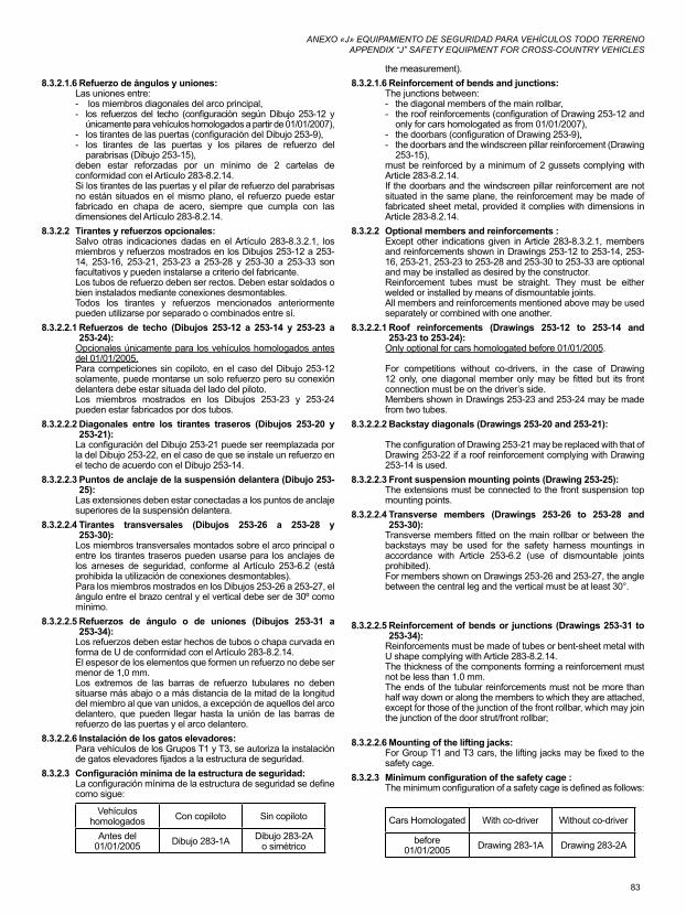
83
ANEXO «J» EQUIPAMIENTO DE SEGURIDAD PARA VEHÍCULOS TODO TERRENOAPPENDIX “J” SAFETY EQUIPMENT FOR CROSS-COUNTRY VEHICLES
8.3.2.1.6 Refuerzo de ángulos y uniones:Las uniones entre:- los miembros diagonales del arco principal,- los refuerzos del techo (configuración según Dibujo 253-12 y
únicamente para vehículos homologados a partir de 01/01/2007),- los tirantes de las puertas (configuración del Dibujo 253-9),- los tirantes de las puertas y los pilares de refuerzo del
parabrisas (Dibujo 253-15),deben estar reforzadas por un mínimo de 2 cartelas de conformidad con el Artículo 283-8.2.14.Si los tirantes de las puertas y el pilar de refuerzo del parabrisas no están situados en el mismo plano, el refuerzo puede estar fabricado en chapa de acero, siempre que cumpla con las dimensiones del Artículo 283-8.2.14.
8.3.2.2 Tirantes y refuerzos opcionales:Salvo otras indicaciones dadas en el Artículo 283-8.3.2.1, los miembros y refuerzos mostrados en los Dibujos 253-12 a 253-14, 253-16, 253-21, 253-23 a 253-28 y 253-30 a 253-33 son facultativos y pueden instalarse a criterio del fabricante.Los tubos de refuerzo deben ser rectos. Deben estar soldados o bien instalados mediante conexiones desmontables.Todos los tirantes y refuerzos mencionados anteriormente pueden utilizarse por separado o combinados entre sí.
8.3.2.2.1 Refuerzos de techo (Dibujos 253-12 a 253-14 y 253-23 a 253-24):
Opcionales únicamente para los vehículos homologados antes del 01/01/2005.Para competiciones sin copiloto, en el caso del Dibujo 253-12 solamente, puede montarse un solo refuerzo pero su conexión delantera debe estar situada del lado del piloto.Los miembros mostrados en los Dibujos 253-23 y 253-24 pueden estar fabricados por dos tubos.
8.3.2.2.2 Diagonales entre los tirantes traseros (Dibujos 253-20 y 253-21):
La configuración del Dibujo 253-21 puede ser reemplazada por la del Dibujo 253-22, en el caso de que se instale un refuerzo en el techo de acuerdo con el Dibujo 253-14.
8.3.2.2.3 Puntos de anclaje de la suspensión delantera (Dibujo 253-25):
Las extensiones deben estar conectadas a los puntos de anclaje superiores de la suspensión delantera.
8.3.2.2.4 Tirantes transversales (Dibujos 253-26 a 253-28 y 253-30):
Los miembros transversales montados sobre el arco principal o entre los tirantes traseros pueden usarse para los anclajes de los arneses de seguridad, conforme al Artículo 253-6.2 (está prohibida la utilización de conexiones desmontables).Para los miembros mostrados en los Dibujos 253-26 a 253-27, el ángulo entre el brazo central y el vertical debe ser de 30º como mínimo.
8.3.2.2.5 Refuerzos de ángulo o de uniones (Dibujos 253-31 a 253-34):
Los refuerzos deben estar hechos de tubos o chapa curvada en forma de U de conformidad con el Artículo 283-8.2.14.El espesor de los elementos que formen un refuerzo no debe ser menor de 1,0 mm.Los extremos de las barras de refuerzo tubulares no deben situarse más abajo o a más distancia de la mitad de la longitud del miembro al que van unidos, a excepción de aquellos del arco delantero, que pueden llegar hasta la unión de las barras de refuerzo de las puertas y el arco delantero.
8.3.2.2.6 Instalación de los gatos elevadores:Para vehículos de los Grupos T1 y T3, se autoriza la instalación de gatos elevadores fijados a la estructura de seguridad.
8.3.2.3 Configuraciónmínimadelaestructuradeseguridad:La configuración mínima de la estructura de seguridad se define como sigue:
Vehículos homologados Con copiloto Sin copiloto
Antes del 01/01/2005 Dibujo 283-1A Dibujo 283-2A
o simétrico
the measurement).8.3.2.1.6 Reinforcement of bends and junctions:
The junctions between:- the diagonal members of the main rollbar,- the roof reinforcements (configuration of Drawing 253-12 and
only for cars homologated as from 01/01/2007),- the doorbars (configuration of Drawing 253-9),- the doorbars and the windscreen pillar reinforcement (Drawing
253-15),must be reinforced by a minimum of 2 gussets complying with Article 283-8.2.14.If the doorbars and the windscreen pillar reinforcement are not situated in the same plane, the reinforcement may be made of fabricated sheet metal, provided it complies with dimensions in Article 283-8.2.14.
8.3.2.2 Optional members and reinforcements :Except other indications given in Article 283-8.3.2.1, members and reinforcements shown in Drawings 253-12 to 253-14, 253-16, 253-21, 253-23 to 253-28 and 253-30 to 253-33 are optional and may be installed as desired by the constructor.Reinforcement tubes must be straight. They must be either welded or installed by means of dismountable joints.All members and reinforcements mentioned above may be used separately or combined with one another.
8.3.2.2.1 Roof reinforcements (Drawings 253-12 to 253-14 and 253-23 to 253-24):
Only optional for cars homologated before 01/01/2005.
For competitions without co-drivers, in the case of Drawing 12 only, one diagonal member only may be fitted but its front connection must be on the driver’s side.Members shown in Drawings 253-23 and 253-24 may be made from two tubes.
8.3.2.2.2 Backstay diagonals (Drawings 253-20 and 253-21):
The configuration of Drawing 253-21 may be replaced with that of Drawing 253-22 if a roof reinforcement complying with Drawing 253-14 is used.
8.3.2.2.3 Front suspension mounting points (Drawing 253-25):The extensions must be connected to the front suspension top mounting points.
8.3.2.2.4 Transverse members (Drawings 253-26 to 253-28 and 253-30):
Transverse members fitted on the main rollbar or between the backstays may be used for the safety harness mountings in accordance with Article 253-6.2 (use of dismountable joints prohibited).For members shown on Drawings 253-26 and 253-27, the angle between the central leg and the vertical must be at least 30°.
8.3.2.2.5 Reinforcement of bends or junctions (Drawings 253-31 to 253-34):
Reinforcements must be made of tubes or bent-sheet metal with U shape complying with Article 283-8.2.14.The thickness of the components forming a reinforcement must not be less than 1.0 mm.The ends of the tubular reinforcements must not be more than half way down or along the members to which they are attached, except for those of the junction of the front rollbar, which may join the junction of the door strut/front rollbar;
8.3.2.2.6 Mounting of the lifting jacks:For Group T1 and T3 cars, the lifting jacks may be fixed to the safety cage.
8.3.2.3 Minimumconfigurationofthesafetycage:The minimum configuration of a safety cage is defined as follows:
Cars Homologated With co-driver Without co-driver
before01/01/2005 Drawing 283-1A Drawing 283-2A
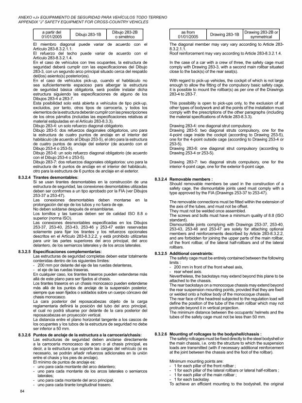
84
ANEXO «J» EQUIPAMIENTO DE SEGURIDAD PARA VEHÍCULOS TODO TERRENOAPPENDIX “J” SAFETY EQUIPMENT FOR CROSS-COUNTRY VEHICLES
a partir del01/01/2005 Dibujo 283-1B Dibujo 283-2B
o simétrico
El miembro diagonal puede variar de acuerdo con el Artículo 283-8.3.2.1.1.El refuerzo del techo puede variar de acuerdo con el Artículo 283-8.3.2.1.4.En el caso de vehículos con tres ocupantes, la estructura de seguridad deberá cumplir con las especificaciones del Dibujo 283-3, con un segundo arco principal situado cerca del respaldo del(los) asiento(s) posterior(es).En el caso de vehículos pick-up, cuando el habitáculo no sea suficientemente espacioso para albergar la estructura de seguridad básica obligatoria, será posible instalar dicha estructura siguiendo las especificaciones de alguno de los Dibujos 283-4 a 283-7.Esta posibilidad solo está abierta a vehículos de tipo pick-up, excluidos, por tanto, otros tipos de carrocería, y todos los elementos de la estructura deberán cumplir con las prescripciones de los otros párrafos (incluidas las especificaciones relativas al material estipuladas en el Artículo 283-8.3.3).Dibujo 283-4: un solo refuerzo diagonal obligatorio.Dibujo 283-5: dos refuerzos diagonales obligatorios, uno para la estructura de cuatro puntos de anclaje en el interior del habitáculo (de acuerdo al Dibujo 253-5), el otro para la estructura de cuatro puntos de anclaje del exterior (de acuerdo con el Dibujo 253-4 o 253-5).Dibujo 283-6: un solo refuerzo diagonal obligatorio (de acuerdo con el Dibujo 253-4 o 253-5).Dibujo 283-7: dos refuerzos diagonales obligatorios: uno para la estructura de 4 puntos de anclaje en el interior del habitáculo, otro para la estructura de 6 puntos de anclaje en el exterior.
8.3.2.4 Tirantes desmontables:Si se usan tirantes desmontables en la construcción de una estructura de seguridad, las conexiones desmontables utilizadas deben ser conformes a un tipo aprobado por la FIA (ver Dibujos 253-37 a 253-47).Las conexiones desmontables deben montarse en la prolongación del eje de los tubos y no fuera de eje.No deben soldarse después de ensamblarse.Los tornillos y las tuercas deben ser de calidad ISO 8.8 o superior (norma ISO).Las conexiones desmontables especificadas en los Dibujos 253-37, 253-40, 253-43, 253-46 y 253-47 están reservadas solamente para fijar los tirantes y los refuerzos opcionales descritos en el Artículo 283-8.3.2.2, y está prohibido utilizarlas para unir las partes superiores del arco principal, del arco delantero, de los semiarcos laterales y de los arcos laterales.
8.3.2.5 Especificacionescomplementarias:Las estructuras de seguridad completas deben estar totalmente contenidas dentro de los siguientes límites:- 200 mm por delante del eje de las ruedas delanteras,- el eje de las ruedas traseras.En cualquier caso, los tirantes traseros pueden extenderse más allá de este plano para ser fijados al chasis.Los tirantes traseros en un chasis monocasco pueden extenderse más allá de los puntos de anclaje de la suspensión posterior, siempre que sean fijados o soldados sobre un cuerpo cóncavo del chasis monocasco.La cara posterior del reposacabezas objeto de la carga reglamentaria definirá la posición del tubo del arco principal, el cual no podrá situarse por delante de la cara posterior del reposacabezas en proyección vertical.La distancia entre el plano horizontal tangente a los cascos de los ocupantes y los tubos de la estructura de seguridad no debe ser inferior a 50 mm.
8.3.2.6 Puntos de anclaje de la estructura a la carrocería/chasis:Las estructuras de seguridad deben anclarse directamente a la carrocería monocasco de acero o al chasis principal, es decir, a la estructura que soporte las cargas del vehículo (si es necesario, se podrán añadir refuerzos adicionales en la unión entre el chasis y los pies de anclaje).El mínimo de puntos de anclaje es:- uno para cada montante del arco delantero;- uno para cada montante de los arcos laterales o semiarcos
laterales;- uno para cada montante del arco principal;- uno para cada tirante longitudinal trasero.
as from01/01/2005 Drawing 283-1B Drawing 283-2B or
symmetrical
The diagonal member may vary vary according to Article 283-8.3.2.1.1.Roof reinforcement may vary according to Article 283-8.3.2.1.4.
In the case of a car with a crew of three, the safety cage must comply with Drawing 283-3, with a second main rollbar situated close to the back(s) of the rear seat(s).
With regard to pick-up vehicles, the cockpit of which is not large enough to allow the fitting of the compulsory basic safety cage, it is possible to mount the rollbar(s) as per one of the Drawings 283-4 to 283-7.
This possibility is open to pick-ups only, to the exclusion of all other types of bodywork and all the points of the installation must comply with the prescriptions of the other paragraphs (including the material specifications of Article 283-8.3.3).
Drawing 283-4: one diagonal strut compulsory.Drawing 283-5: two diagonal struts compulsory, one for the 4-point cage inside the cockpit (according to Drawing 253-5), one for the 4-point outside cage (according to Drawing 253-4 or 253-5).Drawing 283-6: one diagonal strut compulsory (according to Drawing 253-4 or 253-5).
Drawing 283-7: two diagonal struts compulsory, one for the interior 4-point cage, one for the exterior 6-point cage.
8.3.2.4 Removable members :Should removable members be used in the construction of a safety cage, the dismountable joints used must comply with a type approved by the FIA (Drawings 253-37 to 253-47).
The removable connections must be fitted within the extension of the axis of the tubes, and must not be offset.They must not be welded once assembled.The screws and bolts must have a minimum quality of 8.8 (ISO standard).Dismountable joints complying with Drawings 253-37, 253-40, 253-43, 253-46 and 253-47 are solely for attaching optional members and reinforcements described by Article 283-8.3.2.2, and are forbidden for joining the upper parts of the main rollbar, of the front rollbar, of the lateral half-rollbars and of the lateral rollbars.
8.3.2.5 Additional constraints:The safety cage must be entirely contained between the following limits :- 200 mm in front of the front wheel axis,- rear wheel axis.Nevertheless, the backstays may extend beyond this plane to be attached to the chassis.The rear backstays on a monocoque chassis may extend beyond the rear suspension mounting points, provided that they are fixed or welded onto a hollow body of the monocoque chassis.The rear face of the headrest subjected to the regulation load will define the position of the tube of the main rollbar which may not protrude beyond it in vertical projection.The minimum distance between the occupants’ helmets and the tubes of the safety cage must not be less than 50 mm.
8.3.2.6 Mounting of rollcages to the bodyshell/chassis :The safety rollcages must be fixed directly to the steel bodyshell or the main chassis, i.e. onto the structure to which the suspension loads are transmitted (with if necessary additional reinforcement at the joint between the chassis and the foot of the rollbar).
Minimum mounting points are:- 1 for each pillar of the front rollbar ;- 1 for each pillar of the lateral rollbars or lateral half-rollbars ;- 1 for each pillar of the main rollbar ;- 1 for each backstay.To achieve an efficient mounting to the bodyshell, the original
85
ANEXO «J» EQUIPAMIENTO DE SEGURIDAD PARA VEHÍCULOS TODO TERRENOAPPENDIX “J” SAFETY EQUIPMENT FOR CROSS-COUNTRY VEHICLES
Para conseguir un montaje óptimo en la carrocería, el guarnecido original puede ser modificado junto a la estructura de seguridad o sus puntos de anclaje, recortándolo o modificándolo localmente.Sin embargo, esta modificación no permite la eliminación completa de partes de la tapicería o guarnecido.Si es necesario, la caja de fusibles podrá ser trasladada para permitir el montaje de la estructura de seguridad.Puntos de anclaje del arco delantero, arco principal, arcos laterales o semiarcos laterales:Cada punto de anclaje debe incluir una placa de refuerzo de un espesor de, al menos, 3 mm.Cada pie de anclaje debe estar fijado por, al menos, 3 tornillos en una placa de refuerzo de acero, soldada a la carrocería, que tenga al menos 3 mm de espesor y una superficie mínima de 120cm2.Para vehículos homologados a partir del 01/01/2007, el área de 120 cm2 debe ser la superficie de contacto entre la placa de refuerzo y la carrocería.Se muestran ejemplos en los Dibujos 253-50 a 253-56.Para el Dibujo 253-52, la placa de refuerzo no requiere necesariamente estar soldada a la carrocería.En el caso del Dibujo 253-54, los laterales del punto de anclaje pueden cerrarse con una placa soldada.Los tornillos deben ser, al menos, de diámetro M8 y de calidad ISO 8.8 o superior (norma ISO).Las tuercas serán autoblocantes o dotadas de arandelas de bloqueo.El ángulo entre 2 tornillos (medido con respecto al eje central del tubo al nivel del pie de anclaje, cf. Dibujo 253-50) no debe ser inferior a 60 grados.Puntos de anclaje de los tirantes traseros:Cada tirante longitudinal trasero deberá estar fijado con al menos 2 tornillos M8 y placas de refuerzo cuya superficie mínima sea de 60 cm2 (Dibujo 253-57), o bien fijado con un solo tornillo a doble cizalladura (Dibujo 253-58), siempre que este sea de la sección y resistencia adecuadas y a condición de que se suelde un manguito al tirante. Sus puntos de anclaje deben estar reforzados por placas.Estas exigencias son las mínimas.Como complemento, pueden utilizarse fijaciones suplementarias, las placas de apoyo de los pies de los arcos pueden soldarse a las placas de refuerzo, la estructura de seguridad (tal como ha sido definida en el Artículo 283-8.3.1) puede soldarse a la carrocería/chasis.Caso especial:Los miembros diagonales anclados a la carrocería (ver Dibujo 253-6) deben llevar las placas de refuerzo mencionadas anteriormente.Para carrocerías/chasis que no sean de acero, cualquier soldadura entre la estructura de seguridad y la carrocería/chasis está prohibida, solo se permite el pegado de la placa de refuerzo en la carrocería/chasis.En el caso de los vehículos con chasis tubulares o semitubulares (Grupo T1), la estructura de seguridad debe soldarse al chasis o formar parte integrante del chasis.Los puntos de fijación de los arcos delanteros, laterales, semilaterales y principales deben situarse, como mínimo, en el nivel del suelo del habitáculo.Al menos, un tubo de la misma sección y calidad debe prolongar cada pie del arco hacia abajo.Se recomienda una diagonal suplementaria, así como un tubo horizontal al nivel del suelo.
8.3.3 EspecificacionesdelosmaterialesSolo se autorizan tubos de sección circular.Especificaciones de los tubos utilizados:
MaterialResistencia mínima a la
tracción
Dimensionesmínimas
(mm)Utilización
interior trim may be modified around the safety cages and their mountings by cutting it away or by distorting it.However, this modification does not permit the removal of complete parts of upholstery or trim.Where necessary, the fuse box may be moved to enable a rollcage to be fitted.Mounting points of the front, main, lateral rollbars or lateral half-rollbars:Each mounting point must include a reinforcement plate at least 3 mm thick.Each mounting foot must be attached by at least three bolts on a steel reinforcement plate at least 3 mm thick and of at least 120cm2 area which is welded to the bodyshell.For cars homologated as from 01/01/2007, the area of 120 cm2 must be the contact surface between the reinforcement plate and the bodyshell.
Examples according to Drawings 253-50 to 253-56.For Drawing 253-52, the reinforcement plate need not necessarily be welded to the bodyshell.In the case of Drawing 253-54, the sides of the mounting point may be closed with a welded plate.Fixing bolts must have a minimum diameter of M8 and a minimum quality of 8.8 (ISO standard).Fasteners must be self-locking or fitted with lock washers.
The angle between 2 bolts (measured from the tube axis at the level of the mounting foot, cf. Drawing 253-50) must not be less than 60 degrees.Mounting points of the backstays:Each backstay must be secured by a minimum of 2 M8 bolts (2008) with mounting feet of at least 60 cm2 area (Drawing 253-57), or secured by a single bolt in double shear (Drawing 253-58), provided it is of adequate section and strength and provided that a bush is welded into the backstay.Their mountings must be reinforced by plates.
These are minimum requirements.In addition, more fasteners may be used, the support plates of the mounting feet may be welded to reinforcement plates, the safety cage (as defined by Article 283-8.3.1) may be welded to the bodyshell/chassis.
Special case:Diagonal members fixed to the bodyshell (see Drawing 253-6) must have reinforcement plates as defined above.
For non-steel bodyshells/chassis, any weld between the cage and the bodyshell/chassis is prohibited, only the bonding of the reinforcement plate on the bodyshell/chassis is permitted.Rollcages equipping vehicles with a tubular or semi-tubular space frame (Group T1) must be welded to the chassis or be an integral part of it.The mounting points of the front, lateral, semi-lateral and main rollbars must be situated at least at the level of the cockpit floor.
At least one tube of the same section and quality must extend each foot of the rollbar downwards.Another diagonal is recommended, as well as a horizontal tube at floor level.
8.3.3 MaterialspecificationsOnly tubes with a circular section are authorised.Specifications of the tubes used:
MaterialMinimum
tensilestrength
MinimumDimensiones
(mm)Use
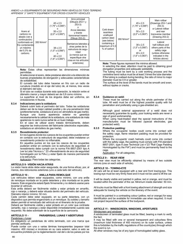
86
ANEXO «J» EQUIPAMIENTO DE SEGURIDAD PARA VEHÍCULOS TODO TERRENOAPPENDIX “J” SAFETY EQUIPMENT FOR CROSS-COUNTRY VEHICLES
Cold drawn seamless unalloyed
carbon steel (see below) containing a
maximum of 0,3 % of carbon
350 N/mm²
45 x 2,5(1,75" x 0,095")
or50 x 2,0
(2,0" x 0,083")
Main rollbar(Drawings 253-1 and
253-3)or Lateral rollbar
and rear transverse member
(Drawing 253-2)
38 x 2,5(1,5" x 0,095")
or40 x 2,0
(1,6" x 0,083")
Lateral half-rollbars and
others parts of the safety cage
(unless otherwise indicated in the Articles above)
Note: These figures represent the minima allowed.In selecting the steel, attention must be paid to obtaining good elongation properties and adequate weldability.The tubing must be bent by a cold working process and the centreline bend radius must be at least 3 times the tube diameter.If the tubing is ovalised during bending, the ratio of minor to major diameter must be 0.9 or greater.The surface at the level of the bends must be smooth and even, without ripples or cracks.
8.3.4 Guidance on weld:These must be carried out along the whole perimeter of the tube. All weld must be of the highest possible quality with full penetration and preferably using a gas-shielded arc.
Although good external appearance of a weld does not necessarily guarantee its quality, poor looking welds are never a sign of good workmanship.When using heat-treated steel the special instructions of the manufacturers must be followed (special electrodes, gas protected weld).
8.3.5 Protective padding:Where the occupants’ bodies could come into contact with the safety cage, flame retardant padding must be provided for protection.Where the occupants’ crash helmets could come into contact with the safety cage, the padding must comply with FIA standard 8857-2001, type A (see Technical List n°23 "Roll Cage Padding Homologated by the FIA") and must be permanently fixed to the cage.Application: For all categories.
ARTICLE 9 - REAR VIEWThe rear view must be efficiently obtained by means of two outside mirrors (one on each side of vehicle).
ARTICLE 10 - TOWING-EYEAll cars will be at least equipped with a rear and front towing-eye. This towing-eye must be very firmly fixed and it must not be used to lift the car.
It will be clearly visible and painted in yellow, red or orange, and must be located within the perimeter of the car. Minimum inside diameter: 50 mm.
All trucks must be fitted with a front towing attachment of strength and size adequate for towing the vehicle on the itinerary of the event.
It must be painted in a contrasting colour (yellow, red or orange) for easy identification and be available for immediate use when required. It must not project beyond the surface of the bodywork.
ARTICLE 11 - WINDSCREEN, WINDOWS, APERTURESWindscreen and windows:A windscreen of laminated glass must be fitted, bearing a mark to verify the fact.It may be fitted with one or several transparent and colourless films (maximum total thickness of 400 microns) on its outer surface, unless this is forbidden by the traffic regulations of the country(ies) through which the event is run.All other windows may be of any type of homologated safety glass.
Acero al carbono no
aleado (ver a continuación)
conformado en frío conteniendo
un máximo del 0,3% de
carbono.
350 N/mm²
45 x 2,5(1,75" x 0,095")
o50 x 2,0
(2,0" x 0,083")
Arco principal(Dibujos 253-1 y
253-3)o
Arcos lateralesy tirante
transversal trasero(Dibujo 253-2);
38 x 2,5(1,5" x 0,095")
o40 x 2,0
(1,6" x 0,083")
Semiarcos laterales y otras partes de la
estructura de segu-ridad
(a menos que se especifique otra
cosa en los artículos anteriores)
Nota: Estas cifras representan las dimensiones mínimas permitidas.Al seleccionar el acero, debe prestarse atención a la obtención de buenas propiedades de elongación y adecuadas características de soldabilidad.El curvado del tubo debe hacerse en frío con un radio de curvatura (medido en el eje del tubo) de, al menos, tres veces el diámetro del tubo.Si el tubo se ovaliza durante esta operación, la relación entre el diámetro menor y mayor deberá ser de 0,9 como mínimo.La superficie al nivel de los ángulos debe ser uniforme, sin ondulaciones ni fisuras.
8.3.4 Indicaciones para la soldadura:Deberá cubrir todo el perímetro del tubo. Todas las soldaduras deben ser de la mejor calidad posible y de una penetración total (preferentemente, soldadura al arco en atmósfera de gas inerte).Aunque una buena apariencia exterior no garantiza necesariamente la calidad de la soldadura, una soldadura de mala apariencia no será nunca señal de un buen trabajo.En el caso de utilizar acero tratado térmicamente, deben seguirse las instrucciones del fabricante (electrodos especiales, soldadura en atmósfera de gas inerte).
8.3.5 Revestimiento protector:En los lugares donde los cuerpos de los ocupantes puedan entrar en contacto con la estructura de seguridad, debe instalarse un revestimiento protector no inflamable.En aquellos puntos en los que los cascos de los ocupantes pudieran entrar en contacto con la estructura de seguridad, el revestimiento debe cumplir con la norma FIA 8857-2001 tipo A (ver la Lista Técnica n.° 23 «Revestimiento de arco de seguridad homologado por la FIA») y estar fijado de manera permanente a la estructura.Aplicación: Para todas las categorías.
ARTÍCULO 9 - VISIÓN HACIA ATRÁSLa visión hacia atrás debe estar asegurada, de una forma eficaz, por, al menos, dos retrovisores exteriores (uno a cada lado del vehículo).
ARTÍCULO 10 - ANILLA PARA REMOLQUELos vehículos deben estar equipados, como mínimo, con una anilla de remolque montada en la parte delantera y otra montada en la parte trasera. Este enganche estará fijado firmemente y no deberá usarse para levantar el vehículo.Esta anilla deberá ser fácilmente visible y estar pintada en amarillo, rojo o naranja, y deberá estar situada dentro del perímetro del vehículo. Diámetro interior mínimo: 50 mm.Cada camión debe estar equipado, en su parte delantera, con un dispositivo que permita engancharlo a un remolque. Su solidez y tamaño deben permitir el remolcado del vehículo en el itinerario de la prueba.Deberá ser fácilmente visible y estar pintado en un color que contraste (amarillo, rojo o naranja) y estar disponible inmediatamente cuando sea requerido. No debe sobresalir de la superficie de la carrocería.
ARTÍCULO 11 - PARABRISAS, LUNAS Y ABERTURASParabrisas y lunas:Es obligatorio un parabrisas de vidrio laminado, con una marca que permita verificarlo. Puede contar con una o varias láminas transparentes (espesor total máximo: 400 micras) e incoloras en su cara exterior, salvo si esto se encuentra prohibido por la reglamentación vial del o de los países por los
87
ANEXO «J» EQUIPAMIENTO DE SEGURIDAD PARA VEHÍCULOS TODO TERRENOAPPENDIX “J” SAFETY EQUIPMENT FOR CROSS-COUNTRY VEHICLES
A sun strip for the windscreen is authorised (see Appendix L), on condition that it allows the occupants to see the road signs (traffic lights, traffic signs…).In the event of absence of a windscreen at the start of a leg, the wearing of a full face helmet with a visor or of motocross type goggles, or of an open face helmet with motocross type goggles shall be compulsory for all members of the crew, otherwise the vehicle shall not be admitted to the start of the leg.During legs, crews must always have motocross type goggles in the cockpit, to be used in case of windscreen breakage.
If, after an accident, the deformation of the bodywork will not allow the replacement of the windscreen by a windscreen made from laminated glass, it may be replaced by a windscreen made from polycarbonate with a minimum thickness of 5 mm.If the windscreen is glued, it must be possible, from inside the cockpit, to break the windows of the front doors or to remove them without using tools.The rear and side windows, if transparent, must be made from a homologated material or from polycarbonate with a minimum thickness of 3 mm.The use of transparent and colourless anti-shatter films on the interior face of the side windows, the rear window, the glass sunroof and the outside rear-view mirrors is mandatory (only for parts made from glass). The thickness of these films must not be greater than 100 microns and they must be fitted with an indicator allowing the control of their presence.The use of tinted glass is permitted in side and rear windows. In such cases it must be possible for a person situated 5 m from the car to see the occupants as well as the contents of the car.
Nets:All vehicles of which the front doors are fitted with wind-down windows or glass windows must be equipped with protection nets affixed to these doors using a quick release system situated on the lower part.
The use of "clip" fixings is recommended. The fixings of the net on the upper part must not be removable without the use of tools.These nets must have the following characteristics :
- Minimum width of the strips : 19 mm- Minimum size of the meshes : 25 x 25 mm.- Maximum size of the meshes : 60 x 60 mm.
and, viewed from the side, must reach from the centre of the steering wheel to the rearmost point of the seat on the side concerned.
ARTICLE 12 - SAFETY FIXING DEVICES FOR WINDSCREENSuch devices may be used freely.
ARTICLE 13 - GENERAL CIRCUIT BREAKERThe anti-theft device of the original main ignition switch ("Neiman") must be removed.The general circuit breaker must cut all electrical circuits, battery, alternator or dynamo, lights, hooters, ignition, electrical controls, etc.) and must also stop the engine.For Diesel engines having no electronically controlled injectors, the circuit breaker must be coupled with a device cutting off the intake into the engine.It must be a spark-proof model, and will be accessible from inside the car by the driver and the co-driver(s), seated and secured by their safety belts, and from outside the car.Group T1, T3 and T2 cars must be equipped with two external switches, one on either side of the bottom of the windscreen pillars.
They will be marked by a red spark in a white-edged blue triangle with a base of at least 12 cm.Trucks must be fitted with a circuit breaker and / or a choker device which shuts down the engine and disconnects the batteries from all electrical circuitry (except any automatic fire extinguisher system).
This switch must be painted yellow and identified by a red spark on a white edged, blue triangle.A prominent notice not less than 20 cm in width should be affixed to indicate the location of the switch.The circuit breaker and the choker device must be placed on the outside, in the middle of the front face of the cab, beneath the windscreen.
The circuit breaker must be easily accessible at all times, even if the vehicle is lying on its side or roof.In addition, an engine shut-down switch must be fitted in the cab, with its
que pasa la prueba.Todas las otras lunas pueden ser de cualquier tipo de cristal de seguridad homologado.Se permite el uso de una banda parasol en el parabrisas (ver Anexo L), a condición de que dicha banda permita a los ocupantes ver las señales de tráfico (semáforos, señales...).En caso de ausencia de parabrisas al inicio de una etapa, es obligatorio que todos los miembros del equipo utilicen casco integral con visera o gafas de tipo motocross, o bien un casco abierto con gafas de tipo motocross; en caso contrario, el vehículo no será admitido en la salida.
Durante el desarrollo de las etapas, los equipos deben tener permanentemente, en el habitáculo, gafas de tipo motocross que serán utilizadas si se rompe el parabrisas.Si, después de un accidente, la deformación de la carrocería no permitiera la sustitución del parabrisas por un parabrisas de vidrio laminado, podrá sustituirse por un parabrisas de policarbonato con un espesor mínimo de 5 mm.Si el parabrisas está pegado, debe ser posible romper o desmontar las ventanillas delanteras desde el interior del habitáculo. El desmontaje debe poder hacerse sin utilizar herramientas.Las ventanillas traseras y laterales, si son transparentes, deben estar hechas de un material homologado o de policarbonato con un espesor mínimo de 3 mm.Es obligatorio el uso de láminas de seguridad antideflagrantes, transparentes e incoloras en la cara interior de las ventanillas laterales, de la luna trasera, del techo solar y de los espejos retrovisores exteriores (solo para las partes hechas en cristal). El espesor de dichas láminas no puede ser superior a 100 micras y deben tener una marca para verificar su instalación.El uso de láminas tintadas se autoriza en las ventanillas laterales y en la luna trasera. En ese caso, deben permitir a una persona situada a 5m del vehículo ver a los ocupantes, así como el contenido del vehículo.Redes:Todos los vehículos en los que las puertas delanteras estén equipadas con ventanillas descendentes o ventanillas de cristal, deben estar equipados con redes de protección fijadas a esas puertas y con un sistema de desconexión rápida en su parte inferior.El uso de fijaciones tipo «clip» está recomendado. Las fijaciones de la red a la parte superior no deben ser desmontables sin el uso de herramientas.Estas redes deben tener las siguientes características:
- Anchura mínima de las bandas: 19 mm.- Tamaño mínimo de las aberturas: 25 x 25 mm.- Tamaño máximo de las aberturas: 60 x 60 mm.
Y deben extenderse, vistas de lado, desde el centro del volante hasta el punto más alejado hacia atrás del asiento del lado correspondiente.
ARTÍCULO 12 - FIJACIONES DE SEGURIDAD DEL PARABRISAS
Estas fijaciones pueden usarse libremente.
ARTÍCULO 13 - CORTACORRIENTEDebe suprimirse el dispositivo antirrobo original (de tipo «Neiman») del interruptor de encendido principal.El cortacorriente general debe cortar todos los circuitos eléctricos (batería, alternador o dinamo, luces, claxon, encendido, controles eléctricos, etc.), y debe parar el motor.Para motores diésel que no tengan inyectores controlados electrónicamente, el cortacorriente debe estar conectado a un dispositivo que interrumpa la admisión del motor.Debe ser un modelo antideflagrante y será accesible desde el interior del vehículo por el conductor y el(los) copiloto(s) sentados y con sus cinturones abrochados, y desde el exterior del vehículo.Los vehículos de los Grupos T1, T3 y T2 deben estar equipados con dos interruptores externos, uno a cada lado de la base de los montantes del parabrisas.Estarán claramente marcados mediante un rayo rojo en un triángulo azul con borde blanco y una base de, al menos, 12 cm.Los camiones deben estar equipados con un cortacorriente y/o un dispositivo de corte que apague el motor y desconecte las baterías de todos los circuitos eléctricos (a excepción de cualquier sistema automático de extinción).Este interruptor debe estar pintado de amarillo e identificado por un rayo rojo, dentro de un triángulo azul con borde blanco.Su posición debe estar señalada por una indicación visible de, al menos, 20cm de anchura.El cortacorriente y el dispositivo de corte deben estar situados en el exterior, en la mitad de la cara delantera de la cabina, debajo del parabrisas.
88
ANEXO «J» EQUIPAMIENTO DE SEGURIDAD PARA VEHÍCULOS TODO TERRENOAPPENDIX “J” SAFETY EQUIPMENT FOR CROSS-COUNTRY VEHICLES
on-off positions clearly marked.It must be operable by the driver and the co-driver(s) when normally seated and secured by their safety belts. The switch must also isolate any electric fuel pumps.
Note: In the case of vehicles which use a mechanical engine shut-down system, a shut-down device may be fitted on the outside, separate to the electrical circuit breaker. However, the device must be fitted close to the circuit breaker, be clearly marked and have clear operating instructions (e.g. pull knob to stop engine).
ARTICLE 14 - FIA APPROVED SAFETY FUEL TANKSWhenever a competitor uses a safety fuel tank, it must come from a manufacturer approved by the FIA.To this end, on each tank delivered, the name of the manufacturer, the exact specifications according to which this tank has been manufactured, the homologation number, the date of the end of validity and the series number, shall be marked.The marking process must be indelible and must have been approved beforehand by the FIA according to the prevailing standard.
14.1 Ageing of tanksThe ageing of safety tanks entails a considerable reduction in the strength characteristics after approximately five years.No bladder shall be used more than 5 years after the date of manufacture, unless inspected and recertified by the manufacturer for a period of up to another two years.A leak-proof cover, made from non-flammable material, easily accessible and removable only with the use of tools, must be installed in the protection for FT3 1999, FT3.5 or FT5 tanks, in order to allow the checking of the validity expiry date.
14.2 Installation of tanksThe tank may be replaced by a safety tank homologated by the FIA (FT3 1999, FT3.5 or FT5 specification), or by another tank homologated by the manufacturer of the car. In this case a panel may be used to close off the opening left by the removal of the original tank. The number of tanks is free.
It is also possible to combine the various homologated tanks (including the standard tank) and FT3 1999, FT3.5 or FT5 tanks.
Any tank which is not homologated with the vehicle by a manufacturer recognized by the FIA must be an FT3 1999, FT3.5 or FT5 tank.Collecting tanks with a capacity of less than 1 litre are of free construction, but their number is limited by that of the main tanks equipping the vehicle.The original tank may be conserved in its original position.An increased capacity FT3 1999, FT3.5 or FT5 tank may be fitted in the position of the original tank.For Group T2 cars in respect of which the manufacturer has provided for a closed compartment for luggage (front or rear luggage space) which is an integral part of the bodywork, this compartment must be used to house the additional tank.Holes must be provided for in the floor of the boot in order to allow the outflow of the fuel in the event of a leak.For cars in respect of which the manufacturer has not provided for a specific luggage compartment, as an integral part of the bodywork, the additional tank may be situated inside the cockpit to the rear of the rearmost seat.
In all cases, the tank including the filling pipes, must be totally insulated by means of flameproof and liquid-tight bulkheads or casing, preventing the infiltration of fuel into the cockpit or contact with the exhaust pipes.
Should the tank be installed in the luggage compartment, and when the rear seats are removed, the cockpit must be separated from the tank by a fire-resistant, flameproof and liquid-tight bulkhead or casing.In the case of a two-volume car, it will be possible to use a non-structural, non-flammable bulkhead made from transparent plastic between the cockpit and the location of the tank.Tanks must be efficiently protected and very firmly attached to the bodyshell or the chassis of the car.
El cortacorriente general debe ser fácilmente accesible en cualquier momento, incluso si el vehículo está volcado de lado o sobre el techo.Además, un interruptor de paro del motor debe situarse en la cabina, con sus posiciones de encendido-apagado («on-off») claramente marcadas.Debe poder ser accionado por el conductor y el(los) copiloto(s) sentados y atados por sus cinturones. El interruptor debe, asimismo, aislar todas las bombas eléctricas de combustible.Nota: En vehículos que usen un interruptor de motor mecánico, un dispositivo interruptor puede montarse en el exterior, separado del cortacorriente eléctrico. No obstante, este dispositivo debe montarse junto al cortacorriente, estar claramente identificado y tener instrucciones de operación claras (por ejemplo, tirar de la palanca para detener el motor).
ARTÍCULO 14 - DEPÓSITOS DE SEGURIDAD APROBADOS POR LA FIA
En el caso de que un concursante utilice un depósito de combustible de seguridad, este deberá provenir de un fabricante aprobado por la FIA.Con este fin, sobre cada depósito suministrado deberá marcarse el nombre del fabricante, las especificaciones exactas según las cuales se ha fabricado ese depósito, el número de homologación, la fecha de caducidad y el número de serie.El proceso de marcaje debe ser indeleble y debe ser aprobado con antelación por la FIA de acuerdo a la norma existente.14.1 Envejecimiento de los depósitos
El envejecimiento de los depósitos flexibles implica una considerable reducción de sus propiedades físicas después de 5años aproximadamente.No debe utilizarse ningún depósito más de 5 años después de su fecha de fabricación, excepto si es inspeccionado y revalidado por el fabricante durante un período de hasta otros dos años.Una tapa estanca, hecha de un material no inflamable, de fácil acceso y desmontable únicamente con herramientas, debe estar instalada en la protección de los depósitos de seguridad FT3 1999, FT3.5 o FT5 para permitir comprobar la fecha límite de validez.
14.2 Instalación de los depósitosEl depósito puede reemplazarse por un depósito de seguridad homologado por la FIA (especificaciones FT3 1999, FT3.5 o FT5), o por otro depósito homologado por el fabricante del vehículo. En este caso, podrá utilizarse un panel para cerrar la abertura dejada por el depósito retirado. El número de depósitos es libre.También es posible combinar varios depósitos homologados (incluido el depósito de serie) y depósitos FT3 1999, FT3.5 o FT5.Todo depósito que no esté homologado con el vehículo por un fabricante reconocido por la FIA, debe ser un depósito FT3 1999, FT3.5 o FT5.Los depósitos colectores de una capacidad inferior a 1 litro son de construcción libre. Su número está limitado a la cantidad de depósitos principales que equipan el vehículo.El depósito de origen podrá conservarse en su posición original.Un depósito FT3 1999, FT3.5 o FT5, de mayor capacidad puede instalarse en la posición del depósito de origen.Para los vehículos del Grupo T2 en los que el constructor ha previsto un compartimento cerrado para el equipaje (maletero delantero o trasero) que es parte integrante de la carrocería, este compartimento podrá utilizarse para situar un depósito adicional.Deberán preverse orificios en el fondo del maletero para permitir la evacuación del combustible en caso de fuga.Para los vehículos en los que el constructor no ha previsto un compartimento cerrado para el equipaje como parte integrante de la carrocería, el depósito adicional podrá situarse dentro del habitáculo, en la parte posterior al asiento más retrasado.
En todos los casos, el depósito, incluida la canalización de llenado, debe estar totalmente aislado por medio de paneles o carcasas ignífugos y estancos, de modo que se prevenga la introducción de combustible en el habitáculo o el contacto con los conductos del escape.Si el depósito estuviera instalado en el maletero y los asientos hubieran sido retirados, un panel resistente al fuego y estanco deberá separar el habitáculo del depósito.En el caso de un vehículo de dos volúmenes, será posible utilizar un panel o carcasa, no estructural, ignífugo, hecho de plástico transparente, situado entre el habitáculo y la ubicación
89
ANEXO «J» EQUIPAMIENTO DE SEGURIDAD PARA VEHÍCULOS TODO TERRENOAPPENDIX “J” SAFETY EQUIPMENT FOR CROSS-COUNTRY VEHICLES
del depósito.Los depósitos deben estar eficazmente protegidos y muy firmemente anclados a la carrocería o al chasis del vehículo.Se recomienda la utilización de espuma de seguridad en los depósitos FT3 1999, FT3.5 o FT5.La posición y el tamaño del orificio de llenado, así como del tapón de cierre, pueden cambiarse a condición de que la nueva instalación no sobresalga de la carrocería y presente todas las garantías contra una fuga de combustible hacia los compartimentos interiores del vehículo.Estos orificios pueden situarse en la ubicación de las ventanillas traseras o laterales.El orificio de llenado debe estar siempre situado fuera del habitáculo sobre un elemento metálico.Si el orificio de llenado se encuentra en el interior de la carrocería, deberá estar rodeado por un receptáculo que evacue al exterior.El respiradero deberá salir por el techo del vehículo o bien describir un bucle tan alto como sea posible, por el interior del habitáculo, para salir por debajo del vehículo, en el lado opuesto a su conexión con el depósito. Estos respiraderos deberán estar equipados con válvulas autoobturantes.Para los vehículos pick-up en T1 o T2, cuyo habitáculo esté totalmente separado de la plataforma posterior (cabina metálica totalmente cerrada), el depósito deberá ser un depósito FT3 1999, FT3.5 o FT5, y la plataforma deberá modificarse con el fin de permitir la evacuación del combustible en el caso de una fuga.
14.3 Depósitos de combustible con cuellos de llenadoTodos los vehículos equipados con un depósito de combustible con un cuello de llenado que pase por el habitáculo, deben estar equipados con una válvula de no retorno homologada por la FIA. Esta válvula, del tipo «una o dos compuertas», debe instalarse en el cuello de llenado por el lado del depósito. El cuello de llenado se define como el elemento usado para conducir el combustible desde el orificio de llenado del vehículo hasta el interior del depósito.
14.4 RepostajeCon antelación a un procedimiento de reportaje, es necesario instalar una toma a tierra común al vehículo y al dispositivo de reportaje.
14.5 Ventilación de depósitosEl depósito debe estar equipado con una ventilación conforme al Artículo 283.14.2, salvo que se conserve el depósito, el circuito de alimentación de combustible y la ventilación de serie.
ARTÍCULO 15 - PROTECCIÓN CONTRA INCENDIOSDebe colocarse una mampara de protección eficaz entre el motor y todos los elementos mecánicos por una parte, y los asientos de los ocupantes por otra, con el fin de evitar el paso directo de las llamas en caso de incendio.
ARTÍCULO 16 - EQUIPO DE ILUMINACIÓNEl equipamiento de iluminación debe cumplir con la Convención Internacional sobre Tráfico, en todos sus puntos. Cada vehículo deberá estar equipado, como mínimo, con:
- 2 faros (que combinen luces de cruce y de carretera).- 2 pilotos delanteros- 2 pilotos traseros e iluminación para la placa de matrícula- 2 luces de freno- 2 intermitentes en la parte anterior y posterior- luces de avería
Se podrán montar dos faros adicionales, siempre y cuando no estén situados a más de 250 mm por encima de la base del parabrisas.Pueden situarse dentro de los soportes de los retrovisores exteriores.Cada luz de freno tendrá una superficie mínima de 50 cm2. Los dos faros y las luces adicionales deben estar situados por delante del eje de las ruedas delanteras, a una altura máxima correspondiente a la unión del capó con la parte inferior del parabrisas (máximo de ocho lámparas).Todos los faros situados hacia el frente, de más de 32 cm2 de superficie, deben estar adecuadamente protegidos y seguros en caso de rotura del cristal, por una rejilla o un panel traslúcido adicional.Además todos los vehículos estarán equipados con dos luces rojas traseras de niebla adicionales, situadas al lado de dos luces adicionales de freno.Cada una de estas luces debe estar aprobada conforme a la norma de circulación ECE R38 (o una norma de otro país que sea, como mínimo, equivalente a esta) o bien contar con la aprobación de la FIA (Lista Técnica n.º 19).
The use of safety foam in FT3 1999, FT3.5 or FT5 tanks is recommended.The location and dimension of the filler hole and cap may be changed on condition that the new installation does not protrude beyond the bodywork and gives every guarantee against a possible leakage of fuel into one of the inner compartments of the car.
These holes may be situated in the location of the rear or side windows.The filler hole and the air vent must always be situated outside the cockpit on a metal part.If there is a filler hole inside the bodywork, it must be surrounded by a receptacle with outflow to the outside.
The air vent must either come out on the roof of the vehicle or make a loop as high as possible inside the vehicle and come out under the vehicle on the opposite side to its connection to the tank. These air vents must be fitted with self-sealing valves.For pick-up cars in T1 or T2, the cockpit of which is totally separated from the rear platform (completely closed metal cabin), the tank must be an FT3 1999, FT3.5 or FT5 type tank and the platform must be modified in order to allow the outflow of the fuel in the event of a leak.
14.3 FueltankswithfillernecksAll cars fitted with a fuel tank with a filler neck passing through the cockpit must be equipped with a non-return valve homologated by the FIA.This valve, of the type "with one or two flaps", must be installed in the filler neck on the tank side.
The filler neck is defined as being the means used to connect the fuel filler hole of the vehicle to the fuel tank itself.
14.4 RefuellingPrior to any refuelling operation, it is necessary to establish earthing common to the vehicle and to the refuelling device.
14.5 Tank ventilationThe tank must be equipped with ventilation complying with Article 283-14.2, unless the series production tank, fuel feed circuit and ventilation are retained.
ARTICLE 15 PROTECTION AGAINST FIREAn efficient protective screen must be placed between the engine and all the mechanical parts on the one hand, and the occupant’s seats on the other hand, in order to prevent the direct passage of flames in case of fire.
ARTICLE 16 - LIGHTING EQUIPMENTThe lighting equipment must comply on all points with the International Convention on Road Traffic. Each vehicle must be fitted with at least:
- 2 headlights (combined passing lights/headlights)- 2 front lamps- 2 rear lamps and number plate lighting- 2 stop lights- 2 flashing indicators at the front and at the rear- Distress lights.
Two additional headlights may be fitted, provided that they are not situated more than 250 mm above the base of the windscreen.They may be housed inside the supports of the external rear view mirrors.Each ‘stop’ light will have a minimum surface of 50 cm2. The two headlamps and the additional lamps must be located in front of the axis of the front wheels, at a maximum height corresponding to that of the line of the bonnet/bottom of the windscreen (8 lamps maximum).All forward facing lamps of more than 32 cm2 surface area must be adequately protected and secured in case of glass breakage, by a grille or additional translucent panel.Each vehicle must also be equipped with two additionnal red rear fog lamps, twinned or placed side by side with two additional "stop" lights.
Each of these lamps must be approved according to the ECE R38 road standard (or an equivalent or stricter standard from another country), or approved by the FIA (Technical List n°19).
They will be situated at a minimum height of 1.25 m from the ground, visible from the rear and attached to the outside of the vehicle. They must be fixed to both rear sides of the vehicle or, for pick-up type vehicles, to
90
ANEXO «J» EQUIPAMIENTO DE SEGURIDAD PARA VEHÍCULOS TODO TERRENOAPPENDIX “J” SAFETY EQUIPMENT FOR CROSS-COUNTRY VEHICLES
Estarán situadas, como mínimo, a 1,25 m del suelo, y deberán ser visibles desde atrás y estar fijadas al exterior del vehículo. Deberán fijarse a los dos extremos traseros del vehículo o, para los vehículos de tipo pick-up, en los ángulos superiores de la parte trasera de la cabina.Estas luces deben estar permanentemente conectadas durante la realización del sector selectivo, bajo las instrucciones del director de carrera.Todo el equipo de iluminación debe mantenerse en perfecto orden de funcionamiento durante toda la prueba.Un equipo podrá no ser autorizado a tomar la salida de una etapa hasta que haya reparado la instalación eléctrica si se ha comprobado que esta no funciona correctamente.
ARTÍCULO 17 - DISPOSITIVO DE AVISO SONOROTodo vehículo estará equipado con un dispositivo de aviso sonoro, en orden de marcha durante la prueba.
ARTÍCULO 18 - RUEDAS DE REPUESTOCada vehículo incluirá, al menos, dos ruedas de repuesto, idénticas a las que el vehículo tiene instaladas, y que deben estar firmemente fijadas durante toda la prueba.
ARTÍCULO 19 - FALDILLAS GUARDABARROSLas faldillas guardabarros transversales se aceptan con las siguientes condiciones:
- Deben estar hechos de un material flexible.- Deben cubrir, como mínimo, la anchura de cada rueda pero al menos
un tercio de la anchura del vehículo (ver Dibujo 252-6) debe quedar libre por detrás de las ruedas delanteras y traseras.
- Deberá haber una separación de, al menos, 20 cm entre la faldilla derecha y la faldilla izquierda, por delante de las ruedas traseras.
- La parte inferior de las faldillas guardabarros debe estar a no más de 10 cm del suelo cuando el vehículo se encuentra detenido, sin nadie a bordo.
- En proyección vertical, estas faldillas guardabarros no deben sobrepasar la carrocería.
Estas faldillas guardabarros son obligatorias en la parte posterior de las ruedas traseras y en la parte posterior de las ruedas motrices; deben cumplir todas las condiciones anteriores, estar hechas de caucho o plástico (espesor mínimo de 5mm) y presentar continuidad con la carrocería.Se pueden instalar faldillas guardabarros, hechas de material flexible, en la parte delantera del vehículo con el fin de evitar las salpicaduras hacia delante.No deben sobrepasar la anchura de la carrocería, ni sobrepasar en más de 10 cm la longitud original del vehículo, y, al menos, un tercio de la anchura del vehículo debe quedar libre por delante de las ruedas delanteras.Para vehículos de más de cuatro ruedas motrices, las únicas ruedas a tomar en consideración serán las posteriores en los ejes delanteros y traseros.
ARTÍCULO 20 - ASIENTOSEn T2 y T4, si se cambian los anclajes o soportes de origen, estos elementos deben estar hechos por una fabricante reconocido por la FIA o deben cumplir con las siguientes especificaciones (ver Dibujo n.º 253-65):En todos los casos, el sistema deslizante original debe ser eliminado o bloqueado de forma permanente.
1) Las fijaciones sobre la carrocería/chasis deben tener, como mínimo, 4soportes por asiento, con tornillos de un mínimo de 8 mm de diámetro y contraplacas, de conformidad con el dibujo.El área de contacto mínima entre el soporte, el chasis/carrocería y la contraplaca es 40 cm² por cada fijación. Si se utilizan sistemas de liberación rápida, estos deben ser capaces de resistir fuerzas verticales y horizontales de 18 000 N, no aplicadas de forma simultánea.
2) La fijación entre el asiento y los soportes debe estar compuesta de 4 sujeciones, 2 delanteras y 2 en la parte trasera del asiento, con tornillos de un diámetro mínimo de 8 mm y refuerzos integrados en el asiento.Cada sujeción deberá poder resistir una carga de 15 000 N aplicada en cualquier dirección.
3) El espesor mínimo de los soportes y de las contraplacas será de 3mm para el acero y 5 mm para materiales de aleación ligera.La dimensión longitudinal mínima de cada soporte es de 6 cm.
4) Si hay un cojín entre el asiento homologado y el ocupante, su máximo espesor debe ser de 50mm.
Todos los asientos de los ocupantes deben ser homologados por la FIA (normas 8855/1999 o 8862/2009) y sin modificar.Para los asientos conformes a la norma FIA 8855/1999, el límite de uso
the upper angles of the rear part of the cabin.
These lights must be constantly switched on during the running of the selective section upon the directions of the Clerk of the Course.
All the lighting equipment must be maintained in perfect working order throughout the entire duration of the event.A crew may not be allowed to start a stage until the electric circuit has been mended should it have been ascertained as being faulty.
ARTICLE 17 - AUDIBLE WARNING DEVICEEach vehicle must be equipped with a compressor audible warning device, in working order throughout the entire duration of the event.
ARTICLE 18 - SPARE WHEELSEach vehicle shall include at least two spare wheels, identical to those with which the car is fitted, which must be very firmly secured throughout the entire duration of the event.
ARTICLE 19 - MUDFLAPSTransverse mud flaps will be accepted under the following conditions:
- they must be made from flexible material.- they must cover at least the width of each wheel, but at least one third
of the width of the car (see Drawing 252-6) must be free behind the front wheels and the rear wheels.
- there must be a gap of at least 20 cm between the right and left mud flaps in front of the rear wheels.
- the bottom of these mud flaps must be no more than 10 cm from the ground when the car is stopped, with nobody on board.
- in vertical projection, these mud flaps must not protrude beyond the bodywork.
These mud flaps are compulsory to the rear of the rearmost wheels and to the rear of the driven wheels ; they must fulfil the preceding conditions, must be made from rubberised canvas or plastic (minimum thickness 5mm) and be continuous with the bodywork.Mud flaps to prevent splashing towards the front, made from flexible material, may be installed at the front of the vehicle.
They must not protrude beyond the overall width of the vehicle, or beyond the original overall length by more than 10 cm, and at least one third of the width of the car must be free in front of the front wheels.
For vehicles with more than 4 driven wheels, the only wheels to be taken into consideration will be the rearmost wheels on the front and rear axles.
ARTICLE 20 - SEATSIn T2 and T4 if the original seat attachments are changed, these parts must either be made by a FIA approved manufacturer or must comply with the following specifications (see Drawing n° 253-65):In all cases, the original sliding system must be removed or permanently blocked.
1) Supports must be attached to the shell/chassis via at least 4mounting points per seat using bolts with a minimum diameter of 8mm and counterplates, according to the drawing.The minimum area of contact between support, shell/chassis and counterplate will be 40 cm2 for each mounting point. If quick release systems are used, they must be capable of withstanding vertical and horizontal forces of 18000 N, applied non-simultaneously.
2) The seat must be attached to the supports via 4 mounting points, 2 at the front and 2 at the rear of the seat, using bolts with a minimum diameter of 8 mm and reinforcements integrated into the seat.
Each mounting point must be capable of withstanding a force of 15000 N applied in any direction.
3) The minimum thickness of the supports and counterplates will be 3mm for steel and 5 mm for light alloy materials.The minimum longitudinal dimension of each support will be 6 cm.
4) If there is a cushion between the homologated seat and the occupant, the maximum thickness of this cushion is 50 mm.
All the occupants’ seats must be homologated by the FIA (8855/1999 or 8862/2009 standard), and not modified.For seats in compliance with 8855/1999 FIA standard, the limit for use is 5 years from the date of manufacture indicated on the mandatory label.
An extension of 2 further years may be authorised by the manufacturer
91
ANEXO «J» EQUIPAMIENTO DE SEGURIDAD PARA VEHÍCULOS TODO TERRENOAPPENDIX “J” SAFETY EQUIPMENT FOR CROSS-COUNTRY VEHICLES
es de 5 años a partir de la fecha de fabricación indicada en la etiqueta obligatoria.Una extensión de otros 2 años puede ser autorizada por el fabricante y debe ser indicada con una etiqueta adicional.Para los asientos conformes a la norma FIA 8862/2009, el límite de uso es de 10 años a partir del año de fabricación.
ARTÍCULO 21 - AIRBAGSTodo sistema que contenga un airbag debe suprimirse.
MODIFICACIONES APLICABLES A PARTIR DEL 01/01/2013
8.2.14 Cartela (Dibujo 253-34)Refuerzo para un ángulo o unión hecho de chapa doblada en forma de U de espesor no inferior a 1 mm.
Los extremos de la cartela (Punto E) deben estar situados a una distancia del punto superior del ángulo (Punto S) de 2 a 4 veces el diámetro exterior del tubo mayor de los tubos unidos.Se autoriza un recorte en el punto más alto del ángulo, pero su radio (R) no debe ser superior a 1,5 veces el diámetro exterior del tubo mayor de los tubos unidos.Las caras planas de la cartela pueden tener un recorte cuyo diámetro no debe ser superior al diámetro exterior del tubo mayor de los tubos unidos.
and must be indicated by an additional label.For seats in compliance with 8862/2009 FIA standard, the limit for use is 10 years from the year of manufacture.
ARTICLE 21 - SAFETY AIRBAGSAny system having a safety airbag must be removed.
MODIFICATIONS APPLICABLES ON 01.01.2013
8.2.14 Gusset (Drawing 253-34)Reinforcement for a bend or junction made from bent sheet metal with a U shape the thickness of which must not be less than 1.0 mm.The ends of this gusset (Point E) must be situated at a distance from the top of the angle (Point S) of between 2 to 4 times the outer diameter of the biggest of the tubes joined.A cut-out is permitted at the top of the angle (R) but its radius must be no greater than 1.5 times the outer diameter of the biggest of the tubes joined.Theflatsidesofthegussetmayhaveaholethediameterof which must not be greater than the outer diameter of the biggest of the tubes joined.
92
ARTÍCULO 284REGLAMENTO ESPECÍFICO PARA VEHÍCULOS TODO-TERRENO DE SERIE (GRUPO T2) /
SPECIFIC REGULATIONS FOR SERIES CROSS COUNTRY CARS (GROUP T2)
ARTÍCULO 1 - DEFINICIÓNVehículos Todo Terreno de producción en serie.
ARTÍCULO 2 - HOMOLOGACIÓNDe estos vehículos deben fabricarse, al menos, 1000 ejemplares idénticos, en 12 meses consecutivos y estar homologados por la FIA como Vehículos Todo Terreno de Serie (Grupo T2).
ARTÍCULO 3 - NÚMERO DE PLAZASLos vehículos tendrán espacio para acomodar, al menos, a dos personas.
ARTÍCULO 4 - MODIFICACIONES Y MONTAJES AUTORIZADOS U OBLIGATORIOS
Toda modificación no autorizada expresamente por el presente reglamento o por el Artículo 282, o que no sea impuesta por el Artículo 283, está expresamente prohibida.Los únicos trabajos que se podrán efectuar sobre el vehículo serán los necesarios para su mantenimiento normal, o la sustitución de piezas deterioradas por el uso o por accidente. Los límites de las modificaciones y montajes autorizados se especifican a continuación. Además de estas autorizaciones, toda pieza deteriorada por el uso o por accidente podrá reemplazarse únicamente por una pieza de origen idéntica a la pieza dañada.Los vehículos deberán ser estrictamente de serie e identificables por los datos que figuran en la ficha de homologación.
ARTÍCULO 5 - PESO MÍNIMOLos vehículos deberán tener, al menos, el peso que aparece en su ficha de homologación.Es el peso del vehículo sin combustible, en cualquier momento de la prueba y con una sola rueda de repuesto.Los líquidos de refrigeración y el aceite de lubricación del motor, así como el líquido de frenos, deben estar en su nivel normal.Los otros depósitos de líquidos consumibles deben ser vaciados y los siguientes elementos, retirados del vehículo:
- los ocupantes, su equipamiento y su equipaje;- los faros adicionales que no figuren en la ficha de homologación;- herramientas, gato de elevación y piezas de recambio;- material de emergencia;- equipamiento de navegación y de comunicación;- víveres;- etcétera.
El peso de la estructura de seguridad será deducido del valor medido de la manera siguiente:
- Estructura según los Dibujos 283-1A a 283-2B: 30 kg- Estructura según los Dibujos 283-1A a 283-2B que monte miembros
y refuerzos opcionales (Artículo 283-8.3.2): 35 kg- Estructura según el Dibujo 283-3: 45 kg
Ningún tipo de lastre está autorizado en los Vehículos Todo Terreno de Serie (Grupo T2).
ARTÍCULO 6 -6.1 Motor
Los motores de gasolina sobrealimentados están prohibidos.Se permite reemplazar o duplicar el cable del mando del acelerador por otro que provenga, o no, del constructor.
- Encendido:La marca y tipo de las bujías, del limitador de revoluciones y de los cables de alta tensión son libres.La caja y las piezas de la unidad electrónica de control (ECU) relativas al encendido son libres; no obstante, el sistema debe ser completamente intercambiable con la unidad de origen.La instalación de origen debe ser conservada y no puede ser modificada.Los sensores y actuadores en el lado de entrada no pueden modificarse, ni tampoco su función.No se podrá añadir ningún sensor, incluso con la única finalidad de la obtención de datos.Se prohíbe añadir un interruptor en el cableado original entre la ECU y un sensor y/o actuador.En el caso en que un modelo esté equipado con un circuito eléctrico multiplexado, se permite el uso de cableado junto con una ECU homologada como Variante Opción.
ARTICLE 1 - DEFINITIONSeries production Cross Country cars.
ARTICLE 2 - HOMOLOGATCIONAt least 1000 identical units must have been produced in 12 consecutive months and homologated by the FIA in Series Cross Country Cars (Group T2).
ARTICLE 3 - NUMBER OF SEATSCars must have room to accommodate at least two persons.
ARTICLE 4 - MODIFICATIONS AND ADJUNCTIONS ALLOWED OR OBLIGATORY
All the modifications which are not allowed by the present regulations or by Article 282, or rendered mandatory by Article 283, are expressly forbidden.
The only work which may be carried out on the car is that necessary for its normal servicing or for the replacement of parts worn through use or accident. The limits of the modifications and fittings allowed are specified hereinafter. Apart from these, any part worn through use or accident can only be replaced by an original part identical to the damaged one.
The cars must be strictly series production models identifiable by the homologation form data.
ARTICLE 5 - MINIMUM WEIGHTCars must have at least the weight featuring on the homologation form
This is the weight of the car without fuel at any time during the event, with one spare wheel.The engine cooling fluid and lubrication oil as well as the brake fluid must be at their normal levels.The other tanks for consumable liquids must be drained and the following elements must be removed from the car:
- occupants, their equipment and luggage;- additional headlights which do not feature on the homologation form;- tools, portable jack and spare parts;- survival equipment;- navigation and communication equipment;- provisions;- etcétera.
The weight of the safety cage will be substracted from the weight thus measured, as follows:
- Cage according to Drawings 283-1A to 283-2B: 30 kg- Cage according to Drawings 283-1A to 283-2B and having optional
members and reinforcements (Article 283-8.3.2) : 35 kg- Cage according to Drawings 283-3: 45 kg
No ballast of any kind is authorised on Series Cross-Country cars (GroupT2).
ARTICLE 6 -6.1 Engine
Supercharged petrol engines are prohibited.The accelerator cable may be replaced or doubled by another one regardless of whether it comes from the manufacturer or not.
- Ignition:Make and type of plugs are free as are rev-limiters and high tension cables.The electronic control unit and the ignition components in the electronic control unit are free, nevertheless the system must be entirely interchangeable with the original unit.The original loom must be kept and cannot be modified.Sensors and actuators on the input side must be standard, as must their function.No sensor may be added, even for the purpose of data recording.
It is prohibited to add a switch in the original wiring loom between the electronic control unit and a sensor and/or actuator.
In the case of a model fitted with a multiplexed electric circuit, the use of a loom together with an electronic control unit homologated in Option Variant is permitted.
93
ANEXO «J» VEHÍCULOS TODO TERRENO DE SERIEAPPENDIX “J” SERIES CROSS-COUNTRY CARS
- Todo sistema de adquisición de datos queda prohibido, salvo el que monte el vehículo homologado. Solo puede utilizarse el sistema de adquisición de datos que monte el vehículo de serie. En ningún caso, puede ser modificado o registrar parámetros adicionales.
- Circuito de refrigeración:El radiador que contiene el refrigerante es libre, así como el tipo de termostato, que puede retirarse. El emplazamiento y los puntos de anclaje de origen del radiador de serie deberán conservarse.Está permitido añadir un ventilador eléctrico a condición de que sea montado en algún vehículo de serie y que sea regularmente comercializado.
- Carburadores:Debe mantenerse el sistema original.Los elementos del carburador que controlan la cantidad de gasolina que entra en la cámara de combustión pueden modificarse, siempre que no tengan ninguna influencia sobre la admisión de aire.
- Inyección:Debe mantenerse el sistema original.Los elementos del sistema de inyección situados después del dispositivo de medición del caudal de aire que regulan la cantidad de gasolina que entra en la cámara de combustión pueden modificarse, pero no suprimirse, siempre que no tengan ninguna influencia sobre la admisión de aire.La centralita electrónica para la inyección es libre.Las entradas de la ECU (sensores, actuadores, etc.), incluidas sus funciones, deben ser las de serie.Se prohíbe añadir un interruptor en el cableado original entre la ECU y un sensor y/o actuador.Las salidas de la ECU deben mantener sus funciones de origen según la ficha de homologación.En el caso en que un modelo esté equipado con un circuito eléctrico multiplexado, se permite el uso de cableado junto con una ECU homologada como Variante Opción.Será necesario asegurarse de que los sensores usados por un vehículo equipado con un circuito eléctrico multiplexado pueden conservarse con el cableado homologado.Los inyectores pueden modificarse o sustituirse con el fin de modificar su caudal, pero sin modificar su principio de funcionamiento o sus anclajes.La rampa de inyección puede reemplazarse por otra de libre diseño pero dotada de conectores roscados destinados a conectar las canalizaciones y el regulador de presión de combustible, siempre y cuando la fijación de los inyectores sea idéntica a la de origen.
- Filtro de aire:El filtro de aire, su alojamiento y el conducto entre ese alojamiento y la atmósfera son libres, pero el alojamiento deberá permanecer en su emplazamiento de origen, el aire no podrá tomarse del habitáculo, las modificaciones no deberán afectar a la estructura del vehículo y la instalación deberá estar enteramente situada en el compartimento motor.Es posible hacer un orificio de un diámetro máximo de 10 cm en el capó o en las aletas delanteras para la alimentación de aire al motor, y colocar allí un tubo de un diámetro interior máximo de 10 cm (ver Dibujo 255-13).Brida (motores de gasolina atmosféricos):Todos los motores atmosféricos de gasolina deben estar equipados con una brida para el aire.Con el único fin de fijar esta brida reglamentaria, se autoriza a modificar la canalización entre el alojamiento del filtro y la mariposa.No debe ser posible desmontar la brida sin utilizar herramientas.Para motores con más de dos válvulas por cilindro, el sistema de admisión de aire deberá estar equipado con una brida de, al menos, 3 mm de longitud y, con un diámetro máximo interior (d) de:- 32 mm para vehículos de hasta 4.000 cm3
- 35 mm para vehículos de hasta 6000 cm3
- 38 mm para vehículos de más de 6000 cm3.Para motores con dos válvulas por cilindro y motores rotativos, se aplicará la siguiente fórmula:D2V = [ (D - 1) x 1,066 ] + 1El resultado se redondeará al 0,1 mm más cercano.D rotativo = [(D –1) x 1,10] + 1El resultado se redondeará al 0,1 mm más cercano.Este diámetro debe respetarse independientemente de las condiciones de temperatura.
- Any data recording system is forbidden unless fitted on the homologated vehicle. Only the data logging system fitted to the series car may be used. In no case may it be modified or record additional parameters.
- Cooling circuit:The tank containing the coolant is free, as is the type of thermostat which may be removed. The original location and attachment points of the series production radiator must be conserved.
The addition of an electric fan is permitted provided that it is fitted on any series vehicle and is commonly on sale.
- Carburettors:The original system must be retained.The components of the carburettor which control the quantity of petrol entering the combustion chamber may be modified, provided that they do not have any influence over the quantity of air admitted.
- Injection:The original system must be retained.Components of the injection system situated downstream of the air-flow measuring device, and which control the quantity of petrol entering the combustion chamber, may be modified but not replaced, provided that they do not have any influence over the quantity of air admitted.The electronic control unit for the injection is free.Inputs to the electronic control unit (sensors, actuators, etc.), including their functions, must remain as standard.It is prohibited to add a switch in the original wiring loom between the electronic control unit and a sensor and/or actuator.
Outputs from the electronic control unit must retain their original functions in accordance with the homologation form.In the case of a model fitted with a multiplexed electric circuit, the use of a loom together with an electronic control unit homologated in Option Variant is permitted.It is necessary to be certain that the sensors used by a vehicle fitted with a multiplexed electric circuit can be retained with the homologated loom.The injectors may be modified or replaced in order to modify their flow rate, but without modifying their operating principle and their mountings.The injector rail may be replaced with another of free design but fitted with threaded connectors for connecting the lines and the fuel pressure regulator, provided that the mounting of the injectors is identical to the original.
- Air filter:The air filter, its housing and the tube between this housing and the atmosphere are free, but the housing must remain in its original location, the air must not be taken from the cockpit, modifications must not affect the structure of the car, and the installation must be situated entirely in the engine compartment.
It is possible to make an opening in the engine bonnet or in the front wings, with a maximum diameter of 10 cm, in order to provide air for the engine, and to place a pipe, with a maximum internal diameter of 10 cm, in this opening (see Drawing 255-13).Restrictor (normally aspirated petrol engines):All normally aspirated petrol engines must be equipped with an air restrictor.For the sole purpose of attaching this obligatory restrictor, the tube between the filter and the butterfly valve may be modified.It must not be possible to detach the restrictor without using tools.For engines with more than two valves per cylinder, the air intake system must be fitted with an air restrictor at least 3 mm long and with a maximum internal (d) diameter of:- 32 mm for vehicles up to 4000 cm3
- 35 mm for vehicles up to 6000 cm3
- 38 mm for vehicles over 6000 cm3.
For engines with two valves per cylinder and rotary valve engines, apply the following formulae:D2V = [ (D - 1) x 1.066 ] + 1the result being rounded up to the nearest 0.1 mm.D rotary = [ (D - 1) x 1.10 ] + 1the result being rounded up to the nearest 0.1 mm.This diameter must be complied with, regardless of the temperature conditions.

94
ANEXO «J» VEHÍCULOS TODO TERRENO DE SERIEAPPENDIX “J” SERIES CROSS-COUNTRY CARS
Todo el aire suministrado al motor debe pasar a través de esta brida, que debe estar hecha de metal o de una aleación metálica.La brida debe estar situada entre el sistema de filtrado del aire y el colector de admisión. La brida debe estar hecha de un único material y solo puede taladrarse con el fin de instalarla y precintarla, lo que debe poder hacerse entre los tornillos de fijación.Debe ser visible y poder inspeccionarse y precintarse fácilmente sin la ayuda de herramientas.La canalización entre la brida de aire y el motor debe ser hermética, de modo tal que, si la brida resulta totalmente bloqueada, el motor se ahogue.Es posible utilizar 2 bridas a condición de dividir por 1,4142 el diámetro normalmente utilizado para una brida.El diámetro exterior de la brida en su punto más estrecho debe ser inferior a (d) + 6 mm, y debe mantenerse un mínimo de 5mm hacia cada lado del cuello.Brida (motor diésel sobrealimentado):Todos los motores diésel sobrealimentados deben estar equipados con una brida fijada a la carcasa del compresor.Todo el aire necesario para la alimentación del motor debe pasar a través de esta brida, que deberá respetar lo siguiente:El diámetro máximo interno (d) de la brida es:- 39 mm para motores de hasta 5000 cm3
- 43 mm para los motores de más de 5000 cm3 y hasta 6000cm3
- 46 mm para motores de más de 6000 cm3
Este diámetro debe mantenerse sobre una longitud mínima de 3 mm, medida aguas abajo de un plano perpendicular al eje de rotación situado a un máximo de 50 mm aguas arriba de un plano que pase por los extremos más aguas arriba de los álabes de la rueda (ver Dibujo 254-4).Este diámetro debe respetarse independientemente de las condiciones de temperatura.El diámetro exterior de la brida en su punto más estrecho debe ser inferior a (d)+6mm, y debe mantenerse un mínimo de 5mm a cada lado de ese cuello.El montaje de la brida sobre el turbocompresor debe hacerse de modo tal que sea necesario retirar completamente dos tornillos del cuerpo del compresor o de la brida para poder desacoplar la brida del compresor.El anclaje por tornillos de punzón no está autorizado.Para la instalación de esta brida, se permite retirar y añadir material en la carcasa del compresor, con el único propósito de fijar la brida sobre dicha carcasa.Debe ser visible y poder inspeccionarse y precintarse fácilmente sin la ayuda de herramientas.Las cabezas de los tornillos de fijación deben agujerearse para que puedan ser precintadas.La brida debe estar hecha de un único material y solo puede taladrarse con el fin de instalarla y precintarla, lo que debe poder hacerse entre los tornillos de fijación, entre la brida (o la fijación brida/carcasa del compresor), la carcasa del compresor (o la fijación carcasa/placa de cierre) y la carcasa de la turbina (o la fijación carcasa/placa de cierre) (ver Dibujo 254-4).Se autoriza una brida solidaria (no desmontable) de la carcasa del compresor. En este caso, el diámetro exterior a nivel del cuello es libre.Es posible utilizar 2 bridas a condición de dividir por 1,4142 el diámetro normalmente utilizado para una brida.
- Distribución:Los muelles y el juego de las válvulas son libres, pero los árboles de levas (incluido el perfil de las levas) deberán permanecer de serie.
- Bomba de alimentación:El número y el principio de funcionamiento de las bombas de alimentación son libres.Los soportes del motor y de la caja de cambios deben ser los de origen u homologados.Si los soportes son los de origen, el material del elemento elástico es libre.
- Escape:Será posible:. retirar el interior del silencioso de origen,. o bien modificar el escape desde el primer catalizador hasta la
salida (Dibujo 254-3); las dimensiones máximas del conducto serán las del tubo situado aguas arriba del primer silencioso. La salida podrá ser trasera o bien lateral.
En el caso de que existan dos entradas al primer silencioso, la sección del conducto modificado deberá ser menor o igual que
All the air necessary for feeding the engine must pass through this restrictor, which must be made of metal or of a metal alloy.This restrictor must be situated between the air filtering system and the intake manifold.The restrictor must be made from a single material and may be pierced solely for the purpose of mounting and sealing, which must be carried out between the mounting screws.It must be visible, easy to inspect without the use of tools and easy to seal.The tube between the air restrictor and the engine must be airtight so that if this restrictor becomes totally blocked, the engine is stifled.It is possible to use 2 air restrictors provided that the diameter normally used for one restrictor is divided by 1.4142.The external diameter of the restrictor at its narrowest point must be less than (d) + 6 mm, and must be maintained over a length of 5 mm to each side.Restrictor (Supercharged diesel engine):All supercharged diesel engines must be fitted with a restrictor fixed to the compressor housing.All the air necessary for feeding the engine must pass through this restrictor, which must respect the following: The maximum internal diameter (d) of the restrictor is :- 39 mm for engines up to 5000 cm3
- 43 mm for engines over 5000 cm3 and up to 6000 cm3
- 46 mm for engines over 6000 cm3
This diameter must be maintained for a minimum length of 3 mm measured downstream of a plane perpendicular to the rotational axis situated at a maximum of 50 mm upstream of a plane passing through the most upstream extremities of the wheel blades (see Drawing 254-4).This diameter must be complied with, regardless of the temperature conditions.The external diameter of the restrictor at its narrowest point must be less than (d)+6mm, and must be maintained over a length of 5mm to each side.The mounting of the restrictor onto the turbocharger must be carried out in such a way that two screws have to be entirely removed from the body of the compressor, or from the restrictor, in order to detach the restrictor from the compressor.Attachment by means of a needle screw is not authorised.For the installation of this restrictor, it is permitted to remove material from the compressor housing, and to add it, for the sole purpose of attaching the restrictor onto the compressor housing.It must be visible, easy to inspect without the use of tools and easy to seal.The heads of the screws must be pierced so that they can be sealed.The restrictor must be made from a single material and may be pierced solely for the purpose of mounting and sealing, which must be carried out between the mounting screws, between the restrictor (or the restrictor/compressor housing attachment), the compressor housing (or the housing/flange attachment) and the turbine housing (or the housing/flange attachment) (see Drawing 254-4).A restrictor, firmly secured (not detachable) to the compressor housing, is allowed. In that case, the external diameter at the narrowest point is free.It is possible to use 2 air restrictors provided that the diameter normally used for one restrictor is divided by 1.4142.
- Timing:The springs and play of the valves are free, but the camshafts (including the profile of the cams) must remain as in the series.
- Feed pump:The number and the operating principle of the feed pumps are free.The engine and gearbox mountings must be original or homologated.If the mountings are original, the material of the elastic part is free.
- Exhaust:It will be possible:. either to remove the inside of the original silencer ;. or to modify the exhaust from the first silencer to the exit
(Drawing 254-3), the maximum dimensions of the duct being those of the pipe situated upstream of the first silencer. The exit should be situated either to the rear or to the side.
Should two inlets exist in the first silencer, the section of the modified duct must be less than or equal to the total of the two original sections.
95
ANEXO «J» VEHÍCULOS TODO TERRENO DE SERIEAPPENDIX “J” SERIES CROSS-COUNTRY CARS
These liberties must not entail any bodywork modifications and must respect the laws of the country in which the event is run with regard to noise levels.If an exhaust silencer is added, it must be of the original type and must contain noise-absorbing material. Additional parts for the mounting of the exhaust are authorised.Catalytic exhaust :If a model of car is homologated in two versions (catalytic exhaust and other), cars must be in conformity with one or the other version, with no mix between the two.
The catalytic converter is considered as a silencer and may be moved. If it is fixed directly onto the manifold, the catalyst may be replaced with a conical part of the same length and with the same inlet and outlet diameters.Behind this part, the exhaust will be free with a tube diameter no greater than that of the outlet from the catalyst.
If the catalytic converter is an integral part of the exhaust manifold, it is possible to remove only the internal part of the catalytic converter.
- Cruising speed controller:This controller may be disconnected.
- Soundproofing panels:These panels may be removed as well as engine shields made of plastic material, the purpose of which is to hide mechanical components in the engine compartment, and having a solely aesthetic function, while respecting the minimum weight.
- Air conditioning :It will be possible to remove the air conditioning system from a vehicle homologated with air conditioning while respecting the minimum weight.
6.2 TransmissionThe joints of the gearbox linkage are free.
Clutch: The disc is free, with the exception of the number and diameter.
Differential locking/unlocking automatic systems are authorised on condition that they are homologated as Production Variant (VP) and that they are not modified.
6.3 Suspension6.3.1) It is possible to change the material of the suspension wishbones
for steel, since the weight of the new wishbone is greater than the weight of the original wishbone, all other things being equal.The reinforcing of the suspension and its anchorage points by the addition of material is allowed.The suspension reinforcements must not allow two separate parts to be joined together to form one.In the case of oil-pneumatic suspension, the spheres may be changed as regards their dimensions, shape and material, but not their number. A tap, adjustable from the outside of the car, may be fitted on the spheres.
6.3.2) Rigid axle:If a rigid axle is used, the original parts may be strengthened in such a way that the original part can be still recognised.
6.3.3) Straps:Suspension travel straps are allowed at the front and rear.
6.3.4) Springs:Coil springs:The length is free, as is the number of coils, the wire diameter, the external diameter, the type of spring (progressive or not), the external diameter and the form of the spring seats.Pneumatic or oil-pneumatic springs may be replaced with coil springs, provided that the transformation is homologated in VO.
Leaf springs:The length, width, thickness and vertical curvature are free. The fitting of shackle protection pads is strongly recommended. The number of leaves is free.Torsion bars: The diameter is free.
6.3.5) Shock absorbers:
el total de las dos secciones originales.Estas libertades no deben entrañar ninguna modificación de la carrocería y deben respetar la legislación del país de la prueba en lo que concierne a los niveles de ruido.Si se añade un silencioso de escape, debe ser como el de origen y debe contener un material absorbente del ruido. Las piezas suplementarias para el montaje del escape están autorizadas.Convertidor catalítico:Si un modelo de vehículo está homologado en dos versiones (convertidor catalítico y otro), los vehículos correspondientes deberán estar en conformidad con alguna de las dos versiones, sin que se admita ningún tipo de combinación de ambas.El convertidor catalítico es considerado como un silencioso y puede ser desplazado. Si está directamente fijado sobre el colector, el catalizador podrá ser reemplazado por una pieza cónica de la misma longitud y con las mismas dimensiones en entrada y salida.Después de esta pieza, el escape será libre con un diámetro de tubo, como máximo, igual al de la salida del catalizador.Si el catalizador forma parte integrante del colector de escape, es posible retirar únicamente la parte interna del catalizador.
- Controlador de la velocidad de crucero:Este controlador puede desconectarse.
- Paneles aislantes:Siempre que se respete el peso mínimo, estos paneles pueden suprimirse, así como las pantallas de plástico que tengan la finalidad de cubrir los elementos mecánicos en el compartimento motor y que cumplan únicamente una función estética.
- Aire acondicionado:Será posible retirar el sistema de aire acondicionado de un vehículo homologado con dicho sistema, siempre que se respete el peso mínimo.
6.2 TransmisiónLas rótulas del varillaje de accionamiento de la caja de cambios son libres.Embrague: El disco es libre, salvo en lo que concierne al número y al diámetro.Los sistemas automáticos de bloqueo/desbloqueo de los diferenciales están autorizados con la condición de que estén homologados como Variante de Producción (VP) y que no se modifiquen.
6.3 Suspensión6.3.1) Es posible cambiar por acero el material de los triángulos de
la suspensión, siempre que el peso del nuevo triángulo sea mayor que el peso del triángulo original y que todo lo demás se conserve igual.Se permite el refuerzo de la suspensión y sus puntos de anclaje por adición de material.Los refuerzos de suspensión no deben permitir a dos partes separadas ser unidas para formar una sola.En el caso de suspensión oleoneumática, las esferas pueden cambiarse así como sus dimensiones, forma y material, pero no su número. Una llave, ajustable desde el exterior del vehículo, puede montarse sobre las esferas.
6.3.2) Eje rígido:Si se usa un eje rígido, las piezas originales pueden reforzarse pero de un modo que aún pueda reconocerse la pieza original.
6.3.3) Correas:Se permite montar correas de recorrido de suspensión delanteras y posteriores.
6.3.4) Muelles:Muelles helicoidales:La longitud es libre, así como el número de espiras, el diámetro del hilo, el diámetro exterior, el tipo de muelle (progresivo o no) y la forma de los asientos del muelle.Los resortes neumáticos u oleoneumáticos pueden reemplazarse por resortes helicoidales con la única condición de que sean homologados en VO.Ballestas:La longitud, la anchura, el espesor y la curvatura vertical son libres. Se recomienda encarecidamente la instalación de protecciones de gemelos. El número de láminas es libre.Barras de torsión: El diámetro es libre.
6.3.5) Amortiguadores:
96
ANEXO «J» VEHÍCULOS TODO TERRENO DE SERIEAPPENDIX “J” SERIES CROSS-COUNTRY CARS
Free, provided that their type (telescopic, arm, etc.) and their working principle (hydraulic, friction, mixed, etc.) remain unchanged.They must have no other function than that of shock absorber.The checking will be carried out as follows :Once the springs and/or the torsion bars are removed, the vehicle must sink down to the bump stops in less than 5 minutes.
Nevertheless, if a replacement shock absorber is manufactured with an operating principle different from that of the series one, it requires the approval of the FIA.The number of shock absorbers is limited to two per wheel.No other part, apart from those whose only function is to permit the fitting of an additional shock absorber, may be added to or removed from the suspension.In the case of a vehicle which has only one shock absorber per wheel, the mounting of this shock absorber is free provided that no part other than those exclusively allowing the attachment can be added to and/or removed from the suspension.The fluid tanks for the shock absorbers may be attached in the wheel arches as well as to the chassis.A local modification of the shell or chassis is authorised if its sole purpose is to allow the mounting of the shock absorber; the modification must not extend more than 320 mm around the new fixation point on the shell side.
6.3.6) McPherson Suspension:If, in order to change the damping element of a McPherson suspension, or a suspension operating in an identical manner, it is necessary to replace the entire McPherson strut, the replacement parts must be mechanically equivalent to the original ones and have the same mounting pointsFor Mac-Pherson suspensions, the shape of the spring seats is free. Their material is free.
6.4 Wheels and tyresThe wheels are free, respecting the homologated diameter (Article 801.a) and width (Article 801.b) which are considered as maxima. They must be covered by the wings.
Tyres are free provided that they can be mounted on these wheels, but studded tyres and motorcycle tyres are forbidden.
The spare wheel may be brought inside the driving compartment, on condition that it is firmly secured and that it is not installed in the space reserved for the occupants.Wheel fixations by bolts may be changed to fixations by pins and nuts provided that the number of attachment points and the diameter of the threaded parts as indicated on the Drawing 254-1 are respected.
6.5 Braking systemDiscs and callipers must be original or homologated in Option Variant (VO).Brake linings are free, as are their mountings (riveted, bonded, etc.) provided that the contact surface of the brakes is not increased. Protection plates may be dismantled or bent. In the case of a car fitted with servo-assisted brakes or an anti-locking device, this device may be disconnected. The same applies for anti-lock braking systems.Brake lines may be changed for aviation type lines.
In the case of a vehicle which has a homologated antilock braking system, this system may be removed in its entirety from the competition vehicle.The mechanical handbrake may be replaced with a hydraulic system, but a diagonal brake circuit (X shape) or the original system is mandatory.The parking brake function must be retained.It is permitted to modify the position of the hydraulic handbrake system, provided that it remains in the location homologated (on the central tunnel …).
6.6 Bodywork6.6.1) Exterior:
Hubcaps must be removed.Plastic sound-proofing parts may be completely or partly removed from the inner wheel arches.Protective headlight covers may be fitted provided that their only function is to cover the glass, and that they have no influence on the car’s aerodynamics.
Libres, siempre que se mantenga su tipo (telescópico, de brazo, etcétera) y su principio de funcionamiento (hidráulico, de fricción, mixto, etcétera).No deben tener otra función que la de amortiguador.La verificación será efectuada de la siguiente forma:Una vez desmontados los muelles y/o barras de torsión, el vehículo debe caer por gravedad hasta el tope del amortiguador en menos de 5 minutos.No obstante, si se sustituyen por amortiguadores con un principio de funcionamiento diferente que los de serie, requerirán la aprobación de la FIA.El número de amortiguadores se limitará a dos por rueda.Ningún otro elemento, aparte de aquellos cuya única función sea permitir la instalación de un amortiguador adicional, podrá añadirse a la suspensión y/o suprimirse de esta.En el caso de un vehículo que solo tiene un amortiguador por rueda, el montaje de este amortiguador es libre, siempre que no se añada o elimine ningún elemento a la suspensión, excepto aquellos necesarios para la fijación del amortiguador.Los depósitos de fluido para los amortiguadores pueden fijarse en los pasos de rueda, o bien, en el chasis.Una modificación local del chasis o del monocasco se autoriza únicamente si su objetivo es el anclaje del amortiguador, pero no deberá situarse más lejos de 320 mm del nuevo punto de fijación del lado del monocasco.
6.3.6) Suspensión McPherson:En el caso de que para sustituir un elemento de suspensión tipo McPherson o de una suspensión que funcione de manera idéntica, sea necesario cambiar el elemento telescópico, las nuevas piezas deberán ser mecánicamente equivalentes a las piezas de origen y tener los mismos puntos de anclaje.La forma de los asientos de los muelles en las suspensiones McPherson es libre. Su material es libre.
6.4 Ruedas y neumáticosLas ruedas son libres, siempre que se respeten el diámetro (Artículo 801.a) y la anchura (Artículo 801.b) homologados, que se consideran como máximos. Deberán estar cubiertas por las aletas.Los neumáticos son libres a condición de que puedan montarse sobre estas ruedas, pero los neumáticos de clavos y las ruedas de motocicleta están prohibidos.La rueda de repuesto podrá desplazarse al interior del habitáculo, a condición de que esté sólidamente fijada y de que no esté instalada en el espacio reservado a los ocupantes.El cambio de las fijaciones de las ruedas, de tornillos a espárragos y tuercas, podrá hacerse a condición de respetar el número de puntos de anclaje y el diámetro de las partes roscadas como se indica en el Dibujo 254-1.
6.5 Sistema de frenadoLos discos y las pinzas deben ser de origen u homologados en Variante Opción (VO).Las pastillas de los frenos son libres, así como su fijación (remachado, pegado, etc.), a condición de que la superficie de contacto no se incremente. Las chapas de protección podrán retirarse o doblarse. En el caso de vehículos equipados con servofreno, este dispositivo puede desconectarse. Lo mismo se aplica a los sistemas antibloqueo de frenos.Las canalizaciones de los frenos pueden sustituirse por canalizaciones de tipo aviación.En el caso de un vehículo que tenga un sistema homologado de antibloqueo de frenos, este podrá desmontarse enteramente del vehículo de competición.Puede reemplazarse el freno de mano mecánico por un sistema hidráulico, pero es obligatorio contar con un circuito de frenos en diagonal (en X) o con el sistema original.La función de freno de mano debe ser conservada.Se permite modificar la posición del freno de mano hidráulico, siempre que permanezca en el emplazamiento homologado (en el túnel central, etcétera).
6.6 Carrocería6.6.1) Exterior:
Los tapacubos de las ruedas deben retirarse.Las piezas de insonorización en plástico pueden ser retiradas total o parcialmente del interior del paso de rueda.Se pueden montar protectores de faros, siempre que su única función sea cubrir el vidrio del faro, sin influir en la aerodinámica del vehículo.
97
ANEXO «J» VEHÍCULOS TODO TERRENO DE SERIEAPPENDIX “J” SERIES CROSS-COUNTRY CARS
Se recomienda el montaje de protecciones inferiores, a condición de que sean realmente protecciones que respeten la altura mínima al suelo, que sean desmontables y que estén concebidas exclusiva y específicamente con el fin de proteger los elementos siguientes: motor, radiador, suspensión, caja de cambios, depósito, transmisión y escape.Se recomienda la instalación de un para-búfalos sobre el parachoques. Esta rejilla protectora debe ser independiente de la estructura del vehículo y no debe reforzarlo ni contribuir a su rigidez. Este para-búfalos debe estar construido con tubos y sus anclajes deben estar situados sobre el parachoques de origen. No debe tener otra función significativa, que no sea la protección y servir de fijación para faros adicionales. Las ventanas laterales y posteriores situadas por detrás del conductor pueden estar hechas de un material no transparente, o sustituirse por un material transparente con un espesor mínimo de 3 mm. El perfil de la carrocería no debe modificarse como resultado de estas libertades. Su fijación es libre, los mecanismos pueden retirarse, varios paneles que cubran una abertura pueden sustituirse por uno solo, y lo mismo se aplica para las ventanillas de las puertas laterales.El panel de vidrio de un techo solar, puede sustituirse por una plancha de metal con un espesor mínimo de 1,5 mm, con fijaciones adicionales si fuera necesario.Se puede utilizar un sistema para bloquear el tapón del depósito de combustible.Podrá retirarse el soporte de origen de la rueda de repuesto si constituye un peligro en el exterior de la carrocería y si esta rueda se ha trasladado al interior del habitáculo (ver Artículo 6.4). Se autoriza el montaje de retrovisores exteriores, así como el cambio de los limpiaparabrisas delanteros y traseros.El sistema de limpialuneta trasera puede retirarse.Solo se permiten los cabrestantes eléctricos, instalados sin ninguna modificación en la estructura del vehículo más que las necesarias para permitir la fijación del cabrestante mediante tornillos.
6.6.2) Habitáculo:Todas las piezas innecesarias del sistema de cinturones de seguridad de origen pueden retirarse.Se autorizan, sin restricciones, todos los accesorios que no tengan ningún efecto sobre el comportamiento del vehículo, tales como los que afectan a la estética o a la comodidad interior (iluminación, calefacción, etc.), con la condición expresa de que no afecten, ni siquiera de manera secundaria, el rendimiento mecánico del motor, la dirección, la robustez, la transmisión, el frenado o la estabilidad.Los mandos deberán ser los previstos por el constructor, incluida su función original, pero podrán adaptarse para hacerlos más utilizables o más accesibles: Por ejemplo, añadir una extensión en la palanca del freno de mano o una placa adicional en el pedal de freno, etcétera.En particular, se permite lo siguiente:
1) Se podrán instalar libremente instrumentos de medición, contadores, etc., adicionales siempre que su montaje no presente ninguna característica peligrosa.
2) La bocina puede cambiarse. Se puede añadir otra a disposición del pasajero o del piloto.
3) El mecanismo de la palanca del freno de mano puede adaptarse con el fin de obtener un desbloqueo instantáneo (freno de mano «fly-off»).
4) Se pueden añadir cubreasientos a los asientos de origen, incluso del tipo baquet, siempre que se respeten las disposiciones del Artículo 253-16.Se pueden retirar los asientos traseros, a condición de que un panel estanco separe el habitáculo del compartimento del motor y/o del depósito de combustible.
5) Se permite añadir compartimentos suplementarios a la guantera así como bolsillos adicionales a las puertas.
6) El volante de la dirección es libre.7) Se autoriza a sustituir los elevalunas eléctricos por otros
manuales.8) Las alfombrillas son libres y, por lo tanto, pueden retirarse.9) Se permite retirar los materiales de insonorización y los
guarnecidos.10) Los paneles de las puertas pueden hacerse de chapa metálica
de 0,5 mm de espesor mínimo, de fibra de carbono de al menos 1 mm de espesor o de otro material sólido y no inflamable de
The fitting of underbody protections is recommended but only authorised provided that these really are protections which respect the ground clearance, which are removable and which are designed exclusively and specifically in order to protect the following parts: engine, radiator, suspension, gearbox, tank, transmission, exhaust.A cow-catcher is recommended, in addition to the bumper. This protective grill must be independent of the structure of the car and must not reinforce it or contribute to its rigidification. This cow-catcher must be made up of tubes and its mountings are situated on the original bumpers. It must have no significant function other than that of protection and mounting of additional headlights. The side and rear windows situated behind the driver may be made from non-transparent material or replaced by transparent material, with a minimum thickness of 3 mm.
The profile of the bodywork must not be modified as a result of these freedoms. Their fixation is free, the mechanisms may be removed, several panes filling an opening may be replaced by just one panel, and the same applies for the windows of the side doors.The glass panel of a sun roof may be replaced by a metal sheet with a minimum thickness of 1.5 mm, with additional attachments if necessary.Any locking system may be used for the cap of the petrol tank.
If the original spare wheel support constitutes a hazard on the outside of the bodywork and if this wheel is brought inside the cockpit (see Article 6.4), it may be removed. The fitting of external rear-view mirrors is permitted, as is the changing of the windscreen wiper blades, front and rear.The rear window wiper system may be removed.Only electric winches, fitted without making any modifications to the structure of the vehicle other than a modification allowing the winch to be attached by means of bolts, are authorised.
6.6.2) Passenger space:All unnecessary parts of the original safety belt systems may be removed.All accessories which have no effect on the vehicle’s behaviour are allowed without restrictions, such as those concerning the aesthetics or interior comfort (lighting, heating, etc.), on the express condition that they do not influence, even on a secondary manner, the efficiency of the engine, steering, strength, transmission, braking, or road-holding.All the controls must be those provided by the manufacturer and they must retain their original function but they can be worked on to make them more accessible or more easily usable ; for example, the addition of an extension to the handbrake lever, of an additional flange to the brake pedal, etc.The following is allowed in particular:
1) Additional measuring instruments, counters, etc. may be freely installed, provided that their fitting is not likely to create any danger.
2) The horn may be changed. Another one, possibly for the passenger’s use, may be added.
3) The mechanism of the handbrake lever may be adapted in order to obtain instant unlocking (fly-off handbrake).
4) Seat-covers, including those creating bucket seats, may be added to the original seats, respecting Article 253-16.
The rear seats may be removed on condition that a liquid-tight bulkhead separates the cockpit from the engine compartment and/or the fuel tank.
5) Additional compartments may be added to the glove compartment as well as additional pockets to the doors.
6) Steering wheel is free.7) It is authorised to replace the electric windows by manually-
operated windows.8) Carpets are free and may thus be removed.9) Soundproofing materials and trim may be removed.
10) Door panels may be made from metal sheeting at least 0.5 mm thick, from carbon fibre at least 1 mm thick or from another solid and non-combustible material at least 2 mm thick.
98
ANEXO «J» VEHÍCULOS TODO TERRENO DE SERIEAPPENDIX “J” SERIES CROSS-COUNTRY CARS
2 mm de espesor como mínimo. 6.6.3) Refuerzos:
Se permite reforzar las partes suspendidas del chasis y de la carrocería mediante el añadido de piezas y/o material, en las condiciones siguientes:La forma de la pieza/del material de refuerzo debe adaptarse a la superficie de la pieza por reforzar, conservando una forma similar, y tener el espesor máximo siguiente medido a partir de la superficie de la pieza original:- 4mm para los refuerzos de acero,- 12mm para los refuerzos de aleación de aluminio.Para los componentes de la carrocería, la pieza/el material de refuerzo debe situarse en la parte no visible del exterior.Se permiten los nervios para aumentar la rigidez, pero se prohíben las secciones huecas.La pieza/el material de refuerzo no puede cumplir una función diferente de la de refuerzo.Pueden montarse barras de refuerzo, siempre que sean desmontables y estén atornilladas sobre los puntos de anclaje de la suspensión a la carrocería o sobre los soportes de los muelles de la suspensión. También se permite realizar un taladrado en la parte superior del anclaje con el fin de fijar estas barras.La distancia entre un punto de anclaje de la suspensión y un punto de anclaje de la barra debe ser inferior a 100 mm, a menos que la barra sea un refuerzo transversal homologado con la estructura de seguridad, o salvo en el caso de una barra superior fijada a una suspensión McPherson o similar.En este último caso, la distancia máxima entre un punto de anclaje de la barra y el punto de articulación superior debe ser de 150 mm (Dibujos 255-2 y 255-4).Fuera de estos puntos, esta barra no debe anclarse sobre la carrocería o los elementos mecánicos.
6.6.4) Cuando la rueda de repuesto esté situada originalmente en un alojamiento cerrado, y cuando esta rueda se sustituya por una más ancha (ver Artículo 6.4) situada en ese alojamiento, es posible eliminar de la tapa del alojamiento de la rueda la superficie inducida por el diámetro de la nueva rueda (Dibujo 254-2).
6.7 Sistema eléctrico- Batería:
La marca, la capacidad y los cables de la batería son libres. La tensión y el emplazamiento de la batería deben conservarse.
- Generador:Se autoriza la sustitución por un generador de mayor potencia. Una dinamo no puede sustituirse por un alternador, ni viceversa.
- Sistema de iluminación: Se autorizan faros suplementarios, incluidos sus relés correspondientes, a condición de no sobrepasar un total de ocho faros (no incluidos los pilotos de posición) y de que esto sea aceptado por la leyes del país. No se podrán instalar por empotramiento.El número de faros y luces exteriores deberá ser siempre par. Los faros de origen pueden dejarse inoperantes y pueden cubrirse con cinta adhesiva. Pueden reemplazarse por otros, a condición de que se respeten las disposiciones de este artículo.Se permite añadir fusibles al circuito eléctrico.
6.8 Circuito de combustibleSe permite instalar un depósito FT3 1999, FT3.5 o FT5 y sus accesorios (de conformidad con los diferentes artículos del reglamento), que alimentará el depósito de origen a través de una conexión en el conducto de llenado de origen. En este caso, el respiradero del depósito original deberá pasar por el depósito FT3 1999, FT3.5 o FT5, deberán conservarse todas las canalizaciones de combustible de origen, y las nuevas canalizaciones y accesorios que monte el depósito FT3 1999, FT3.5 o FT5 deberán cumplir con las disposiciones del Artículo 283-3.2.
6.9 GatoEl gato es libre, y los puntos de levantamiento pueden cambiarse por otros, que no tengan otra función.
6.6.3) Reinforcements:Strengthening of the suspended parts of the chassis and bodywork through the addition of parts and / or material is allowed under the following conditions:The shape of the reinforcing part / material must follow the surface of the part to be reinforced, having a shape similar to it and the following maximum thickness measured from the surface of the original part:- 4mm for steel parts, - 12mm for aluminium parts.For bodywork parts, the reinforcing part / material must be on the area not visible from the outside.Stiffening ribs are allowed but the making of hollow sections is forbidden.The reinforcing part / material must not have any other function than that of a reinforcement.It is permitted to fit reinforcement bars, on condition that they are removable and are bolted onto the attachment points of the suspension to the bodyshell or onto the suspension spring mounts. A hole may also be bored in the upper suspension trim to fit these rods.The distance between a suspension attachment point and an anchorage point of the bar cannot be more than 100 mm, unless the bar is a transverse strut homologated with the safety cage, or unless it is an upper bar attached to a MacPherson suspension or similar.In the latter case, the maximum distance between an anchorage point of the bar and the upper articulation point will be 150 mm (Drawings 255-2 and 255-4).Apart from these points, this bar must not be mounted on the bodyshell or the mechanical parts.
6.6.4) When the spare wheel is originally placed in a closed housing and when this wheel is changed for a wider one from the running gear (see Article 6.4), situated in this space, it is possible to remove from the cover of the location of the wheel the surface induced by the diameter of the new wheel (Drawing 254-2).
6.7 Electrical system- Battery:
The make, capacity, and battery cables are free. The tension and the site of the battery must be retained.
- Generator: May be replaced by a more powerful one. A dynamo may not be replaced by an alternator and vice-versa.
- Lighting system:Additional headlights including the corresponding relays are allowed, on condition that the total does not exceed eight (tail and parking lights not included) and provided that this is accepted by the laws of the country. They may not be housed within the bodywork.Headlights and other exterior lights must always exist in pairs. The original headlights can be made inoperative and covered with adhesive tape. They can be replaced by other headlights, in compliance with this article.Fuses may be added to the electrical system.
6.8 Fuel circuitIt is permitted to fit an FT3 1999, FT3.5 or FT5 tank and its accessories (in conformity with the various articles of the regulations) feeding the original tank via a connector on the original filler pipe. In this case, the air vent of the original tank must pass through the FT3 1999, FT3.5 or FT5 tank, all the original fuel lines must be retained, and the new lines and accessories equipping the FT3 1999, FT3.5 or FT5 tank must be in conformity with Article 283-3.2.
6.9 JackThe jack is free and the jacking points may be changed for others which have no other function.
99
ARTÍCULO 285REGLAMENTO ESPECÍFICO PARA VEHÍCULOS TODO-TERRENO MODIFICADOS (GRUPO T1) /
SPECIFIC REGULATIONS FOR MODIFIED CROSS COUNTRY CARS (GROUP T1)
Vehículos terrestres propulsados mecánicamente por un solo motor, con 4 a 8 ruedas (si el vehículo tiene más de 4 ruedas, se requiere la aprobación de la FIA), movidos por sus propios medios, en contacto continuo con el suelo, y en los que la propulsión y la dirección son controladas por un conductor a bordo del vehículo.Estos vehículos pueden ser construidos a la unidad, pero deben estar matriculados en un país y cumplir lo que establece la Convención Internacional sobre Tráfico respecto de la iluminación.En los artículos siguientes, los vehículos con cuatro ruedas motrices se denominan 4x4 y los vehículos con dos ruedas motrices se denominan 4x2.Los vehículos 4x4 deben tener, como mínimo, dos plazas.Marca automóvil:Una «marca automóvil» corresponde al vehículo completo.Si el constructor instala un motor del que no es fabricante, el vehículo es considerado un «híbrido» y el nombre del fabricante del motor puede asociarse al del constructor del vehículo. Si un vehículo híbrido ganase un título de Campeonato, Copa o Trofeo, este será otorgado al constructor del vehículo.
ARTÍCULO 1 - OBLIGACIONESLos vehículos del Grupo T1 deben cumplir con las Prescripciones Generales y con el equipamiento de seguridad definidos en los Artículos 282 y 283 respectivamente.Cualquier depósito que contenga aceite o combustible debe estar situado en la estructura principal del vehículo.Solo se permiten los depósitos de combustible conformes a las Normas FT3 1999, FT3.5 o FT5.Debe estar ubicado detrás de la parte trasera del tubo del arco principal.Ninguna parte del depósito debe encontrarse a menos de 80 mm por encima de la superficie de referencia.En los vehículos 4x2, se permiten varios depósitos de combustible, que pueden prolongarse hacia adelante bajo los puntos de fijación de los asientos al chasis, pero no pueden encontrarse a menos de 1100 mm por detrás de la línea central del eje delantero.La cantidad de puntos de succión está limitada a 2 y la presión de las bombas reforzadoras no debe ser superior a 1 bar.La cantidad de tomas para el combustible está limitada a dos.Fuera de este depósito, la capacidad máxima de combustible permitida es de 6 litros.
ARTÍCULO 2 - CHASIS Y ESTRUCTURA DE SEGURIDADSolo se autorizan chasis tubulares de material ferroso.El espesor de los tubos que forman la estructura del chasis no debe ser inferior a 1,5 mm.Todos los tubos que conforman la estructura de seguridad, tal como se encuentra definida en el Artículo 283-8.3.1 (Dibujos 253-1, 253-2, 253-3), deben tener las dimensiones mínimas siguientes: 50 x 2 mm (2,0" x 0,083") o 45 x 2,5 mm (1,75" x 0,095").La parte trasera del tubo del arco principal a nivel de su pie de anclaje no debe encontrarse a más de 950 mm del centro de la rueda trasera (ver el Dibujo 285-1).Para proteger el rostro del piloto, el vehículo debe contar con un área acolchada con materiales de 60-240 g/m2 y un espesor mínimo de 40 mm sobre el volante de dirección y en una superficie mínima de 20 000 mm2 (200 cm2).El vehículo debe tener una estructura inmediatamente detrás del asiento del conductor, que sea más ancha y se extienda sobre sus hombros cuando este se encuentre sentado normalmente con sus cinturones abrochados.
ARTÍCULO 3 - CARROCERÍA3.1 Exterior
El chasis debe cumplir alguna de las siguientes condiciones:- Provenir del chasis (o del monocasco) de un vehículo con una
producción superior a 1000 unidades por año (es necesaria la aprobación de la FIA).En este caso, el chasis (o el monocasco) y la carrocería solo podrán modificarse de conformidad con los Artículos 3.2.2, 3.2.4 y 5.1.2.
- O bien estar fabricado con tubos de acero.El parabrisas es opcional.Sin embargo, si lo tuviera, deberá ser de vidrio laminado,
Mechanically propelled single-engined land vehicles with 4 to 8 wheels (if the vehicle has more than 4 wheels, it requires FIA approval), propelled by their own means, and of which the propelling device and steering are controlled by a driver on board the vehicle.These cars may be unit-built, but must be registered in one country and must comply with the International Convention on Road Traffic with regard to lighting.
The 4-wheel drive vehicles are designated 4x4 and the 2-wheel drive vehicles are designated 4x2 in the articles below.
4x4 must have a minimum of 2 seats.Automobile make:An "automobile make" corresponds to a complete car.When the car manufacturer fits an engine that it does not manufacture, the car is considered as a hybrid and the name of the engine manufacturer may be associated with that of the car manufacturer.Should a hybrid car win a Championship Title, Cup or Trophy, this will be awarded to the manufacturer of the car.
ARTICLE 1 - OBLIGATIONSGroup T1 cars must comply with the General Prescriptions and with the safety equipment defined in Articles 282 and 283 respectively.
Any tank containing oil or fuel must be situated within the main structure of the vehicle.Only fuel tanks conforming to the FT3 1999, FT3.5 or FT5 standards are permitted.It must be situated to the rear of the back of the main rollbar tube.No part of the tank may be situated less than 80 mm above the reference surface.For 4x2, several fuel tanks are permitted and they may extend forward below the level of the mounting points of the seats to the chassis, but no less than 1100 mm rearward of the front axle centre line.The number of suction points is limited to 2 and the pressure of the suction pumps must not be more than 1 bar.The number of fuel exits is limited to 2.
Outside this tank, the maximum fuel capacity is 6 litres.
ARTICLE 2 - CHASSIS AND SAFETY CAGEOnly tubular frame chassis in ferrous materials are authorised.The thickness of the tubes forming the structural part of the chassis must not be less than 1.5 mm.All tubes of the safety cage defined in Article 283-8.3.1 (Drawings 253-1, 253-2, 253-3) must have a minimum section of 50x2 mm (2.0’’x0.083’’) or 45x2.5 mm (1.75’’x0.095’’).
The back of the main rollbar tube at its anchorage foot level must not be positioned more than 950 mm from the centre of the rear wheel (see Drawing 285-1).
Padding in the form of 60-240 g/m2 material, with a minimum thickness of 40 mm, must be fitted on the steering wheel over a minimum surface of 20000 mm2 (200 cm2) to protect the driver’s face.The car must have a structure immediately behind the driver’s seat that is wider than his shoulders and extends above them when he is seated normally in the car with his seat belt fastened.
ARTICLE 3 - BODYWORK3.1 Exterior
The chassis must either:- derive from a chassis (or monocoque body) of a car produced
in a quantity greater than 1000 per year (FIA approval required) ;In this case, this chassis (or monocoque body) and the bodywork may be modified only in accordance with Articles 3.2.2, 3.2.4 and 5.1.2.
- or be a steel tubular frame chassis.
A windscreen is optional.However, should there be one, it must be madeof laminated
100
ANEXO «J» VEHÍCULOS TODO TERRENO MODIFICADOSAPPENDIX “J” MODIFIED CROSS-COUNTRY CARS
independientemente de su forma y superficie.Si el parabrisas es pegado, debe ser posible, desde el interior del habitáculo, desmontar las ventanas de las puertas delanteras o quitar las puertas delanteras sin usar herramientas.Todas las partes de la carrocería deben estar total y cuidadosamente terminadas, sin piezas provisionales ni improvisadas, ni ángulos vivos.Ninguna parte de la carrocería podrá presentar bordes cortantes o en punta.La carrocería frontal de cada vehículo debe estar hecha de un material duro, no transparente, que se extienda, al menos, por encima del centro del volante, sin que pueda quedar a menos de 420 mm por encima del plano determinado por la fijación del asiento del conductor, y que proporcione protección contra las piedras.Vista en proyección vertical, la carrocería debe cubrir, al menos, 120° de la parte superior de las ruedas (situada sobre el eje de las ruedas en vista lateral) y ningún componente mecánico debe ser visible desde arriba, a excepción de amortiguadores, radiadores, ventiladores y ruedas de repuesto, incluidos sus puntos de anclaje y de fijación (ver el Dibujo 285-1).La carrocería debe descender, o prolongarse hacia atrás, al menos, hasta el nivel del borde superior de la llanta.Todos los elementos que tengan influencia en la aerodinámica, y todas las partes de la carrocería deben estar rígidamente fijadas a la parte totalmente suspendida del vehículo (unidad chasis/carrocería), no deben tener ningún grado de libertad, deben estar sólidamente fijadas y permanecer inmóviles en relación con esta parte cuando el vehículo esté en movimiento.El vehículo debe estar equipado con dos retrovisores, uno a cada lado del vehículo, destinados a brindar una visión eficaz hacia atrás.Cada espejo retrovisor debe tener una superficie mínima de 90 cm2.Deberá realizarse una demostración práctica ante los Comisarios Técnicos para comprobar que el piloto, sentado normalmente, puede ver claramente los vehículos que le siguen.Para ello, el piloto deberá identificar letras o números, de 15 cm de altura y 10 cm de anchura, dispuestos al azar en paneles ubicados detrás del vehículo según las instrucciones siguientes:- Altura: Entre 40 cm y 100 cm del suelo.- Anchura: 2 m a uno y otro lado del eje del vehículo.- Ubicación: 10 m detrás de la línea central del eje trasero
del vehículo.Se permiten las cámaras de visión hacia atrás a condición de que sean fijas.
3.2 Dimensiones máximas3.2.1 Anchura
- Para los vehículos 4x4, la anchura máxima de la carrocería es de 2000 mm sin los retrovisores.
- Para los vehículos 4x2, la anchura máxima de la carrocería es de 2200 mm sin los retrovisores.
3.2.1.b Altura (únicamente para 4x4)Una superficie de 1 m2 (1 m x 1 m) del techo, como mínimo, deberá encontrarse a una distancia vertical de, al menos, 1450 mm respecto de la superficie de referencia (ver el Dibujo 285-1).
3.2.2 Voladizos (únicamente para 4x4)Los voladizos delanteros y traseros deberán medir 660 mm como mínimo (ver el Dibujo 285-1).Visto en proyección vertical, este valor de 660 mm deberá mantenerse sobre una distancia de, al menos, 500 mm alrededor del eje del vehículo (250 mm a cada lado).La medición deberá realizarse desde la línea central del eje delantero (ver el Dibujo 285-1) y sobre una parte rígida de la carrocería.
3.2.3 BatallaSi el chasis (o el monocasco) proviene de un vehículo con una producción superior a 1000 unidades por año (ver el Artículo 3.1), deberá conservarse la batalla de serie.La batalla para chasis tubulares será:- establecida en 2900 mm +/- 20 mm para vehículos 4x4 (ver el Dibujo 285-1);- libre para vehículos 4x4 con los ejes delantero y trasero rígidos, y para vehículos 4x2.La medición deberá efectuarse con una distancia al suelo de 300 mm.
3.3 Interior
glass regardless of its shape and surface.If the windscreen is glued, it must be possible to remove the front doors or the windows of the front doors from inside the cockpit without using tools.All parts of the bodywork must be carefully and fully finished, with no temporary or makeshift parts and no sharp corners.
No part of the bodywork may present sharp edges or points.
The bodywork of each car must be made from a hard, non-transparent material extending upwards to at least the centre of the steering wheel without being less than 420 mm above the plane determined by the mounting plane of the driver’s seat, and it must provide protection against loose stones.Seen in vertical projection, the bodywork must cover at least 120° of the upper part of the wheels (situated above the wheel axis as viewed from the side) and no mechanical component may be visible from above with the exception of shock absorbers, radiators, fans and spare wheels, including their anchorage points and attachments (see Drawing 285-1).
The bodywork must reach, or be extended rearwards at least to the level of the upper edge of the rim.All parts having an aerodynamic influence and all parts of the bodywork must be secured rigidly to the completely sprung part of the car (chassis/body unit), must not have any degree of freedom, must be securely fixed and must remain immobile in relation to this part when the car is in motion.
The car must be fitted with two rear view mirrors, one on each side of the car, to provide efficient views to the rear.
Each mirror must have a minimum area of 90 cm2.The scrutineers must be assured, by means of a practical demonstration, that the driver, when seated normally, can clearly see the vehicles following him.
To this end, the driver will be asked to identify letters or figures, 15cm high and 10 cm wide, displayed at random on boards placed behind the car according to the following instructions:- Height: Between 40 cm and 100 cm from the ground.- Width: 2 m either side of the centre line of the car.- Ubicación:10 metres behind the centre line of the rear axle of
the car.Rear view cameras are permitted provided they are not moveable.
3.2 Maximum Dimensions3.2.1 Width
- For 4x4, the maximum width of the bodywork is 2000 mm without rear view mirrors.
- For 4x2, the maximum width of the bodywork is 2200 mm without rear view mirrors.
3.2.1.b Height (4x4 only)Over a minimum surface of 1 m2 (1m x 1m), the roof must be at a minimum vertical distance of 1450 mm from the reference surface (see Drawing 285-1).
3.2.2 Overhang (4x4 only)The front and rear overhangs must not be less than 660 mm (see Drawing 285-1).Seen in vertical projection, this 660 mm value has to be maintained over a minimum distance of 500 mm around the centre line of the car (250 mm each side).This measurement has to be made from the axle centre line (see Drawing 285-1), on a rigid part of the bodywork.
3.2.3 WheelbaseIf the chassis (or monocoque body) is derived from the chassis of a car produced in a quantity greater than 1000 per year (see Article 3.1), the series wheelbase must be retained.For the tubular frame chassis, the wheelbase- must be 2900 mm +/- 20 mm for 4x4 (see Drawing 285-1).- is free for 4x4 with front and rear rigid axles and for 4x2.This measurement has to be made with adjusted 300mm ground clearance.
3.3 Interior
101
ANEXO «J» VEHÍCULOS TODO TERRENO MODIFICADOSAPPENDIX “J” MODIFIED CROSS-COUNTRY CARS
El eje del pedalier debe estar situado a nivel del eje delantero o por detrás de él.La carrocería debe estar diseñada de tal forma que proporcione comodidad y seguridad al piloto y a los posibles copilotos.Ninguna parte de la carrocería podrá presentar bordes cortantes o en punta.Ningún elemento mecánico podrá penetrar en el interior del habitáculo.Se autorizan trampillas de inspección en las mamparas del habitáculo.Estas no deberán permitir ni el montaje ni el desmontaje de elementos mecánicos, a excepción del filtro de aire, del sistema de aire acondicionado y de los conductos de refrigeración para los ocupantes.La superficie total máxima permitida para las trampillas de inspección es de 750 cm2 (excluidas las trampillas de inspección de filtros de aire, del sistema de aire acondicionado y de los conductos de refrigeración para los ocupantes).Deberán permitir que el habitáculo conserve su estanqueidad a los líquidos y a las llamas.Cualquier equipamiento que pudiera presentar un riesgo deberá estar protegido o aislado, y no deberá estar en el habitáculo.Los vehículos deberán tener aberturas laterales para permitir la salida del piloto y posibles copilotos.Las dimensiones de estas aberturas deben ser tales que sea posible inscribir dentro de ellas un paralelogramo de, al menos, 500 mm de ancho y 500mm de alto, medidos verticalmente, y las esquinas podrán estar redondeadas con un radio máximo de 150 mm.Las puertas con ventanas deben tener una abertura hecha de un material transparente en la que sea posible inscribir un paralelogramo cuyos lados horizontales midan, al menos, 400 mm.La altura, medida sobre la superficie de la ventana perpendicularmente a los lados horizontales, será de 250 mm como mínimo.Los ángulos podrán redondearse con un radio máximo de 50mm. Las mediciones se tomarán a lo largo de la cuerda del arco.Los vehículos que no cuenten con ventanillas laterales deberán estar equipados con redes laterales de protección de conformidad con lo dispuesto en el Artículo 283-11.El habitáculo estará diseñado de tal forma que permita a un ocupante salir, desde su posición normal en el vehículo, en un tiempo de 7segundos a través de la puerta de su lado, y en 9segundos a través de la puerta del otro lado.Para la prueba anteriormente indicada, el ocupante deberá llevar todo su equipo normal, los cinturones estarán abrochados, el volante estará en su posición más desfavorable y las puertas estarán cerradas.Estas pruebas se repetirán para todos los ocupantes del vehículo.- Para monoplazas y biplazas:Medida en un punto situado 300 mm por delante de la base del montante B, la altura mínima vertical de la estructura de seguridad deberá ser de 1050 mm entre el suelo del habitáculo (en el lugar donde se encuentra ubicado el asiento) y una línea que una (por el exterior) los dos arcos principales (arco delantero y arco principal) (ver el Dibujo 285-1).La anchura mínima para el alojamiento de los pies deberá ser de 250 mm, mantenidos hasta una altura de 250 mm, medidos horizontal y perpendicularmente al eje longitudinal del chasis, al nivel de los pedales.- Vehículos monoplaza:La ubicación prevista para el asiento debe tener una anchura mínima de 450 mm mantenidos en toda la profundidad del asiento.- Vehículos biplaza: La ubicación prevista para cada asiento debe tener una anchura mínima de 450 mm mantenidos en toda la profundidad del asiento.La distancia entre los ejes longitudinales de los dos asientos del vehículo no debe ser menor de 600 mm.Si los dos ejes no fuesen paralelos, la medición se hará desde el hueco de cada uno de los asientos.La anchura interior mínima para los asientos delanteros es de 1130 mm (975 mm para los 4x2) sobre 40 cm de longitud. Este rectángulo de 1130 x 400 mm debe caber dentro de la estructura de seguridad por encima de las cabezas del piloto y del copiloto.
The axis of the pedal box must be situated behind or directly above the axis of the front wheels.The bodywork must be designed to ensure the comfort and safety of the driver and possible co-drivers.No part of the bodywork may present sharp edges or points.
No mechanical part may protrude into the interior of the cockpit.Inspection hatches are authorised in the bulkheads of the cockpit.
With the exception of the air filter, air conditioning system and cooling ducts for the occupants, they must allow neither the installation nor the removal of mechanical parts.
The total surface of the inspection hatches is limited to 750 cm2 (inspection hatches for air filters, air conditioning system, cooling ducts for the occupants excluded).They must allow the cockpit to remain leakproof and flameproof.
Any equipment that could involve a risk must be protected or insulated and must not be situated in the cockpit.The cars must have lateral openings allowing the exit of the driver and possible co-drivers.The dimensions of these openings must be such that it is possible to fit into them a rectangle at least 500 mm wide and 500 mm high, measured vertically, the corners of which may be rounded with a maximum radius of 150 mm.Doors with windows must have an opening made of transparent material and into which it is possible to fit a parallelogram with horizontal sides measuring at least 400 mm.
The height measured on the surface of the window perpendicularly to the horizontal sides must be at least 250 mm.
The angles may be rounded, with a maximum radius of 50 mm. The measurements will be taken across the chord of the arc.
Cars without side windows must be fitted with lateral protection nets in accordance with Article 283-11.
The cockpit must be designed so as to allow an occupant to exit it from his normal position in the vehicle within 7 seconds through the door on his side and within 9 seconds through the door on the other side.For the purpose of the above tests, the occupant must be wearing all his normal equipment, the seat belts must be fastened, the steering wheel must be in place and in the most inconvenient position and the doors must be closed.
These tests must be repeated for all the occupants of the car.- For both Single- and Two-seater cars:The minimum vertical height of the safety cage is 1050 mm between the cockpit floor (at seat location) measured at a point 300 mm forward of the B pillar bottom and a line joining (on the outside) the two main rollbars (front rollbar and main rollbar) (see Drawing 285-1).The minimum width of the footwell must be 250 mm, maintained to a height of 250 mm, measured horizontally and perpendicularly to the longitudinal axis of the chassis, directly above the pedals.
- Single-seater cars:The location provided for the seat must have a minimum width of 450 mm maintained over the complete depth of the seat.- Two-seater cars:Each location provided for each seat must have a minimum width of 450 mm maintained over the complete depth of the seat.
The distance between the lengthwise centre-lines of the two seats of the car must not be less than 600 mm.
If the two centre-lines are not parallel, the measurement must be taken from the hollow of each of the two seats.The minimum interior width for the front seats is 1130 mm (975 mm for 4x2) over 400 mm in length. This 1130 x 400 mm rectangle must fit inside the safety cage above the heads of the driver and co-driver.
102
ANEXO «J» VEHÍCULOS TODO TERRENO MODIFICADOSAPPENDIX “J” MODIFIED CROSS-COUNTRY CARS
ARTÍCULO 4 - PESO MÍNIMO4.1 Los vehículos están sujetos a la siguiente escala de pesos
mínimos en función de su cilindrada y de conformidad con lo establecido en el Artículo 282-3.2 :Cilindrada Peso en kg Peso en kgen cm3 4 x 4 4x2
Hasta 1600 1150 860Más de 1600 hasta 2000 1350 980Más de 2000 hasta 2250 1500 1010Más de 2250 hasta 2500 1600 1040Más de 2500 hasta 2750 1637.5 1070Más de 2750 hasta 3000 1675 1100Más de 3000 hasta 3250 1712.5 1130Más de 3250 hasta 3500 1750 1160Más de 3500 hasta 3750 1787.5 1190Más de 3750 hasta 4000 1825 1220Más de 4000 hasta 4250 1862.5 1250Más de 4250 hasta 4500 1900 1280de plus de 4500 à 4750 1937.5 1310Más de 4750 hasta 5000 1975 1340de plus de 5000 à 5250 2012.5 1370Más de 5250 2050 1400
4.2 Es el peso del vehículo sin combustible, en cualquier momento de la prueba y con dos ruedas de repuesto.Los líquidos de refrigeración y el aceite de lubricación del motor, así como el líquido de frenos, deben estar en su nivel normal.Los otros depósitos de líquidos consumibles deben ser vaciados y los siguientes elementos, retirados del vehículo:- ocupantes, su equipamiento y su equipaje;- herramientas, gato de elevación y piezas de recambio;- material de emergencia;- víveres;- etcétera.Si un vehículo 4x2 cuyas ruedas completas delanteras y traseras son de diferente diámetro transporta a bordo tres ruedas de repuesto, este vehículo puede pesarse con sus tres ruedas de repuesto.Se permite completar el peso del vehículo por medio de uno o varios lastres, siempre que sean bloques unitarios y resistentes, fijados por medio de herramientas, fáciles de precintar y situados en el suelo del habitáculo, que sean visibles y estén precintados por los Comisarios Técnicos.
ARTÍCULO 5 - MOTOR5.1 Generalidades
Ver Artículo 282-3. 5.1.1 Tipo
El motor debe cumplir alguna de las siguientes condiciones:a. Provenir del motor de un vehículo homologable en Grupo N, GT
(Reglamento de Homologación para GT 2012) o T2 (atmosférico o sobrealimentado), con las modificaciones autorizadas por el Artículo284.El motor (su vehículo de origen, su tipo y su número de serie) debe ser declarado en el pasaporte técnico FIA del vehículo después de haber sido verificado previamente por la ADN del concursante (sello y firma de la ADN deben figurar en el pasaporte técnico FIA).El volante motor es libre.Las correas (cadenas) y las poleas (piñones) son libres a condición de que conserven su principio de origen.La(s) tapa(s) de culata es(son) libre(s) a condición de que su peso sea superior o igual al peso de la tapa de la culata de serie.El motor de arranque es libre a condición de que sea un componente de serie.Su posición en el compartimento motor es libre.Para motores atmosféricos:El colector de admisión debe provenir del motor de un vehículo de serie y se permite añadir un espaciador entre el colector y la culata.El colector de escape es libre.Para motores de gasolina sobrealimentados:El circuito del intercambiador del sistema de sobrealimentación debe ser igual al del motor homologado.Debe tener la misma cantidad de intercambiadores que el motor homologado.Las canalizaciones de aire son libres, pero el volumen interno
ARTICLE 4 - MINIMUM WEIGHT4.1 The cars are subject to the following scale of minimum weights in
relation to cylinder capacity and in accordance with Article 282-3.2:Cylinder capacity Weight in kg Weight in kgin cm3 4x4 4x2
up to 1600 1150 860over 1600 and up to 2000 1350 980over 2000 and up to 2250 1500 1010over 2250 and up to 2500 1600 1040over 2500 and up to 2750 1637.5 1070over 2750 and up to 3000 1675 1100over 3000 and up to 3250 1712.5 1130over 3250 and up to 3500 1750 1160over 3500 and up to 3750 1787.5 1190over 3750 and up to 4000 1825 1220over 4000 and up to 4250 1862.5 1250over 4250 and up to 4500 1900 1280over 4500 and up to 4750 1937.5 1310over 4750 and up to 5000 1975 1340over 5000 and up to 5250 2012.5 1370over 5250 2050 1400
4.2 This is the weight of the car without fuel at any time during the event, with two spare wheels.The engine cooling fluid and lubrication oil as well as the brake fluid must be at their normal levels.The other tanks for consumable liquids must be drained and the following elements must be removed from the car :- occupants, their equipment and luggage;- tools, portable jack and spare parts;- survival equipment;- provisions;- etcétera.If three spare wheels are carried on board a 4x2 that has front and rear complete wheels with different diameters, this vehicle may be weighed with its three spare wheels.
The weight of the car may be completed by adding one or several ballasts provided that they are strong and unitary blocks, fixed by means of tools, capable of having seals affixed and of being placed on the floor of the cockpit, visible and sealed by the Scrutineers.
ARTICLE 5 - ENGINE5.1 General
See Article 282-3.5.1.1 Type
The engine must:a. Either derive from the engine of a car able to be homologated
in Group N, GT (2012 GT homologation regulations) or T2 (normally aspirated or supercharged), with modifications allowed by Article 284.The engine (its original car, its type and its serial number) must be declared on the FIA technical passport of the vehicle after it has undergone a preliminary check by the ASN of the competitor (stamp and sign of the ASN must feature on the FIA technical passport).The flywheel is free.The belts (chains) and the pulleys (pinions) are free on condition that the original principle is retained.The cylinder head cover(s) is free provided it has a weight at least equal to that of the series cylinder head cover.The starter is free provided it is a series part.Its installation inside the engine compartment is free.For normally aspirated engines:The intake manifold must come from the engine of a series vehicle and the addition of a spacer between the manifold and the cylinder head is permitted for adjustment.The exhaust manifold is free.For supercharged petrol engines:The core of the intercooler of the supercharging system must be that of the homologated engine.The number of intercoolers must be that of the homologated engine.
Air ducts are free but the maximum internal volume between the restrictor and the butterfly is set at 10 litres (volume of liquid
103
ANEXO «J» VEHÍCULOS TODO TERRENO MODIFICADOSAPPENDIX “J” MODIFIED CROSS-COUNTRY CARS
máximo entre la brida y la mariposa se establece en 10 litros (volumen de líquido necesario para llenar las canalizaciones).Si el volumen interno de los intercambiadores (conductos y cajas) es inferior a 5 litros, no debe ser tomado en cuenta al medir el volumen interno entre la brida y la mariposa.Puede añadirse un ventilador.Para motores diésel sobrealimentados:
* CulataEl mecanizado y la adición de soldaduras en las partes externas de la culata están permitidos.
* Bomba de aguaLas juntas del eje pueden reemplazarse.
* BielaEl pie de biela puede ser rectificado y el material del casquillo puede ser reemplazado.
* PistónLa cabeza del pistón puede ser mecanizada.
* Colector de admisión:El colector de admisión debe provenir del motor de un vehículo de serie y se permite añadir un espaciador entre el colector y la culata.Se permite el mecanizado de las partes externas del colector.
* IntercambiadorUn nuevo intercambiador puede ser homologado en las siguientes condiciones:- Debe provenir de un modelo homologable en Grupo A o T2.- Está permitido modificar las entradas y salidas de aire del
nuevo intercambiador con el único propósito de adaptarlo a las canalizaciones del vehículo. Los conductos de aire turbo-intercambiador e intercambiador-motor son libres, pero su diámetro interior máximo es de 80 mm.
- Los intercambiadores de tipo aire-agua están prohibidos, salvo si el vehículo de serie está equipado con este tipo de intercambiadores, pero no se permite ninguna modificación en ese caso.
Las canalizaciones de aire son libres, pero el volumen interno máximo entre la brida y la mariposa se establece en 10 litros.Si el volumen interno de los intercambiadores (conductos y cajas) es inferior a 5 litros, no debe ser tomado en cuenta al medir el volumen interno entre la brida y la mariposa.Puede añadirse un ventilador.
* Colector de escape y turbocompresorPuede homologarse un nuevo conjunto turbocompresor-colector de escape. Este conjunto debe provenir de un modelo del mimo Constructor que el modelo homologado y debe ser intercambiable con el sistema de origen (sin modificaciones).Es posible homologar una pieza intermedia entre el colector de escape y el turbocompresor a condición de que el espesor de esa pieza sea inferior a 30 mm y de que no incluya ningún dispositivo móvil.El mecanizado local de la carcasa del turbocompresor está permitido para el montaje de las canalizaciones de aire.Está permitido reemplazar el actuador eléctrico original de la mariposa de escape por un actuador de depresión fabricado de acero.Puede añadirse un ventilador.
* Protector de cadenaEl protector de cadena situado entre el bloque motor y la campana del embrague es libre.
b. Ser un motor de diseño libre de tipo diésel sobrealimentado con una cilindrada nominal máxima de 3000 cm3.El número de etapas de sobrealimentación no debe ser superior a 2.
5.1.2 Posición (4x4)El cigüeñal deberá encontrarse por delante del centro de la batalla y estar instalado longitudinalmente si el chasis es tubular.La altura mínima entre el eje del cigüeñal y el punto de referencia situado en la línea central del eje delantero es de 130 mm.Se permiten todas las modificaciones necesarias para obtener este valor en un chasis monocasco.
5.1.3 BridaTodo el aire necesario para la alimentación del motor debe pasar a través de una brida, que deberá cumplir con lo dispuesto en el Artículo 284-6.1, salvo en lo que concierne a su diámetro interior.La brida para motores de gasolina sobrealimentados deberá cumplir con las especificaciones del Artículo 284-6.1 aplicables a
necessary to fill the air ducts).If the internal volume of the intercoolers (core and boxes) is less than 5 litres, it must not be counted for the measurement of the internal volume between the restrictor and the butterfly.One fan may be added.
For supercharged diesel engines:* Cylinder head
The machining, as well as the addition of welding on the outer parts of the cylinder head, are permitted.
* Water pumpThe shaft seals may be replaced.
* Connecting rodThe small end may be re-bored and the material of the bushing may be replaced.
* PistónThe piston head may be machined.
* Intake manifoldThe intake manifold must come from the engine of a series vehicle and the addition of a spacer between the manifold and the cylinder head is permitted for adjustment.The machining of the outer parts of the manifold is permitted.
* ExchangerA new exchanger may be homologated in the following conditions:- it must come from a model able to be homologated in Group A
or T2.- it is permitted to modify the air inlets and outlets of the new
exchanger, for the sole purpose of adapting it to the lines of the car. The turbo/exchanger and exchanger/engine air ducts are free; their maximum internal diameter is 80 mm.
- exchangers of the air/water type are forbidden, except when the series car is so equipped; in that case, no modifications are authorised.
Air ducts are free but the maximum internal volume between the restrictor and the butterfly is set at 10 litres.If the internal volume of the intercoolers (core and boxes) is less than 5 litres, it must not be counted for the measurement of the internal volume between the restrictor and the butterfly.One fan may be added.
* Exhaust manifold and turbochargerIt is possible to homologate a new turbocharger-exhaust manifold assembly. This assembly must come from a model built by the same Manufacturer as the homologated model and must be interchangeable with the original system (without modification).It is possible to homologate an interface part between the exhaust manifold and the turbocharger, provided that this part is less than 30 mm thick. it has no moveable device.
Local machining of the turbocharger casing is permitted for the fitting of the air ducts.The replacement of the original electrical exhaust flap actuator with a vacuum-type steel actuator is permitted.
One fan may be added.* Chain cover
The chain cover situated between crankcase and the clutch bell housing is free.
b. Or be a free design supercharged diesel engine with a maximum nominal cylinder capacity of 3000 cm3.The number of supercharging stages must not be greater than 2.
5.1.2 Position (4x4)The crankshaft must be ahead of the middle of the wheelbase and installed longitudinally for tubular frame chassis.The minimum height between the crankshaft axis and the reference point situated on the front axle centre line is 130 mm.All modifications designed to achieve this value are authorised for a monocoque body chassis.
5.1.3 Air restrictorAll the air necessary for feeding the engine must pass through a restrictor, which must comply with Article 284-6.1, except for its internal diameter.The restrictor for supercharged petrol engines must comply
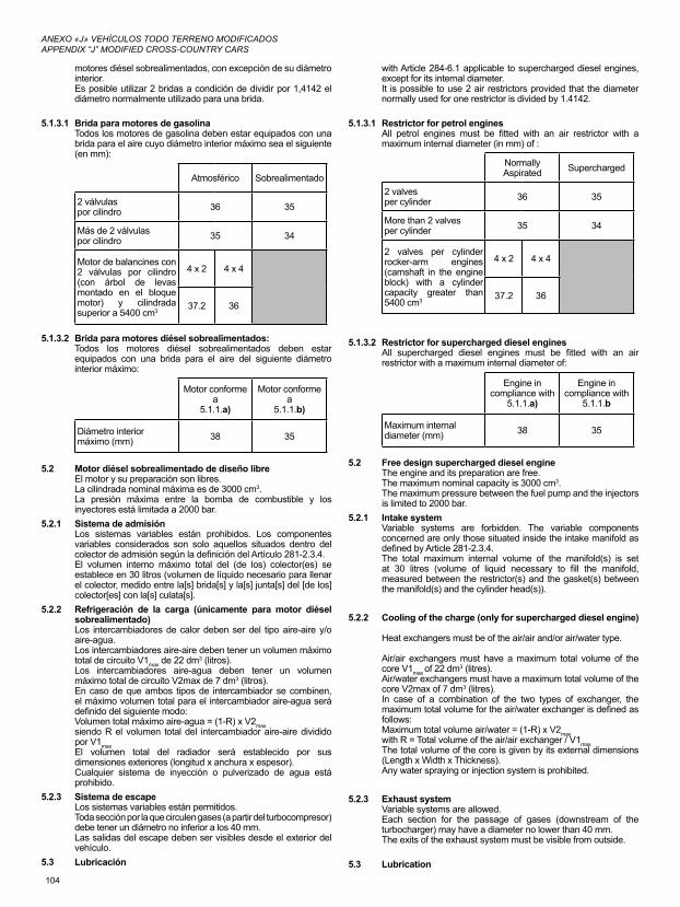
104
ANEXO «J» VEHÍCULOS TODO TERRENO MODIFICADOSAPPENDIX “J” MODIFIED CROSS-COUNTRY CARS
motores diésel sobrealimentados, con excepción de su diámetro interior.Es posible utilizar 2 bridas a condición de dividir por 1,4142 el diámetro normalmente utilizado para una brida.
5.1.3.1 Brida para motores de gasolinaTodos los motores de gasolina deben estar equipados con una brida para el aire cuyo diámetro interior máximo sea el siguiente (en mm):
Atmosférico Sobrealimentado
2 válvulaspor cilindro 36 35
Más de 2 válvulaspor cilindro 35 34
Motor de balancines con 2 válvulas por cilindro (con árbol de levas montado en el bloque motor) y cilindrada superior a 5400 cm3
4 x 2 4 x 4
37.2 36
5.1.3.2 Brida para motores diésel sobrealimentados:Todos los motores diésel sobrealimentados deben estar equipados con una brida para el aire del siguiente diámetro interior máximo:
Motor conformea
5.1.1.a)
Motor conformea
5.1.1.b)
Diámetro interior máximo (mm) 38 35
5.2 Motor diésel sobrealimentado de diseño libreEl motor y su preparación son libres.La cilindrada nominal máxima es de 3000 cm3.La presión máxima entre la bomba de combustible y los inyectores está limitada a 2000 bar.
5.2.1 Sistema de admisiónLos sistemas variables están prohibidos. Los componentes variables considerados son solo aquellos situados dentro del colector de admisión según la definición del Artículo 281-2.3.4.El volumen interno máximo total del (de los) colector(es) se establece en 30 litros (volumen de líquido necesario para llenar el colector, medido entre la[s] brida[s] y la[s] junta[s] del [de los] colector[es] con la[s] culata[s].
5.2.2 Refrigeración de la carga (únicamente para motor diésel sobrealimentado)Los intercambiadores de calor deben ser del tipo aire-aire y/o aire-agua.Los intercambiadores aire-aire deben tener un volumen máximo total de circuito V1max de 22 dm3 (litros).Los intercambiadores aire-agua deben tener un volumen máximo total de circuito V2max de 7 dm3 (litros).En caso de que ambos tipos de intercambiador se combinen, el máximo volumen total para el intercambiador aire-agua será definido del siguiente modo:Volumen total máximo aire-agua = (1-R) x V2maxsiendo R el volumen total del intercambiador aire-aire dividido por V1maxEl volumen total del radiador será establecido por sus dimensiones exteriores (longitud x anchura x espesor).Cualquier sistema de inyección o pulverizado de agua está prohibido.
5.2.3 Sistema de escapeLos sistemas variables están permitidos.Toda sección por la que circulen gases (a partir del turbocompresor) debe tener un diámetro no inferior a los 40 mm.Las salidas del escape deben ser visibles desde el exterior del vehículo.
5.3 Lubricación
with Article 284-6.1 applicable to supercharged diesel engines, except for its internal diameter.It is possible to use 2 air restrictors provided that the diameter normally used for one restrictor is divided by 1.4142.
5.1.3.1 Restrictor for petrol enginesAll petrol engines must be fitted with an air restrictor with a maximum internal diameter (in mm) of :
Normally Aspirated Supercharged
2 valvesper cylinder 36 35
More than 2 valvesper cylinder 35 34
2 valves per cylinder rocker-arm engines (camshaft in the engine block) with a cylinder capacity greater than 5400 cm3
4 x 2 4 x 4
37.2 36
5.1.3.2 Restrictor for supercharged diesel enginesAll supercharged diesel engines must be fitted with an air restrictor with a maximum internal diameter of:
Engine in compliance with
5.1.1.a)
Engine in compliance with
5.1.1.b
Maximum internal diameter (mm) 38 35
5.2 Free design supercharged diesel engineThe engine and its preparation are free.The maximum nominal capacity is 3000 cm3.The maximum pressure between the fuel pump and the injectors is limited to 2000 bar.
5.2.1 Intake systemVariable systems are forbidden. The variable components concerned are only those situated inside the intake manifold as defined by Article 281-2.3.4.The total maximum internal volume of the manifold(s) is set at 30 litres (volume of liquid necessary to fill the manifold, measured between the restrictor(s) and the gasket(s) between the manifold(s) and the cylinder head(s)).
5.2.2 Cooling of the charge (only for supercharged diesel engine)
Heat exchangers must be of the air/air and/or air/water type.
Air/air exchangers must have a maximum total volume of the core V1max of 22 dm3 (litres).Air/water exchangers must have a maximum total volume of the core V2max of 7 dm3 (litres).In case of a combination of the two types of exchanger, the maximum total volume for the air/water exchanger is defined as follows:Maximum total volume air/water = (1-R) x V2maxwith R = Total volume of the air/air exchanger / V1maxThe total volume of the core is given by its external dimensions (Length x Width x Thickness).Any water spraying or injection system is prohibited.
5.2.3 Exhaust systemVariable systems are allowed.Each section for the passage of gases (downstream of the turbocharger) may have a diameter no lower than 40 mm.The exits of the exhaust system must be visible from outside.
5.3 Lubrication
105
ANEXO «J» VEHÍCULOS TODO TERRENO MODIFICADOSAPPENDIX “J” MODIFIED CROSS-COUNTRY CARS
La bomba de aceite, la caja del filtro de aceite, el radiador, el intercambiador aceite-agua, los conductos, el termostato, el cárter de aceite y los filtros de la bomba son libres.La utilización de un sistema de lubricación del motor por cárter seco está autorizada. Ni el depósito ni las canalizaciones de aceite deben situarse dentro del habitáculo o en el maletero.La presión de aceite puede aumentarse cambiando el muelle de la válvula de descarga.Si el sistema de lubricación previera una salida al aire libre, esta deberá estar equipada de tal forma que los reflujos de aceite se acumulen en un recipiente recuperador.Este debe tener una capacidad de 2 dm3 (litros) para vehículos con una cilindrada igual o inferior a 2000 cm3 y 3 dm3 (litros) para vehículos con una cilindrada superior a 2000 cm3.Dicho recipiente será de plástico translúcido o tendrá una ventana transparente.Es posible instalar un separador aire-aceite en el exterior del motor (capacidad máxima: 1 litro, salvo si está integrado en el recipiente recuperador), de conformidad con el Dibujo 255-3.El retorno del aceite del recipiente recuperador hacia el motor solamente podrá hacerse por gravedad.Se permite el montaje de uno o varios ventiladores para la refrigeración del aceite del motor, siempre que esto no implique ningún efecto aerodinámico.
5.4 Refrigeración del carburanteEl montaje de refrigeración de carburante se autoriza en el circuito de retorno del carburante hacia el depósito.
ARTÍCULO 6 - TRANSMISIÓNEl sistema de transmisión debe ser activado y controlado exclusivamente por el conductor.6.1 Caja de cambios y caja de transferencia
La caja de cambios es libre, pero el cambio de velocidad debe realizarse sin ningún otro intermediario en la cadena de transmisión.
6.1.1 Mecanismos de accionamiento de la caja de cambios de tipo «secuencial»Estarán permitidos con las siguientes condiciones:• El sistema debe ser exclusivamente mecánico, sin ninguna
asistencia.• La cantidad de marchas hacia adelante está limitada a 6.• Se permite un sistema de corte de inyección y/o de encendido
activado mecánicamente por el cambio de marchas.6.1.2 Caja de cambios de serie con accionamiento mecánico en H
La cantidad de marchas hacia adelante es libre, pero debe mantenerse idéntica a la original.
6.1.3 Caja automáticaSolo se permiten las cajas automáticas que utilicen un convertidor de par.
6.2 EmbragueLibre.
6.3 Relaciónfinal,diferenciales(4x4)Libres.Los diferenciales deben ser de tipo epicicloidal de una sola etapa.Los dispositivos autoblocantes deben ser enteramente mecánicos (con discos) y/o de acoplamiento viscoso.El establecimiento de sus parámetros de funcionamiento debe ser exclusivamente hecho con la ayuda de herramientas mientras el vehículo esté detenido.Los dispositivos autoblocantes pueden tener un actuador que permita únicamente el blocaje total del (de los) diferencial(es).
6.4 Árboles de transmisiónLos árboles de transmisión son libres, pero deberán ser de acero.
6.5 LubricaciónSe permite un dispositivo adicional de lubricación y de refrigeración del aceite (bomba de circulación, radiador, y tomas de aire) en las mismas condiciones especificadas en el Artículo 285-5.3.Debe conservarse el sistema de lubricación original para los componentes de serie.La única modificación permitida en el cárter de caja de cambios/diferencial es aquella destinada a realizar las adaptaciones necesarias para el montaje de un sistema adicional de
Oil pump, oil filter housing, radiator, oil/water exchanger, lines, thermostat, sump and pump strainers are free.The use of a system of lubrication by dry sump is authorised. The oil chamber together with the lines must not be located in the cockpit or in the baggage compartment.Oil pressure may be increased by changing the discharge valve spring.If the lubrication system includes an open type sump breather, it must be equipped in such a way that the oil flows into a catch tank.This must have a minimum capacity of 2 dm3 (litres) for cars with a cubic capacity equal to or below 2000 cm3 and 3 dm3 (litres) for cars with a cubic capacity of over 2000 cm3.
This container must either be made of translucent plastic or include a transparent panel.An air/oil separator may be mounted outside the engine (maximum capacity 1 litre unless integrated into the catch tank) in accordance with Drawing 255-3.The oil must flow from the oil catch tank towards the engine by the force of gravity alone.The fitting of one or several ventilators for cooling the engine oil is authorised, provided that this does not have any aerodynamic effect.
5.4 Fuel coolingThe fitting of fuel coolers is authorised on the return circuit to the tank.
ARTICLE 6 - TRANSMISSIONThe transmission system must be activated and controlled only by the driver.6.1 Gearbox and transfer box
The design of the gearbox is free but the gear change may not be made by any other means in the transmission chain.
6.1.1 "Sequential" type gearbox controlPermitted under the following conditions :• The system must be exclusively mechanical without any
assistance.• The number of forward gears is limited to 6.• An engine ignition and/or injection cut-off system activated
mechanically by the gear change is allowed.
6.1.2 Series H-pattern mechanically controlled gearboxThe number of forward gears is free but must remain identical to the original.
6.1.3 Automatic gearboxOnly automatic boxes using a torque converter are authorised.
6.2 ClutchFree.
6.3 Final drive, differential (4x4)Free.The differentials must be of the single stage epicyclical type.The self-locking devices must be entirely mechanical (with plates) and/or visco coupling.The setting of their functioning parameters must be made exclusively with the use of tools when the car is immobilised.The self-locking devices may have an actuator allowing only the locking of the differential(s).
6.4 Transmission shaftsTransmission shafts are free but must be made of steel.
6.5 LubricationAn additional lubrication and oil cooling device is allowed (circulation pump, radiator, and air intakes) under the same conditions as for Article 285-5.3.For production components, the original lubrication principle must be retained.The only modification authorised on the gearbox / differential housing is the one intended for adapting the additional lubrication system.
106
ANEXO «J» VEHÍCULOS TODO TERRENO MODIFICADOSAPPENDIX “J” MODIFIED CROSS-COUNTRY CARS
lubricación.
ARTÍCULO 7 - SUSPENSIÓN7.1 Generalidades
La suspensión es libre, pero el uso de suspensiones activas está prohibido (cualquier sistema que permita el control de la flexibilidad, amortiguación, altura y/o comportamiento de la suspensión cuando el vehículo está en movimiento).
7.2 Muelles y amortiguadoresEl ajuste de los muelles y/o de los amortiguadores desde el habitáculo está prohibido.Dicho ajuste debe ser posible únicamente cuando el vehículo se encuentra detenido y mediante el uso de herramientas.El dispositivo de ajuste debe estar situado en el propio amortiguador o en su reserva de gas.Cualquier conexión entre los amortiguadores está prohibida. Las únicas conexiones permitidas son los puntos de fijación del amortiguador que pasan por el chasis y no cumplen ninguna otra función.
7.3 Barras estabilizadorasSolo se permite una barra estabilizadora por eje.El ajuste de las barras estabilizadoras desde el habitáculo está prohibido.El sistema de barras estabilizadoras debe ser exclusivamente mecánico, y no debe ser posible activarlo o desactivarlo.Cualquier conexión entre las barras estabilizadoras delantera y trasera está prohibida.
7.4 Recorrido de la suspensiónPara los 4x4, el recorrido vertical de las suspensiones está limitado como sigue:- 300 mm para un eje rígido de tipo «banjo» (el eje de salida del
diferencial coincide con el eje de las ruedas). (Ver el Dibujo 285-2).
- 250 mm para otros tipos de transmisión.El método para medir el recorrido es el siguiente:- Para suspensiones de ruedas independientes:
El vehículo debe estar sobre borriquetas con los conjuntos resorte/amortiguador desmontados.La rueda debe poder moverse de tope de acero a tope de acero.El recorrido es la media del desplazamiento vertical de dos puntos del plano medio de la rueda opuestos diametralmente sobre un plano vertical.
- Para suspensiones de eje rígido:El vehículo debe estar sobre borriquetas con los conjuntos resorte/amortiguador desmontados y el eje rígido sujeto por las correas de limitación de recorrido o los topes inferiores.Las ruedas deben moverse simultáneamente desde el tope de acero superior al tope de acero inferior.El recorrido de la suspensión corresponde al desplazamiento vertical de las ruedas.
ARTÍCULO 8 - RUEDAS Y NEUMÁTICOSPara vehículos 4x4, solo se autorizan ruedas hechas de aleación de aluminio fundido y que pesen más de 13kg.Las ruedas completas deben alojarse en la carrocería (cf. Artículo 3.1) y tener un diámetro máximo de 940 mm para los vehículos 4x2 y de 810 mm para los 4x4.El diámetro debe medirse en una rueda nueva suministrada por el fabricante.Se prohíbe el uso de neumáticos de motocicleta.El montaje de piezas intermedias entre llantas y neumáticos está prohibido.No es necesario que todas las ruedas sean del mismo diámetro.Se prohíbe la fijación de ruedas mediante tuerca central.La utilización de un sistema para inflar-desinflar los neumáticos mientras el vehículo está en movimiento está prohibida, salvo para vehículos 4x2.Para vehículos 4x4, esta operación de inflado-desinflado debe ser efectuada obligatoriamente con el vehículo parado.Solamente se permite conectar un sistema a las ruedas durante el tiempo que requiera esta operación mediante un tubo flexible y con una válvula por rueda.A fin de ajustar la presión de los neumáticos, la introducción o extracción de aire se hará mediante una válvula de tipo convencional con un roscado de fijación de tipo VG5 y proveniente de un vehículo utilitario ligero de producción en serie.Solo se permite una válvula por rueda y dicha válvula deberá estar fijada a la llanta en un solo orificio con un diámetro máximo de 12 mm,
ARTICLE 7 - SUSPENSION7.1 General
The suspension is free but it is forbidden to use active suspension (any system which allows control of flexibility, damping, height and/or attitude of the suspension when the car is in motion).
7.2 Springs and shock absorbersThe adjustment of the springs and/or shock absorbers from the cockpit is forbidden.It must only be possible when the car is not in motion and only with the use of tools.The adjustment device must be situated on the shock absorber or its gas reserve.Any connections between dampers are forbidden. The only connections permitted are the damper fixing points passing through the frame; these must have no other function.
7.3 Anti-roll barsOnly one anti-roll bar per axle is permitted.The adjustment of the anti-roll bars from the cockpit is forbidden.The anti-roll bar systems must be exclusively mechanical, with no activation or deactivation possible.Any connections between front and rear anti-roll bars are forbidden.
7.4 Suspension travelVertical suspension travel for 4x4 is limited to :- 300 mm (see Drawing 285-2) for a “banjo” type rigid axle (the
axis of the differential outlet merging with the centre line of the wheels).
- 250 mm for other types of transmission.The method for measuring the travel is the following:- For suspensions with independent wheels:
The vehicle must be on stands with the spring/shock absorber units dismounted.The wheel must be moved from steel bump stop to steel bump stop.The travel is the average of the vertical displacements of two points of the median plane of the wheel diametrically opposed on a vertical plane.
- For suspension with rigid axles:The vehicle must be on stands with the spring/shock absorbers units dismounted and with the rigid axle prevented from moving downward by travel limitation straps or the lower bump stop.The wheels must be moved simultaneously from the upper steel bump stop to the lower steel bump stop.The travel is the vertical displacement of the wheels.
ARTICLE 8 - WHEELS AND TYRESOnly wheels made from cast aluminium alloy and weighing more than 13kg are authorised for 4x4.Complete wheels must be housed within the bodywork (cf. Article 3.1), and must have a maximum diameter of 940 mm for 4x2 and 810 mm for 4x4.The diameter must be measured on the new tyre specified by the manufacturer.The use of tyres intended for motor cycles is forbidden.The fitting of intermediate parts between the wheels and the tyres is forbidden.The wheels do not have to be of the same diameter.Central nut wheel fixing is forbidden.The use of any system for inflating / deflating the tyres when the car is in motion is forbidden, except for 4x2.For 4x4, the inflating / deflating operation must only be carried out while the car is not in motion.
The only system authorised is a system connected to the wheels through a flexible tube during the operation and connected to one valve per wheel.
In order to adjust the tyre pressure, any air going in or out must pass through a conventional type of valve coming from a series light utility vehicle and having a VG5 type screw thread.
Only one valve is allowed per wheel and it must be fixed to the rim by a
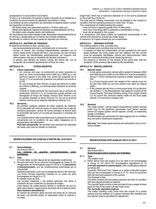
107
ANEXO «J» VEHÍCULOS TODO TERRENO MODIFICADOSAPPENDIX “J” MODIFIED CROSS-COUNTRY CARS
emplazada en la cara exterior de la llanta.El tubo y su manómetro de presión pueden colocarse en el habitáculo a condición de que la presión de utilización sea inferior a 10bar.Las botellas de aire comprimido que alimenten el sistema deben cumplir las siguientes condiciones:- No deben tener una capacidad superior a 15 litros cada una.- Deben tener fijaciones capaces de soportar una desaceleración de 25 g.- No deben estar situadas dentro del habitáculo.
Se recomienda que estas botellas estén dispuestas transversalmente en el vehículo y aseguradas por al menos dos correas metálicas.Se permite un máximo de tres ruedas de repuesto por vehículo.
ARTÍCULO 9 - SISTEMA DE FRENADOEl sistema de frenado es libre, siempre que:
- sea exclusivamente activado y controlado por el conductor;- incluya, al menos, dos circuitos independientes operados por el
mismo pedal (entre el pedal del freno y las pinzas, los dos circuitos deben poder ser identificables separadamente, sin ninguna otra interconexión más que el repartidor de frenada mecánico);
- la presión sea idéntica en ambas ruedas del mismo eje, con la excepción de la presión generada por el freno de mano.
ARTÍCULO 10 - OTROS ASUNTOS10.1 Casos especiales
• Un vehículo 4x4 que, en producción en serie, presente un peso en vacío comprendido entre 2500 kg y 3500 kg y una anchura superior a los 2000 mm, podrá ser aceptado en el Grupo T1 si el constructor presenta una petición por escrito a la FIA.En una prueba de Todo Terreno, el peso del vehículo no debe ser inferior a 2800 kg, y el vehículo debe mantener su anchura original.
• Cuando el chasis proviene del monocasco de un vehículo de producción (Artículo 3.1), el Constructor puede solicitar una derogación al Grupo de Trabajo Técnico Todo Terreno si no es posible respetar la altura (Artículo 3.2.1b) y/o la anchura interior mínima de los asientos delanteros (Artículo 3.3).
10.2 SensoresSe prohíbe cualquier sistema de radar, sistema de medición de la velocidad del vehículo (salvo la rueda fónica de la caja de cambios) giroscopio, sensor de fuerza (excepto el sensor para el encendido del motor y/o el corte de inyección) o indicador de limitador.Los acelerómetros están permitidos para la adquisición de datos únicamente con la condición de que estén integrados en el equipamiento del salpicadero.Para 4x2 únicamente: Se permiten dos sensores de velocidad de rueda, pero solo en ruedas no motrices.
MODIFICACIONES APLICABLES A PARTIR DEL 01/01/2013
5.1 GeneralidadesVer Artículo 282-3. Los motores de gasolina sobrealimentados están prohibidos.
5.1.1 TipoEl motor debe cumplir alguna de las siguientes condiciones:
a. Provenir del motor de un vehículo homologable en Grupo N, GT (Reglamento de Homologación para GT 2012) o T2 (atmosférico o sobrealimentado), con las modificaciones autorizadas por el Artículo284.Deberá presentarse, junto con el pasaporte técnico del vehículo, una Ficha Técnica específica, basada en un motor de serie homologable en Grupo N o T2.El volante motor es libre.Las correas (cadenas) y las poleas (piñones) son libres a condición de que conserven su principio de origen.La(s) tapa(s) de culata es(son) libre(s) a condición de que su peso sea superior o igual al peso de la tapa de la culata de serie.Para motores atmosféricos:El colector de admisión debe provenir del motor de un vehículo de serie y se permite añadir un espaciador entre el colector y la culata.
single hole, which has a maximum diameter of 12 mm and is positioned on the outer face of the rim.The tube and its inflating manometer may be situated in the cockpit on condition that the operating pressure is lower than 10 bars.The compressed air bottles feeding the system:- must not have a capacity greater than 15 litres each,- must have mountings able to withstand a deceleration of 25 g,- must not be situated in the cockpit.
It is compulsory that these bottles be positioned transversally in the vehicle and secured by at least two metal straps.A maximum of 3 spare wheels per car is authorised.
ARTICLE 9 - BRAKING SYSTEMThe braking system is free, provided that:
- it is activated and controlled only by the driver,- it includes at least two independent circuits operated by the same
pedal (between the brake pedal and the callipers, the two circuits must be separately identifiable, without any interconnection other than the mechanical braking force balancing device),
- the pressure is identical on the wheels of the same axle, with the exception of the pressure generated by the handbrake.
ARTICLE 10 - MISCELLANEOUS10.1 Special cases
• A 4x4 series production vehicle with a weight of between 2500 and 3500 kg and a width of over 2000 mm, may be accepted in Group T1 if the manufacturer submits a written request to the FIA.In a Cross-Country event, the weight of this vehicle must not be less than 2800 kg, and the vehicle may retain its original width.
• If the chassis derives from a monocoque body of a production car (Article 3.1), the Manufacturer may apply for a waiver to the Cross-Country Technical Working Group if the height (Article 3.2.1b) and/or the minimum interior width for the front seats (Article 3.3) cannot be complied with.
10.2 SensorsAny radar system, vehicle speed measurement system (except pulse ring on the gearbox), gyroscope, load sensor (except sensor for engine ignition and/or injection cut-off), or restraining gauge is forbidden.Accelerometers are authorized for data logging only on condition they are built-in dashboard equipment.
4x2 only: Two wheel speed sensors are authorised, only on non-driven wheels.
MODIFICATIONS APPLICABLES ON 01.01.2013
5.1 GeneralSee Article 282-3.Supercharged petrol engines are forbidden.
5.1.1 TypeThe engine must:
a. Either derive from the engine of a car able to be homologated in Group N, GT (2012 GT homologation regulations) or T2 (normally aspirated or supercharged), with modifications allowed by Article 284.A specific Technical Form, based on a series production engine that can be homologated in Group N or T2, must be produced with the technical passport of the vehicle.The flywheel is free.The belts (chains) and the pulleys (pinions) are free on condition that the original principle is retained.The cylinder head cover(s) is free provided it has a weight at least equal to that of the series cylinder head cover.For normally aspirated engines:The intake manifold must come from the engine of a series vehicle and the addition of a spacer between the manifold and the cylinder head is permitted for adjustment.
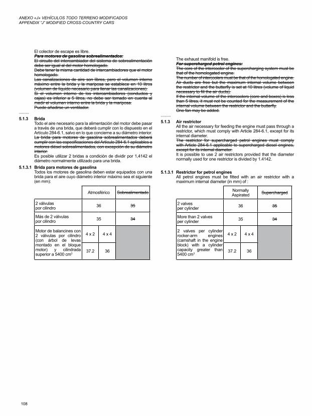
108
ANEXO «J» VEHÍCULOS TODO TERRENO MODIFICADOSAPPENDIX “J” MODIFIED CROSS-COUNTRY CARS
El colector de escape es libre.Para motores de gasolina sobrealimentados:El circuito del intercambiador del sistema de sobrealimentación debe ser igual al del motor homologado.Debe tener la misma cantidad de intercambiadores que el motor homologado.Las canalizaciones de aire son libres, pero el volumen interno máximo entre la brida y la mariposa se establece en 10 litros (volumen de líquido necesario para llenar las canalizaciones).Si el volumen interno de los intercambiadores (conductos y cajas) es inferior a 5 litros, no debe ser tomado en cuenta al medir el volumen interno entre la brida y la mariposa.Puede añadirse un ventilador.
.........5.1.3 Brida
Todo el aire necesario para la alimentación del motor debe pasar a través de una brida, que deberá cumplir con lo dispuesto en el Artículo 284-6.1, salvo en lo que concierne a su diámetro interior.La brida para motores de gasolina sobrealimentados deberá cumplir con las especificaciones del Artículo 284-6.1 aplicables a motores diésel sobrealimentados, con excepción de su diámetro interior.Es posible utilizar 2 bridas a condición de dividir por 1,4142 el diámetro normalmente utilizado para una brida.
5.1.3.1 Brida para motores de gasolinaTodos los motores de gasolina deben estar equipados con una brida para el aire cuyo diámetro interior máximo sea el siguiente (en mm):
Atmosférico Sobrealimentado
2 válvulaspor cilindro 36 35
Más de 2 válvulaspor cilindro 35 34
Motor de balancines con 2 válvulas por cilindro (con árbol de levas montado en el bloque motor) y cilindrada superior a 5400 cm3
4 x 2 4 x 4
37.2 36
The exhaust manifold is free.For supercharged petrol engines:The core of the intercooler of the supercharging system must be that of the homologated engine.The number of intercoolers must be that of the homologated engine.Air ducts are free but the maximum internal volume between the restrictor and the butterfly is set at 10 litres (volume of liquid necessary to fill the air ducts).If the internal volume of the intercoolers (core and boxes) is less than 5 litres, it must not be counted for the measurement of the internal volume between the restrictor and the butterfly.One fan may be added.
.........5.1.3 Air restrictor
All the air necessary for feeding the engine must pass through a restrictor, which must comply with Article 284-6.1, except for its internal diameter.The restrictor for supercharged petrol engines must comply with Article 284-6.1 applicable to supercharged diesel engines, except for its internal diameter.It is possible to use 2 air restrictors provided that the diameter normally used for one restrictor is divided by 1.4142.
5.1.3.1 Restrictor for petrol enginesAll petrol engines must be fitted with an air restrictor with a maximum internal diameter (in mm) of :
Normally Aspirated Supercharged
2 valvesper cylinder 36 35
More than 2 valvesper cylinder 35 34
2 valves per cylinder rocker-arm engines (camshaft in the engine block) with a cylinder capacity greater than 5400 cm3
4 x 2 4 x 4
37.2 36
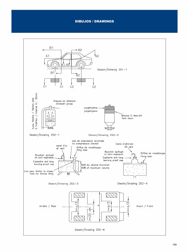
109
DIBUJOS / DRAWINGS
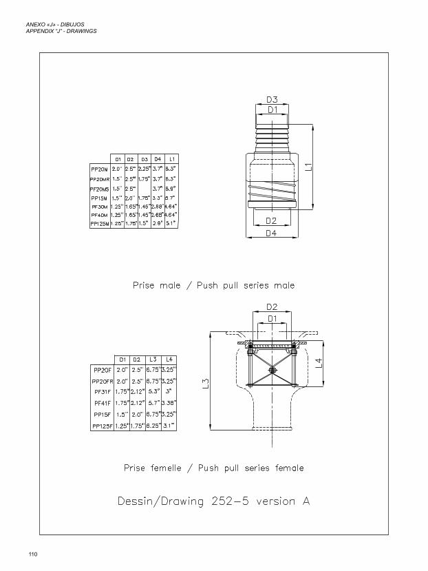
110
ANEXO «J» - DIBUJOSAPPENDIX “J” - DRAWINGS
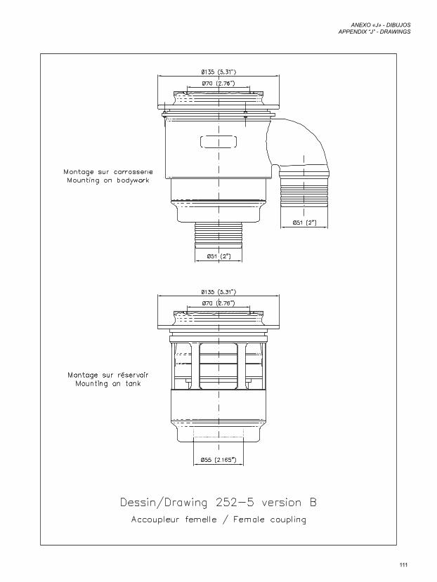
111
ANEXO «J» - DIBUJOSAPPENDIX “J” - DRAWINGS
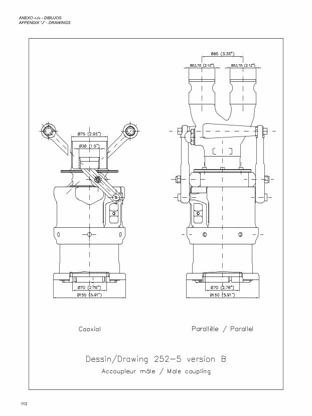
112
ANEXO «J» - DIBUJOSAPPENDIX “J” - DRAWINGS
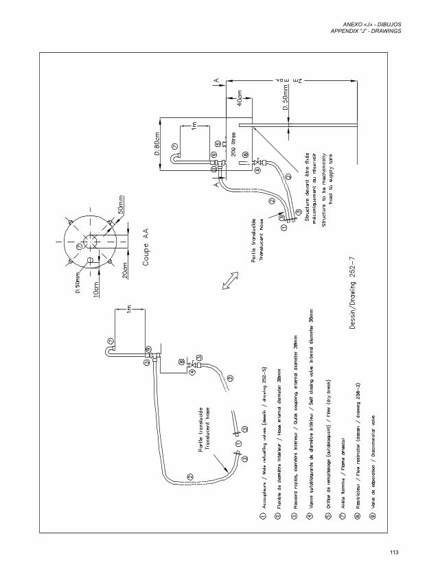
113
ANEXO «J» - DIBUJOSAPPENDIX “J” - DRAWINGS
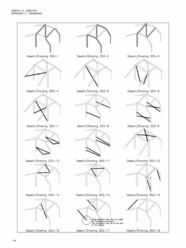
114
ANEXO «J» - DIBUJOSAPPENDIX “J” - DRAWINGS
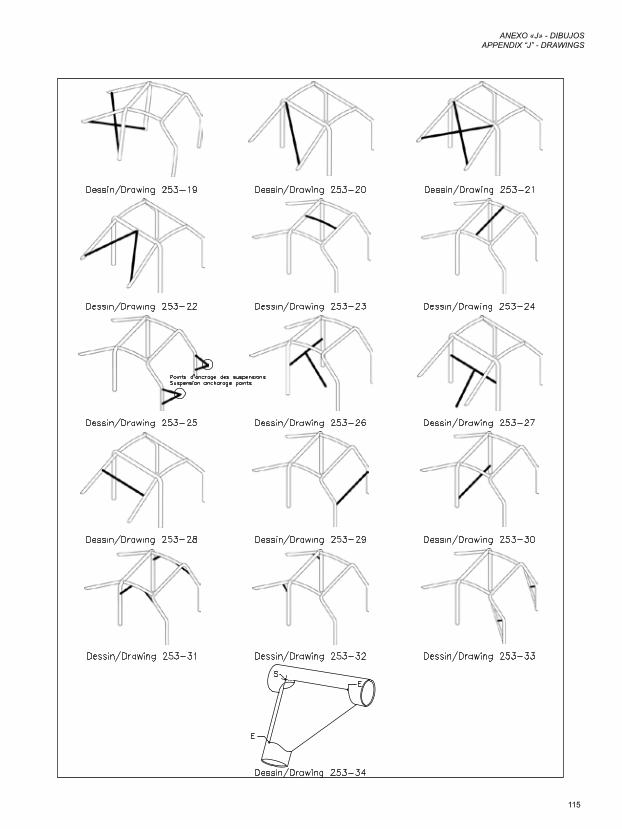
115
ANEXO «J» - DIBUJOSAPPENDIX “J” - DRAWINGS
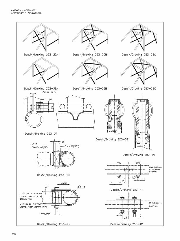
116
ANEXO «J» - DIBUJOSAPPENDIX “J” - DRAWINGS
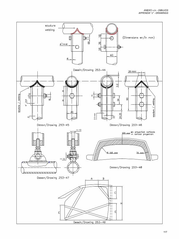
117
ANEXO «J» - DIBUJOSAPPENDIX “J” - DRAWINGS
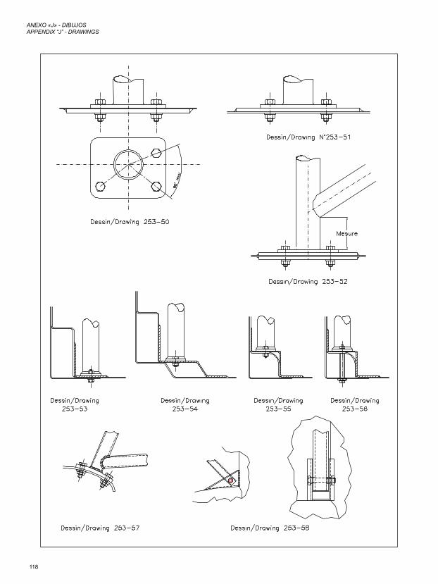
118
ANEXO «J» - DIBUJOSAPPENDIX “J” - DRAWINGS
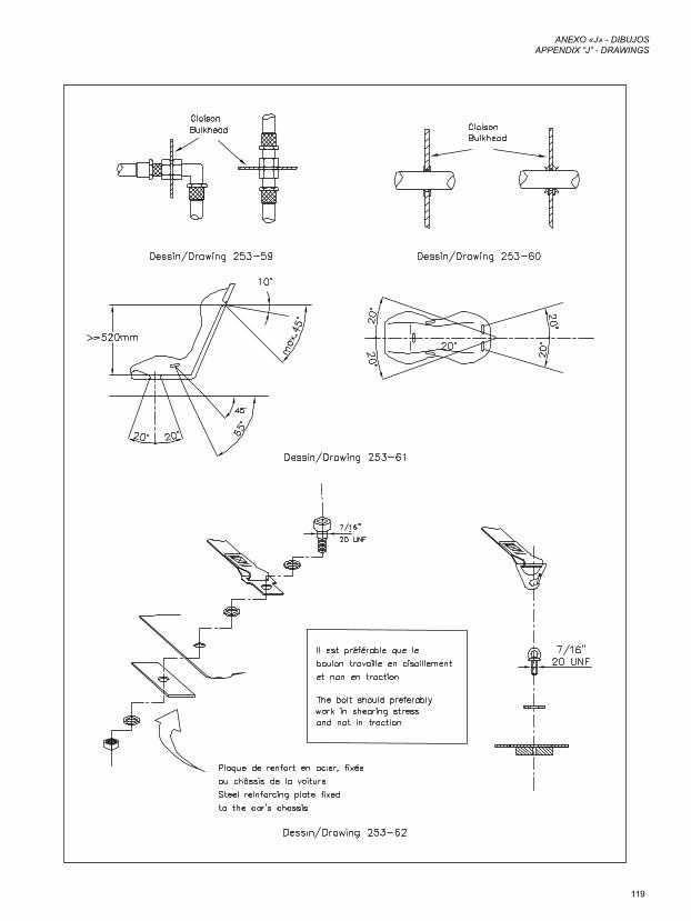
119
ANEXO «J» - DIBUJOSAPPENDIX “J” - DRAWINGS
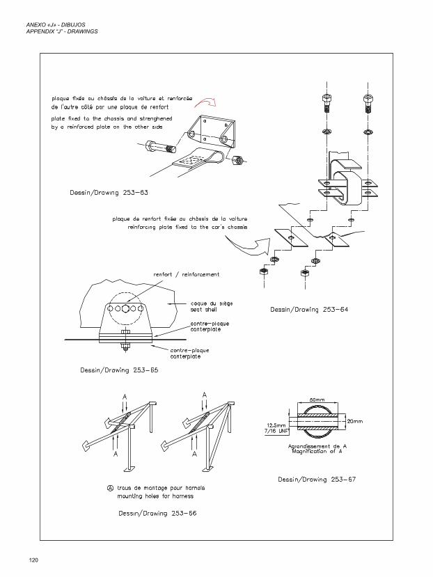
120
ANEXO «J» - DIBUJOSAPPENDIX “J” - DRAWINGS
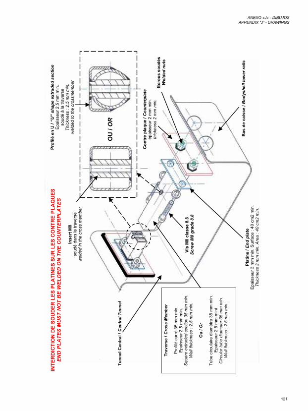
121
ANEXO «J» - DIBUJOSAPPENDIX “J” - DRAWINGS
Ba
s d
e c
ais
se
/ B
od
ys
he
ll lo
we
r ra
ils
Co
ntre
p
la
qu
e / C
ou
nte
rp
la
te
ép
ais
se
ur 2
m
m m
in.
th
ickn
ess 2
m
m m
in.
OU
/ OR
Ec
ro
us
s
ou
dé
s
We
ld
ed
n
uts
Pla
tin
e / E
nd
p
la
te
Ep
ais
se
ur 3
m
m m
in. S
urfa
ce
: 4
0 cm
2 m
in.
Th
ickn
ess 3
m
m m
in.
Are
a : 4
0 cm
2 m
in
.
Vis
M
8 c
la
ss
e 8
.8
Sc
re
w M
8 g
ra
de
8
.8
Tu
nn
el C
en
tra
l / C
en
tra
l T
un
ne
l
Tra
ve
rs
e / C
ro
ss
M
em
be
r
Pro
filé
ca
rré
3
5 m
m m
in.
Ep
ais
se
ur 2
,5
m
m m
in.
Sq
ua
re
e
xtru
de
d se
ctio
n 3
5 m
m m
in.
Wa
ll th
ickn
ess : 2
.5
m
m m
in
.
Ou
/ O
r
Tu
be
circu
laire
d
iam
ètre
3
5 m
m m
in.
Ep
ais
se
ur 2
.5
m
m m
ini
Cir
cu
lar tu
be
d
iam
ete
r 3
5 m
m m
in.
Wa
ll th
ickn
ess : 2
.5
m
m m
in
.
In
se
rt M
8
so
ud
é d
an
s la
tra
ve
rse
we
lde
d in
th
e cro
ss m
em
be
r
Pro
filé
e
n U
/ “U
” s
ha
pe
e
xtru
de
d s
ec
tio
n
Ep
ais
se
ur 2
,5
m
m m
in.
so
ud
é à
la
tra
ve
rse
Th
ickn
ess : 2
.5
m
m m
in.
we
lde
d to
th
e cro
ssm
em
be
r
IN
TE
RD
IC
TIO
N D
E S
OU
DE
R L
ES
P
LA
TIN
ES
S
UR
L
ES
C
ON
TR
E P
LA
QU
ES
EN
D P
LA
TE
S M
US
T N
OT
B
E W
EL
DE
D O
N T
HE
C
OU
NT
ER
PL
AT
ES
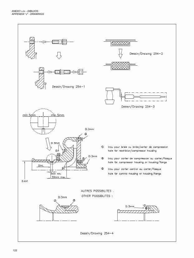
122
ANEXO «J» - DIBUJOSAPPENDIX “J” - DRAWINGS
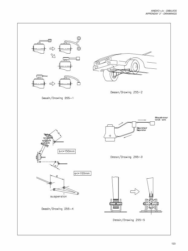
123
ANEXO «J» - DIBUJOSAPPENDIX “J” - DRAWINGS
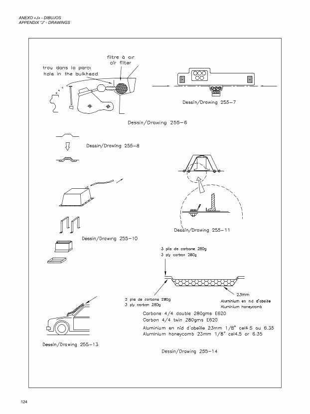
124
ANEXO «J» - DIBUJOSAPPENDIX “J” - DRAWINGS
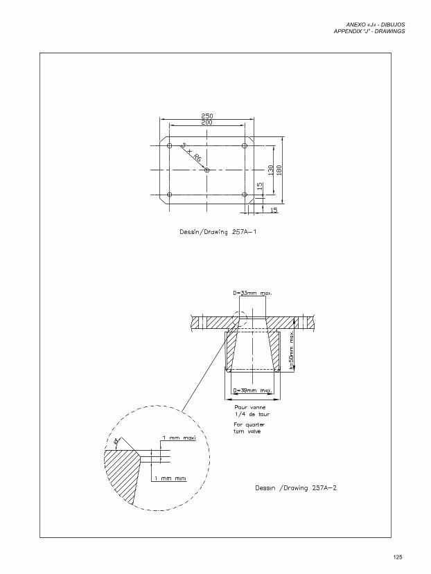
125
ANEXO «J» - DIBUJOSAPPENDIX “J” - DRAWINGS
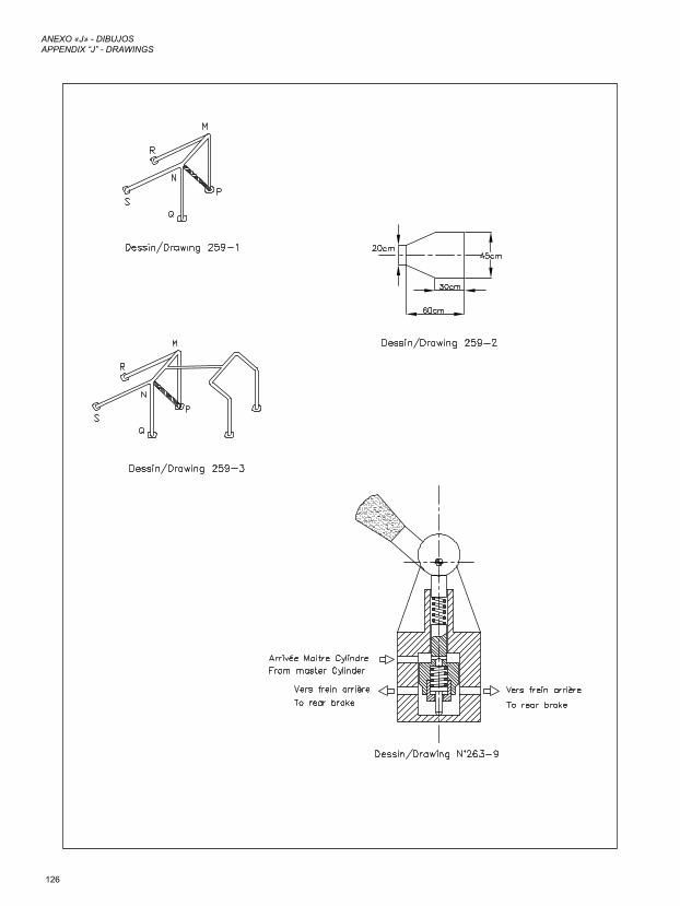
126
ANEXO «J» - DIBUJOSAPPENDIX “J” - DRAWINGS
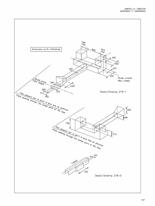
127
ANEXO «J» - DIBUJOSAPPENDIX “J” - DRAWINGS
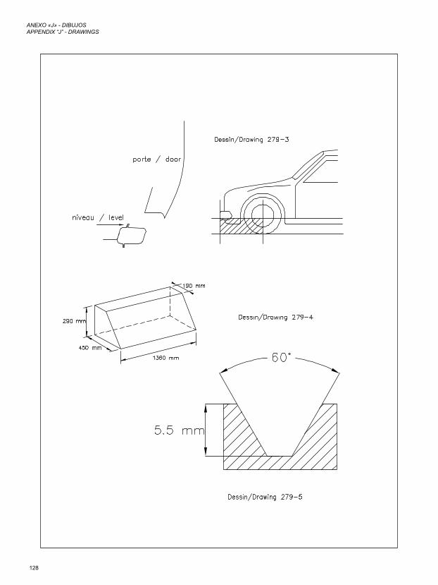
128
ANEXO «J» - DIBUJOSAPPENDIX “J” - DRAWINGS
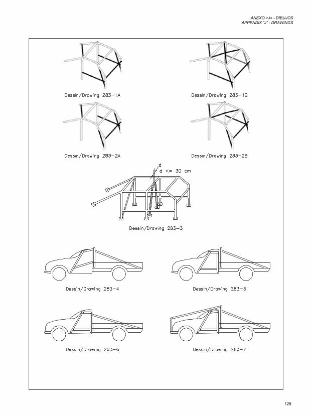
129
ANEXO «J» - DIBUJOSAPPENDIX “J” - DRAWINGS
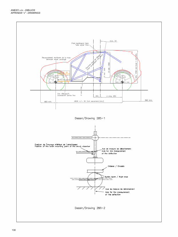
130
ANEXO «J» - DIBUJOSAPPENDIX “J” - DRAWINGS
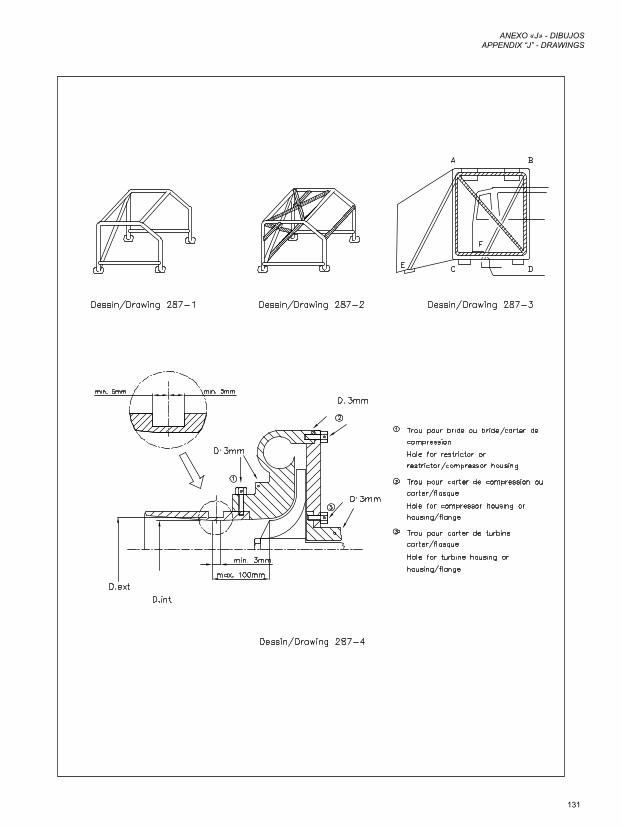
131
ANEXO «J» - DIBUJOSAPPENDIX “J” - DRAWINGS
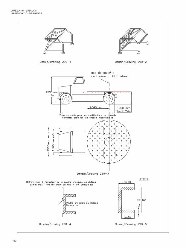
132
ANEXO «J» - DIBUJOSAPPENDIX “J” - DRAWINGS
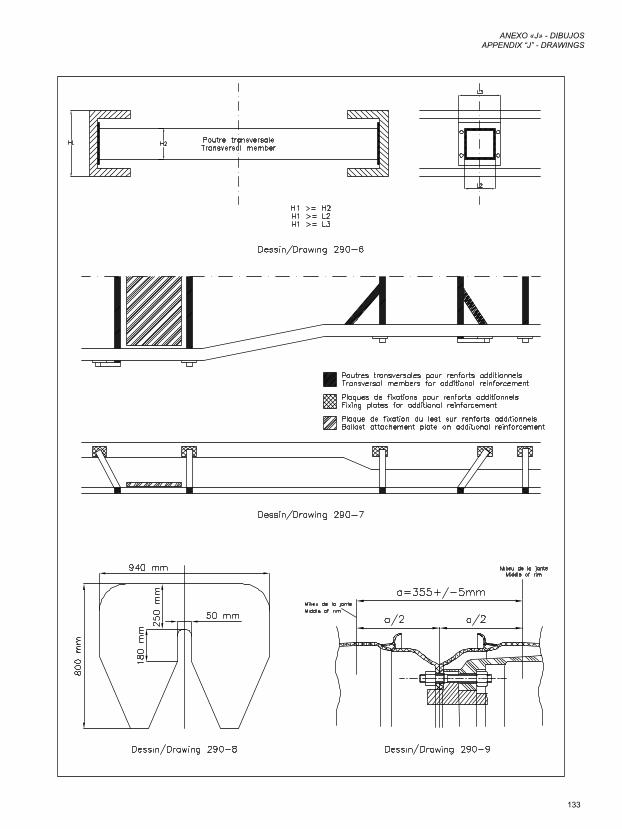
133
ANEXO «J» - DIBUJOSAPPENDIX “J” - DRAWINGS