and control requirements for electromagnetic...
TRANSCRIPT

SSP 30242 Revision F
National Aeronautics and Space AdministrationSpace Station Program OfficeJohnson Space Center Houston, Texas
Space Station Cable/Wire Designand Control Requirements forElectromagnetic Compatibility
Revision F
31 July 2002
International Space Station
esaeuropean space agency
National Space DevelopmentAgency of Japan

SSP 30242 Revision F 31 July 2002
REVISION AND HISTORY PAGE
REV. DESCRIPTION PUB.DATE
– SDR Version 03–07–94
C Revision C (Reference SSCBD 000008 R1, Eff. 6–03–94) Revised to Transition from Freedom Program to ISS. Changes include extensive simplification of requirements and scope. 09–30–94
D Revision D (SSCD 000263, EFF. 09–04–96) 01–29–97Administrative Update
DCN 001 incorporates SSCN 001261 07–20–98
DCN 002 incorporates SSCN 001594 06–09–99
E Revision E incorporates SSCD 001481 Eff. 12–10–99 08–25–99
DCN 003 incorporates SSCN 001920 08–30–99
DCN 004 incorporates SSCD 003213 Eff. 06–28–00 04–13–01
DCN 007 incorporates SSCN 005263 10–23–01
The following DCN has been cancelled. The content of the SSCN authorizingrelease of the DCN has been incorporated into Revision F.
DCN 005 incorporates SSCN 006568 Administrative Cancel
F Revision F incorporates SSCNs 006568 and 003282 12–06–02
ERU: /s/ M. Hehn 12–06–02

SSP 30242 Revision F 31 July 2002
i
INTERNATIONAL SPACE STATION PROGRAM
SPACE STATION CABLE/WIRE DESIGN AND CONTROL REQUIREMENTS FORELECTROMAGNETIC COMPATIBILITY
31 JULY 2002

SSP 30242 Revision F 31 July 2002
ii
PREFACE
This document contains wiring and cabling requirements for electromagnetic compatibility. Thecontents of this document are intended to be consistent with requirements as defined in the SSP41000 and SSP 30243. Space Station Cable/Wire Design and Control Requirements forElectromagnetic Compatibility shall be implemented on all SSP contractual and internalactivities. This document is under control of the Space Station Control Board.

SSP 30242 Revision F 31 July 2002
iii
INTERNATIONAL SPACE STATION PROGRAM OFFICE
SPACE STATION CABLE/WIRE DESIGN AND CONTROL REQUIREMENTS FORELECTROMAGNETIC COMPATIBILITY
31 JULY 2002
CONCURRENCE
PREPARED BY:
CHECKED BY:
SIGNATURE
SUPERVISED BY
PRINT NAME ORGN
DATE
SIGNATURE
PRINT NAME ORGN
DATE
SUPERVISED BY
SIGNATURE
PRINT NAME ORGN
DATE
SIGNATURE
PRINT NAME ORGN
DATE
DQA:
SIGNATURE
PRINT NAME ORGN
DATE
(BOEING):
(NASA):
Edward Jablonski
Cindy George
AG–92–J377
AG–92–J377
AG–92–J377
AG–92–J343Rebecca Chaky
Kreg Rice
EL23Matt McCollum
/s/ Cindy George 11/26/02

SSP 30242 Revision F 31 July 2002
iv
NASA/ASI
INTERNATIONAL SPACE STATION PROGRAM
SPACE STATION ELECTROMAGNETIC CABLE/WIRE DESIGN AND CONTROLREQUIREMENTS FOR ELECTROMAGNETIC COMPATIBILITY
31 JULY 2002
DATEFor NASA
For ASI DATE

SSP 30242 Revision F 31 July 2002
v
NASA/CSA
INTERNATIONAL SPACE STATION PROGRAM
SPACE STATION CABLE/WIRE DESIGN AND CONTROL REQUIREMENTS FORELECTROMAGNETIC COMPATIBILITY
31 JULY 2002
DATEFor NASA
For CSA DATE

SSP 30242 Revision F 31 July 2002
vi
NASA/ESA
INTERNATIONAL SPACE STATION PROGRAM
SPACE STATION CABLE/WIRE DESIGN AND CONTROL REQUIREMENTS FORELECTROMAGNETIC COMPATIBILITY
31 JULY 2002
DATEFor NASA
DATEESA Concurrence:Reference SSP 50019 Joint Management Plan andJESA 30000, Section 3, Appendix B

SSP 30242 Revision F 31 July 2002
vii
NASA/NASDA
INTERNATIONAL SPACE STATION PROGRAM
SPACE STATION CABLE/WIRE DESIGN AND CONTROL REQUIREMENTS FORELECTROMAGNETIC COMPATIBILITY
31 JULY 2002
DATEFor NASA
For NASDA DATE

SSP 30242 Revision F 31 July 2002
viii
INTERNATIONAL SPACE STATION PROGRAM
SPACE STATION CABLE/WIRE DESIGN AND CONTROL REQUIREMENTS FORELECTROMAGNETIC COMPATIBILITY
LIST OF CHANGES
31 JULY 2002
All changes to paragraphs, tables, and figures in this document are shown below:
SSCBD ENTRY DATE CHANGE PARAGRAPH(S)
6568 7/31/02 3.2.1 Circuit Classification3282 3.2.2.1.3 Shield Grounding Requirements
TABLE(S)
3282 07/31/02 3.2.1.1–1 EMC Classification, Wire Type, andShield Grounding
FIGURE(S)
07/31/02 None
APPENDIX
6568 7/31/02 A Abbreviations and AcronymsC.3.2.1 Circuit Classification

SSP 30242 Revision F 31 July 2002
TABLE OF CONTENTS
PARAGRAPH PAGE
ix
1.0 GENERAL 1 – 1. . . . . . . . . . . . . . . . . . . . . . . . . . . . . . . . . . . . . . . . . . . . . . . . . . . . . . . . . 1.1 INTRODUCTION 1 – 1. . . . . . . . . . . . . . . . . . . . . . . . . . . . . . . . . . . . . . . . . . . . . . . . . . . 1.2 SCOPE 1 – 1. . . . . . . . . . . . . . . . . . . . . . . . . . . . . . . . . . . . . . . . . . . . . . . . . . . . . . . . . . . . 1.3 PURPOSE 1 – 1. . . . . . . . . . . . . . . . . . . . . . . . . . . . . . . . . . . . . . . . . . . . . . . . . . . . . . . . . 1.4 PRECEDENCE 1 – 1. . . . . . . . . . . . . . . . . . . . . . . . . . . . . . . . . . . . . . . . . . . . . . . . . . . . . 2.0 APPLICABLE DOCUMENTS 2 – 1. . . . . . . . . . . . . . . . . . . . . . . . . . . . . . . . . . . . . . . . . 2.1 REFERENCE DOCUMENTS 2 – 1. . . . . . . . . . . . . . . . . . . . . . . . . . . . . . . . . . . . . . . . . 3.0 REQUIREMENTS 3 – 1. . . . . . . . . . . . . . . . . . . . . . . . . . . . . . . . . . . . . . . . . . . . . . . . . . 3.1 CABLE/WIRE DESIGN DEFINITION FOR ELECTROMAGNETIC
COMPATIBILITY 3 – 1. . . . . . . . . . . . . . . . . . . . . . . . . . . . . . . . . . . . . . . . . . . . . . . . . . . . 3.2 CHARACTERISTICS 3 – 1. . . . . . . . . . . . . . . . . . . . . . . . . . . . . . . . . . . . . . . . . . . . . . . . 3.2.1 CIRCUIT CLASSIFICATION 3 – 1. . . . . . . . . . . . . . . . . . . . . . . . . . . . . . . . . . . . . . . . . . 3.2.1.1 FREQUENCY OR RISE/FALL TIME 3 – 1. . . . . . . . . . . . . . . . . . . . . . . . . . . . . . . . . . . 3.2.1.2 IMPEDANCE 3 – 2. . . . . . . . . . . . . . . . . . . . . . . . . . . . . . . . . . . . . . . . . . . . . . . . . . . . . . . 3.2.1.3 VOLTAGE 3 – 3. . . . . . . . . . . . . . . . . . . . . . . . . . . . . . . . . . . . . . . . . . . . . . . . . . . . . . . . . 3.2.1.4 SENSITIVITY 3 – 3. . . . . . . . . . . . . . . . . . . . . . . . . . . . . . . . . . . . . . . . . . . . . . . . . . . . . . 3.2.1.5 SIGNAL TYPE AND WIRE TYPE 3 – 3. . . . . . . . . . . . . . . . . . . . . . . . . . . . . . . . . . . . . 3.2.2 CLASSIFICATION/WIRING PROCEDURE 3 – 3. . . . . . . . . . . . . . . . . . . . . . . . . . . . . 3.2.2.1 DETERMINATION OF INTERFACE WIRING REQUIREMENTS 3 – 4. . . . . . . . . . 3.2.2.1.1 WIRE TYPE 3 – 4. . . . . . . . . . . . . . . . . . . . . . . . . . . . . . . . . . . . . . . . . . . . . . . . . . . . . . . . 3.2.2.1.2 SIGNAL TYPES REQUIRING CONTROLLED IMPEDANCE
CHARACTERISTICS 3 – 4. . . . . . . . . . . . . . . . . . . . . . . . . . . . . . . . . . . . . . . . . . . . . . . . 3.2.2.1.3 SHIELD GROUNDING REQUIREMENTS 3 – 5. . . . . . . . . . . . . . . . . . . . . . . . . . . . . . 3.2.2.2 IMPLEMENTATION OF CODING AND BUNDLING 3 – 5. . . . . . . . . . . . . . . . . . . . . 3.2.2.3 IMPLEMENTATION OF BUNDLE INSTALLATION 3 – 5. . . . . . . . . . . . . . . . . . . . . . . 3.2.2.3.1 PHYSICAL ISOLATION OF BUNDLES WITH DIFFERENT CODES 3 – 5. . . . . . . 3.2.2.3.2 SEPARATION REQUIREMENTS 3 – 5. . . . . . . . . . . . . . . . . . . . . . . . . . . . . . . . . . . . . 3.2.2.4 SHIELDS 3 – 5. . . . . . . . . . . . . . . . . . . . . . . . . . . . . . . . . . . . . . . . . . . . . . . . . . . . . . . . . . 3.2.2.4.1 TERMINATIONS 3 – 6. . . . . . . . . . . . . . . . . . . . . . . . . . . . . . . . . . . . . . . . . . . . . . . . . . . . 3.2.2.4.2 BREAKOUTS 3 – 6. . . . . . . . . . . . . . . . . . . . . . . . . . . . . . . . . . . . . . . . . . . . . . . . . . . . . . 3.2.2.4.3 GROUNDING OF RADIO FREQUENCY CIRCUIT
SHIELDS 3 – 6. . . . . . . . . . . . . . . . . . . . . . . . . . . . . . . . . . . . . . . . . . . . . . . . . . . . . . . . . . 3.2.2.4.4 INTERNAL EQUIPMENT SHIELDS 3 – 6. . . . . . . . . . . . . . . . . . . . . . . . . . . . . . . . . . . 3.2.2.4.5 GROUNDING 3 – 6. . . . . . . . . . . . . . . . . . . . . . . . . . . . . . . . . . . . . . . . . . . . . . . . . . . . . . 3.2.2.5 BRIDGE WIRE ACTUATED DEVICES 3 – 6. . . . . . . . . . . . . . . . . . . . . . . . . . . . . . . . . 4.0 QUALITY ASSURANCE PROVISIONS 4 – 1. . . . . . . . . . . . . . . . . . . . . . . . . . . . . . . . 4.1 RESPONSIBILITY FOR INSPECTION 4 – 1. . . . . . . . . . . . . . . . . . . . . . . . . . . . . . . . .
APPENDIX PAGE
A ABBREVIATIONS AND ACRONYMS A–1. . . . . . . . . . . . . . . . . . . . . . . . . . . . . . . . . . B GLOSSARY B–1. . . . . . . . . . . . . . . . . . . . . . . . . . . . . . . . . . . . . . . . . . . . . . . . . . . . . . . . C APPROVED TAILORING/INTERPRETATION AGREEMENTS C–1. . . . . . . . . . . .

SSP 30242 Revision F 31 July 2002
TABLE OF CONTENTS – Continued
TABLE PAGE
TABLES
xi
3.2.1.1–1 EMC CLASSIFICATION, WIRE TYPE, AND SHIELD GROUNDING 3 – 2. . . . TIA–0087–1 UNSHIELDED STAGE 2A RTD–TO–LLA WIRES C – 2. . . . . . . . . . . . . . . . . . . .

SSP 30242 Revision F 31 July 2002
1 – 1
1.0 GENERAL
1.1 INTRODUCTION
Wiring and cabling carrying electrical signals will couple those signals to other wires and cables.Wire and cable separation and shielding treatment can be used to reduce the coupling effects andthe resulting undesirable circuit effects. Design analysis, maintenance and correction ofproblems cannot be implemented without identification of wire and cable bundles and routing.This document identifies requirements for wire and cable signal classification, signal separation,and identification.
1.2 SCOPE
This document defines wiring and cabling requirements for Electromagnetic Compatibility(EMC) in accordance with the specifications of SSP 30243. The requirements of this documentare applicable to all flight elements of the Space Station Program (SSP) and to all equipment atthe interface with flight elements.
1.3 PURPOSE
The purpose of this document is to provide a uniform specification and methodology for cablingand wiring requirements for EMC. These requirements will minimize the effect of magneticand/or electric field coupling between the wiring and circuits associated with the wiring.
1.4 PRECEDENCE
SSP 30243 invokes this document for cable/wire design and control requirements for EMC. Inthe event of any conflict between this document and any other document, SSP 30243 shall takeprecedence.

SSP 30242 Revision F 31 July 2002
2 – 1
2.0 APPLICABLE DOCUMENTS
The following applicable documents of the exact issue shown in the current issue of SSP 50257form a part of this specification to the extent specified in the referenced paragraphs. Inclusionsof applicable documents does not supersede the order of precedence identified in 1.4.
DOCUMENT NO. TITLE
SSP 30240 Space Station Grounding RequirementsReference paragraphs 3.1 and 3.2.2.1.3
SSP 30243 Space Station Requirements for Electromagnetic CompatibilityReference paragraphs 1.2, 1.4, 3.1, 3.2.2, and 3.2.2.3.2
SSP 41173 Space Station Quality Assurance RequirementsReference paragraph 4.0
2.1 REFERENCE DOCUMENTS
DOCUMENT NO. TITLE
The following documents are referenced in this specification as a guide for context and userconvenience. The references to these documents are not listed in SSP 50257.
SSP 30245 Space Station Electrical Bonding Requirements Reference paragraph 3.1
SSQ 21654 Cable, Single Filter, Multimode, Space Quality, GeneralSpecificationReference paragraph 3.1

SSP 30242 Revision F 31 July 2002
3 – 1
3.0 REQUIREMENTS
3.1 CABLE/WIRE DESIGN DEFINITION FOR ELECTROMAGNETIC COMPATIBILITY
The use of fiber–optic cables for signal transmission is recommended to reduce electromagneticnoise coupling problems. The requirements for fiber–optic cables are contained in SSQ 21654.The reduction of electromagnetic effects in the wiring will be accomplished by isolatingincompatible circuits via wire cable bundling, routing, shielding, separation, and wire treatmentrequirements presented herein. All external interface circuits and electrical or electronicequipment will be evaluated and will receive an Electromagnetic Environment Effects Control(EMEEC) classification based upon the following circuit parameters. The approach to cabledesign including wiring/cable classifications, shielding, and routing will be included in theElectromagnetic Effects (EME) Control Plan as specified in SSP 30243. The classificationdesignations, i.e., ML, EO, HO, and MO, are arbitrary and have no implied meanings. Bondingand grounding will be in accordance with SSP 30245 and SSP 30240.
3.2 CHARACTERISTICS
3.2.1 CIRCUIT CLASSIFICATION
The following criteria shall be applied to determine the appropriate EMEEC circuit classificationfor each circuit. See appendix C for the exceptions (EMECB TIA–0066, EMECB TIA–0122,EMECB TIA–0125, EMECB TIA–0126, EMEP TIA–0221, EMEP TIA–0341, and EMEPTIA–0404) to this paragraph.
3.2.1.1 FREQUENCY OR RISE/FALL TIME
For Table 3.2.1.1–1 classification purposes, the fundamental component of steady state operationshall determine the frequency of the circuit unless the rise/fall time (pulsed wave forms) is lessthan 10 microseconds. If the rise/fall time is less than 10 microseconds and the voltage is lessthan 6 volts, the circuit shall be classified as Radio Frequency (RF) regardless of thefundamental frequency. Power circuits which are switched on and off shall be classified as HOor EO even if their rise/fall times are less than 10 microseconds. See appendix C for exception(EMECB TIA–0087) to this paragraph.

SSP 30242 Revision F 31 July 2002
3 – 2
TABLE 3.2.1.1–1 EMC CLASSIFICATION, WIRE TYPE, AND SHIELD GROUNDING
Frequency f:Rise, Fall
Time (ms)tr, tf
Voltage orSensitivity
LoadImpedance
(ohms)Circuit Class Minimum
Wire TypeShield
Ground1
Analog < 100 mV <600 k ML TWS MPG
(ac, dc) < 100 mV >600 k ML TWDS MPG
f < 50 kHz < 6 V All ML TWS MPG
tr, tf > 10µs 6 – 40 V All HO TW None
> 40 V All EO TW None
50 kHz >f < 100 mV All RF TWDS MPG
<4 MHz tr, tf< 10 µs
> 100 mV All RF TWS MPG
f > 4 MHz1 All All RF TWS, Coax orTwin–ax
MPG
BWAD Fiber Optics
All All MOFO
TWSFiber Optics
MPG
Acronyms and Abbreviations:ML, HO, EO, MO, FO Arbitrary Nomenclature to define circuit ClassificationMPG Multiple Point GroundRF Radio FrequencyTW TwistedTWDS Twisted Double ShieldedTWS Twisted Shielded
Notes:(1) Shield grounding shall be compatible with the circuit application.(2) The length of termination–to–ground lead for all circuits shall be the minimum length
practical.(3) The preferred method is to connect the shield peripherally to the back shell of the
connector with a continuous impedance electrical bond path through both halves of theconnector shell and the connector to mounting surface interface.
(4) Digital signals shall be classified as RF (and routed as wire type called out in this table).
3.2.1.2 IMPEDANCE
The actual impedance of the interconnecting circuit, i.e., the complex “Z” that includesresistance, inductance and capacitance, shall be used to classify the source and load impedancesusing Table 3.2.1.1–1. These source and load impedances determine the magnetic and electricfield coupling mode category. The equivalent circuit pickup resistance, i.e., the sum of the loadand equivalent reactive/resistive components, shall be used to identify potential areas formagnetic or electric field coupling.

SSP 30242 Revision F 31 July 2002
3 – 3
3.2.1.3 VOLTAGE
The maximum peak–to–peak voltage appearing at the source of each circuit shall be used todetermine the circuit classification using Table 3.2.1.1–1.
3.2.1.4 SENSITIVITY
If the interface circuit is susceptible to magnetic or electric field coupling that can cause inducednoise with amplitudes less than the source voltage that will affect measurement and/orconversion accuracy, circuit classification shall be based upon circuit sensitivity considerationsrather than upon frequency, rise/fall time, impedance, or voltage. Circuits assigned aclassification based on sensitivity rather than on source voltage shall be identified on all wiringdiagrams containing such circuits.
3.2.1.5 SIGNAL TYPE AND WIRE TYPE
Table 3.2.1.1–1 describes the classification of signal types and required wire type to controlcable coupled interference. Cable and wire treatment shall be based on Table 3.2.1.1–1 and thewire/cable and isolation requirements.
3.2.2 CLASSIFICATION/WIRING PROCEDURE
The following requirements shall be applied to determine the classification of wiring treatmentand installation of all interface circuit types:
STEP 1. Circuit Classification
To determine the appropriate EMEEC classification, the parameters of each subsystemequipment interface circuit shall be considered in the following order: (1) frequency or rise/falltimes, (2) impedance, (3) voltage, and (4) sensitivity. Classification criteria are specified inTable 3.2.1.1–1. This classification shall appear on all wiring diagrams in which the circuitappears.
STEP 2. Determination of Interface Wiring Requirements
The appropriate wiring treatment shall be assigned to each circuit as required by theclassification considerations applied in STEP 1. The wire type, twisting, shielding, and shieldgrounding requirements shall be reflected on all schematics, wiring diagrams, and interfacecontrol documents in which the circuit appears.

SSP 30242 Revision F 31 July 2002
3 – 4
STEP 3. Bundling of All Coded Circuits
Circuits having different circuit classifications or redundancy codes and routed in the same areashall not be commonly bundled but may be routed in a common connector if a 20 dB couplingmargin is maintained. Each bundle shall be coded with a bundle code which is the same as thecircuit classification of the circuits which it contains. Each bundle classification shall bedesignated on drawings in which the bundle appears.
STEP 4. Redundancy Requirements
In cases where wiring redundancy is a requirement, separate cable bundles shall be formed.Such bundles shall be coded with the circuit classification code, plus a numeric designator codeto identify the redundancy classification: ML–1, ML–2, EO–1, EO–2, etc.
STEP 5. Installation of Bundles
Cable bundles and wire bundles installed in the Space Station Program flight elements shall usethe 20 dB separation attenuation requirements of SSP 30243. Minimum edge–to–edge bundleseparation requirements (in inches) for parallel runs of length L (in feet) shall be calculated.Separation requirements shall be determined by redundancy requirements or calculations basedon analysis of signal and power parameters, circuit sensitivities, wire/cable design, etc.,whichever is greater. Cable separation requirements and supporting analyses shall bedocumented in the EME Design Analysis Report.
3.2.2.1 DETERMINATION OF INTERFACE WIRING REQUIREMENTS
The following criteria shall be used to determine the wiring requirements for each circuit.
3.2.2.1.1 WIRE TYPE
The categorization of each circuit in terms of frequency, impedance, voltage or sensitivity toassure proper EMEEC classification shall permit the selection of wire type as specified in Table3.2.1.1–1. The wire types given in Table 3.2.1.1–1 are general in nature and do not alleviate theresponsible design groups from specifying the wire size, allowable capacitance, and attenuationcharacteristics. Specific details on selected wire types shall be included in applicableprocurement specifications and assembly drawings.
3.2.2.1.2 SIGNAL TYPES REQUIRING CONTROLLED IMPEDANCE CHARACTERISTICS
Serial digital, data bus, video, and clock circuits operating below 4 megahertz (MHz) shall usecontrolled impedance wiring. RF circuits, including clock or data circuits with signal content of4 MHz or above, shall use fiber–optic, twinaxial or triaxial cable to maintain the SSPrequirements for isolation and single point references. Coaxial cable shall be permitted forsignals with frequency content above 4 MHz where dc isolation is maintained.

SSP 30242 Revision F 31 July 2002
3 – 5
3.2.2.1.3 SHIELD GROUNDING REQUIREMENTS
Shields shall be terminated at both ends and at intermediate break points directly to structure orchassis, through connector backshells or direct wire connection per the methodology specified in3.2.2.4. See appendix C for exception (EMEP TIA–0180) to this paragraph.
3.2.2.2 IMPLEMENTATION OF CODING AND BUNDLING
All circuits routed together in a bundle shall be of the same classification. Circuits classified bysensitivity shall be analyzed to determine if the source voltage will be detrimental to othercircuits in the bundle and if it is necessary to isolate such circuit wiring from other wires in theclassification. See appendix C for exception (EMECB TIA–0113) to this paragraph.
3.2.2.3 IMPLEMENTATION OF BUNDLE INSTALLATION
The bundles which have been formed and coded shall be installed using the followingrequirements to provide the required electrical isolation between different signal levels.
3.2.2.3.1 PHYSICAL ISOLATION OF BUNDLES WITH DIFFERENT CODES
Each bundle type shall be physically isolated from all other bundles of a different bundle code.This separation provides electromagnetic coupling isolation between unlike bundles and circuitscarrying different redundancy codes.
3.2.2.3.2 SEPARATION REQUIREMENTS
Each bundle type of one code shall be physically separated from other bundles to meet the 20 dBisolation requirement of SSP 30243. Metallic channel separation shall be permitted in lieu ofphysical separation, provided that the channel separator height is no less than the largest cablebundle diameter requiring separation and that analysis shows that the channels provide therequired 20 dB isolation. The application of such metallic barriers in lieu of physical separationshall be identified on all wiring diagrams containing these circuits. Cable bundle placement inall wire trays shall also be determined using minimum–to–maximum voltage or sensitivityrequirements of Table 3.2.1.1–1, e.g., EO and RF cable bundles shall have maximum separationin the placement of adjacent wire bundles. See appendix C for exception (EMECB TIA–0113)to this paragraph.
3.2.2.4 SHIELDS
Shielding within a flight element shall be identified in the EME Design Analysis report. Systeminterconnections shall terminate overall cable shields peripherally.

SSP 30242 Revision F 31 July 2002
3 – 6
3.2.2.4.1 TERMINATIONS
Radio Frequency Interference (RFI) backshells with individual shield grounding provisions shallbe used for multiple RF shield terminations. The length of the termination–to–ground lead forRF circuits shall be the minimum practical and shall not exceed 3 inches. The preferred methodis to connect the shield peripherally to the backshell of an RF connector. This requires acontinuous low–impedance electrical bond path through both halves of the connector shell, theconnector–to–chassis interface, and the chassis–to–ground. All electrical connectors notengaged during mission shall be covered with a conductive cap. High impedance wires shall beterminated with a low impedance. See appendix C for exception (EMECB TIA–0086) to thisparagraph.
3.2.2.4.2 BREAKOUTS
Where RFI backshells with individual shield grounding provisions are required for multipleshield terminations, RF circuit shields shall be broken out such that no more than 2 inches ofwiring is exposed; and, the wiring must be contained within the connector metal backshellcovering.
3.2.2.4.3 GROUNDING OF RADIO FREQUENCY CIRCUIT SHIELDS
RF circuit shields shall be structure grounded as often as possible. This requirement can besatisfied by shield grounding to electrically conductive connector backshells at source and loadand at any intermediate breakpoints.
3.2.2.4.4 INTERNAL EQUIPMENT SHIELDS
Shields originating and terminating within the same equipment shall be grounded therein.
3.2.2.4.5 GROUNDING
The shield ground shall be as specified in Table 3.2.1.1–1.
3.2.2.5 BRIDGE WIRE ACTUATED DEVICES
Bridge Wire Actuated Devices (BWAD) use the thermal properties of a heated element toperform a discrete function. BWADs can be categorized into two groups: electroexplosivedevices and nonexplosive devices. BWAD firing circuits shall be classified RF in terms ofshielding for maximum RF circuit protection. All BWAD interface circuits shall use shieldedtwisted pair wiring treatment with multipoint grounding of shields at source and load. Themethod of shield termination shall be via peripheral termination at all connector backshells. Forrouting purposes, the MO cable separation classification of Table 3.2.1.1–1 shall be applied to allBWAD firing circuits.

SSP 30242 Revision F 31 July 2002
4 – 1
4.0 QUALITY ASSURANCE PROVISIONS
All quality assurance provisions shall be in accordance with the Space Station Program QualityAssurance Program Requirements as specified in SSP 41173 or equivalent document forInternational Partner Agencies.
4.1 RESPONSIBILITY FOR INSPECTION
Unless otherwise specified, the supplier is responsible for the performance of all inspectionrequirements as specified herein. Except as otherwise specified, the supplier may use his ownfacilities or any commercial laboratory acceptable to NASA or responsible IP agencies. NASAor responsible IP agencies reserves the right to perform any of the inspections set forth in therequirements document where such inspections are deemed necessary to assure supplies orservices conform with prescribed requirements.

SSP 30242 Revision F 31 July 2002
A – 1
APPENDIX A ABBREVIATIONS AND ACRONYMS
ac Alternating Current
BWAD Bridge Wire Actuated Device
dc Direct Current
EM Electromagnetic
EMC Electromagnetic Compatibility
EME Electromagnetic Effects
EMECB Electromagnetic Effects Control Board (superceded by EMEP)
EMEP Electromagnetic Effects Panel
EMEEC Electromagnetic Environment Effects Control
EMI Electromagnetic Interference
EO Arbitrary nomenclature to define circuit classes
FO Arbitrary nomenclature to define circuit classes
GHz Gigahertz
HO Arbitrary nomenclature to define circuit classes
k Thousand
kHz Kilohertz
LLA Low level analog
MDM Multiplexer/Demultiplexer
MHz Megahertz
ML Arbitrary nomenclature to define circuit classes
MO Arbitrary nomenclature to define circuit classes
MPG Multiple Point Ground
mV Millivolt
mW Milliwatt
NASA National Aeronautics and Space Administration
RF Radio Frequency
RFI Radio Frequency Interference

SSP 30242 Revision F 31 July 2002
A – 2
RF1 Radio Frequency Band 1
RF2 Radio Frequency Band 2
RTD Resistance Temperature Device
SSP Space Station Program
TW Twisted
TWDS Twisted Double Shielded
TWS Twisted Shielded
USL United States Laboratory
V Volt

SSP 30242 Revision F 31 July 2002
B – 1
APPENDIX B GLOSSARY
CABLE, ELECTRICAL
Two or more solid or stranded conductors insulated from each other and routed together orenclosed by a common covering; or one conductor enclosed by but insulated from anotherconductor or a metallic shield.
EQUIPMENT
Any electrical, electronic, or electromechanical device or collection of devices intended tooperate as a single unit and to perform a single function. As used herein, equipment includes,but is not limited to, the following: receivers; transmitters; transponders; power supplies; handtools; processors; test apparatus; and test instruments.
EXTERNAL INTERFACE CIRCUIT
Any circuit connected via electrical cable to another device or piece of equipment which has asecondary common separate from the circuit under consideration and is under the control of, orpart of, another subsystem or equipment.
INTERCONNECTING CABLING
Power, control, and signal lines which interface with equipment or subsystems.
SUBSYSTEM
A collection of equipment designed and integrated to perform a single function where in anyequipment within the subsystem is not required to function as an individual equipment.
SYSTEM
A collection of equipment, subsystems, skills, and techniques capable of performing orsupporting an operational role. A complete system includes related facilities, equipment,subsystems, materials, services, and personnel required for its operation to the degree that it canbe considered self–sufficient within its operational environment.
WIRE, ELECTRICAL
A single current–carrying conductor of one or more strands covered with a suitable insulatingmaterial.

SSP 30242 Revision F 31 July 2002
C – 1
APPENDIX C APPROVED TAILORING/INTERPRETATION AGREEMENTS
EMECB TIA–0066
C.3.2.1 CIRCUIT CLASSIFICATION
Exception: The PMA–1 (CI PMA 1 IFCA 3) to NODE 1 (CI NODE 1 IFCA 3) unbraided linesthat interface Resistance Temperature Devices (RTD) to the Multiplexer/Demultiplexer (MDM)Low Level Analog (LLA) input terminals will comply with the intent of 3.2.1. While the twistedpair is unshielded by a braid, the shielding function is adequately accomplished by the wirebundle in which the transmission line is installed. The affected cables are: PMA1W0103,PMA1W0104, PMA1W0107, PMA1W0108, PMA1W0303, PMA1W0304, PMA1W0316,PMA1W0317, PMA1W0318, PMA1W0319, PMA1W1303, PMA1W1304, PMA1W1305,PMA1W1306, PMA2W0301, PMA2W0305, PMA2W1301, PMA3W1301, N1W0301,N1W0302, N1W0304, N1W0307, N1W0308, N1W0309, N1W0316, N1W0317, N1W0318,N1W0319, N1W0320, N1W0321, N1W0322, N1W0323, N1W0324, N1W0325, N1W0901,N1W0906, N1W0928, N1W0929, N1W0930, and N1W0933.
Rationale: The intent of the ML classification wire braid is to enhance transmission lineinterference coupling immunity. The potential interference to these identified sensortransmission lines was studied using mathematical model and confirmed by laboratory test.Interference coupling may be addressed in the following parts:
a. Bundle crosstalk: The twisted 22 AWG pair is terminated by a balanced andungrounded resistive load on both the sensor and signal conditioner ends. RTD transmissionlines are bundled only with other signal–level transmission lines. The wire pair twisting and theclose proximity of the two conductors contribute to provide a transmission line that is relativelyimmune to the effects of magnetically coupled interference. The signal conditioner LLA isfiltered to respond to a differential input of a few tens of hertz only. Both differential andcommon–mode interference induced by wire bundle crosstalk coupling is so low that it isdifficult to measure in the laboratory.
b. RF Electromagnetic field coupled interference: Differential mode RF field inducedvoltage is low due to the conductor close spacing as well as the wire twisting effect. The LLAinput filter further attenuates any coupled RF current. An unprotected twisted pair exposed to ahigh level impinging field (RS03) may exhibit a common–mode RF induced voltage of less thanone volt peak to peak typically but may rise to as much as ten volts peak to peak at lineresonance appearing equally on the two LLA input terminals. Placing the twisted pair in itsbundle reduces the induced common–mode voltage to a small fraction of this voltage. The effectof this common–mode voltage is to produce an LLA output signal offset. This offset is not aninput signal distortion but a more indirect effect of the LLA signal conditioner’s response to anunexpected common mode voltage. Investigation has shown that the inherent field couplingattenuation provided by the wire bundle is more than sufficient to prevent the common–modevoltage output error.

SSP 30242 Revision F 31 July 2002
C – 2
EMECB TIA–0086
C.3.2.2.4.1 TERMINATIONS
Exception: The Stage 2A 1553 data bus shield pigtails that are in the 90 degree connectorscomply with the intent of the 3.2.2.4.1 requirement to have a length of 3 inches or less and donot need to be reworked. The connector numbers are as follows:
NZGA–JG–15–N–12NZGA–JG–13–N–12ZNZGA–JG–13–N–20ZNZGA–JG–11–N–12ZNZGA–JG–15–N–16ZNZGA–JG–11–N–16NZGA–JG–25–N–44Z
Rationale: Developmental tests at Huntsville, Test Report D684–10265–01, concentrated on1553 data bus systems, demonstrated that 1553 data buses are robust to spec–level free–field andinduced pulse environments even with purposely degraded shields, including open shields,which represent worse cases than 6–inch shield pigtails.
Therefore, the Stage 2A 1553 data bus pigtails are acceptable as installed and do not need to bereworked.
EMECB TIA–0087
C.3.2.1.1 FREQUENCY OR RISE/FALL TIME
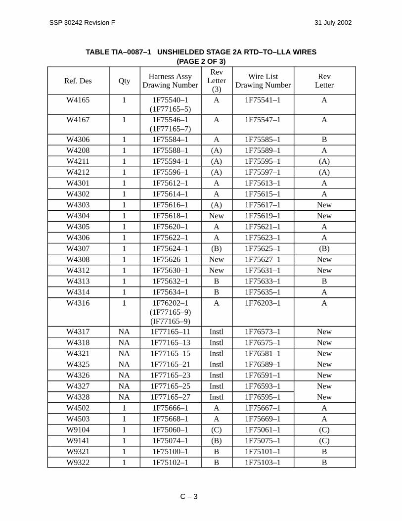
Exception: The unshielded Stage 2A RTD–to–LLA wires in the inboard truss cables complywith the intent of 3.2.1 and do not require braid shields. Affected cables are shown in TableC3.2.1.1–1.
TABLE TIA–0087–1 UNSHIELDED STAGE 2A RTD–TO–LLA WIRES(PAGE 1 OF 3)
Ref. Des Qty Harness AssyDrawing Number
RevLetter
(3)
Wire ListDrawing Number
RevLetter
W4107 1 1F75180–1 A 1F75181–1 AÁÁÁÁÁÁÁÁÁÁÁÁÁÁW4139
ÁÁÁÁÁÁÁÁ1
ÁÁÁÁÁÁÁÁÁÁÁÁÁÁ1F75514–1
ÁÁÁÁÁÁÁÁ(B)
ÁÁÁÁÁÁÁÁÁÁÁÁÁÁÁÁ1F75515–1
ÁÁÁÁÁÁÁÁÁÁÁÁÁÁNÁÁÁÁÁÁÁ
ÁÁÁÁÁÁÁW4154ÁÁÁÁÁÁÁÁ1
ÁÁÁÁÁÁÁÁÁÁÁÁÁÁ1F75342–1
ÁÁÁÁÁÁÁÁB
ÁÁÁÁÁÁÁÁÁÁÁÁÁÁÁÁ1F75343–1
ÁÁÁÁÁÁÁÁÁÁÁÁÁÁCÁÁÁÁÁÁÁ
ÁÁÁÁÁÁÁW4155ÁÁÁÁÁÁÁÁ1
ÁÁÁÁÁÁÁÁÁÁÁÁÁÁ1F75344–1
ÁÁÁÁÁÁÁÁ(C)
ÁÁÁÁÁÁÁÁÁÁÁÁÁÁÁÁ1F75345–1
ÁÁÁÁÁÁÁÁÁÁÁÁÁÁ(D)ÁÁÁÁÁÁÁ
ÁÁÁÁÁÁÁÁÁÁÁÁÁÁ
W4157ÁÁÁÁÁÁÁÁÁÁÁÁ
1ÁÁÁÁÁÁÁÁÁÁÁÁÁÁÁÁÁÁÁÁÁ
1F76506–1ÁÁÁÁÁÁÁÁÁÁÁÁ
AÁÁÁÁÁÁÁÁÁÁÁÁÁÁÁÁÁÁÁÁÁÁÁÁ
1F76507–1ÁÁÁÁÁÁÁÁÁÁÁÁÁÁÁÁÁÁÁÁÁ
B
ÁÁÁÁÁÁÁÁÁÁÁÁÁÁ
W4158 ÁÁÁÁÁÁÁÁ
1 ÁÁÁÁÁÁÁÁÁÁÁÁÁÁ
1F76508–1ÁÁÁÁÁÁÁÁ
A ÁÁÁÁÁÁÁÁÁÁÁÁÁÁÁÁ
1F76509–1 ÁÁÁÁÁÁÁÁÁÁÁÁÁÁ
B
ÁÁÁÁÁÁÁÁÁÁÁÁÁÁÁÁÁÁÁÁÁ
W4164 ÁÁÁÁÁÁÁÁÁÁÁÁ
1 ÁÁÁÁÁÁÁÁÁÁÁÁÁÁÁÁÁÁÁÁÁ
1F75538–1(1F77165–3)
ÁÁÁÁÁÁÁÁÁÁÁÁ
A ÁÁÁÁÁÁÁÁÁÁÁÁÁÁÁÁÁÁÁÁÁÁÁÁ
1F75539–1 ÁÁÁÁÁÁÁÁÁÁÁÁÁÁÁÁÁÁÁÁÁ
A
SSP 30242 Revision F 31 July 2002
C – 3
TABLE TIA–0087–1 UNSHIELDED STAGE 2A RTD–TO–LLA WIRES(PAGE 2 OF 3)
Ref. DesRev
LetterWire List
Drawing Number
RevLetter
(3)
Harness AssyDrawing NumberQty
ÁÁÁÁÁÁÁÁÁÁÁÁÁÁÁÁÁÁÁÁÁ
W4165 ÁÁÁÁÁÁÁÁÁÁÁÁ
1 ÁÁÁÁÁÁÁÁÁÁÁÁÁÁÁÁÁÁÁÁÁ
1F75540–1(1F77165–5)
ÁÁÁÁÁÁÁÁÁÁÁÁ
A ÁÁÁÁÁÁÁÁÁÁÁÁÁÁÁÁÁÁÁÁÁÁÁÁ
1F75541–1 ÁÁÁÁÁÁÁÁÁÁÁÁÁÁÁÁÁÁÁÁÁ
A
ÁÁÁÁÁÁÁÁÁÁÁÁÁÁÁÁÁÁÁÁÁ
W4167 ÁÁÁÁÁÁÁÁÁÁÁÁ
1 ÁÁÁÁÁÁÁÁÁÁÁÁÁÁÁÁÁÁÁÁÁ
1F75546–1(1F77165–7)
ÁÁÁÁÁÁÁÁÁÁÁÁ
A ÁÁÁÁÁÁÁÁÁÁÁÁÁÁÁÁÁÁÁÁÁÁÁÁ
1F75547–1 ÁÁÁÁÁÁÁÁÁÁÁÁÁÁÁÁÁÁÁÁÁ
A
ÁÁÁÁÁÁÁÁÁÁÁÁÁÁ
W4306 ÁÁÁÁÁÁÁÁ
1 ÁÁÁÁÁÁÁÁÁÁÁÁÁÁ
1F75584–1ÁÁÁÁÁÁÁÁ
A ÁÁÁÁÁÁÁÁÁÁÁÁÁÁÁÁ
1F75585–1 ÁÁÁÁÁÁÁÁÁÁÁÁÁÁ
BÁÁÁÁÁÁÁÁÁÁÁÁÁÁ
W4208 ÁÁÁÁÁÁÁÁ
1 ÁÁÁÁÁÁÁÁÁÁÁÁÁÁ
1F75588–1ÁÁÁÁÁÁÁÁ
(A)ÁÁÁÁÁÁÁÁÁÁÁÁÁÁÁÁ
1F75589–1 ÁÁÁÁÁÁÁÁÁÁÁÁÁÁ
AÁÁÁÁÁÁÁÁÁÁÁÁÁÁ
W4211 ÁÁÁÁÁÁÁÁ
1 ÁÁÁÁÁÁÁÁÁÁÁÁÁÁ
1F75594–1ÁÁÁÁÁÁÁÁ
(A)ÁÁÁÁÁÁÁÁÁÁÁÁÁÁÁÁ
1F75595–1 ÁÁÁÁÁÁÁÁÁÁÁÁÁÁ
(A)ÁÁÁÁÁÁÁÁÁÁÁÁÁÁ
W4212 ÁÁÁÁÁÁÁÁ
1 ÁÁÁÁÁÁÁÁÁÁÁÁÁÁ
1F75596–1ÁÁÁÁÁÁÁÁ
(A)ÁÁÁÁÁÁÁÁÁÁÁÁÁÁÁÁ
1F75597–1 ÁÁÁÁÁÁÁÁÁÁÁÁÁÁ
(A)ÁÁÁÁÁÁÁÁÁÁÁÁÁÁ
W4301 ÁÁÁÁÁÁÁÁ
1 ÁÁÁÁÁÁÁÁÁÁÁÁÁÁ
1F75612–1ÁÁÁÁÁÁÁÁ
A ÁÁÁÁÁÁÁÁÁÁÁÁÁÁÁÁ
1F75613–1 ÁÁÁÁÁÁÁÁÁÁÁÁÁÁ
AÁÁÁÁÁÁÁÁÁÁÁÁÁÁ
W4302ÁÁÁÁÁÁÁÁ
1ÁÁÁÁÁÁÁÁÁÁÁÁÁÁ
1F75614–1ÁÁÁÁÁÁÁÁ
AÁÁÁÁÁÁÁÁÁÁÁÁÁÁÁÁ
1F75615–1ÁÁÁÁÁÁÁÁÁÁÁÁÁÁ
AÁÁÁÁÁÁÁÁÁÁÁÁÁÁW4303
ÁÁÁÁÁÁÁÁ1
ÁÁÁÁÁÁÁÁÁÁÁÁÁÁ1F75616–1
ÁÁÁÁÁÁÁÁ(A)
ÁÁÁÁÁÁÁÁÁÁÁÁÁÁÁÁ1F75617–1
ÁÁÁÁÁÁÁÁÁÁÁÁÁÁNewÁÁÁÁÁÁÁ
ÁÁÁÁÁÁÁW4304ÁÁÁÁÁÁÁÁ1
ÁÁÁÁÁÁÁÁÁÁÁÁÁÁ1F75618–1
ÁÁÁÁÁÁÁÁNew
ÁÁÁÁÁÁÁÁÁÁÁÁÁÁÁÁ1F75619–1
ÁÁÁÁÁÁÁÁÁÁÁÁÁÁNewÁÁÁÁÁÁÁ
ÁÁÁÁÁÁÁW4305ÁÁÁÁÁÁÁÁ1
ÁÁÁÁÁÁÁÁÁÁÁÁÁÁ1F75620–1
ÁÁÁÁÁÁÁÁA
ÁÁÁÁÁÁÁÁÁÁÁÁÁÁÁÁ1F75621–1
ÁÁÁÁÁÁÁÁÁÁÁÁÁÁAÁÁÁÁÁÁÁ
ÁÁÁÁÁÁÁÁÁÁÁÁÁÁ
W4306ÁÁÁÁÁÁÁÁÁÁÁÁ
1ÁÁÁÁÁÁÁÁÁÁÁÁÁÁÁÁÁÁÁÁÁ
1F75622–1ÁÁÁÁÁÁÁÁÁÁÁÁ
AÁÁÁÁÁÁÁÁÁÁÁÁÁÁÁÁÁÁÁÁÁÁÁÁ
1F75623–1ÁÁÁÁÁÁÁÁÁÁÁÁÁÁÁÁÁÁÁÁÁ
A
ÁÁÁÁÁÁÁÁÁÁÁÁÁÁ
W4307 ÁÁÁÁÁÁÁÁ
1 ÁÁÁÁÁÁÁÁÁÁÁÁÁÁ
1F75624–1ÁÁÁÁÁÁÁÁ
(B)ÁÁÁÁÁÁÁÁÁÁÁÁÁÁÁÁ
1F75625–1 ÁÁÁÁÁÁÁÁÁÁÁÁÁÁ
(B)
ÁÁÁÁÁÁÁÁÁÁÁÁÁÁ
W4308 ÁÁÁÁÁÁÁÁ
1 ÁÁÁÁÁÁÁÁÁÁÁÁÁÁ
1F75626–1ÁÁÁÁÁÁÁÁ
NewÁÁÁÁÁÁÁÁÁÁÁÁÁÁÁÁ
1F75627–1 ÁÁÁÁÁÁÁÁÁÁÁÁÁÁ
NewÁÁÁÁÁÁÁÁÁÁÁÁÁÁ
W4312 ÁÁÁÁÁÁÁÁ
1 ÁÁÁÁÁÁÁÁÁÁÁÁÁÁ
1F75630–1ÁÁÁÁÁÁÁÁ
NewÁÁÁÁÁÁÁÁÁÁÁÁÁÁÁÁ
1F75631–1 ÁÁÁÁÁÁÁÁÁÁÁÁÁÁ
NewÁÁÁÁÁÁÁÁÁÁÁÁÁÁ
W4313 ÁÁÁÁÁÁÁÁ
1 ÁÁÁÁÁÁÁÁÁÁÁÁÁÁ
1F75632–1ÁÁÁÁÁÁÁÁ
B ÁÁÁÁÁÁÁÁÁÁÁÁÁÁÁÁ
1F75633–1 ÁÁÁÁÁÁÁÁÁÁÁÁÁÁ
BÁÁÁÁÁÁÁÁÁÁÁÁÁÁ
W4314 ÁÁÁÁÁÁÁÁ
1 ÁÁÁÁÁÁÁÁÁÁÁÁÁÁ
1F75634–1ÁÁÁÁÁÁÁÁ
B ÁÁÁÁÁÁÁÁÁÁÁÁÁÁÁÁ
1F75635–1 ÁÁÁÁÁÁÁÁÁÁÁÁÁÁ
AÁÁÁÁÁÁÁÁÁÁÁÁÁÁÁÁÁÁÁÁÁÁÁÁÁÁÁÁ
W4316 ÁÁÁÁÁÁÁÁÁÁÁÁÁÁÁÁ
1 ÁÁÁÁÁÁÁÁÁÁÁÁÁÁÁÁÁÁÁÁÁÁÁÁÁÁÁÁ
1F76202–1(1F77165–9)(IF77165–9)
ÁÁÁÁÁÁÁÁÁÁÁÁÁÁÁÁ
A ÁÁÁÁÁÁÁÁÁÁÁÁÁÁÁÁÁÁÁÁÁÁÁÁÁÁÁÁÁÁÁÁ
1F76203–1 ÁÁÁÁÁÁÁÁÁÁÁÁÁÁÁÁÁÁÁÁÁÁÁÁÁÁÁÁ
A
ÁÁÁÁÁÁÁÁÁÁÁÁÁÁ
W4317 ÁÁÁÁÁÁÁÁ
NAÁÁÁÁÁÁÁÁÁÁÁÁÁÁ
1F77165–11ÁÁÁÁÁÁÁÁ
InstlÁÁÁÁÁÁÁÁÁÁÁÁÁÁÁÁ
1F76573–1 ÁÁÁÁÁÁÁÁÁÁÁÁÁÁ
NewÁÁÁÁÁÁÁÁÁÁÁÁÁÁ
W4318 ÁÁÁÁÁÁÁÁ
NAÁÁÁÁÁÁÁÁÁÁÁÁÁÁ
1F77165–13ÁÁÁÁÁÁÁÁ
InstlÁÁÁÁÁÁÁÁÁÁÁÁÁÁÁÁ
1F76575–1 ÁÁÁÁÁÁÁÁÁÁÁÁÁÁ
NewÁÁÁÁÁÁÁÁÁÁÁÁÁÁ
W4321 ÁÁÁÁÁÁÁÁ
NAÁÁÁÁÁÁÁÁÁÁÁÁÁÁ
1F77165–15ÁÁÁÁÁÁÁÁ
InstlÁÁÁÁÁÁÁÁÁÁÁÁÁÁÁÁ
1F76581–1 ÁÁÁÁÁÁÁÁÁÁÁÁÁÁ
NewÁÁÁÁÁÁÁÁÁÁÁÁÁÁ
W4325 ÁÁÁÁÁÁÁÁ
NAÁÁÁÁÁÁÁÁÁÁÁÁÁÁ
1F77165–21ÁÁÁÁÁÁÁÁ
InstlÁÁÁÁÁÁÁÁÁÁÁÁÁÁÁÁ
1F76589–1 ÁÁÁÁÁÁÁÁÁÁÁÁÁÁ
NewÁÁÁÁÁÁÁÁÁÁÁÁÁÁ
W4326 ÁÁÁÁÁÁÁÁ
NAÁÁÁÁÁÁÁÁÁÁÁÁÁÁ
1F77165–23ÁÁÁÁÁÁÁÁ
InstlÁÁÁÁÁÁÁÁÁÁÁÁÁÁÁÁ
1F76591–1 ÁÁÁÁÁÁÁÁÁÁÁÁÁÁ
NewÁÁÁÁÁÁÁÁÁÁÁÁÁÁ
W4327ÁÁÁÁÁÁÁÁ
NAÁÁÁÁÁÁÁÁÁÁÁÁÁÁ
1F77165–25ÁÁÁÁÁÁÁÁ
InstlÁÁÁÁÁÁÁÁÁÁÁÁÁÁÁÁ
1F76593–1ÁÁÁÁÁÁÁÁÁÁÁÁÁÁ
NewÁÁÁÁÁÁÁÁÁÁÁÁÁÁW4328
ÁÁÁÁÁÁÁÁNA
ÁÁÁÁÁÁÁÁÁÁÁÁÁÁ1F77165–27
ÁÁÁÁÁÁÁÁInstl
ÁÁÁÁÁÁÁÁÁÁÁÁÁÁÁÁ1F76595–1
ÁÁÁÁÁÁÁÁÁÁÁÁÁÁNewÁÁÁÁÁÁÁ
ÁÁÁÁÁÁÁW4502ÁÁÁÁÁÁÁÁ1
ÁÁÁÁÁÁÁÁÁÁÁÁÁÁ1F75666–1
ÁÁÁÁÁÁÁÁA
ÁÁÁÁÁÁÁÁÁÁÁÁÁÁÁÁ1F75667–1
ÁÁÁÁÁÁÁÁÁÁÁÁÁÁAÁÁÁÁÁÁÁ
ÁÁÁÁÁÁÁW4503ÁÁÁÁÁÁÁÁ1
ÁÁÁÁÁÁÁÁÁÁÁÁÁÁ1F75668–1
ÁÁÁÁÁÁÁÁA
ÁÁÁÁÁÁÁÁÁÁÁÁÁÁÁÁ1F75669–1
ÁÁÁÁÁÁÁÁÁÁÁÁÁÁAÁÁÁÁÁÁÁ
ÁÁÁÁÁÁÁÁÁÁÁÁÁÁ
W9104ÁÁÁÁÁÁÁÁÁÁÁÁ
1ÁÁÁÁÁÁÁÁÁÁÁÁÁÁÁÁÁÁÁÁÁ
1F75060–1ÁÁÁÁÁÁÁÁÁÁÁÁ
(C)ÁÁÁÁÁÁÁÁÁÁÁÁÁÁÁÁÁÁÁÁÁÁÁÁ
1F75061–1ÁÁÁÁÁÁÁÁÁÁÁÁÁÁÁÁÁÁÁÁÁ
(C)
ÁÁÁÁÁÁÁÁÁÁÁÁÁÁ
W9141 ÁÁÁÁÁÁÁÁ
1 ÁÁÁÁÁÁÁÁÁÁÁÁÁÁ
1F75074–1ÁÁÁÁÁÁÁÁ
(B)ÁÁÁÁÁÁÁÁÁÁÁÁÁÁÁÁ
1F75075–1 ÁÁÁÁÁÁÁÁÁÁÁÁÁÁ
(C)
ÁÁÁÁÁÁÁÁÁÁÁÁÁÁ
W9321 ÁÁÁÁÁÁÁÁ
1 ÁÁÁÁÁÁÁÁÁÁÁÁÁÁ
1F75100–1ÁÁÁÁÁÁÁÁ
B ÁÁÁÁÁÁÁÁÁÁÁÁÁÁÁÁ
1F75101–1 ÁÁÁÁÁÁÁÁÁÁÁÁÁÁ
BÁÁÁÁÁÁÁÁÁÁÁÁÁÁ
W9322 ÁÁÁÁÁÁÁÁ
1 ÁÁÁÁÁÁÁÁÁÁÁÁÁÁ
1F75102–1ÁÁÁÁÁÁÁÁ
B ÁÁÁÁÁÁÁÁÁÁÁÁÁÁÁÁ
1F75103–1 ÁÁÁÁÁÁÁÁÁÁÁÁÁÁ
B

SSP 30242 Revision F 31 July 2002
C – 4
TABLE TIA–0087–1 UNSHIELDED STAGE 2A RTD–TO–LLA WIRES(PAGE 3 OF 3)
Ref. DesRev
LetterWire List
Drawing Number
RevLetter
(3)
Harness AssyDrawing NumberQty
ÁÁÁÁÁÁÁÁÁÁÁÁÁÁ
W9371 ÁÁÁÁÁÁÁÁ
NAÁÁÁÁÁÁÁÁÁÁÁÁÁÁ
1F75818–5ÁÁÁÁÁÁÁÁ
InstlÁÁÁÁÁÁÁÁÁÁÁÁÁÁÁÁ
1F75065–1 ÁÁÁÁÁÁÁÁÁÁÁÁÁÁ
NewÁÁÁÁÁÁÁÁÁÁÁÁÁÁ
W9372 ÁÁÁÁÁÁÁÁ
NAÁÁÁÁÁÁÁÁÁÁÁÁÁÁ
1F75817–5ÁÁÁÁÁÁÁÁ
InstlÁÁÁÁÁÁÁÁÁÁÁÁÁÁÁÁ
1F76451–1 ÁÁÁÁÁÁÁÁÁÁÁÁÁÁ
New
Rationale: The intent of the ML wire braid classification and the ensuing braid shields is toreduce EM interference.
Stage 2A designs sufficiently reduce RTD–to–LLA EM interferences of concern and thesedesigns were verified by the MDM qualification tests and a recent developmental test.
These designs and test results are summarized below.
Designs Sufficiently Reduce Common–Mode Interference:The RTD–to–LLA pairs contained within the in–board truss cables are co–bundled with multipleconductors which in effect shield the RTD–to–LLA pairs from external EM fields, reducing theircommon–mode interference to acceptable levels.
Designs Sufficiently Reduce Differential–Mode Interference: Several design features reduce differential–mode interference due to external EM fields onRTD–to–LLA pairs to acceptable levels.
First, the RTD–to–LLA pairs are twisted wires with the conductors in close proximity to oneanother which significantly reduces magnetically coupled interference. Second, they areterminated by balanced and ungrounded resistive loads on both sensor and signal conditionerends reducing differential–mode interference. Third, RTD–to–LLA transmission lines arebundled only with other signal–level transmission lines. Fourth, LLA signal conditioners arefiltered to respond to differential inputs of only a few tens of Hertz which further attenuatescoupled RF interference.
Designs Sufficiently Reduce Bundle Crosstalk:Several of the designs discussed above reduce bundle crosstalk. In addition, the LLA signalconditioner filters, passing differential inputs of only a few tens of Hertz, significantly reducefrequency–dependent bundle crosstalk.
These designs reduce bundle crosstalk to acceptable levels.
MDM Qualification Tests Verified Designs:Passed MDM RS03 qualification tests with the RTD–to–LAA pairs unshielded, as they areinstalled on Stage 2A.

SSP 30242 Revision F 31 July 2002
C – 5
Boeing - Huntington Beach Test Verified Designs:A recent developmental test, focusing on RTD–to–LLA interfaces, demonstrated RTD–to–LLAinterfaces are robust as installed.
This test was conducted during April 7–9, 1998, using flight–like wire harnesses interfacing withan MDM from Honeywell. The interfacing wire harnesses were configured in the screen room tosimulate their Stage 2A configuration. This included two loops. The effects of on–orbitelectromagnetic fields were simulated by simultaneously illuminating (radiating) both loops andthe MDM at the ISS RS03 specification levels, from 10 kHz to 15 GHz. No anomalies wereobserved. Thereafter, the illumination levels were increased to three times the specification levelfrom 10 kHz to 200 MHz, and twice the specification levels from 200 MHz to 1 GHz. Again, noanomalies were observed.
EMECB TIA–0113
C.3.2.2.2 IMPLEMENTATION OF CODING AND BUNDLING ANDC.3.2.2.3.2 SEPARATION REQUIREMENTS
Exception: The ECOMM GFE Project and Boeing – Houston are allowed to install cabling intoNode 1 that only partially meets the intent of 3.2.2.2 and 3.2.2.3.2, as depicted in SSP684–10276, “Early Communications System Interface Control Drawing,” Figure 10A, “CableLayout.” (Also see Boeing –HB Drawing 1F00308, “Patch Installation, Velcro – Node 1)
Rationale: Practical cable layout and runs in the Node, along with assembly–mission,early–ingress IVA considerations, and 2A flight crew preferences for cable bundling and routingpreclude the possibility of complete cabling separation into like functions and classifications.All of the cables are shielded and this provides the electromagnetic shielding required. Therewere no anomalies noted during KSC Cargo Element 2A Testing in this configuration (May18–20, 1998).
EMECB TIA–0122
C.3.2.1 CIRCUIT CLASSIFICATION
Exception: The unshielded PMA 3 RTD–to–MDM wires in the PMA 3 external wire harnessescomply with the intent of SSP–30242, paragraph 3.2.1, and do not require braid shields. Thewire harness part numbers involved in this agreement are: 1F92885, 1F92959, 1F92895,1F92891, 1F92897, 1F92893, 1F92899, 1F92901, 1F92903, 1F92905, 1F93312, and 1F93314.
Rationale: The intent of the ML wire braid classification and the ensuing braid shields is toreduce Electromagnetic (EM) interference. In TIA–087, the RTD was shown to be veryinsensitive to EM interferences. The RTD used on PMA 3 will be similarly insensitive to EMinterferences.
The PMA 3 designs sufficiently reduce RTD–to–MDM EM interferences of concern and thesedesigns were verified by the MDM qualification tests and a recent Stage 2A developmental test.

SSP 30242 Revision F 31 July 2002
C – 6
These designs and test results are summarized below:
Boeing–HB Designs Sufficiently Reduce Common–Mode Interference
The RTD–to–LLA pairs contained within the PMA 3 external wire harnesses are co–bundledwith multiple conductors which in effect shield the RTD–to–LLA pairs from external EM fields,reducing their common–mode interference to acceptable levels.
Boeing–HB Designs Sufficiently Reduce Differential–Mode Interference
Several design features reduce differential–mode interference due to external EM fields onRTD–to–LLA pairs to acceptable levels.
First, the RTD–to–LLA pairs are twisted wires with the conductors in close proximity to oneanother which significantly reduces magnetically coupled interference. Second, they areterminated by balanced and ungrounded resistive loads on both sensor and signal conditionerends reducing differential–mode interference. Third, RTD–to–LLA transmission lines arebundled only with other signal–level transmission lines. Fourth, LLA signal conditioners arefiltered to respond to differential inputs of only a few tens of Hertz which further attenuatescoupled RF interference.
Boeing–HB Designs Sufficiently Reduce Bundle Crosstalk
Several of the designs discussed above reduce bundle crosstalk. In addition, the LLA signalconditioner filters, passing differential inputs of only a few tens of Hertz, significantly reducefrequency–dependent bundle crosstalk.
These designs reduce bundle crosstalk to acceptable levels.
MDM Qualification Tests Verified Designs
Boeing–HB passed MDM RS03 qualification tests with the RTD–to–LAA pairs unshielded, asthey are installed on Stage 2A.
Boeing - Huntington Beach Test Verified Designs
A recent developmental test, focusing on RTD–to–LLA interfaces, demonstrated RTD–to–LAAinterfaces are robust as installed.
Boeing–HB conducted this test during April 7–9, 1998, using flight–like wire harnessesinterfacing with an MDM from Honeywell. Boeing–HB configured the interfacing wireharnesses in the screen room to simulate their Stage 2A configuration. This included two loops.Boeing–HB simulated the effects of on–orbit electromagnetic fields by simultaneouslyilluminating (radiating) both loops and the MDM at the ISS RS03 specification levels, from 10kHz to 15 GHz. Boeing–HB observed no anomalies. Thereafter, Boeing–HB increased theillumination levels to three times the specification level from 10 kHz to 200 MHz, and twice thespecification levels from 200 MHz to 1 GHz. Again, Boeing–HB observed no anomalies.

SSP 30242 Revision F 31 July 2002
C – 7
EMECB TIA–0125
C.3.2.1 CIRCUIT CLASSIFICATION
Exception: The unshielded Segment S1 (end item no. 222220A) RTD–to–Thermostat Box wiresin the in–board truss wire harnesses listed below comply with the intent of SSP–30242,paragraph 3.2.1, and do not require braid shields. The part numbers for the S1 wire harnessesare as follows: 1F80440, 1F80444, 1F82702, 1F82704, 1F82706, 1F82708, 1F82710, 1F82712,1F82714, 1F82716, 1F82718, 1F82720, 1F82722, 1F82724, 1F82726, 1F82728, 1F82730,1F82732, 1F82734, 1F82736, 1F82738, 1F82740, and 1F82742.
Rationale: The intent of the ML wire braid classification and the ensuing braid shields is toreduce EM interference. In TIA–087, the RTD was shown to be very insensitive to EMinterferences. The RTD used on Segment S1 (and later on Segment P1) will be similarlyinsensitive to EM interferences.
The Segment S1 designs sufficiently reduce RTD–to–Thermostat Box EM interferences ofconcern and these designs were verified by the MDM qualification tests and a recent Stage 2Adevelopmental test.
These designs and test results are summarized below:
Boeing–HB Designs Sufficiently Reduce Common–Mode Interference
The RTD–to–LLA pairs contained within the in–board truss cables are co–bundled with multipleconductors which in effect shield the RTD–to–LLA pairs from external EM fields, reducing theircommon–mode interference to acceptable levels.
Boeing–HB Designs Sufficiently Reduce Differential–Mode Interference
Several design features reduce differential–mode interference due to external EM fields onRTD–to–LLA pairs to acceptable levels.
First, the RTD–to–LLA pairs are twisted wires with the conductors in close proximity to oneanother which significantly reduces magnetically coupled interference. Second, they areterminated by balanced and ungrounded resistive loads on both sensor and signal conditionerends reducing differential–mode interference. Third, RTD–to–LLA transmission lines arebundled only with other signal–level transmission lines. Fourth, LLA signal conditioners arefiltered to respond to differential inputs of only a few tens of Hertz which further attenuatescoupled RF interference.
Boeing–HB Designs Sufficiently Reduce Bundle Crosstalk
Several of the designs discussed above reduce bundle crosstalk. In addition, the LLA signalconditioner filters, passing differential inputs of only a few tens of Hertz, significantly reducefrequency–dependent bundle crosstalk.
These designs reduce bundle crosstalk to acceptable levels.

SSP 30242 Revision F 31 July 2002
C – 8
MDM Qualification Tests Verified Designs
Boeing–HB passed MDM RS03 qualification tests with the RTD–to–LAA pairs unshielded, asthey are installed on Stage 2A.
Boeing – Huntington Beach Test Verified Designs
A recent developmental test, focusing on RTD–to–LLA interfaces, demonstrated RTD–to–LAAinterfaces are robust as installed.
Boeing–HB conducted this test during April 7–9, 1998, using flight–like wire harnessesinterfacing with an MDM from Honeywell. Boeing–HB configured the interfacing wireharnesses in the screen room to simulate their Stage 2A configuration. This included two loops.Boeing–HB simulated the effects of on–orbit electromagnetic fields by simultaneouslyilluminating (radiating) both loops and the MDM at the ISS RS03 specification levels, from 10kHz to 15 GHz. Boeing–HB observed no anomalies. Thereafter, Boeing–HB increased theillumination levels to three times the specification level from 10 kHz to 200 MHz, and twice thespecification levels from 200 MHz to 1 GHz. Again, Boeing–HB observed no anomalies.
EMECB TIA–126
C.3.2.1 CIRCUIT CLASSIFICATION
Exception: The unshielded Segment S0 (end item no. 222200A) RTD–to–MDM wires in thein–board truss cables listed below comply with the intent of SSP–30242, Space Station Wire andCable Design Requirements, paragraph 3.2.1 and do not require braid shields. The part numbersfor the SO wire harnesses are as follows: 1F75180, 1F75182, 1F75342, 1F75344, 1F75498,1F75514, 1F76506, 1F76508, 1F75538, 1F75540, 1F75546, 1F75584, 1F75588, 1F75594,1F75596, 1F75612, 1F75614, 1F75616, 1F75618, 1F75620, 1F75622, 1F75624, 1F75626,1F75630, 1F75632, 1F75634, 1F76202, 1F77165–9, 1F77165–11, 1F77165–13, 1F77165–15,1F77165–21, 1F77165–23, 1F77165–25, 1F77165–27, 1F75666, 1F75668, 1F75060, 1F75074,1F75100, 1F75102, 1F75818, and 1F75817.
Rationale: The intent of the ML wire braid classification and the ensuing braid shields is toreduce Electromagnetic (EM) interference. In TIA–087, the RTD was shown to be veryinsensitive to EM interferences. The RTD used on Segment S0 will be similarly insensitive toEM interferences.
The Segment S0 designs sufficiently reduce RTD–to–MDM EM interferences of concern andthese designs were verified by the MDM qualification tests and a recent Stage 2A developmentaltest.
These designs and test results are summarized below:
Boeing–HB Designs Sufficiently Reduce Common–Mode Interference

SSP 30242 Revision F 31 July 2002
C – 9
The RTD–to–LLA pairs contained within the in–board truss cables are co–bundled with multipleconductors which in effect shield the RTD–to–LLA pairs from external EM fields, reducing theircommon–mode interference to acceptable levels.
Boeing–HB Designs Sufficiently Reduce Differential–Mode Interference
Several design features reduce differential–mode interference due to external EM fields onRTD–to–LLA pairs to acceptable levels.
First, the RTD–to–LLA pairs are twisted wires with the conductors in close proximity to oneanother which significantly reduces magnetically coupled interference. Second, they areterminated by balanced and ungrounded resistive loads on both sensor and signal conditionerends reducing differential–mode interference. Third, RTD–to–LLA transmission lines arebundled only with other signal–level transmission lines. Fourth, LLA signal conditioners arefiltered to respond to differential inputs of only a few tens of Hertz which further attenuatescoupled RF interference.
Boeing–HB Designs Sufficiently Reduce Bundle Crosstalk
Several of the designs discussed above reduce bundle crosstalk. In addition, the LLA signalconditioner filters, passing differential inputs of only a few tens of Hertz, significantly reducefrequency–dependent bundle crosstalk.
These designs reduce bundle crosstalk to acceptable levels.
MDM Qualification Tests Verified Designs
Boeing–HB passed MDM RS03 qualification tests with the RTD–to–LAA pairs unshielded, asthey are installed on Stage 2A.
Boeing – Huntington Beach Test Verified Designs
A recent developmental test, focusing on RTD–to–LLA interfaces, demonstrated RTD–to–LAAinterfaces are robust as installed.
Boeing–HB conducted this test during April 7–9, 1998, using flight–like wire harnessesinterfacing with an MDM from Honeywell. Boeing–HB configured the interfacing wireharnesses in the screen room to simulate their Stage 2A configuration. This included two loops.Boeing–HB simulated the effects of on–orbit electromagnetic fields by simultaneouslyilluminating (radiating) both loops and the MDM at the ISS RS03 specification levels, from 10kHz to 15 GHz. Boeing–HB observed no anomalies. Thereafter, Boeing–HB increased theillumination levels to three times the specification level from 10 kHz to 200 MHz, and twice thespecification levels from 200 MHz to 1 GHz. Again, Boeing–HB observed no anomalies.

SSP 30242 Revision F 31 July 2002
C – 10
EMEP TIA–0180
C.3.2.2.1.3 SHIELD GROUNDING REQUIREMENTS
Exemption: The Node 2 cable harnesses Harness Manufacturing Units (PNs 602, 603, 612, 613,623, 633, 636, 722, 724) are exempted from meeting the 3.2.2.1.3 shield grounding requirementsby grounding their shields through connector pins and not to the connector backshells at breakpoints.
Rationale: The 3.2.2.1.3 Shield Grounding Requirements states “Shields shall be terminated atboth ends and at intermediate break points directly to structure or chassis, through connectorbackshells or direct wire connection…” Alenia interpreted direct wire connection to meantermination to pins at intermediate break points was acceptable. Additionally, Alenia’s designpractice of termination of shields to pins at production breaks facilitates troubleshooting of theharness should it become necessary. The cable harness design and procurement are underAlenia’s control and not United States On–orbit Segment. The termination of the shields to pinsinstead of backshells for these cable harnesses does not represent a problem because they are notcritical circuits.
EMEP TIA–0221
C.3.2.1 CIRCUIT CLASSIFICATION
Exception: The unshielded United States Laboratory (USL) (CI# 683400A) and Airlock (CI#683C01A) RTD–to–MDM interface cables and pigtails comply with the intent of 3.2.1 and donot require braid shields. The part numbers for the wire harnesses are as follows:USL: 683–20193, 683–22044, 683–22045, 683–22046, 683–22047, 683–22048, 683–22049,683–22053, 683–22054, 683–22055, 683–22056, 683–22021, 683–22022, 683–22023,683–22024, 683–22025, 683–22026, and Heat Exchanger wire harness 1F70130.Airlock: 683–52086, 683–52031, and 683–52019.
Rationale: The intent of the ML wire braid classification and the ensuing braid shields is toreduce EM interference. In TIA–0126, the RTD was shown to be very insensitive to EMinterference. The RTD wiring used on the USL and Airlock Modules will be similarlyinsensitive to the effects of electromagnetic coupling.
The USL and Airlock cable configurations sufficiently reduce RTD–to–MDM EM coupledinterference; these designs were verified by the MDM qualification tests and a recent Stage 2Adevelopmental test. The Thermostat RTD RF response to the effects of electromagnetic couplingcan be considered similar or more benign to that of the MDM LLA response.
These designs and test results are summarized below:
A. Boeing–HB/Huntsville Designs Sufficiently Reduce Common–Mode Interference
The RTD–to–LLA and Thermostat pairs contained within the USL interface cables areco–bundled with multiple conductors which in effect shield the RTD pairs from external EMfields, reducing their common–mode interference to acceptable levels.

SSP 30242 Revision F 31 July 2002
C – 11
Most of the RTDs in the USL have shielded wire leads; all the RTDs in the USL connecting to aMDM have shielded wires. In the Airlock many of the RTDs had twisted wire unshieldedpigtails which were connected to a shielded cable as soon as practical in the cabling design. Forthe wall heaters in both modules, the thermostat leads to the RTDs had shields and were run asfar as feasible before dead–ending the shields and connecting the thermostat wires to the twistedwire pigtails of the RTDs.
The internal cabling is shielded from the external RF environment by the module structure andwalls. The external wall heaters (Launch–to–Activation heaters) are shielded by the metal layersin the Meteoroid and Debris Shield and the metalized layers in the Multilayer Insulationblankets.
B. Boeing–HB/Huntsville Designs Sufficiently Reduce Differential Mode Interference
Several design features reduce differential mode interference due to external electromagneticfields on RTD to LLA and Thermostat pairs to acceptable levels.
First, the RTD pairs are twisted wires with the conductors in close proximity to one another,which significantly reduces magnetically coupled interference. Second, they are terminated bybalanced and ungrounded resistive loads on both sensor and signal conditioner ends reducingdifferential mode interference. Third, RTD transmission lines are bundled only with othersignal–level transmission lines. Fourth, LLA signal conditioners are filtered to respond todifferential inputs of only a few tens of Hertz, which further attenuates coupled RF interference.
C. Boeing–HB/Huntsville Designs Sufficiently Reduce Bundle Crosstalk
Several of the designs discussed above reduce bundle crosstalk. In addition, the LLA signalconditioner filters, passing differential inputs of only a few tens of Hertz, significantly reducefrequency dependent bundle crosstalk.
These designs reduce bundle crosstalk to acceptable levels.
D. MDM Qualification Tests Verified Designs
Boeing–HB passed MDM RS03 qualification tests with the RTD to LLA pairs unshielded, asthey are installed on Stage 2A.
E. Boeing–Huntington Beach Test Verified Designs
A recent developmental test, focusing on RTD to LLA interfaces, demonstrated RTD to LAAinterfaces are robust as installed.

SSP 30242 Revision F 31 July 2002
C – 12
Boeing–HB conducted this test during April 7–9, 1998, using flight–like wire harnessesinterfacing with an MDM from Honeywell. Boeing–HB configured the interfacing wireharnesses in the screen room to simulate their Stage 2A configuration. This included two loops.Boeing–HB simulated the effects of on orbit electromagnetic fields by simultaneouslyilluminating (radiating) both loops and the MDM at the ISS RS03 specification levels, from 10kHz to 15 GHz. Boeing–HB observed no anomalies. Thereafter, Boeing–HB increased theillumination levels to three times the specification level from 10 kHz to 200 MHz, and twice thespecification levels from 200 MHz to 1 GHz. Again, Boeing–HB observed no anomalies.
EMEP TIA–0341
C.3.2.1 CIRCUIT CLASSIFICATION
Exception: The unshielded Cupola (CI 684EA2A, PN CP2102F) RTD to MDM wires in theCupola wire harnesses comply with the intent of 3.2.1 and do not require braid shields.
Rationale: The intent of the ML wire braid classification and the ensuing braid shields is toreduce Electromagnetic Interference (EMI). In TIA–087 and TIA–122, the RTD to LLAinterface was shown to be very insensitive to EMI. Cupola harness is interfacing with Node1and PMA1 harnesses (Cupola RTD harness N1–WB0308) for which TIA–066 has already beenaccepted.
The Cupola design sufficiently reduces RTD to MDM EMI concerns and this design was verifiedby the MDM qualification tests. The design and test results are summarized below:
The Cupola design sufficiently reduces differential and common mode interferences.The RTD to LLA 4–wires connection contained within the Cupola wire harnesses is cobundledwith other RTD to LLA 4–wires conductors which in affect shield the RTD to LLA interfacefrom electromagnetic fields, reducing the common mode interference to acceptable levels.
Several Cupola design features reduce differential mode interference due to externalelectromagnetic fields on RTD to LLA pairs to acceptable levels. First, the RTD to LLA 4–wiresare made using two cables (with two twisted wires each) with the conductors in close proximityto one another. This significantly reduces magnetically coupled interference. Second, voltagemeasurement and excitation transmission lines are shorted together at the RTD. Bundlingtogether excitation and voltage measurement transmission lines minimizes the loop whichsignificantly reduces magnetically coupled interference. Third, the RTD to LLA 4–wires areterminated by balanced and ungrounded resistive loads on both sensor and signal conditionerends reducing common mode interference. Fourth, RTD to LLA transmission lines are bundledonly with other RTD to LLA transmission lines. Fifth, LLA signal conditioners are filtered torespond to differential inputs of less than 50 Hertz, which further attenuates coupled RFinterference. Sixth, the Cupola RTD harness cables are running between the primary and thealuminum made secondary structure (close to the primary structure at about 0.2 cm of distance).Only about 10 cm of these cables are not shielded by the secondary structure and are directlyexposed to the Cupola cabin field (the part of the cables approaching the window connectors).

SSP 30242 Revision F 31 July 2002
C – 13
The Cupola design sufficiently reduces bundle crosstalk. Several of the design featuresdiscussed above reduce bundle crosstalk. In addition, the LLA signal conditioner filters, passingdifferential inputs of less than 50 Hertz, significantly reduce frequency dependent bundlecrosstalk. This reduces bundle crosstalk to acceptable levels.
The MDM qualification tests verified the design. The MDM passed RS03 qualification testswith the RTD to LAA pairs unshielded as they are installed on Stage 2A.
The Node 1 harness interfacing with the Cupola RTD harness is currently classified and designedas HO. The Node 3 harness interfacing with the Cupola RTD harness is currently classified anddesigned as HO for the “Excitation” signals and ML for the “Voltage Measurement” signals.
EMEP TIA–0404
C3.2.1 CIRCUIT CLASSIFICATION
Exception: The unshielded ITS P3 (CI# 222280A) and ITS S3 (CI# 222240A) remote terminaldevice to Space Station MDM wires in the in board truss wire harnesses listed below complywith the intent of 3.2.1 and do not require braid shields.
The part numbers for the ITS P3 wire harnesses are 1F84072, 1F84074, 1F83076, 1F83078,1F84110, 1F84112, 1F84106, 1F54102, 1F84140, 1F84120, 1F84130, 1F97381, and 1F97332.
The part numbers for the ITS S3 wire harnesses are 1F84072, 1F84074, 1F86076, 1F86078,1F86110, 1F86112, 1F86102, 1F86102, 1F86120, 1F86130, 1F97349, and 1F97336.
Rationale: The intent of the circuit class ML wire braid classification and the braid shields is toreduce EMI. In EMEP TIA–087, the remote terminal device was shown to be very insensitive toEMI. The remote terminal device used on ITS P3 and ITS S3 was similarly insensitive to EMI.
The ITS P3 design reduces the remote terminal device to SSMDM LLA EMI concern and thedesign was verified by the MDM qualification tests, a Stage 2A developmental test, and thesuccessful flight experience with Stage 2A that has been in orbit for nearly two years.
The Boeing–Huntington Beach (HB) design reduces Common Mode Interference. The RTD toLLA pairs contained within the inboard truss cables are cobundled with multiple conductors thatshield the RTD to LLA pairs from external electromagnetic fields reducing their common modeinterference to acceptable levels.
The Boeing–HB design reduces differential mode interference. Several design features reducedifferential mode interference due to external electromagnetic fields on remote terminal deviceto LLA pairs to acceptable levels. First, the remote terminal device to LLA pairs are twistedwires with the conductors in close proximity to one another, which significantly reducesmagnetically coupled interference. Second, the pairs are terminated by balanced andungrounded resistive loads on both sensor and signal conditioner ends reducing differential modeinterference. Third, remote terminal device to LLA transmission lines are bundled only withother signal level transmission lines. Fourth, LLA signal conditioners are filtered to respond todifferential inputs of only a few tenths of hertz that attenuates coupled RF interference.

SSP 30242 Revision F 31 July 2002
C – 14
The Boeing–HB design reduces bundle crosstalk. The LLA signal conditioner filters, passingdifferential inputs of only a few tens of hertz, which reduces frequency dependent bundlecrosstalk to acceptable levels.
The Boeing–HB design passed the MDM RS03 qualification tests with the RTD to LLA pairsunshielded, as they are installed on Stage 2A.
A developmental test, focusing on remote terminal device to LLA interfaces, demonstrated thatthe remote terminal device to LLA interfaces are robust as installed. Boeing–HB conducted thistest April 7–9, 1998, using flight like wire harnesses interfacing with a MDM from Honeywell.Boeing–HB configured the interfacing wire harnesses in the screen room to simulate the Stage2A configuration. This included two loops. Boeing–HB simulated the effects of on–orbitelectromagnetic fields by simultaneously illuminating (radiating) both loops and the MDM at theISS RS03 levels, from 10 kHz to 15 GHz. No anomalies were observed. Boeing–HB increasedthe illumination levels to three times the specification level from 10 kHz to 200 MHz, and twicethe specification levels from 200 MHz to 1 GHz. No anomalies were observed.
Stage 2A (Node 1 and Pressurized Mating Adapters) has been in orbit since December 1999.The Stage 2A remote terminal device to MDM LLA twisted pair cables have proven to beimmune to on–orbit radiation field to cable coupling interference without additional shielding.