software development plan for the human research...
TRANSCRIPT

Software Development Plan
for the Human Research Facility
CCB CONTROLLED
National Aeronautics and Space Administration
Lyndon B. Johnson Space CenterHouston, Texas 77058
LS-71020B
January 2001Rev. B
Change B-3

PROJECT DOCUMENT APPROVAL SHEET
DOCUMENT NUMBER DATE NO. OF LS-71020B 1/11/01 PAGES 110
TITLE:
Software Development Plan for the
Human Research Facility
APPROVED: NT3/GFE Assurance Branch Original Signature on File 1-3-01
APPROVED: SF4/C. Haven Configuration Control Manager Original Signature on File 1/5/01
APPROVED: SF2/D. Grounds HRF Program Manager Original Signature on File 1/11/01
DATE PREPARED BY CHANGE APPROVALS CHANGE NUMBER
6/28/01
10/1/01
02/05/04
M. Klee M. Klee M. Klee
Reference CCBD: HLP1-D020&020-1-0001 Reference CCBD: HLP1-D020&002 Reference CCBD: HLP1-D020-005-0001
B-1 B-2 B-3
JSC FORM 604 (REV JUL 81) NASA-JSC

Report Number LS-71020B Date 12/05/00
Software Development Plan for the
Human Research Facility
Prepared by: Original Signature on File Margaret Klee Software Development Project Manager
11/22/00 Date
Approved: Original Signature on File Mark Scott HRF Software Quality Assurance
12/04/00 Date
Approved: Original Signature on File Gloria Salinas Technical Work Plan Manager
12/15/00 Date
Prepared by:
Lockheed Martin Space Operations Houston, Texas
For National Aeronautics and Space Administration
Johnson Space Center
REVISION/CHANGE APPROVALS
Revision Change Approved by: Date Letter Number Prepared by
Unit Manager SR&QA Manager Projects Manager
6/28/01 B-1 M. Klee Reference: CCBD:HLP1-D020&020-1-0001
10/1/01 B-2 M. Klee Reference: CCBD:HLP1-D020-0002
02/05/04 B-3 M. Klee Reference: CCBD:HLP1-D020-0005-0001
Lockheed Martin Space Operations (March 1999)

DOCUMENT NUMBER DOCUMENT CHANGE/ PAGE 1 OF 1 LS-71020B REVISION LOG
CHANGE/ REVISION DATE DESCRIPTION OF CHANGE PAGES
AFFECTED
Basic 12/17/97 Baseline Issue
1 4/3//98 Update to correct documentation references, minor process improvements and document corrections – Reference CCBD: HPP1-D020-0052
V, 1-1.5-9, 5-10, A-24, A-25, A-28, A-29
2 10/1/98 Configuration Control Board Directive HJP1-D020-0012 was prepared to officially baseline this document
Cover, Document Change/Revision Log
A 12/113/99 Complete Revision. See CCBD: HJ00-D020-0002 All
B 1/11/01 Complete Revision. See CCBD: HJ00-D020-0003 All
B-1 6/28/01 Updated Section 4.1 Software Process Overview; Section 5.5 CSCI Integration and Testing; Section 5.6 System Integration Testing; Section 5.8 Preparing Software for Use; Section 8.0 Notes; and Appendix A3.0. Added Appendix D and Appendix E.
Contents, 4-1, 4-5,5-7,508, 5-11, 8-1, A-26, A-31, and A-35. Add Appendix D and Appendix E.
B-2 10/1/01 Updated Appendix A, Appendix D, and Appendix E per CCBD: HLP1-D20-0002.
A-4 through A-8, A-34 through A-36, D-4, E-1 through E-4-6
B-3 02/05/04 Updated the Acronyms, Contents for the Appendix, Acronyms, Section 2.0 Reference Documents, Section 5.9.5 Storage, Handling and Delivery of Project Software, and Appendix A. Added Appendix F and Appendix G - Referenced CCBD: HLP1-D020-005-0001.
v, vi, Appendix i through Appendix iii, 2-1, 5-12, A-38, A-39, F-1 through F-6, G-1 through G-3.
Altered pages must be typed and distributed for insertion. JSC Form 278 (rev APR 81) nasa-jsc

LS-71020B-11/21/00 i
CONTENTS
Section Page 1.0 SCOPE 1-1 1.1 IDENTIFICATION 1-1 1.2 SYSTEM OVERVIEW 1-1 1.3 DOCUMENT OVERVIEW 1-2 2.0 REFERENCED DOCUMENTS 2-1 3.0 DEFINITION AND ASSUMPTIONS 3-1 3.1 TYPES OF SOFTWARE 3-1 3.1.1 Flight Software 3-1 3.1.2 Ground Support Software 3-1 3.1.3 Test and Simulation Software 3-1 3.2 SOFTWARE CATEGORIES 3-1 3.2.1 HRF Unique Software 3-1 3.2.2 Non-Developmental Software 3-2 3.3 REQUIREMENT DOCUMENTATION 3-3 3.4 CONFIGURATION ITEMS 3-4 3.4.1 Computer Software Configuration Item 3-4 3.4.2 Computer Software Unit 3-4 3.5 ROLES AND RESPONSIBILITIES 3-4 3.6 ASSUMPTIONS 3-4 4.0 SOFTWARE DEVELOPMENT PROCESS 4-1 4.1 SOFTWARE PROCESS OVERVIEW 4-1 4.2 SOFTWARE DEVELOPMENT METHODS 4-5 4.3 STANDARDS FOR SOFTWARE PRODUCTS 4-7 4.4 HANDLING CRITICAL REQUIREMENTS 4-8 4.5 RECORDING RATIONALE 4-8 5.0 SOFTWARE DEVELOPMENT ACTIVITIES 5-1 5.1 ESTABLISHING A SOFTWARE DEVELOPMENT ENVIRONMENT 5-1 5.1.1 Software Engineering Environment 5-1 5.1.2 Software Test Environment 5-1 5.1.3 Software Configuration Library 5-1 5.1.4 Firmware Management 5-1 5.1.5 Software Development Files 5-2 5.2 SYSTEM REQUIREMENTS ANALYSIS AND SYSTEM DESIGN 5-2

LS-71020B-11/21/00 ii
CONTENTS (Cont'd)
Section Page 5.3 SOFTWARE DESIGN 5-3 5.3.1 Software Requirements and Preliminary Design (Flight Software Only) 5-3 5.3.2 Software Detailed Design 5-5 5.4 SOFTWARE IMPLEMENTATION AND UNIT TESTING 5-6 5.5 CSCI INTEGRATION AND TESTING 5-7 5.6 SYSTEM INTEGRATION TESTING 5-8 5.7 CSCI QUALIFICATION TESTING (FLIGHT SOFTWARE ONLY) 5-9 5.8 PREPARING SOFTWARE FOR USE 5-11 5.9 SOFTWARE CONFIGURATION MANAGEMENT 5-11 5.9.1 Configuration Identification 5-12 5.9.2 Configuration Control 5-12 5.9.3 Configuration Status Accounting 5-12 5.9.4 Configuration Audits 5-12 5.9.5 Storage, Handling and Delivery of Project Software 5-12 5.10 SOFTWARE QUALITY ASSURANCE 5-13 5.11 CORRECTIVE ACTION 5-13 5.11.1 Problem/Change Reports 5-13 5.11.2 Corrective Action System 5-13 5.12 REVIEWS 5-13 5.13 RISK MANAGEMENT 5-14 5.14 SECURITY AND PRIVACY 5-14 5.15 SUBCONTRACTOR MANAGEMENT 5-14 5.16 PROCESS IMPROVEMENT 5-14 6.0 SCHEDULES 6-1 7.0 PROJECT ORGANIZATION AND RESOURCES 7-1 8.0 NOTES 8-1 APPENDIX A DOCUMENT TEMPLATES A-1 APPENDIX B REVIEW CHECKLISTS B-1 APPENDIX C HRF CODING STYLE GUIDE C-1 APPENDIX D HRF SOFTWARE TESTING GUIDELINES D-1 APPENDIX E HRF MEDIA PART NUMBERS AND LABELING GUIDELINES E-1

LS-71020B-11/21/00 iii
LIST OF TABLES
Table Page 3.5-1 HRF SOFTWARE DEVELOPMENT ROLES AND RESPONSIBILITIES 3-5 4.1-1 LIFECYCLE PHASE VERSES SOFTWARE TYPE AND CATEGORY 4-4 5.2-1 SUMMARY OF SYSTEM REQUIREMENTS ANALYSIS AND
SYSTEM DESIGN 5-3 5.3.1-1 SUMMARY OF SOFTWARE REQUIREMENTS AND PRELIMINARY
DESIGN 5-4 5.3.2-1 SUMMARY OF SOFTWARE DETAILED DESIGN 5-6 5.4-1 SUMMARY OF SOFTWARE IMPLEMENTATION AND UNIT
TESTING 5-7 5.5-1 SUMMARY OF CSCI INTEGRATION AND TESTING 5-8 5.6-1 SUMMARY OF SYSTEM INTEGRATION TESTING 5-9 5.7-1 SUMMARY OF CSCI QUALIFICATION TESTING 5-10

LS-71020B-11/21/00 iv
LIST OF FIGURES
Figure Page 4.1-1 HRF Software Development Process for Flight Software 4-2 4.1-2 HRF Software Development Process for Ground Support, Test and
Simulation, Software 4-3 4.1-3 HRF Software Change Process 4-6

LS-71020B-02/03/04 v
B-3
B-3
B-3
B-3
B-3
B-3
B-3
ACRONYMS AND ABBREVIATIONS
ADP Acceptance Data Package CCB Configuration Control Board CD Compact Disc CDR Critical Design Review CHeCS Crew Health Care System CI Configuration Item CM Configuration Management CMS Configuration Management System COTS Commercial Off-The-Shelf CPU Central Processing Unit CQT CSCI Qualification Testing CR Change Request CSCI Computer Software Configuration Item CSU Computer Software Unit DBMS Database Management System DR Discrepancy Report EPI Engineering Process Improvement EPROM Erasable Programmable Read Only Memory EXPRESS EXpedite the PRocessing of Experiments to Space Station FRD Functional Requirements Document FTP File Transfer Protocol GCAR Government Certification Acceptance Report GSS Ground Support Software GUI Graphical User Interface HCI Human-Computer Interface HDP Hardware Development Plan HRD Hardware Requirements Document HRF Human Research Facility ICD Interface Control Document IDD Interface Definition Document IEEE Institute of Electrical and Electronics Engineers IP International Partner ISS International Space Station JSC Johnson Space Center KSC Kennedy Space Center LMSO Lockheed Martin Space Operations MB Megabytes MDM Multiplexer/Demultiplexer MOTS Modified COTS

LS-71020B-02/03/04 vi
B-3
B-3
B-3
B-3
B-3
B-3
B-3
B-3
ACRONYMS AND ABBREVIATIONS (Cont’d)
MPLM Mini Pressurized Logistics Module MRB Material Review Board MSFC Marshall Space Flight Center NASA National Aeronautics and Space Administration NDS Non-Developmental Software OCA Orbiter Communication Adapter OCR Operations Change Request PAR Payload Anomaly Report PC Portable Computer PCM Program Change Memo PCMCIA Portable Computer Memory Card International Adapter PI Principal Investigator PIMS Payload Information Management System POIC Payload Operation and Integration Center PRD Program Requirements Document PROM Programmable Read Only Memory PSE Payload System Engineer RIC Rack Interface Controller RICO Real-time Information Control Officer ROM Read Only Memory RTM Requirements Traceability Matrix SDD Software Design Document SDF Software Development File SDP Software Development Plan SIT System Integration Testing SQA Software Quality Assurance TDIC Technical Documentation and Information Center TPS Task Performance Sheet TSC Telescience Support Center VDD Version Description Document/Drawing

LS-71020B-11/20/00 1-1
1.0 SCOPE
1.1 IDENTIFICATION The Software Development Plan (SDP) for the Human Research Facility (HRF) establishes the programmatic requirements, policies, procedures and guidelines for software development, testing and sustaining engineering in addition to those requirements set forth in the Program Requirements Document (PRD) for the HRF (LS-71000). The following types of software will be either developed or acquired for the HRF to fulfill the Functional Requirements Document (FRD) for the HRF (LS-71001) and PRD specifications: a) Flight Software
b) Ground Support Software (GSS)
c) Test and Simulation Software This SDP establishes the policies, procedures and guidelines for development, testing and sustaining engineering of software developed for HRF experiments. The SDP document templates illustrate how requirements traceability from the Hardware Requirements Document (HRD) to the HRF Software Requirement and implementing computer software configuration item (CSCI) is managed. Configuration Management policies and procedures for HRF software are documented in the Software Configuration Management Plan and Procedures for the HRF (LS-71020-1). The Display and Graphics Commonality Standard (SSP 50313) and the Human-Computer Interface (HCI) Design Guide (LS-71130) shall be referenced for all user interfaces and display software development.
1.2 SYSTEM OVERVIEW The HRF is a facility class payload that consists of a suite of generic human life sciences hardware needed to support a multidisciplinary research program that encompasses basic, applied, and operations research. The HRF will include equipment to support research to understand the effects of weightlessness and the space environment on human systems and to develop, where appropriate, methods to counteract these effects for ensuring safe and efficient crew operations. Basic research and clinical investigations from both the intramural and extramural communities, as well as investigations from other federal agencies and the international community, will all be conducted using the HRF. All hardware/system elements to be used during the conduct of human research on the International Space Station (ISS) may not necessarily be included in the HRF racks. The ability to conduct thorough, multidisciplinary investigations will depend on the interaction of the HRF with the ISS systems, the Crew Health Care System (CHeCS) program, and other hardware provided by the international partners. In addition, the HRF subsystems and experiment packages will be modular in design so that the HRF can be configured to meet many sets of research objectives for the duration of the ISS program. The HRF will be developed in multiple phases, or launch packages. Each launch package is comprised of science instruments or integrated experiments. This

LS-71020B-11/20/00 1-2
equipment is installed in a customized EXpedite the PRocessing of Experiments to Space Station (EXPRESS) rack or stowed in stowage trays or drawers external to the integrated rack. Each launch package is designed such that the entire complement of equipment can be manifested for flight to orbit in a Mini Pressurized Logistics Module (MPLM) with some elements installed in the mid-deck of the Space Shuttle. Final integration of the launch packages will occur on-orbit.
1.3 DOCUMENT OVERVIEW The HRF SDP contains the requirements of the software development process, requirements for implementing the process, and templates for the software document products identified. The SDP contents and templates are based on information contained in Institute of Electrical and Electronics Engineers (IEEE) 1498 and the methods presented in the Standards and Practices Manual for Software Engineering. In addition, this document complies with the Lockheed Martin Quality System Manual (QSM) and Quality System Procedure (QSPs), which embody the International Standards Organization (ISO) 9000-series requirements. Document templates are located in Appendix A. Process checklists are located in Appendix B.

LS-71020B-02/03/04 2-1
2.0 REFERENCED DOCUMENTS Document No. Rev. Document Title
IEEE-1498 Draft 2 Standard for Information Technology, Software Life-Cycle Processes, Software Development, Acquirer-Supplier Agreement
JPD 5335.1 A Lyndon B. Johnson Space Center Quality Manual
JSCM 2410.11 Baseline JSC Automated Information Systems (AIS) Security Manual
LMSEAT-31474 See Web Standards and Practices Manual for Software Engineering (Website: https://www.hop.hou.lmsg.lmco.com/seat/prog_ only/dept/s20/iso9001/SoftEngr/Frame.htm NOTE: Access to this document requires access to
the LMSO internal network.
LS-71000 A Program Requirements Document for the Human Research Facility
LS-71001 A Functional Requirements Document for the Human Research Facility
LS-71005 A Configuration Management Plan for the Human Research Facility
LS-71020-1 A Software Configuration Management Plan and Procedure for the Human Research Facility
LS-71130 Baseline Human-Computer Interface (HCI) Design Guide for the Human Research Facility (HRF)
LS-71147-3 Check with TDIC for most recent version
HRF Rack Integration Test Procedure: Software Integration Procedure
MIL-STD-100 E Engineering Drawing Practices
NASA-STD-8719.13A
Software Safety NASA Technical Standard
SSP 50313 See Web Display and Graphics Commonality Standard (website: flight.jsc.nasa.gov/IDAGS/dgcs.html)
B-3
B-3

LS-71020B-11/20/00 3-1
3.0 DEFINITION AND ASSUMPTIONS
3.1 TYPES OF SOFTWARE
3.1.1 Flight Software Flight software is the software that will be installed on the flight articles and will be used on-orbit. Software written for experiments and that will be used on-orbit is considered flight software.
3.1.2 Ground Support Software GSS is the software used to test and/or verify flight hardware and/or flight software. GSS must be tested to the same standards as flight software. Specific process waivers for GSS and identified in Section 5.
3.1.3 Test and Simulation Software Test software and simulations will provide the environment for the integration and verification of the HRF flight software and avionics from software development through integration. This will involve the test environment with End-Item and segment simulations; environmental simulations which represent the HRF on-orbit environment and dynamics; and, sensor/effector simulations. Some simulations will be reused in verification activities at multiple facilities (i.e., End-Item, Stage, and Launch Package). HRF personnel will select the appropriate type of test software to support CSCI testing.
3.2 SOFTWARE CATEGORIES There are two general categories of software: HRF Unique software and Non-Developmental Software (NDS). The following sections further specify these general categories.
3.2.1 HRF Unique Software HRF unique software consists of all software written by HRF personnel specifically for HRF. There are four types of HRF unique software: a) Custom-build Software
b) Modified Commercial Off-The-Shelf (COTS) Software
c) Modified Government Furnished Software (GFS)
d) Data and Configuration Files
3.2.1.1 Custom-Build Software Custom-build software is software written by HRF personnel based on requirements defined in a requirements document to meet specifications in the FRD, PRD or other source.

LS-71020B-11/20/00 3-2
3.2.1.2 Modified COTS (MOTS) Software MOTS software is COTS software that must be customized for HRF use. All modified portions of the COTS software must comply with the same development and documentation standards and procedures as custom-build software. Supplier documentation can be included in HRF documents by reference. Prior to modification, all COTS software shall be inspected for completeness of programs and documentation, and undergo testing to ensure the absence of software viruses. Completion of this routine check-in procedure shall be documented in the Software Development File (SDF) of the affected CSCI.
3.2.1.3 Modified GFS Modified GFS is GFS that must be customized for HRF use. All modified portions of the GFS software must comply with the same development and documentation standards and procedures as custom-build software. Supplier documentation can be included in HRF documents by reference. Prior to modification, GFS shall be inspected for completeness of programs and documentation, and undergo testing to ensure the absence of software viruses. Completion of this routine check-in procedure shall be documented in the SDF of the affected CSCI.
3.2.1.4 Data and Configuration Files Data and configuration files are those files generated to provide initial data of configuration to a program or the system. These files are text files, but some may contain binary information. Data and configuration files shall be treated the same as the software they support. For instance, flight data and configuration files will be documented and tested to the same level as flight software.
3.2.2 Non-Developmental Software NDS includes COTS and GFS. The use of NDS is encouraged on the HRF since it will provide many of the needed capabilities without the associated development costs. It will also simplify training since HRF personnel may already be familiar with the software. Compliance of NDS to the requirements will be evaluated utilizing the following criteria: a) Commercial, government, internal manuals or specifications, demonstrated
results, test reports, or other performance data exist, prior to its incorporation, evidencing that the software meets requirements;
b) Software is placed under configuration control prior to its incorporation. This ensures that upgrades or changes that alter software or system operation are properly qualified. In-house modifications to NDS will be treated as new development; and
c) Data rights and provisions are, by extension, the same as those required by the contract.

LS-71020B-11/20/00 3-3
All received NDS shall be inspected for completeness of programs and documentation, and undergo testing to ensure the absence of software viruses. Completion of this routine check-in procedure shall be documented in the SDF of the affected CSCI.
3.2.2.1 COTS Software COTS software is generally considered to be commercially-available software and is a low-risk, low-cost alternative to developing new software. Software developed and maintained by vendors for use by the HRF project is also considered to be COTS software. COTS software shall be free of computer viruses and Year 2000 compliant. Provisions should be made with the COTS vendor to provide support for this software over the life of the HRF program. This support should be in the form of a renewable service contract or an escrow account containing the source code, tools required to build the executable, and any available design documentation.
3.2.2.2 Government Furnished Software GFS is software provided by National Aeronautics and Space Administration (NASA) for use on HRF. This software may have been developed by HRF personnel, but not under the HRF project. Experiment unique software not generated through HRF Technical Work Packages will be treated as Government Furnished Software.
3.3 REQUIREMENT DOCUMENTATION Software requirements shall be documented as follows for each type of software: • Requirements for Flight software shall be defined in a HRD, or an equivalent
document.
• Requirements for Test and Simulation software that will be used to perform development and qualification testing for Flight software shall be documented in the software item’s test plan.
• Requirements for GSS, and generic Test and Simulation software shall be documented in a requirements document or an engineering memo that states the requirements. The Project Manager shall determine the documentation method based on complexity of the software.
The modular nature of the HRF hardware and software facilitates both stand-alone and integrated operations. Integrated operations of multiple HRF components does not dictate additional operational requirements as HRF requirements have been written in such a manner as to satisfy stand-alone and/or integrated operations. Thus any interdependencies between hardware and software have been accommodated in the modular nature of the overall HRF design. Should a question arise as to the proper requirements documentation method, the question shall be resolved by the Technical Work Package Manager. To simplify this document, all requirements documents will be referred to as HRDs.

LS-71020B-11/20/00 3-4
3.4 CONFIGURATION ITEMS
3.4.1 Computer Software Configuration Item A CSCI is an aggregation of software or firmware which satisfies an end use function and is designated for configuration management. Flight CSCIs are formally tested with Software Quality Assurance (SQA) participation.
3.4.2 Computer Software Unit A Computer Software Unit (CSU) is a distinct part of a CSCI that is specified in the design and is separately testable during software implementation phase. CSUs are not formally tested.
3.5 ROLES AND RESPONSIBILITIES Table 3.5-1 contains the roles identified for HRF personnel associated with software development. The table includes the role definition, and the role responsibilities. An individual assigned to a software development effort may perform several roles over the course of the lifecycle. The software development activities performed by an individual depend on their role and the lifecycle phase. Note, all individuals are responsible for identifying process improvement opportunities.
3.6 ASSUMPTIONS COTS software will be used whenever possible. Interfaces to the ISS will be through the EXPRESS Rack Interface Controller (RIC) Test Plans must be produced for NDS but will not require as exhaustive a testing regimen as HRF unique software. Interfaces and hardware-peculiar aspects must be fully tested. The verification and validation approach for NDS software is determined by the origin and assessed risk of the software. NDS software is not required to be formally tested and is allowed to contain unused logic. Testing will test only the function, performance and compatibility at the product level unless there is reason to believe that the NDS logic is causing logic errors. Executable code must also be included. A User Guide from the supplier is acceptable if the reporting requirements are satisfied

LS-71020B-11/20/00 3-5
TABLE 3.5-1 HRF SOFTWARE DEVELOPMENT ROLES AND RESPONSIBILITIES
Software Development Role Definition and Responsibilities
Technical Work Package Manager
Responsible for technical, cost and schedule performance for those items funded by the technical work package. • Review and signature approval on all software documents • Assure compliance with the procedures identified in this SDP
Project Manager Responsible for technical, cost and schedule performance for an item. • Review and signature approval on all software documents • Assure compliance with the procedures identified in this SDP • Conduct required reviews • Generate requirements and design • Direct activities of the software developers assigned to the item • Tailor documentation templates as needed • Ensure all applicable software documentation is generated • Ensure CSCI complies with requirements • Participate in process deviation discussions and approval
Responsible Engineer/Lead Responsible for technical performance for an item. • Conduct required reviews • Generate requirements and design • Direct activities of the software developers assigned to the item • Tailor documentation templates as needed • Ensure all applicable software documentation is generated • Ensure CSCI complies with requirements • Participate in process deviation discussions and approval
Software Developer Responsible for the technical content of a CSU/CSCI. • Assist with the generation of all software documentation • Implement the design (i.e. programming) • Perform informal tests on CSUs and CSCIs • Participate in process deviation discussions and approval
Customer Responsible for technical, cost, and schedule performance for a project. • Reviews and signs all deliverable software documents • Participate in process deviation discussions and approval
Software Tester Responsible for formal testing of a CSU or CSCI • Conduct code review • Conduct and document integration testing • Conduct and document System Integration testing • Conduct and document CSCI Qualification testing
Usability Evaluator Responsible for evaluating user interface designs to ensure human factors requirements and guidelines are incorporated • Evaluation Plan and report on user interface design and implementation
Configuration Manager Responsible for maintaining the software configuration. • Maintains configuration management system
Software Quality Assurance (SQA)
Responsible for ensuring software quality • Reviews and signs all deliverable software documents • For format testing, determines mandatory inspection points for each CSCI, then
signs off on the test documentation when the mandatory points are passed • Is invited to all software code reviews • Liaisons with the SEAT Quality Systems Deployment Representative • Ensures lessons learned are reviewed prior to software design activities • Ensures lessons learned are written after software design activities • Participate in process deviation discussions and approval

LS-71020B-06/15/01 4-1
4.0 SOFTWARE DEVELOPMENT PROCESS
4.1 SOFTWARE PROCESS OVERVIEW The standard software development and sustaining engineering process for HRF flight software is illustrated in Figure 4.1-1. The HRF process is compatible with the flight software development process illustrated in Standards and Practices Manual for Software Engineering. The major deviations from the Standards and Practices Manual for Software Engineering process occurs in the second two phases. In the HRF process, the Software requirements definition and preliminary design phases are combined. The preliminary design review covers all requirements, hardware and software, that have been defined for the item plus the design represented at a ten percent completion level. Additionally, the software requirements are documented in an HRD or an equivalent document. A copy of the software requirements template is located in Appendix A. The software requirements are usually located in Section 3.2.7.3.6 of the HRD and Section 3.2.7.3.2 of Experiment System Requirements Documents. The HRF process shows the relationship between the lifecycle phases and the products required at each phase. Each phase is described in detail in Section 5. An exception to the standard process has been granted for HRF Launch Package 1 flight items. The Responsible Engineer and Project Manager may decide to use the modifications of the standard process identified below: 1) Either to conduct a delta Preliminary Design Review (PDR) to address the
software prior to the Critical Design Review (CDR) or at the CDR. This review shall include a discussion of the software requirements.
2) Conduct a delta CDR to cover the software detailed design. Any other deviations from the processes described in this document shall be documented and approved by the Project Manager, SQA, and the customer, except as indicated in this document. The standard software development and sustaining engineering process for HRF ground support, test, and simulation software is illustrated in Figure 4.1-2. This process is a reduced version of the flight software process. The process has been simplified to allow completion of the products and tasks with minimum impact to current schedules and costs. Each phase is described in Section 5. Table 4.1-1 relates each software lifecycle phase with the activities required for each software type and category. For the MOTS and modified GFS included in the HRF unique software category, the activities relate only to the modified portions of the CSCI. When discrepancies are found during the development process, a review of the previous lifecycle phases will be conducted to identify how the error was introduced. If significant findings are made, the review will be documented in the SDF. If future errors can be prevented by a modification to the process, a change request will be written to modify this document to correct the development process. The change request will be submitted to the HRF Configuration Control Board (CCB) for disposition. Software will continue to evolve through training and on-board usage. Proposed changes will be brought to the HRF CCB for consideration. A Discrepancy Report (DR) will be written for each problem found. The step in the software development

LS-71020B-06/15/01 4-2
HRF PRDHRF FRD
System RequirementsAnalysis and System Design
(section 5.2)
Software Requirements andPreliminary Design
(section 5.3.1)
Software Detailed Design(section 5.3.2)
Software Implementationand Unit Testing
(section 5.4)
CSCI Integration and Testing(section 5.5)
CI System Integration(section 5.6)
CSCI Qualification Testing(section 5.7)
Release(section 5.8)
Hardware Development Plan Requirements Review
Hardware RequirementsDocument
Preliminary DesignReview
Software DesignDocumentation Critical Design Review
Source Code, Test Plans Software Code Review
CSCI Integration Test Signoff
System Integration Test SignoffVersion Description Document
QualificationReadiness Review
CSCI Qualification TestDocumentation
Figure 4.1-1 HRF Software Development Process for Flight Software

LS-71020B-06/15/01 4-3
HRF PRDHRF FRD
HRD
System RequirementsAnalysis and System Design
(section 5.2)System Level Requirements Requirements Review
Software Requirementsand Design
(sections 5.3.1, 5.3.2)Requirements Document Design Review
Software Implementationand Unit Testing
(section 5.4)
Software DesignDocumentation, Test Plans
Software CodeReview
CSCI Integrationand Testing(section 5.5)
CSCI Integration TestSignoff
CI System Integration(section 5.6)
System Integration Test SignoffVersion Description Document
Release(section 5.8)
Figure 4.1-2 HRF Software Development Process for Ground Support, Test and Simulation Software

LS-71020B-06/15/01 4-4
TABLE 4.1-1 LIFECYCLE PHASE VERSES SOFTWARE TYPE AND CATEGORY
Lifecycle Phase Flight/Software Ground Support, Test and Simulation Software
HRF Unique NDS HRF Unique NDS
System Requirements Analysis and System Design
See Section 5.2 See Section 5.2 See Section 5.2. Test software requirements are documented in the item Test Plan
System Requirements Analysis and System Design
Software Requirements and Preliminary Design
See Section 5.3.1 N/A See Section 5.2. The software design phase may be combined and a single design review held.
Software Requirements and Preliminary Design
Detailed Design See Section 5.3.2 N/A N/A Detailed Design
Software Implementation and Unit Testing
See Section 5.4 N/A See Section 5.4 Software Implementation and Unit Testing
CSCI Integration Test See Section 5.5 See Section 5.5. Test software to verify functional operation
See Section 5.5. Test software to verify functional operation
CSCI Integration Test
CSCI Qualification Testing
See Section 5.6 See Section 5.6. N/A CSCI Qualification Testing
System Integration Testing
See Section 5.7 See Section 5.7 See Section 5.7 System Integration Testing
Design Certification Review
See Section 5.8 See Section 5.8 N/A N/A

LS-71020B-06/15/01 4-5
process at which implementation of the change or solution to the DR will begin, will be determined by the Project Manager. This decision will be based on the relative size of the change, the impact of the change, and interfaces with other software. The use of the above process flows during sustaining engineering is illustrated in Figure 4.1-3, HRF Software Change Process. Authorizations for software changes shall be in accordance with the Configuration Management Plan for the HRF (LS-71005). Additional information on the Software Configuration Management process is located in Section 5 of this document.
4.2 SOFTWARE DEVELOPMENT METHODS The HRF Program Office will be the central point of contact for all HRF activities. They will control both facility and experimenter software. The HRF Program Office will assume responsibility for software modules that are developed by facility support personnel and by experimenters for as long as the software is used to support HRF operations. They will assign testing responsibilities and will authorize software updates. No standard software development methodology (i.e. Structured Analysis/Design, Object Oriented Analysis/Design) has been adopted by the HRF Program Office. Since the HRF will need the ability to accommodate many different experiments, the development environment must have the capability to support use of multiple operating systems and software packages. The tools identified for use on HRF include, but are not limited to: Operating Systems: MacOS MS-DOS Solaris VxWorks Windows 95 Windows 98 Windows NT Windows 2000 Compilers: Microsoft Install Shield Microsoft J++ GNU C/C++ Microsoft Visual Basic Microsoft Visual C/C++ VxWorks Cross Compiler Zeus for Windows Configuration management tools: Tower Concepts Razor

LS-71020B-06/15/01 4-6
Direct Connection
Not all process steps shown(Refer to Figures 4.1-1 and4.1-2)
No
Yes
Close CR and proceed tonext applicable Software
Development Process step
Enter SoftwareDevelopment Process at
Software Implementationand Unit Testing
(section 5.4)
No
CI System Integration(section 5.6)
Close DR and proceed tonext applicable Software
Development Process step
Doesimplementation
correct DR?
Doesimplementation
satisfy CR?
No
Yes
Yes
CI System Integration(section 5.6)
Enter SoftwareDevelopment Process at
appropriate SoftwareRequirements/Design step
(section 5.3)
Enter SoftwareDevelopment Process atSystem Requirements
Analysis andSystem Design
(section 5.2)
HRD UpdateRequired?
DesignChange?
Enter SoftwareDevelopment Process at
Software Implementationand Unit Testing
(section 5.4)
Yes
No
Yes
No
DRCR
Generate a CRClose DR
CR or DR?
DR requires aClass 1 or Class 2
change?
ApprovedCR or DR
Figure 4.1-3 HRF Software Change Process

LS-71020B-06/15/01 4-7
Documentation tools: Canvas Interleaf MacFlow Microsoft Access Microsoft Excel Microsoft PowerPoint Microsoft Project Microsoft Word TopDown Flowcharter Anti-Virus: McAfee Anti-Virus Norton Anti-Virus Other Tools: Ghost Partition Magic LabView Refer to the Software Configuration Management Plan and Procedure for the HRF (LS-71020-1), Appendix A4 for the complete list of software tools and versions used. Development of project unique software will be minimized and should be limited to software required to collect or interface experiment data and video uplink/downlink with the ISS, user interface software and test routines. Hardware and software purchased from commercial vendors and provided to development organizations or program facilities will be used according to the appropriate restricted access rights established by the particular licensing agreement.
4.3 STANDARDS FOR SOFTWARE PRODUCTS Templates for each document product are provided in Appendix A, HRF Software Document Templates. The templates are intended to be guidelines for document content. Each template should be tailored by the Responsible Engineer to reflect the type and category of software involved. In general, flight software requires more information than ground support, test and simulation software. Process checklists are provided in Appendix B. There are three types of checklists: review, report, and SDF. • The review checklists shall be used to ensure review readiness. These checklists
shall be completed before or during the formal review.
• Report checklists for code reviews, integration testing, system integration testing (SIT), and qualification readiness reviews. The report checklists, or equivalents shall be used to document the results of the corresponding review or test.

LS-71020B-06/15/01 4-8
• SDF checklists are included for compiler settings, document references, Razor code version tracking, and overall SDF content management. The compiler setting, document reference and Razor code version list checklists, or equivalents, shall be used to document the requested information in the SDF. Use of the CSCI SDF Checklist is optional, but recommended to ensure that the SDF is current and complete.
Standards for HRF custom-build software, including naming conventions, are detailed in the Appendix C, HRF Coding Style Guide. This guide primarily addresses C code development, however the concepts can easily be adapted to other languages. The Display and Graphics Commonality Standard (SSP 50313) and the HRF Human-Computer Interface (HCI) Design Guide (LS-71130) shall be referenced for all user interface and display software development.
4.4 HANDLING CRITICAL REQUIREMENTS When a software configuration item is associated with a requirement that impacts safety, security, privacy, or another requirement deemed critical by the HRF Program Office, the software developer shall take steps to mitigate the risks associated with the configuration item. These steps shall be clearly documented in the HRD. HRF software with potential safety impacts shall adhere to the Software Safety NASA Technical Standard, NASA-STD-8719.13A, and be so noted in the SDF.
4.5 RECORDING RATIONALE The developer shall record rationale that the developer feels will be useful in maintaining the software configuration items. The rationale shall include trade-offs considered, analysis methods, and criteria used in making design and implementation decisions. The rationale shall be recorded in the HRD, the Software Design Document (SDD), the SDF, or in the code as appropriate.

LS-71020B-06/15/01 5-1
5.0 SOFTWARE DEVELOPMENT ACTIVITIES
5.1 ESTABLISHING A SOFTWARE DEVELOPMENT ENVIRONMENT
5.1.1 Software Engineering Environment A software engineering environment will be established for each item for which HRF unique software must be developed. The software engineering environment will be defined in terms of the hardware and software tools required to accomplish the development of the software for a specific hardware item. Tool selection shall be based on an understanding of the target operating environment (e.g. Central Processing Unit (CPU), operating system, peripherals, language, and required vendor software) based on the tools identified in Section 4.2. When establishing the software engineering environment for an item, configuration management, security and privacy requirements of the software involved shall also be considered.
5.1.2 Software Test Environment A software test environment will be established for each item for which software must be tested. The software test environment will be defined in terms of the hardware and software tools required to perform informal and formal testing of the software for a specific hardware item, and documented in the software test plan. Tool selection will be based on an understanding of the target operating environment (e.g. CPU, operating system, peripherals, language, and required vendor software). When establishing the software test environment, configuration management, security, training requirements of test personnel, and privacy requirements of the software involved shall also be considered.
5.1.3 Software Configuration Library All software under configuration control will be maintained in the HRF Software Configuration Library by the Configuration Manager. This library will support electronic distribution and collection of software and data to and from the HRF project. Master versions of all HRF software and the revisions made to the software will be maintained in the library. When copies of COTS software are desired and the software is distributed on alterable media (i.e., floppy disk, PCMCIA card, etc.), the librarian will generate the desired copy(s) and distribute the copy to the requester. Master copies of software distributed on alterable media will not leave the Software Configuration Library. Software shall be retained in the Software Configuration Library for the period of time as determined by the HRF CCB. Archival and/or permanent removal of any controlled item from the library shall be approved and documented via HRF CCB action.
5.1.4 Firmware Management The HRF project will define, manage and document project firmware. Externally programmed firmware is the combination of software programmed on a device and the nonvolatile device itself (for example Read Only Memory (ROM), Programmable ROM (PROM), Erasable PROM (EPROM), etc.), once the device has been programmed. Externally programmed firmware must be removed from the system to be programmed. For externally programmed firmware, the HRF project will develop an altered item drawing in accordance with MIL-STD 100 that contains device

LS-71020B-06/15/01 5-2
specifications and modification information for each program/chip. The memory chip(s) will comply with the requirements of LS-71000, HRF Program Requirements Document. Development of software intended for storage on these memory chips will be done in the same manner as other HRF software. Master copies of the software will be maintained in the HRF Software Library with the master copy of the altered item drawing for the respective device. Internally programmed firmware is the software programmed on a nonvolatile device. The internally programmed firmware nonvolatile device itself (NVRAM, EEPROM, Ferroelectric, FLASH, FPGA, etc.) is programmed in the system and will not require an altered item drawing change as the hardware within the system has not been removed or replaced. The software configuration of the system, including the internally programmed firmware, will be recorded and updated in the Software Version Description Document (VDD). Development of software intended for storage on these devices will be done in the same manner as other HRF software.
5.1.5 Software Development Files A software development file (SDF) will be created and maintained for each CSCI. The file contains source code listings, the formal test results, reviewer comments, and references to formal documents associated with the CSCI. Additionally, the SDF should contain the version number of the CSCI and the version information of files containing CSUs, the operating system, the compiler, and any other software used to build the CSCI. The SDFs are maintained on-line, where practical. SDF checklists are located in Appendix B. The Compiler Setting checklist, or equivalent, shall be used to document the location of the file that contains the compiler settings used to generate the software. This file also contains the compiler and operating system version numbers, including service pack information. The Document Reference checklist, or equivalent, shall be used to identify the requirements, design, test, interface and version documentation associated with the software. The Razor Code Version List checklists, or equivalent, shall be used to identify the Razor thread and version associated with the released version of the CSCI. The checklist may also be used to track earlier versions of the Razor thread. Use of the CSCI SDF Checklist is optional, but recommended, to ensure that the SDF is current and complete. General guidelines for maintaining the SDF contents, as identified above, can be found in Appendix B of the Standards and Practices Manual for Software Engineering.
5.2 SYSTEM REQUIREMENTS ANALYSIS AND SYSTEM DESIGN The intent of this phase is to develop a high level set of requirements that will define the function or capability to be developed. The team then defines scenarios showing how the function or capability will be used. To determine the impact of the function or capability on the software component, an iterative approach should be used to isolate the software requirements. Lessons learned from the NASA Lessons Learned Database (access from the JSC internal web site) and the Lockheed Martin Engineering Process Improvement (EPI) Lessons Learned Database (access through the Lockheed Martin Corporation internal web site) shall be reviewed for information applicable to the HRF software. Review of the lessons learned prior to any design activity for HRF shall be documented in the project file. At this point a build, modify or buy decision should be made by the development team and approved by the Project Manager. Preliminary software requirements analysis and

LS-71020B-06/15/01 5-3
design may be used to refine critical requirements. If the development team determines that a users guide would be useful for the end user, the development of the guide must be scheduled so that release of the guide will coincide with the release of the software. The Requirements Review is a formal review of the HRF system requirements to HRF software requirements and proposed preliminary design approaches. Appendix B contains a checklist of Requirements Review actions. This checklist shall be completed as part of the Requirements Review. It is noted that software developers may choose to use portions of this checklist for informal review prior to formal review. In addition, if approved by the developing agency, the checklist may be used as documentation of a Requirements Review for subsequent modifications to the baselined system.
TABLE 5.2-1 SUMMARY OF SYSTEM REQUIREMENTS ANALYSIS AND SYSTEM DESIGN
Inputs: • Requirements for the instrument to be developed are contained in the FRD and
PRD or have been addressed through a program level change request to the FRD and/or PRD.
• Funding for the development effort has been provided (e.g. a Technical Work Package is in place)
• Lessons learned from previous software development projects
Activities: • Requirements Tradeoffs • Mission Analysis (optional) • Market Analysis (optional) • Feasibility Studies (optional) • Definition of Required Operational Capabilities • Software Engineering Analysis • Software Requirements Analysis
Products: • Hardware Development Plan (HDP) (or equivalent) • Lessons Learned • HRF Requirements Review Checklist
Reviews: Requirements Review
Baselines: None
Verification: • Requirements Review is conducted • HDP or an approved Change Request exists
Roles Project Manager, Responsible Engineer, Software Developer, SQA
5.3 SOFTWARE DESIGN
5.3.1 Software Requirements and Preliminary Design (Flight Software Only) Software requirements and preliminary design involves identifying the design to software requirements and defining the high-level software architecture that will satisfy the requirements and specification of the system. The activities at this phase are directed at refining the requirements to the point where the design emerges. The Requirements Traceability Matrix (RTM) shall be included in the HRD to demonstrate traceability to the parent requirements. Preliminary strategies for testing

LS-71020B-06/15/01 5-4
the CSCIs and their component CSUs and performing qualification testing shall be developed. External interfaces shall be defined and formalized. To ensure the best design is achieved, software prototyping may be used to test design concepts. If the CSCI includes a user interface, prototypes should be developed and tested to ensure compliance with human factors requirements and guidelines. Test results shall be included in the SDF for the CSCI. Detailed design may begin for those CSCIs and CSUs that will implement critical requirements. Rationale for any design decisions shall be documented in the SDF. Completion of the Preliminary Design Review (PDR) shall conclude this phase of the project. The criteria for completion includes: • Demonstration of the completeness of the preliminary design; • Identification of feasibility of the design; and • Outline of the testability of the design as compared to the HRF Functional
Requirements. Appendix B contains a checklist of Design Review actions. This checklist shall be completed as part of the PDR. It is noted that software developers may choose to use portions of this checklist for informal reviews prior to the formal PDR. In addition, if approved by the developing agency, the checklist may be used as documentation of a PDR for subsequent modifications to the baselined system. Lessons learned as a result of the Software Requirements and Preliminary Design phase shall be documented at the conclusion of the PDR. This documentation shall be maintained in the project file and a copy sent to the SEAT Quality Systems Deployment Representative for SEAT/CSSD.
TABLE 5.3.1-1 SUMMARY OF SOFTWARE REQUIREMENTS AND PRELIMINARY DESIGN
Inputs: • Hardware Development Plan
or • a change request has been submitted and approved
Activities: • Software Preliminary Design • Software Requirements Refinement • Determine Operational Modes and States • CSCI Identification • Software Prototyping • Usability Evaluation of User Interface Prototypes
Products: • HRD • Preliminary Software Design Documentation (See template in Appendix A) • Usability Evaluation Results (if applicable) • Lessons Learned Updates • HRF Design Review Checklist
Reviews: Preliminary Design Review Baselines: None Verification: • Design Review is conducted
• HRD or an approved Change Request exists • Other phase products have been generated/updated (as applicable)
Roles Responsible Engineer, Project Manager, Software Developer, Usability Evaluator, Configuration Manager, SQA

LS-71020B-06/15/01 5-5
5.3.2 Software Detailed Design In the detailed or critical design phase, the formal design for each CSCI and their corresponding CSUs is developed and refined. Software design includes CSCI composition, software architecture, algorithms, data interfaces, error handling, and logic/control flow. A template for the Software Design Document (SDD) can be found in Appendix A. Software prototyping may be used to test design concepts. Coding may begin on CSUs deemed critical to the successful completion of the CSCI by the Responsible Engineer. Traceability to parent requirements is maintained. During this phase test plans are refined and formalized. If the CSCI includes a user interface, prototypes should be developed and tested to ensure compliance with human factors requirements and guidelines. Test results and/or Design Review results shall be included in the SDF for the CSCI. Completion of the CDR shall conclude this phase of the project. The criteria for completion includes: • Demonstration of the completeness of the detailed design;
• Identification of all interfaces of the design; and
• Outlining the testability of the design, including test plans as compared to the HRF Functional Requirements.
Appendix B contains a checklist of Design Review actions. This checklist shall be completed as part of the CDR. It is noted that software developers may choose to use portions of this checklist for informal reviews prior to the formal CDR. In addition, if approved by the developing agency, the checklist may be used as documentation of a CDR for subsequent modifications to the baselined system. Lessons learned as a result of the Software Detailed Design phase shall be documented at the conclusion of the CDR. This documentation shall be maintained in the project file and a copy sent to the SEAT Quality Systems Deployment Representative for SEAT/CSSD.

LS-71020B-06/15/01 5-6
TABLE 5.3.2-1 SUMMARY OF SOFTWARE DETAILED DESIGN
Inputs: • Draft HRD or an approved Change Request exists • Preliminary Software Design Documentation
Activities: • Software Detailed Design • Software Prototype • Usability Evaluation of User Interface Prototypes
Products: • Software Design Documentation • Software Test Plans and Software Test Results, if applicable • HRD (update) • Usability Evaluation Results (if applicable) • Lesson Learned Updates (if applicable) • Design Review Checklist • Draft Interface Control Document (ICD)/Interface Definition Document (IDD)
Reviews: Critical Design Review
Baselines: HRD
Verification: • Design Review is conducted • HRD or an approved Change Request exists • Other phase products have been generated/updated (as applicable)
Roles Project Manager, Responsible Engineer, Software Developer, Usability Evaluator, Configuration Manager, SQA
5.4 SOFTWARE IMPLEMENTATION AND UNIT TESTING Software implementation transforms the design into the corresponding CSCI and its component CSUs. Prototype versions of software may be incorporated into the CSU. Informal unit tests by the developer are conducted on CSUs prior to software code review. The developer promotes the software within the HRF Configuration Management System (CMS) to indicate that the software has been tested and that it meets the specified requirements. Once the CSU has passed the software code review, the code review report (or equivalent) is completed and incorporated into the SDF. Design changes shall be reflected in the SDD. Requirements changes and changes to baselined products require CCB approval. This process is repeated until the CSU passes software code review.

LS-71020B-06/15/01 5-7
TABLE 5.4-1 SUMMARY OF SOFTWARE IMPLEMENTATION AND UNIT TESTING
Inputs: • Software Design Documentation (90% complete)
• Software Test Plans (90% complete) • Discrepancy Report (DR) or an approved Change Request exists (if applicable)
Activities: • Implement software per design and prototypes • Unit test CSUs
Products: • Software Design Documentation (updates) • Code Review Report (or equivalent) • Test Plans (updates) • Source Code • Configuration files • Software Development Files • Executable • Software Inspection Report
Reviews: Software Code Review
Baselines: Test Plans
Roles Responsible Engineer, Project Manager, Software Developer, Software Tester, Configuration Manager, SQA
5.5 CSCI INTEGRATION AND TESTING The purpose of this phase is to produce a fully integrated and tested CSCI that is ready for SIT. Integration test results are incorporated into the SDF. SQA may review the integration test results. Design changes shall be reflected in the SDD. Requirements changes and changes to baselined products require CCB approval. Integration testing should be performed, if possible, on flight-equivalent hardware. If CSCI Integration Testing is performed in a flight-equivalent environment, SIT may be combined with CSCI Integration Testing with Project Manager approval. In cases where the software will become firmware or the interface device is not available, interface stubs will be written to verify the interfaces. Additionally, the integrated firmware CSCI must meet system utilization requirements. The Integration Tests shall verify incorporation of the specified requirements and accuracy of operation of the integrated CSCI. The CSCI Test Plan provides traceability of CSCI requirements to Test Number and Test Case (refer to Section 4. Requirements Traceability, Appendix A.4, Test Plan Template). The CSCI Integration Test Signoff form (or equivalent) shall be used to document test results. Portions of the integration test plan may be skipped with prior approval of the Project Manager. Rationale for skipping portions of the test plan shall be documented on the executed copy of the test plan. Test plan redlines do not require prior approval, and should be incorporated and published prior to the next release of the software. For all NDS, an acceptance test shall be executed to ensure that the software received meets the requirements specified for the software. Guidelines for testing this software are located in Appendix D.

LS-71020B-06/15/01 5-8
TABLE 5.5-1 SUMMARY OF CSCI INTEGRATION AND TESTING
Inputs: • Test Plan • Unit Tested Source Code • Requirements: (sources)
a) Functional Requirements Document b) Hardware Requirements Document c) [Approved] HRF Change Request
Activities: Integration of CSUs and CSCI Test
Products: • Updates as required to the SDD • Source Code (update) • Executable (update) • Configuration files (update) • CSCI Integration Test Signoff form (or equivalent) • Software Development File • Integration Test Results
Reviews: None
Baselines: None
Roles Project Manager, Responsible Engineer, Software Developer, Software Tester, Configuration Manager, SQA
5.6 SYSTEM INTEGRATION TESTING
HRF SIT is a process where the capability(s) of HRF software intended for release to the field are evaluated to assess overall functionality, operability, and conformance to the defined requirements. During SIT, the HRF software will be evaluated based on functionality within the integrated environment. HRF software included in CSCI/Hardware Configuration Item (HWCI) configurations intended for release as HRF flight software, HRF ground software, HRF training software, or HRF test and simulation software is subject to SIT. Test requirements for the integrated configurations are found in the CSCI Test Plans. Portions of the test plan may be skipped with prior approval of the Project Manager. Rationale for skipping portions of the test plan shall be documented on the executed copy of the test plan. Test plan redlines do not require prior approval, and should be incorporated and published prior to the next release of the software. SIT team members shall be drawn from the HRF Development Team. Exact team composition will be specified in the Test Plans. SIT configuration relies on test environments which duplicate interfacing field hardware and software conditions. If CSCI Integration Testing was performed in a flight equivalent environment, the SIT may be combined with CSCI Integration Testing with Project Manager approval. Any exceptions, such as simulated interfaces, shall be noted prior to test execution and subject to review/approval by the Project Manager and documented in the SDF. Any requirements that cannot be tested prior to release shall be documented in Section 3.9 of the corresponding VDD. The SIT testing assesses the overall integrity, functionality, and operability of the configuration as it is intended to be utilized in the field, according to the CSCI test plan. A dry run of the tests may be made prior to the formal tests. A System Integration Test Signoff form (or equivalent) shall be used to document SIT results.

LS-71020B-06/15/01 5-9
Completion of SIT demonstrates that the HRF software configuration intended for release to the field is capable of performing as specified and is ready for Qualification Readiness Review or field release, as appropriate. A Qualification Readiness Review shall be conducted for flight software to ensure that the software, test plans and other documentation is ready for CSCI Qualification Testing (CQT). A Qualification Readiness Review checklist shall be completed to document the results of the review.
TABLE 5.6-1 SUMMARY OF SYSTEM INTEGRATION TESTING
Inputs • Integrated CSCIs • Requirements: (source)
a) Functional Requirements Document b) Hardware Requirements Document c) [Approved] HRF Change Request
Activities: • System Integration and Testing • Operational Testing and Evaluation
Products: • Integrated System Test Results • Source Code (update) • Configuration Files (update) • Software Development File (update) • Executable (update) • System Integration Test Signoff Form (or equivalent) • Qualification Readiness Review Checklist (flight software only) • Draft Version Description Document
Reviews: Qualification Readiness Review (Flight software only)
Baselines: Software Design Document Source Code Configuration Files Executable
Roles Project Manager, Responsible Engineer, Software Developer, Software Tester, Configuration Manager, SQA
5.7 CSCI QUALIFICATION TESTING (FLIGHT SOFTWARE ONLY) HRF CQT is a process where the capability(s) of each flight CSCI developed for the HRF are evaluated to assess conformance with the defined requirements. During CQT, the CSCI will be evaluated based on the following, if applicable: • Interfaces within the configuration item • Interfaces within the HRF • Communications, data and video interfaces with the RIC • Capability to interface with HRF ground control nodes • Incorporation of applicable HRF Requirements

LS-71020B-06/15/01 5-10
Test requirements for CSCIs are found in the CSCI Test Plans and the HRD. Some CSCI items may not be tested in CQT. CSCI items which are not collocated with their target processors will be tested and verified via the use of simulators. CQT team members shall be drawn from the HRF Development Team. Exact team composition will be specified in the Test Plans. CQT begins with a fully integrated CSCI that has been pre-tested and found to meet its design requirements. A dry run of the Qualification tests may be made prior to the formal tests. CQT execution and test results shall be documented on a Task Performance Sheet (TPS). For each problem found during the formal CQT, a DR is written and the DR Number is annotated on the TPS. The DR is evaluated by the Responsible Engineer, the SQA representative, and the Project Manager to determine if the DR is of such serious operational consequence to halt testing. If so, the Testing should be halted until the DR is resolved. Configurations which contain DRs determined to be of low operational impact to the user may continue testing and be released with the open DRs so noted. Design changes shall be reflected in the SDD. Requirements changes and changes to baselined products require CCB approval. The CSCI is then verified as a stand-alone load. Successful completion of CQT demonstrates that the CSCI, to the extent possible, is capable of performing as specified. Afterward, the CSCI is ready for Release. If limitations of the test environment at the CSCI level preclude verification of all requirements, then these remaining verification requirements shall be passed on to higher Integration Levels and documented in the VDD.
TABLE 5.7-1 SUMMARY OF CSCI QUALIFICATION TESTING
Inputs: • Integrated CSCI • Requirements: (sources)
a) Functional Requirements Document b) Hardware Requirements Document c) Approved] HRF Change Request
Draft Version Description Document
Activities: • CSCI Qualification Testing • Dry Runs of CSCI Qualification Tests (if desired)
Products: • Qualification Test Results (closed TPS) • Source Code (update) • Software Development File (Update) • Executable (update configuration files) • Identification of open DRs and impact description
Reviews: Configuration Audit
Baselines: Version Description Document
Roles Project Manager, Responsible Engineer, Software Developers, Software Tester, Configuration Manager, SQA

LS-71020B-06/15/01 5-11
5.8 PREPARING SOFTWARE FOR USE Development: Custom-build software must be checked into the HRF CM system prior to first compilation of the software. The HRF CM system provides recovery protection for software checked into the system. Handling - When HRF software has been approved and declared ready for release, the HRF software CMS shall be used by the HRF Configuration Manager to perform product build activities leading towards software release. This function may be performed by other individuals with written authorization of the HRF Configuration Manager. Build - Upon completion of development, test and formal release by the developing agency, the software is ready to be installed on the deliverable media. The developing agency notifies the HRF Software Configuration Manager of the state of the software readiness and the VDD is prepared. The VDD includes a list of the version information for the CSCI and all affected components. The document also includes specific installation and user instructions for the CSCI. Packaging - Because software packaging requirements vary depending on the type of software involved, the specific packaging requirements for the software are included in the VDD. See Appendix A for a template of the VDD. The CSCI and all supporting software (operating system, tools and utilities required for execution) are checked out of the software CMS and installed on the deliverable media (e.g., magnetic media or burned into PROM) per the instructions in the VDD. All media is labeled in accordance with Appendix E, HRF Media Part Numbers and Labeling Guidelines. Release - Prior to shipment, the deliverable item is subject to final integration test, inspection, and audit to verify accurate assembly and operation of the final product. When the software to be released is an upgraded version of the CSCI, the VDD is updated to reflect the changes included in the new version of the software. When software must be uplinked to the ISS for installation, the VDD shall include all instructions for uplink, installation, and testing. The on-orbit installation and test procedures shall demonstrate successful system installation and operability. The installation and test process should be automated, if possible. Storage - Copies of software product configurations released to the field shall be maintained in the HRF Software Configuration Library. In addition, alternate storage locations shall contain copies of current and prior versions of the released software to mitigate the risk of catastrophic loss of data at the primary storage site. The period of time the copies are maintained is subject to HRF CCB decision. Archival - Archival of prior released software is subject to HRF CCB action.
5.9 SOFTWARE CONFIGURATION MANAGEMENT The process for overall configuration management is defined in the Configuration Management Plan for the HRF. Specifics for software configuration management are included in the Software Configuration Management Plan and Procedure for the HRF (LS-71020-1). This section includes summary software configuration management information.

LS-71020B-02/03/04 5-12
All software must be baselined prior to operational use in an HRF facility or system. Written authorization by Project Manager and customer is required to use non-baselined software in an operational system.
5.9.1 Configuration Identification
Each CSCI and CSU will have a version number which will be assigned by the HRF CMS. Software documentation is also configuration controlled, per existing documentation CCB procedures.
5.9.2 Configuration Control
The HRF CCB is charged with maintaining control over all software used in or with the HRF on orbit or on the ground. All versions of software developed for the HRF shall be stored and maintained in the HRF CMS. The HRF CMS is a COTS product designed to automate tracking and version control of CSCIs and their component CSUs. HRF Software developers may view source from any version of HRF software. Updates to configuration controlled versions of HRF software require CCB review and approval.
5.9.3 Configuration Status Accounting
Software configurations shall be tracked using version numbers. The CMS will provide traceability of CCB decisions which elicit changes to baseline versions. Conversely, the HRF CMS shall provide traceability of CSCIs to approved changes.
5.9.4 Configuration Audits
The HRF CMS will be used to generate periodic reports of the configuration status. The CMS shall provide traceability of HRF requirements to HRF CSCIs and specific versions. The CMS reports will constitute the configuration audit. Completion of the audit and its findings shall be reported to the HRF CCB.
5.9.5 Storage, Handling and Delivery of Project Software
All versions of HRF software will be maintained in the HRF CMS. Flight Qualified versions of the software are installed on flight qualified media for flight use as needed. Flight qualified versions of HRF software will be released only per a signed TPS. All flight software media shall be stored in bonded storage and will be released only per a signed TPS. Flight qualified versions of HRF software may be copied onto non-flight storage media for use in training. Updates to flight software media will be made only per a signed TPS. If the software configuration is to be changed via a file uplink, the process described in Appendix F, HRF Uplink of Software Updates, shall be used. If a permanent software configuration change is to be implemented by a crewmember on-orbit, please refer to Appendix G, HRF Crew-Implemented Software Configuration Changes. Distribution of on-orbit changes to ground-based loads varies with the type and scope of the change. In general, updates to facility software should be distributed to all controlled, ground-based loads and updates to experiment software should be distributed on an as-needed basis. It is the responsibility of the affected project team in conjunction with the integration team to determine the extent and criticality of ground distribution of the on-orbit updates.
B-3

LS-71020B-06/15/01 5-13
5.10 SOFTWARE QUALITY ASSURANCE SQA practices have been embedded in the processes described in this software development plan.
5.11 CORRECTIVE ACTION
5.11.1 Problem/Change Reports Two levels of problem reporting exist for the HRF project. For problems that extend or originate outside of HRF, the Project will use a Program Change Memo (PCM) as defined by the ISS Project. Internal HRF problems will use the JSC DR form. Proposed software changes shall be submitted to the HRF CCB for review. The standard HRF CR and JSC DR Forms will be used for software change requests and software discrepancy reporting, respectively. Problems with COTS software will be handled through the MRB process or through the HRF change process depending on the time the problem is identified, the age of the software, and the relationship between the HRF Program and the vendor.
5.11.2 Corrective Action System When a DR is initiated, it is reviewed by the Responsible Engineer and the Project Manager to determine the impact of the change. If the revision required to correct an DR results in a change to the form, fit or function of the CSCI, a CR shall be completed and HRF CCB approval is required. The HRF CMS shall provide traceability of approved changes to the affected CSCI(s).
5.12 REVIEWS Formal reviews of the HRF software will be conducted as described in LS-71000, Program Requirements Document for the HRF. In addition, Software Code Reviews and Peer Reviews will be used. The purpose of a software Code Review is to perform a detailed review of the software source code to ensure the design and requirements are met. The software code review shall include completion of the HRF Software Code Review Checklist (see Appendix). Errors found during the code review are documented and corrected before preceding to the next development phase. The Project Manager, SQA, and software developers shall be invited to attend the code review. The purpose of peer reviews is to examine requirements and/or design for technical feasibility, accuracy and desirability. Peer reviews are conducted as part of a CCB action or as determined by the Project Manager. Peer reviews shall be documented using the Review Checklists (see Appendix B). Any notes taken at the Peer Review are placed in the SDF for the CSCI. The Project Manager, Responsible Engineer, SQA, software developers and others outside the HRF team with an interest in the discussion shall be invited to attend the peer review. Problems found during software code reviews or peer reviews are resolved through informal action assignments. Review closure shall not occur until all informal actions are closed or converted to formal actions.

LS-71020B-06/15/01 5-14
5.13 RISK MANAGEMENT The areas of each CSCI development effort that pose technical, cost, or schedule risk will be identified, analyzed, and prioritized to minimize the risk to the HRF Program. It is possible that HRF software, while unchanged, could be affected by other changing HRF parameters. Identified software areas shall be candidates for repeated SIT. Strategies for managing identified risks will be presented at the monthly HRF schedule review. The following areas have been identified as significant potential software risk-areas: • Software interface to the ISS Command and Data Handling System
• Integration of software from International Partners
• Integration of software provided by Principal Investigators To mitigate these risks, specific attention to these interfaces shall be emphasized in integration testing and during the HRF monthly schedule review.
5.14 SECURITY AND PRIVACY The HRF and its support, development and training facilities shall be rated as a Level 2 facility based on the HRF Program Requirements Document. Development, training and support of HRF operations and maintenance will comply with JSCM 2410.11 guidance for operational controls and administrative processes necessary to provide the necessary level of security.
5.15 SUBCONTRACTOR MANAGEMENT HRF contract requirements will be passed down to subcontractors to ensure that all software and associated documentation delivered under the contract meet contractual requirements.
5.16 PROCESS IMPROVEMENT During the course of the HRF program, the Responsible Engineers, Project Managers and software developers will evaluate the processes and products identified in this SDP to determine if modifications will reduce costs while maintaining product quality, requirements traceability, and compliance with other established procedures. Completion of the evaluation shall be documented via interoffice memo from the reviewer to the Technical Work Package Manager. Identified changes will be proposed to the CCB for review. If the proposed are approved, this document will be updated to reflect the changes. External reviewers may be required to determine if the proposed changes maintain compliance with other established procedures.

LS-71020B-11/20/00 6-1
6.0 SCHEDULES The developer and Responsible Engineer will include software development activities in the item schedule. Software development milestones may be reflected in the Level 3 schedules. Detailed activities required to meet the milestones will be in the Level 4 schedules. The Level 3 schedules are reviewed monthly at the HRF Status Review. No software metrics have been established for the HRF software development process. If metrics are needed, they will be identified and managed on a case by case basis.

LS-71020B-11/20/00 7-1
7.0 PROJECT ORGANIZATION AND RESOURCES This section gives an overview of the organization and resources to be made available for the HRF. The HRF Program Office will be the central point of contact for all HRF activities, they will control both facility and experimenter software. They will assume responsibility for software modules that are developed by facility support personnel and by experimenters for as long as the software is used to support HRF operations. They will assign testing responsibilities and will authorize software updates.

LS-71020B-06/15/01 8-1
8.0 NOTES None.

LS-71020B-11/20/00
APPENDICES

LS-71020B-06/15/01 Appendix-i
CONTENTS
Section Page
DOCUMENT TEMPLATES A1.0 SOFTWARE REQUIREMENTS A-1 A2.0 SOFTWARE DESIGN DOCUMENTS A-9 A3.0 SOFTWARE TEST PLAN AND PROCEDURE A-26 A4.0 VERSION DESCRIPTION DOCUMENT A-34 REVIEW CHECKLISTS B1.0 HRF REQUIREMENTS REVIEW CHECKLIST B-1 B2.1 HRF SOFTWARE PRELIMINARY DESIGN REVIEW CHECKLIST B-2 B2.2 HRF SOFTWARE CRITICAL DESIGN REVIEW CHECKLIST B-3 B3.0 HRF CODE REVIEW CHECKLIST B-4 B4.0 CODE REVIEW REPORT B-5 B5.0 CSCI INTEGRATION TEST SIGNOFF FORM B-6 B6.0 SYSTEM INTEGRATION TEST SIGNOFF FORM B-7 B7.0 QUALIFICATION READINESS REVIEW CHECKLIST B-8 B8.0 COMPILER SETTINGS B-9 B9.0 DOCUMENT REFERENCE B-10 B11.0 CSCI SDF CHECKLIST B-11 HRF CODING STYLE GUIDE C1.0 INTRODUCTION C-1 C1.1 PURPOSE C-1 C1.2 SCOPE C-1 C2.0 PROGRAM STRUCTURE C-1 C2.1 COMPUTER SOFTWARE CONFIGURATION ITEM (CSCI) C-1 C2.2 COMPUTER SOFTWARE UNIT (CSU) C-1 C2.3 LIBRARIES C-1 C2.4 SOURCE FILES C-2 C2.5 HEADER FILES C-2 C2.6 PROLOGUES C-2 C3.0 GENERAL GUIDELINES C-3 C3.1 DESIGN CONSIDERATIONS C-3 C3.2 IMPLEMENTATION CONSIDERATIONS C-3 C3.3 PORTABILITY RULES C-4 C3.4 EXPRESSIONS C-5 C3.5 IDENTIFIERS C-6 C3.5.1 Global Data C-6 C3.5.2 Local Data C-6

LS-71020B-06/15/01 Appendix-ii
CONTENTS (Cont’d)
Section Page C3.5.3 Input/Output Data C-6 C3.5.4 Pointers C-7 C3.6 DECLARATIONS C-7 C3.7 FUNCTIONS C-8 C3.7.1 Interfaces C-9 C3.7.2 Side Effects C-9 C3.8 HEADER FILES C-9 C3.8.1 Type Definitions C-10 C3.8.2 Constants C-10 C3.8.3 Macros C-11 C3.8.4 Function Prototype Statements C-11 C4.0 NAMING CONVENTIONS C-12 C4.1 FILE NAMES C-12 C4.1.1 CSCI File Names C-12 C4.1.2 CSU File Names C-12 C4.1.3 Library File Names C-12 C4.2 IDENTIFIER NAMES C-13 C5.0 FORMATS C-14 C5.1 FILE FORMATS C-14 C5.1.1 CSCI Source File Formats C-14 C5.1.2 CSU Source File Format C-14 C5.1.3 Library Source File Format C-15 C5.1.4 Header File Format C-15 C5.2 COMMENT FORMATS C-15 C5.3 EXPRESSION FORMATS C-16 C5.3.1 The if...else Statement C-17 C5.3.2 The switch Statement C-18 C5.3.3 The while Statement C-18 C5.3.4 The do Statement C-19 C5.3.5 The for Statement C-19 C6.0 C CODE SAMPLES C-19 C6.1 CSCI HEADER FILE C-20 C6.2 CSCI SOURCE FILE C-21 C6.3 CSU SOURCE FILE 1 C-22 C6.4 CSU SOURCE FILE 2 C-23 C6.5 LIBRARY HEADER FILE C-26 C6.6 LIBRARY SOURCE FILE C-27

LS-71020B-02/03/04 Appendix-iii
CONTENTS (Cont’d)
Section Page HRF SOFTWARE TESTING GUIDELINES D1.0 INTRODUCTION D-1 D2.0 SOFTWARE PROCESSES D-2 D2.1 PROCESS 1 – SOFTWARE IS DELIVERED WITH A
CERTIFICATE OF COMPLIANCE (COC) D-2 D2.2 PROCESS 2 – SOFTWARE DELIVERED WITHOUT A COC D-2 D2.3 PROCESS 3 – SOFTWARE DOWNLOADED FROM AN
INTERNET OR FTP SITE D-3 HRF MEDIA PART NUMBERS AND LABELING GUIDELINES E1.0 MEDIA PART NUMBERS E-1 E2.0 MEDIA LABELING E-1 HRF UPLINK OF SOFTWARE UPDATES F1.0 PURPOSE AND SCOPE F-1 F1.1 PROCESS DEPENDENCIES F-1 F1.2 DEFINITIONS F-1 F1.3 REFERENCE DOCUMENTS F-1
F2.0 ROLES AND RESPONSIBILITIES F-2
F3.0 PROCESS CRITERIA, INPUTS AND OUTPUTS F-2
F4.0 TASK FLOW F-3
F5.0 RECORDS F-6
F6.0 MEASURES F-6 HRF CREW-IMPLEMENTED SOFTWARE CONFIGURATION
CHANGES G1.0 PURPOSE AND SCOPE G-1 G1.1 PROCESS DEPENDENCIES G-1 G1.2 DEFINITIONS G-1 G1.3 REFERENCE DOCUMENTS G-1
G2.0 ROLES AND RESPONSIBILITIES G-1
G3.0 PROCESS CRITERIA, INPUTS AND OUTPUTS G-2
G4.0 TASK FLOW G-2
G5.0 RECORDS G-3
G6.0 MEASURES G-3
B-3

LS-71020B-11/20/00
APPENDIX A
DOCUMENT TEMPLATES

LS-71020B-10/02/01 A-1
A1.0 SOFTWARE REQUIREMENTS
This template is tailored from IEEE-1498 for HRF use. Any sections that are missing have been tailored out by HRF. The section numbers below reflect the section numbers from the Hardware Requirements Document (HRD). When the template is used in an Experiment System Requirements Document, the section number changes to 3.2.7.3.2. Text in italics is instructional and should be deleted from the final document. Bold faced text should be replaced with the information requested.
3.2.7.3.6 Software Design Requirements
This section contains the software requirements for the Computer Software Configuration Items (CSCIs) associated with the [enter hardware name here]. Each software requirement shall be traceable back to a functional requirement in this HRD. The requirements traceability matrix is shown in Table 3.2.7.3.6-1 below. The requirements allocation matrix is shown in Table 3.2.7.3.6-2. The verification process for each requirement is listed in the Certification Matrix (Appendix B). The type, category, and operational modes required shall be identified for each CSCI.
Table 3.2.7.3.6-1 and Table 3.2.7.3.6-2 shall be completed. Text displayed in the table is sample text.
TABLE 3.2.7.3.6-1 REQUIREMENTS TRACEABILITY MATRIX
HRD Requirement Identifier CSCI Requirements
3.1.2.1 3.2.7.3.6.x.3.1
3.1.2.3 3.2.7.3.6.x.3.1, 3.2.7.3.6.x.3.2
3.1.2.6 3.2.7.3.6.x.3.2, 3.2.7.3.6.x.3.n
TABLE 3.1.6-2 REQUIREMENTS ALLOCATION MATRIX
CSCI Requirements HRD Requirement Identifier
3.2.7.3.6.x.3.1 3.1.2.1, 3.1.2.3
3.2.7.3.6.x.3.2 3.1.2.3, 3.1.2.6
3.2.7.3.6.x.3.n 3.1.2.6
In creating requirements, add any software-specific applicable or referenced documents to Section 2. This should include the SDP for the HRF (LS-71020). Do not reference any standards listed in the SDP unless you specifically reference them in this HRD. Each state/mode shall be defined in the definition section. Additionally, identify the Software Type and primary Software Category for each CSCI based on the following:

LS-71020B-10/02/01 A-2
Types of Software Categories of Software • Flight Software • Custom-build Software • Ground Software • Modified COTS (MOTS) Software • Test and Simulation Software • Modified GFS • Training Software • Data and Configuration Files • Non-Developmental Software • COTS Software • Government Furnished Software
For example, a program written by HRF personnel using COTS drivers would be custom-build software. When defining requirements, keep in mind what acceptance or test criteria will be used to verify that the requirement has been met. These criteria should be documented in the Software Test Plan. See the SDP for the HRF (LS-71020), Appendix A.4)
3.2.7.3.6.1 Definitions
This section contains a definition of the terms that may be confusing to the reader. Do not redefine terms that are defined in the SDP. Please refer to the Software Development Plan for the Human Research Facility (LS-71020) for definitions of the Software Type, Software Category, and Configuration Item terms.
3.2.7.3.6.2 Modes
This section contains a list and corresponding definition of the operational modes that all CSCIs are required to support. A mode is a term that is descriptive of the capabilities or condition of the system. Example modes include: nominal, idle, ready, active, post-use analysis, training, degraded, diagnostic, emergency, backup.
3.2.7.3.6.3 Notes
This section shall contain any general information that aids in understanding the software requirements. Any background information or rationale for decisions made should be recorded here.
Repeat each of the following sections for each CSCI.
3.2.7.3.6.x [CSCI ID Name]
Replace the x with the actual section number. Replace title text with actual CSCI name. In paragraph form describe what the CSCI does and why it exists.

LS-71020B-10/02/01 A-3
3.2.7.3.6.x.1 CSCI Functional and Performance Requirements
Listed below are the functional and performance requirements specific to the [CSCI ID Name]. List the functional and performance requirements specific to the CSCI, including top level functional requirements of the user interface and operational scenarios. The requirements shall specify required behavior of the CSCI and shall include applicable parameters, such as response times, throughput times, other timing constraints, sequencing, accuracy, capacities (how much/how many), priorities, continuous operation requirements, and allowable deviations based on operating conditions. The requirements shall include modes to be supported and, as applicable, required behavior under unexpected, unallowed, or "out of bounds" conditions, requirements for error handling, and any provisions to be incorporated into the CSCI to provide continuity of operations in the event of emergencies. If the only mode that the CSCI must support is a nominal operations mode, please state this. When describing the functional and performance requirements, if a requirement is restricted to an operational mode, clearly identify the operational mode associated with the requirement. For example:
The CSCI shall allow thirty parameters to be displayed in nominal operation mode. In degraded mode, fifteen parameters shall be displayed. NOTE: In the above example, if the parameters are known, they should be
specified in the requirement. In the Preliminary Design Review (PDR) version of the requirements, some of the performance information may not be known. Use To Be Determined (TBD) for those performance criteria that are important but not known.
3.2.7.3.6.x.2 CSCI External Interface Requirements
Choose one of the following statements based on whether or not the CSCI is a COTS/GFS [Option 1] or Custom-Build/MOTS/MGFS [Option 2] item. Option 1 The [CSCI ID Name] external interfaces are defined by the vendor. Option 2 Listed below are the external interface software requirements for the [CSCI ID Name]. The following requirements are mandatory for all fight software CSCIs.
3.2.7.3.6.x.2.1 Word/Byte Notations, Types and Data Transmissions
3.2.7.3.6.x.2.1.1 Word/Byte Notations The [CSCI ID Name] shall use the word/byte notations as specified in paragraph 3.1.1, Notations in SSP 52050. (LS-71000, Section 6.3.3.1.1)

LS-71020B-10/02/01 A-4
3.2.7.3.6.x.2.1.2 Data Types The [CSCI ID Name] shall use the data types as specified in paragraph 3.2.1 and subsections, Data Formats in SSP 52050. (LS-71000, Section 6.3.3.1.2) The following requirement shall be added if the flight software transmits real-time data to the ground.
3.2.7.3.6.x.2.1.y Real-time data for the [CSCI ID Name] shall be formatted in accordance with the Life Sciences Data System (LSDS) Format. (LS-71000, Section 6.3.3.2E). The following requirement shall be added for flight software obtaining International Space Station command and data handling services (e.g., telemetry, commanding, ancillary data requests, file transfer, report health and status, etc.) through the HRF Common Software.
3.2.7.3.6.x.2.1.z The [CSCI ID Name] shall request services in accordance with LS-71062-8, Interface Definition Document for the Human Research Facility Common Software. (LS-71000, Section 6.3.3.3). The following requirement shall be added for flight software obtaining International Space Station command and data handling services (e.g., telemetry, commanding, ancillary data requests, file transfer, report health and status, etc.) through the HRF Rack Interface Controller.
3.2.7.3.6.x.2.1.aa The [CSCI ID Name] shall request services through the HRF rack in accordance with D683-43631-1, EXPRESS Payload Software Interface Control Document - Human Research Facility. In addition to the requirements above, define the requirements for external interfaces to the CSCI. These interfaces are the interfaces to the software rather than interfaces to the hardware item. This paragraph may reference other documents (such as standards for communication protocols and standards for user interfaces) in place of stating the information here. When identifying external interface requirements, the following should be considered: a. Priority that the CSCI must assign the interface (e.g., stop everything and
handle the incoming data, handle the data as soon as possible, or handle the data whenever it is convenient).
b. Requirements on the type of interface to be implemented (such as real-time data transfer, storage-and-retrieval of data, etc.).
c. Required characteristics of individual data elements that the CSCI must provide, store, send, access, receive, etc., such as: 1) Names/identifiers 2) Data type (alphanumeric, integer, etc.)
B-2

LS-71020B-10/02/01 A-5
3) Size and format (such as length and punctuation of a character string) 4) Units of measurement (such as meters, dollars, nanoseconds) 5) Range or enumeration of possible values (such as 0-99) 6) Accuracy (how correct) and precision (number of significant digits) 7) Priority, timing, frequency, volume, sequencing, and other constraints, such
as whether the data element may be updated 8) Security and privacy constraints 9) Sources (setting/sending entities) and recipients (using/receiving entities)
d. Required characteristics of data element assemblies (records, messages, files, arrays, displays, reports, etc.) that the CSCI must provide, store, send, access, receive, etc., such as:
1) Names/identifiers 2) Data elements in the assembly and their structure (number, order, grouping) 3) Medium (such as disk) and structure of data elements/assemblies on the
medium 4) Visual and auditory characteristics of displays and other outputs (such as
colors, layouts, fonts, icons and other display elements, beeps, lights) 5) Relationships among assemblies, such as sorting/access characteristics 6) Priority, timing, frequency, volume, sequencing, and other constraints, such
as whether the assembly may be updated 7) Security and privacy constraints 8) Sources (setting/sending entities) and recipients (using/receiving entities)
e. Required characteristics of communication methods that the CSCI must use for the interface, such as:
1) Project-unique identifier(s) 2) Communication links/bands/frequencies/media and their characteristics 3) Message formatting 4) Flow control (such as sequence numbering and buffer allocation) 5) Data transfer rate, whether periodic/aperiodic, and interval between
transfers 6) Routing, addressing, and naming conventions 7) Transmission services, including priority and grade 8) Safety/security/privacy considerations, such as encryption, user
authentication, compartmentalization, and auditing

LS-71020B-10/02/01 A-6
f. Required characteristics of protocols the CSCI must use for the interface, such as:
1) Project-unique identifier(s) 2) Priority/layer of the protocol 3) Packeting, including fragmentation and reassembly, routing, and
addressing 4) Legality checks, error control, and recovery procedures 5) Synchronization, including connection establishment, maintenance,
termination 6) Status, identification, and any other reporting features
3.2.7.3.6.x.3 CSCI Internal Interface Requirements
Choose one of the following statements based on whether or not the CSCI is a COTS/GFS [Option 1] or Custom-Build/MOTS/MGFS [Option 2] item. Option 1 The [CSCI ID Name] internal interfaces are defined by the vendor. Option 2 The [CSCI ID Name] internal interfaces will be defined in the HRF
Software Design Document. 3.2.7.3.6.x.4 CSCI Internal Data Requirements
Choose one of the following statements based on whether or not the CSCI is a COTS/GFS (Option 1) or Custom-Build/MOTS/MGFS (Option 2) item. Option 1 The [CSCI ID Name] internal data are defined by the vendor. Option 2 The [CSCI ID Name] internal data will be defined in the HRF
Software Design Document. 3.2.7.3.6.x.5 CSCI Adaptation Requirements
Identify the requirements, if any, which dictate how installation specific implementations of software, data files or operational parameters must be handled by this CSCI. For example, if it is important that a CSCI use different data files for operation on the Portable Computer versus the Workstation, or to support the use of experiment unique data, a requirement to that effect should replace the default text in this section. If there are no applicable requirements, use the default text in this section.

LS-71020B-10/02/01 A-7
Choose one of the following statements based on whether or not the CSCI is a COTS/GFS/MOTS/MGFS [Option 1] or Custom-build [ Option 2] item. Option 1 There are no CSCI adaptation requirements for the [CSCI ID name]. Option 2 The [CSCI ID Name] shall read file pathnames required for proper
execution of the software from a configuration file rather than “hard coded” in the software. (LS-71000, Section 6.3.3.2A).
3.2.7.3.6.x.6 Software Safety Requirements
If the software can impact the safe operation of the hardware item, replace the default text in this section with the requirements that specify what the software must do to minimize the impact to safety.
The [CSCI ID Name] CSCI shall not be used to hold, store, or process any safety critical parameters or commands.
3.2.7.3.6.x.7 Data Privacy Requirements
If the data generated by the device contains information that is considered to be private, replace the default text in this section with the requirements for how the data must be protected. There are no CSCI data privacy requirements for the [CSCI ID Name].
3.2.7.3.6.x.8 CSCI Environment Requirements
This paragraph shall specify the requirements, if any, regarding the environment in which the CSCI must operate. Examples include the computer hardware and operating system on which the CSCI must run. When writing requirements for software that will run on a host system such as the HRF Workstation and/or HRF Portable Computer, this section will consist of a reference to the host system’s Interface Definition Document (IDD) along with estimates for disk space and memory utilization. The following statements shall be used for software that will run on a host system such as the HRF Workstation and/or HRF Portable Computer. The [CSCI ID Name] shall execute in the environment described in the [insert host system(s) IDD document here]. The [CSCI ID Name] shall utilize [insert expected disk space requirements here. The [CSCI ID Name] shall utilize [insert expected memory requirements here].

LS-71020B-10/02/01 A-8
If system response time or other environmental parameters are required for proper software performance, requirements for these parameters must be specified here.
3.2.7.3.6.x.9 Software Quality Factors
The following applies to all software. The [CSCI ID Name] executable shall generate consistent results given the same initialization data. The following applies to those CSCIs where the HRF software team has the ability to compile and build the executable image to test this requirement. The [CSCI ID Name] source code shall compile and build an executable image without producing any compiler or build errors. Provide additional CSCI requirements, if any, concerned with software quality factors. Examples include quantitative requirements regarding CSCI functionality (the ability to perform all required functions), maintainability (the ability to be easily corrected), availability (the ability to be accessed and operated when needed), flexibility (the ability to be easily adapted to changing requirements), portability (the ability to be easily modified for a new environment), reusability (the ability to be used in multiple applications), testability (the ability to be easily and thoroughly tested), usability (the ability to be easily learned and used), and other attributes.
3.2.7.3.6.x.10 Design and Implementation Constraints
The [CSCI ID Name] will comply with the HRF Coding Style Guide in Appendix C of the HRF Software Development Plan (LS-71020). The HRF HCI Design Guide (LS-71130) should be considered when designing displays for the [CSCI ID Name]. User interface software associated with the [CSCI ID Name] will comply with the Display and Graphics Commonality Standards (DGCS) (SSP 50313, http://139.169.159.8/idags/dgcs.html).
3.2.7.3.6.x.11 Precedence and Criticality of Requirements
If all requirements must be met, then use the default text. If there are some requirements that are more important than others, clearly identify which requirements must be met and which requirements may be waived to meet the critical requirements.
All requirements are equally weighted and are not listed in any order of precedence or criticality.

LS-71020B-10/02/01 A-9
A2.0 SOFTWARE DESIGN DOCUMENTATION The text in italics is instructional and should be deleted from the final document. The intent of the instructional text is to provide guidelines for content, rather than specify content. Bold-faced text should be replaced with the information requested.
x.0 [NAME OF HARDWARE SYSTEM OR FACILITY] x.1 SYSTEM ARCHITECTURE AND OVERVIEW x.1.1 Overview
This paragraph contains a full identification of the system and the software to which this document applies. Briefly state the purpose of the system and the software. Describe the general nature of the system and software. Sample Text: The purpose of the [name of] system is to provide the HRF with the [identify capability/function]. This system will operate in the [identify operational environment]. The [name of system] consists of [type of] hardware and related software. Refer to the Human Research Facility (HRF) Software Configuration Management Plan and Procedure for a list of the configuration controlled components of this system. Refer the HRF Configuration Management System for information regarding the states and revisions of the software. Documents relevant to this system are: LS-71020 Software Development Plan for the Human Research Facility LS-71020-1 Human Research Facility Software Configuration Management Plan
and Procedure List other non-requirement documents.
x.1.2 System-Wide Design Decisions
This paragraph presents system-wide software design decisions; that is, decisions about the system’s behavioral design (how it will behave in meeting its requirements from a user's point of view, ignoring internal implementation) and other decisions affecting the selection and design of the CSCIs that make up the system software.
x.1.3 Requirements
This paragraph specifies the requirements that are addressed or allocated to the software. The functional requirements for the [System Name] are specified in the following document(s): List all requirements documents, by title and document number, associated with the system and software here.

LS-71020B-10/02/01 A-10
x.1.4 System Architecture
List the CSCIs for this system and, if there is more than one, how they interact. Specify the Software Type and Software Category (e.g. custom-built flight software), as defined in the Software Development Plan for the Human Research Facility, LS-71020. Each CSCI, other than commercial-off-the-shelf (COTS) and Government Furnished Software (GFS), will be defined, as indicated, in the following sub-sections. Sample Text: The general architectural approach for the software of the [name of] system is [generally, describe overall approach; e.g., "... the general approach of the design for the software of the XYZ system utilizes a real-time controller and multi-tasked programs with varying degrees of interrupt priority..."]. The software system consists of [#] major CSCIs, of which [specify number] are subdivided into Computer Software Units (CSUs). The following paragraphs provide the software design for each CSCI in the (name of) system.
x.n [CSCI Y, starting with x.2, each developed CSCI for the system]
x.n.1 [CSCI Y] Overview
This paragraph identifies the CSCI by project-unique identifier (see the HRF Software Configuration Management Plan and Procedure to obtain the identifier) and states the purpose of the CSCI. Sample Text: The purpose of the [name of] CSCI, [unique identifier], is to [general description of purpose]. Its major inputs are [describe source/type of inputs]. From these inputs, the CSCI [does what] and outputs the results to [generally describe the outputs].
x.n.2 CSCI-Wide Design Decisions
This section will be divided into paragraphs as needed to present CSCI-wide design decisions. Include all decisions about the CSCI's behavioral design and other decisions affecting the selection and design of the software units that make up the CSCI. If all such decisions are explicit in the CSCI requirements or are deferred to the design of the CSCI CSUs, this section may so state. Design decisions that respond to requirements designated critical, such as those for safety, security, or privacy, should be placed in separate subparagraphs. If a design decision depends upon system states or modes, this dependency should be

LS-71020B-10/02/01 A-11
indicated. Design conventions needed to understand the design should be presented or referenced.
Examples of CSCI-wide design decisions are the following:
a. Design decisions regarding inputs the CSCI will accept and outputs it will
produce, including interfaces with other systems, HWCIs, CSCIs, and users.
b. Design decisions on CSCI behavior in response to each input or condition, including actions the CSCI will perform, response times and other performance characteristics, description of physical systems modeled, selected equa-tions/algorithms/rules, and handling of unallowed inputs or conditions.
c. Design decisions on how databases/data files will appear to the user.
d. Selected approach to meeting safety, security, and privacy requirements.
e. Other CSCI-wide design decisions made in response to requirements, such as selected approach to providing required flexibility, availability, and maintainability.
f. The programming language(s) used. x.n.3 CSCI Composition
This section is divided into the following subsections to describe the CSCI composition. If part or all of the design depends upon system states or modes, this dependency should be indicated. If design information falls into more than one paragraph, it may be presented once and referenced from the other paragraphs. Sample Text: The [name of] CSCI is divided into [#] of individual CSUs. The design of this CSCI is dependent upon [describe the dependency, if applicable]. The following paragraphs describe the composition of the CSCI.
x.n.3.1 CSCI Components and Organization
This subsection identifies the CSUs and shows the static ("consists of") relationship(s) of the CSUs. Multiple relationships may be presented, depending on the selected software design methodology (for example, in an object-oriented design, this paragraph may present the class and object structures as well as the module and process architectures of the CSCI.
NOTE: A CSU is an element in the design of a CSCI that is separately testable;
for example, a major subdivision of a CSCI, a component of that subdivision, a class, object, module, function, routine, or database.

LS-71020B-10/02/01 A-12
Software units may occur at different levels of a hierarchy and may consist of other software units. Software units in the design may or may not have a one-to-one relationship with the code and data entities (routines, procedures, databases, data files, etc.) that implement them or with the computer files containing those entities. A database may be treated as a CSCI or as a CSU. The SDD may refer to CSUs by any name(s) consistent with the design methodology being used.
The section will contain one or more drawings (task decompositions) showing the functions and subroutines used by this CSCI. The number of decomposition drawings is determined by the complexity of the CSCI. When more detailed design information is required to fully understand a subsystem, it may then be iteratively decomposed to a finer level of detail. Decomposition should be done to a reasonable level to show design, not necessarily the specific function. No decomposition drawing will be longer than one page, but more than one decomposition drawing may appear on one page, if adequate space is available. The first decomposition drawing will always describe the main task and will have a title reflecting the task name. In Example 1, the title of the first drawing is "GEN_A Task Decomposition". If the task is too large and/or complex to be decomposed on a single page, continuation drawings will be used. Continuation drawings will have a brief but descriptive name that can be referenced within the higher level drawing. Continuation drawings will follow the main task decomposition drawing and should be arranged in some logical order. In the example, task GEN_A references the INITIALIZE_A and REALTIME_A decomposition drawings.
As a task, GEN_A may call other tasks, library functions that are generic and used by multiple tasks, or functions and subroutines specific to itself (i.e., used only by GEN_A ). When calling another task, the decomposition drawing will provide the task name and indicate that it is a task. No additional information regarding that task will be provided in the GEN_A section. The user must look for further information regarding these tasks in the section devoted to that task. In Example 1, the GEN_A decomposition drawing indicates calls PROC_B, PROC_C, and PROC_D, which are identified as tasks.
When calling a library function, the specific function being used is named, as is the library that contains that function. No additional information about that library function will be provided in the GEN_A section. The user must look in the named library section for specific information on that function. In Example 1, the initialization decomposition uses "Function_Z" which is located in "LIBRARY_XYZ". The remaining functions and subroutines contained within a decomposition drawing(s) will be described in subsection(s) of the main task. This section will indicate "None." if the task is a stand-alone program. Example 1:

LS-71020B-10/02/01 A-13
GEN_A
INITIALIZE_A (Decomposition)
REALTIME_A (Decomposition) DATA_ DUMP_A
PRINT_FINAL_DATAPRINT_IC_DATA PRINT_RT_DATA
UNITS_CONVERSION
DATA_SCALING
UNITS_CONVERSION
DATA_SCALING
UNITS_CONVERSION
DATA_SCALING
PROC_B Task
PROC_C Task
PROC_D Task
Figure x.n.3.2 - 1 GEN_A Task Decomposition
INIT_GRAPHICSINIT_POSITION
INITIALIZE_A
INIT_DISPLAYS READ_KYBD_ INPUTS
BUFF_OUT_DATA (BUFF_LIB)
BUFF_IN_DATA (BUFF_LIB) IC_DATA_PROC DATA_PROC
GIGO_PROCIC_GIGO_PROC READ_DATA_IN Function_Z (LIBRARY_XYZ)
Figure x.n.3.2 - 2 INITIALIZE_A Subroutine Decomposition

LS-71020B-10/02/01 A-14
UPDATE_ GRAPHICSCALC_VALUES
REALTIME_A
UPDATE_ DISPLAYS
PROCESS_ INTERRUPTS
BUFF_OUT_DATA (BUFF_LIB)
BUFF_IN_DATA (BUFF_LIB) GIGO_PROC DATA_PROC
PROCESS_ ERRORSCALC_STUFF
Figure x.n.3.2 - 3 REALTIME_A Subroutine Decomposition) x.n.4 [CSCI Y] Concept of Execution
This paragraph describes the concept of execution among the CSUs. Include diagrams and descriptions showing the dynamic relationship of the software units, that is, how they will interact during CSCI operation, including, as applicable:
a. flow of execution control b. data flow c. dynamically controlled sequencing d. state transition diagrams e. timing diagrams f. priorities among units g. handling of interrupts h. timing/sequencing relationships i. exception handling j. concurrent execution k. dynamic allocation/deallocation l. dynamic creation/deletion of objects m. processes n. tasks o. other aspects of dynamic behavior
x.n.5 [CSCI Y] Interface Design
This section will identify the interfacing entities (software units, systems, configuration items, users, etc.) by name and documentation references, as applicable. The identification shall state which entities have fixed interface characteristics and which are being developed or modified. One or more interface diagrams should be provided, as appropriate, to depict the interfaces.
LS-71020B-10/02/01 A-15
NOTE TO THE READER: This is the most important section of this document. Fully describe all interfaces. It is suggested a graphic be included which depicts system interfaces. Sample Text: The [name of] CSCI interfaces with other [name of] CSCI(s), and [name of other] systems [reference Figure x.x]. Each interface and its associated software design approach is described in this section. Continue by describing the interface characteristics all interfacing entities. If a given interfacing entity is not covered by this SDD (for example, an external system) but its interface characteristics need to be mentioned to describe interfacing entities that are, these characteristics shall be stated as assumptions or as "When [the entity not covered] does this, [the entity that is covered] will . . . ."
Other documents (such as standards for protocols, and standards for user interfaces) may be referenced in place of stating the information here. The design description should include the following, as applicable, and note any differences in these characteristics from the point of view of the interfacing entities:
a. Priority assigned to the interface by the interfacing entity(ies)
b. Type of interface (such as real-time data transfer, storage-and-retrieval of data, etc.) to be implemented
c. Characteristics of individual data elements that the interfacing entity(ies) will provide, store, send, access, receive, etc., such as:
1) Names/identifiers 2) Data type (alphanumeric, integer, etc.) 3) Size and format (such as length and punctuation of a character string) 4) Units of measurement (such as meters, dollars, nanoseconds)
5) Range or enumeration of possible values (such as 0-99) 6) Accuracy (how correct) and precision (number of significant digits)
7) Priority, timing, frequency, volume, sequencing, and other constraints, such as whether the data element may be updated and whether business rules apply
8) Security and privacy constraints
9) Sources (setting/sending entities) and recipients (using/receiving entities)

LS-71020B-10/02/01 A-16
d. Characteristics of data element assemblies (records, messages, files, arrays, displays, reports, etc.) that the interfacing entity(ies) will provide, store, send, access, receive, etc., such as:
1) Names/identifiers 2) Data elements in the assembly and their structure (number, order, grouping) 3) Medium (such as disk) and structure of data elements/assemblies on the
medium 4) Visual and auditory characteristics of displays and other outputs (such as
colors, layouts, fonts, icons and other display elements, beeps, lights) 5) Relationships among assemblies, such as sorting/access characteristics 6) Priority, timing, frequency, volume, sequencing, and other constraints, such
as whether the assembly may be updated and whether business rules apply 7) Security and privacy constraints 8) Sources (setting/sending entities) and recipients (using/receiving entities)
e. Characteristics of communication methods that the interfacing entity(ies) will use for the interface, such as: 1) Communication links/bands/frequencies/media and their characteristics 2) Message formatting 3) Flow control (such as sequence numbering and buffer allocation) 4) Data transfer rate, whether periodic/aperiodic, and interval between
transfers 5) Routing, addressing, and naming conventions 6) Transmission services, including priority and grade 7) Safety/security/privacy considerations, such as encryption, user
authentication, compartmentalization, and auditing
f. Characteristics of protocols that the interfacing entity(ies) will use for the interface, such as:
1) Priority/layer of the protocol 2) Packeting, including fragmentation and reassembly, routing, and
addressing 3) Legality checks, error control, and recovery procedures 4) Synchronization, including connection establishment, maintenance,
termination 5) Status, identification, and any other reporting features

LS-71020B-10/02/01 A-17
g. Other characteristics, such as physical compatibility of the interfacing entity(ies) (dimensions, tolerances, loads, voltages, plug compatibility, etc.
x.n.6 CSCI Global Data
Provide a table to describe the global data elements and structures that are used within this CSCI.
a. Description b. Components c. Data type (alphanumeric, integer, etc.) d. Size and format (such as length and punctuation of a character string) e. Units of measurement (such as meters, dollars, nanoseconds) f. Range or enumeration of possible values (such as 0-99.)
x.n.7 CSCI Requirements Traceability
Specify the system software requirements that are addressed or allocated to the CSCI by referencing the appropriate HRD.
The functional requirements for the [Item Name] CSCI are identified in the table below.
Document Title Requirement Paragraph
[HRD for XXX] 3.1.2.a 3.1.2.c 3.1.2.d 3.1.2.g
[HRD for XXX, if applicable] 3.4.2.f 3.4.2.h
x.n+1 Detailed Design
Begin with p = n+1, for each CSU. x.n+1.1 List of CSUs
This paragraph shall list all of the CSUs defined for the system software along with the corresponding detailed design section number. (All CSUs for all CSCIs). They may be organized in any logical manner.

LS-71020B-10/02/01 A-18
x.n+1.p [CSU Name (p starting with 2, for each CSU in the system software)] State the purpose of the CSU and identify the CSU's development status/type (such as new development, existing design or software to be reused as is, existing design or software to be reengineered, software to be developed for reuse, software planned for Build N, etc.) For existing design or software, the description shall provide identifying information, such as documentation references, library, etc.
x.n+1.p.1 CSCI Mapping
This paragraph shall identify to which CSCI(s) this CSU is linked.
This CSU is used in the following CSCI(s): List CSCI name or names if used in multiple CSCIs.
x.n+1.p.2 Library Location
Identify the program library in which the software that implements each CSU is to be placed, if applicable. A program library is a file containing object code. It can be used to build an executable in lieu of re-compiling each component.
This CSU is compiled into the following library file: Insert file name here or delete text and state that a library is not used.
x.n+1.p.3 CSU Design
This paragraph shall describe the CSU. The description shall include the following information, as applicable. Software units that contain other software units may reference the descriptions of those units rather than repeating information.
a. Unit design decisions, if any, such as algorithms to be used, if not previously
selected
b. Any constraints, limitations, or unusual features in the design of the software unit
c. The programming language to be used and rationale for its use if other than the specified CSCI language
d. If the software unit consists of or contains procedural commands {such as menu selections in a database management system (DBMS) for defining forms and reports, on-line DBMS queries for database access and manipulation, input to a graphical user interface (GUI) builder for automated code generation, commands to the operating system, or shell scripts}, a list of the procedural commands with references to user manuals or other documents that explain them

LS-71020B-10/02/01 A-19
e. If the software unit contains logic, the logic to be used by the software unit, including as applicable:
1) Conditions in effect within the software unit when its execution is initiated 2) Conditions under which control is passed to other software units 3) Response and response time to each input, including data conversion,
renaming, and data transfer operations 4) Sequence of operations and dynamically controlled sequencing during the
software unit's operation, including: a) The method for sequence control b) The logic and input conditions of that method, such as timing variations,
priority assignments c) Data transfer in and out of memory d) The sensing of discrete input signals, and timing relationships between
interrupt operations within the software unit 5) Exception and error handling
A design flow diagram showing the execution logic shall be provided for each CSU. Exemptions to this documentation requirement shall be granted on a case-by-case basis. The following text explains the symbols and theory used in the design flow diagram format that will be acceptable in this document. An object-based notation for describing functional design in the Processing subsections of this document is used. Process objects used in these subsections are initially defined at a high level of abstraction (using the Process Object). When more detailed design information is required to fully understand the design of a subsystem, these high level process objects may be iteratively decomposed to a finer level of detail (using Sub-Process Objects).
PROCESSPROC_NAME Process Objects
This symbol represents the highest level of abstraction for any subsystem design component. In most cases, this will correspond to a top-level design flow for a task or process. All design information will be expressly stated by Process Blocks and Decision Blocks within the Process Object at a uniform and consistent level of abstraction (i.e., at the highest level).

LS-71020B-10/02/01 A-20
SUB_PROC_NAME Sub-Process Objects
This symbol signifies the start of a subsystem design component that is "executed" from a higher-level process object. Sub-Process Objects will typically correspond to subroutines, library routines, or some other low-level design information which must be shown to sufficiently convey design information. As is the case in Process Objects, all design information at this level will also be expressly stated by Process Blocks and Decision Blocks at a uniform and consistent level of abstraction (i.e., at a level of abstraction lower than the "calling" process object).
Terminator
This symbol identifies an exit point for a Process or Sub-Process Object. There should be a single exit point for most Process Objects and Sub-Process Objects.
Return Symbol
This symbol identifies an exit point for a Sub-Process Object. Whenever Sub-Process Object flow encounters this symbol, control flow is returned to the parent process object that initiated the "execution" of that sub-process object.
External Event
This symbol represents event synchronization. This event can take the form of external, internal, or timer events. In most cases, this event will represent an external interrupt from an I/O device.
Arrows
This symbol represents notation for specialized cases of data and control flow. For arrows with solid lines, this represents data flows (typically to a data store). For arrows with dashed lines, these represent specialized control or event flows. As before, solid lines with no arrows represent process control flow in a diagram.
Process Block
This symbol is used to describe and define design components and associated information. It represents a building block for the design of something being modeled. It should be at a level of abstraction that can be further broken down by other process blocks (if necessary) but should not be at the code level. It should contain the action(s) necessary to produce outputs from inputs or to show control activity in a system.

LS-71020B-10/02/01 A-21
Decision Block
This symbol is used to show that a decision action must be taken which effectively alters control flow. In other words, design flow will proceed down one of multiple paths of execution dependent on the design information contained within the Decision Block. Control information within this block should also be at a level of abstraction above the code level. That is, the Decision Block should in no case be construed as representing a programming language construct (i.e., it does not specifically mean "if-then," "if-then-else," or "case select").
Data Store
Data Store
This symbol identifies the use of a data store. A data store represents a repository of data. This data must be external to a Process Block and may represent shared memory, reflective memory, communication devices, etc. A descriptive name for the data store should be placed within the horizontal lines of this symbol.
Process_iloads
Copy buffer to iload buffer
local_sim_buffer
iload buffer
Get num_iloads from counter in
bufferiload buffer
Skip to first iload entry
Read entry until NULL Get iload entry from iload buffer
iload buffer
iload entry

LS-71020B-10/02/01 A-22
x.n+1.p.4 CSU Data
x.n+1.p.4.1 Global Data Structures/Types
The Global Data Structures/Types subsection contains a list of the global data types and structures that are used within this CSU. All global data structures and types are declared at the CSCI level in the document; they are not redeclared in this section. The subsection header and text may appear anywhere (vertically) on the page. This subsection will indicate "None." if no Global Data Structures/Types are required by the CSU.
Example 1: None. Example 2: List variables used in the CSU by referencing the variable description in global structures section (x.n.6).
x.n+1.p.4.2 Local Data Structures/Types The Local Data Structures/Types subsection contains declarations of data types and structures that are local to the CSU. This subsection will indicate "None" if no Local Data Structures/Types are required by the CSU. This subsection header and text should appear at the top of a page, although an exception may be made if "None" is the only entry or if there are very few entries to the section. Documentation personnel will determine this format. Example 1: None. Example 2: Provide a table to describe the global data elements and structures that are used within this CSCI. a. Description b. Components c. Data type (alphanumeric, integer, etc.) d. Size and format (such as length and punctuation of a character string) e. Units of measurement (such as meters, dollars, nanoseconds) f. Range or enumeration of possible values (such as 0-99.)

LS-71020B-10/02/01 A-23
x.n+1.p.4.3 Input Data The Input Data subsection contains declarations of parameters that are passed to the CSU and significant global variables (or the named structure that contains them) that are referenced within the CSU and its associated subfunctions. This is the only place within the CSU where inputs are declared, so all (significant) inputs must be listed here. Elements in the input data list will appear in alphabetical order. This subsection will indicate "None" if no input parameters are passed to the CSU and no (significant) global variables are used by the CSU and its subfunctions. This subsection header and text should appear at the top of a page, although an exception may be made if "None" is the only entry or if there are very few entries to the section. Documentation personnel will determine this format. Example 1: None. Example 2: Provide a table to describe the global data elements and structures that are used within this CSCI. a. Description b. Components c. Data type (alphanumeric, integer, etc.) d. Size and format (such as length and punctuation of a character string) e. Units of measurement (such as meters, dollars, nanoseconds) f. Range or enumeration of possible values (such as 0-99)
x.n+1.p.4.4 Output Data The Output Data subsection contains declarations of parameters that are passed out of this CSU and all global variables (or the structure that contains them) that are modified by the CSU. This is the only place within the CSU where outputs are declared, so all modified data and other outputs must be listed here. Elements in the output data list will appear in alphabetical order. This subsection will indicate "None" if no parameters are output from the CSU and no global variables are modified by the CSU. This subsection header and text should appear at the top of a page, although an exception may be made if "None" is the only entry or if there are very few entries to the section. Documentation personnel will determine this format.

LS-71020B-10/02/01 A-24
Example 1: None. Example 2: Provide a table to describe the global data elements and structures that are used within this CSCI. a. Description b. Components c. Data type (alphanumeric, integer, etc.) d. Size and format (such as length and punctuation of a character string) e. Units of measurement (such as meters, dollars, nanoseconds) f. Range or enumeration of possible values (such as 0-99)
x.n+1.p.5 Requirements Traceability
This section shall contain:
a. Traceability from each software unit identified in this SDD to the CSCI requirements allocated to it.
b. Traceability from each CSCI requirement to the software units to which it is allocated.
The requirements allocated to this CSU are identified in the table below.
Document Title Requirement Paragraph CSCI Identifier
[HRD for the XYZ] 3.1.2.a 3.1.2.c 3.1.2.d 3.1.2.g)
HRF-xyyz HRF-xyyz
[HRD for the ABC] 3.4.2.f 3.4.2.h
HRF-xyyz
x.n+2 NOTES
This section shall contain any general information that aids in understanding this document (e.g., background information, glossary, rationale). This section shall include an alphabetical listing of all acronyms and abbreviations and their meanings as used in this document and a list of any terms and definitions needed to understand this document.

LS-71020B-10/02/01 A-25
Appendices may be used to provide information published separately for convenience in document maintenance (e.g., charts, data). As applicable, each appendix shall be referenced in the main body of the document where the data would normally have been provided. Appendices may be bound as separate documents for ease in handling. Appendices shall be lettered alphabetically (A, B, etc.).

LS-71020B-10/02/01 A-26
A3.0 SOFTWARE TEST PLAN AND PROCEDURE
This template shall be used for writing software test procedure and software acceptance test procedures. NOTE: If pathnames and/or data values vary with each execution of the test plan, leave a blank underlined space so that the value can be handwritten during test plan execution.
1.0 INTRODUCTION
1.1 SCOPE
This test plan covers [test type (acceptance, CSCI qualification, design certification support)] testing for the [{A} CSCI, product name or system name as applicable]. Specific items to be tested are listed in Table 1.
TABLE 1 SOFTWARE TEST ARTICLES FOR [SAME TEXT AS{A} ABOVE]
Item to be Tested Test Number Item 1 Test number Item 2 Test number Item N Test number
The version of software tested shall be documented on the test signoff form, Task Performance Sheet (TPS), or equivalent. All deviations (other than redlines) to this test plan require prior approval from the Project Manager.
1.2 PERSONNEL
Personnel with the following skills are required to complete the tests detailed in section 3:
Test Number Skill Type Test number skill type Test number skill type Test number skill type
Select one or more of the following for skill types for each test: Operations, Training, Developer, Responsible Engineer, Human Factors, Quality Representative. Provide a training plan if personnel with other than the required skill type will be used to conduct the test. To determine appropriate selection of personnel for test review and approval authorization, refer to the most current Science and Payloads Activity organization chart.
NOTE: If software testing requires an experiment test subject, the need for medical personnel must be stated.
B-1
B-1

LS-71020B-10/02/01 A-27
2.0 REFERENCED DOCUMENTS
List the numbers and titles of any other documents referenced in this plan.
3.0 TEST DEFINITION
The following sections describe each test to be performed, including hardware and software set-up, detailed test procedures, and expected results. The actual results are documented [specify where test results will be documented] NOTE: The Software Development File (SDF) is acceptable for unit and
integration tests; a TPS shall be used for qualification tests. Add a subsection x for each test to be described. If only one test is described, remove the subsection x placeholder and provide the test description at this documentation level.
3.x [TEST IDENTIFIER] The purpose of this test is to [provide brief description of what this test does and why it is being run].
3.x.1 Hardware Preparation
Describe the hardware set-up required for the test. The following shall be provided, as applicable:
a. The specific hardware to be used, identified by name and, if applicable, number b. Any switch settings and cabling necessary to connect the hardware c. One or more diagrams to show hardware, interconnecting control, and data
paths d. Step-by-step instructions for placing the hardware in a state of readiness
Describe how the hardware part of the test environment configuration will be controlled during testing.

LS-71020B-10/02/01 A-28
3.x.2 Software Preparation
Describe the software set-up required for the test. The following information shall be provided, as applicable:
a. The specific software to be used in the test. Test software shall be identified
and associated with its appropriate test number in the test plan. The test report shall identify the use of test software. The HRF software configuration management tool shall record the test number in its change description record for a CSCI.
b. The storage medium of the item(s) under test (e.g., magnetic tape, diskette) c. The storage medium of any related software (e.g., simulators, test drivers,
databases) d. Instructions for loading the software, including required sequence e. Instructions for software initialization common to more than one test case
Additionally, describe how the software part of the test environment configuration will be controlled during testing. Include how the test software is verified prior to use and identify where documentation of the test software verification is maintained.
3.x.3 Other Pre-Test Preparations
Describe any other pre-test personnel actions, preparations, training, or procedures necessary to perform the test. If none are required, insert N/A.
3.x.4 Prerequisite Conditions
Indicate whether there are any test sequence dependencies or other prerequisite conditions that must be established prior to performing the test. The following considerations should be discussed, as applicable:
a. Flags, initial breakpoints, pointers, control parameters, or initial data to be
set/reset prior to test commencement
b. Preset hardware conditions or electrical states necessary to run the test case c. Initial conditions to be used in making timing measurements
d. Conditioning of the simulated environment e. Other special conditions peculiar to the test case
If none are required, insert N/A.

LS-71020B-10/02/01 A-29
3.x.5 Test Data
For each test case associated with this test, provide the test data information by completing the table below. If a table field does not apply to the data, insert “N/A.” When test software will be used, that software shall be verified and validated by a Software Quality Assurance (SQA) designee prior to use. A copy of the verification and validation tests and results shall be inserted into the Software Development File (SDF) for the CSCI. Test software used to verify the test software shall also be verified and validated. The SQA designee shall select the appropriate method (inspection or demonstration) for verifying and validating all test software. The test data for each test case associated with this test are listed in the following table(s). The expected results for each input item are provided for each specific input value.
3.x.6 Criteria for Evaluating Results
Evaluation criteria shall be provided for each test result in each test case associated with this test. The following information should be considered when developing the evaluation criteria:
a. The range or accuracy over which an output can vary and still be acceptable b. Minimum number of combinations or alternatives of input and output
conditions that constitute an acceptable test result c. Maximum/minimum allowable test duration, in terms of time or number of
events d. Maximum number of interrupts, halts, or other system breaks that may occur e. Allowable severity of processing errors f. Conditions under which the result is inconclusive and re-testing is to be
performed g. Conditions under which the outputs are to be interpreted as indicating
irregularities in input test data, in the test database/data files, or in test procedures
h. Allowable indications of the control, status, and results of the test and the readiness for the next test case (may be output of auxiliary test software)
I. Additional criteria not mentioned above that must be evaluated to determine the success or failure of a test.

LS-71020B-11/20/00 A-30
TABLE 3.x.5-1 TEST CASE [TEST CASE ID] TEST DATA SET [SEQUENCE NUMBER, IF APPLICABLE]
Input Data Item Name
Brief
Description
Valid Range
Accuracy Required for Input Value
Input Method (Test Program or Real
Data Path)
Time Constraints and other Special
Considerations
Specific Input Value(s, if more
than one)
Expected Results

LS-71020B-09/28/01 A-31
The following criteria will be used for evaluating the intermediate and final results of test case [test case identifier]: Provide evaluation criteria for each test result associated with each test case. A tabular form with one table per test case is recommended. Another format may be used when a tabular form may lead to confusion.
3.x.7 Test Procedure
The test procedure for the test case(s) is detailed in the following paragraphs. Blank fields shall be completed during execution of the procedure. The test procedure shall be defined as a series of individually numbered steps listed sequentially in the order in which the steps are to be performed. The appropriate level of detail in each test procedure depends on the type of software being tested. For some software, each keystroke may be a separate test procedure step; for most software, each step may include a logically related series of keystrokes or other actions. The appropriate level of detail is the level at which it is useful to specify expected results and to compare them to actual results. There should be a procedure for each test case. The following shall be considered for each test procedure, as applicable:
a. The actions and equipment operation required for each step, including
commands, as applicable, to:
1) Initiate the test case and apply test inputs 2) Inspect test conditions 3) Perform interim evaluations of test results 4) Record data 5) Halt or interrupt the test case 6) Request data dumps or other aids, if needed 7) Modify the database/data files 8) Repeat the test case if unsuccessful 9) Apply alternate modes as required by the test case 10) Perform regression tests, if needed 11) Terminate the test case
b. The manner in which the input data will be controlled to:
1) Test the item(s) with a minimum/reasonable number of data types and values
2) Exercise the item(s) with a range of valid data types and values that test for overload, saturation, and other "worst case" effects
B-1

LS-71020B-09/28/01 A-32
3) Exercise the item(s) with invalid data types and values to test for appropriate handling of irregular inputs
c. Actions to follow in the event of a program stop or indicated error, such as:
1) Recording of critical data from indicators for reference purposes 2) Halting or pausing time-sensitive test-support software and test apparatus 3) Collection of system and operator records of test results
d. Procedures to be used to reduce and analyze test results to accomplish the following, as applicable:
1) Detect whether an output has been produced 2) Identify media and location of data produced by the test case 3) Evaluate output as a basis for continuation of test sequence 4) Evaluate test output against required output
In addition to the above, the following should be considered when writing an Acceptance Test Procedure:
a. Verify the shipment against the purchase order to ensure they match. Document
any discrepancies found.
b. Inspect the media for flaws.
c. Use a virus scanner to ensure that the media is free from viruses, if applicable.
NOTE: All Windows/DOS/Mac media shall be scanned. The receiving report shall not be signed until the acceptance test has been performed and the products have passed.
3.x.8 Assumptions and Constraints
Replace the default text with any assumptions made and constraints or limitations imposed in the description of the test case due to system or test conditions, such as limitations on timing, interfaces, equipment, personnel, and database/data files. If waivers or exceptions to specified limits and parameters are approved, they shall be identified and this paragraph shall address their effects and impacts upon the test case. There are no assumptions or constraints associated with the tests described above.

LS-71020B-09/28/01 A-33
4.0 REQUIREMENTS TRACEABILITY
The Requirements Traceability Matrix is shown in Table 4-1. The Requirements Allocation Matrix is shown in Table 4-2.
In Table 4-1, list each requirement in section 3.1.6 of the HRD (or other requirements source) and indicate which test case(s) in which test(s) show that the requirement is met. Table 4-2 is the reverse of Table 4-1.
TABLE 4-1. REQUIREMENTS TRACEABILITY MATRIX
CSCI Requirement Test Number Test Case Requirement number Test number Test Case ID Requirement number Test number Test Case ID Requirement number Test number Test Case ID
TABLE 4-2. REQUIREMENTS ALLOCATION MATRIX
Test Number Test Case CSCI Requirement Test number Test Case ID Requirement number Test number Test Case ID Requirement number Test number Test Case ID Requirement number
5.0 NOTES
This section shall contain any general information that aids the reader’s understanding of this document (e.g., background information, glossary, rationale). This section shall include an alphabetical listing of all acronyms, abbreviations, and their meanings as used in this document and a list of any terms and definitions needed to understand this document.

LS-71020B-09/28/01 A-34
A4.0 VERSION DESCRIPTION DOCUMENT
The Version Description Document (VDD) is either manually created, or automatically generated by the HRF Configuration Management (CM) System. The following provides an overview of the structure of the VDD. The sections where content can be generated by the CM tool are identified. If the CM System generates the VDD, the text for the remaining sections must be inserted into the VDD template in the CM System. If the HRF CM System is not used to generate the VDD, all sections must be completed manually.
1.0 SCOPE
Briefly describe the software to which this document applies. This document describes the software release for the [system name]. It includes all custom, Government Furnished Software (GFS), and Commercial Off-the-Shelf (COTS) software. This software load is used for [indicate if the software load is for test, training, ground support, and/or flight].
2.0 APPLICABLE DOCUMENTS 2.1 REFERENCED DOCUMENTS
List the number, title, revision, and date of all documents referenced in this document.
2.2 RELATED DOCUMENTS
List by identifying numbers, titles, abbreviations, dates, version numbers, and release numbers, as applicable, all documents pertinent to the software version being released but not included in the release (i.e., requirement documents, design documentation, interface documentation, etc.).
3.0 VERSION DESCRIPTION 3.1 INVENTORY OF MATERIALS RELEASED
List by identifying numbers, titles, abbreviations, dates, version numbers, and release numbers, as applicable, all physical media (for example, listings, tapes, disks) and associated documentation that make up the software version being released. Include applicable packaging requirements, security and privacy considerations for these items, safeguards for handling them such as concerns for static and magnetic fields, and instructions and restrictions regarding duplication and license provisions.
B-2

LS-71020B-09/28/01 A-35
3.2 INVENTORY OF SOFTWARE CONTENTS
The CM System generates this section. It contains a list of all software components and data files included in the software load being released. If this section is created manually, it should contain a list of all the software components (e.g., CSCIs and CSUs) that comprise the software release. The list shall include version numbers and version dates for each software component. For COTS applications, the version and release date of each major program shall be identified. For example, a VDD for Office 2000 Standard would include the versions and release dates for Word, PowerPoint, Excel, Internet Explorer, etc. For custom software being delivered to the HRF Project, the byte count for each file shall be included. For COTS software being delivered to the HRF Project on media other than that provided by the vendor, the byte count for each file shall be provided.
3.3 CHANGES INSTALLED
The CM System generates this section. It contains a list of all changes incorporated into the software version since the previous version. This paragraph does not apply to the initial software version.
3.4 ADAPTATION DATA
Identify all unique-to-site data (e.g., configuration files, serial port configuration, hard drive address letters, changes made for training, etc.) contained in the software version. For software versions after the first, this paragraph shall describe changes made to the adaptation data. Additionally, the operation system version, operating system setting and any other environmental settings or software required for execution of the software and not included in the software release shall be identified.
3.5 INSTALLATION INSTRUCTIONS
Provide or reference the following information, as applicable:
a. Instructions for installing or upgrading the software version b. Identification of other changes that have to be installed for this version to be
used, including site-unique adaptation data not included in the software version c. Security, privacy, or safety precautions relevant to the installation
d. Procedures for determining whether the version has been installed properly e. A point of contact to be consulted if there are problems or questions with the
installation
B-2
B-2

LS-71020B-09/28/01 A-36
3.6 POSSIBLE PROBLEMS AND KNOWN ERRORS
Identify any possible problems or known errors with the software version at the time of release, any steps being taken to resolve the problems or errors, and instructions (either directly or by reference) for recognizing, avoiding, correcting, or otherwise handling each one.
3.7 CSCI ENVIRONMENT INFORMATION
For each CSCI, identify and list the version for the operating system, compilers, and any other tools used to develop and test the CSCI.
3.8 UNTESTED REQUIREMENTS
Identify every requirement by number and requirements text that could not be tested prior to release of the software. For each requirement, provide the test steps associated with the software that are necessary to ensure the requirement is fully tested during rack integration.

LS-71020B-09/28/01 A-37
4.0 NOTES
This section shall contain any general information that aids in understanding this document (e.g., background information, glossary, rationale). This section shall include an alphabetical listing of all acronyms, abbreviations, and their meanings as used in this document and a list of any terms and definitions needed to understand this document.

LS-71020B-02/03/04 A-38
5.0 APPENDICES (IF APPLICABLE) Appendices may be used to provide information published separately for convenience in document maintenance (e.g., charts, data). As applicable, each appendix shall be referenced in the main body of the document where the data would normally have been provided. Appendices may be bound as separate documents for ease in handling. Appendices shall be lettered alphabetically (A, B, etc.). If desired, the Human Research Facility On-Orbit Software Change Log may be included as the last appendix of the document. If it is used, it must be referenced in Sections 2.1, 3.3, and 3.5. Sample reference text is provided below.
Section 2.1 Documents updated as a result of On-Orbit changes are identified in Appendix x, HRF On-Orbit Software Change Log.
Section 3.3 Appendix x, HRF On-Orbit Software Change Log contains the list of all changes made during On-Orbit operations.
Section 3.5 Following installation from the {media source}, the software identified in Appendix x, HRF On-Orbit Software Change Log, must be installed to achieve the final On-Orbit configuration.
The change log simplifies tracking of on-orbit changes in the VDD. The table fields may be customized as needed. The default fields are:
Change Authorization Identifies the change request number that authorized the configuration change. This field is required.
Install Date Identifies the proposed installation date. This field is required
Incr.(s) Specifies the increment(s) for which the update will be used. This field is required
R/O Indicates if file must be distributed to all load installations or not. R - Required – must be installed on all previously distributed loads. O - Optional – installation on previously distributed loads is not required. Teams needing to use an optional component must verify installation of the component on the load prior to use. This field is required.
Version Description Document
The document number and version of the VDD that contains the change. If this table is being included in the VDD that contains the change, this column may be omitted.
Platform Identifies the platform where the change will be installed. If there is only one viable platform, this column may be omitted.
Software Component Identifies the program, configuration file, batch file data file and/or script being changed. This field is required.
Origin Identifies the organization that produced the change. Nominally this will be Principal Investigator (PI) Team, Experiment Team, HRF Instrument Team, HRF Integration, HRF Common Software, etc. This field is required.
Version Identifies the version of the new software component. This field is required.
Part Number Identifies the part number of the new software component used to put the software in Building 36 Bond. This field is required.
B-3
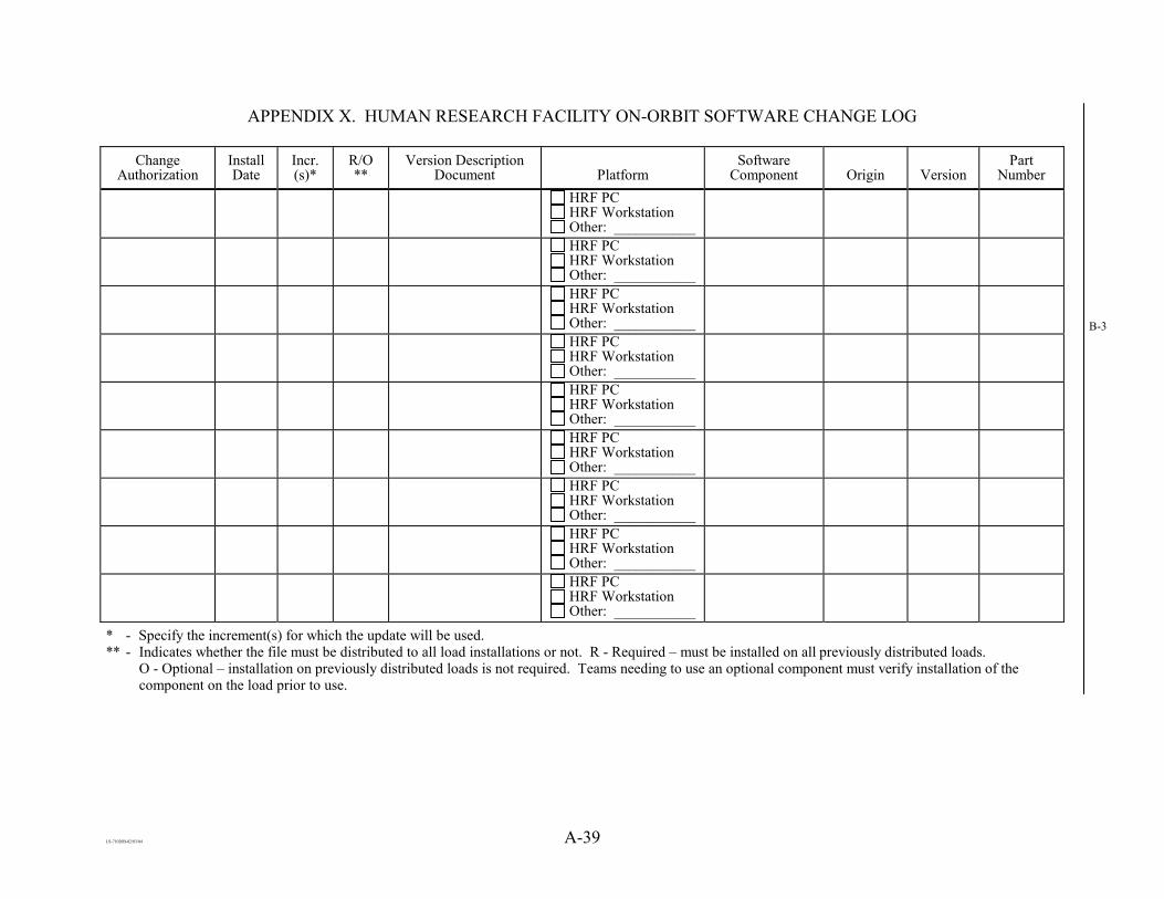
LS-71020B-02/03/04 A-39
APPENDIX X. HUMAN RESEARCH FACILITY ON-ORBIT SOFTWARE CHANGE LOG
Change Authorization
Install Date
Incr. (s)*
R/O **
Version Description Document Platform
Software Component Origin Version
Part Number
HRF PC HRF Workstation Other: ___________
HRF PC HRF Workstation Other: ___________
HRF PC HRF Workstation Other: ___________
HRF PC HRF Workstation Other: ___________
HRF PC HRF Workstation Other: ___________
HRF PC HRF Workstation Other: ___________
HRF PC HRF Workstation Other: ___________
HRF PC HRF Workstation Other: ___________
HRF PC HRF Workstation Other: ___________
* - Specify the increment(s) for which the update will be used. ** - Indicates whether the file must be distributed to all load installations or not. R - Required – must be installed on all previously distributed loads.
O - Optional – installation on previously distributed loads is not required. Teams needing to use an optional component must verify installation of the component on the load prior to use.
B-3

LS-71020B-11/20/00
APPENDIX B
REVIEW CHECKLISTS

LS-71020B-11/21/00 B-1
B1.0 HRF REQUIREMENTS REVIEW CHECKLIST
HRF REQUIREMENTS REVIEW CHECKLIST
Unit Name:_______________________________ Date: ____/_____/_____ Reviewer: _______________________________ Date: ____/_____/_____ Comments:____________________________________________________________________ _____________________________________________________________________________
Init Activity Lessons learned files from other projects have been reviewed for applicability Data package distributed two weeks prior to the review. Review package includes cover memo, Hardware Development Plan (or other system
approach documentation), schedule, data package contents list, other applicable material (list: )
Lessons learned have been generated and placed in SDF with copy to SEAT Quality Systems Deployment Rep?
Closure Authorization Contractor:________________ Date_______ NASA:___________________ Date________
Revision: A [11/21/2000]

LS-71020B-11/21/00 B-2
B2.1 HRF SOFTWARE PRELIMINARY DESIGN REVIEW CHECKLIST
HRF SOFTWARE PRELIMINARY DESIGN REVIEW CHECKLIST
Unit Name:__________________________________ Date: ____/_____/_____ Reviewer: __________________________________ Date: ____/_____/_____ Comments:____________________________________________________________________ _____________________________________________________________________________
Init Activity Data package distributed two weeks prior to the review. Review package includes cover memo, Requirements documentation (HRD or other), schedule, data
package contents list, other applicable material (list: )
Relationship/dependencies with other units is described. Design constraints and assumptions are specified. SDF up to date and contains requirements, interface and design information. Lessons learned have been generated and placed in SDF with copy to SEAT Quality Systems
Deployment Rep? First occurrence of each acronym defined. No open issues/questions (record any open as action items). Architecture for CSCI (decompose to CSU with calling hierarchy). If user interface, screen shots have been submitted to the HRF Display Review Process. Each Requirement is specified by a “shall.” Only one requirement per “shall” (no compound requirements) with a unique identifier per “shall.” Initialization and shutdown requirements are completed (if applicable). Each “shall” is quantifiable per the verification method specified. Each “shall” addresses an observable behavior or characteristic. All expected software functions have been documented. Traceability and Allocation tables completed, and accurate.
Closure Authorization Contractor:________________ Date_______ NASA:___________________ Date________
Revision: A [11/21/2000]

LS-71020B-11/21/00 B-3
B2.2 HRF SOFTWARE CRITICAL DESIGN REVIEW CHECKLIST
HRF SOFTWARE CRITICAL DESIGN REVIEW CHECKLIST
Unit Name:__________________________________ Date: ____/_____/_____ Reviewer: __________________________________ Date: ____/_____/_____ Comments:____________________________________________________________________ _____________________________________________________________________________
Init Activity Data package distributed two weeks prior to the review. Review package includes cover memo, Requirements documentation (HRD or other), schedule, data
package contents list, other applicable material (list: )
Relationship/dependencies with other units is described. Design constraints and assumptions are specified. SDF up to date and contains requirements, interface and design information. Lessons learned have been generated and placed in SDF with copy to SEAT Quality Systems
Deployment Rep? First occurrence of each acronym defined. No open issues/questions (record any open as action items). All algorithms are identified and described with enough detail to implement. Data names follow naming conventions (SDP, Appendix C). Data structures are identified and describe with enough detail to implement. Each requirement traced through design. Error handling is identified and described with enough detail to implement. Flow logic is correct and complete. I/O sections complete. Inputs and outputs are traceable among the CSUs. Local data elements are identified. No dependencies on direct memory locations except as dictated by target architecture. Processing that binds code to target architecture word size should be avoided. Software design documentation adheres to template (SDP, Appendix A). Draft Test Plans are available for review. If user interface, Prototype User Interface S/W has been submitted to the HRF Display Review Process.
Closure Authorization Contractor:________________ Date_______ NASA:___________________ Date________
Revision: A [11/21/2000]

LS-71020B-11/21/00 B-4
B3.0 HRF CODE REVIEW CHECKLIST
HRF CODE REVIEW CHECKLIST
Unit Name:__________________________________ Date: ____/_____/_____ Reviewer:___________________________________ Date: ____/_____/_____ Comments: ____________________________________________________________________ ______________________________________________________________________________
Init Activity The SDF, SDD requirements documentation (HRD or other) excerpts and list of open issues are available at
the review. All objects are declared with a specific data type. Objects are initialized or set before being referenced. For every memory allocation, there exists a corresponding "free". After the “free,” is the pointer set to null. Codes compiles without warnings or errors. If freeing memory in another routine, is this documented in the header or comments? All objects of a link list are freed. Every call to strncpy is followed by a forced null character. For every open, there is a corresponding close. No nested header files. No multiple declared headers. (a header files is included once in a file) Void subprograms have either no return statement or no parameter on the return statement. At most, one return per subprogram. (except for error returns) No gotos. Prototype in proper place (header file or subprogram). Subprogram returns 0 if failure; returns 1 if successful. On multiple error return values, subprogram returns
> 0 if failure; returns 0 if successful. Is error handling / out-of-bounds checking sufficient? All declared variables are used in the code. Enumeration types are used instead of integer types (hard-coded integers). Switch statements are used instead of an if for selections. Switch statements contain the default clause. Break statement is the last statement in each case of a switch statement, except in Visual BASIC. Avoid modifying an object's value more than once in a single statement. Avoid exceeding array or allocated memory boundaries. SDF complete and up to date.
Closure Authorization Contractor:________________ Date_______ NASA:___________________ Date________
Revision: A 12/13/99

LS-71020B-11/21/00 B-5
B4.0 CODE REVIEW REPORT CSCI Title: Date: _____/_____/_____ Attendees Comments/Redlines/Recommendations:
All comments, redlines, and recommendations have been addressed accordingly. Responsible Engineer(s): Data / / Project Manager: Data / / SQA: Date / / Date / /
Revision: Original [11/21/2000]

LS-71020B-11/21/00 B-6
B5.0 CSCI INTEGRATION TEST SIGNOFF FORM CSCI Title: Initial Thread Version: CSCI Developer(s): All CSUs promoted for Integration and Unit Test completed. Test Runs*:
Run Date(s) Run Without Errors?
(Yes/No.) Tester Name (Print) Tester Signature
*Two test runs without errors must be executed in succession before the integration test of the CSCI is accepted. The CSCI developer may not execute integration test.
In lieu of formal integration testing due to DRs or other unlikely occurrences, record test actions performed:
Thread promoted for Integration Test completion. Promoted Thread Version:
Integration Test Complete Acceptance: Responsible Engineer(s): Data / / Project Manager: Date / /
Revision: Original [11/21/2000]

LS-71020B-11/21/00 B-7
B6.0 SYSTEM INTEGRATION TEST SIGNOFF FORM CSCI Title: Initial Thread Version: CSCI Developer(s): All CSUs promoted for System Integration and CSCI Integration completed. TPS Number (System Evaluation):
Run Date(s): Run Without Errors? (yes/no) Comments: Tester Name (Print): Tester Signature
Record the evaluation with any problems for the System Integration Test.
Thread promoted for System Integration Test completion. Promoted Thread Version: System Integration Test Complete Acceptance: Tester(s): Data / / Data / / Revision: Original [11/21/2000]

LS-71020B-11/21/00 B-8
B7.0 QUALIFICATION READINESS REVIEW CHECKLIST CSCI: Version: Test Status: Hardware availability: Support Personnel Required (outside of team members): Documentation Status:
Test Plans - Design Documentation - VDD - Other -
Configuration Status: Open Issues: Project Manager: SQA: NASA:
Use the back of this form to record attendance and other information that will not fit in the space provided. Revision: Original [11/21/2000]

LS-71020B-11/21/00 B-9
B8.0 COMPILER SETTINGS See the following file(s): in the thread, version , for the compiler settings. / / Developer Revision: Original [11/21/2000]

LS-71020B-11/21/00 B-10
B9.0 DOCUMENT REFERENCE CSCI Title: Version:
Document Release Number/Section Initial*
HARDWARE REQUIREMENTS DOCUMENT (HRD) OR SOFTWARE REQUIREMENT SPECIFICATIONS (SRS)
Software Design Document (SDD)
INTERFACE DEFINITION DOCUMENT (IDD) OR INTERFACE CONTROL DOCUMENT (ICD)
Test Plan
Version Description Document (VDD) *NASA representative and project manager must initial if the document is not applicable.
Revision: Original [11/21/2000]

LS-71020B-11/21/00 B-11
B11.0 CSCI SDF CHECKLIST CSCI Title: Version:
Initial* Item Date
Submitted
Code Review Invitation Page
CODE REVIEW CHECKLIST
Razor Code Version List (Code Review)
Code Review Comments
Code Review Report
Integration Test Sign-Off
System Integration Test Sign-Off
Qual. Readiness Review Minutes
Qual. Test Results (Test Procedure, TPS, DR)
Razor Code Version List (Release)
Compiler Settings (Release)/Operating System
DOCUMENT REFERENCE
JSC Project Parts Tag (911)
JSC Program Stock Transfer/Receiver/Shipper Form (528)
Revision: Original [11/21/2000]

LS-71020B-11/20/00
APPENDIX C
HRF CODING STYLE GUIDE

LS-71020B-11/20/00
Typographical Conventions
The font style conventions illustrated in Table C-1 are used throughout this document to identify special text.
TABLE C-1 FONT STYLES FOR SPECIAL TEXT
(OTHER THAN HEADINGS)
Text Text Style Example C Reserved Words or Standard Files
Italics main, extern, errno.h
Examples Bold Italics My_File_Name

LS-71020B-11/21/00 C-1
C1.0 INTRODUCTION C1.1 PURPOSE
This document is intended to be a coding style guideline for C code written for Human Research Facility (HRF) systems. It is not intended to be a rule book. Rather, it is intended to provide guidelines to improve code readability and portability. Many of these guidelines may be superseded by unique requirements imposed by a Commercial Off the Shelf (COTS) product or by the need to improve software performance.
C1.2 SCOPE
This document defines the program structure for all C coded Computer Software Configuration Items (CSCIs) and libraries within the HRF. It also specifies general guidelines that should be used to ensure sound design, implementation, and overall clarity and maintainability of the code. General naming conventions are specified, as are guidelines for commenting the code. A set of formats is provided as examples to help ensure a consistent look and feel among code written by a wide range of developers. The concepts presented shall be applied to other programming languages used for HRF software development as appropriate. Finally, Section C6.0, C Code Samples, contains some C code examples that incorporate the guidelines specified throughout the text of this document.
C2.0 PROGRAM STRUCTURE C2.1 COMPUTER SOFTWARE CONFIGURATION ITEM (CSCI)
A CSCI is an aggregation of software or firmware that satisfies an end use function and is designated for configuration management. In general, each CSCI has a main routine that ties together all of the component routines into a cohesive functional unit. Occasionally, a CSCI may consist of multiple main routines. These cases are clearly identified and an explanation for the multiple main routines is provided in the corresponding software design document.
C2.2 COMPUTER SOFTWARE UNIT (CSU)
A source file containing one or more functions used to build a CSCI. If a CSU consists of more than one function, the functions should work together to execute part of the CSCI design.
C2.3 LIBRARIES
A library is a special type of CSU that is a collection of functions that are used by one or more CSCIs and linked with the CSCI main function at compile time. A library by itself serves as a repository of function object code. This limits the amount of software that must be recompiled when a CSCI component is changed.

LS-71020B-11/21/00 C-2
C2.4 SOURCE FILES
Source files contain all of the C code, data declarations and functions for a CSCI. The contents of a source file may represent a CSCI, a CSU or a library.
C2.5 HEADER FILES
Header files contain all of the constants, typedefs, structures, unions, enumeration types, macros and function prototypes required for the successful compilation of the CSCI or library.
C2.6 PROLOGUES
The following prologue shall be included at the beginning of each source or header file: /******************************************************************* * * FILENAME: filename.type * * DESCRIPTION: Description * * CSCI IDENTIFIER: HRF-xyyz * *******************************************************************/ Where:
filename is the name of the file and indicates the purpose of the file contents. type represents the type of file, e.g. .c for C source files and .h for header files. Description is a brief summary of the file contents. If the content is a main
function, the operation of the CSCI shall be included. For individual functions, function utilization information shall be provided. For function collections or libraries, rationale for grouping the functions shall be provided.
HRF-xyyz is the unique identifier associate with a CSCI, see the Human Research Facility Software Configuration management Plan and Procedure. If the file is associated with multiple CSCIs, all of the associated CSCI unique identifiers shall be listed.

LS-71020B-11/21/00 C-3
See Naming Conventions for more information.
If a file contains more than one function, the following prologue shall precede each function in the file:
/******************************************************************* * * FUNCTION: FunctionName * * DESCRIPTION: Function description including usage. * *******************************************************************/
C3.0 GENERAL GUIDELINES C3.1 DESIGN CONSIDERATIONS
The set of design techniques collectively described as "top down" shall be applied to a CSCI as detailed below:
· Partitioning should be used so that interdependencies between functions are
minimized (i.e., loosely coupled). Each function should have a well-defined purpose or algorithm.
· Hierarchical relationships should be enforced so that functions at one level can
only invoke functions at a lower level. Typically, upper-level functions contain primarily decision and control logic, while the lower-level functions perform specific application tasks.
C3.2 IMPLEMENTATION CONSIDERATIONS
A C compiler should be set at the most stringent level of error checking possible for that compiler. The makefile facility should be used to control compile sequences. VG2C Executing code shall not dynamically modify itself or any other executable code. Only the data associated with a CSCI may be modified. When working on systems that support signal processing, the use of signal handlers is strongly encouraged. This enables developers to produce meaningful error messages or avoid error messages altogether by using the appropriate user-defined signal handlers signal and perror and the include file errno.h.

LS-71020B-11/21/00 C-4
C3.3 PORTABILITY RULES
A portable function is platform or machine independent. Any environment-specific and machine-specific code should be isolated and localized as much as possible. It should also be delimited with appropriate compiler directives. Due to the C compiler aligning data types at certain byte boundaries, order members in a structure by data type length, longest first, whenever possible (i.e. 8-byte variables first, then 4-byte variables, 2-byte variables, etc.). This may not be possible when interfacing with external functions or hardware. System-defined symbolic constants such as NULL, EOF, "/f", etc., should be used. This usage promotes readability and portability between systems. Avoid hard-coding character strings into the code. Instead, use #define constructs or read the strings from a database at execution time. The following data types should be used because their length and format are standard across most modern architectures:
Description Data Type Length (Bytes) ASCII Characters: char 1 Signed Integer Numbers:
char 1
short 2 int 4 Unsigned Integer Numbers:
unsigned char 1
unsigned short 2 unsigned long 4 Floating Point Numbers: float 4 double 8
The absolute path name of an #include statement should not be specified in the code. Instead, the directory of the include file (or reference directory for #include statements with relative path names) should be included as an argument on the C compiler's command line in the CSCI makefile. For example:
cc -I- -I. -I/home/project_name file_a.c -lm /* UNIX format */

LS-71020B-11/21/00 C-5
C3.4 EXPRESSIONS
Complex or compound expressions in which the order of evaluation is important shall be avoided. For example, in the expression "Array[i++] = Value;", Value will be assigned to a different element in Array depending on whether i is incremented before or after the assignment takes place. This expression should be written as two separate expressions: Array[i] = Value; i++; /* if i is to be incremented after the variable assignment */ or i++; Array[i] = Value; /* if i is to be incremented before the variable assignment. */ To avoid Side Effects, "++" and "--" shall not be used within another expression. Rather, when these operators are needed, they shall be used on their own line. A for loop increment operation is the only exception.
Braces "{}" shall be used in conjunction with indentation to delineate complex logic. The braces should be vertically aligned. For example: for (i=0; i<5; ++i) { _ } Parentheses "()" should be used as necessary to enforce efficient expression evaluation. Mixed-mode operations (i.e. multiplying integer and real identifiers) should be avoided. If operations need to be performed on mixed types, an explicit type cast should be used. Complicated compound negative Boolean expressions should be avoided. Whenever possible, Boolean expressions should be evaluated as True=1 and False=0. The use of the conditional expression operator "?" is discouraged. The sizeof function should be used to determine the amount of memory a data item uses, because the actual size of a data item is often not what is expected. This also maintains the portability of code. The goto statement shall not be used. Use of the continue statement is discouraged.

LS-71020B-11/21/00 C-6
The use of break to exit a looping construct is discouraged. The return statement, when used, should be the last statement within a function. The only exception is for implementing error handling. Avoid putting return statements inside if or loop constructs where the return statement could be skipped. Each CSCI should have only one exit statement, which should be the last executable statement in the main routine. The only exception is for implementing error handling.
C3.5 IDENTIFIERS C3.5.1 Global Data
In general, the use of global data should be avoided in C code. In the cases where global data is needed to meet performance or data visibility requirements, the following guidelines should be used: Combine all of a CSCI's global data into a data structure in the CSCI's header file. Declare a variable, using the data structure defined in step 1, in the CSCI's main. Declare the variable as extern, using the data structure defined in step 1 and the identifier name from step 2, in the other CSU source files associated the CSCI. An algorithm that prevents simultaneous access by two or more CSCIs should protect identifiers that are shared between multiple CSCIs.
C3.5.2 Local Data Temporary (local) memory should be used whenever possible in order to improve processing speed.
C3.5.3 Input/Output Data Precautions shall be made to ensure consistent input data (i.e. the input data shall not be allowed to change while operations are being made on that data).
Some input data words from external subsystems have unused bits that by convention are not set and are referred to as "don't care" bits. However, the code should treat these bits as if they were variable. Usually, this means masking out the "don't care" bits before they are used internally. Multiple stores into a global output identifier should be avoided, whenever possible, to prevent intermediate values from being accessed by another function. Instead, store intermediate values in local identifiers where they are not available to other functions. Before exiting the function, copy the local value to the global location.

LS-71020B-11/21/00 C-7
C3.5.4 Pointers Dynamically allocated identifiers should only be used when necessary. In all cases where an identifier is dynamically allocated, its memory shall be explicitly freed before the CSCI terminates. Pointer data types should not be mixed when assigning one pointer identifier to another. When declaring a pointer, it should be initialized to a value of NULL or to the intended object. This makes it easy to determine whether or not a pointer has been assigned. Pointers should be initialized or verified to ensure the pointer is not NULL prior to use. Manipulation of "pointers to functions" should be limited. This is an extremely powerful practice, but when used improperly, it can cause system failures that can be extremely difficult to resolve. If "pointers to functions" are used, strict type adherence shall be maintained. The same consideration shall be made for "pointers to pointers" or "handles".
C3.6 DECLARATIONS
The scope of identifiers and functions shall be as local as possible to maintain the integrity of the system and to discourage outside access to a function's internal data. All variable to be used in a function shall be declared at the beginning of the function. This avoids variable scope issues that can cause confusion when variable declarations are embedded in control constructs (e.g. if, while, etc.). Statements that attempt to define a data type and declare a variable within the same statement should be avoided. Instead, define the data type in a header file, then declare the variable in a source file using the new data type. Multiple identifier declarations (more than one user identifier in an identifier list) should be avoided. Exceptions can be made for insignificant identifiers, such as loop counters. All identifiers and functions shall be explicitly declared (e.g. short, int, double). Avoid using "default" function declarations. Identifiers shall be of declared types defined in a header file or the standard C types (e.g. double, int, short, char). [S]tatic identifiers should be used only when necessary to maintain the value of an identifier from invocation to invocation of a code block.

LS-71020B-11/21/00 C-8
The use of register identifiers should be avoided, except in cases where improved speed is absolutely necessary.
C3.7 FUNCTIONS
Each function shall have a prologue. If a source file contains only one function, however, the standard source file prologue will suffice. See Section C2.6, Prologues, for more information. The behavior of each function shall adhere to the following considerations:
· Strong internal cohesion — A function has strong internal cohesion if it is
designed to implement a single function or a set of closely related operations. Poor internal cohesion is demonstrated by a function that is designed to implement two or more unrelated operations (i.e. to calculate the time and find the square root of a number).
· Loose external coupling — A function has loose external coupling if it is
designed so that its functioning is not affected (as much as possible) by changes made internally to other functions.
· Ease of understanding and readability. · Ease of testing · Portability · Maintainability · Abstraction - Functions should be designed so that a programmer can use a
function by passing the appropriate arguments, but the programmer would not need to know the implementation details of the function.
In instances in which the order of evaluation of functions is important, the required order of processing shall be stated explicitly in comment fields within the code. A function prototype statement shall exist in a header file for each function to be used. Functions contained in the Standard C Libraries are exempt. It is a good practice to keep functions as short as possible (i.e. more functions with less executable statements per function) in order to improve modularity. This concept is encouraged in most cases, especially for library functions. Be careful, however, because the incurred overhead associated with an increased number of function calls can degrade execution speed.

LS-71020B-11/21/00 C-9
With the exception of error handling, the set of design techniques collectively described as "top down" shall be applied for each function as detailed below:
· Each function shall have one entry and one exit. · Each function shall return to its calling function. · The logic of each function shall be simplified as much as possible, without
adversely affecting the ability of the function to meet its requirements.
In general, recursion should not be used, since it may decrease execution efficiency as a result of overhead.
C3.7.1 Interfaces
Interfaces should be kept as simple as possible. The number of inputs and outputs should be minimal. Functions that do not return a value to the calling routine should be declared as void functions. All functions shall be explicitly declared (e.g. short, int, double). Avoid using "default" function declarations. Typically, interfaces will be as explicit (i.e. arguments passed through a parameter list) and as simple as possible. Global data should be avoided, when possible. Structure and union parameters should be passed by reference to user-defined functions (i.e. pass the address rather than the contents of the structure/union).
C3.7.2 Side Effects Side effects are defined as changes to identifiers outside the scope of the function. An example is modification of the function's actual parameters during the call of a function rather than inside the function (e.g. passing i++ as a parameter). Side effects should be avoided, because their impacts are typically not obvious and are difficult to test, and they cause a function to be unnecessarily tightly coupled. If side effects are necessary, then a comment describing all of the side effects of the function shall be included in the prologue and design document.
C3.8 HEADER FILES
Header files contain all constants, typedefs, macros, and function prototype statements for a CSCI or library. Source files only contain identifier declarations of these types.

LS-71020B-11/21/00 C-10
When possible, put the interface constants, types, macros, and function prototypes in a separate file from the internal constants, types, macros, and function prototypes.
Each header file shall contain a prologue as specified in Section C2.6, Prologues. Data shall not be declared in header files, since each inclusion of the file creates a copy of the data. Header files shall not contain any executable code. Including other header files from within a header file is discouraged in all cases. The only exception is if a subsequent statement within the header file absolutely requires something contained within another header file. These instances should be avoided if at all possible, however.
Header files should be protected from multiple inclusions by using the following construct: #ifndef FILE_NAME_H /* header file contents */ #define FILE_NAME_H #endif
C3.8.1 Type Definitions
A typedef should be used to define new types for all structures, unions, and enumeration types. A typedef should be used if several identifiers are going to be used for a common purpose and declared the same way (e.g. typedef int SEMAPHORE_TYPE). [T]ypedef statements that modify other user-defined typedefs (e.g. typedef MEM_TYPE *MEM_TYPE_PTR) should be avoided, because the true nature of the data type becomes difficult to track. The use of the union declaration is strongly discouraged.
C3.8.2 Constants The use of global constant declarations (#define), which symbolically name constants that occur frequently in one or more function blocks or programs or that have a recognizable significance, is strongly encouraged. Constants should be used to ensure data consistency and integrity and to improve clarity. They should not be used simply to reduce the amount of typing within the

LS-71020B-11/21/00 C-11
source code (e.g., #define FNAME Global->file_name is not recommended). Overuse of constants can make the source code difficult to read because of frequent references to the header file contents. The use of the const type qualifier is similar to #define except that const variables can have a local scope when they are declared within a function.
C3.8.3 Macros
Macros should be used to enhance readability and maintenance, to save the overhead of a function call, or to reduce the complexity of an expression. They should not be overused (e.g., #define GET_FILE_NAME(a) a.file_name), because frequent references to the header file contents can make the source code difficult to read. Each macro shall be preceded by a function prologue. If a macro contains a control construct (e.g., if...else, for, while, switch, etc.), the entire construct shall be defined in the macro definition. A starting and ending macro combination is not acceptable.
Define a macro whenever the value is determined at run-time, otherwise create a constant if the value can be determined at compile time. Macros should be defined to look like function calls. If a more robust function is required of the macro, it can be replaced by a function without changing any of the calling source code.
C3.8.4 Function Prototype Statements
As previously stated, function prototypes should be placed in the header file and should be formatted as follows:
function_type function_name(parameter_1_type in_1,
parameter_2_type in_out_1, parameter_3_type in_out_2, parameter_4_type out_1,
� � �
parameter_n_type direction_n); Where in_1 is an input to the function (not modified), in_out_1 and in_out_2 are inputs to the function that are modified by the function, and out_1 is a parameter that is only passed to the function to be modified.

LS-71020B-11/21/00 C-12
C4.0 NAMING CONVENTIONS C4.1 FILE NAMES C4.1.1 CSCI File Names
Following are naming conventions to be used for the CSCI abcd: Executable: abcd* Source File(s): abcd_*.c Header File: abcd.h ** * No convention, but developers are encouraged to include abcd somewhere in the filename, preferably at the beginning (e.g., abcd_valve.c). If there is only one source file associated with a CSCI, the recommended name is abcd.c. ** Ideally, each CSCI should have a single header file. If multiple header files are required for the sake of clarity, each header file shall include abcd somewhere in the filename, preferably at the beginning (e.g., abcd_macro.h).
C4.1.2 CSU File Names
Following are naming conventions to be used for the CSU lmno: Executable: lmno* Source File(s): lmno_*.c Header File: lmno.h** * No convention, but developers are encouraged to include lmno somewhere in the filename, preferably at the beginning (e.g., lmno_valve.c). If there is only one source file associated with a CSU, the recommended name is lmno.c. ** Ideally, every CSU should be a component of one CSCI or become part of a library. In the ideal situations, the CSCI or library header file should be used. If a CSU header file is required for the sake of clarity, each header file shall be called lmno.h.
C4.1.3 Library File Names
Following are naming conventions to be used for the library wxyz: Library: lib_wxyz.a* Source File(s): lib_wxyz_*.c Header File: lib_wxyz.h ** * No convention, but developers are encouraged to include wxyz somewhere in the filename, preferably at the beginning (e.g., lib_wxyz_math.c). If there is only one library source file, the recommended name is lib_wxyz.c.

LS-71020B-11/21/00 C-13
** Ideally, each library should have a single header file. If multiple header files are required for the sake of clarity, each header file shall include wxyz somewhere in the filename, preferably at the beginning (e.g., wxyz_macro.h).
C4.2 IDENTIFIER NAMES
Descriptive names for user identifiers based on functionality and/or use shall always be used. Identifier names, with the exception of loop counters and indices (e.g., "i", "j"), shall be longer than two characters. Identifier names should use underscores as word breaks. Two or three words make variable names long enough to be easily understood. Note that in ANSI/ISO C, the first 31 characters in a variable name are significant and therefore must be unique. Identifier names shall not begin with an underscore (except for identifiers declared in macros). Identifiers should not differ only by the presence/absence of underline characters, the interchange of capital letters with lower-case letters, or the interchange of symbols that look similar (e.g. "O" and "0", "l" and "1", "S" and "5", etc.). Identifier names for pointer variables shall be prefixed by "p_", pointers to pointers shall be prefixed by "pp_", etc. Function identifiers shall be in mixed case. Each separated word shall begin with an uppercase letter followed by all lowercase letters to improve readability. Words may be additionally separated using underscores. Each function identifier should contain the name of the CSU associated with the function as the last characters of the identifier. For example, a function in the Linked List CSU that inserts a cell into a linked list might be called Insert_Cell_Linked_List. Global object identifiers shall begin with an uppercase letter followed by all lowercase letters, while local object identifiers shall be all lowercase. Underscores shall be used to separate words within the global object identifier to enhance readability. For example, a global object containing the Workstation task list might be called Workstation_task_list, while a local version of the same object would be local_task_list.
Constant, typedef and macro names shall be in all uppercase with underscores used to separate words.

LS-71020B-11/21/00 C-14
C5.0 FORMATS C5.1 FILE FORMATS C5.1.1 CSCI Source File Format
A CSCI source file is structured as follows:
1. Prologue — Comment information used to track changes, etc.
2. Include Statements — Header files, including system header files (enclosed by <>), library header files (enclosed by ""), and the CSCI header file (also enclosed by "").
3. Global Data Declarations — Declarations for all data global to the CSCI, including shared memory data. Note that this data is either a standard C data type (float, short, char, etc.) or a type that is defined in one of the above header files.
4. The main function of the CSCI, which calls functions from other source files that comprise the CSCI.
C5.1.2 CSU Source File Format
All CSU source files, with the exception of the CSCI source file, are structured as follows:
1. Prologue — Comment information used to track changes, etc.
2. Include Statements — Header files, including system header files (enclosed by <>), library header files (enclosed by ""), and the CSCI header file (also enclosed by "").
3. Global Data Declarations — Declarations for all data global to the CSCI, including shared memory data. Note that this data is either a standard C data type (float, short, char, etc.) or a type that is defined in one of the above header files, and is preceded by the word extern, which specifies that the variable has been formally declared elsewhere (in the CSCI Source File).
4. One or more functions that perform operations required for the CSCI.
Note that this format differs from the format of a CSCI source file in two ways:
1. This file contains one or more functions, as opposed to a main, which is a CSCI master sequencing routine; and
2. All global data declared in this file are defined as extern, because they are formally declared in the CSCI source file.
LS-71020B-11/21/00 C-15
C5.1.3 Library Source File Format
All library source files are structured as follows:
1. Prologue — Comment information used to track changes, etc.
2. Include Statements — Header files, including system header files (enclosed by <>) and the library's header file (enclosed by "").
3. One or more functions that perform a task provided by the library.
Note that this format differs from the format for CSU source files in two ways:
1. There are no CSCI header files included within a library source file; and
2. There are no global data declarations within a library — all library functions are self-contained.
C5.1.4 Header File Format All header files are structured as follows:
1. Prologue — Comment information used to track changes, etc.
2. Constants — #define statements used to equate a constant value with a string.
3. Typedefs, Structures, Unions and Enumeration types — C constructs used to improve code readability and maintainability.
4. Macros — #define statements used to substitute a common series of statements throughout the CSCI/library with a simple string and accompanying arguments.
5. Function Prototypes — Prototypes, including argument list specifications, for all functions within the CSCI/library.
C5.2 COMMENT FORMATS
The purpose of comments is to serve as an aid for someone unfamiliar with the code. Comment WHY something is happening not just WHAT is happening. Every functional block of code shall be explained by a comment. Block comments should be indented to the same column as the following line of code. Comment style shall be consistent throughout a file. Comment style should be consistent throughout all files associated with a CSCI.

LS-71020B-11/21/00 C-16
Comments that encompass multiple lines should begin the first line with a "/*". Each subsequent line should begin with a "*". The last line should end with a "*/". In C++, each comment line should begin with "//". Constants, structures, unions, enumeration types and macros should have comments to describe their overall use. No comments should be embedded within simple executable statements. Blank lines shall be used as necessary to delineate comments. Personal pronouns in comments should be avoided. A formal writing style (third person) should be used with normal capitalization practices (i.e. not entirely uppercase characters). Comments shall not reference specific sections, paragraphs, figures, tables, etc. of documentation that could later change, thereby requiring a change to the code. Comments that document actions outside of a function should be avoided. This ensures that the comments within a function only need to be changed when changes are made to the function itself. Comments pertaining to internal workings of invoked functions may be used if necessary, but are discouraged.
C5.3 EXPRESSION FORMATS
With the exception of complex mathematical expressions, which should be kept to one line whenever possible, each line of code should contain a maximum of 80 characters. There should be a maximum of one statement per line. Blank lines shall be used to enhance readability. For example, each block of code that performs a function should be separated by a blank line. Function definitions, as well as the function's opening and closing braces, should begin in column one. All nesting should be indented at least three spaces from the enclosing braces or the parent structure. Braces should reside on separate lines by themselves and should be indented to the same column as the if, while or for statement with which they are associated.
Continuation of if, while, or for conditions should line up with the starting column of the previous line condition.

LS-71020B-11/21/00 C-17
The connecting logical operator shall go on the same line as if, while or for. No blanks should be encoded around unary operators such as "abs(-10)" or "not(Boolean_Identifier)".
A blank space should be encoded on both sides of all binary operators. For example, "X = X + 1", not "X=X+1".
C5.3.1 The if...else Statement
The format of the if statement should follow one of the following two forms. Format 2 is preferred. The following examples, demonstrating two coding formats for an if statement, are functionally identical. Condition_1 and Condition_2 are Boolean expressions (complex or simple).
Format 1: if (Condition_1) { /* Comment about statement(s) */ sequence_of_statements . . . } else { if (Condition_2) { /* Comment about statement(s) */ sequence_of_statements . . . } else { /* Comment about statement(s) */ sequence_of_statements . . . } } Format 2: if (Condition_1) { /* Comment about statement(s) */ sequence_of_statements . . . } else if (Condition_2) { /* Comment about statement(s) */ sequence_of_statements . . . } else

LS-71020B-11/21/00 C-18
{ /* Comment about statement(s) */ sequence_of_statements . . . }
The two coding formats are used to increase understandability. Format 1 uses nested if statements and avoids a switch-like structure. Format 2 shows mutually exclusive conditions. It is structured much like a switch statement that always deals with mutually exclusive conditions.
A NULL choice shall be coded by deleting the alternative else completely. Using the second example above, if Condition_1 and Condition_2 cover all possibilities, the final else clause would be deleted.
C5.3.2 The switch Statement
The coding format for a switch statement should be as follows:
/* Comment about statement */ switch (condition) { /* Case 1 comment */ case first_condition: /* Comment about statement(s) */ sequence_of_statement(s) . . . break; /* Case 2 comment */ case second_condition: /* Comment about statement(s) */ sequence_of_statement(s) . . . break; /* Case default comment */ default: /* Comment about statement(s) */ sequence_of_statement(s) . . . break; }
C5.3.3 The while Statement
The format of the while statement should follow one of the following two forms:

LS-71020B-11/21/00 C-19
Format 1: A wait loop (sleep until interrupted) while (condition) { /* Do nothing until interrupted */; } Format 2: A while condition loop (loop while a condition is met) while (condition) { /* Comment about statement(s) */ sequence_of_statements . . . }
C5.3.4 The do Statement
The coding format for a do statement should be a repeat until condition loop (loop until a condition is met) as follows:
do { /* Comment about statement(s) */ sequence_of_statements . . . } while (condition);
C5.3.5 The for Statement
The coding format for a for loop should be as follows:
for (initial_expression; condition; loop_expression) { /* Comment about statement(s) */ sequence_of_statements . . . }
C6.0 C CODE SAMPLES
The following sections contain examples of C source and header files. The example illustrates a simple CSCI, called Force, which is comprised of the following files: force.h (CSCI header file) force.c (CSCI source file) init_force.c (CSU source file 1) proc_force.c (CSU source file 2)

LS-71020B-11/21/00 C-20
Additionally, the Force CSCI accesses the function Square_Root, which is contained in the library Lib_HRF_Math. The Lib_HRF_Math library is comprised of the following files:
lib_hrf_math.h (library header file) lib_hrf_math.c (library source file) Note that the header file lib_hrf_math.h contains the macro DMXM, which isn't used by the Force CSCI, but is used by another CSCI that accesses this library.
C6.1 CSCI HEADER FILE
#ifndef FORCE_H /******************************************************************** * * FILENAME: force.h * * DESCRIPTION: This header file contains constants, typedefs, * macros and function prototypes required by the * Force CSCI. * * CSCI IDENTIFIER: HRF-xyyz * * ORIGINATOR BASELINE DATE AUTH. DOC. * ---------- ------------- ---------- * John. Q. Developer 5/95 SCR 1234 * * REVISED BY BASELINE DATE AUTH. DOC. * ---------- ------------- ---------- * Judy B. Coder 10/95 SDR 1234 * *******************************************************************/ /* Constant Definitions */ #define NUM_VEHICLES 6 typedef enum { False, True } BOOLEAN; typedef struct {
double mass_lbm[NUM_VEHICLES]; double mass_slg[NUM_VEHICLES] double accel[NUM_VEHICLES]; double accel_x[NUM_VEHICLES]; double accel_x[NUM_VEHICLES];

LS-71020B-11/21/00 C-21
double accel_x[NUM_VEHICLES]; double force[NUM_VEHICLES]; BOOLEAN continue_flag; BOOLEAN veh_active[NUM_VEHICLES];
} FORCESTRUCT; /* Macro Definitions */ #define LBM_TO_SLUG(a,b) b = (a) * 0.03108 #define SQUARE(a) (a) * (a) /* Function Prototype Statements */ void Init_Mass(void); void Get_Accel(void); void Force_Calc(void); #define FORCE_H #endif
C6.2 CSCI SOURCE FILE
/******************************************************************* * * FILENAME: force.c * * DESCRIPTION: This is the top-level executive source file for the * Force CSCI, which calculates force for a vehicle * based on mass and acceleration. * * CSCI IDENTIFIER: HRF-xyyz * * ORIGINATOR BASELINE DATE AUTH. DOC. * ---------- ------------- ---------- * John. Q. Developer 5/95 SCR 1234 * * REVISED BY BASELINE DATE AUTH. DOC. * ---------- ------------- ---------- * Judy B. Coder 10/95 SDR 1234 * *******************************************************************/ #include "force.h" FORCESTRUCT Force; main()

LS-71020B-11/21/00 C-22
{ /* initialize mass parameters */ Init_Mass(); /* loop until requested to stop */ while (Force.continue_flag) { /* calculate force after acquiring current acceleration */ Get_Accel(); Force_Calc(); } }
C6.3 CSU SOURCE FILE 1
/******************************************************************* * * FILENAME: init_force.c * * DESCRIPTION: This function initializes the mass values for all * of the vehicles in the current scenario by * converting those values from pounds mass to slugs. * * CSCI IDENTIFIER: HRF-xyyz * * ORIGINATOR BASELINE DATE AUTH. DOC. * ---------- ------------- ---------- * John. Q. Developer 5/95 SCR 1234 * * REVISED BY BASELINE DATE AUTH. DOC. * ---------- ------------- ---------- * Judy B. Coder 10/95 SDR 1234 * *******************************************************************/ #include <stdio.h> #include "force.h" extern FORCESTRUCT Force; void Init_Mass(void) { short i;

LS-71020B-11/21/00 C-23
/* loop once for each vehicle */ for (i = 0; i < NUM_VEHICLES; i++) { /* if a mass is specified, set the vehicle active flag */ /* and convert mass from pounds mass to slugs */ if (Force.mass_lbm[i] != 0) { Force.veh_active[i] = True; LBM_TO_SLUG(Force.mass_lbm[i], Force.mass_slg[i]); } else Force.veh_active[i] = False; } }
C6.4 CSU SOURCE FILE 2
/******************************************************************* * * FILENAME: proc_force.c * * DESCRIPTION: These functions perform the real-time processing * associated with the Force CSCI, which calculates * force based on vehicle accelerations. * * CSCI IDENTIFIER: HRF-xyyz * * ORIGINATOR BASELINE DATE AUTH. DOC. * ---------- ------------- ---------- * John. Q. Developer 5/95 SCR 1234 * * REVISED BY BASELINE DATE AUTH. DOC. * ---------- ------------- ---------- * Judy B. Coder 10/95 SDR 1234 * *******************************************************************/ #include <stdio.h> #include "lib_hrf_math.h" #include "force.h" extern FORCESTRUCT Force; /******************************************************************

LS-71020B-11/21/00 C-24
* * * FUNCTION: Get_Accel * * DESCRIPTION: This function acquires the current acceleration for * each active vehicle in the current scenario. * *******************************************************************/ void Get_Accel(void) { double temp; short i; /* loop once for each vehicle */ for (i = 0; i < NUM_VEHICLES; i++) { /* if the vehicle is active, calculate total acceleration */ /* by summing the acceleration vectors along each axis */ if (Force.veh_active[i]) { temp = SQUARE(Force.accel_x[i]) + SQUARE(Force.accel_y[i]) + SQUARE(Force.accel_z[i]); Force.accel[i] = Square_Root(temp); } } }
/******************************************************************* * * FUNCTION: Force_Calc * * DESCRIPTION: This function calculates the force on each active * vehicle as a product of the vehicle's mass and * acceleration. * *******************************************************************/ void Force_Calc(void) { short i; /* loop once for each vehicle */ for (i = 0; i < NUM_VEHICLES; i++)

LS-71020B-11/21/00 C-25
{ /* if the vehicle is active, calculate force as a product */ /* of mass and acceleration */ if (Force.veh_active[i]) Force.force[i] = Force.mass[i] * Force.accel[i]; } }

LS-71020B-11/21/00 C-26
C6.5 LIBRARY HEADER FILE
#ifndef LIB_HRF_MATH_H /******************************************************************* * * FILENAME: lib_hrf_math.h * * DESCRIPTION: This is the header file for the lib_hrf_math library. * It contains macros and function prototypes for all * CSCIs that use this library. * * CSCI IDENTIFIER: HRF-xyyz * * ORIGINATOR BASELINE DATE AUTH. DOC. * ---------- ------------- ---------- * John. Q. Developer 5/95 SCR 1234 * * REVISED BY BASELINE DATE AUTH. DOC. * ---------- ------------- ---------- * Judy B. Coder 10/95 SDR 1234 * *******************************************************************/ /* Macro Definitions */ #define DMXM(a,b,c) \ c[0][0] = a[0][0]*b[0][0] + a[0][1]*b[1][0] + a[0][2]*b[2][0]; \ c[0][1] = a[0][0]*b[0][1] + a[0][1]*b[1][1] + a[0][2]*b[2][1]; \ c[0][2] = a[0][0]*b[0][2] + a[0][1]*b[1][2] + a[0][2]*b[2][2]; \ c[1][0] = a[1][0]*b[0][0] + a[1][1]*b[1][0] + a[1][2]*b[2][0]; \ c[1][1] = a[1][0]*b[0][1] + a[1][1]*b[1][1] + a[1][2]*b[2][1]; \ c[1][2] = a[1][0]*b[0][2] + a[1][1]*b[1][2] + a[1][2]*b[2][2]; \ c[2][0] = a[2][0]*b[0][0] + a[2][1]*b[1][0] + a[2][2]*b[2][0]; \ c[2][1] = a[2][0]*b[0][1] + a[2][1]*b[1][1] + a[2][2]*b[2][1]; \ c[2][2] = a[2][0]*b[0][2] + a[2][1]*b[1][2] + a[2][2]*b[2][2]; /* Function Prototype Statements */ double Square_Root(double); #define LIB_HRF_MATH_H #endif

LS-71020B-11/21/00 C-27
C6.6 LIBRARY SOURCE FILE
/******************************************************************* * * FILENAME: lib_hrf_math.c * * DESCRIPTION: These functions perform standard mathematical * calculation used in math models throughout the HRF. * * CSCI IDENTIFIER: HRF-xyyz * * ORIGINATOR BASELINE DATE AUTH. DOC. * ---------- ------------- ---------- * John. Q. Developer 5/95 SCR 1234 * * REVISED BY BASELINE DATE AUTH. DOC. * ---------- ------------- ---------- * Judy B. Coder 10/95 SDR 1234 * *******************************************************************/ #include <lib_math.h> #include "lib_hrf_math.h" /******************************************************************* * * FUNCTION: Square_Root * * DESCRIPTION: This function returns the square root of the input * variable to the calling routine. For negative * input values, this function returns a zero. * *******************************************************************/ double Square_Root(double input) { double output; double temp; if (input <= 0) /* square root of 0 is 0, and the square root of a */ /* negative number is undefined */ output = 0;

LS-71020B-11/21/00 C-28
else if (input == 1) /* square root of 1 is 1 */ output = 1; else { temp = log(input); output = exp(0.5 * temp); } return(output); }

LS-71020B-06/15/01
APPENDIX D
HRF SOFTWARE TESTING GUIDELINES
B-1

LS-71020B-10/02/01 D-1
D1.0 INTRODUCTION The procedure/guidelines outlined below shall be used with flight software that is downloaded from an Internet or File Transfer Protocol (FTP) site, or received from International Partners, Principle Investigator Teams, Vendors and non-HRF NASA organizations. The process to be followed is determined by: 1. The absence or presence of a Certificate of Compliance (COC) with software when it is
delivered to the responsible HRF team as follows:
Software Origin Responsible HRF Team
International Partners HRF Instrument Team
Principle Investigator HRF Experiment Team
Vendors HRF team that purchased and/or requested the software
Non-HRF NASA organization HRF team assigned to monitor software development and delivery
The COC states that the software is: Free of viruses Has met all requirements For software generated before January 1, 2000 or for software containing components that were generated before January 1, 2000, the COC must state that the software is “Year 2000 Compliant.” The presence of the COC allows the software to be delivered to bonded storage.
2. The source of the software, that is if the software was received on physical media (floppy, CD, etc.) versus download from an Internet or FTP site. Regardless of the process followed, a Software Test Readiness Checklist shall be completed and a copy presented to Software Quality with the Task Performance Sheet (TPS) to ensure that all required equipment, documentation, and personnel are available. The responsible HRF team should: Provide names and phone numbers of people responsible for the software that would be
available for questions Provide a software test plan or test steps, a Version Description Document and any changes
to these documents. Ensure coordination of lab space to run the test and the necessary on-site personnel for
specific equipment. Schedule activities with SQA personnel. If a test requires a subject, ensure that the necessary paperwork is at the test site and the
required medical supervision arranged before the test is conducted.
B-1

LS-71020B-10/02/01 D-2
Deviations to this process are allowed under special circumstances. Should a process deviation be used, the deviation should be documented, including rationale, in a memo to file and signed by the Project Manager and SQA representative. The responsible HRF team, in conjunction with software quality assurance, performs all actions described below using flight or flight equivalent hardware, unless instructed to use other hardware. GSE hardware will be used when required, particularly in reading the media onto the flight hardware. All actions taken shall be documented on a Task Performance Sheet (TPS) or in a published procedure. Execution of any of the processes described below must be documented on a TPS.
D2.0 SOFTWARE PROCESSES D2.1 PROCESS 1 – SOFTWARE IS DELIVERED WITH A CERTIFICATE OF
COMPLIANCE (COC) 1. Software delivered to Bond 2. Check out software from Bond 3. Perform virus check on software (if virus free statement is missing from the COC) 4. Verify software versions on the media match the versions described in the Version
description Document (VDD) 5. Perform acceptance test on the software to verify quality of media and ability to install and
operate software successfully. 6. Create two working copies of the original software media and label them in accordance with
the HRF Media Part Number and Labeling Guidelines contained in Appendix E of LS-71020. 7. Generate 911 tags. 8. Perform acceptance test on each of the software copies to verify quality of media and ability
to install and operate software successfully 9. Return master copy to bond and check working copies of software into bond. D2.2 PROCESS 2 – SOFTWARE DELIVERED WITHOUT A COC 1. Software delivered to the responsible HRF team. 2. Obtain statement of Y2K compliance from the software originator. This step is not necessary
for data file delivery. 3. Virus check software 4. Verify software versions on the media match the versions described in the Version
description Document (VDD) 5. Test software to ensure it meets all documented requirements. (This test cannot be
performed on flight hardware, must use GSE hardware.)
B-1

LS-71020B-10/02/01 D-3
6. Copy the software on to media to be placed in Bond and label the media in accordance with the HRF Media Part Number and Labeling Guidelines contained in Appendix E of LS-71020. CDs are the preferred media type. One master and two working copies should be made.
7. Generate 911 tags. 8. Perform acceptance test on each of the software copies to verify quality of media and ability
to install and operate software successfully (On flight or equivalent flight unit) 9. Check master copy into bond and working copies of software into bond. D2.3 PROCESS 3 – SOFTWARE DOWNLOADED FROM AN INTERNET OR FTP SITE 1. Verify the version of the software to be downloaded. This information should be contained
in a VDD. 2. Identify the hardware configuration needed to support software testing and schedule all
required resources. 3. Provide proof that the software is free for government use or that the necessary license(s) has
been obtained. 4. Obtain Y2K compliance data from the software originator. This step is not necessary for data
file download. 5. Locate a computer attached to the network. Due to network connectivity, it is not required
that this computer be GSE. 6. Download the software, noting the path to the site. 7. Determine if the download was successful, by looking at checksums, if possible or compare
the size of the file on the site to the size of the file received. NOTE: The exact byte count must be used for this comparison. If the source byte count is
not available, contact the vendor. If the vendor is unable to supply this information, the software must be obtained on media.
8. Perform a virus scan of the software. 9. Compare the version intended to be downloaded and the version actually received. 10. Copy to removable media such as floppy or CD. 11. Continue with Process 1, step 5 if a COC is available for the software, otherwise, continue
with Process 2, Step 4.
B-1

LS-71020B-10/02/01 D-4
SOFTWARE TEST READINESS CHECKLIST
# Action to be completed Stat
us*
Action completed by (print) Date
1 Identify and document the names and phone numbers of people responsible for the software and/or hardware that will be available for questions
2 Lab space to run the test has been coordinated
3 All required hardware and test equipment has been scheduled and is available
4 SQA personnel are aware of the test and test schedule.
5 If a test requires a subject, a copy of the necessary safety paperwork has been obtained and will be brought to the test.
6 If a test requires a subject, required medical supervision has been coordinated for (describe specific medical support scheduled):
7 Document any other special considerations for this test:
*Status = if completed or N/A if not applicable Team is ready to support testing. ________________________________________ Project Manager/Date Form Rev A (10/01)
B-2

LS-71020B-06/15/01
APPENDIX E
HRF MEDIA PART NUMBERS AND LABELING GUIDELINES
B-1

LS-71020B-10/02/01 E-1
E1.0 MEDIA PART NUMBERS This section applies to the part number obtained for CDs, floppy disks, Zip disks and Jaz drives that will be flown aboard the International Space Station in Support of the Human Research Facility (HRF). There should be a one-to-one correspondence between each basic media item (e.g., a CD, a floppy, etc.), its flight part number, and the Version Description Document (VDD) number of the VDD that describes the contents of the basic media item. The dash number should be used to distinguish between Increment releases of the media item. Serial number groups will be used to distinguish between media versions within an Increment. To avoid confusion, previous serial number groups must be downgraded and removed from Bond after the current version is tested and released for the same increment. In the cases where the media item is a set made up of two or more basic media items, the dash number must be used to differentiate between set members (e.g., disk 1, disk 2, disk 3, etc.). Therefore, a new part number must be obtained for each Increment. A new VDD must be generated if the contents of the media set are substantively changed from the previous version (more than 60% of the CD content titles have changed). Serial number groups will be used to distinguish between media versions within an Increment. To avoid confusion, previous serial number groups must be downgraded and removed from Bond after the current version is tested and released for the same increment. In all cases the part name selected should be descriptive of the contents. For example, “HRF Integrated S/W Load – HRF PC” would be a good title for the HRF PC integrated software load CD. E2.0 MEDIA LABELING To ensure consistent labeling of flight software media associated with the Human Research Facility, the following guidelines shall be used: NOTE: There are two Version Description Document (VDD) numbering systems: one for
“Integrated” software and one for “Single Source” software. “Integrated” software would include VDDs for:
• HRF Integrated Rack 1 • HRF Workstation integrated software load (Rack 1) • HRF PC integrated software load (Rack 1) • HRF Integrated Rack 2 • HRF Workstation integrated software load (Rack 2) • HRF PC integrated software load (Rack 2) For “Integrated” software VDDs, a unique LS document number is assigned, and a dash number is used to indicate the version (“versions” are usually associated with one or more increments).
B-2
B-

LS-71020B-10/02/01 E-2
For example, the first version of the VDD for the HRF Integrated Rack 2 would be LS-xxxxx-1. The VDD for the subsequent software release would be LS-xxxxx-2 (where xxxxx is the base document number). For “Single Source” software VDDs, the VDD document number is assigned as a dash number off of a “parent” hardware or software specification document number. In this case, the VDD document number would follow the template: LS-xxxxx-vdd#-version# Where: xxxxx is the document number
vdd is the dash number assigned for the VDD version is the dash number tracking the version of the VDD
For example, the next HRF Common Software VDD update would be released as LS-71062-9-1. The project manager responsible for the software shall determine if the VDD document number should follow the “Integrated” software VDD numbering system or the “Single Source” numbering system. Compact Disks (CDs)
Flight (Class I) CDs
PART NAME INCRYY VDD_DOC_NUM-ZZZ
XXX MM/DD/YY INITIALS
P/N: AAAAAAAAA-BBB S/N: CCCC
Where all letters are capitalized and: YY is the increment number VDD_Doc_Num is the document number of the Version Description Document (VDD) ZZZ is the document dash number representing the VDD version XXX is the integrated software version MM/DD/YY is the date the media was made INITIALS is the initials of the media builder AAAAAAAAA is the primary part number BBB is the part dash number CCCC is a unique serial number
B-2

LS-71020B-10/02/01 E-3
Class II/GSE CDs
PART NAME INCR YY VDD_DOC_NUM-ZZZ
XXX MM/DD/YY INITIALS
P/N: AAAAAAAAA S/N: CCCC
Where all letters are capitalized and: YY is the increment number VDD_Doc_Num is the document number of the Version Description Document (VDD) ZZZ is the document dash number representing the VDD version XXX is the integrated software version MM/DD/YY is the date the media was made INITIALS is the initials of the media builder AAAAAAAAA is a unique part number or the same part number as the Class I copy. CCCC is a unique serial number or an indication of the copy number (e.g., Master, Copy 1, Copy 2, etc.)
Uncontrolled CDs
Part name INCRYY VDD_Doc_NUM-ZZZ XXX MM/DD/YY INITIALS
Uncontrolled Where: YY is the increment number
VDD_Doc_Num is the document number of the Version Description Document (VDD) ZZZ is the document dash number representing the VDD version XXX is the integrated software version MM/DD/YY is the date the media was made INITIALS is the initials of the media builder
The label for Class I, Class II and GSE CDs can be hand written using a controlled Sharpie (extra fine point) or generated with a GSE CD label maker on approved label material. If the label is used, the date and initials should be hand written using a controlled Sharpie (extra fine point). Additional information, such as a CD content list or HRF Logo may be added at the CD maker’s discretion. Other than content, there are no restrictions on how uncontrolled CDs are labeled. If the CD contents will not change each increment, the Increment identifier can be omitted or a range of Increments can be identified. For example, on a boot disk, the Increment number may be omitted because the boot disk remains the same until a component on the disk is upgraded at an unknown point in the future. In the case of a media item that will remain static over a fixed, predetermined range of Increments, the Increments involved should be identified. The integrated
B-2

LS-71020B-10/02/01 E-4
software version may also be omitted if the CD is not expected to be replaced with a different version. Floppy Disks, Zip Disks, and Jaz Drives
Flight (Class I) Floppy Disks, Zip Disks, and Jaz Drives
PART NAME INCRYY VDD_DOC_NUM-ZZZ
XXX MM/DD/YY INITIALS
P/N: AAAAAAAAA-BBB S/N: CCCC
Where all letters are capitalized and: YY is the increment number VDD_Doc_Num is the document number of the Version Description Document (VDD) ZZZ is the document dash number representing the VDD version XXX is the integrated software version MM/DD/YY is the date the media was made INITIALS is the initials of the media builder AAAAAAAAA is the primary part number BBB is the part dash number CCCC is the serial number
Class II/GSE Floppy Disks, Zip Disks, and Jaz Drives
PART NAME INCRYY VDD_DOC_NUM-ZZZ
XXX MM/DD/YY INITIALS
P/N: AAAAAAAAA S/N: CCCC
Where all letters are capitalized and: YY is the increment number VDD_Doc_Num is the document number of the Version Description Document (VDD) ZZZ is the document dash number representing the VDD version XXX is the integrated software version MM/DD/YY is the date the media was made INITIALS is the initials of the media builder AAAAAAAAA is a unique part number or the same part number as the Class I copy. CCCC is the serial number
B-2

LS-71020B-10/02/01 E-5
Uncontrolled Floppy Disks, Zip Disks, and Jaz Drives CDs
Part name INCRYY VDD_Doc_NUM-ZZZ XXX MM/DD/YY INITIALS
Uncontrolled Where: YY is the increment number
VDD_Doc_Num is the document number of the Version Description Document (VDD) ZZZ is the document dash number representing the VDD version XXX is the integrated software version MM/DD/YY is the date the media was made INITIALS is the initials of the media builder
The label for Class I, Class II, and GSE floppy disks, zip disks, and Jaz drives can be hand written using a controlled Sharpie (extra fine point) or typed (e.g., Brady label). If the label is typed, the date and initials should be hand written using a controlled Sharpie (extra fine point). Additional information, such as a content list or HRF Logo may be added at the media creator’s discretion. Other than content, there are no restrictions on how uncontrolled floppy disks, zip disks, and Jaz drives are labeled. If the media contents will not change each increment, the Increment identifier can be omitted or a range of Increments can be identified. For example, on a boot disk, the Increment number may be omitted because the boot disk remains the same until a component on the disk is upgraded at an unknown point in the future. In the case of a media item that will remain static over a fixed, predetermined range of Increments, the Increments involved should be identified. The integrated software version may also be omitted if the media is not expected to be replaced with a different version. PCMCIA Hard Cards and SCSI Disks These devices are generally used for data storage. As such, they should be labeled as required by the experiment or instrument teams responsible for the data on the device. When either device is used to store software, the device must be ink stamped as follows:
VDD_DOC_NUM-ZZZ INCRYY XXX
Where all letters are capitalized and: YY is the increment number VDD_Doc_Num is the document number of the Version Description Document (VDD) ZZZ is the document dash number representing the VDD version XXX is the software version
B-2

LS-71020B-10/02/01 E-6
The ink stamp is in addition to any hardware and/or OPS Nom labels on the device. For Class I, Class II and GSE items, the ink and stamp used must be controlled. For uncontrolled PCMCIA hard cards and SCSI disks, the media should be clearly labeled as uncontrolled. EPROMS Once software has been loaded into an EPROM, it should be labeled as follows using a Sharpie:
VDD_DOC_NUM-ZZZ MM/DD/YY XXX
Where all letters are capitalized and: VDD_Doc_Num is the document number of the Version Description Document (VDD) ZZZ is the document dash number representing the VDD version MM/DD/YY is the date the software was installed on the EPROM XXX is the software version For Class I, Class II and GSE EPROMS, the Sharpie used must be controlled.
B-2

LS-71020B-02/03/04
APPENDIX F
HRF UPLINK OF SOFTWARE UPDATES
B-3

LS-71020B-02/03/04 F-1
F1.0 PURPOSE AND SCOPE This procedure describes the process that must be followed to obtain approval from the HRF program to uplink software changes. Software changes are uplinked under the conditions identified under Entry Criteria. The uplink path is determined by the size of the files, if the file has an even or odd number of bytes, and path availability for Payload use. Small, even byte numbered files (less than or equal to 8 MB – the Payload MDM file size limit) are nominally uplinked via the Payload Multiplexer/Demultiplexer (MDM). Odd byte numbered files and larger files (over 8 MB and under 30 MB – the Orbiter Communication Adapter (OCA) file size limit) are nominally sent up via the OCA router and transferred to the HRF systems by the crew.
F1.1 PROCESS DEPENDENCIES This is an initial process; no specific process precedes this process. The Payload System Engineer (PSE) File Uplink Process is executed following this process.
F1.2 DEFINITIONS Change Type - Minor software change, major software change, or planned software change. Major Software Configuration Change - A new version of a program. Minor Software Configuration Change - This is limited to configuration files, data files, scripts, and batch files associated with a single application or application suite (e.g., HRF Common Software). Planned Software Change - A planned software update occurs when a software configuration change is required following delivery of the HRF Media Kit to Kennedy Space Center (KSC), and there is insufficient off-line laboratory time to incorporate the change on the ground or when a new release of software becomes available during the increment that, when installed on-orbit, will significantly improve system or experiment performance.
F1.3 REFERENCE DOCUMENTS LS-71005 Configuration Management Plan for the HRF N/A PSE File Uplink Process LS-71147-3 HRF Rack Integration Test Procedure: Software Integration Procedure
B-3

LS-71020B-02/03/04 F-2
F2.0 ROLES AND RESPONSIBILITIES HRF Configuration Control Board (CCB) – Approves Change Request (CR). Affected Project Team (as assigned by the Project Lead) – Responsible for developing the CR and for performing the tasks identified in this process. Affected Increment Operations Team – Reviews the CR for need and appropriateness. Ensures required procedures are in place. Performs the actual upload of the file in Payload Information Management System (PIMS). Affected Increment Integration Lead – Reviews CR for impact to the HRF Integrated Load. Software Quality Assurance – NT organization responsible for software quality. PSE – Uploads the file to be uplinked into PIMS with the assigned project team member.
F3.0 PROCESS CRITERIA, INPUTS AND OUTPUTS
Entry Criteria • This process is used under the following
conditions: 1. In response to a PAR. 2. When a software configuration change is
required following delivery of the HRF Media Kit to KSC, and there is insufficient off-line laboratory time to incorporate the change on the ground.
3. When a new release of software becomes available during the increment that, when installed on-orbit, will significantly improve system or experiment performance.
• In case 1, the Affected Increment Operations Team notifies participants.
• In cases 2 and 3, the Affected Project Lead notifies participants.
Exit Criteria • This process ends when all of the following
conditions have been met: o The file to be uplinked has been loaded
into the PIMS system o All actions associated with the CR have
been closed o All TPSs have been closed o All copies of the software have been
placed in Bond o JSC Form 1027 will be submitted to NT o GCAR and ADP will be updated
Inputs • PAR, a planned configuration change or a new
version of software.
Outputs • Updated Version Description Document. • Updated on-orbit software configuration. • JSC Form 1027 • Updated GCAR and ADP
B-3

LS-71020B-02/03/04 F-3
F4.0 TASK FLOW The following procedure is illustrated in Figures 4-1 (major or planned change) and 4-2 (minor change). NOTES: ● For major or planned software changes, step 5 may be performed in parallel
with steps 2 through 4. ● For minor changes, steps 5 through 8 may be performed in parallel with
steps 2 through 4. 1. The project team and affected Increment Operations Team determine that a
configuration change is needed and agree on the uplink approach, including the change type.
2. The project team develops the change package, including the Version Description Document (VDD) updates and any other controlled documentation changes. See applicable Configuration Management (CM) procedure based on change type in LS-71005, Configuration Management Plan for HRF.
3. The Increment Integration Lead reviews the change package and concurs with the change type.
4. The project team presents the change package to the HRF CCB using either the standard Change Request (CR) process (major or planned change) or the On-Orbit CR process (minor change) to obtain approval. Refer to LS-71005, Configuration Management Plan for the HRF.
5. The project team develops or receives the change from a Principal Investigator (PI), International Partner (IP) or vendor. Delivery methods are: mail to Building 36 Bond or electronic (download from the web or File Transfer Protocol (FTP) only – no email). If FTP or Web download is used, the download must be performed on a Task Performance Sheet (TPS) in accordance with LS-71020, Appendix D. The file must be an even number of bytes if it will be uplinked through the Payload MDM.
6. The project team performs a functional test, including a virus scan and check sum calculation, of the change with Software Quality Assurance (TPS required). Note: If this is a major change, test of the entire Integrated Load is required. If the functional test fails, the project team must determine whether the problem can be solved by fine-tuning the change, whether more extensive alterations must be made to the change, or whether a change must be made to another component in the system. If either of the latter cases is true, the Project Team must return to the HRF CCB for direction.
7. The project team places the updated and successfully tested software on compact disc (CD) or floppy (a minimum of two Class II copies: Master and Copy 1) and labels the media per LS-71020, Appendix E.
8. The project team places the master copy in Building 36 Bond.
B-3

LS-71020B-02/03/04 F-4
Figure 4-1. HRF Uplink of Major or Planned Software Updates
B-3

LS-71020B-02/03/04 F-5
Figure 4-2. HRF Uplink of Minor Software Updates
B-3

LS-71020B-02/03/04 F-6
9. The project team prepares a JSC Form 1027 and obtains signatures per the JSC Form 1027 work instruction.
10. The project team transfers the “Copy 1” media to the Building 30 Telescience Support Center (TSC) by TPS and places the updated software in the PIMS with the PSE using the PSE File Uplink Process.
11. The project team transfers “Copy 1” media to Building 36 Bond. 12. The project and integration teams update the affected Government Certification
Acceptance Reports (GCARs) and Acceptance Data Packages (ADPs) to reflect the new VDD. NOTES: a) The media must be scanned for viruses when inserted into the workstation that
will be used to upload the file into PIMS. b) The file must be loaded into PIMS directly from the media (an intermediate copy
shall not be made on any workstation). Note: Transferring the file from the media directly into PIMS ensures that the file in PIMS is identical to the controlled copy and eliminates any question that the file was manipulated outside of PIMS.
F5.0 RECORDS • The HRF Configuration Control Board Secretary maintains change Request Forms.
• Marshall Space Flight Center (MSFC) Payload Operation and Integration Center (POIC) maintains Payload Anomaly Reports (PARs) through the Real-time Information Control Officer (RICO) web page. The RICO page requires special account access.
https://payloads.msfc.nasa.gov/station/rico/rt/rico_main.html
• The Quality Records Center in Building 36 maintains the Task Performance Sheets (TPSs).
• The Technical Documentation and Information Center (TDIC) maintains all versions of the Version Description Documents.
F6.0 MEASURES No process measures have been identified.
B-3

LS-71020B-02/03/04
APPENDIX G
HRF CREW-IMPLEMENTED SOFTWARE CONFIGURATION CHANGES
B-3

LS-71020B-02/03/04 G-1
G1.0 PURPOSE AND SCOPE This procedure describes the process that must be followed when the crew will make a permanent software configuration change. This procedure should only be used for minor editorial changes to configuration files, scripts, data files and batch files when science will be lost during the current session without the change. NOTE: If the change being considered is limited to a drive letter change, or if a
malfunction procedure was written and approved that covers the configuration change steps, the following process is not required. Execution of a drive letter change or a “configuration change” malfunction procedure shall be noted in the console log and in the HRF Daily Status report.
G1.1 PROCESS DEPENDENCIES
There are no dependencies associated with this process
G1.2 DEFINITIONS None
G1.3 REFERENCE DOCUMENTS LS-71005 Configuration Management Plan for the HRF
G2.0 ROLES AND RESPONSIBILITIES Affected Increment Coordinator – Provides authority to proceed with crew implements on-orbit change HRF Configuration Control Board (CCB) – Approves Change Request (CR) following implementation. Affected Project Team (as assigned by the Project Lead) – Responsible for developing the CR and for performing the tasks identified in this process. Affected Increment Operations Team – Reviews the CR for need and appropriateness. Ensures required procedures are in place. Coordinates with the Payload Operation and Integration Center (POIC) to obtain crew time to implement the change. Affected Increment Integration Lead – Reviews CR for impact to the HRF Integrated Load. Software Quality Assurance – NT organization responsible for software quality.
B-3

LS-71020B-02/03/04 G-2
G3.0 PROCESS CRITERIA, INPUTS AND OUTPUTS
Entry Criteria • This process is used when a minor
configuration change is required to prevent loss of science and crew time
• The Affected Increment Operations Team notifies participants.
Exit Criteria • This process ends when all actions associated
with the CR have been closed and the GCAR and ADP have been updated
Inputs • Minor on-orbit configuration error and/or PAR
Outputs • Updated Version Description Document. • Updated on-orbit software configuration. • Updated GCAR and ADP
G4.0 TASK FLOW 1. The Project Team and affected Increment Operations Team determine that a
configuration change is needed and agree on the crewmember implementation approach.
2. The affected Increment Coordinator and Increment Integration Lead concur with crewmember implementation of the change.
3. The project team works with Operations to develop any required procedures. 4. The project team performs a functional test of the proposed crew procedure to ensure
the desired results are achieved. Note: This may be a test of instructions that will be voiced up to the crew rather than a formal crew procedure.
5. The affected Increment Operations Team delivers the procedure to POIC using the Operations Change Request (OCR) process.
6. The project team develops the change package [including the Version Description Document (VDD) updates and any other controlled documentation changes] and indicates in the impacts block on the CR that the change was implemented by the crewmember, including the date the procedure was executed.
7. The project team presents the change package to the HRF CCB using the On-Orbit CR process (minor change) to obtain approval. Refer to LS-71005, Configuration Management Plan for the HRF.
8. The project and integration teams update the affected Government Certification Acceptance Report (GCAR) and Acceptance Data Package (ADP) to include the new VDD.
B-3

LS-71020B-02/03/04 G-3
G5.0 RECORDS • The HRF Configuration Control Board Secretary maintains change Request Forms.
• Marshall Space Flight Center (MSFC) Payload Operation and Integration Center (POIC) maintains Payload Anomaly Reports (PARs) through the Real-time Information Control Officer (RICO) web page. The RICO page requires special account access.
https://payloads.msfc.nasa.gov/station/rico/rt/rico_main.html
• The Technical Documentation and Information Center (TDIC) maintains the current and previous version of the Version Description Documents.
G6.0 MEASURES No processes measures have been identified.
B-3

DISTRIBUTION LIST FOR
LS-71020B
NASA/JSC TDI Center Building 36 (5) EB/E. Bauer E. Strong SM3/C. Haven D. Bauman M. Kamman S. McCollum NT3/M. Iwasa NT52/F. Simmons L. McGalliam LOCKHEED MARTIN A23/W. Tinch C07C/M. Scott C25/F. Haas C42/W. Cohen C42/M. Klee C42/M. Romell C42/Science Payloads Library C45/C. Williamson S03/D. Babic S03/M. Pickett S361/S. Landsdowne S362/H. Rahman S362/M. Simpson S363/J. Fox