ancient geometry: writing systems, art, mathematics · ancient geometry: writing systems, art,...
TRANSCRIPT

1
Ancient Geometry: Writing Systems, Art, Mathematics
Azhideh Moqaddam (Tehran University)
Proto-Sumerian and Proto-Elamite1 are the most ancient writing systems of the Near/Middle
East. Both systems consist in geometric signs that along with numericals and pictographs appear
in a curious collection. The number and variety of geometric signs rise in the Linear Elamite
(LE) in a way that it is categorized as a geometric writing system.
The structure of geometric patterns and their difference with figurative motifs reject any
rootless and sudden appearance in the ancient writing systems and would not be justified without
postulating a long past of geometric knowledge for them. Reviewing reports on the discoveries
of ancient petroglyphs, especially in the Near/Middle East and Europe, provides us with a
collection of geometric patterns dating from the Neolithic era back to the Upper and Middle
Paleolithic. Continuity of similar patterns on the prehistoric potteries of the Near/Middle East
places their phase somewhere in between the petroglyphs and the oldest writing systems of the
region.
About mid-fourth millennium BCE Sumerians counted their agricultural and manufactured
goods by clay tokens. By the substitution of pictographs of goods on clay vessels containing
tokens, they entered a new phase. Using numerical signs in association with pictographs
prevented the latter from being repeated for every single token and consequently, about 3300
BCE a writing system based on a mixture of geometric signs, pictographs and determinatives
made on clay tablets came into existence. At this stage signs were made in stroke-like marks and
had not the appearance of what is known as “cuneiform”. Around late fourth millennium BCE,
the original functions of pictographs were modified and each would communicate several
concepts. As a consequence, the sign inventory went under considerable reduction. Mid-third
millennium BCE witnessed other changes: with the 90 degrees leftward rotation of the clay
tablet, the direction of writing changed from up-down to left-right, and with the new cut of the
stylus leaving cone-like marks on clay, pictographs gradually took distance from their original
pictures and there appeared what we call “cuneiform script”.
About 1600 written documents in PrE have been found in the plain of Susiana and the Iranian
plateau from ca.3100 to 2900 BCE, whereas the limited number of 22 inscriptions in the
apparently younger script of LE has been a dilemma in the history of the Iranian writing
systems.2 Recent excavations at the South Konar Sandal mound of Jiroft have yielded four new
*Note: In September 2008 an article on the structure of the Proto-Elamite and Linear Elamite titled “Ancient
Geometry and *Proto-Iranian Scripts; South Konar Sandal Mound Inscriptions” was sent to Germany to appear in
Professor Philip Kreyenbroek’s Festschrift. It was published in autumn of 2009 (From DaenA to DIn, Religion,
Kultur and Sprache in der iranischen Welt, Festschrift für Philip Kreyenbroek zum 60. Geburstag, Herausgegeben
von Christine Allison, Anke Joisten-Pruschke And Antje Wendtland, Harrassowitz Verlag, Wiesbaden, 2009, 53-
103). Unfortunately, in that edition few of the grids, figures and footnotes were unintentionally overlooked. In this
edition those parts are restored, few of the previous parts omitted and the results of new researches done by the
author added. The title has accordingly changed. (Azhideh Moqaddam, Spring of 2010)
Other new parts were also added to the article on Spring of 2012. 1 Hereafter in this article PrE. Other abbreviations are added beside the related words.
2 PrE tablets are: 1500 from Susa (Khuzestan) (de Mecquenem, 1949. Scheil 1911), 32 from Tell Malyan (Pars)
(Stolper, 1985, 1-12), 27 from Tepe Yahya (Kerman) (Damerow-Englund, 2003), 1 from Shahr-e Sukhteh (Sistan)
(Seyyed Sajjadi, 1374, 229, 347), 23 from Tepe Sialk (Kashan) (Glassner, 1998, 113), and 1 from Tell Uzbaki (near
Tehran) (Madjidzadeh, 1377-78, 61). Tablets reported from Tell Qazir and Choqa Mish (Khuzestan) are of

2
inscriptions in a script which other than some previously unknown forms, seem to be a
combination of signs of the two above mentioned scripts. So, the question of the origin of the so
called “Elamite” scripts is now more magnified.
The language of the inscriptions as well as the identity of both PrE and LE scripts had been
the obstacles in their decipherment. The word “Elamite” can show the prevailing trend in both
regards, though in case of PrE it is more conjectural. The most important sources for the study of
the language of the younger LE inscriptions are: 1) the inscriptions in the cuneiform Elamite
from 1400 to 1200 BCE belonging to the two powerful Middle Elamite kings, UntaS NapiriSa,
who built the famous ziggurat of Chogha Zanbil, and HuteletuS InSuSinak, the last king of the
dynasty, and 2) the Elamite versions of the royal Achaemenid inscriptions from the mid. first
millennium BCE. If we go further back in time, the only reliable evidence for this language is the
treaty between NArAm Sin, king of Akkad, and a king of the Awan dynasty. There are also two
other inscriptions from the late third millennium BCE to be included in the list (Lambert, 1974,
3-14).
With a total number of 1200 signs,3 PrE has generally been classified as an Ideo-/logographic
writing system with few signs for numbers and probably a limited number of syllabograms. It is
believed that Elamites adopted most of their numerals and numerical system from their western
neighbors, the Sumerians. Others have postulated links between PrE and the ancient Sumerian
writing system dated to Uruk IVa (ca. 3200-3100 BCE) (Langdon, 1928, viii. de Mecquenem,
1949, 147. Meriggi, 1969. Damerow and Englund, 2003). According to Dahl perhaps it is wiser
to consider the probability of the two writing systems having been originated from a common
ancestor than one from the other (Dahl, 2005, 85). The high number of hapax signs is another
common feature of these Prot-scripts (Damerow, 2006, 6-7). However, the graphical values of
PrE signs have not yet been determined with certainty and LE has not been of important
assistance either.
The origin of LE has long been a matter of dispute among the archaeologists. It suddenly
appeared in the time of Puzur InSuSinak, the last king of the Avan dynasty (late third millennium
BCE), and sank into oblivion soon after his death. Scholars have proposed varied estimates for
the number of the LE signs. Hinz had prepared a list of 56 signs and 5 variants with assigned
graphical values which were least accepted by other scholars (Hinz, 1969, 44). In Merrigi’s list
there are 62 main signs, 20 variants, 41 hapax signs, 1 divider, 5 logograms and 1 fully phonetic
sign.4 According to him, LE should be classified among syllabic scripts. He has identified 19 PrE
signs in the LE and believes that 16 others can also be traced back to it (Meriggi, 1971, 184-
220). As with the PrE and despite all attempts, there has been no decisive progress in the
decipherment of the LE.
South Konar Sandal (SKS) mound of Jiroft in the Kerman Province of Iran has brought to
light some very interesting evidence that may be of some assistance in approaching the problem.
numerical type, and those from Tepe Hissar (Damghan) have not clearly been identified. According to Dahl (2005,
81-82) most of the tablets from Tepe Sialk are specifically not PrE.
The discovered LE inscriptions are: 19 from Susa (Khuzestan), 1 from Shahdad (Kerman) and 1 from Marvdasht
(Pars). The place of discovery of the last inscription is not known. These have conventionally been labeled from A
to V. Inscription Q is in the National Museum of Iran (Tehran) and all of the inscriptions from Susa are preserved in
the Louvre, Paris. Inscriptions W, X, Y and Z on silver vases are probably fakes. For the photos of inscriptions see
CDLI: Cuneiform Digital Library Initiative. 3 http://cdli.ucla.edu/wiki/doku.php/proto-elamite.
4 These signs are shown in graphical reproductions in this article. Reader can also refer to
the original list in Meriggi,
1971, 203-205. For Beatrice André Salvini and Mirjo Salvini’s list, see Salvini, 1989, 331.

3
In three of the four inscriptions discovered, some previously known LE signs are accompanied
by signs that look more archaic. As the four inscriptions introduce new signs with simpler
structures in comparison to the former ones, it has been suggested that they should date further
back in time and that eastern Iran could have been the cradle of the script labeled "Linear
Elamite." According to the head of the excavation team, Prof. Yusof Madjidzadeh, Puzur
InSuSinak adopted the script in its fully developed form from his eastern neighbors and as it was
not native to his mother land Elam, was soon forgotten after his death. According to him, SKS
mound inscriptions are older than all of the other twenty two known LE inscriptions.5 He has
proposed the name “Proto-Iranian” for this script whereas formerly Harvard Assyriologist, Piotr
Steinkeller had proposed it be called “Eastern Script” because according to him the culture of its
users, the inhabitants of the Halil Rud basin, had been drastically different from that of the
Elamites who were deeply under the influence of Sumer (CHN, 29 May 2006). New
archaeological findings from eastern parts of Iran are providing clear evidence to this cultural
independence. Other than the fact that hundreds of inscriptions have been found in the Elamite
lands, there is practically no good reason why the script should be called “Elamite.” We still do
not even know what the Elamites called their script or language.
South Konar Sandal mound inscriptions have yielded a total number of about 48(?) different
signs, amongst which 31 are attested for the first time. These are numbers 10-(14?-)15, 17-21(?),
23-35, 37-39 and 42-48 (see table 1).
This article deals with the external structure of the LE signs and focuses on the mechanisms
behind their invention. Probably, if the external structure is clarified, along with other
archaeological evidence, some deductions can be made as to the geographical extent throughout
which it had been used and someday perhaps, to its original cradle. For the Pr/LE signs, I have
based my work on Meriggi’s lists and therefore no direct reference will be made to the
inscriptions.
At first glance, most of the LE signs may look like the internationally known geometric
shapes such as squares, rectangles, triangles, circles etc. but they can be viewed differently. One
ought to look behind their shapes or in other words, inside them. To achieve this, I split LE signs
into their smallest components and whenever possible, classified similar shapes under the same
groups. Doing so, I finally came to two quite fundamental forms: line and dot, basic notions of
geometry. The question then, was how lines and dots had joined together to make the signs
appear as they do. So, the next step was to figure out the combination patterns and this could not
be accomplished without working on every single sign.
LE signs have the following geometrical shapes in common: 1) straight lines in: a)
horizontal, b) vertical, and c) oblique positions, 2) curved lines with different degrees of
curvature from: a) parabola and b) half circle to c) complete circle, and 3) non-straight lines from
a) chevrons to b) zigzags.
5 Reports on the Konar Sandal archaeological excavations basically include Madjidzadeh 2003 and 2004. In early
2009 another article by him titled “Jiroft Inscriptions and Origin of the Elamite Writing System” was published in
the Iranian Journal of Anthropology, Anthropological Society of Iran (Spring & Summer 2009, No. 10, 97-126).
Other than the above mentioned publications, some preliminary information can be obtained on Internet sites as
CHN: the Iranian Cultural Heritage Organization News Agency.

4
Table 1: Signs of South Konar Sandal Mound inscriptions 1, 2, 3 and 4 discovered from Jiroft in two positions (indicators and show the
two positions of signs). Grey boxes contain signs not previously attested.
No.
SKS
tablet
No.
SKS
tablet
No.
SKS
tablet
No.
SKS
tablet
1
2,3,4 13
2,4 25
some lines inside (?)
2 37
3
2
4
(14)
? ?
2 26
2 38
4
3
2 15
4 27
2
(39)
2
4
2 16
3 28
3 40
2,3,4
5
3 17
2 29
4 41
2,4
6
4 18
3 30
two lines
inside(?)
2 42
4
7
3 19
3 31
1 43
3,4
8
2,4 20
3 32
3 44 2
9
2 21
? ?
1 33
2,3,4 45
4
10
2,3,4 22
2,4 34
2,4 46
4
11
2,4 23
1 35
4 47 1
12
2,3,4 24
1 36
4 48
? ?
1

5
I do not believe that any script could have been invented freely or out of chaos and without
predetermined pattern/s or former stages of evolutionary process, even if the number of signs
exceeded thousands, as is the case with Proto-scripts. Having this principle in mind, and since all
of the LE signs, in one way or another, have some features in common, I assumed that there
should have been what I call here a “Master Pattern” out of which they had been shaped. To find
out what this original or Master Pattern had been, it was necessary to reach a form or pattern that
was comprehensive enough to cover all of the signs regardless of their diverse features. This was
not possible unless, after defining the basic shapes, one proceeded the other way, that is to find
out how lines and dots had basically been joined to form a Master Pattern.
To reach the original form, one has to reconstruct the procedures through analyzing each
single sign. There are five basic stages to follow:
Stage 1: Basically, there are some straight lines
in the signs which are arranged in different
numbers and positions. Regarding the signs
in Meriggi’s list, I observe a symmetry in
lines like: a b c b a , that is the outer
lines (a and a), middle lines (b and b) and
center line (c).6 This is a pattern that will
govern this entire work. So, in my opinion
the original pattern included 1, 2 and 3
lines in different positions (fig. 1). These
are:
First position(A), horizontal; Second
position(B), vertical; Third position(C),
A B C D
1 4 (or 1) 7 (or 1) 10 (or 1)
2 5 (or 2) 8 (or 2) 11 (or 2)
3 6 (or 3) 9 (or 3) 12 (or 3) A1+A2=
A3
B4+B5=
B6 (or B3)
C7+C8=
C9 (or C3)
D10+D11=
D12 (or D3)
Figure 1: Base patterns of stage 1
oblique(5-11 hours); Fourth position(D), oblique (1-7 hours). The third box in each column is
actually a combination of the two former ones, that is: A1+A2=A3, B1+B2=B3, C1+C2=C3, and
D1+D2=D3. Unlike the other two groups, oblique lines are not equal in size. This is explained in
Note 3.
Stage 2: 2-1) In order to reach new forms one cannot continue adding to the number of lines based on
the same patterns, so the simplest way for proceeding from a preliminary stage, as stage 1, to a
second and more developed one, would be a change in the shapes by joining the lines together in
different ways. Therefore, considering the symmetry mentioned before, that is b c b, we choose
the middle position as the central point for intersections7 and join together the patterns of fig. 1
but only in two groups: “A&B”, and “C&D”, that means “horizontal+vertical”, and
"oblique+oblique".
The two oblique groups are actually mirrored forms of each other and although they can be
separately put into the system, here are treated as one.8 The resulted combinations are shown in
fig. 2.
6 There are signs in the list of Hinz with more than 3 lines. So, based on the number of lines documented in the LE
sign collection, this number can be changed. Since I have worked with Merggi’s list, I came to “3”. 7 For the explanation see next paragraph.
8 See Note 3.

6
Six forms have the best symmetry with 2, 4 and 6 crosses. These are (bold letters in fig. 2):
- In group A & B: E (1 and 1 lines), I (2 and 2 lines), M (3 and 3 lines)
- In group C & D: N (1 and 1 lines), R (2 and 2 lines), V (3 and 3 lines).
A+B > E-M or 13-21 C+D > N-V or 22-30
A1+B1>E/13 A2+B1>H/16 A3+B1>K/19 C1+D1>N/22 C2+D1>Q/25 C3+D1>T/28
A1+B2>F/14 A2+B2>I/17 A3+B2>L/20 C1+D2>O/23 C2+D2>R/26 C3+D2>U/29
A1+B3>G/15 A2+B3>J/18 A3+B3>M/21 C1+D3>P/24 C2+D3>S/27 C3+D3>V/30
E+F=G H+I=J K+L=M N+O=P Q+R=S T+U=V
Figure 2: Base patterns of stage 2
Note 1: If, in every case, we work on lines with equal lengths as well as different points of intersections as left,
right, middle, top and bottom, we come to shapes that although absolutely probable but are not qualified for our
present scheme to be continued to other stages, bearing in mind that all of these shapes can be reached through other
paths too. Some examples of such shapes are given here (fig. 3).
Left-top Right-top Left-bottom Right-bottom
Figure 3:
Examples of other ways for joining the base
lines. The number of lines can be changed in
each case
1
2
Middle-top Middle-right Middle-left Middle-bottom
3
Note 2: Combining each single form in fig. 1 with all other forms at one stage as well as different ones, requires a
large table which is avoided here. Other than the high number of possible forms, the process can go on and on with
every new form, though finally a stop point will be reached. So, one can imagine the hypothetical shapes in the more
complete forms. To see what a specific shape could be, it is enough to ignore some lines in the complete forms of
each group. Here six forms that can appear at stages 1, 2 and 1+2 are presented:
Stage 1: A(1)+D(1
)
A(2)+C(2) A(3)+C(3)
Figure 4:
Combinations of base
patterns of one stage as
well as of different stages.
Components of LE
ligatures or composite
signs can be observed
here.
Stage 2: G+N
F+U
I+Q
Stage 1 + Stage 2: A(1)+R B(3)+S C(3) + E
Stage 3: At this stage, E, I, M and N, R, V, the only symmetrical forms of the previous stage are
joined together to create new forms (fig. 5). Other asymmetrical forms can be made on them.
If we place ε/39 in a closed square or frame or in other words, if we add 4 lines to it -which will
be our a … a lines- we will have a square with 5 horizontal, 5 vertical but 6 diagonal lines (fig.
6). This is what I suppose had been the Master Pattern and the original source for making

7
Linear Elamite signs. In fig. 6 the joint of lines are magnified to show the situation of dots in the
grid.
E+N/R/V I+N/R/V M+N/R/V Figure 5:
Base patterns of stage 3
ε/39 is the final form with 3 horizontal, 3
vertical and 6 diagonal crosses in two
directions. These are the b c b lines .
ε/39
13.E+22.N > W/ 31 17.I+22.N > Z/ 34 21.M+22.N > γ/ 37
13.E+26.R > X/ 32 17.I+26.R > α/ 35 21.M+26.R > δ/ 38
13.E+30.V > Y/ 33 17.I+30.V > β/ 36 21.M+30.V > ε/ 39
To increase the number of diagonal lines, we can
connect the free dots. So 8 new diagonals will
appear, 4 on each side, and their total number will be
14, that is 7+7 (fig. 7). Again, some new dots appear
on cross lines which by drawing lines between them,
new horizontal and vertical lines will be added.
a b c b a
Figure 6: Master Grid
Figure 7:
Master Grid
with additional
lines
Note 3: Now we shortly return to the problem of unequal
oblique lines. As previously mentioned, the length of the two oblique lines b and b had been shortened from the
very first stage. Now that lines have been put into a frame, it can be seen why they were shortened. If we intend to
reconstruct the “Master Pattern” inside a well-defined and regular space, we have to work with equal oblique lines
inside one and two larger frames because lines b and b do not fit in the square made by joined horizontal and
vertical lines. So, their lengths have to be decreased to be placed inside the same frame as the other two lines (fig.
8).
1a 1b 2a 2b 2c
Figure 8: In figures 1a and 1b, oblique lines are in
equal length as horizontal and vertical lines.
Oblique lines can be seen inside their own frame
which encompasses the frame of horizontal and
vertical lines (2a, b, c).
Numbers of lines have been increased in fig. 9 to help clear the image.
a
b
a
b c
a
b
c
d
Figure 9:
Horizontal,
vertical and
oblique lines in
frames
1) Horizontal and
vertical cross lines
(a) inside a frame(b)
2) Diagonal crosses(a) inside the frame
of horizontal and vertical cross lines(b)
and its own(c)
3) Shortened diagonals(a, b)and
shortened diagonal crosses(c) inside a
frame [lattice](d)

8
Up to here, we have worked with 1, 2 and 3 lines
which mean that our base number had been 3. By adding to
the number of base lines, we can obtain bigger grids with
more squares. Regarding the general symmetry observed in
the LE signs, I chose number 9 which is a multiple of 3,
consisting of: line no. 1 (= a, the frame square) + 2, 3, 4 (=
b, the main lines) + 0 (= c, the central line) (fig. 10). Note 4: Regarding how many lines are used inside the frame, the
intervals between them directly affects the final shapes. In fig. 11,
different intervals are shown based on number 9. These are:
- Diagonals: 1&1. 2&2. 3&3. 4&4. 5&5. 6&6. 7&7.
- Horizontals: 2&8. 3&7. 4&6.
- Verticals: 2&8. 3&7. 4&6. Figure 10:
Master Grid with 9 base lines
1&1 2&2 3&3 4&4 5&5 6&6 7&7
Figure 11: Lines at
different intervals inside
the frame
2 &8 3&7 4&6 2&8 3&7 4&6
To see how different intervals can affect the final shapes, Z (of stage 3, fig. 5) is chosen and its horizontal and
vertical lines placed at 3 different points.
Figure 12: A grid pattern with base lines at three different intervals
Z 4&6 3&7 2&8
Linear Elamite signs:
Classification of LE signs according to fixed criteria is not simple as they display various
features. Some signs can easily be grouped together but there are signs that are too different to go
under the same category. I tried to classify signs with similar shapes in one group, so Meriggi’s
103 signs went into eleven groups. New signs of the SKS mound inscriptions are included as
well.
What is essential in the analysis of the structure of signs is whether or not every single sign
can be placed inside the Master Grid while its lines are superimposed on the lines of the latter.
Every deviation may hint to a different treating of the Master Grid. This will be clarified with
each case or group of such cases.
As a sign should follow the lines of the Master Grid, based on the number of lines chosen, its
size will practically be predetermined by the limits of the Master Grid lines. This means that if
the base of a sign lies on the lowest line of the frame, depending on its shape, its top may come
one row below the uppermost line of the Grid. Placing the top on the upper line of the frame
brings up the base line. But some signs can move inside the frame without losing the symmetry
of lines. The only change will be their overall sizes. So, some signs may be different from others
in the dimensions of their Master Grid (see also fig. 60). In analyzing signs, no reference will be
made to the stage to which each sign belongs.

9
Group 1: Lines (straights, zigzags) and dots The first group, numbers 1 to 29 (fig. 14
9), are generally titled as “lines and
dots.” These are straight and cross lines as well as zigzags. Zigzags are actually
two or more diagonals in different directions (fig. 13). Dots can appear in
different numbers and locations. They can be empty inside or bold.10
Signs of
this group display full symmetry and can easily be put into the Master Grid.
There are some points to be mentioned: Figure 13:
Chevrons and
zigzags
Numbers 1, 18-19 and 10-15 seem to be very basic forms. Sign no. 10 shows
that the inventor has divided the Grid into two parts, that is two horizontal rectangles which is an
important point in how the Grid had been viewed. There can be seen a trend to thicken the lines:
signs no. 19 and 20 are actually similar in their general patterns, their difference being only in
dots which are lacking in 20 with thickened lines. The same point falls true with sign 27 which is
actually a horizontal zigzag with an additional oblique line that is 4 instead of 3. Chevron sign
no. 28 can be considered as the simplest of this type with only two but thickened lines.11
There is
a common pattern behind signs 9 and 16. Here dots and pseudo-lozenges12
are two very close
choices out of the Gird.13
1 2 3 4 5 6 7 8
divider 36 67. hapax 20 19 59 SKS5, 3 58 57.a
9 10 11 12 13 14 15 16 17
57 33 34 35 68. hapax 71. hapax 69. hapax 95. hapax 96. hapax
18 19 20 21 22 23 ?
SKS8. 2,4 SKS9. 2 21 39 SKS19. 3 SKS20. 3 SKS21. 1
24 25 26 27 28 29
Figure 14 :
LE signs of group 114
52 28 28.a 56 SKS18. 3 81. hapax
Group 2: Squares and rectangles
9 In reconstructions bold numbers immediately under the signs are serials given to them in this article. Numbers in
boxes under the signs are those in Meriggi’s list. Numbers after the abbreviation “SKS” refer to the serial grid
numbers given to the signs in table 1. Here SKS signs are reconstructed based on the position. 10
See figures 31 and 32. 11
See group 11. 12
Here, pseudo-lozenge is a conventional definition for rotated square. See figure 23. 13
See figure 31c1-3. 14
Sign no. 23 (SKS 21.1) may be the same as SKS1.27. For sign no. 45 see table 1.

10
The second group -signs 30 to 49 (fig. 15)- consists of complete and incomplete squares and
rectangles, so to define. Square can be considered as the original outline of the diagram. Going
inside from its two sides creates a rectangle. Lines can be omitted on each side of squares (37,
38) and rectangles (30) or moved up and down (31, 36, 37, 38); as sign no. 31 is the same as 33
with the horizontal line moved upwards, and by moving both horizontal and vertical lines of
sign 38 up- and left-wards, sign no. 39 appears.
30 31 32 33 34 35 36 37 38
30 29 60 62 94. hapax 93. hapax 29.a 80. hapax 40
39 40 41 42 43 44 ? 45 ? 46
42 SKS10.
2,3,4
SKS11. 2,4 79. hapax SKS12.
2,3,4
SKS13. 2,4 SKS14. 2 89. hapax
47 48 49
Figure 15:
LE signs of group 215
SKS15. 4 48 64. hapax
A quite composite pattern can be seen in sign no. 46. Numbers 32 and 47 have
different appearances. They are a mixture of straight and oblique lines. 48 and 49
are square-centered. However, it seems to me that no. 48 somehow resembles 34
with the triangles pulled out and placed at corners (fig. 16). No. 49 is more freely
shaped. Figure 16
Group 3: Pseudo-lozenges The third group consists of what I have called pseudo-lozenges (fig. 17). These are actually
rotated squares with equal diameters and angles. All of the lines lie well on the Master Grid
lines. The only point is their different sizes: 1) some signs completely cover the interior space of
the Grid in squares, and 2) some, being formed in rectangles, are smaller and leave free spaces
for extensions. Group 3 signs can be classified as tailless pseudo-lozenges (50-57), with upper
extensions (58-76), with lower extensions (77-78), and with both upper-and-lower extensions
(79). Extensions are single/double/triple [with two cases (64 and 78) having 5-part extensions]
and open/closed.
15
In SKS 2 there are vertical rectangles which their two parallel vertical lines seem to be broken or zigzagged in
varying shapes. It is not clear in the photo whether the differences in the shapes of interior vertical lines are because
the tablet had been wet when signs were written on it or indeed they were independent signs. It does not seem that
other signs have gone under the same condition. For sign no. 45 see also table 1.

11
50 51 52 53 54 55 56 57 58
5 6 8 7 10 9 78. hapax 11 85. hapax
59 60 61 62 63 64 65 66 67
SKS24. 1 SKS23. 1 84. hapax 15 14.b 14 15.b 16.c 16.b
68 69 70 71 72 73 74 75 76
16 16.a 15.d ? 15.a SKS25. 2 17 82. hapax SKS30. 2 15.c
77 78 79
Figure 17:
LE signs of group 3
13 14.a SKS25. 2
Group 4: Diagonals and triangles
The fourth group including numbers 80 to 89 -singling out numbers 90 and 91- are hatchings
and butterfly shapes. These are made on one (80-83, 86-89), two (84), and three (85) diagonal
crosses (fig. 18). Numbers 80 to 85 display full symmetry and are made inside defined squares.
Numbers 87-89 have asymmetrical crosses as their base and therefore, are one (86) and two rows
(87-89) smaller respectively. Numbers 86 and 87 have the same pattern with the second being
larger and closed by side lines. The next two signs too, are somehow similar in pattern but with
inward triangles and open and closed extensions.
80 81 82 83 84 85
Figure 18:
LE signs of group 4
77 hapax 24 25 26 23 22
86 87 88 89 90 91
26.a 51 46 47 46.a 12
The difference of sign no. 90 with the former ones is in its deleting of crosses or changing them
to a vertical line, pushing the form more towards two equilaterals. Sign no. 91 is formed on two
triangles made inside two different frames (see stage 4).

12
Group 5: Signs 92 to 101 are included in this group (fig. 19). Chevrons and zigzags are
important features of these signs, though crosses similar to those in group 4 (95) or irregular
lines (100) can also be seen. Numbers 96 to 99 may be described as “single and double house-
like” signs, of which no. 97 is inverted, but numbers 92 and 95 cannot be ascribed to any certain
form. Putting aside “mountains”, I cannot guess what the idea behind these shapes could be. One
may call them “denticles (?)”. It only seems to me that they almost follow the same pattern as the
former ones with the difference in shapes and . I have also included signs 100 and 101
here. Sign 100 looks like a headless fish (?), but its original identity is difficult to determine. No.
101 looks like a vessel with a handle (?).
92 93 94 95 96 97 98 99 100
97. hapax ? 55 KS16. 2 41 99. hapax 90. hapax 75. hapax 74. hapax 43
101
Figure 19:
LE signs of group 5
Group 6: Honeycomb signs
Numbers 102 to 109 (fig. 20) are grouped as honeycomb forms. SKS48.1 is
31
incomplete, but it seems to me that it is a honeycomb sign. Two of these signs,
numbers 106 and 109, have outward lines and extensions.
102 103 104 105 ? 106 107 108 109
1.b 1 2 SKS48. 1 1.a 4 72. hapax? 3
Figure 20: LE signs of group 6
Group 7: Triangles
Other than signs 110 and 119 which are open angles lacking bases, the rest of the signs can
be grouped together as complete “isosceles” (fig. 21). These signs cannot be reconstructed inside
the Master Grid square because it is not qualified to produce such triangles. Following diagonals
can only end in equilaterals, so we have to proceed to another stage.
110 111 112 113 114 115 116 117
SKS32. 3 SKS33.
2,3,4
SKS34. 2,4 87. hapax 45 45.a 53.a 61
118 119 120
Figure 21:
LE signs of group 7
KS34. 4 54 53
13
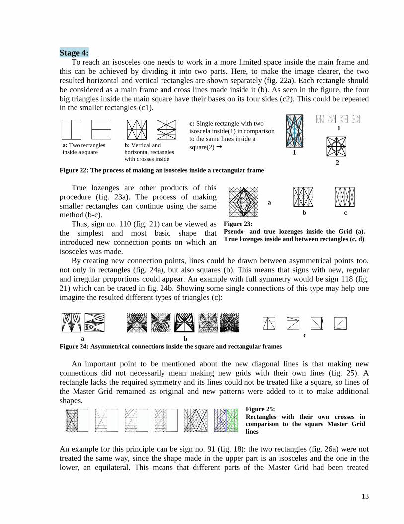
Stage 4:
To reach an isosceles one needs to work in a more limited space inside the main frame and
this can be achieved by dividing it into two parts. Here, to make the image clearer, the two
resulted horizontal and vertical rectangles are shown separately (fig. 22a). Each rectangle should
be considered as a main frame and cross lines made inside it (b). As seen in the figure, the four
big triangles inside the main square have their bases on its four sides (c2). This could be repeated
in the smaller rectangles (c1).
c: Single rectangle with two
isoscela inside(1) in comparison
to the same lines inside a
square(2) 1
1
2
a: Two rectangles
inside a square
b: Vertical and
horizontal rectangles
with crosses inside
Figure 22: The process of making an isosceles inside a rectangular frame
True lozenges are other products of this
procedure (fig. 23a). The process of making
smaller rectangles can continue using the same
method (b-c).
Thus, sign no. 110 (fig. 21) can be viewed as
the simplest and most basic shape that
introduced new connection points on which an
isosceles was made.
a
b c
Figure 23:
Pseudo- and true lozenges inside the Grid (a).
True lozenges inside and between rectangles (c, d)
By creating new connection points, lines could be drawn between asymmetrical points too,
not only in rectangles (fig. 24a), but also squares (b). This means that signs with new, regular
and irregular proportions could appear. An example with full symmetry would be sign 118 (fig.
21) which can be traced in fig. 24b. Showing some single connections of this type may help one
imagine the resulted different types of triangles (c):
a b c
Figure 24: Asymmetrical connections inside the square and rectangular frames
An important point to be mentioned about the new diagonal lines is that making new
connections did not necessarily mean making new grids with their own lines (fig. 25). A
rectangle lacks the required symmetry and its lines could not be treated like a square, so lines of
the Master Grid remained as original and new patterns were added to it to make additional
shapes. Figure 25:
Rectangles with their own crosses in
comparison to the square Master Grid
lines
An example for this principle can be sign no. 91 (fig. 18): the two rectangles (fig. 26a) were not
treated the same way, since the shape made in the upper part is an isosceles and the one in the
lower, an equilateral. This means that different parts of the Master Grid had been treated

14
differently or, to put it another way, the inventor was free to work with different grids or frames
side by side. Here we combine the two (fig. 26): if we divide the main square (a) into four
smaller ones (b), each of these can be viewed as a main square (c1, c2). The inventor was free to
work inside each of them or a combination of two or more, as the structure of the upper part of
sign 91 belongs to stage 4 and the lower part to the previous stages (d).16
a b c1 c2 d
Figure 26:
Using two types of triangles inside the
Master Grid
Group 8: Signs 121 and 122 resemble group 5 but with oblique sides (fig. 27). 122 has been
documented on the SKS brick inscription and though incomplete, its overall shape can almost be
distinguished. The main body is similar to sign 121. The oblique sides can well be placed on the
lines of smaller grids (fig. 28).17
The upper lines follow the main Grid lines. This is also the case
with the cross inside sign no. 122. In the lower left corner of sign 122, there is a short oblique
extension with its left part parallel to the oblique line of the Master Grid but the right part
connected to the main body along a line which cannot be superimposed neither on the Master
Grid lines nor the other one; this is a new connection. Sign no. 123 has similarities to 121 but
with different dimensions. The latter lacks the left oblique line and the interior lines of the
former seem to have been pulled out and placed under the base.
121 122 123
Figure 27:
LE signs of group 8
a b 65. hapax SKS31. 1 98. hapax Figure 28: Pentagons
One may assume the following stages for the change of a triangle to a honeycomb sign:
a b1,2 c d1,2,3 e1,2,3
Figure 29:
Probable changes from a
triangle to honeycomb. b, d and
e are depicted in different sizes
Sign 124, which is Meriggi’s hapax 86, looks like a distorted lozenge with its axis turned along
an oblique line. To find out how it was made, we have to try different ways: In the first case (fig.
30a), the midline of the Grid passes from the two ends of vertical lines, as the sign indicates too,
and all the lines lie well on the Master Grid. In b1-2 made inside three squares, the two vertical
lines have one end on the midline. In this case too, all lines follow Master Grid’s. If we change
the proportions (c), the base grid has to be changed. With this method line E does not follow the
16
Compare the lower half of 26d to figure 23a. 17
Imagining new squares or rectangles is what I have called “free connections”, since for every such connection,
one is free to consider a new background shape.

15
lines of the two horizontal rectangles, but lies on the Master Grid line. Again, this is a free
connection.
a
124
b1 b2
c c
Figure 30:
Three ways for reconstructing
sign number 86
86. hapax
Group 9: Circles
Group 9 consists of circles. Drawing circles should have been an important development
which increased inventor’s abilities in creating new shapes.18
Some LE signs have dots on or beside their lines. As previously mentioned, based on their
positions, one can deduce that dots appeared on line intersections (fig. 31a). An enlarged dot
makes a circle which in its smallest size is encompassed by the closest lines making pseudo-
lozenge, itself encompassed by the closest lines making a square (b). So, size of a circle depends
on the surrounding lines from inside the smallest pseudo-lozenge (c1) and square (d1) to the
largest ones (c3/4, d3/4). The center of a circle can be matched with an isosceles too (e1-2).
a b c1 c2 c3 c4 d1
d2 d3 d4 e1 e2
Figure 31: Dots on line
intersections (a). Circles inside
the smallest and largest
pseudo-lozenges, squares (b-d)
and triangles (e)
As there are several squares and pseudo-lozenges in the Master Grid, circles can be drawn in
all of them. Circles can be overlapping (fig. 32a) as well as tangent (b-d) and in different sizes.
a b c d Figure 32: Overlapping circles inside squares
(a). Tangent circles inside squares (b-c) and
pseudo-lozenges (d). Basically circles appear in
two types in the Grid: 1) bolds which are enlarged
dots on line intersections, 2) non-bolds or circles
freely drawn inside other shapes.
Some LE circle signs have a free space below for another smaller circle. Taking into account
the symmetry that governs the Master Grid and considering that the frame square diameter
passes right through the central dot, the smaller circle too should be drawn inside a pseudo-
18
See also figure 6o.

16
lozenge not a square. For these two circles be tangent, the bigger one should be on 2&2 or 3&3
lines to leave a wider space between the two circles.
LE signs 125 to 132 are circles. Hinz has another circle sign in his list which is included in
fig. 33, but not numbered.
125 126 127 128 129 130 131 132 List of
Hinz 102. hapax 101. hapax 83. hapax 37 37.a SKS42. 4 38 100. hapax
Figure 33: LE signs of group 9
Group 10: Circle surroundings
Here are included signs that have circles as their bases but with different treatments implying
that it is not the circle itself that becomes the sign but parts of it or the space inside or around it
maintaining its circumference. These signs are classified in two groups:
a1 a2 b c1 c2 c3 c4
d1 d2 d3
Figure 34:
Single, double, tangent and overlapping circles used for
making signs
A) Single circles: In this case, every part of the circumference of a circle could be used to be
worked on: half, quarter, or smaller parts (fig. 34a1-2).
B) Two or more circles: Three methods seem to have been at work with more than one circle: 1)
They were juxtaposed at various intervals dictated by the Grid (examples are shown in fig. 34b).
The inventor could work within the space between the circles keeping their circumferences as the
two sides of the sign. 2) Tangent circles placed side by side in various positions were the second
type. Their circumferences could be followed in curved (c1-2) or wavy lines (c3-4). 3)
Overlapping circles, again at different intervals, were other alternatives. Closed spaces inside the
these circles were used to make signs (d1-3). There is no need to emphasize that the resulted
shapes are numerous.
Lines in the interior space of the overlapping circles could be drawn in two ways: 1) with two
movements, putting the pen on the tablet drawing the left side up to down and then removing the
pen and starting the right side from the first point up and in the same direction; 2) Drawing the
whole shape with one movement, up-down-up or vice-versa without removing the pen.
Depending on the speed of writer, the latter would gradually change the original shape to an
independent geometric form: an ellipse which being cut at different intervals in one half, makes a
parabola.19
One can draw ellipses and parabolas in different sizes as long as the frame is
19
Parabola has a more precise definition in geometry. Here the word is used in a very general sense.
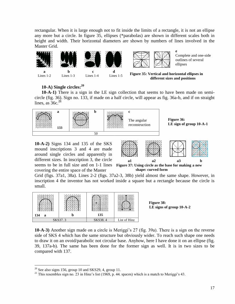
17
rectangular. When it is large enough not to fit inside the limits of a rectangle, it is not an ellipse
any more but a circle. In figure 35, ellipses (*parabolas) are shown in different scales both in
height and width. Their horizontal diameters are shown by numbers of lines involved in the
Master Grid.
a Lines 1-2
b Lines 1-3
c Lines 1-4
d Lines 1-5
e
Complete and one-side
outlines of several
ellipses
Figure 35: Vertical and horizontal ellipses in
different sizes and positions
10-A) Single circles:20
10-A-1) There is a sign in the LE sign collection that seems to have been made on semi-
circle (fig. 36). Sign no. 133, if made on a half circle, will appear as fig. 36a-b, and if on straight
lines, as 36c.21
a
133
b
c
The angular
reconstruction
Figure 36:
LE sign of group 10-A-1
50
10-A-2) Signs 134 and 135 of the SKS
mound inscriptions 3 and 4 are made
around single circles and apparently in
different sizes. In inscription 3, the circle
seems to be in full size and on 1-1 lines
covering the entire space of the Master
a1 a2 a3 b Figure 37: Using circle as the base for making a new
shape: curved form
Grid (figs. 37a1, 38a). Lines 2-2 (figs. 37a2-3, 38b) yield almost the same shape. However, in
inscription 4 the inventor has not worked inside a square but a rectangle because the circle is
small.
134 a b 135
Figure 38:
LE signs of group 10-A-2
SKS37. 3 SKS38. 4 List of Hinz
10-A-3) Another sign made on a circle is Meriggi’s 27 (fig. 39a). There is a sign on the reverse
side of SKS 4 which has the same structure but obviously wider. To reach such shape one needs
to draw it on an ovoid/parabolic not circular base. Anyhow, here I have done it on an ellipse (fig.
39, 137a-b). The same has been done for the former sign as well. It is in two sizes to be
compared with 137.
20
See also signs 156, group 10 and SKS29, 4, group 11. 21
This resembles sign no. 23 in Hinz’s list (1969, p. 44. spaces) which is a match to Meriggi’s 43.

18
10-B) Overlapping circles: 10-B-1) In Meriggi’s list, hapax sign 103 is made on the lower half of two overlapping circles
(fig. 40a-b) as shown in fig. 34d2 too. Another sign that has appeared on SKS2 is no. 139. At
first glance, it may seem as two curved lines getting close to each other like (139
b), but it is actually made on the upper half of two overlapping circles with the side lines
continued to the base of the Grid (139a). Hapax 66 has the same structure. I have reconstructed it
on a parabola as well.
The two sidelines following their background lines, are closer in sign 141(a-b)(fig. 41). Hapax
73 in Meriggi’s list is another example of overlapping circles but in this case not 2 but probably
4 (142a). To examine another possibility, this sign is made on two parabolas as well (142b). The
angular version makes the picture clearer (142c).
10-B-2) Four almost similar signs not existing in Meriggi’s list have appeared in the SKS
inscriptions. Although basically curved-sided, these have in some cases irregular sides getting
even close to straight lines. Sometimes part of one side is clearly angular, so that one doubts
whether it is a lozenge. This group too is the product of overlapping circles but probably
indicates an archaic view towards the shape. When following the interior lines of two the
overlapping circles, if one loses the right sight to the circles’ circumferences and follows the
straight lines of the Grid as well, the result becomes an irregular shape which can have various
appearances as is clearly evidenced in the SKS inscriptions. To avoid several overlapping circles,
I have reconstructed these signs inside ellipses (fig. 42). One can observe the irregularity of the
interior lines in each separate case. In two cases, I have added an empty ellipse to give a clearer
picture of the lines behind the signs.
136 a b c 137 a b
Figure 39:
LE signs of group 10-A-3
27 SKS35. 4
138 a b 139 a b 140 a b
Figure 40:
LE signs of group 10-
B-1
103. hapax SKS39. 2 66. hapax
141 a b 142 a b c
Figure 41:
LE signs of group 10-B-1
18 73. hapax

19
143 SKS 2 SKS 3 4 144 145 146 147
Figure 42:
LE signs of group
10-B-2
SKS41. 2, 3, 4 SKS44. 4 SKS43. 4 SKS42. 2 SKS45. 1
In a number of inscriptions, some circles are not fully round as they should be. Wet clay and the
deformation of signs may not always be the reason. They might have undergone the same
procedure of following lines of the Grid.
10-C) Juxtaposed circles (/ellipses): 10-C-1: The simplest signs of this group with circular or ovoid/parabolic bases are numbers 148
and 149. In fig. 43, these signs are shown on both circles and ellipses as their bases and in two
sizes. In the first case, the circular base makes a closer shape to the original. In sign 149a, the
lower case is closer to the original and thus is smaller than a semi-circle. This may be called a
hyperbola.
148 a b 149 a b
Figure 43:
LE signs of group 10-C-1
44.a 44
10-C-2: Other signs with similar structures but using the space in between circles or
ellipses/parabolas are numbers 49, 63, 70 and 92 in Meriggi's list. In fig. 44, they are
reconstructed using both circles and ellipses/parabolas. In order not to neglect any possibility, the
angular shapes are also added.
The circular base of sign 150(a) resembles more to the original but for sign 151 the parabolic
base (b) seems to be qualified. As for signs 152 and 153 only the ovoid/parabolic base is in
accordance with the original form.
150 a b 151 a b c 152 a b c 63. hapax 49 92. hapax
153 a b c d
Figure 44:
LE signs of group 10-C-2
70. hapax
10-D) Three LE hapax signs, numbers 76, 88 and 91 in Meriggi’s list, are different from the
entire collection. They look more like paintings than geometric patterns. No. 154 rejected any
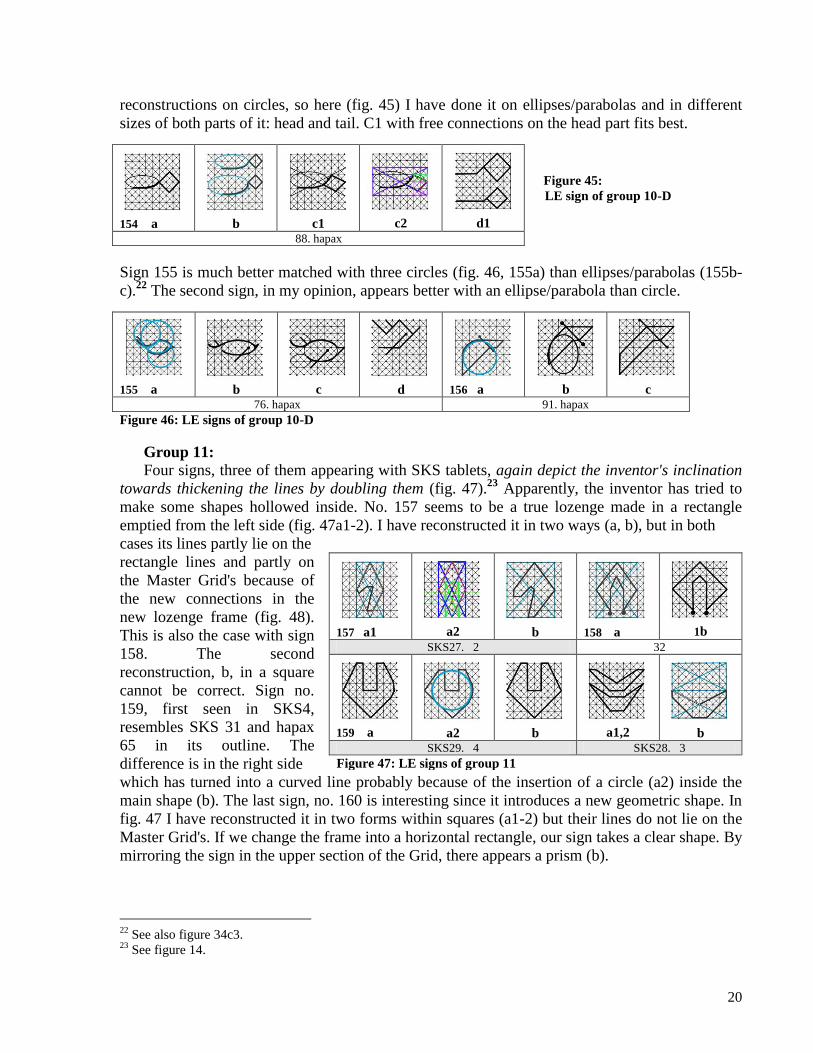
20
reconstructions on circles, so here (fig. 45) I have done it on ellipses/parabolas and in different
sizes of both parts of it: head and tail. C1 with free connections on the head part fits best.
154 a b c1 c2 d1
Figure 45:
LE sign of group 10-D
88. hapax
Sign 155 is much better matched with three circles (fig. 46, 155a) than ellipses/parabolas (155b-
c).22
The second sign, in my opinion, appears better with an ellipse/parabola than circle.
155 a b c d 156 a b c 76. hapax 91. hapax
Figure 46: LE signs of group 10-D
Group 11:
Four signs, three of them appearing with SKS tablets, again depict the inventor's inclination
towards thickening the lines by doubling them (fig. 47).23
Apparently, the inventor has tried to
make some shapes hollowed inside. No. 157 seems to be a true lozenge made in a rectangle
emptied from the left side (fig. 47a1-2). I have reconstructed it in two ways (a, b), but in both
cases its lines partly lie on the
rectangle lines and partly on
the Master Grid's because of
the new connections in the
new lozenge frame (fig. 48).
This is also the case with sign
158. The second
reconstruction, b, in a square
cannot be correct. Sign no.
159, first seen in SKS4,
resembles SKS 31 and hapax
65 in its outline. The
difference is in the right side
157 a1 a2 b 158 a 1b
SKS27. 2 32
159 a a2 b a1,2 b
SKS29. 4 SKS28. 3
Figure 47: LE signs of group 11
which has turned into a curved line probably because of the insertion of a circle (a2) inside the
main shape (b). The last sign, no. 160 is interesting since it introduces a new geometric shape. In
fig. 47 I have reconstructed it in two forms within squares (a1-2) but their lines do not lie on the
Master Grid's. If we change the frame into a horizontal rectangle, our sign takes a clear shape. By
mirroring the sign in the upper section of the Grid, there appears a prism (b).
22
See also figure 34c3. 23
See figure 14.

21
Pseudo-lozenge True lozenge a True lozenge b True lozenge c
Figure 48:
Pseudo- and true lozenges in
square and rectangles
respectively
To prove the cradle of a script, evidence from other fields than mere corpus of texts can be of
enormous assistance.
The two cemeteries of MahtUt ÃbAd and RIg AnbAr were plundered during the years
2000/2001. In 2002/2003 archaeological excavations started at the South and North Konar
Sandal mounds as well as the above mentioned cemeteries. Local villagers, disturbing the graves
of a people who had created one of the most sophisticated cultures of the ancient world, dug out
thousands of invaluable objects which subsequently were sent to other countries to appear in
museums and private collections. Later, some objects were returned to Iran and studied by the
head of the archaeological team and his colleagues. The result of their first studies was published
as a catalogue of the Jiroft objects (Madjidzadeh, 2003). Researchers were astonished by the
beauty of art and the high level of technology used in their manufacture.
One of the most beautiful objects published in Madjidzadeh's book
is a cylindrical vase made of chlorite and with an architectural
representation (pic. 1). As there appeared similar examples of this vase
with more or less the same representation, it was suggested by the
excavator that this should have been a building of central importance to
the site, probably a religious and a governmental center as well.
Picture 1: Chlorite vase,
Jiroft (Madjidzadeh, 2003,
67)
Obviously, the importance of this building lies in its geometric
patterns. A closer observation guides us to the point. The building has a
round plan skillfully reflected in the overall design of the vase (pic.2).
The exterior wall has four gates, each having a tripartite entrance and
side walls moving inwards in three successive intervals which makes
the entrance somehow hidden from the outsiders' view. The upper part
Picture 2:
The exterior
entrance of the Jiroft
vase building (idem.)
of the entrance is similarly made but in upwards curvature. This plan
can still be seen in the Iranian architecture. The façade above these is decorated with semi-
circular patterns. The recessed wall between the four gates is decorated with triangular elements
at the top. The inner parts are more elaborately designed (pic.3). The interior gates resemble the
exterior ones in their general plan with the difference in the doors which here are not plain but
decorated with hatchings and rectangular patterns above them. The uppermost decorations are
also vertical rectangles and triangles. The same elements can be seen on the sides of smaller
doors(?) or (pseudo-?)windows(?). These have another floor above them with similar
architectural elements and decorations. There is a decorative band above these all.
Picture 3:
The interior parts of the
Jiroft vase building (idem.)

22
All the patterns on this building can be reconstructed in our Master Grid. The only difference
would logically be an increase in the number of lines necessitated by the larger surface inside
which to work. So we increase the number of lines from 9 to 25 or 1-12 0 12-1.
Drawings represented in Madjidzadeh's book are
in negative; if changed to positive, we can more
clearly distinguish the geometric shapes. The simplest
pattern, that is a square or rectangle with a diagonal
cross inside, can be seen in the decoration above the
a1 a2 a3 b1 b2
Figure 49: Cruciforms as decorative
elements
interior gate and between and on the two sides of
doors(?) and windows(?). Here both square and rectangular
patterns are presented in negative and positive (fig. 49).
Other decorative elements are hatchings (see also fig. 9) on
the interior entrance (fig. 50a). Unlike other parts that most
probably had been unbaked brick-works, these could well have
been woven fibers. The decorative band at the topmost part of
the building is reproduced here in both negative and positive
a b c
Figure 50:
Hatchings (a) and the decorative
patterns on top of the Jiroft vase
building (b, c) (b, c). This seems to be a more elaborate design in comparison
to others. It is repeated all around the topmost part of the building and the reason could have
been its higher place giving the structure uniformity to look bigger in size from the outside.
The plan of the entrance is conceived by drawing two
ellipses, one almost circular pattern for the upper part (see also
fig. 35e) and six vertical lines for the gate sides (fig. 51a). b
depicts how several such decorations are made in successive
sizes. The angular reproductions of the exterior and interior
entrances as well as side parts are shown in fig. 52.
a b
Figure 51: Plan of the two entrances
Archaeological excavations at the SKS
mound brought to light remnants of a circular,
thick wall, recessed in unearthed parts which
considering its location and size, soon became
the main candidate for the outer wall of the
building in question. The giant, painted clay
statue of a deity discovered during the
excavation season of 2006-2007 in a room at
the topmost part of the mound inside the wall,
proved that this building had also been of
religious importance, otherwise it could hardly
a
b c d
Figure 52: Geometrical reproductions of the Jiroft
vase building. Decorative band(a). Buildings b and
c are drawn wider to show the details
be realized why it appeared on precious objects
buried with the dead.
Even today one can repose in a Kantuk on the South
Konar Sandal mound slope and watch the ancient mound
from behind the same geometrical patterns that have
survived the millennia. Reeds woven in crosses make a
round wall over which stands a dome-like cover stabilized
by ropes tied in diagonal crosses (pic. 4).
a b
Picture 4: Jiroft Kantuk

23
Jiroft art is evidence to the existence of an ancient geometrical school in the Halil Rud basin,
not only as a source for the invention of writing systems, but mathematical calculations,
architectural designings and other intellectual achievements. Master Grid had been of numerous
functions and a source for inventions in different fields. Here some cases are mentioned:
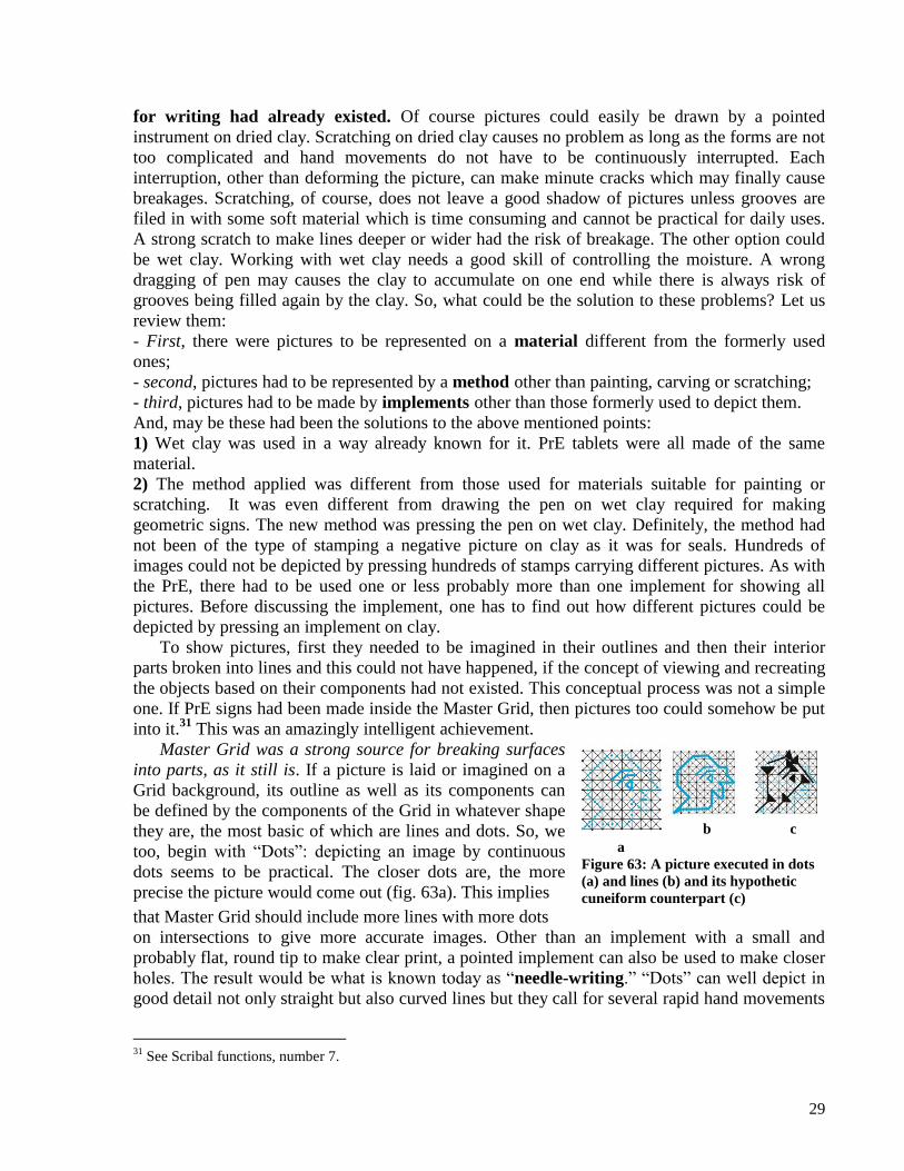
1] Scribal functions: As previously discussed, Master Grid was a source for inventing signs to communicate
concepts of everyday life.24
Dictated by economic purposes, the system should have been under
the monopoly of temple men or the governing class -both the same for millennia to come- from
its early days till much later. The instrument for using the Grid was a creative mind and strong
imagination to design patterns inside a simple but extremely productive grid. The method was to
determine which line/s and dot/s should be chosen and in what combinations. This could be done
with or without external inspirations. But the important question is: Was it under certain rule/s or
was it freely performed? I started my work by systematically joining together lines which finally
formed a grid to be used as a source for making further signs. This means that I directed my
work from one, two and three lines towards a grid, and once the grid appeared, there came to
existence a source for creating innumerable shapes for different purposes. Probably before that,
the number of shapes had somehow been limited. Signs to be placed in the very primitive stages
may hint to the stages that passed (fig. 53).
Figure 53:
Some very simple LE
signs
Can we possibly suppose that such a Grid had existed in its totality from the very beginning
when the inventor attempted to invent signs? Was it that somebody somehow found this
mysterious Grid somewhere and started to make signs in it? This is against the evolutionary
process of human mind. We should look deep into the past to find the most primitive forms when
man first attempted to materialize his concrete thoughts. This had not been the same with his
incredibly developed cave paintings based on his appreciable patience in watching his natural
models in thousands of years. This one was his own creation. As previously mentioned,
geometric shapes can be traced back in ancient petroglyphs25
and also later in pottery designs.
If this had been the real procedure, then there should have been an order in the invention of
signs. This implies that we must be able to put the signs in a chronological order according to
their structures. That does not mean that every single, simple sign should have a time interval
with the next and a little more complicated one, but that probably with a change in the
geometrical attitude of the inventor, there had been a cease and then proceeding to the next stage.
To reject this, we find us obliged to suppose that very simple signs, as those shown in fig. 53,
could have been invented along or even after the more complex ones. As far as geometrical rules
are concerned, this is not logical. It is not possible to jump to a “trapezoid” without knowing
anything about “line and angle.” One can work strictly within a defined framework or combine
24
Considering the productivity of the Master Grid in creating shapes, it was most probably regarded as sacred and
thus a means of communication with gods via symbols. Sacredness of “image” and “script” has continued up to the
present in different cultures. 25
For information on a collection of very interesting Iranian petroglyphs, see Naseri Fard, 2009.

24
two or more of them at the same level and simultaneously, but doing it with no knowledge of the
rules governing each separately, is nothing but chaos. This is definitely not the case with the LE
system.
Considering that our Grid had been a source for creating innumerable shapes, one important
factor in distinguishing different groups of signs -from the simplest to the most complicated-
would be the high number of specimens at hand to work on. 103 LE signs are not enough for our
purpose, though Jiroft findings have yielded some very simple forms that have filled in few of
the empty boxes of our puzzle. So, we have to turn to another known Elamite script with deeper
roots in time: Proto-Elamite. Discussing PrE in detail, though basic for the study of LE, is not the
purpose of this article, since it calls for another work analyzing all of the signs based on the same
method, but here I give some hints.
According to Meriggi, LE has some signs in common with PrE. In the second volume of his
book, he has compared about 57 LE signs with PrE (Meriggi, 1974, 8-24). Some of these are
exactly the same, like his numbers /LE 1b=PrE 298/, /4=308a/, /5=218/, /6=219/, /7=229/, /8=220/
etc. Some signs have relative resemblance, like /LE 13 and PrE 252g/, /15 and 263/, /77 and
256/, /95 and 206/ etc. In page 5 he has classified the signs in two main groups: 1) open signs (1-
105), 2) closed signs (106-340), itself with subdivisions (106-138) (140-213) (218-259) (260-
283) (284-340) and (341-391). There are 393 signs and their sub-forms in his list.
In my opinion, there is nothing in the LE sign collection that may separate it from PrE other
than the function of signs which caused a decrease in their number as a consequence. I believe
that these two writing systems belong to the same geometric system discussed above. So, the
high number of PrE signs can be of enormous assistance in finding the basic forms or, in other
word, to help complete our puzzle. In some cases, however, where PrE lacks an intermediate
from, it is LE that comes to assist.
Here I make some very general remarks on PrE:
1 2a 2b 3 4
LE
LE
PrE 9d
PrE 19a
PrE 11a PrE 6
E=A1B1 PrE 9
(see Note 2)
PrE 35 B2C1
................................................................................................................................................................... .............................................................................................
1 2 3 4 1a ? 1b 2 3 4
PrE 7 A2B1
PrE 7a A3B1
PrE 7b
PrE 7c ? LE LE PrE 204f LE PrE 04g
................................................................................................................................ ...................................................................................................................................................................
1 2 3 4
1 2
LE PrE 11 PrE 13 PrE 20 PrE 14 PrE 14c ............................................................................................................................. ... .........................................................
Figure 54: Some Pr-/LE. signs in a progressive sequence of invention. (For PrE signs see Meriggi, 1974, pp. 8-
24 ). Serial numbers in boxes show the sequence.

25
1) Signs were all made in the same Master Grid, so the basic features are: lines -straight and
diagonal- and dots/circles and whatever shape which is in connection with these, as discussed
before.
2) Signs were made in progressive procedures from the simplest to the more complicated. It is
here that both Pr.- and LE may cooperate to complete the picture. Some examples are presented
in fig. 54. Here signs are put in order based on their structures as having 1 to 6 or more vertical
and horizontal lines.26
All the specimens needed are not necessarily among the present sign collection. Some empty
spaces may remain in our picture. This can be due to two factors: either we have to wait for new
discoveries and new signs to appear or we can postulate that some signs sometime in their very
early stage of usage had been substituted by other forms. Despite this, there are many signs in the
PrE collection that can be put into our scheme.
3) The inventor made use of every possibility within the Master Grid.
This means that each line or dot can be viewed separately and worked
on independently (fig. 55). When the grid materializes, it is this view
that makes every part a movable and removable unit.27
4) Signs were made in different sizes regarding their width or height,
depending on the dimensions of chosen limits. Some very general
possibilities are shown in fig. 56.
As previously mentioned, the intervals between lines directly
affect the appearance of a sign. PrE signs 29, 29a, 29b and 29b’ are
good examples (Meriggi, 1974, 9). Therefore, it should not be
surprising to see several signs with the same shape but different
dimensions. Whether they had the same graphical value or not is
another matter.
Figure 55:
Viewing the Grid with all
of the lines and dots as
separate components to be
worked on.
a b c
Figure 56:
Open and closed
rectangles in different sizes
and patterns
d e f
5) Once a rule was fixed, that is when the inventor pictured a geometrical shape in the Grid -as
square, rectangle, circle, lozenge, triangle etc. - he felt free in connecting every dot to every other
dot within the new limits. That is the reason why in a single sign lines may seem to belong to
two or more geometrical shapes, if not based on completely free connections. Of course, this
does not mean going towards chaos, but only considering the grid as a multipurpose device with
defined and undefined alternatives. For instance, sign no. 102e is a beautiful star which we still
draw in the same way as our ancestors dictated. We can draw it 1) in the Master frame (fig. 57a,
b, d, e, f), 2) considering the symmetry of the lines of two rectangles (c), or 3) inside a pseudo-
lozenge (and not merely a vertical rectangle as seen in fig. 57-102e). All these are stars, but the
last one has the appropriate proportions we would evaluate as best. There had been a judging
26
Sign 2b in the first row is interesting as it best confirms figure 11 2&8 (see also figure 1B2). 27
See the section on Recreational functions.

26
mind behind the figures. In the same frame we can reach sign 102d’ as well whereas 102, 102a’
and 102c can be made both inside the Master Grid and the pseudo-lozenge. A similar harmony as
in sign 102e is seen in the beautiful sign of 138b made in four overlapping circles inside four
squares.
a b c d e f PrE 102e PrE 102d’
PrE 102c PrE 102a’ PrE 102 PrE 138b
Figure 57:
Finding appropriate proportions among different
possibilities
6) An interesting feature of the PrE is the use made of dots by the inventor. Dots appearing on
the intersections of lines, despite their small sizes, were used as numerals (fig. 58).28
Here, I have
presented them in their smallest size at the center of the Grid as well as the corresponding largest
size to make the image clearer.
e:
Eight main
possible
divisions of a
dot/circle
f: Complete and
horizontal/vertical semi-
dots in the Master Grid
a:
Horizontal
division
b:
Vertical
division
c:
Diagonal /
Division
d:
Diagonal \
division
Figure 58: Possible dot divisions in the PrE
7) PrE signs 316, 336 and 342 are as if an amateur hand has made the Grid a shadow in the
background and drawn paintings. Though still inside the limits of the Grid, these signs are not
comparable with a sign like 349 which is indeed a piece of art. The same pattern can be seen
on an object from Jiroft (Madjidzadeh, 2003, 109).
8) We might be able to trace back in the PrE what is known as cuneiform script. Many of us may
have asked ourselves: Where did cuneiform script come from? Why and how should a sign look
like what we know as a cone? Was cuneiform the ultimate stage of a pictographic system, and if
so, how did the original pictures with their whole collection of different lines break into their
components and then presented by cone-like strokes? Had cuneiform script already existed as an
independent system and came to be used because of a necessity? If this had been the case, then
two questions need to be answered: What was the origin of this script and wherefrom and how
did the idea of it being used for this purpose come? In my opinion, ancient geometry can present
the answer.
28
See Mathematical calculations.

27
After finishing the reconstruction of LE signs based on the methods presented, I started
searching for some information on the very subject of “Ancient Geometry” and was acquainted
with a very interesting book which I received two weeks later: "The Secrets of Ancient
Geometry- And Its Use" by Tons Brunés first published in 1967 and reprinted in 2006.29
In this
book, in addition to many interesting points about its main subject, the role of geometry in the
ancient and medieval architecture, reader can find some general information on the importance
and extent of use of geometry in the ancient world too. Chapters 17 and 18 of the second volume
were of special interest to me. In chapter 17, starting with the development of numerical systems
among different cultures of the ancient world, the author has suggested a geometric diagram -
exactly like our Master Grid- as the source for the invention of the signs known as “cuneiform”,
that is the simple vertical cone-like sign and another sign known as winkelhaken. Though
Brunés' deduction is based on the mere appearance of the cuneiform signs, yet it is very
interesting.30
This is exactly what I came to while working with the Master Grid. If we go back
to stage 4, fig. 22, we can easily distinguish the shape in question (also fig. 59). The difference,
in the simplest aspect, is in the reasoning for the shape of winkelhaken. In my opinion
winkelhaken -though its original shape may not exactly have been what is shown here in fig. 59
(see fig. 67 and the related discussion)- calls for working in a rectangle not, as Brunés has
discussed, a square. Another very important difference is that the writer, based on the main
subject of his book, that is architecture, has given no hint of the historical background of the
cuneiform signs and has only reconstructed them inside the diagram.
a:
Base Grid for
cuneiforms
Figure 59:
Cuneiform signs in a rectangular
framework. Winkelhakens are shown
in two sizes. See also fig. 67b. b:
Winkelhaken c:
Vertical and horizontal
cuneiform signs
Returning to the PrE, there is an important feature hidden in signs 1, 2, 9, 10, 11 or 12, not to
mention others. These are actually tiny lines with very small dots in the middle or at the two
ends. In some cases, these dots are so small as if lines have just a little thickened. These may be
nothing but the small dots on the intersections of lines of the Grid. These clearly show inventor's
attempt in making signs from the simplest and most primitive shapes at hand: a line and the dot
on it. In fig. 60, I have shown some of the possibilities in making such signs. Horizontal or
diagonal forms can also be imagined.
29
Unfortunately I did not receive the new edition but 1967’s. 30
In the same chapter (pp. 190-194) Brunés has put the Indo-Iranian numerals 0, 1, 2, 3, 4, 5, to 9 in the same
diagram. I did the same with New Persian numerals too. This way it becomes clear why we have no problem with
different styles of writing numerals, as round, angular etc. As long as numerals are made into the diagram with
which we are familiar, there will be no problem in decoding them. Brunés has used the same diagram for Phoenician
letters (pp.195-228) and it is strange why there should not be any reference to his interesting work in the sources
allocated to the history of writing.

28
a b c d e f g h i
j k l
a: Lines in the same size; one dot
b: Lines in different sizes; one dot
c: Lines in different sizes; two end
dots
d: Lines in different sizes; two dots
e: Lines in different sizes; three dots
f: Lines in different sizes; four dots
g: Lines in different sizes; five dots
h: Lines in different sizes; six dots
i: Lines in different sizes; seven
dots
j: Lines in different sizes; eight dots
k: Lines in different sizes; nine dots
l: Lines in different sizes; one dot
Figure 60: Dots on lines. Note the change in the number of lines with different dots
Signs 19, 20 and 36 in Meriggi's list are easily found in the grids of fig. 60: e, c, and a,
respectively. Numbers 67 and 57a have free dots and 57, 58 and 59 have horizontal lines with
dots. No. 21 is an example of diagonal lines with dots.
These signs are good examples of how the two basic elements
became models for cuneiform signs. We can view the problem from
another angle too: dots could be replaced by triangles immediately
attached to the vertical lines. If we divide into two parts a dot or a
circle at the top of a vertical line [+], these forms appear:
+and+ (fig. 61a). Pseudo-lozenge [ ] can be divided into
smaller parts too: +{and +} (fig. 61d). This latter in its turn
a b c d
Figure 61: Three ways for
making new signs. b and d
are more qualified to be
called cuneiforms.
can make new divisions [ ]: +,+[=] {and also=} (61b), and still smaller
ones:+,+[=] (61c). The two components appear in rectangles. Of course, not all of
the forms in fig. 60 have evidence in the cuneiform writing systems of the entire ancient
Near/Middle East but many of them have real examples. A dot at the end of a line means an
inversed cuneiform which is not as common as others (fig. 62).
a
b
c
d
e
Figure 62: Cuneiform
signs in different
numbers and positions
outside and inside the
Master Grid (a-d).
Comparison of the LE
sign no. 21 (fig. 14)
with its cuneiform
counterpart (e).
Now, we can pose the old question: When was the cuneiform invented? Was it after the
inventor had created hundreds of signs -some of them very complicated indeed- that he returned
to the simplest elements when the time came to invent a new writing system? My answer is: this
invention could have been happened at a very early stage and both systems of geometric and
cuneiform could have moved side by side. Do we know what the original function of cuneiforms
had been? The oldest specimens show signs that some of them can be followed back to their
original pictographs. If pictures, formerly painted, scratched or carved on materials as wood,
bone, stone etc, were to be represented on a different material as clay, then there should have
appeared the necessity of a change in the method of representation. This means that using clay
29
for writing had already existed. Of course pictures could easily be drawn by a pointed
instrument on dried clay. Scratching on dried clay causes no problem as long as the forms are not
too complicated and hand movements do not have to be continuously interrupted. Each
interruption, other than deforming the picture, can make minute cracks which may finally cause
breakages. Scratching, of course, does not leave a good shadow of pictures unless grooves are
filed in with some soft material which is time consuming and cannot be practical for daily uses.
A strong scratch to make lines deeper or wider had the risk of breakage. The other option could
be wet clay. Working with wet clay needs a good skill of controlling the moisture. A wrong
dragging of pen may causes the clay to accumulate on one end while there is always risk of
grooves being filled again by the clay. So, what could be the solution to these problems? Let us
review them:
- First, there were pictures to be represented on a material different from the formerly used
ones;
- second, pictures had to be represented by a method other than painting, carving or scratching;
- third, pictures had to be made by implements other than those formerly used to depict them.
And, may be these had been the solutions to the above mentioned points:
1) Wet clay was used in a way already known for it. PrE tablets were all made of the same
material.
2) The method applied was different from those used for materials suitable for painting or
scratching. It was even different from drawing the pen on wet clay required for making
geometric signs. The new method was pressing the pen on wet clay. Definitely, the method had
not been of the type of stamping a negative picture on clay as it was for seals. Hundreds of
images could not be depicted by pressing hundreds of stamps carrying different pictures. As with
the PrE, there had to be used one or less probably more than one implement for showing all
pictures. Before discussing the implement, one has to find out how different pictures could be
depicted by pressing an implement on clay.
To show pictures, first they needed to be imagined in their outlines and then their interior
parts broken into lines and this could not have happened, if the concept of viewing and recreating
the objects based on their components had not existed. This conceptual process was not a simple
one. If PrE signs had been made inside the Master Grid, then pictures too could somehow be put
into it.31
This was an amazingly intelligent achievement.
Master Grid was a strong source for breaking surfaces
into parts, as it still is. If a picture is laid or imagined on a
Grid background, its outline as well as its components can
be defined by the components of the Grid in whatever shape
they are, the most basic of which are lines and dots. So, we
too, begin with “Dots”: depicting an image by continuous
dots seems to be practical. The closer dots are, the more
precise the picture would come out (fig. 63a). This implies
a
b c
Figure 63: A picture executed in dots
(a) and lines (b) and its hypothetic
cuneiform counterpart (c) that Master Grid should include more lines with more dots
on intersections to give more accurate images. Other than an implement with a small and
probably flat, round tip to make clear print, a pointed implement can also be used to make closer
holes. The result would be what is known today as “needle-writing.” “Dots” can well depict in
good detail not only straight but also curved lines but they call for several rapid hand movements
31
See Scribal functions, number 7.

30
which can be energy and time consuming for long inscriptions. This method is best suited for
short inscriptions as well as making images on hard materials as metal. It was in use till later
periods in Iranian art. If such a background is not to be accepted for the needle method, then
there should be searched an origin for it.
By using the other basic shape that is “Line”, the space needed for several dots
(/circles/holes) can be covered by a single pressure of stylus on clay. So, a picture turns to a set
of straight lines which is more economic but loses some details and quite rapidly gets far from its
original identity and this was exactly what happened with the first pictographs written in
cuneiforms (fig. 63b-c).
3) What was the implement to be used for such writing and how was it shaped? I suppose that
the pen or the so called “stylus” to make pictures on clay came out of the Grid itself. Obviously,
dots or small holes could be made by any sharp object with round tip but the procedure of
making a pen for such writing might have been more precise and systematic. Based on the
Master Grid, there could be at least four basic alternatives for the cross section of a stylus: 1)
circle, 2) square, 3) rectangle, and 4) triangle including: a) big isosceles which is half a square,
and b) small isosceles which is one forth a square.32
For making a stylus these shapes had to
become solids. Moving the bases vertically generates cylinder from circle, square prism -and
if cut short, a cube- from square, rectangular prism from rectangle and triangular prism
from triangle. Cylinders, rectangular and triangular prisms could well be
used as stylus, and apparently the first two had actually been used in the
ancient PrE and Sumerian tablets. The two ends of these solids are flat.
For keeping the form but controling the size of the cross section without
making any changes into the body of the shaft, a very intelligent
procedure was applied: by vertically pulling out the central dot of the
a b c
Figure 64: Change of
a square to a pyramid
section and placing it right above the center, some other forms appeared
(in fig. 64 the process is shown for a square). Circle turned to cone , square to square pyramid
, rectangle to asymmetric rectangular pyramid and triangle to triangular pyramid .
Obviously, the diameter of the base and the distance at which the central dot is placed affects the
ultimate form.
By the two above mentioned procedures joining together, each solid could have its original
section but a different protruding tip (fig. 65). Cone and pyramid tips could be cut at different
intervals and yield flat surfaces with varying circumferences. Each cross section is actually the same geometric
shape as the base but in smaller dimension.33
Diminishing the size of a circle inside the Grid
from its largest scale to the smallest, truely ends
in a dot but other shapes end in the smallest
Figure 65: Different sections for circular and
square base pyramids corresponding shape possible in the Grid which is obviously
not a dot. The section could also be made obliquely which calls for a different view towards the
Grid and the geometric shapes coming out of it. Free connections may justify these. So, each of
32
Other forms were possible too, as parabolas or hexagonals etc. 33
Moving each section down to the base creates several solids one inside the other as the ground plan of the
Ziggurat of Chogha Zanbil depicts.

31
these solids could be used as stylus to make impressions on wet clay depending on their sections
and also the way they were held in hand (fig. 66).34
It seems that rectangular, triangular and
circular sections were among the first to be used. Up to the
present, the exact shape of the cuneiform stylus has been
partially conjectured.
Other than the simple wedge which could be pressed in
vertical as well as horizontal and oblique positions, another
print known as winkelhaken is also attested. The truth that
Figure 66:
Some possible
sections for stylus
this sign could have been made with the same stylus as for the simple
wedge and by merely turning it upwards-right, and also its later
appearance in the written records, does not put in shadow the
importance of the reason and process of its invention. What indeed
did inspire the inventor to make a winkelhaken? Probably the shape
that appeared between two oblique cuneiforms (fig. 67a) could have
a b
Figure 67
been the source.35
Another more probable option might be a shape like fig 67b which allows both
simple cuneiform and winkelhaken be made with one and the same stylus. The latter appears
with slightly upward-right movement of the stylus. This would imply that the cuneiform sign b in
fig. 61 could have been the original form.
4) Other than signs, formats of flat tablets were also dictated by the Master Grid, as square ,
rectangular , circular , parabolic , elliptic etc. Some of these could be made as
solids too, like conical cylindrical, hexagonal etc. up to the cylinder of Cyrus the Great which
actually is an elliptic solid cut at the two ends.
2] Recreational functions:
Brunés’ book has another subject in common in chapter 20: “Origin of Chess.” With the very
first look at the Master Grid (see also fig. 32), anybody would recall a chess board. Chess must
be much older than what is stated about it in the Pahlavi literature: a game brought to the
Sassanian Iran as a sign of the Indian supremacy of mind challenging Iranians’ as well as seeking
remedy of paying tribute. After the Iranian great sage, Wuzurg Mihr, King XusrO AnOSag
RuwAn’s Prime Minister, had given three days of time to other Iranian noblemen to reveal its
secrets and they were unsuccessful, himself did it conveniently. Then, Indians or people of the
Sind valley received in return from Wuzurg Mehr another game to decode named backgammon
which they failed to after forty days of fruitless effort and therefore, found themselves obliged to
pay multiple tribute. The point inherent in this story might be that Iranians had been those who
had mastership over both games. The two cultures being neighbors with common traditions is a
point not to be ignored. Chess then up until recently in contemporary societies has been a game
of intelligentsia and in the hands of those who knew its secrets. These two lead us to another
function of our Grid.
The mysteriously productive Grid pouring out shapes mostly lacking in nature, not only
bestowed on man a more systematized and stabilized vision of the world around, provided him
with instruments for a better dominance over nature’s harsh rules -improved architecture being
only one- and gave him signs that being encoded by its inventor, prevented any stranger from
34
Even today we can trace back our cored pencils with varying sections (, , ) to this very structure. 35
See also SKS28 (?).

32
entering his ever-growing world of information, but had other gifts too. It gave the inventor/s the
opportunity out of serious calculations into a more recreational world. Master Grid generated
different games, mostly based on boards and beads. In addition to strengthen mental abilities,
these games created a friendly atmosphere for comrades to sit, think, play, boast and have fun.
But whatever came out of this mysterious board had one thing permanent with it: challenge of
mind.
Playing with such Grid means that rules should be set for “lines and dots” in the first place
and probably other shapes hidden in it, in the second. The Grid could be viewed in two ways:
either the images of its components be imitated on whatever material by drawing, or be made in
material. So, if one decides to draw them, what is needed is a plain board of appropriate material,
a writing implement, and rules for how and where to draw what. The most rudimentary of this is
a game still popular in Iran called “Khatt o Noqteh” or “Line and Dot.” Due to its simplicity, it
is known as children’s game but even adults may be willing to play it as it is amusing and a
pleasant reminder of their childhood. It is an elementary game and here is exactly
where its importance lies. It is the simplest game two persons can play with a piece
of paper and two pens, if not one. With no paper and pen, it can easily be played
with a piece of hard object on soil. The famous X/O is another very simple Grid
game based on filling square cells with cruciforms () and circles () along Figure 68:
X/O game horizontal, vertical and diagonal lines (fig. 68). Crossword puzzle in which the whole
Grid cells are filled with graphical signs to make words, is a more improved game which
combines the two scribal and recreational functions together, and probably this is the secret of its
universality; it combined doing exercise on graphical signs, conjecture on lexicon, making a
collection of related words and fun all together.
As already mentioned, Master Grid had been viewed another way too. Lines and dots had to
be either fixed or moving. A rapid look at dots as the simplest repeating components of the Grid
and following them in different directions gives the viewer a sense of motion. Needle writing is
itself a result of such view. Of course drawing a line from one point to another would not be
possible without moving either. If, in a shape like ┫, a point is imagined at the meeting spot of
the two lines, then moving from that point further ahead to the right can mean moving the dot to
another spot in the right side making the shape like this: ╋.36
Probably, another very simple
game had been moving dots along the lines in vertical, horizontal, diagonal or any other direction
which lines and rules dictated. One cannot move the dots in mind, so the whole Grid had to be
materialized to be touched in hand and reflect the movements. Other than perishable materials, a
tablet of wet clay for drawing lines could be the first step. Baking made it more durable for
several games. Now, what about dots? Drawing them on clay only made some round shapes or
holes, so one had to make real pieces to play the role of dots. They had to be placed either on line
intersections, inside squares, pseudo-lozenges, triangles or big circles (see fig. 32). Based on the
present evidence, we may accept that placing simple square, triangular or circular objects in
corresponding holes may have been amongst the most archaic choices. In time, better materials
than clay were used both for boards and markers, such as precious stones, hard woods, ivory etc.
Such games have appeared in archaeological findings in a vast area from India, Iran, and
Mesopotamia to Egypt (pics. 5, 6). Jiroft too has yielded few specimens. Here, boards are made
of chlorite and their shapes range from flat rectangular objects to more artistic works as eagles,
36
See figure 14, 6-7.

33
scorpions or mythical creatures. The numbers of holes on boards are different like 36 (pic. 5a),
21(b, c), 20(d) and 16(e).37
The most elaborate board game may have been Chess. The
number of markers, 16 for every player, is the same as the
number of squares in a line of our Grid. Brunés has shown
that the three directions for movements on the chess board are
all along the main lines of the diagram, that is straight
(vertical and horizontal), diagonal linked with squares, and a
mixture of verticals and horizontals along the diagonal line
which is actually one side of the big central isosceles. It is
definitely not accidental that chess and today’s
backgammon38
are usually made together on two sides of a
wooden box. Chess goes side by side with backgammon, a
board game played in various versions and in many countries.
Its ancient versions had different appearances with different
rules.
a
b
c d e
Picture 5: Jiroft board games (a-e)
(Madjidzadeh, 2003, 108, 120, 130,
135)
In 1926-27 the most ancient 20-squares board game with its markers were discovered in
grave 789/pg of the Royal Cemetery of Ur and dated to between 2550 to 2400 BCE. (pic. 6a).
Following that, four other boards were also found there. In 1977 the first board game measuring
33/4cm12/7cm6mm along with 60 objects were discovered in grave IUP731 of Shahr-e
Sukhteh, a Bronze Age site near Zabol in the Sistan province of Iran. The report of the discovery
was first published in 1982 in an article by Piperno-Salvatori (1982, 79-85) (pic. 6b).39
It has
been dated to about 2500 to 2300 BCE, the third phase of settlement at Shahr-e Sukhteh which is
almost contemporary with the Ur board. Shahr-e Sukhteh’s board is decorated with engraved
intertwined serpent having its tail in mouth and closely resembles a small table-like board from
Jiroft (pic. 5a). Konar Sandal mounds and Shahr-e Sukhteh had been in close cultural
relationships and their discoveries are evidence to the existence of an ancient board game
tradition in eastern Iran.
a b
Picture 6:
a) Board game from the Royal Cemetery of Ur (British
Museum), b) board game and dies from Shahr-e Sukhteh (National Museum of Iran)
There are several other traditional games especially played by the villagers of Iran that are based
on movements following geometric patterns. Discussing games is not the subject of this article.
Here, I only give the plan of a popular game called “Dis/Duz Bazi”/“Markers game” as an
example (fig. 69a). It is in two versions, one with 9 dots and the other 17. It is played by two
37
d with 20 holes can be compared with the “Royal Game of Ur” and the Aseb board of Egypt. Aseb was
sometimes put on the other side of Senet or “Game of Thirty squares” boards. 38
The most famous board game in Iran is “Nard”. The word “Nard” is the developed New Persian form of Sassanian
NEw-(ArdaxSahr>)Arda(x)SIr “ArdaSIr the Brave”, thus called to celebrate the braveries of ArdaSIr I, the great King
of Kings of Iran. Western backgammon covers a wider range of board games. 39
The last report of this discovery can be found in Piperno-Salvatori, 2007, 287-295 (board in pages 294-295). Dr.
Seyyed Sajjadi has presented the report of this board in an independent article (2009a, 162-177, photos in page 323).
The photo can be found in his 2009b, 733 too. Bowl number 42 with the animation scene had been found in this
very grave (see Artistic Functions).

34
persons each having eight “Dis” or markers to
place on dots in a straight line while preventing
the other from doing the same. The one who has
finally only two markers in hand or no room to
move is the loser. Sometimes, it is this game
which is made on the other side of a chess board
in Iran. Children’s hopping grids without a stone
a1: 9 dots a2: 17 dots b
Figure 69:
The geometric plan of Dis Bazi (a1, a2) and grid
hopping (b) or preferably with a flat round stone for being moved in cells can be traced back to our Grid too.
As mentioned earlier, a characteristic of these Grid games was that they were brought from
the abstract to the real. If the first stage had been drawing lines and dots on clay or on the ground
and then came the next by making them real in material, so what could be the other stage? The
answer would be moving it still closer to the real world by throwing life onto the board. Humans
could either appear on a big board-like pattern drawn on the ground and move along defined
lines or make a ball or balls of dot/s and move it/them, or both.40
Many games, old and modern,
come into mind. Master Grid had definitely other functions too.
3] Artistic functions: The most ancient animation discovered from
Shahr-e Sukhteh could not have appeared without
any understanding of “motion” and previous
experiences for depicting it (pic. 7) (Piperno-
Salvatori, 2007, 287-295 bowl: 289-290, also
Seyyed Sajjadi, 2009a, 169, photo in p. 7).41
Picture 7: Animation scene painted on a bowl
from Shahr-e Sukhteh, Sistan, Iran (National
Museum of Iran)
The perception of “something which is here in this spot can be and is there in that spot too” -
what every component of the Grid reflects- may first be understood by that thing being existent
at every intermediate space in between the two spots which is the same as the thing being
repeated in every intermediate situation. Each such situation can be viewed as a static picture
with no difference with the one before and after it no matter where its location throughout the
space between the two spots is. From among all the repeating situations, the first and the last are
most important because these are the two limits of what may be called the motion of frozen
pictures (fig. 70a-b). When time comes that other moments than the start and the end should also
draw attention, then immediately leaves the concept of “having no difference with the previous
and the next”. So, “the thing”, that is “the same thing” should somehow appear differently in
every sequential situation to have its own momentary identity. And thus appears animation, the
materialized narration with its emphasis not being restricted to the first and the last moment but
40
The concept of movement exists in the Persian word “bAzI kardan” “to (do) play”. The first part of this verb,
“bAzI” , derives from the Pahlavi word “wAzIg” (play, game) based on a root with two forms: 2uAz- “to play, contend,
(passive?) to lose (in games)” and uaz-“to move, carry, drive (a chariot): to fly” (Cheung, 2007, 429-433). The
forms wazIdan/waz- “move, blow (of wind)”, 1wAzIdan/wAz- “move, carry away, fly” and
2wAzIdan/wAz- “play” are
also attested in the book Pahlavi (MacKenzie, 1971, 89). In the Sassanian book of XusrO KawAdAn ud REdag, the
word for “dance” is pAy wAzIg “foot play” or “foot movement”, which has survived in some of the Iranian dialects.
In Persian “bAzI kardan” is also used for dramatic arts as is the case with the word “play” in English. 41
A petroglyph very much similar to the Shahr-e Sukhteh animation scene has been discovered in the Teimareh
Mountains of Khomein in the Central Province of Iran (see Naseri Fard, 2009, Ibex images: folio 2, image 2).
Systematic temporal and spatial study of these petroglyphs has not yet been conducted in Iran. (A.Moqaddam,
Spring of 2012)

35
extended to the entire sequence: the beginning, duration and completion of an action. The
important point is that each image should represent the immediate starting moment after the very
last moment of the previous image (fig. 70c). This is what Shahr-e Sukhteh images depict and is
different from other known cases of the ancient world.
a b1 b2 b3 b4 b5 b6 c
Figure 70: Dots conveying movement of repeating pictures (a-b). Lines in pictures conveying animation (c)
Obviously, animation needs an apparatus to show the images in motion and Shahr-e Sukhteh
images on a single vessel may not be qualified to be called one, but the fact is that such a scene
on a vessel that can be turned round in front of fixed eyes, somehow do convey a rudimentary
sense of motion. Probably, the choice of a bowl for such scene had not been coincidental and its
turning on the pottery wheel had been the past for this vision.
How could Master Grid be irrelevant to pictures, if cuneiforms for depicting “one moment
pictures” had been invented inside it?
Movements in different directions inside the Grid and their varying measures could have
various reflections. What tickles mind is music. Have the regular structure, harmonious shapes
and their up and down replacements had such an impact on the human mind to trigger such great
achievement as systematic musical composition along with the designing of instruments or
redesigning of older instruments to play it? If so, stringed instruments would have been among
the first choices. Vertical, horizontal and oblique lines having turned to strings of appropriate
material and framed in different formats determining their lengths, produced different sounds in
vibrations. In a simple square or rectangular frame (fig. 71a), strings were of the same length, so
the only factor to minutely differentiate the sounds was the spot of plucking -though the main
sound was made in the midline of wires- whereas a curve (previously bow instruments?) or
triangle conveniently cut the strings at different lengths and so, caused different sounds to be
produced (fig. 71b-g, j-k, m-n). These were harps. Harps, mentioned by the Sumerians as the
most ancient instruments, had been among the objects discovered from the Royal Cemetery of
Ur (2450 BCE).42
Images of harps and other similar instruments are seen on rock reliefs and seal
impressions in Elam as well as Mesopotamia.43
They continued to be played in Iran for centuries
and -along with win and winkannAr- appeared as the first in a list of the musical instruments
played in the Sassanian court mentioned by the Page in the story of "XusrO KawAdAn ud REdag".
42
"One the most striking elements of Sumerian culture is the sudden appearance about 2600 B.C. of instruments
(harps and lyres) so elaborate that they presuppose a long previous development of which no trace is left."
(Duchesne-Guillemin, 1981, 287) 43
1] "Harps were depicted in Iran from at least 3100 BCE to 1600 BCE, a longer period than elsewhere. Arched
harps were shown on seals, being played vertically at Chogha Mish (3300-3100) and Susa (2750-2600), but
horizontally in Shahri Sokhta (3000-2300 BCE) and in south-eastern Iran. In the 2nd
millennium BCE the focus
shifted to the Elamite region in western Iran. As in Mesopotamia, Elamite harps were angular, but the latter were
smaller. … Judging from the presence of large harp ensembles (larger than those of Mesopotamia), Elam had a
major harp culture." {de Vale et al., "Harp" in Grove Music Online}. 2] "In Mesopotamia the earliest known
evidence for such instrument is slightly later (c3000 BCE), but given the uncertainties of dating and the scarcity of
the material, it is impossible to determine in which region this harp appeared first." {Lawergren et al., "Iran: i)
Arched harps" in Grove Music Online}.

36
a b c1 c2 d e f g h
i j k l m n o p q
Figure 71: Harps in different shapes and with different numbers of strings (a-o) (see also fig. 24). Base
patterns of a percussion (p) and a wind instrument (q)
The number of strings, their intervals and later probably, the diameter of strings could be
changed according to the musical rules. Another step would have been changes in the points of
connections which created new string lengths (fig. 71h, i, l, o). An important improvement
happened when the Grid itself became the back support to strings to which they had been tied, so
the length of each string could be controlled and changed by pressing the finger on it at different
intervals. These spots were actually dots on line intersections. The quality improved with part of
the back support changing to a hollowed box to resonate sounds. Probably the older wind and
percussion instruments would also evolve to more systematically manufactured objects by being
remodeled inside the Grid. In a Grid every movement is defined according to its location. A
round surface is understood by several concentric circles, and its divisions -like a clock- by the
sectors, as a flute is defined by the intervals of its open and closed holes (p-q).
No wonder if all these had been achieved in temples and by the (king-)priests who sought for
more influence on their followers. A strange, charming sound coming out of an instrument not
working in the hands of ordinary people meant possessing a sacred talent and mysterious power
bestowed from Heaven.
How could a piece of music not be captured
and written down with such a precise and well-
defined instrument at hand? A composer could
perpetuate his composition by putting it on a
tablet.44
It was possible by using conventional
signs specifically invented for this purpose or the
signs by which the language was written, as the
acrophonic signs later used by the Sumerians. It
is not unlikely that in the earliest stages signs
from inside the Grid, as squares, circles, triangles
etc had conventionally been used for this
purpose. The most elementary notation for lire
(fig. 71c1) would be names for strings (= lines),
Figure 72: Hypothetical divisions of wires in a
primitive wire instrument. Names for strings in
symmetric (A: A-E, B-left, B-right …) and sequential
arrangements (A to I). 1-9: names for dots on strings for
intervals.
1
1 2
1 2 3
1 2 3 4
1 2 3 4 5
1 2 3 4 5 6
1 2 3 4 5 6 7
1 2 3 4 5 6 7 8
1 2 3 4 5 6 7 8 9
El Dl Cl Bl A Br Cr Dr Er
A.. B. C. D.. E. F.. G. H. I...
as /A-B-C-D-E-F-G-H-I/, and numbers for dots, as
/1-2-3-4-5-6-7-8-9/ (fig. 72).45
44
"The earliest clay tablets with writing use a round harp as a pictogram" (Kilmer, "Mesopotamia: 2. Pre- and
Proto-literate periods" in Grove Music Online). 45
There can be seen some degree of resemblance between the modern system of musical notation and components
of the Master Grid, as movements of vertical/oblique lines or dots/circles on horizontal parallel lines. The
resemblance of LE sign 30 (Meriggi’s 30), 31 (Meriggi’s 29) and 36 (Meriggi’s 29a) to some of the signs in the
modern system is sobering.

37
Based on the present evidence, it is supposed that -even in Mesopotamia and despite the
discovery of huge archives of cuneiform tablets from the Akkad and new kingdoms periods,
among which there are lexical texts with specifically technical musical lexicon, as terms for
stringing, tuning and playing string instruments- musical knowledge had been transmitted orally
up to the Babylonian time.46
But this may be altered by the future discoveries. The situation is
more difficult in Iran because here the number of written documents is very limited. SKS3 tablet
contains repeating collections of signs (fig. 73).47
Is this likely to be a piece of music or
song/hymn? It had been written on a clay tablet and then fired in kiln to be deposited in archive.
Why should such a short document be written in relatively large signs and on a tablet with a size
not appropriate for daily use, and then fired? The reason could be that the words or signs(?) had
taken fixed forms worthy of being preserved somewhere in order to be used on different
occasions.
b a
Figure 73: Rearrangement of the SKS 3 units in the position from boustrophedon to left-to-right
(a) and right-to-left (b)
4] Mathematical calculations: A measuring instrument as ruler is the simplest to be imagined inside the Master Grid (fig.
74a). Lines were undoubtedly counted and their intervals determined for drawing Grids of
specific functions. Making a precise straight line measuring tool called for a Grid with closer line
intervals. Shahr-e Sukhteh has provided us with an example (pic. 8). This is a 10cm ruler with
half millimeter divisions made of ebony (CHN, 25 January 2005. Picture in Seyyed Sajjadi,
2009b, 733).
One of the most primitive but still widely used devices for doing mathematical calculations is
“abacus” or “counting board/frame”. The ancient specimens could have been tablets with painted
vertical lines or carved grooves between which beads made of different materials moved. So,
46
Kilmer, "Mesopotamia: 5. Old Babylonian periods, 8. Theory and practice" in Grove Music Online. The Nippur
tablet (ca. 2000 BCE), the Sippar tablet (ca. 1600 BCE) and the famous Assyrian KARI-4 (ca. 800 BCE) all contain
cuneiform signs which seem to be musical directories. 47
A study of the four SKS Mound inscriptions by the writer will appear in a separate book.

38
after lines had been deepened to grooves and before changing to framed rods or wires, it was a
“counting board”.
Again, the structure directly recalls Master Grid. The
basic components have always been lines and dots (fig.
74b, also see figs. 32c, 58f) and specific rules for their
roles. Obviously, rules were different for different
functions and it was the extraordinary potentiality of the
Master Grid which enabled it to base such diverse
manipulations. As the vertical and horizontal lines inside
the Master Grid were used for measuring straight lines
in the form of ruler, dots on line intersections were
logically used for counting numbers. PrE inscriptions
are excellent evidences of this function.48
Through time,
dots were given conventional values to increase their
efficiency. This was a remarkable improvement. In its
early days, counting board was used to do simple
a
b
Figure 74:
a) Ruler inside the
Master Grid. b) Sketch
of abacus inside the
Master Grid
Picture 8:
Wooden ruler
from Shahr-e
Sukhteh
calculations as subtraction, addition, division and multiplication but in time developed to do
more complicated calculations as extracting square and cubic roots etc.
Master Grid had definitely more important mathematical functions than mere arithmetic.
Precise geometric circumference and area calculations were fundamental to a developed
architecture magnificently visible on Jiroft vase buildings. North Konar Sandal mound of Jiroft is
actually a huge three-storey mud-brick structure with the base platform measuring 400400m,
claimed by the excavator to be not only the largest but the oldest of the type in the ancient
Near/Middle East (Madjizadeh, 2003-2004, 9). On the other hand, another smaller but still
massive structure (base platform: 5635m) at Tepe Sialk of Kashan has also been nominated as
probably the most ancient of the region (Malek Shahmirzadi, 2002, 27-54). These two have
seriously challenged the old hypothesis of such constructions, renowned by the Sumerian word
“Ziggurat”, as having been originated in Southern Mesopotamia. Obviously, the question of the
Sumerians’ original home land is a very serious one.
Game boards should not be viewed as simple entertaining devices as they definitely had not
been so. Movements of markers on the board were determined by mathematical calculations at
different levels. PrE and LE signs are invaluable treasures that can guide us to a professional
society active in innovations. Few points are mentioned here:
Dice is a very interesting invention and subject of discussions since long time ago. It might have
come out of the Master Grid. This is again a matter of coming to the real from the abstract, so we
have to find traces of it in the Grid and try to materialize them. Dice is a guide or actually a
choice implement based on numbers. In ancient specimens, as Shahr-e Sukhteh’s dies depict,
these numbers are from 1 to 4, whereas in later ones -as today dies- they are from 1 to 6. But
these numbers might not have been the only options as we do not know what games existed and
called for what choices.
We start from number 1 and proceed up to 6. We need to find patterns in accordance with
these numbers in our standard Master Grid. The simplest concept would be 1 dot on a line and
48
The most ancient counting board dated to about 2700 to 2300 BCE was discovered from Sumer. One may see
some similarities to abacus in some of the Sumerian signs {Cf. probably signs 313, 324 (Labat, 1963, 36;
142,3 and 148,1)}.

39
then 2, 3, 4, 5 and 6 dots. The invention of devices for showing choices among these numbers
calls for the observance of the fundamental principle of “equality of incidence” implying that
when throwing a dice, each number should have the same chance to show as the other/s. So:
1) For the choice between 1 and 2, the device should be flat but can have various shapes like
square, rectangle, triangle, round etc. Each number is shown on each surface. Whatever the
shape would be, it has to roll well in the air in order to land well. Obviously, a round object rolls
best (fig. 75D). It is this round, bi-faced object which we call “coin” and still toss to choose one
or the other face. 2) For the choice among 1, 2 and 3, the device should be a triangular prism
with numbers made on its 3 surfaces not 5, that is on the shaft not the two ends (fig. 75E). A
triangular pyramid can be used too which has the profit of having no shaft but no chance of a
good roll either. 3) For the choice among 1, 2, 3 and 4, the device should be a square prism with
numbers made on its 4 surfaces not 6 (fig. 75F). 4) For the choice among 1, 2, 3, 4 and 5, the
device should be a pentagonal prism with numbers made on its 5 surfaces not 7 (fig. 75G). 5) For
the choice among 1, 2, 3, 4, 5 and 6, the device should be a hexagonal prism with numbers made
on its 6 surfaces not 8 (fig. 75Ha-b).
1 2 3 4 5678 a b 1 2 3 4
a
1 2 3 4
b
A] dots at
different
intervals
B] a: 1-4 dots (down). 1-6 dots
(up). b: 1-4, 1-6, 1-7, 1-8 dots
C] a:1 -4 dots on line
intersections. b: Dots in
rectangles
D] 1-2 dots.
Circles could
be tangent
E] 1-2-3 dots
a b a b c
d1,2,3
F] 1-4 dots G] a: dots at different intervals
and inside different frames. b:
1-5 dots
H] a: Comparison of 1-6 dots (left) with 1-5 dots (right). b: 1-6
dots. c: cubic dice (1-6 dots). d: unfolded cubic dies
Figure 75: Dice models inside the Master Grid
It may seem that making real objects of these models calls for each part being made
separately and then stuck together. This is not what happened because solids did not evolve
easily. Giving volume to a flat surface if not a line is a complicated process. Proto- and Linear
Elamite signs as well as SKS signs assist us to understand this.49
Before taking the shape of a
complete cube, dies had been of other shapes. Their construction had most probably passed these
procedures: 1) Sketching the shape on whatever flexible material at hand like a thin layer of wet
clay. 2) Changing the lines (fig. 75Ca) [see LE sign no. 2 as well as 126 = Meriggi’s hapax 101]
into areas by continuously doubling them (75Cb) [this technique can clearly be seen in some LE
signs, as no. 20 = Meriggi’s 39, 27 = Meriggi’s 56, 29 = Meriggi’s hapax 81 etc. See also PrE
signs 9d, 19a, 11a]. So, a line with a dot on it, as 75Ca1, would change to a flat rectangular area,
as 75Cb1. What is drawn is the plan of the entire shape altogether. By folding the whole shape
along its lines, a solid is born. A 3-columned rectangle easily changes to a triangular prism with
49
Reader should refer to the serial numbers of signs in the reconstructions in this article.

40
1-2-3 dots (75E) [see signs 43 and 44 (and SKS 12, 13). These two clearly show sketches for
such solids]. A 4-columned rectangle turns to a square prism with 1-2-3-4 dots (75F). A 5-
columned rectangle changes to a pentagonal prism with 1-2-3-4-5 dots (75G). And finally, a 6-
columned rectangle turns to a hexagonal prism with 1-2-3-4-5-6 dots (75H).50
These could have
been among the original dies as some of them -like Shahr-e Sukhteh’s 4-numbered dies- have
been discovered in ancient relics. But still another great invention happened: instead of the
hexagonal prism, the rectangular prism was cut short to equal sides and the resulted cubic device
was used with its entire 6 sides for the six numbers and the best roll (75Hc). Its sketch in the
Grid is intelligent (75Hc). It can be a T (cf. PrE sign no. 9) or a cross which is freely numbered
from 1 to 6 (fig. 75Hd).
Patterns of dies with 1-2-3 and 1-2-3-4 dots (fig. 75E-F) resemble PrE signs 14 and 14c
and the arrangements of lines in both are strange reminders of the KhayyAm Triangle (fig. 76).
a
b c d
1
1 1
1 2 1
1 3 3 1
1 4 6 4 1
1 5 10 10 5 1
Figure 76: 4-numbered dice(a), PrE signs 14(b) and 14c(c), KhayyAm Triangle(d)
Certainly, geometry and mathematics had numerous other functions.
What is known today as Medical Engineering could be one of the most
sophisticated. In 2006 there was found in grave no. 6705 of Shahr-e
Sukhteh a female skeleton, 28 to 32 years of age, in the left eye socket of
whom was laid a half-spherical artificial eye ball measuring 2.961.5 cm
in diameter and radius respectively, dated to about 3000-2900 BCE. It was
fixed against the head by a thread passing through the holes drilled to either
side of the object. Eight deliberately hollowed golden (or silver?) wires
Picture 9:
Artificial eye ball
from Shahr-e
Sukhteh
inlaid in superficial grooves running between the small circle at the center and the outer part
probably functioned as capillaries to maintain the moisture (Seyyed Sajjadi-Costantini, 2008).
This masterpiece of medical engineering is an object with a geometric plan exactly similar to fig.
58e. Such an artifact could not have been invented, if a high level of medical, geometric and
mathematical knowledge had not existed.
For the present and till more excavations are conducted in the eastern regions of Iran, one
should be careful with identifying Susa or the western and southwestern Elamite realms, as the
cradle of the so called Proto-/Linear Elamite writing system. The discovery of hundreds of PrE
inscriptions in Susa may not be an indisputable evidence for assuming it its place of invention.
Though Elamite culture has been traced in vast regions of the Iranian plateau, but with every new
discovery in the eastern parts more light is shed on the lost but highly flourished cultures of these
regions; cultures whose important roles in the evolution of the high civilizations of southern
Khuzistan and Mesopotamia may be buried under the heavy dust of time.
50
A closer look at the LE signs reveals that some may indeed have been flattened solids. Sign no. 34 (= Meriggi’s
hapax 94) turns to a square pyramid and no. 106 (= Meriggi’s 10a) becomes an incomplete triangular prism when
folded.

41
A simple comparison between this system and that of the eastern neighbors’, the Indus people,
gives it more independence. Sumerians’ cultural and scribal achievements are far from being
ignored by anyone, but what are important about the SKS mound inscriptions are the simple
forms of the new signs and their assembling in single tablets. It is an undeniable fact that the
number of inscriptions discovered in Iran is very limited but regarding the richness of the
archaeological sites of this part of the Middle East -especially its eastern regions which are
archaeologically young- it is necessary to do more research before any deduction is made on the
role of the Iranian lands in the cultural developments of the region.
That the structure of the main part of the writing systems discussed is geometric, makes it
necessary that their origin, process of development and the reason of them being accompanied
with pictographic and cone-like signs be studied. The inventory of geometric signs of these
systems includes a spectrum of simple to complicated patterns which could not have been
without former evolutionary stages or the result of accidental, simple or aimless activities. As
mentioned, geometric patterns can be traced in the ancient petroglyphs in many parts of the
world.51
Though Iran may be among the countries with the highest number of petroglyphs,
systematic studies have not yet been started there.52
Till more discoveries bring forth further
51
Petroglyphs of the Paleolithic caves of Europe, especially France, have been studied more than those of the other
parts of the world. A recent study on 146 cave signs by Genevieve von Petzinger is available on
http://www.bradshawfoundation.com/geometric_signs/index.php. Representing relative chronological and statistical
information, she has classified the geometric signs in the following groups: 1. Aviform (from 12 out of 146 sites;
less than 10%). 2. Circle (20%). 3. Claviform (15%). 4. Cordiform, (3 sites). 5. Crosshatch (17%). 6. Cruciform
(13%). 7. Cupule (15%). 8. Dot (42%). 9. Finger fluting (15%). 10. Flabelliform (18%). 11. Half circle (18%). 12.
Line (70%). 13. Negative hand (15%). 14. Open angle (42%). 15. Oval (30%). 16. Pectiform (5%). 17. Penniform
(25%). 18. Positive hand (7%). 19. Quadrangle (20%). 20. Reniform (Rare). 21. Scalariform (3 sites). 22.
Serpentiform (7%). 23. Spiral (2 sites). 24. Tectiform (10%). 25. Triangle (20%). 26. Zig-zag (7 sites). 52
Unfortunately, many of the Iranian petroglyphs have been destroyed by nature and also human activities, but still
their number is considerable. Most of the petroglyphs have been discovered and introduced by Mohammad Naseri
Fard in the Teimareh Mountains of Khomein in the Central Province of Iran, his birth place and home. Though not
an expert of the field, he has bestowed many years of his life to them. The general themes of the petroglyphs
introduced by him are as follows: 1) Geometric patterns: Dots or cup marks: dispersed; in sequences; connected with
lines. Circles: simple; concentric; spiral; composite with underlines; with dots at the center. Lines: simple; parallel.
Grids. Triangles. Lozenges. Star-like figures. 2) Human figures; body members like palm. 3) Animal figures. 4)
Plants. 5) Objects including musical instruments as harps. 6) Ziggurat-like patterns. 7) Mythological creatures. Some
SKS mound inscriptions have yielded more signs
closer to the Proto- than Linear Elamite (table 2). Since,
in my opinion, the two discussed scripts are actually the
same with a shift in type and number of signs, and
considering the fact that more ancient layers of Konar
Sandal mounds are waiting to be revealed -not
mentioning other known and unknown sites of Great
Iran- we better reflect more on Professor Madjidzadeh’s
suggestion in calling these "*Proto-Iranian" scripts,
especially if the ancestor of cuneiform scripts too, is to
be sought in this system.
A number of the geometric signs in the Pr-/LE have
counterparts in the Proto-Sumerian as this writing system
is a mixture of pictographic and geometric signs as well.
SKS
inscriptions
SKS Sign
number
PrE sign
number
2, 4 8 6b
1 21 ? 57
1 23 ? 237a
1 24 227
2 25 261
3 28 ? 73g
2 30 265
2, 3, 4 33 129 Table 2: Similar signs of the SKS mound
inscriptions and PrE script
SKS signs 43 to 47, totally lacking in LE,
have counterparts in PrE in their general
patterns.

42
information, one would not be able to judge whether the geometric patterns of the ancient caves
and rock arts should be classified as (scribal) symbols or not; but the continuity of these patterns
in millennia and in different locations is certainly a sign of their importance as cultural elements.
When, at the end of the fourth and during the third millennium BCE some of these ancient
geometric patterns appear in accompany with a considerable number of other new and more
complicated figures, one can hardly categorize them as non-writing patterns or even void of
linguistic rules. Even centuries before, some of these patterns had appeared as decorative designs
on manmade earthenware. Undoubtedly, a certain pattern on a vessel had a cultural background
and was the manifestation of a specific thought. Someday, they may start to unfold and display
their creators’ minds.
The more recent tradition of writing on stone could not have been separate from making
prints on rocks in the remote past. In whatever method and with whatever meaning and purpose
these were on the way of the materialization of human mind and ultimately, invention of writing.
After thousands of years, the ancient tradition of making figures and patterns on stones and rocks
was never abandoned and, despite the invention of different writing materials, it continued to be
performed for reasons of which the long history could be the strongest. Interestingly, there can
be found in Iran in the same regions where petroglyphs are found, isolated short Sassanian
inscriptions and also Qor’anic verses.
To understand geometric writing systems some questions need to be answered, the most
fundamental of all might be: how did they evolve and what did they communicate in their
earliest days? Definitely, finding answers to these questions is most difficult, if not impossible.
For the present, one may hint to some points and pose a few additional questions.
If patterns of natural phenomena around Man had been his inspirations in imitating and re-
creating them, then how did human mind pass the borders of mere imitations -reflected in cave
paintings- and enter the world of linear patterns or probably symbols? Chronological dating of
paintings and geometric patterns of the European caves proves their very old age, if not
synchrony. When did these two ways of viewing the surrounding world diverge and how much
distant these two worlds of the real and conventional had been? Based on the present evidence,
one may come to the conclusion that cave paintings and geometric patterns went side by side
with the latter not having been developed from the first. If the realistic images had developed to
linear re-creations, this was exactly the same procedure that happened in the third millennium
BCE during which pictographs changed to cuneiforms, but another mechanism had been at work
because apparently, cave paintings and geometric patterns had different origins and were made
independently.
How could Man view the natural phenomena around him as integrated entities composed of
different parts and the potentiality of changing to shapes which, in spite of being relatively
different from the original, could represent those very phenomena? In other words, how could
Man distinguish the structural lines of the visible phenomena and separate them, and why should
he basically do such thing? If he made the image of his own hand , how did he come to the
figures are accompanied by others from different groups, as geometric patterns beside animal figures (Naseri Fard,
2003). When figures are made not only beside but inside each other, they are more likely to be ligatures. Such
patterns could hardly be void of symbolism.
Iranian petroglyphs should be studied according to their themes, styles, temporal and spatial distributions. Some
figures have parallels in other countries and some are practically universal. Few also seem to resemble some of the
PrE and LE signs (Ibid, inscriptions). Even one specimen seems to resemble SKS 17, but one has to study them in
detail before coming to any conclusions.
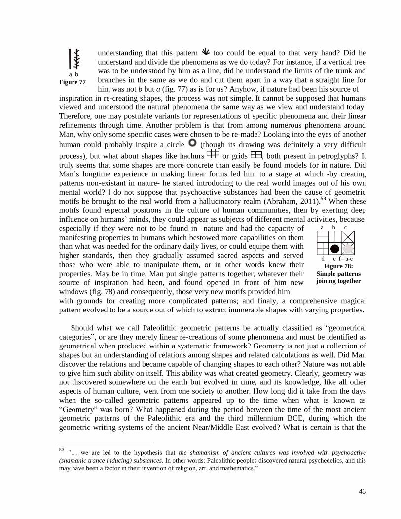
43
a b
Figure 77
understanding that this pattern too could be equal to that very hand? Did he
understand and divide the phenomena as we do today? For instance, if a vertical tree
was to be understood by him as a line, did he understand the limits of the trunk and
branches in the same as we do and cut them apart in a way that a straight line for
him was not b but a (fig. 77) as is for us? Anyhow, if nature had been his source of
inspiration in re-creating shapes, the process was not simple. It cannot be supposed that humans
viewed and understood the natural phenomena the same way as we view and understand today.
Therefore, one may postulate variants for representations of specific phenomena and their linear
refinements through time. Another problem is that from among numerous phenomena around
Man, why only some specific cases were chosen to be re-made? Looking into the eyes of another
human could probably inspire a circle (though its drawing was definitely a very difficult
process), but what about shapes like hachurs or grids , both present in petroglyphs? It
truly seems that some shapes are more concrete than easily be found models for in nature. Did
Man’s longtime experience in making linear forms led him to a stage at which -by creating
patterns non-existant in nature- he started introducing to the real world images out of his own
mental world? I do not suppose that psychoactive substances had been the cause of geometric
motifs be brought to the real world from a hallucinatory realm (Abraham, 2011).53
When these
motifs found especial positions in the culture of human communities, then by exerting deep
influence on humans’ minds, they could appear as subjects of different mental activities, because
especially if they were not to be found in nature and had the capacity of
manifesting properties to humans which bestowed more capabilities on them
than what was needed for the ordinary daily lives, or could equipe them with
higher standards, then they gradually assumed sacred aspects and served
those who were able to manipulate them, or in other words knew their
properties. May be in time, Man put single patterns together, whatever their
source of inspiration had been, and found opened in front of him new
windows (fig. 78) and consequently, those very new motifs provided him
a b c
d e f= a-e
Figure 78:
Simple patterns
joining together
with grounds for creating more complicated patterns; and finaly, a comprehensive magical
pattern evolved to be a source out of which to extract inumerable shapes with varying properties.
Should what we call Paleolithic geometric patterns be actually classified as “geometrical
categories”, or are they merely linear re-creations of some phenomena and must be identified as
geometrical when produced within a systematic framework? Geometry is not just a collection of
shapes but an understanding of relations among shapes and related calculations as well. Did Man
discover the relations and became capable of changing shapes to each other? Nature was not able
to give him such ability on itself. This ability was what created geometry. Clearly, geometry was
not discovered somewhere on the earth but evolved in time, and its knowledge, like all other
aspects of human culture, went from one society to another. How long did it take from the days
when the so-called geometric patterns appeared up to the time when what is known as
“Geometry” was born? What happened during the period between the time of the most ancient
geometric patterns of the Paleolithic era and the third millennium BCE, during which the
geometric writing systems of the ancient Near/Middle East evolved? What is certain is that the
53
"… we are led to the hypothesis that the shamanism of ancient cultures was involved with psychoactive
(shamanic trance inducing) substances. In other words: Paleolithic peoples discovered natural psychedelics, and this
may have been a factor in their invention of religion, art, and mathematics.”

44
highly developed architecture of the latter period in the ancient lands of the Near/Middle East
and North Africa alone can be a sign of a high level of geometrical and mathematical knowledge,
and such knowledge could not have emerged in a few centuries or millennia. This very aspect
would imply that geometric knowledge and patterns had deep roots in time and in the daily lives
of humans.
An understanding of the procedures during which geometric patterns evolve, the mechanisms
of their evolution and the position they occupied in humans’ minds may help decode their
meanings in later periods.
Tool-making was not possible without pre-planning. Therefore, we may start our research at
least from the days when Man started flaking his choppers to bring them close to the patterns
which had been shaped in his mind.
Bibliography:
1) Abraham, Ralph (2011), The Paleolithic Birth of Geometric Thinking.
http://www.ralph-abraham.org/articles/MS%23131.Caves/ms131.pdf
2) Basello, G.P. (2006), “The Tablet from Konar Sandal B (Jiroft) and its pertinence to Elamite
Studies”, www.elamite.net, 1-7.
3) Bork, F. (1905), "Zur protoelamischen Schrift," OLZ 8, 323-30.
4) Bork, F. (1924), Die Strichinschriften von Susa, Königsberg.
5) Cheung, J. (2007), Etymological Dictionary of the Iranian Verb. Brill (Leiden-Boston).
6) Dahl, J. L. (2005), "Animal Husbandry in Susa during the Proto-Elamite Period", SMEA vol.
47, 81-134.
7) Damerow, P. (2006), "The Origins of Writing as a Problem of Historical Epistemology",
CDLI, 1-10.
8) Damerow, P.-Englund, R. (rep. 2003), "The Proto-Elamite Texts from Tepe Yahya",
American School of Prehistoric Research 39 (Cambridge, MA).
9) Duchesne-Guillemin, M. (1981), "Music in Mesopotamia and Egypt", World Archaeology 12,
no. 3, Achaeology and Musical Instruments, pp. 287-297.
10) Englund, R. (1998), "Elam, iii: Proto-Elamite", in Encyclopaedia Iranica, vol. 8, 325-330.
11) Frank, C. (1924), Zur Entzifferung der altelamischen Inschriften (Berlin).
12) Glassner, J.J. (1998), "Les tablettes dites ’urukéennes’ de Sialk IV1", Nouvelles
assyriologiques brèves et utilitaires, 113.
13) Grove Dictionary of Music and Musicians (2001), eds. Stanley Sadie and John Tyrrell,
Oxford University Press (Oxford).
14) Hinz, W. (1962), "Zur Entzifferung der elamischen Strichinschrift," Iranica Antiqua 2, 1962,
1-21.
15) Hinz, W. (1969), "Eine neugefundene altelamische Silbervase", in Altiranische Funde und
Forschungen (Berlin), 11-44.
16) Hinz, W. (1971), "Eine altelamische Tonkrug-Aufschrift vom Rande der Lut",
Archaologische Mitteilungen aus Iran, Neue Folge (Berlin), 22-24.
17) Kilmer, A., "Mesopotamia", in Grove Music Online. Oxford Music Online. 12 April 2010.
<http://www.oxfordmusiconline.com/subscriber/article/grove/music/18485>.
18) Labat, R. (1963), Manuel D’Épigraphie Akkadienne (Signes, Syllabaire, Idéogrammes),
Quatrieme Edition, Imprimerie Nationale (Paris).

45
19) Lambert, M. (1974), "Deux textes élamite du IIIe millénaire", Revue d’Assyriologie et
Archéologie Orientale (Paris), 3-14.
20) Langdon, S. (1928), Pictographic Inscriptions from Jemdet Nasr, Oxford Editions of
Cuneiform Texts 7 (Oxford).
21) Lawergren, B., et al. "Iran." Grove Music Online. Oxford Music Online. 12 April 2010.
http://www.oxfordmusiconline.com/subscriber/article/grove/music/13859.
22) MacKenzie, D.N. (1971), A Concise Pahlavi Dictionary. Oxford University Press (London).
23) Madjidzadeh, Y. (1998-99), Nakhostin va dovvomin fasl-e hafriyyat-e bastanshenakhti dar
mohavvate-ye Ozbaki: Savojbolagh, Selsele gozareshha-ye moqaddamati, shomara-ye 1
(Tehran).
24) Madjidzadeh, Y. (2003), Jiroft, The Earliest Oriental Civilization, Cultural Heritage
Organization.
25) Madjidzadeh, Y. (2003-2004), Excavations At Konar Sandal, Jiroft, Halil River Basin
Project, Kerman Cultural Heritage Organization (Jiroft).
26) Madjidzadeh, Y. (2008), “Archaeological Project of the Halil Basin: A Legendary
Discovery”, Proceedings of the First International Conference of Archaeological
Research in Jiroft: 2004. Ed. Y.Madjidzadeh. Cultural Heritage, Handicraft and Tourism
Organization of Kerman Province (Jiroft), 29-52.
27) Malek Shahmirzadi, S. (2002), The Ziggurat of Sialk, Sialk Reconstruction Project, Report
No. 1, Iranian Cultural Heritage Organization (Tehran), 27-54.
28) de Mequenem, R. (1949), Épigraphie proto-élamite, Mémoire de la délégation en Perse 31
(Paris).
29) Meriggi, P. (1969) "Altsumerische und proto-elamische Bilderschrift," ZDMG Supplement 1,
156-63. 30) Meriggi, P. (1971), La scrittura proto-elamica, pt. 1
a : la scrittura e il contenuto dei testi
(Roma).
31) Meriggi, P. (1974), La scrittura proto-elamica, pt. IIa
: Catalogo dei segni (Roma).
32) Muscarella, O.W., "Jiroft and 'Jiroft-Aratta', A Review Article of Yusef Madjidzadeh, Jiroft,
the Earliest Oriental Civilization", http://www.bulletinasiainstitute.org/ Muscarella _
BAI15.pdf.
33) Naseri Fard, M. (2009), Iranian Petroglyphs (Ideographic Symbols), Author (Khomein).
34) von Petzinger, Genevieve (2012), Geometic Signs, A New Understanding.
http://www.bradshawfoundation.com/geometric_signs/index.php
35) Piperno, M.-Salvatori, S. (1982), "Evidence of Western Cultural Connections from a Phase 3
Group of Graves at Shar-i Sokhta", in H.-J. Nissen & J. Renger, eds., Mesopotamien und
Seine Nachbarn, XXV Rencontre Assyriologique Internationale (Berlin) 3-7. Juli 1978
(Berlin) 79-85.
36) Piperno, M.-Salvatori S. (2007), The Shahr-i Sokhta Graveyard (Sistan, Iran), Excavation
Campaigns 1972-1978, IsIAO (Roma).
37) Salvini, M. (1989), "Elam, iv. Linear Elamite", in Encyclopaedia Iranica, vol. 8 (London-
New York), 330-332.
38) Salvini, B.A.-Salvini, M. (1989), "Reflexions sur Puzur-Inšušinak", Iranica Antiqua, vol. 24,
53-72, pl. 1-6.
39) Scheil, V. (1911), Documents archaïques en écriture proto-élamite, in Textes élamites-
sémitiques IV. Mémoires de la Delegation Archéologique en Perse 10 (Paris), 9-11.
40) Seyyed Sajjadi, M. (1995), Bastanshenasi va tarikh-e Baluchestan. Sazman-e Miras-e

46
Farhangi (Tehran).
41) Seyyed Sajjadi, M. (2009a), “Yek Bazi-ye Fekri az Sahr-e Sukhteh” in Seventeen Essays on
Shahr-i Sokhta, with the Contributions by H. Sarhaddi, R. Shirazi and H. Moradi,
Cultural Heritage, Handicraft & Tourism Organization of Sistan & Baluchistan, 163-
177.
42) Seyyed Sajjadi, M. (2009b), Excavations at Shahr-e Sokhta, Second Preliminary Report on
the Excavations of the Graveyard (2001-2003), Iranian Center for Archaeological
Research, Cultural Heritage, Handicraft & Tourism Organization of Sistan &
Baluchistan.
43) Seyyed Sajjadi, S.M.-Costantini, L. (2008), An Artificial Eye, Shahr-i Sokhta, Research
Center for ICHHTO, Sistan and Baluchistan Region, Cultural Heritage, Handicrafts &
Tourism Organization of Sistan & Baluchistan (Tehran).
44) Stolper, M. (1985), "Proto-Elamite Texts from Tell-i-Malyan", Kadmos, vol. 24-1, 1-12.
45) deVale, Sue Carole et al., "Harp" in Grove Music Online. Oxford Music Online. 12 April
2010. <http://www.oxfordmusiconline.com/subscriber/article/grove/music/45738>.