analyzing vibration suppression of nuclear power crane...
TRANSCRIPT
International Journal of Mechanical Engineering and Applications 2016; 4(4): 136-142
http://www.sciencepublishinggroup.com/j/ijmea
doi: 10.11648/j.ijmea.20160404.11
ISSN: 2330-023X (Print); ISSN: 2330-0248 (Online)
Analyzing Vibration Suppression of Nuclear Power Crane with Model Coupling Mechanism and Structure
Yixiao Qin1, Qingqing Yang
1, *, Yanqing Li
1, Cuiyun Gu
2
1Mechanical Engineering Institution, Taiyuan University of Science and Technology, Taiyuan, Shanxi, China 2Taiyuan Heavy Industry Limited by Share Ltd, Taiyuan, Shanxi, China
Email address: [email protected] (Qingqing Yang) *Corresponding author
To cite this article: Yixiao Qin, Qingqing Yang, Yanqing Li, Cuiyun Gu. Analyzing Vibration Suppression of Nuclear Power Crane with Model Coupling
Mechanism and Structure. International Journal of Mechanical Engineering and Applications. Vol. 4, No. 4, 2016, pp. 136-142.
doi: 10.11648/j.ijmea.20160404.11
Received: May 24, 2016; Accepted: June 5, 2016; Published: June 18, 2016
Abstract: The nuclear power crane possesses strict safety requirements. Based on the special structure of its hoisting
mechanism, it has two sets of independent lifting ropes to drive a hook synchronously and two pressure buffer devices on both
ends of winding system’s balancing lever, in order to play protective roles and increase its working reliability. The flexible
multi-body dynamics model which coupled mechanism and structure of the nuclear power crane is constructed when broken
accident of rope occurs in the lifting process from the ground or smooth lifting. The importance of a buffer damping device
installed in crane hoist mechanism has been proved through the vibration simulation about wire rope at the failure state. And the
vibration of mechanism and the main girder structure is remitted and controlled at the time of failure in operation. The most
important advantage is that has improved the safety of nuclear power crane.
Keywords: Nuclear Power Crane, Multi-body Dynamics, Coupling Mechanism and Structure, Rope Breaking Fault,
Vibration Suppression
1. Introduction
Nuclear energy, as a clean energy with advanced
technology and high supply capacity, has very important
implications in meeting increasing energy demands of the
socially rapid development and realizing power structure
optimization, even economically sustainable development.
Nuclear power crane is one of the important equipment about
nuclear power plant construction and operation, which is
primarily composed of bridge structure, the central arch,
rotating mechanism, running trolley, installed trolley,
anti-vibration device and electrical control system etc.
Compared with ordinary crane, nuclear power crane has
more strict quality requirements and higher design standards.
Because of particularity of place to work, special crane for
nuclear power station must be ensured safety, reliable
operation and accurate positioning. In addition, the
importance of crane operation safety is more prominent as a
result of frequent crane accidents. Therefore, it is significant
to study the dynamic features at the fault state of nuclear
power crane. Although the research results on dynamics of
nuclear power crane at the fault state are few at present, a lot
of work on crane dynamics have been already done. Severe
vibration will make beam crack from the measured
amplitudes at two points of the structure vibrating at one of
its natural modes, the respective vibration frequency and an
analytical solution of the dynamic response, the crack
location can be found and depth can be estimated with
satisfactory accuracy, which is applicable to structures and
structural analysis is available [1]. A time-stepping model of
a transversely vibrating was formulated by using a
time-stepping approach [2]. Relaxation damping was a
phenomenon described recently for contact of two purely
elastic bodies with infinite coefficient of friction. A model of
a breathing crack with relaxation damping was established
[3]. The continuous cracked beam vibration theory and a
lumped cracked beam vibration analysis were developed [4].
An analysis of the effect of two open cracks upon the
137 Yixiao Qin et al.: Analyzing Vibration Suppression of Nuclear Power Crane with
Model Coupling Mechanism and Structure
frequencies of the natural flexural vibrations in a cantilever
beam was presented as a new method [5]. The mechanics for
shell finite element for smart piezoelectric composite
plate/shell structures were discussed and it is applied to the
study of active vibration control [6]. A mechatronic approach
integrating both passive and active controllers was presented
in this study to deal with unwanted noise and vibration
produced in an automobile wiper system operation [7]. After
introducing the concept of modified positive position
feedback, the stability of the new method for locating gain
limits was investigated, the proposed method was
significantly more effective in controlling steady-state
response and slightly advantageous for transient dynamics
control [8]. One great advantage of positive position
feedback control was the frequency response of the
controller rolls off quickly [9]. The synchronized switch
damping technique has been demonstrated as an efficient
means of suppressing structure vibrations, a novel switch
damping technique based on an energy transfer scheme that
transmits energy from an energy-source structure to a target
structure in order to damp the latter was presented [10]. A
hybrid control scheme to vibration reduction of flexible
spacecraft has been proposed by using a variable structure
technique for attitude control and piezoelectric materials for
active vibration suppression [11]. A controller for uncertain
structures that are minimum phase and potentially subject to
unknown and unmeasured disturbances, was designed [12].
A method for the dynamic analysis of elastic beams
subjected to dynamic loads induced by the arbitrary
movement of a spring mass damper system was presented
[13]. The theoretical analysis of nonlinear micro beams, the
static bending, postbuckling and free vibration were studied
[14]. An alternative method about artificial neural networks
was introduced which used to obtain numerical solutions of
mathematical models of dynamic systems, the mathematical
models of the control of longitudinal vibrations of rods and
lateral vibrations of beams have been considered. Finally, the
responses of the controlled and non-controlled systems have
been researched [15]. A neutral-type time-delay model that
effectively describes the oscillatory behavior in the drilling
system was researched. The attractive ellipsoid method
allows us to develop an efficient strategy for the stabilizing
controllers synthesis guaranteeing the elimination of drilling
oscillations [16]. Simulation was carried out by using
SIMULINK, the time domain and frequency domain in
response to main beams have been analyzed, the same test
also has been done for weight [17]. The nuclear power crane
is different from common cranes, buffer device is installed in
its hoisting mechanism. And these buffer cylinder devices
can effectively improve lifting safety and stability of nuclear
crane, slow down the vibration amplitude of the structure and
mechanism coupling system and improve the operation
safety at the fault state. For the nuclear power crane hoisting
mechanism of the special structure, the vibration of coupling
mechanism and structure at the time of failure in operation is
researched. This study will improve the safety of the
operation of nuclear power crane.
2. Flexible Multi-body Dynamic Model of
Coupling Mechanism and Structure
2.1. The Particularities of Lifting Mechanism of Nuclear
Power Crane
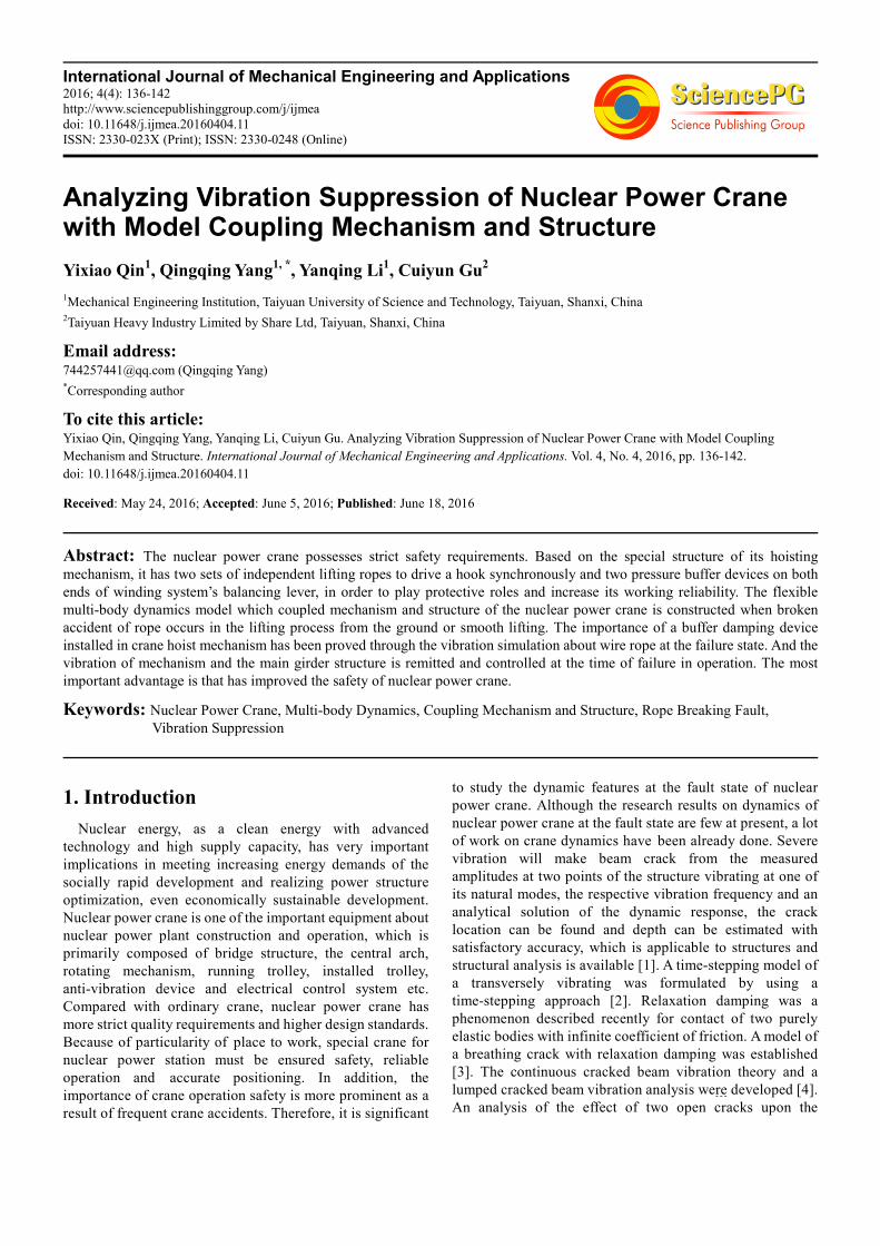
Fig. 1. Nuclear crane with circular orbit and diameter for 35 meters.
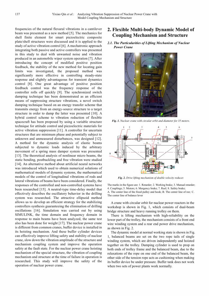
Fig. 2. Drive lifting mechanism of double velocity reducer.
The marks in the figure are: 1. Retarder; 2. Working brake; 3. Manual retarder;
4. Couplings; 5. Motors; 6. Mergency brake; 7. Reel; 8. Safety brake;
A. The center line of the fixed pulley and hook; B. The center line of ree; C.
The center line of balance lever
A crane with circular orbit for nuclear power reactors in the
workshop is shown in Fig. 1, which consists of dual-beam
bridge structure and heavy running trolley on them.
There is lifting mechanism with high-reliability on the
lower part of the trolley, the mechanism consists of a front end
wire winding system and a rear end power drive mechanism,
as shown in Fig. 2.
The dynamic model at normal working state is shown in Fig.
1, balanced beams are set on the two rope tails of single
winding system, which are driven independently and hoisted
together on the trolley. Damping cylinder is used to prop on
both ends of trolley frame and the balanced beam, due to the
relaxations of the rope on one end of the balanced beam, the
other side of the tension rope acts as cushioning when making
its buffer device be under pressure. Buffer tank does not work
when two sets of power plants work normally.
International Journal of Mechanical Engineering and Applications 2016; 4(4): 136-142 138
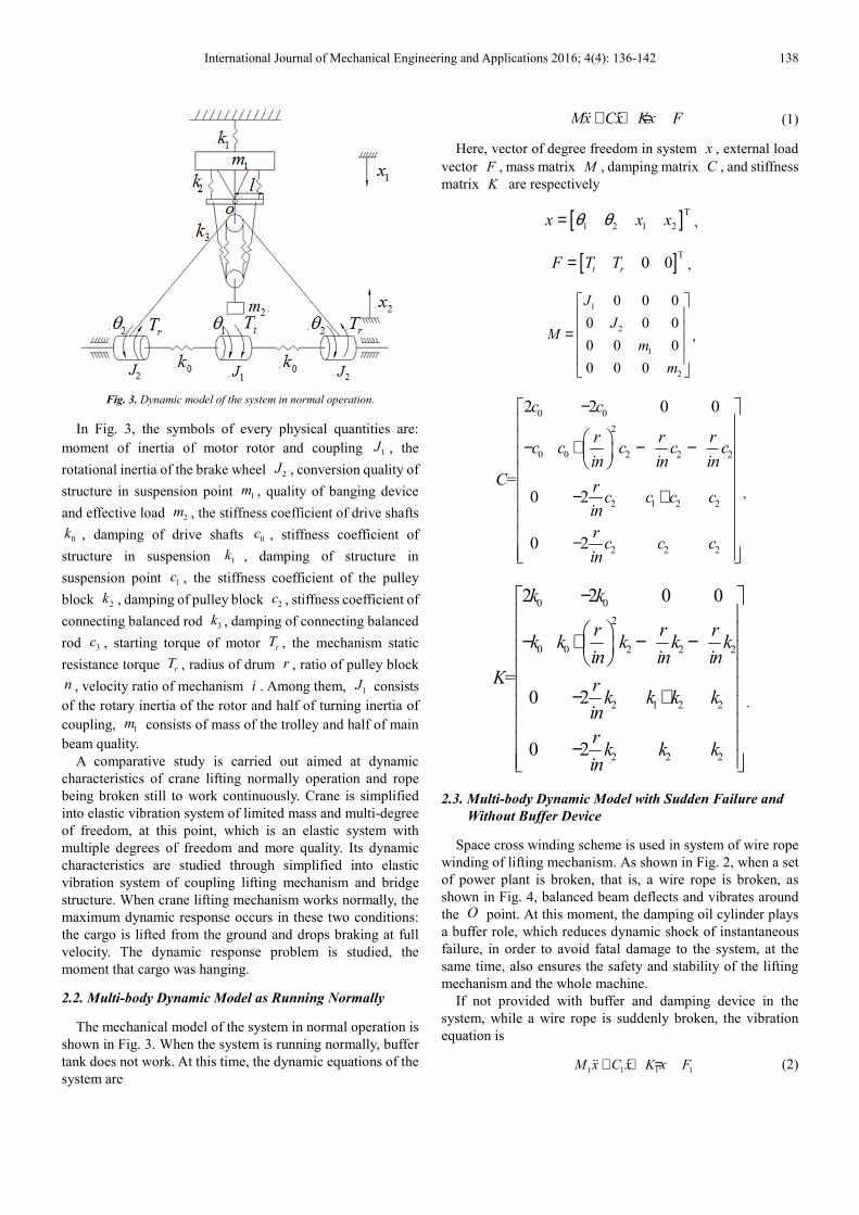
Fig. 3. Dynamic model of the system in normal operation.
In Fig. 3, the symbols of every physical quantities are:
moment of inertia of motor rotor and coupling 1J , the
rotational inertia of the brake wheel 2J , conversion quality of
structure in suspension point 1m , quality of banging device
and effective load 2m , the stiffness coefficient of drive shafts
0k , damping of drive shafts 0
c , stiffness coefficient of
structure in suspension 1k , damping of structure in
suspension point 1c , the stiffness coefficient of the pulley
block 2k , damping of pulley block 2
c , stiffness coefficient of
connecting balanced rod 3k , damping of connecting balanced
rod 3c , starting torque of motor t
T , the mechanism static
resistance torque rT , radius of drum r , ratio of pulley block
n , velocity ratio of mechanism i . Among them, 1J consists
of the rotary inertia of the rotor and half of turning inertia of
coupling, 1m consists of mass of the trolley and half of main
beam quality.
A comparative study is carried out aimed at dynamic
characteristics of crane lifting normally operation and rope
being broken still to work continuously. Crane is simplified
into elastic vibration system of limited mass and multi-degree
of freedom, at this point, which is an elastic system with
multiple degrees of freedom and more quality. Its dynamic
characteristics are studied through simplified into elastic
vibration system of coupling lifting mechanism and bridge
structure. When crane lifting mechanism works normally, the
maximum dynamic response occurs in these two conditions:
the cargo is lifted from the ground and drops braking at full
velocity. The dynamic response problem is studied, the
moment that cargo was hanging.
2.2. Multi-body Dynamic Model as Running Normally
The mechanical model of the system in normal operation is
shown in Fig. 3. When the system is running normally, buffer
tank does not work. At this time, the dynamic equations of the
system are
Mx Cx Kx F+ + =ɺɺ ɺ (1)
Here, vector of degree freedom in system x , external load
vector F , mass matrix M , damping matrix C , and stiffness
matrix K are respectively
[ ]T
1 2 1 2x x xθ θ= ,
[ ]T0 0t rF T T= ,
1
2
1
2
0 0 0
0 0 0
0 0 0
0 0 0
J
JM
m
m
=
,
0 0
2
0 0 2 2 2
2 1 2 2
2 2 2
2 2 0 0
=0 2
0 2
c c
r r rc c c c c
in in inC r
c c c cin
rc c c
in
−
− + − − − + −
,
0 0
2
0 0 2 2 2
2 1 2 2
2 2 2
2 2 0 0
=0 2
0 2
k k
r r rk k k k k
in in inK r
k k k kin
rk k k
in
−
− + − − − + −
.
2.3. Multi-body Dynamic Model with Sudden Failure and
Without Buffer Device
Space cross winding scheme is used in system of wire rope
winding of lifting mechanism. As shown in Fig. 2, when a set
of power plant is broken, that is, a wire rope is broken, as
shown in Fig. 4, balanced beam deflects and vibrates around
the O point. At this moment, the damping oil cylinder plays
a buffer role, which reduces dynamic shock of instantaneous
failure, in order to avoid fatal damage to the system, at the
same time, also ensures the safety and stability of the lifting
mechanism and the whole machine.
If not provided with buffer and damping device in the
system, while a wire rope is suddenly broken, the vibration
equation is
1 1 1 1M x C x K x F+ + =ɺɺ ɺ (2)

139 Yixiao Qin et al.: Analyzing Vibration Suppression of Nuclear Power Crane with
Model Coupling Mechanism and Structure
Where, degree of freedom vector in system x which is
unchanged, mass matrix M , external load vector F , damping
matrix 1
C , stiffness matrix 1
K
become respectively
[ ]T
12 0 0
t rF T T= ,
1
2
1
1
2
0 0 0
0 2 0 0
0 0 0
0 0 0
J
JM
m
m
=
,
0 0
2
0 0 2 2 2
1
2 1 2 2
2 2 2
0 0
=0
0
c c
r r rc c c c c
in in inC r
c c c cin
rc c c
in
−
− + − − − + −
,
0 0
2
0 0 2 2 2
1
2 1 2 2
2 2 2
0 0
0
0
k k
r r rk k k k k
in in inK r
k k k kin
rk k k
in
−
− + − − = − + −
.
2.4. Multi-body Dynamic Model with a Buffer Device When
Either of Two Wire Ropes Is Broken
By the rope winding method of crane lifting mechanism, the
load distribution on two wire ropes can be balanced, and
there are two wire ropes, if one is broken, the other can keep
load, so the balance of the spreader is maintained. Meanwhile
this winding method of wire rope also avoids hook’s
horizontal movement during the lifting process. Buffer
cylinders are installed at both ends of the balance lever device,
its function is that another rope can bear all the load in the
buffer mode after one of the two wire ropes is broken.
Choosing rationally buffer cylinder can reduce load impact
factor caused by sudden rupture of a wire rope and reducing
short-time maximum impact load next wire rope bears under
the condition of the accident. A dynamic model is established
when system is in fault. To verify that vibration caused by
lifting mechanism buffer cylinder has a certain attenuation,
and accordingly the advantages of the system and the fidelity
of the model can also be verified.
As shown in Fig. 4. and Fig. 5, there are a system failure
when one rope is suddenly broken, balancing rod deflects
around the rotating shaft O , adding one degree of freedom
Fig. 4. Dynamic model with buffer cylinder when a failure occurs in the
course of the lifting.
Fig. 5. The detailed drawing of the lifting mechanism with special structure at
fault state.
The dynamic equation of the system is
Mx Cx Kx F+ + =ɺɺ ɺ (3)
Where,
[ ]T
1 2 1 2x x xθ θ θ= ,
[ ]T2 0 0 0t rF T T= ,
2
2
2
2
0 0 0 0
0 2 0 0 0
0 0 0 0 0
0 0 0 0
0 0 0 0
J
J
M
m
m
=
,
0 0
2
2
0 0 2 2 22
2 2
3 2 2
2
2 1 2 2
2
2 2 2
0 0 0
2
3
20 ( )
3
20
3
20
3
k k
lrkr r rk k k k k
in in inin
rk kl k k kK in n
k lrk k k k
in n
k lrk k k
in n
−
− + − − + − −= − + −
,

International Journal of Mechanical Engineering and Applications 2016; 4(4): 136-142 140
0 0
2
20 0 2 2 22
22 3 2 2
22 1 2 2
22 2 2
0 0 0
2
3
20
3
20
3
20
3
c c
lrcr r rc c c c c
in in in in
crc l c c cC in n
c lrc c c c
in n
c lrc c c
in n
−
− + − −
+ − − = − + −
3. Analyzing Dynamic Characteristics
As an integrated software package, SIMULINK is used to
carry out dynamic system modeling and simulating. By using
standard module of SIMULINK module library and setting
parameters of corresponding module and its simulation
system, and simulation system of lifting mechanism can be
formed.
The method is simple and direct in modeling, calculation
process and results analysis, and can fully guarantee the
accuracy of result analysis, better solve coordination between
accuracy of system modeling and numerical solution. At the
same time, this method of the research can ascertain
conveniently the dynamic load characteristics of hoisting
mechanism of specific crane under different working
conditions. It also overcomes the existing deficiency of
methods for determining dynamic load coefficient, thus
providing the reliable basis for the design of the crane.
3.1. Simulation Parameters and Results
Fig. 6. Time response of velocity and acceleration for the main girder and heavy loads with buffer cylinder and without buffer tank.

141 Yixiao Qin et al.: Analyzing Vibration Suppression of Nuclear Power Crane with
Model Coupling Mechanism and Structure
Fig. 7. Frequency response of velocity and acceleration for the main girder and heavy loads with buffer cylinder and without buffer tank.
The simulation experiments aimed at the time domain and
frequency response of the main beam and heavy loads with
failure, when the cargo is lifted by the lifting mechanism for
15s. The system parameters has been properly processed in
virtual processing, value is taken as 6n = , 40i = , 0 5r .= ,6
1 1 04 10m . kg= × ,5
2 1 29 10m . kg= × ,7
1 8 8 10k . N / m= × ,
6
2 2 76 10k . N / m= × , 1 182110c N s / m= ⋅ , 259000c N s / m= ⋅ ,
2
1 24 5J . kg m= ⋅ , 2
2 0 7J . kg m= ⋅ , 3933t
T N / m= ,
3071r
T N / m= . Simulation results are shown in Fig. 6 and 7
and Table 1.
3.2. Comparative Analysis of Simulation Results
As seen from Fig. 6 and 7 and Table 1, compared with the
system without the buffer cylinder device, when there are
faults in the system, the amplitudes of the beam displacement,
velocity, the acceleration and gravitational acceleration with
the buffer cylinder device are reduced while the respective
standard deviation are also reduced.
Table 1. Simulation results.
a Evaluation index Displacement Velocity Acceleration
1 2 3 1 2 3 1 2 3
b
Max 8.86 5.23 41% 1.99 0.85 57.10% 1.92 1.51 21.30%
Min 1.37 1.78 30.30% -2.88 -2.21 23.30% -2.39 -1.53 35.90%
Standard deviation 2.07 2.01 2.80% 0.65 0.53 19.30% 0.55 0.46 16.50%
c
Max -1.4 -2.14 53%
Min -9.64 -9.64 0
Standard deviation 2.31 2.26 2.25%
The marks in the table are 1. Without MRFD; 2. With MRFD; 3. Reduced Percentage
a. Structure, b. Main girder, c. Heavy load.
According to the simulation results, it is obvious that the
dynamic load factor of wire ropes is decreased about 13.5%,
which reduced the maximum impact load of next rope within a
very short time under the condition of accident, and at the
same time, the dynamic load factor of the corresponding beam
is also reduced accordingly. And the most obvious is that the
time for fatigue happenning is greatly reduced, the vibration of
the mechanism and the main girder structure is better
controlled and relieved when the operation is a failure, as a
consequence of which, the safety and stability of fault
operation for nuclear power crane are improved and the
accident rate and loss are reduced.
To sum up, special winding mode of drum system and
setting buffer cylinder have an obvious effect on buffer shock
of the crane that fails to work, which improves the safety and
stability of the crane in fault operation.
4. Conclusions
In this paper, the dynamic models drawing of the normal
operation of the lifting mechanism and in the case of failure
were established, in view of the working characteristics,
principle of the crane hoisting mechanism in nuclear power
plant and the results of theoretical research. Based on the
dynamic theory of the crane, ring crane of the lifting
mechanism of ring crane in failure situation has been analyzed
in detail, so as to establish the dynamic equation of the system.
Dynamic computer simulation experiment has been conducted
with SIMULINK tool in MATLAB, when a failure happens,
dynamic response of lifting mechanism has been analyzed in
detail, the moment that cargo was hanging.
1) Through dynamic theory the dynamic characteristics in
International Journal of Mechanical Engineering and Applications 2016; 4(4): 136-142 142
this paper was studied, by simplifying crane lifting
mechanism into many degrees of freedom elastic vibration
system coupling the lifting mechanism and structure, in
accordance with the actual situation of the project.
2) The corresponding model was established and the
simulation experiment has been carried out, according to
the special structure of crane hoisting mechanism,
namely the buffer tank and wire rope winding system.
Simulation results show that the system can effectively
shorten the impact time of the load, effectually reduce
the system's fatigue time and protect system.
3) By wire rope winding system and setting cushion
cylinder of hoisting mechanism of nuclear power crane,
safety and reliability of the system's fault operation are
able to fully be guaranteed. It is widely used in various
crane lifting mechanism, as a result of the advantages of
this mechanism, it has the broad prospect for wide
applications.
Acknowledgements
This research was supported by the Natural Science
Foundation of Shanxi Province of China (Grant No.
2013011022-6), the National Science Foundation of China
(Grant No. 51275329) and the National Science and
Technology Major Project of China (Grant No. 2011 ZX
06001-015).
References
[1] P. N. Rizos, N. Aspragathos, A. D. Dimarogonas, Identification of crack location and magnitude in a cantilever beam from the vibration modes, Journal of Sound and Vibration 138 (3) (1990) 381-388.
[2] S. A. Neild, P. D. Mcfadden, M. S. Williams, A discrete model of a vibrating beam using a time-stepping approach, Journal of Sound and Vibration 239 (1) (2001) 99-121.
[3] I. Argatov, V. L. Popov, T. Rademacher, M. Zehn, A model of a breathing crack with relaxation damping, International Journal of Engineering Science 93 (2015) 46-50.
[4] T. G. Chondros, A. D. Dimarogonas, J. Yao, A continuous cracked beam vibration theory, Journal of Sound and Vibration 215 (1) (1998) 17-34.
[5] W. M. Ostachowicz, M. Krawczuk, Analysis of the effect of cracks on the natural frequencies of a cantilever beam, Journal of Sound and Vibration 150 (2) (1991) 191-201.
[6] V. Balamurugan, S. Narayanan, Shell finite element for smart piezoelectric composite plate/shell structures and its application to the study of active vibration control, Finite Elements in Analysis and Design 37 (9) (2001) 713-738.
[7] A. Zolfagharian, A. Noshadi, M. R. Khosravani, M. Z. Md. Zain, Unwanted noise and vibration control using finite element analysis and artificial intelligence, Appl Math Model 38 (9) (2014) 2435-2453.
[8] S. N. Mahmoodi, M. Ahmadian, Active vibration control with modified positive position feedback, J Dyn Syst Meas Control 131 (4) (2009) 1-8.
[9] M. I. Friswell, D. J. Inman, The relationship between positive position feedback and output feedback controllers, Smart Mater Struct 8 (3) (1999) 285.
[10] K. X. Li, J. Y. Gauthier, D. Guyomar, Structural vibration control by synchronized switch damping energy transfer, Journal of Sound and Vibration 330 (2011) 49-60.
[11] Q. Hu, G. Ma, Adaptive variable structure controller for spacecraft vibration reduction, IEEE Trans Aerosp Electron Syst 44 (3) (2008) 861-876.
[12] T. M. Seigler, J. B. Hoagg, Filtered dynamic inversion for vibration control of structures with uncertainty, J Dyn Syst Meas Control 135 (4) (2013).
[13] Y. H. Lin, M. W. Trethewey, Finite element analysis of elastic beams subjected to moving dynamic loads, Journal of Sound and Vibration 136 (2) (1990) 323-342.
[14] W. Xia, L. Wang, L. Yin, Nonlinear non-classical microscale beams: Static bending, postbuckling and free vibration, International Journal of Engineering Science 48 (2010) 2044-2053.
[15] H. Alli, A. Uar, Y. Demir, The solutions of vibration control problems using artificial neural networks, Journal of the Franklin Institute 340 (2003) 307-325.
[16] B. Saldivar, S. Mondie. Drilling vibration reduction via attractive ellipsoid method, Journal of the Franklin Institute 350 (2013) 485-502.
[17] Y. A. Huang, MATLAB 7.0/Simulink 6.0 Development of modeling and simulation of advanced engineering [M]. Beijing: Tsinghua University Press 12 (2005).