analyzing architectural styles - acme - the acme...
TRANSCRIPT

Analyzing Architectural Styles
Jung Soo Kim ∗ and David Garlan
School of Computer ScienceCarnegie Mellon University
5000 Forbes Avenue, Pittsburgh, PA 15213, USA
Abstract
The backbone of most software architectures and component integration frame-works is one or more architectural styles that provide a domain-specific designvocabulary and a set of constraints on how that vocabulary is used. Today’s archi-tectural styles are increasingly complex, involving rich vocabularies and numerousconstraints. Hence, designing a sound and appropriate style becomes an intellectu-ally challenging activity. Unfortunately, although there are numerous tools to helpin the analysis of architectures for individual systems, relatively less work has beendone on tools to help in the design of architectural styles. In this paper we addressthis gap by showing how to map an architectural style, expressed formally in anarchitectural description language, into a relational model that can then be checkedfor properties, such as whether a style is consistent, whether a style satisfies somepredicates over its architectural structure, and whether two styles are compatiblefor composition.
1 Introduction
The discipline of software architecture has matured substantially over the pastdecade: today we find growing use of standards [1,39,43], architecture-baseddevelopment methods [9,13,32], and handbooks for architectural design anddocumentation [10,12]. And, as a significant indicator of engineering maturity,we are also seeing a growing body of research on ways to formally analyzeproperties of architectures, such as component compatibility [7], performance[15], reliability [49], style conformance [44], and many others.
One of the important pillars of modern software architecture is the use ofarchitectural styles [5,10,12,45]. An architectural style defines a family of re-lated systems, typically by providing a domain-specific architectural design
∗ Corresponding author.Email address: [email protected] (Jung Soo Kim).
Preprint submitted to Elsevier 22 January 2010

vocabulary together with constraints on how the parts may fit together. Ex-amples of common styles range from the very generic, such as client-serverand pipe-filter [45,10], to the very domain-specific, such as NASA’s MissionData Systems (MDS) style [18,17] and the IEEE Distributed Simulation Stan-dard [31,2].
The use of styles as a vehicle for characterizing a family of software architec-tures is motivated by a number of benefits. Styles provide a common vocab-ulary for architects, allowing developers to more easily understand a routinearchitectural design. They form the backbone of product-line approaches, al-lowing the reuse of architectures across many products, and supporting com-ponent integration. By constraining the design space, they provide opportu-nities for specialized analysis [4]. And in many cases they can be linked to animplementation framework that provides a reusable code base, and, in somesituations, code generators for significant parts of the system (such as [22]).
Consequently an ever-increasing number of architectural styles are being de-fined. In many cases new styles are elaborations of existing styles. For example,a company might constrain Java EE-based architectures [37] to support par-ticular types of business services. In other situations new styles may be combi-nations of other styles. For example, one might combine a closed-loop controlarchitecture with a publish-subscribe style to satisfy needs for monitoring ofautomotive control software.
Defining a new style, however, is not an easy task. One must take care that thesystem building blocks fit together in the ways expected, that each instanceof the style satisfies certain key properties, and that constraints on the use ofthe style are neither too strong nor too weak. Thus defining styles becomesan intellectual challenge in its own right. Indeed, in many ways the needfor careful design of architectural styles far exceeds the needs for individualsystems, since flaws in an architectural style can impact every system that isbuilt using it.
Unfortunately, despite significant progress in formal analysis of the architec-tures for individual systems, there is relatively little to guide the style designer.Answering questions like whether a given style specifies an appropriate set ofsystems, whether it can be combined consistently with another, or whether itretains the essential properties of some parent style, is today largely a matterof trial and error. In fact, typically style designers cannot detect fundamentalerrors in a style until someone actually tries to implement a particular systemin that style, when the cost of change is very high.
To address this gap, ideally what we would like to have is a way to formallyexpress and verify properties of architectural styles. Even better would be a setof standard sanity checks that every style designer should consider. Better still,
2

we would hope that many of these checks could be carried out automatically.
In this paper we describe an approach that does exactly that with respect tostructural aspects of architectural styles. Specifically, we show how to map anarchitectural style, expressed in an architectural description language, into arelational model that can be checked tractably for various properties relevantto a style designer using existing model checkers and model generators. Ad-ditionally, significant parts of this approach can be automated, including thetranslation of a style into a relational model, invocation of a set of standardsanity checks on styles, and reverse translation of the output of the analy-sis tools (e.g., counterexamples) back into an architectural model where theresults of the analysis can be viewed in terms of architectural structures.
The main contributions of this work include (a) a translation scheme fromarchitectural style definitions into relational models, and specifically thosesupported by Alloy [26,27]; (b) an enumeration of a number of importantclasses of properties that a style designer should be concerned with, such asstyle consistency and compatibility of two styles for merging; (c) techniques toencode such properties in the relational model where they can be checked usingtools such as the Alloy Analyzer; and (d) performance measurements thatdemonstrate the tractability of the techniques and explore size and complexitylimitations.
In Section 2 we consider related work. Section 3 discusses architectural styles:what they are, how they can be characterized formally, and what kinds ofproperties we would like them to have. Section 4 provides a brief introductionto Alloy and the Alloy Analyzer, the target modeling language and analysistool that we will be using to check properties of styles. Section 5 provides anoverview of the approach and tools. Section 6 then presents the translationapproach, showing how to map formal descriptions of architectural styles intoAlloy, and highlighting places where that translation is non-trivial. Section 7examines a variety of important style analyses and shows how to map theseinto Alloy where the Alloy Analyzer can be used to check them. Section 8demonstrates how a realistic architectural style can be analyzed using the ap-proach presented in this paper and explores some of the performance issuesrelated to scaling to large-scale styles. Section 9 considers how the performanceof the analysis scales with respect to several model complexity dimensions. Sec-tion 10 discusses the strengths and limitations of the approach, and considersfuture work.
2 Related Work
There are three broad areas of related work. The first is formal representationand analysis of software architecture. Since the inception of software architec-ture over a decade ago, there have been a large number of researchers interested
3

in formal description of architectures. These efforts have largely focused on thedefinition and use of architecture description languages (ADLs) [35]. Many ofthese languages were explicitly defined to support formal analysis, often usingexisting (non-architectural) formalisms for modeling behavior. For example, anumber of ADLs have used process algebras [7,34] to specify abstract behaviorof an architecture, and to check for properties like deadlock freedom of con-nector specifications. Others have used rewriting rules [25], sequence diagrams[24], event patterns [33], and many other formal underpinnings.
This existing body of work on analysis of software architectures has primarilyfocused on the problem of analyzing the properties of individual systems.That is, given an architectural description of a particular system, the goal isto formally evaluate some set of properties of that system. Properties includethings like consistency of interfaces [42], performance [15,47], and reliability[43]. While many of these analyses assume that a system is described in aparticular style (such as one amenable to rate-monotonic analysis or queuingtheoretic modeling), unlike our work, the issue of analyzing the style itself isnot directly addressed.
There has been some research on ways to formally model architectural stylesand their properties. Early work on this carried out by Abowd et al. [5] mod-eled styles using Z [48]. In that approach one can specify general properties ofarchitectural styles, but the work lacks explicit guidance on what propertiesshould be evaluated, and it does not provide any tool-assisted support for anal-ysis. Other work has investigated formal properties of particular styles, suchas EJB [46] or publish-subscribe [16], but these have not provided any generalstyle-independent analyses. Finally, the Acme ADL was developed with thespecific intent of providing a way to formally define architectural styles, ingeneral, and to check conformance between the architecture of a system andits purported styles, in particular [20]. As we describe later, our work buildsdirectly on that formalism, extending the possibilities of analysis to the stylesthemselves.
The second area of related research is model-based design. Independently ofsoftware architecture, there has been a lot of research on using models todevelop and gain confidence in systems. Most of these have been targeted tostandard general-purpose modeling notations, such as UML [39], Z [48], orB [6], as opposed to domain-specific modeling languages, such as architecturaldescription languages. In this work we build on these general specificationlanguages using Alloy [26], one such general-purpose modeling language, asthe “assembly language” for our own analyses.
Also closely related to our research is work on model-based software engineer-ing [40]. In particular, the work by Karsai et al. [28] adopts a similar approachto meta-modeling in which new kinds of modeling languages and analyses can
4

be defined for a particular domain. This work shares the general goals of ourapproach: that it should be possible to provide customized modeling notationsand analyses to take advantage of them. However, unlike their approach, oursis focused specifically on software architectural styles and their properties.This makes our work less general, but at the same time allows us to tailor ourapproach specifically to the needs of the architectural style designer.
A third related area is that of formal languages [23]. Since an architecturalstyle defines a kind of design language, some of the problems of understand-ing a style are related to those of understanding formal languages in general.For example, determining whether a given sentence belongs to the languagegenerated by a grammar is similar to determining whether the architecture ofan individual system conforms to an architectural style. Moreover formal lan-guage results have been extended to graphs grammars, which can also be usedto represent architectural styles [36]. However, there is a significant differencebetween the kinds of properties that can be checked over such grammars andthe properties we explore in this work. Specifically, the constraint languagesfor defining architectural styles in ADLs like Acme include full first-order pred-icate logic, rendering many properties of interest undecidable [38]. As a result,in this work we take a pragmatic approach to analysis of styles, by investigat-ing the use of model checking (or more accurately, model generating) tools forcarrying out analyses.
3 Architectural Style
Software architecture is concerned with the high-level structure and proper-ties of a system [45,41]. Over time there has emerged a general consensus thatmodeling of complex architectures is best done through a set of complemen-tary views [12,1]. Among the most important types of views are those thatrepresent the run-time structures of a system. This type of view consists ofa description of the system’s components – its principle computational ele-ments and data stores – and its connectors – the pathways of interaction andcommunications between the components. In addition, an architecture of asystem typically includes a set of properties of interest, representing thingslike expected latencies on connectors, transaction rates of databases, etc.
While it is possible to model the architecture of a system using generic con-cepts of components and connectors, it is often beneficial to use a more special-ized architectural modeling vocabulary that targets a family of architecturesfor a particular domain [5,10,12,45]. We refer to these specialized modelinglanguages as architectural styles. 1
1 Styles are sometimes referred to as “architecture families,” “architectural pat-terns,” or “architectural frameworks.”
5
Architectural styles have a number of significant benefits. First, styles pro-mote design reuse, since the same architectural design is used across a set ofrelated systems. Second, styles can lead to significant code reuse. For examplemany styles (like Java EE, .Net, and most commercial service-oriented ar-chitectures) provide prepackaged middleware to support connector implemen-tations. Similarly, Unix-based systems adopting a pipe-filter style can reuseoperating system primitives to implement task scheduling, synchronization,and communication through buffered pipes. Pipe-filter styles are also seen inmodern web-based applications, such as Yahoo Pipes [3]. Third, it is easier forothers to understand a system’s organization if standard architectural struc-tures are used. For example, even without specific details, knowing that asystem’s architecture is based on a client-server style immediately conveys anintuition about the kinds of pieces in the system and how they fit together.Fourth, styles support component interoperability. Examples include CORBAcomponent-based architectures [14] and event-based tool integration [8]. Fifth,by constraining the design space, an architectural style often permits special-ized analyses. For example, it is possible to analyze certain systems built in apipe-filter style for schedulability, throughput, latency, and deadlock-freedom.Such analyses might not be meaningful for an arbitrary, ad hoc architecture– or even one constructed in a different style.
Consequently, there is a large number of architectural styles that are in usetoday – even if they are not formally named or defined as such. Indeed, therecent industrial interest in product lines and frameworks invariably resultsin the creation of new styles. This is because product lines and frameworksimplicitly define a family of systems, where architectural issues (such as whatkinds of components can be added, and how they are composed with othercomponents) are a significant part of the design. Many of these styles arespecializations or combinations of existing styles. For example, a companyspecializing in inventory management might provide a specialization of JavaEE that captures the common structures in that product domain. Other stylesmay be defined from scratch.
3.1 Formal Modeling of Architectures
Building on the large body of existing formal modeling techniques for component-and-connector architectures, we model an architecture using the following coreconcepts that appear in most modern ADLs [35], as well as UML 2.0 [39].
• Components: Components represent the principal computational elementsand data stores of a system. A component has a set of run-time interfaces,called ports, which define the points of interaction between that componentand its environment.
6

• Connectors: Connectors identify the pathways of interaction between com-ponents. Connectors may represent simple interactions, such as a single ser-vice invocation between a client and server. Or they may represent complexprotocols, such as the control of a robot on Mars by a ground control sta-tion. A connector defines a set of roles that identify the participants inthe interaction. For example, a pipe might have reader and writer roles;a publish-subscribe connector might have multiple announcer and listenerroles.• Configurations: An architectural configuration (or simply architecture or
system) is a graph that defines how a set of components are connected toeach other via connectors. The graph is defined by associating componentports with the connector roles in which they participate. For example, portsof filter components are associated with roles of the pipe connectors throughwhich they read and write streams of data.• Properties: In addition to defining high-level structure, most architectures
also associate properties with the elements 2 of an architectural model. Forexample, for an architecture whose components are associated with periodictasks, properties might define the period, priority, and CPU usage of eachcomponent. Properties of connectors might include latency, throughput, re-liability, protocol of interaction, etc.
To make such definitions precise, however, we need a formal language. In thiswork we use the Acme ADL [21], although other ADLs could have been usedinstead. Figure 1 illustrates the basic constructs in Acme for defining con-figurations. 3 The figure specifies a very simple repository architecture con-sisting of two components – a database (db) and a client (client) – con-nected by a database access connector (db access). Each component has asingle port (request and provide), and the connector through which they in-teract has two roles (user and provider). The client has a single property(avg trans per sec), its average number of transactions per second.
Implicit in most ADLs are a set of basic common structural constraints onhow ports, roles, components, and connectors may be combined. In Acmethese include the following constraints:
(1) Each port is associated with a unique component. That is, there are noorphaned ports, and no port may be part of more than one component.
(2) Dually, each role is associated with a unique connector.(3) A role may be attached to at most one port.(4) Ports may only be attached to roles, and vice versa. Hence, components
2 We use the term “elements” to refer generically to any kind of architecturalstructure: component, connector, port, or role.3 In this paper we discuss only the aspects of Acme that are necessary to explainour approach to style analysis. For a more details on the language see [21].
7

System simple_repository_system = {Component client = {Port request;Property avg_trans_per_sec: int;
}Component db = {Port provide;
}Connector db_access = {Role user;Role provider;
}Attachments = {client.request to db_access.user;db.provide to db_access.provider;
}}
Fig. 1. Simple repository system
may only interact with other components through connectors, and con-nectors may not be directly connected to other connectors. 4
Other potential topological restrictions are left unconstrained, but may be in-troduced later when defining specific styles, as noted in the next section. Theseinclude things such as the permissibility of unattached ports, unattached roles,the existence of at least one port on a component or one role on a connector,whether more than one role may be attached to a port, etc.
3.2 Formal Modeling of Architectural Styles
To define a style we add the following concepts:
• Design vocabulary: This can be specified as a set of component, connec-tor, port and role types that are available for defining a specific architecturein that style. For example, a pipe-filter style would include a pipe connec-tor type and a filter type, and a client-server style would include a clienttype and a server type, etc. Additionally, a style may define a set of prop-erty types. For example, a property type BufferSize might be defined torepresent the buffer size of a pipe.• Constraints: A style may also include constraints that describe the allow-
able configurations of elements from its design vocabulary. Some constraintsmay restrict overall topology. For example, a pipeline architecture mightconstrain the configurations to be linear sequences of pipes and filters. Or,
4 This restriction is relaxed in some ADLs, such as C2, where components may bedirectly connected to other components[35].
8

a N-tiered style might restrict clients from interacting directly with a back-end database. Other constraints may be associated with specific elements.For example, a client-server connector may be constrained to connect onlya client and a server. Constraints are therefore used to restrict the possibleconfigurations that may be created using the design vocabulary. Thus con-straints determine the set of possible systems that can be created using thebuilding blocks defined by the design vocabulary.
A style can be formally specified as a set of architectural element types to-gether with a set of constraints specified in first-order predicate logic. Typesmay be subtypes of other types, with the interpretation that a subtype satis-fies all of the structural properties of its supertype(s) and that it respects allof the constraints of those supertypes. For instance, a UnixFilter componenttype may be declared to be a subtype of Filter, adding an additional constraintthat there are exactly three ports, one each of type stdIn, stdOut, and stdErr.
A style naturally determines a collection of possible configurations: namely,those whose element types are defined by the style, and whose overall struc-ture satisfies the predicates associated with the style. We say that a systemconforms to a style if it is a member of the family of configurations determinedby that style.
Styles can be formally related to each other in various ways. One relationshipis specialization. A style can be a substyle of another by strengthening theconstraints, or by providing more-specialized versions (i.e., subtypes) of someof the element types. For instance, a pipeline style might specialize the pipe-filter style by prohibiting non-linear structures and by specializing a filterelement type to a pipeline “stage” that has a single input and output port.An N-tiered client-server style might specialize the more general client-serverby restricting interactions between non-adjacent tiers. As with element types,a substyle must respect the constraints of its superstyle, and hence defines asubset of the possible systems that the superstyle represents.
A second important relationship is conjunction. One can combine two styles bytaking the union of their design vocabularies, and conjoining their constraints.For example, one might add a database component to a pipe-filter system byconjoining a pipe-filter style with a database style. In such cases it may benecessary to also define new types of components or connectors that pertainto more than one style, such as a component type that has filter-like behavior,but that can also access a database.
Figure 2 illustrates the definition of a simple repository style in Acme. TheRepositoryStyle style includes definitions of various types of interfaces: Provideand Use port types for components, and Provider and User roles for connec-tors. The Database component type and the Access connector type provide
9

Style RepositoryStyle = {Port Type Provide = {invariant forall r:role in self.attachedRoles |
declaresType(r, Provider);}Port Type Use = {invariant forall r:role in self.attachedRoles |
declaresType(r, User);}Role Type Provider = {invariant size(self.attachedPorts) == 1;invariant forall p: port in self.attachedPorts |
declaresType(p, Provide);}Role Type User = {invariant size(self.attachedPorts) == 1;invariant forall p: port in self.attachedPorts |
declaresType(p, Use);}Component Type Database = {Port provide: Provide = new Provide;
}Connector Type Access = {Role provider: Provider = new Provider;Role user: User = new User;
}invariantexists c: component in self.components |
declaresType(c, Database);invariantexists n: connector in self.connectors |
declaresType(n, Access);}
Fig. 2. Repository style specified in Acme
the component and connector design vocabulary.
In the example the port and role types specify constraints (termed “invari-ants”) that constrain attachments between ports and roles. Specifically, con-straints on ports specify that a Provide port must be attached to a Provider
role, and that a Use port must be attached to a User role. The constraints onthe roles specify that each role must be attached to some port – that is, thereare no dangling connectors. The style also includes constraints on configura-tions dictating that at least one database and one access connector must existin any system in this style. Although not illustrated in this example, one canalso specify properties in type definitions. For example, the Provide port typemight include a property such as max-trans-per-sec, with the meaning that
10

System simple_repository_system: RepositoryStyle = {Component client = {Port request: Use = new Use;Property avg_trans_per_sec: int;
}Component db:Database = new Database;Connector db_access:Access = new Access;Attachments = {client.request as db_access.user;db.provide as db_access.provider;
}}
Fig. 3. Repository system specified using the style
every instance of this port must provide a value for this property.
As noted earlier, constraints are first-order predicates. Acme uses a notationsimilar to UML’s OCL to specify these, for example, representing universaland existential quantification with forall and exists.
To simplify specifications of constraints Acme also provides a number of built-in functions. For example, in Figure 2 attachedPorts returns the ports at-tached to the role represented by self, while declaresType(e,T) returns trueif an element e is declared to have type T. The term self refers to the entityto which the constraint is associated.
To see how this style would be used, Figure 3 shows how the system of Figure 1would be described using the style. Note how the declaration of that systemis simplified, at the same time making explicit its commonality with othersystems that use the same style.
Although the example used above is relatively simple, in practice styles maybe quite complex. They may define a rich vocabulary of elements, and the rulesfor configuration may be numerous. For example, the Mission Data Systems(MDS) defined by NASA JPL as a style for space systems [18,17,42] includesnine component types (actuators, sensors, etc.), twelve connector types, andseventy nine constraints over configurations. Figure 4 shows one such con-straints: when associated with an MDS system, it specifies that it is possibleto connect at most one controller to any of an actuator’s ports. (We will revisitthis style in Section 8.)
forall compA: ActuatorT in self.components |numberOfPorts(compA,CommandSubmitProvPortT) > 1-> (exists unique compC: ControllerTin self.components |connected(compA, compC))
Fig. 4. Example constraint of the MDS style
11

Definition of architectural styles such as MDS is a challenging intellectual ef-fort. The style designer must worry about providing an expressive and appro-priate vocabulary, as well as making sure that the style contains appropriateconstraints. If the constraints are too strong, it will rule out systems thatshould be included; if too weak, it will allow configurations that should notbe permitted.
4 Alloy
Alloy 5 is a modeling language based on first-order relational logic [26,27]. AnAlloy model represents a set of instances, and is defined using signatures andfacts. Signatures provide the vocabulary of a model by defining the types ofobjects in the model and relations between those objects. Facts are Booleanexpressions that every instance of a model must satisfy, thus restricting theinstance space of the model. Consider the following Alloy model:
module publicationsig Person {}sig Book {author: Person}sig Autobiography extends Book {}fact {all disj b1,b2:Autobiography | b1.author!=b2.author
}
Three Alloy signatures are defined: Person, Book, and Autobiography. Theauthor relation is defined over Book and Person. The Autobiography signatureis defined using signature extension as a subtype of the Book type. A globalfact in the above example prescribes that a person cannot write two autobi-ographies. It uses the Alloy keyword disj which enforces the two quantifiedobjects are distinct.
The semantics of Alloy’s subtyping is that of subsets. Additionally, any twosubtypes of a type are disjoint: they share no element. There are two built-intypes in Alloy: univ and none. univ is the supertype of all other types (andincludes all elements), and none is the subtype of all other types (and includesno element).
Models written in Alloy can be analyzed by the Alloy Analyzer, which searchesfor an instance of an Alloy model. Depending on the type of command to exe-cute, the Alloy Analyzer can be used either as a prover which finds a solutionthat satisfies a given predicate, or as a refuter which finds a counterexamplethat violates a given assertion.
5 For this research we used Alloy Version 4.
12

The Alloy Analyzer is a bounded checker, guaranteeing the correctness of theresult only within a bounded instance space. The maximum number of objectsfor each top-level type can be specified when giving the Analyzer a commandto execute.
Consider the following Alloy model, which extends the previously definedpublication model by additionally defining a command to execute:
module analysisopen publicationpred good_world[] {all p: Person | some b: Book | b.author = p
}run good_world for 5
When executed, the Alloy Analyzer searches for a solution that satisfies thepredicate good world, which claims that it is possible for every person to writeat least one book. The solution should have no more than five objects for eachtop-level type (Person and Book in this example).
We will introduce additional details of the Alloy language as necessary toexplain our use of it for modeling architectural styles. For further informationabout Alloy refer to [27].
5 Overview of Approach
As illustrated in Figure 5, our overall approach is to provide a translationscheme to map Acme style specifications into Alloy models. In addition, weprovide a way to specify (in architectural terms) analyses that we wish to carryout on that style. These are translated into Alloy analysis specifications that,in combination with the translated style and a set of baseline shared definitions(Common Model in the figure) can be performed by the Alloy Analyzer. Resultsfrom the Alloy analysis are then automatically mapped back to architecturalspecifications in Acme, where style designers can use them to improve theirstyle specifications.
In the next section we examine in detail how we map styles to Alloy. Examplesof common analyses for architectural styles and their translation to Alloy arediscussed in Section 7.
6 Representing Styles in Alloy
We now present our style translation scheme, illustrating the ideas with therepository style presented in Section 3. We begin with a high-level overviewand then consider in more detail how styles are translated.
13

Fig. 5. Overall flow of style analysis
To translate a style into a relational model such as Alloy one must handle fourthings.
1. Basic architectural types and relations: Our approach is to encodethe four basic element types (components, connectors, ports and roles) astop-level Alloy signatures. Containment and attachment relations are en-coded as binary relations between the respective types. A system can thenbe encoded as a top-level signature containing sets of components and con-nectors.
2. Style-specific architectural types: The element types defined by a spe-cific style are modeled as Alloy signatures extending the signature of theirrespective supertypes. For example, the Database type in the repositorystyle is modeled as a signature extending the Component signature. This ap-proach naturally accommodates new architectural types defined as subtypesof other style-specific types. Here we exploit the crucial point of agreementbetween an ADL (like Acme) and Alloy that subtyping is viewed as a subsetrelationship.
3. Constraints: Architectural constraints are modeled in a straightforwardway as Alloy formulae, since both are expressed in predicate logic. Com-mon constraints (in the Common Model of Figure 5) are modeled as Alloyfacts that must be satisfied. Style-specific constraints are modeled as Alloypredicates that can be selectively enabled depending on the type of analysis.
4. Functions and Expressions: As noted earlier, Acme provides a set ofbuilt-in functions (such as connected(c1,c2) that test for the existence ofa direct connection between two components) that are crucial for making iteasy to express constraints in natural architectural terms. To handle these,we use Alloy functions. Additionally one must handle the data types inconstraint expressions. Integers and sets are straightforward, because Alloysupports these directly. However, care must be taken for other expressionslike floats, strings.
14

To carry out the translation we begin by defining a common Alloy model,cnc view, that models the generic style-independent architectural types (com-ponent, connector, port, role, and system) and the implicit constraints thatevery architectural model must obey (as enumerated in Section 3.1). Next wetranslate an individual style into an Alloy model that imports the commonmodel so that generic style constraints are enforced in the translated model. Ifa style is derived from other styles, those superstyles must also be translatedinto their own models, and imported into the translated substyle.
Mechanically, the translation of a style is a multi-step process. First the targetstyle is parsed. The parsed style is then preprocessed to mitigate some of themodeling incompatibilities between Acme and Alloy and to reduce the sizeof the translated model. For example, as explained later, certain Acme datatypes that are missing in Alloy are converted into integers. The translationscheme is then applied to the preprocessed Acme style. Once translated, theresulting Alloy model is optimized to make analysis run faster.
In the remainder of this section we first show how generic element types andimplicit constraints are translated into Alloy. Then we show how a style istranslated. 6 Along the way, we consider some of the areas where style trans-lation is problematic, or where there are alternative approaches for translationthat might have been chosen.
6.1 An Alloy Model for Shared Architectural Concepts
We model the basic element types as top-level Alloy signatures. The architec-tural relations, specifically containment and attachment relations, are modeledas Alloy relations. Additionally, Alloy facts are added to enforce implicit ar-chitectural constraints. Consider the following Alloy model:
module cnc_viewsig Component {ports: set Port, system: System}sig Connector {roles: set Role, system: System}sig Port {comp: Component}sig Role {conn: Connector, attachment: lone Port}
one sig self extends System {}abstract sig System {components: set Component,
connectors: set Connector}
fact {~ports = comp && ~roles = conn}fact {~components = Component<:system}
6 In this paper we define the translation rules informally. Formal translation rulescan be found in [30].
15

fact {~connectors = Connector<:system}
There are four top-level signatures to model the basic element types and aSystem signature to model a system. Note that System signature is defined asabstract, meaning that the signature cannot have an object without explicitlyextending it. In the model above the self signature extends the System sig-nature, and it is defined with the Alloy keyword one, thereby restricting thesignature to be a unique. This naming scheme allows us to use the term self
when we want to refer to the system being analyzed.
Containment relations (e.g., between ports and components) are defined asAlloy relations. First, ports and roles relations identify the set of ports or rolesa component or connector has, respectively. comp and conn relations identifythe parent component or connector that a port or role belongs to. Likewise,components, connectors, and system relations model the containment relationbetween components or connectors and systems.
The attachment relation between ports and roles is defined as the attachment
relation, which identifies a port to which a role may be attached. Since, ingeneral, a role need not be attached to a port, it is modeled as an optionalrelation using the Alloy keyword lone, which indicates zero or one.
By themselves, the signatures of cnc view model above provide the basic vo-cabulary of generic architectural structure. They naturally encode the factthat ports are part of components. (For example, we may access the ports ofa component c with the expression c.ports.) The same applies to connectorsand roles.
However, we also need to make sure that any declared port or role is associatedwith the right component or connector, respectively. To do this we add anadditional fact in the model, which states that comp is the inverse relation ofport and that conn is the inverse relation of roles by using the Alloy inverserelation operator ~. This fact guarantees that if a port appears in the set ofports owned by a component, that component will also be the parent of theport. The same applies to a role and a connector. Similarly, it is guaranteedthat if a component or connector belongs to a system, the system will alsobe the parent of the component or connector. The Alloy operator <: denotesdomain restriction, which is used here to disambiguate two system relations.
This encoding is certainly not the only way of modeling the basic architecturalconcepts in Alloy. In an earlier version of our translation scheme, for exam-ple, we included a shared supertype of all architectural element types, calledElement [29]. However, we found that removing the shared supertype gavemore control over the search space when executing the Alloy Analyzer, result-ing in larger scope of analysis in the same execution time. In our current ap-proach Element is translated into the union Component+Connector+Port+Role
16

for the same purpose.
Another alternative would be to remove redundant relations. In the modelabove, for example, ports and comp depend on each other. Therefore, formallyspeaking, one is redundant and could be removed by replacing its occurrencewith the inverse relation of the other. If comp is removed, however, one wouldhave to add additional facts to ensure that ports and roles have unique owners.Without those facts the inverse of ports may not be a function, i.e., a portmay belong to more than one component or to no component at all. The samereasoning for redundant relations applies to other containment relations.
6.1.1 Built-in functions
As illustrated earlier, Acme provides a collection of built-in functions that areused for various purposes in constraint expressions: to check type conformanceor structural connectivity, to access the parent of an element, or to manipulatesets. For example attached(r,p) returns true if role r is attached to port p.
Alloy allows one to define functions, thereby providing a natural way to encodesuch built-in functions. An exception is that for the built-in functions returninga Boolean value we use Alloy predicates rather than functions that return aBoolean. Since Alloy has no built-in support for Booleans, one would otherwisehave to create these as user-defined signatures. Hence the use of predicatesmakes analysis more efficient, not requiring extra signatures and the need toencode (and decode) Boolean values.
The following are the Alloy translations of the built-in functions used in theexamples of this paper. 7 These predicates augment the cnc view model pre-sented above.
pred declaresType [element: univ, type: set univ] {element in type
}pred attached [r: Role, p: Port] {
r -> p in attachment}pred attached [n: Connector, c: Component] {
n -> c in roles.attachment.component}pred connected [c1: Component, c2: Component] {
some c1.ports.~attachment.connector & c2.ports.~attachment.connector}
The Alloy operator -> represents a binary relation between scalars. The opera-tor in tests the subset relation. The dot operator is relational join. In the pred-
7 For the full translations of built-in functions see Appendix A.
17

icates above, the roles relation is from Connector to Role, the attachment rela-tion is from Role to Port, and the component relation is from Port to Component.Therefore, the roles.attachment.component relation is from Connector toComponent.
As illustrated above, some built-in functions are overloaded. Here attached
can be applied to a role and a port, returning true if they are attached. It canalso be applied to a component and a connector, returning true if a role ofthe connector is attached to a port of the component. Because these functionshave different parameter types, Alloy can resolve these overloaded functionnames automatically.
6.2 Translating a Style
We now look at how we translate an Acme style into an Alloy model usingthe repository style introduced in Figure 2 as a running example.
The translation of a style consists of the translation of its types and its con-straints. Note that the common model cnc view, which contains basic def-initions for built-in features of Acme language, is imported using the open
command. The overall structure of a translated Alloy model will look likethis:
module RepositoryStyleopen cnc_view// translations of type definitions...// translations of constraints...
6.2.1 Translating type definitions
After translation each new port and role type becomes an Alloy signatureextending the top-level signature, Port or Role respectively, either as an im-mediate subtype or a subtype of another port or role signature. The sameis true for each component and connector type with respect to the top-levelsignature Component or Connector, respectively.
To illustrate, the translation of the port, role, component and connector typesof the repository style is as follows:
sig Use extends Port {}sig Provide extends Port {}sig User extends Role {}sig Provider extends Role {}
18

sig Database extends Component {provide:Provide}sig Access extends Connector {provider:Provider, user:User}
When a subtype is defined in Alloy, all the fields defined in its supertypes areautomatically made available in the subtype definition. For example, supposethere is a role user of User type. Then an expression like user.attachment isvalid since attachment is defined in the supertype Role.
The same principle holds for style-specific types that are defined as subtypes ofother style-specific types: fields of the supertype are available to the subtype.Thus we exploit the natural congruence between “subtyping as subsetting”that exists in both Acme and Alloy.
One important issue for this translation step is that the uniqueness of portsand roles is not guaranteed with the translation above. Suppose there are twoinstances a1 and a2 of the Access connector type. With the model above it ispossible that a1.user and a2.user could refer to the same role. Furthermore,it is also not enforced that the type-specific ports and roles are included in theports and roles relations defined in the Component and Connector signatures,respectively. Hence, to enforce the rules of valid structure extra constraintsare needed. Consider the additional Alloy fact added to the translation above:
fact {(Database<:provide) in ports(Access<:provider + Access<:user) in roles
}
The Alloy binary operator <:, denoting domain restriction, is used to disam-biguate overloaded relations by giving a specific domain, which in this caseis either a component type or a connector type. The keyword in denotes setinclusion. Thus by using two such facts we can guarantee that all the type-specific ports and roles are included in the ports and roles relations. As aresult, a1.roles always gives all the roles that belong to just the connector a1
regardless of its type. The same is true for components.
From this it can be inferred that all such type-specific ports and roles areunique. Recall that the inverse of the ports and roles relations, which arecomp and conn relations respectively, are functions. Thus, there cannot be aport or a role that belongs to more than one component or one connector.
Every port or role of components or connectors in a style is similarly includedin Alloy facts as above. The translation function automatically generates thefacts by scanning the type definitions of a style.
19

6.2.2 Translating property types and expressions
Like other ADLs, Acme supports various property types. Primitive propertytypes in Acme are integer, string, float, enumeration, and boolean. Compoundtype constructors supported in Acme are set, sequence, and record. Alloy, onthe other hand, currently supports only integer, boolean, and object expres-sions. Thus, the translator must map the property types and expressions ofAcme into the supported types in Alloy.
During preprocessing, string, enumeration, and float types are converted intointeger types, while their values are encoded as integer values. Thus after pre-processing there remain only two primitive property types and expressions totranslate: integer and boolean. During the translation both types are trans-lated into integer object types in Alloy.
To translate Acme’s three compound property type constructors (set, se-quence, record) is straightforward: set and sequence types are directly trans-lated into the corresponding types in Alloy; record types are translated into anew signature with each field recursively translated as necessary.
6.2.3 Translating constraints
Translation of Acme constraints is straightforward because constraints aremodeled as boolean expressions in both Acme and Alloy. When carrying outthe translation we translate “local” constraints separately – those that are at-tached to individual types – from “global” constraints – those that are includedat the system level. Each of these is included in its own named predicate. Thisis done to support analyses that need to refer to these separately, such asshowing that some global constraint is implied by the local constraints.
To illustrate, the following Alloy constraints represent the translation of thelocal and global constraints in the repository style:
pred RepositoryStyle_constraints_local[] {all self: Provide |
(all r: self.~attachment | declaresType[r, Provider])all self: Use |
(all r: self.~attachment | declaresType[r, User])all self: Provider |
(#(self.attachment) = 1) &&(all p: self.attachment | declaresType[p, Provide])
all self: User |(#(self.attachment) = 1) &&(all p: self.attachment | declaresType[p, Use])
}pred RepositoryStyle_constraints_global[] {some c: self.components | declaresType[c, Database]
20

some n: self.connectors | declaresType[n, Access]}pred RepositoryStyle_constraints[] {RepositoryStyle_constraints_local()RepositoryStyle_constraints_global()
}
The translation of each local constraint always begins with a universal quan-tification using self as the name of bound variable. Use of the variable self
simplifies the translation functions because it is a built-in object name inAcme, representing the element that the local constraints are applied to. Us-ing this approach, constraints can be translated in a uniform way regardlessof whether they are local or global.
6.3 Optimization
A key issue when using any tool that relies on exhaustive state exploration istractability. If representations are not chosen carefully, the size of model thatcan be explored in a reasonable amount of time may be seriously limited.
While we defer the discussion of overall performance analysis until later, wenote that an important step in our translation scheme is optimization. Onenotable optimization that we apply is to exploit Alloy’s built-in capability toperform relational joins. We can use this capability to eliminate certain formsof quantifier nesting. 8
Specifically, a common form of constraint in a style definition is to specifyrestrictions on ports or roles. For instance one might restrict the types ofports that can be placed on a given type of component. Because a port or rolecan only be accessed through its parent, such constraints result in two levelsof quantification, as illustrated below.
invariant forall c:T in self.components |forall p in c.ports | predicate(p)
This constraint asserts that predicate(p) must hold for every port of everycomponent of T type. (Here self refers to the system as a whole, so thatself.components is the set of components in that system.) Note that twolevels of quantification are needed, and the quantified variable c is not usedin the body of the predicate. Without optimization the corresponding Alloypredicate will look like this:
all c in (self.components & T) | all p in c.ports | predicate[p]
8 As we will see later, quantifier nesting causes an exponential increase in analysistime.
21

During optimization, however, the outer quantification is removed, and theoccurrences of its bound variables are replaced with the expression for itsrange. Thus, after optimization the predicate above is simplified to this:
all p in (self.components & T).ports | predicate[p]
Specific examples of this kind of optimization are illustrated in Section 7.5.
7 Analyzing Styles
We now show how translated architectural styles can be analyzed using theAlloy Analyzer. Our approach is to provide style designers with an analysisgenerator that can generate various forms of Alloy specifications for analysis.Supported analyses include checking of:
• consistency of a style• constructability of specific architectural configuration• properties of a style• equivalence of global and local constraints• style compatibility• consistency of hybrid types
To carry out an analysis over a style the analysis generator takes one or morestyles as input, together with a specification of predicate to check against in-stances of that style. The analysis generator can also take as input a predicate,and then checks that the predicate implies the satisfaction of the constraintsof the styles. The output of the analysis generator in this case is an Alloymodel that imports the translated styles and includes a command to test thepredicate.
The Alloy Analyzer will take the generated Alloy model and execute the in-cluded command over the instances of the translated style, each of whichcorresponds to a constructible system using the style. There are conceptuallytwo types of command: one is to find an instance that passes the test, and theother is to find a counterexample that fails the test. These correspond to dif-ferent kinds of Alloy analysis models, as detailed later. In both cases, instancesare back-translated to systems of the original style for further investigation.
As noted in Section 4 the Alloy Analyzer is a bounded checker and thereforerequires the user to set scope of analysis in the form of the maximum numberof objects for each top-level signature. Under our translation scheme there arefive top-level signatures: component, connector, port, role, and system. Thesystem signature is constrained to be a singleton, reflecting the fact that weare interested in analyzing individual systems. A style designer can specify thebounds of the other top-level elements when generating an analysis model. If
22

left unspecified, the analysis generator uses a default bound of 10 components,10 connectors, 20 ports, and 20 roles. 9
Let us now see how this works for specific kinds of analyses that are relevantto style designers.
7.1 Checking the Consistency of a Style
A style is consistent if there exists at least one architectural configuration thatconforms to the style (i.e., that satisfies the style’s architectural constraints).Consistency checking is the most basic analysis to make sure that there areno internal contradictions within a style.
Style consistency can be checked simply by using the Alloy Analyzer to findan instance of the translated model of the style: if an instance is found, thestyle is consistent. If no instance can be found, the style cannot be satisfiedby any model up to the specified bound on model size.
Consider the previous example of the repository style shown in Figure 2. Sup-pose the first two universal quantifications of the constraints had been mis-takenly written, erroneously interchanging User and Provider:
Style RepositoryStyle = {Port Type Provide = {invariant
forall r in self.attachedRoles | declaresType(r, User);}Port Type Use = {invariant
forall r in self.attachedRoles | declaresType(r, Provider);}...
}
The input to the analysis generator is simply:
Check RepositoryStyle
The output of the analysis generator is the Alloy description:
module analysisopen cnc_viewopen RepositoryStylerun RepositoryStyle_constraints for 10 but 20 Port, 20 Role
9 It is usually the case that the number of ports and roles required to construct asystem is more than the number of components and connectors.
23

Since no specific bounds were indicated the scope is taken to be the default:up to 10 components and 10 connectors, and up to 20 ports and 20 roles.When executed, the Alloy Analyzer reports that no instance can be foundwithin the specified scope. At this point a style designer must decide whetherto investigate the style for conflicting constraints or to expand the scope ofsearch.
7.2 Checking the Constructability of Specific Architectural Configurations
While consistency checking formally establishes the existence of some systemsin the style, in most cases this is not as strong a check as we might like. Inparticular, we may want to explore whether there exist systems that includecertain kinds of structure. Such structures may represent configurations thatwe would expect to be consistent with the style specification. Or, they mightbe configurations that we would expect not to be representable in the style.
To check if a specific architectural configuration is constructible using a style,it is necessary to translate the architectural configuration of interest into Alloyfacts that require this configuration be present in the instances of the trans-lated style. If the Alloy Analyzer can find an instance of the translated style,supplemented with the additional facts, the specific architectural configurationis constructible.
As an example, suppose that the repository style designer wants to makesure that it is possible for two components to access a database at the sametime. To check this, we specify as input to the analysis generator the followingcommand. (Note the use of Acme syntax to specify the structure.)
Check RepositoryStyle Using
component c1 = {port use:Use = new Use;}component c2 = {port use:Use = new Use;}connector a1:Access = new Access;connector a2:Access = new Access;component d:Database = new Database;
attachment a1.user to c1.use;attachment a2.user to c2.use;attachment a1.provider to d.provide;attachment a2.provider to d.provide;
The analysis generator will create an Alloy model that augments the translatedstyle with Alloy facts that require any instance of the translated model to havetwo components connected to the same database. Specifically, the followingAlloy model will be produced:
24

module analysisopen cnc_viewopen RepositoryStyle
one sig c1 extends Component { use: Use }one sig c2 extends Component { use: Use }one sig a1 extends Access {}one sig a2 extends Access {}one sig d extends Database {}
fact { c1<:use + c2<:use in ports }fact { a1.user.attachment = c1.use
a2.user.attachment = c2.usea1.provider.attachment = d.providea2.provider.attachment = d.provide
}run RepositoryStyle_constraints for 10 but 20 Port, 20 Role
When executed, the Alloy Analyzer returns an instance that satisfies the ad-ditional facts, confirming that it is possible to have two components connectedto the same database.
In a similar way one can check that some undesirable configuration cannotexist. For instance, to check that no architecture in this style can have twodatabases the style designer would request the system to produce an instanceof a system in this style that does have that property. Any system producedby Alloy will represent a counterexample.
7.3 Checking Properties of a Style
While constructability checking demonstrates the existence of a system (ina given style) that includes specific structures, it requires style designers toexplicitly describe those structures. As a more general alternative, style de-signers can check if certain properties of a style hold for all of its constructiblesystems.
A property of a style can be checked by invoking the Alloy Analyzer with anassertion that all instances of the translated style must satisfy the property.The Alloy Analyzer then attempts to find a counterexample – i.e., an instancethat does not satisfy the property. If one is found it indicates that the propertyis not guaranteed by the style.
Consider the property of the repository style that every system of the stylemust have at least one component with a Use port. The input to the analysisgenerator is as follows. (Note the use of an Acme predicate to specify the
25

property.)
Check RepositoryStyle Satisfiesexists c in self.components |exists p in c.ports | declaresType(p, Use)
The output of the analysis generator is the following analysis model, whichasserts that all instances of the repository style within the scope of analysishave at least one component that has a Use port. 10
module analysisopen cnc_viewopen RepositoryStylecheck { RepositoryStyle_constraints[] =>some p: self.components.ports | declaresType[p, Use]
} for 10 but 20 Port, 20 Role
When executed the Alloy Analyzer reports that there is no counterexamplethat violates the assertion within the specified scope. As an aside, note thatwe would expect this result to be the case, since the Acme constraints requirethat there be a connector of Access type that has a role of User type, and thatit must be attached to a port of Use type. Thus, there must be a componentthat has a Use port.
7.4 Checking Global and Local Constraint Equivalence
There are often several ways in which one can incorporate constraints intoa style. One is to do it at a global level. For example, Figure 4 illustrateda global constraint (or universally quantified predicate) for the MDS stylethat expresses a property about all attachments to ports of actuators. Analternative is to include local constraints associated directly with the portsand roles to achieve an equivalent effect.
In general, global constraints are easier to understand and specify. However,local constraints are more efficient to evaluate incrementally by tools, andmay provide better error reporting when they are violated. As a consequence,it is sometimes useful to specify constraints locally, and then check that theycollectively imply some global constraint. For this reason we may be interestedin checking the equivalence of global and local constraints.
Consider the example of the repository style, where each port and role typehas local constraints restricting the way they can be attached – specificallythat Use roles can only be attached to User ports, and that Provide roles can
10 The nested existential quantifications have been simplified using the optimizationtechnique explained in Section 6.3.
26

only be attached to Provider ports. Suppose the style designer is consideringan alternative using global constraints to specify the same thing. The styledesigner can check the equivalence between these two forms as follows:
Check RepositoryStyle Locally Iffforall c in self.components | forall p in c.ports |forall n in self.connectors | forall r in n.roles |attached(r,p) =>(declaresType(p, Use) <=> declaresType(r, User)) &&(declaresType(p, Provide) <=> declaresType(r, Provider))
As the result the following Alloy specification will be generated. The localconstraints of the repository style should imply the alternative global version,and vice versa. Note that the original global constraints of the style are alsoincluded in the assertion.
module analysisopen cnc_viewopen RepositoryStylecheck {RepositoryStyle_constraints_global[]RepositoryStyle_constraints_local[] <=>{ all p: self.components.ports |all r: self.connectors.roles |
attached[r,p] =>(declaresType[p, Use] <=> declaresType[r, User]) &&(declaresType[p, Provide] <=> declaresType[r, Provider])
}} for 10 but 20 Port, 20 Role
When executed, the Alloy Analyzer reports that there is a counterexamplethat violates the assertion. This means that the local constraints of the repos-itory style and the alternative in global format are, in fact, not equivalent. In-spection of the counterexample reveals that the alternative global constraintspermit a system to have unattached roles of User or Provider type, while thisis prohibited by the original local constraints.
7.5 Checking Style Compatibility
It is often the case that real world systems combine multiple styles. Unfortu-nately, not all styles can be used together because they might not be compat-ible. Two styles are compatible if any system satisfying the constraints of onestyle also satisfies the constraints of the other. Note that this definition stillallows each style to have its own types and constraints over them. But whereconstraints refer to types in both styles, they must be consistent. In otherwords, when styles are compatible, any system of an individual style should
27

still be constructible using the merged set of styles.
Consider the case of merging the previously defined repository style and anew pipe-filter style shown below (after translation and simplification). Wewill test if these two styles are compatible.
module PipeAndFilteropen cnc_view
sig Input extends Port {}sig Output extends Port {}sig Source extends Role {}sig Sink extends Role {}
sig DataSource extends Component {output: Output}sig DataSink extends Component {input: Input}sig Filter extends Component {input: Input, output: Output}sig Pipe extends Connector {source: Source, sink: Sink}
fact {(Filter<:input + Filter<:output +DataSource<:output + DataSink<:input) in ports(Pipe<:source + Pipe<:sink) in roles
}pred PipeAndFilter_constraints[] {all r:Input .~attachment | declaresType[r, Sink]all r:Output.~attachment | declaresType[r, Source]all r:Source | one p:Output | attached[r, p]all r:Sink | one p:Input | attached[r, p]some Filtersome Pipeall p:Filter.ports | declaresType[p, Input] || declaresType[p, Output]all r:Pipe.roles | declaresType[r, Source]|| declaresType[r, Sink]
}
The last two predicates constrain the allowed port or role types in a filter or apipe. In the original Acme specification they were expressed using two levelsof quantification (i.e., forall f:Filter in self.components | forall p in
self.ports |...). After translation and optimization this is reduced into onelevel of Alloy quantification (cf., Section 6.3).
The following command is provided as input to the analysis generator.
Check RepositoryStyle,PipeAndFilter Compatibility
The following Alloy model will be generated, asserting bi-implication betweenthe constraints of the repository style and the constraints of the pipe-filterstyle.
28
module analysisopen cnc_viewopen RepositoryStyleopen PipeAndFiltercheck {RepositoryStyle_constraints[] <=> PipeAndFilter_constraints[]
} for 10 but 20 Port, 20 Role
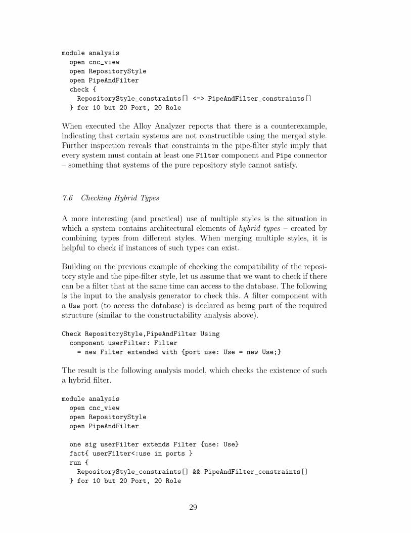
When executed the Alloy Analyzer reports that there is a counterexample,indicating that certain systems are not constructible using the merged style.Further inspection reveals that constraints in the pipe-filter style imply thatevery system must contain at least one Filter component and Pipe connector– something that systems of the pure repository style cannot satisfy.
7.6 Checking Hybrid Types
A more interesting (and practical) use of multiple styles is the situation inwhich a system contains architectural elements of hybrid types – created bycombining types from different styles. When merging multiple styles, it ishelpful to check if instances of such types can exist.
Building on the previous example of checking the compatibility of the reposi-tory style and the pipe-filter style, let us assume that we want to check if therecan be a filter that at the same time can access to the database. The followingis the input to the analysis generator to check this. A filter component witha Use port (to access the database) is declared as being part of the requiredstructure (similar to the constructability analysis above).
Check RepositoryStyle,PipeAndFilter Usingcomponent userFilter: Filter= new Filter extended with {port use: Use = new Use;}
The result is the following analysis model, which checks the existence of sucha hybrid filter.
module analysisopen cnc_viewopen RepositoryStyleopen PipeAndFilter
one sig userFilter extends Filter {use: Use}fact{ userFilter<:use in ports }run {RepositoryStyle_constraints[] && PipeAndFilter_constraints[]
} for 10 but 20 Port, 20 Role
29
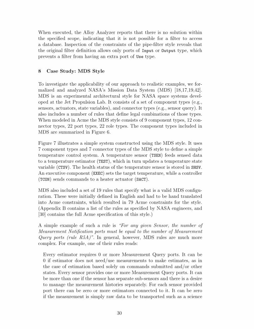
When executed, the Alloy Analyzer reports that there is no solution withinthe specified scope, indicating that it is not possible for a filter to accessa database. Inspection of the constraints of the pipe-filter style reveals thatthe original filter definition allows only ports of Input or Output type, whichprevents a filter from having an extra port of Use type.
8 Case Study: MDS Style
To investigate the applicability of our approach to realistic examples, we for-malized and analyzed NASA’s Mission Data System (MDS) [18,17,19,42].MDS is an experimental architectural style for NASA space systems devel-oped at the Jet Propulsion Lab. It consists of a set of component types (e.g.,sensors, actuators, state variables), and connector types (e.g., sensor query). Italso includes a number of rules that define legal combinations of those types.When modeled in Acme the MDS style consists of 9 component types, 12 con-nector types, 22 port types, 22 role types. The component types included inMDS are summarized in Figure 6.
Figure 7 illustrates a simple system constructed using the MDS style. It uses7 component types and 7 connector types of the MDS style to define a simpletemperature control system. A temperature sensor (TSEN) feeds sensed datato a temperature estimator (TEST), which in turn updates a temperature statevariable (CTSV). The health status of the temperature sensor is stored in SHSV.An executive component (EXEC) sets the target temperature, while a controller(TCON) sends commands to a heater actuator (SACT).
MDS also included a set of 19 rules that specify what is a valid MDS configu-ration. These were initially defined in English and had to be hand translatedinto Acme constraints, which resulted in 79 Acme constraints for the style.(Appendix B contains a list of the rules as specified by NASA engineers, and[30] contains the full Acme specification of this style.)
A simple example of such a rule is “For any given Sensor, the number ofMeasurement Notification ports must be equal to the number of MeasurementQuery ports (rule R5A)”. In general, however, MDS rules are much morecomplex. For example, one of their rules reads:
Every estimator requires 0 or more Measurement Query ports. It can be0 if estimator does not need/use measurements to make estimates, as inthe case of estimation based solely on commands submitted and/or otherstates. Every sensor provides one or more Measurement Query ports. It canbe more than one if the sensor has separate sub-sensors and there is a desireto manage the measurement histories separately. For each sensor providedport there can be zero or more estimators connected to it. It can be zeroif the measurement is simply raw data to be transported such as a science
30

SchedulerT A scheduler component is used to coordinate real-timescheduling of taskswith and MDS architecture.
ExecutableT A component type that is combined with other componenttypes to designate a component as one that is associated witha separate thread
ExecutiveT A component that sets high-level objectives of and MDS sys-tem.
ControllerT A controller is responsible for delegating the goals to otherstates, or for issuing commands to adaptors to achieve thestate, if there are goals associated with a state variable.
ActuatorT An actuator represents the interface between a controller andthe hardware. Commands are issued to actuators to get thespacecraft to do something.
EstimatorT An estimator is responsible for examining all of the availablecues (other states, sensors, or goals) and updating state vari-ables periodically to provide a current best estimate of thestates value based on available evidence (command history,other states, sensor values, etc.).
SensorT A sensor represents an interface to hardware sensor, for useby estimators.
StateVarT A state variable contains the record of the state over time,and goals associated with the state.
HealthStateVarT A health state variable stores a discrete set of data. For ex-ample, they may be used to store the history of commandssent to an actuator by a controller.
Fig. 6. Summary of component types in MDS Style
image. It can be more than one if the measurements are informative in theestimation of more than one state variable.
Formulating such constraints by hand may introduce mistakes and/or un-wanted side-effects. Therefore, automated analysis can potentially providesignificant benefits in dealing with the complexity of the style and gaininginsight into it.
Our first check was to establish that MDS was consistent for a reasonablebound on the model size. (Section 9 contains details.) Although formal con-sistency of the MDS style was easily demonstrated, a more interesting kind ofcheck was to investigate the existence of candidate architectures that containcertain minimal structures: for example, at least one controller, actuator, es-timator, sensor, and state variable. As illustrated earlier, we can do this usingthe analysis generator by providing the following input.
31

Fig. 7. An example MDS system
Fig. 8. An MDS system constructed by the Alloy Analyzer and translated into Acme
Check MDSFam Usingcomponent controller: ControllerT = new ControllerT;component actuator : ActuatorT = new ActuatorT;component estimator : EstimatorT = new EstimatorT;component sensor : SensorT = new SensorT;component statevar : StateVarT = new StateVarT;
32

The Alloy Analyzer found the instance shown in Figure 8, confirming thatsuch a structure is constructible. One interesting consequence of this processwas that while the analysis confirmed the existence of the requested struc-ture within the style, it yielded a counterintuitive example. Specifically, thegenerated model uses a single connector to connect a controller, actuator andestimator. This was hardly the intention of the original MDS style, and indi-cates that despite the large number of rules in MDS, the given formalization isunder-constrained. This caused us to go back and refine the style specification,adding new rules to eliminate structures that should not be included.
9 Performance
Whenever one uses automated tools for analysis, a critical question is how wellthose tools scale to the task at hand. This is particularly critical for exhaustivestate exploration-based tools such as model checkers, whose execution timemay vary dramatically depending on the encodings of models and the natureof the properties to be checked.
In this section we examine the way in which architecture style analysis scalesrelative to three specific factors. First is the number of architectural elementtypes in the style. Second is the number and complexity of architectural con-straints in the style, where complexity is primarily determined by quantifiernesting depth. Third is the maximum model size (or bound) in terms of num-bers of components and connectors.
Before we begin, we first note that there are conceptually two types of analysisin Alloy. One is existential analysis, which attempts to find an instance of amodel that satisfies a given predicate. For example, this kind of analysis isused to perform a style-consistency check, since consistency is guaranteed bythe existence of a single system satisfying the style. The other is universalanalysis, which checks all instances (within the bound set for the analysis)against a predicate that every instance must satisfy.
In either case, the analyzer may have to search the entire state space: for anexistential analysis, if no model exists; and for a universal analysis, if everymodel satisfies the predicate. In conducting our experiments, we carried outboth existential and universal analyses on valid styles. In the former casetypically a single system is required to be constructed, constituting a best-caseanalysis. In the later case, the analysis is required to examine every systeminstance in the search space, and hence provides a worst-case analysis.
Analysis consists of four phases. First, the architectural style is translated intoan Alloy model. Second, the Alloy Analyzer translates an Alloy model intoConjunctive Normal Form (CNF). Next, it passes the translated CNF to oneof several off-the-shelf SAT solvers to do the actual analysis. Finally, the result
33

of the SAT solver is translated back to Alloy and presented to the user. Sincethe translations involved in the first and last steps take negligible time, ourexperiments focus on how the phases two and three affect performance.
9.1 Experimental Setup
To evaluate performance we use the following experimental architectural styletemplate, which can be instantiated with a variable number of componenttypes and constraints. Each component type has two ports. Associated witheach component type is an optional local constraint (i.e., a component type-specific constraint) stating that each port should be attached to at least onerole. Additionally a global constraint (i.e., a system-wide constraint) is speci-fied; it states that every connector should have exactly two roles.
Style Experiment = {Component type CT;Component type CT1 extends CT with { port p1; port p2;invariant forall p:self.ports | size(p.attachedroles)>0; }
Component type CT2 extends CT with { port p1; port p2;invariant forall p:self.ports | size(p.attachedroles)>0; }
...Component type CTn extends CT with { port p1; port p2;invariant forall p:self.ports | size(p.attachedroles)>0; }
invariant forall n in self.connectors | size(n.roles) == 2;}
In all of the experiments we use an equal number of components and connec-tors for the model bound. The number of ports and roles is set to be doublethe number of components and connectors, for reasons indicated earlier. Weuse MiniSat as the SAT solver.
9.2 Existential Analysis
To evaluate the best-case performance of existential analysis we check theconsistency of the (valid) styles instantiated from the template by varying thenumber of component types, the number of local constraints, and the modelbound. In each case the consistency check succeeds, because the empty system– without any components or connectors – is valid for any style that has beeninstantiated from the style template.
9.2.1 The number of element types
Since each element type in a style is translated into an Alloy signature (asdescribed in Section 6), the more element types a style has, the more Alloy
34

signatures the translated model has. Hence, one would expect performance tobe affected by the number of element types in a style.
The following graph shows how performance varies according to the numberof component types in the style, ranging from 3 to 30, and using the modelbound of 30. For the analysis we consider two cases: with and without opti-mization (cf., Section 6.3). As shown, an optimized analysis for a style with30 component types completes in under 10 seconds, and the bulk of that timeis spent in CNF generation. Further, performance scales roughly linearly inthe number of component types, and the slope is affected by the complexityof the constraints associated with those types. 11
9.2.2 The number of constraints
Each constraint in a style is translated into an Alloy predicate. One wouldexpect that the more complex the constraints are, the longer it should take togenerate and evaluate predicates (with respect to both CNF generation andSAT solving). The following graph shows how the performance grows withthe number of local constraints in the style. For the analysis the number ofcomponent types is fixed at 30, but we vary how many of these have an asso-ciated (local) constraint. Furthermore, to see how the performance is affectedby the complexity of constraints, we ran the experiments using both optimizedand unoptimized constraints. As can be seen, performance increases in a lin-ear fashion for the unoptimized version, and is roughly constant for optimizedanalysis of the test styles.
11 Deviations from a strictly linear slope are caused by the variable nature of SATsolving.
35

At this point it is worth asking how the complexity of an individual constraintaffects performance, especially in the case of a quantified predicate. When aquantifier is encountered during CNF generation, the Alloy Analyzer expandsthe body of the quantification using all the possible objects in the quantifiedrange. Therefore, when quantifiers are nested, the body at inner quantificationlevels will be expanded multiple times depending on the quantifier depth. 12
This suggests that the quantification level will affect performance exponen-tially.
To confirm this, we checked the consistency of the following style template byvarying the number of quantified variables in a single global constraint withmodel bound set to 10.
Style Experiment2 = {invariant forall c1,c2,...,cn in self.components |connected(c1, c2) &&connected(c2,...) &&connected(...,cn) => connected(cn,c1)
}
The following graph shows that the execution time does indeed grow expo-nentially. (Note that the vertical axis has a logarithmic scale.)
12 The same is true for quantified expressions using multiple variables, since theseare equivalent to nested quantifications.
36

9.2.3 The model bound
Larger model bounds (which determine the maximum number of architecturalelements in a system) can increase analysis time in two ways. First, as notedin the previous experiment, it increases the CNF generation time when aquantified predicate is encountered. Second, as we will see in more detail later,it increases SAT solving time when a universal analysis is performed.
The following graph shows how the experimental style scales in terms of themodel bound ranging from 3 to 30, using 30 component types with local con-straints. We again consider two cases: with and without optimization. Whenthe optimization is on growth is linear. When the optimization is not used,growth is exponential, which is consistent with the earlier experiment regard-ing constraint complexity.
37

9.3 Universal analysis
To evaluate worst-case performance we performed a universal analysis bychecking a property that states that a component of type CT must be at-tached to a connector, for each of the styles instantiated from the templateby varing the number of component types and the model bound. The prop-erty holds if all the local constraints are present, because the local constraintsrequire all the ports of a component of type CT to be attached to a role. Forthe styles in the experiment this triggers an exhaustive analysis of the statespace of possible architectures for that style.
9.3.1 The number of element types
Although the number of element types does not affect the number of instancesto check, it does affect the complexity of constraints to check for each instance.The following graph shows how the analysis scales in terms of the number ofelement types when checking a property, where the model bound is set to 20.A linear increase in time is observed, consistent with the previous consistencycheck experiment. Note, however, in this case SAT solving time dominatesbecause in an exhaustive analysis much more work is being done by thatphase.
9.3.2 The model bound
Larger model bounds affect performance significantly in the case of univer-sal analysis for a valid style, because as the model bound grows, there aremore instances to check. As the number of components grows, the number ofother top-level types (connectors, ports, and roles) also grows. Therefore it isexpected that the analysis time increases exponentially. The following graphshows how the experimental style scales in terms of the model bound using tencomponent types. As expected exponential increase is observed, although for
38

up to 27 model elements (of each top-level type) the analysis remains under10 minutes.
9.4 Evaluating MDS
To investigate the scalability of our analysis approach to a larger example,we applied similar experiments to the MDS style (Section 8). Specifically, weperformed a consistency check on the translated Alloy model allowing themaximum number of components and connectors to range from 1 to 16. Theresults are shown below.
Within an hour we were able to check its consistency with up to 16 compo-nents, 16 connectors, 32 ports and 32 roles. Considering that the machine thatwe used for the experiment was a modest one, 13 and that the number andcomplexity of constraints in this style is quite high, this is a reasonable stress
13 We used a 1.6GHz Core2 CPU processor.
39

test for consistency checking of a valid style.
9.5 Performance summary and discussion
Based on our benchmarking examples, we would argue that Alloy-based anal-ysis of architectural styles is tractable for realistic-sized styles. Specifically,best-case analysis scales tractably to styles with (a) up to 30 element types;(b) constraints with complexity of up to 6 levels of quantifier nesting, and (c)model generation bounds of up to 30 top-level instances of both componentsand connectors. These figures were confirmed on a style developed for practicalspace flight systems (MDS), with many types and constraints.
There are a number of additional factors worth noting. First, optimizationplayed a significant role in improving analysis performance by removing onelevel of depth in quantification (when applicable) and thereby reducing bothCNF generation time (with one less nested loop) and SAT solving time (withsimpler predicates). Since in practice many style constraints are representedas quantifications with at least two levels of depth, as explained in 6.3 andillustrated in 7.5, this kind of optimization has a large overall impact.
Second, existential analysis for a valid style depends heavily on CNF gener-ation, because SAT solving stops immediately once a satisfying instance isfound. On the other hand, universal analysis depends heavily on SAT solving,because all instances within bound must be exhaustively tested. Since the Al-loy Analyzer uses external off-the-shelf SAT solvers, we can expect that as theperformance of SAT solvers improves – a trend that has been evident over thepast few years – we can expect that performance of style analysis will likewisecontinue to improve.
10 Conclusions and Future Work
In this paper we have described a technique for formal analysis of the struc-tural aspects of architectural styles. As we have illustrated, a relational modelgenerator, such as the Alloy Analyzer, can be used to automatically check crit-ical properties of styles, including consistency, existence of specific structures,implied properties, equivalence of global and local constraints, and compati-bility between multiple styles.
Since specification languages such as Acme have the expressive power of first-order predicate logic, such properties are in general undecidable and typicallyrequire mathematical proof. This makes it unlikely that in practice style de-signers will be inclined to check these properties by hand. Hence, having atool to assist in this effort represents a major advance.
40

However the approach has some limitations. First, since the Alloy-based modelgenerator can only work over finite models, for many systems one can onlyapproximate a solution. That is, if the tool says there is no problem within agiven model bound, it may be that this holds for all models, or only for thoseof that finite size. Experience has shown, however, that if a specification hasa flaw, it can usually be demonstrated by a relatively small counterexample.
A second issue is the need to relate counterexamples back to the source spec-ification. While our tools automatically map Alloy counterexamples back intoan architectural model, a tricky issue is understanding what flaw in the designcaused the counterexample to be generated in the first place. This problem iscommon to any model checking approach, and is an area of active research inthat community [11].
A final limitation of our current tool is the fact that it deals only with struc-tural properties of architectural styles. It does not handle, for example, ar-chitectural behavior, dynamic changes to architectural models, and qualityattributes. However, these are not intrinsic limitations, and we believe thecurrent structural analysis techniques can be naturally extended to includeother kinds of analyses. This remains an important area for future work.
Acknowledgements
This work is supported in part by the Office of Naval Research (ONR), UnitedStates Navy, N000140811223 as part of the HSCB project under OSD, by theUS Army Research Office (ARO) to CyLab under grant numbers DAAD19-02-1-0389 and DAAD19-01-1-0485, and by the National Science Foundationunder Grants No. CNS-084701 and IIS-0534656. We thank Dan Dvorak, KirkReinholtz, Kenny Meyer, and Robert Rasmussen for their help in understand-ing MDS. Thanks also to Daniel Jackson and his research group for answeringquestions regarding Alloy, and understanding its performance. Earlier ver-sions of this work benefited greatly from comments by Orieta Celiku, as wellas Marcelo Frias, Juan Galeotti, and Nazareno Aguirre from the Universityof Buenos Aires. We also thank members of the ABLE research group andanonymous reviewers for their constructive comments.
References
[1] IEEE recommended practice for architectural description of software intensivesystems (IEEE std 1471-2000), 2000.
[2] IEEE standard for modeling and simulation high level architecture (HLA) -framework and rules. IEEE Std 1516-2000, pages i–22, Sep 2000.
41

[3] Yahoo Pipes website. http://pipes.yahoo.com, 2009.
[4] Gregory Abowd, Robert Allen, and David Garlan. Using style to understanddescriptions of software architecture. In Proceedings of SIGSOFT’93:Foundations of Software Engineering, Software Engineering Notes 18(5), pages9–20. ACM Press, December 1993.
[5] Gregory Abowd, Robert Allen, and David Garlan. Formalizing style tounderstand descriptions of software architecture. ACM Transactions onSoftware Engineering and Methodology, October 1995.
[6] J. R. Abrial. The B-book: assigning programs to meanings. CambridgeUniversity Press, 1996.
[7] Robert Allen and David Garlan. A formal basis for architectural connection.ACM Transactions on Software Engineering and Methodology, July 1997.
[8] Daniel J. Barrett, Lori A. Clarke, Peri L. Tarr, and Alexander E. Wise. Aframework for event-based software integration. ACM Trans. on SoftwareEngineering and Methodology, 5(4):378–421, October 1996.
[9] L. Bass, P. Clements, and R. Kazman. Software Architecture in Practice, SecondEdition. Addison Wesley, 2003. ISBN 0-201-19930-0.
[10] Frank Buschmann, Regine Meunier, Hans Rohnert, Peter Sommerlad, andMichael Stal. Pattern Oriented Software Architecture: A System of Patterns.John Wiley & Sons, 1996.
[11] Sagar Chaki, Alex Groce, and Ofer Strichman. Explaining abstractcounterexamples. In Foundations of Software Engineering (SIGSOFT FSE),pages 73–82. ACM SIGSOFT, October 2004.
[12] Paul Clements, Felix Bachmann, Len Bass, David Garlan, James Ivers, ReedLittle, Robert Nord, and Judith Stafford. Documenting Software Architectures:Views and Beyond. Addison Wesley, 2002.
[13] Paul Clements, Rick Kazman, and Mark Klein. Evaluating SoftwareArchitectures: Methods and Case Studies. Addison Wesley Longman, 2001.
[14] The Common Object Request Broker: Architecture and specification. OMGDocument Number 91.12.1, December 1991. Revision 1.1 (Draft 10).
[15] A. DiMarco and P. Inverardi. Compositional generation of software architectureperformance qn models. In 4th Working IEEE/IFIP Conf. on SoftwareArchitecture (WICSA04), Oslo, Norway, June 2004.
[16] Jurgen Dingel, David Garlan, Somesh Jha, and David Notkin. Towards a formaltreatment of implicit invocation. Formal Aspects of Computing, 10:193–213,1998.
[17] Daniel Dvorak. Challenging encapsulation in the design of high-riskcontrol systems. In Proceedings of the 2002 Conference on Object OrientedProgramming Systems, Languages, and Applications (OOPSLA92), Seattle,WA, November 2002.
42
[18] Daniel Dvorak, Robert Rasmussen, G. Reeves, and Alan Sacks. Softwarearchitecture themes in JPL’s Mission Data System. In Proceedings of the AIAASpace Technology Conference and Expo, Albuquerque, NM, 1999.
[19] Daniel Dvorak and Kirk Reinholtz. Separating essential from incidentals,an execution architecture for real-time control systems. In Proc. 7thIEEE International Symposium on Object-Oriented Real-Time DistributedComputing, Austria, 2004.
[20] David Garlan, Robert Allen, and John Ockerbloom. Exploiting style inarchitectural design environments. In Proc. of SIGSOFT’94: The 2nd ACMSIGSOFT Symposium on the Foundations of Software Engineering, pages 179–185. ACM Press, December 1994.
[21] David Garlan, Robert T. Monroe, and David Wile. Acme: An architecturedescription interchange language. In Proceedings of CASCON’97, pages 169–183, Ontario, Canada, November 1997.
[22] David Garlan, William K. Reinholtz, Bradley Schmerl, Nicholas Sherman, andTony Tseng. Bridging the gap between systems design and space systemssoftware. In Proceedings of the 29th Annual IEEE/NASA Software EngineeringWorkshop (SEW-29), Greenbelt, MD, 6-7 April 2005.
[23] John E. Hopcroft and Jeffrey D. Ullman. Introuduction to Automata Theory,Languages and Computation. Addison Wesley, 1979.
[24] P. Inverardi and M. Tivoli. Deadlock-free software architectures for com/dcomapplications. Elsevier Journal of Systems and Software, 65(3):173–183, 2003.
[25] Paola Inverardi and Alex Wolf. Formal specification and analysis of softwarearchitectures using the chemical, abstract machine model. IEEE Transactionson Software Engineering, Special Issue on Software Architecture, 21(4):373–386,April 1995.
[26] Daniel Jackson. Alloy: A lightweight object modelling notation. ACMTransactions on Software Engineerng and Methodology, 2002.
[27] Daniel Jackson. Software Abstractions: Logic, Language, and Analysis. MITPress, 2006.
[28] Gabor Karsai and Janos Sztipanovits. A model-based approach to self-adaptivesoftware. IEEE Intelligent Systems, 14(3):46–53, May 1999.
[29] Jung Soo Kim and David Garlan. Analyzing architectural styles with Alloy. InWorkshop on the Role of Software Architecture for Testing and Analysis 2006(ROSATEA 2006), Portland, ME, July 2006.
[30] Jung Soo Kim and David Garlan. Analyzing architectural styles with alloy.Technical Report CMU-ISR-09-111, School of Computer Science, CarnegieMellon University, April 2009.
[31] Frederick Kuhl, Richard Weatherly, and Judith Dahmann. Creating computersimulation systems: an introduction to the High Level Architecture. PrenticeHall PTR, Upper Saddle River, NJ, USA, 1999.
43
[32] Anthony J. Lattanze. Architecting Software Intensive Systems: A Practitioner’sGuide. Auerbach Publications, 2008.
[33] David C Luckham, Lary M. Augustin, John J. Kenney, James Veera, DougBryan, and Walter Mann. Specification and analysis of system architectureusing Rapide. IEEE Transactions on Software Engineering, Special Issue onSoftware Architecture, 21(4):336–355, April 1995.
[34] Jeff Magee and Jeff Kramer. Concurrency: State Models and Java Programs.John Wiley and Sons, 1999.
[35] Nenad Medvidovic and Richard N. Taylor. A classification and comparisonframework for software architecture description languages. IEEE Transactionson Software Engineering, 26(1):70–93, January 2000.
[36] Daniel Le Metayer. Software architecture styles as graph grammars. InProceedings of the Fourth ACM Symposium on the Foundations of SoftwareEngineering. ACM SIGSOFT, October 1996.
[37] Sun Microsystems. J2ee information site. URL: http://java.sun.com/javaee/.
[38] Robert T. Monroe. Rapid Develpomentof Custom Software DesignEnvironments. PhD thesis, Carnegie Mellon University, July 1999.
[39] OMG. Unified modeling language. URL: http://www.uml.info/.
[40] OMG. Unified modeling language. URL: http://www.omg.org/mda.
[41] Dewayne E. Perry and Alexander L. Wolf. Foundations for the study ofsoftware architecture. ACM SIGSOFT Software Engineering Notes, 17(4):40–52, October 1992.
[42] Roshanak Roshandel, Bradley Schmerl, Nenad Medvidovic, David Garlan, andDehua Zhang. Understanding tradeoffs among different architectural modellingapproaches. In Proc. of the 4th Working IEEE/IFIP Conf. on SoftwareArchitectures, Oslo, Norway, June 2004.
[43] SAE. SAE AADL information site. URL: http://www.aadl.info/.
[44] Bradley Schmerl and David Garlan. Acmestudio: Supporting style-centeredarchitecture development. In Proc. of the 26th International Conference onSoftware Engineering (ICSE), 2004.
[45] Mary Shaw and David Garlan. Software Architecture: Perspectives on anEmerging Discipline. Prentice Hall, 1996.
[46] Joao Pedro Sousa and David Garlan. Formal modeling of the EnterpriseJavaBeans component integration framework. In Proc. of FM’99 – FormalMethods: World Congress on Formal Methods in the Development of ComputingSystems, number 1709, pages 1281–1300, Toulouse, France, November 1999.Springer Verlag, LNCS.
44

[47] Bridget Spitznagel and David Garlan. Architecture-based performanceanalysis. In 10th International Conf. on Software Engineering and KnowledgeEngineering (SEKE’98), San Francisco, CA, June 1998.
[48] J.M. Spivey. The Z Notation: A Reference Manual. Prentice Hall, 1989.
[49] Bedir Tekinerdogan and Hasan Szer. Software architecture reliability analysisusing failure scenarios. In 5th Working IEEE/IFIP Conference on SoftwareArchitecture (WICSA’05), pages 203–204, 2005.
45

Appendices
A cnc view Model Specification
//////////////////////////////////////////////////////////////////////// This model includes the built-in features (types and functions) of// the Acme language, and additionally contains several predefined// predicates for convenience. This model should be imported by any// translated model.//////////////////////////////////////////////////////////////////////
module cnc_view’
//....................................................................// Built-In Types//....................................................................
sig Component {ports: set Port, system: System}sig Connector {roles: set Role, system: System}sig Port {component: Component}sig Role {connector: Connector, attachment: lone Port}
one sig self extends System {}abstract sig System {components: set Component,
connectors: set Connector}
fact {~ports = component && ~roles = connector}fact {~components = Component<:system}fact {~connectors = Connector<:system}
//....................................................................// Built-In Type Test Functions//....................................................................
pred declaresType [e: univ, t: set univ] { e in t }pred satisfiesType [e: univ, t: set univ] { e in t }pred declaredSubtype[t: set univ, u: set univ] { t in u }
// "satisfiesType" is modeled the same as declaresType.// "typesDeclared" is not modeled because it returns high-order value.// "superTypes" is not modeled because it returns high-order value.
//....................................................................// Built-In Connectivity Funcitons//....................................................................
pred attached[r: Role, p: Port] { r->p in attachment }pred attached[p: Port, r: Role] { r->p in attachment }
46

pred attached[n: Connector, c: Component] {n->c in roles.attachment.component
}pred attached[c: Component, n: Connector] {
n->c in roles.attachment.component}pred connected[p1: Port, p2: Port] {
some p1.~attachment.connector & p2.~attachment.connector}pred connected[c1: Component, c2: Component] {
some c1.ports.~attachment.connector & c2.ports.~attachment.connector}pred reachable[c1: Component, c2: Component] {
c1->c2 in ^(ports.~attachment.connector.roles.attachment.component)}
//....................................................................// Built-In Ownership Funcitons//....................................................................
fun parent[p: Port]: Component { p.component }fun parent[r: Role]: Connector { r.connector }fun parent[c: Component]: System { c.system }fun parent[n: Connector]: System { n.system }
// "parant" is not modeled for systems, properties, and representations
//....................................................................// Built-In Set Functions//....................................................................
pred contains [e: univ, s: set univ] { e in s }pred isSubset [s: set univ, t: set univ] { s in t }fun union [s: set univ, t: set univ]: univ { s + t }fun intersection [s: set univ, t: set univ]: univ { s & t }fun setDifference[s: set univ, t: set univ]: univ { s - t }fun size [s: set univ ]: Int { #s }fun sum [s: set Int ]: Int { sum i:s|i }
// "flattern" is not modeled because the input is high-order.// "product" is not modeled because they require recursion.
//....................................................................// Predefined properties//....................................................................
47

pred predefined_no_unattached_port[cs: set Component] {all p: component.cs | some r: Role | attached[r,p]
}pred predefined_no_unattached_role[ns: set Connector] {
all r: connector.ns | some p: Port | attached[r,p]}pred predefined_no_unattached_component[cs: set Component] {
all c: cs | some n: Connector | attached [n,c]}pred predefined_no_unattached_connector[ns: set Connector] {
all n: ns | some c: Component | attached [n,c]}pred predefined_no_unconnected_component[cs: set Component] {
all c: cs | some d: Component | connected[c,d]}
pred predefined_topology_star[cs: set Component] {one core: cs |( all c: cs-core | connected[c, core] ) &&( no disj c1,c2: cs-core | connected[c1, c2] )
}
pred predefined_topology_linear[cs: set Component] {some disj c1, c2: cs |( one c: cs-c1 | connected[c1, c] ) &&( one c: cs-c2 | connected[c2, c] ) &&all c: cs-c1-c2 |some disj c3, c4: cs-c | connected[c, c3] && connected[c, c4] &&
no c5: cs-c-c3-c4 | connected[c, c5]}
pred predefined_topology_ring[cs: set Component] {all c: cs | predefined_topology_linear[cs-c]
}
pred predefined_no_cycle[cs: set Component] {no cs’: set cs | predefined_topology_ring[cs’]
}
48
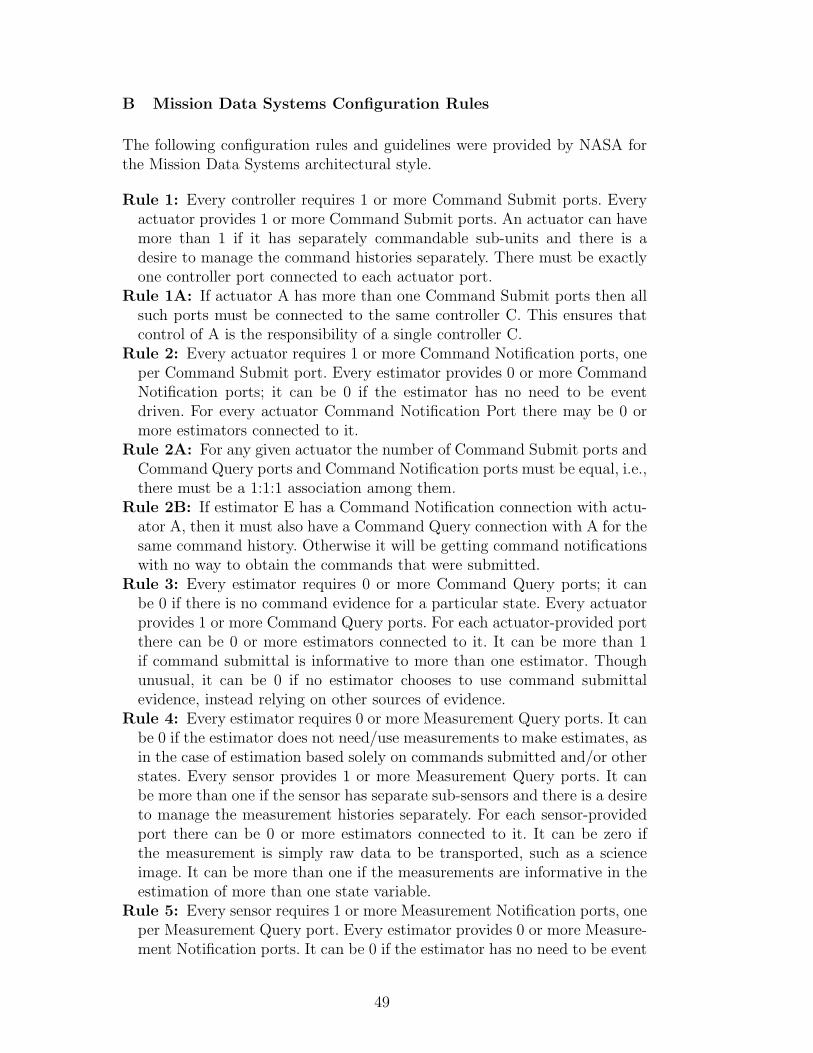
B Mission Data Systems Configuration Rules
The following configuration rules and guidelines were provided by NASA forthe Mission Data Systems architectural style.
Rule 1: Every controller requires 1 or more Command Submit ports. Everyactuator provides 1 or more Command Submit ports. An actuator can havemore than 1 if it has separately commandable sub-units and there is adesire to manage the command histories separately. There must be exactlyone controller port connected to each actuator port.
Rule 1A: If actuator A has more than one Command Submit ports then allsuch ports must be connected to the same controller C. This ensures thatcontrol of A is the responsibility of a single controller C.
Rule 2: Every actuator requires 1 or more Command Notification ports, oneper Command Submit port. Every estimator provides 0 or more CommandNotification ports; it can be 0 if the estimator has no need to be eventdriven. For every actuator Command Notification Port there may be 0 ormore estimators connected to it.
Rule 2A: For any given actuator the number of Command Submit ports andCommand Query ports and Command Notification ports must be equal, i.e.,there must be a 1:1:1 association among them.
Rule 2B: If estimator E has a Command Notification connection with actu-ator A, then it must also have a Command Query connection with A for thesame command history. Otherwise it will be getting command notificationswith no way to obtain the commands that were submitted.
Rule 3: Every estimator requires 0 or more Command Query ports; it canbe 0 if there is no command evidence for a particular state. Every actuatorprovides 1 or more Command Query ports. For each actuator-provided portthere can be 0 or more estimators connected to it. It can be more than 1if command submittal is informative to more than one estimator. Thoughunusual, it can be 0 if no estimator chooses to use command submittalevidence, instead relying on other sources of evidence.
Rule 4: Every estimator requires 0 or more Measurement Query ports. It canbe 0 if the estimator does not need/use measurements to make estimates, asin the case of estimation based solely on commands submitted and/or otherstates. Every sensor provides 1 or more Measurement Query ports. It canbe more than one if the sensor has separate sub-sensors and there is a desireto manage the measurement histories separately. For each sensor-providedport there can be 0 or more estimators connected to it. It can be zero ifthe measurement is simply raw data to be transported, such as a scienceimage. It can be more than one if the measurements are informative in theestimation of more than one state variable.
Rule 5: Every sensor requires 1 or more Measurement Notification ports, oneper Measurement Query port. Every estimator provides 0 or more Measure-ment Notification ports. It can be 0 if the estimator has no need to be event
49

driven. For every sensor port there may be 0 or more estimators connectedto it.
Rule 5A: For any given sensor the number of Measurement Notification portsmust equal the number of Measurement Query ports.
Rule 5B: If estimator E has a Command Notification connection with ac-tuator A, then E must also also have a Command Query connection withA for the same command history. Otherwise it will be getting commandnotifications with no way to obtain the commands that were submitted.
Rule 6: Every state variable provides exactly 1 State Query port. There canbe any number of components connected to that port. It would be suspiciousif there were no connections at all, but it is valid for states that are estimatedpurely for transport to another deployment.
Rule 7: Every estimator requires 1 or more State Update ports, one per statevariable that it estimates. Every state variable provides exactly 1 StateUpdate port, and has exactly 1 estimator connected to it.
Rule 8: Every state variable requires exactly 1 State Notification port andcan have any number of other components connected to it.
Rule 8A: If component C has a connection to the State Notification port ofstate variable S, then C must also have a connection to the State Queryport of S. Otherwise, C will be getting notifications with no way to obtainthe updated state.
Rule 9: Every executable component provides exactly 1 Execute port. Theremust be a 1-to-1 association of thread scheduler ports to executable com-ponent ports.
Rule 10: No two ports of a component should be connected to the sametarget port. This could happen due to a cut-and-paste error where, say, acontroller has two State Query ports connected to the same state variable.
Rule 11: Every connection must be ”property compatible.” System engineerswill specify properties at four levels: component type, component instance,port type, and port instance. For example, suppose that there is a singleposition and heading controller for the six wheels of a rover, and that itrequires 12 Command Submit ports (6 for steering and 6 for driving). Hereare examples of properties at each of the four levels:• component type: property = executable, controller• component instance: property = position and heading• port type: property = steering, multiplicity=1• port instance: property = left-frontThus, in attempting a connection, property checking at the port instancewould prevent a left/right error, and property checking at the port typewould prevent a steering/driving error as well as a multiplicity error (0connections where exactly 1 is required).
Note for Consideration: There ought to be enough information specifiedin properties such that there is only one valid arrangement of connections(or that all possible arrangements are equivalent). Otherwise, system en-gineers are leaving something unsaid, open to creative interpretation by
50

others downstream in the development process. Thus, we should view theproperty information as part of a prescription. In addition to the prescrip-tion, we need to specify requirements on evolution so that thread manage-ment (for example) while creating, configuring, and connecting componentsis specified.
Rule 12: There are several ”don’t do this” kind of rules. For example, neverconnect a controller to a sensor (because then it is doing its own privateestimation), and never connect an estimator to a Command Submit port ofan actuator (because only a controller is allowed to submit commands).
Rule 13: For every estimator/controller pair where the controller controls astate variable that is estimated by that estimator, the order of dispatchfor the pair of executables must be deterministic. If either the estimator orcontroller or both are connected to executable hardware adapter(s), then thehardware adapter(s) must be included in the deterministic ordering check.
51

C Abstract Syntax of Acme Language
The following abstract syntax is a subset of Acme language that is trans-latable to Alloy using the technique presented in this paper.
Style ::= style id [ extends id+ ] Decl∗
Decl ::=
fun id ( ( id: Type )∗ ): Type Expr| type id extends ElemType+ Decl∗
| type id = [ ( id: PropType )∗ ]| element id: ElemType| property id: PropType| attachment id.id to id.id| invariant Expr
Expr ::=
unary op Expr| Expr binary op Expr| Xid (Expr∗ )| Xid| id| Expr.id| Expr.reference| select id [ : Type ] in Expr | Expr| collect id.id in Expr | Expr| {Expr∗ }| <Expr∗ >| quantifier id [ : Type ] in Expr | Expr| integer
ElemType ::= Xid | element | component | connector | port | rolePropType ::= Xid | int | set int | seq int
Type ::= ElemType | PropType | set ElemType | systemXid ::= [ id /] id
id ::= identifier
unary op := ! | -binary op := or | -> | <-> | and | == | != | < | > | <= | >= | + | - | * | / | %reference := components | connectors | ports | roles | attachedports | attachedroles
quantifier := forall | exists | unique
52