analysis on the hull girder ultimate strength … · analysis on the hull girder ultimate strength...
TRANSCRIPT
ANALYSIS ON THE HULL GIRDER ULTIMATE STRENGTH OF A BULK CARRIER USING SIMPLIFIED METHOD BASED ON AN INCREMENTAL
– ITERATIVE APPROACH Özgür Özgüç Det Norske Veritas AS Offshore Classification South East Asia 10 Science Park Drive 118224 Singapore E-mail: [email protected] N.D.P. Barltrop Dept. of Naval Architecture and Marine Engineering, Universities of Glasgow and Strathclyde, Henry Dyer Building, 100 Montrose Street, Glasgow G4 0LZ, UK E-mail: [email protected]
ABSTRACT
The hull girder ultimate strength of a typical bulk carrier is analyzed using simplified method based on
an incremental – iterative approach. First, vertical bending moment is examined by seven different
methods. The moment versus curvature curves and the values of the ultimate longitudinal moments at
collapse states are determined for both hogging and sagging cases. Secondly, the ultimate strength
under coupled vertical and horizontal bending moment is accounted. An interaction curve is obtained
corresponding to the results of series of calculation for the ship hull subject to bending conditions with
different angles of curvature. It is found that the interaction curve is asymmetrical because the hull
cross-section is not symmetrical with respect to horizontal axis and the structural response of the
elements under compression is different from that under tension due to nonlinearity caused by
buckling. The angles of the resultant bending moment vector and that of the curvature vector are
different in investigated cases. The interaction design equations proposed by other researches are also
addressed to discuss the results presented by this study.

1 INTRODUCTION
A ship hull is a structure composed of plating stiffened by girders and stiffeners. The hull is subject to
loading generated by hull weight, cargo, equipment etc. and buoyancy force. The loading cause vertical
and horizontal bending moments, vertical and horizontal shear forces, and torsional moment. Essential
in estimation of the hull strength is the vertical bending moment as generating the largest stresses in the
ship structures, especially in the middle part of the ship hull. However, a ship is in general subjected to
both vertical and horizontal bending moments, particularly in a rough sea with significant roll motions.
The ultimate hull girder strength under horizontal bending is generally higher than vertical bending.
This is because the ship’s breadth is usually larger than its depth.
Yao et al., (1994) studied on the ultimate hull girder strength interaction relationship under combined
vertical and horizontal bending for double hull tanker. Mansour et al., (1995) presented an empirical
interaction equations based on the results of calculations of one tanker, one container ship and one
cruiser. Paik et al., (1996) discussed the ultimate hull girder strength under combined vertical and
horizontal bending moment using ALPS/ISUM program for eleven vessels: five tankers, two bulk
carriers, two container vessels and two cruisers. It was found that the ultimate strength interaction
relationship for combined loading was unaffected by the level of initial imperfections, even though the
ultimate strengths itself would be reduced as the initial imperfections increase. The simple expression
was proposed, regardless of initial imperfection level. Another interaction equation was proposed by
Gordo and Guedes Soares, (1996, 1997) based on the results for five tankers and six container ships.
Rizzuto, (1997) also discussed on this subject. Hu et al., (2001) analyzed the ultimate longitudinal
strength of a typical bulk carrier by using a simplified method under combined vertical and horizontal
bending moments. An interaction equation suitable for bulk carrier was proposed based on the results
of the investigated ship.
Ozguc et al., (2006a, 2005b) have calculated the ultimate coupled vertical and horizontal bending
moment capacity on single side skin and double side skin bulk carriers which corresponding to intact
and investigated various collision damage scenarios, in which a progressive collapse analysis based on
Smith’s method was carried out. It has been noted that the combined effect of the vertical and
horizontal bending moments is important, especially when the ship is damaged.
Ozguc et al., (2007a) have presented the most extensive investigation of the hull girder ultimate
strength under coupled bending moment. The main objective of the study was to develop hull girder
ultimate strength interaction relationships useful for the ship designs subject to a combination of
vertical and horizontal bending moments, where the ordinary Smith’s method was employed using a
developed computer code NEPTUNE with average stress – average strain relationship of element. The
procedure adopted was applied to analyze on the seventeen ships such as nine tankers, five bulk
carriers, one general cargo and two container vessels. The findings obtained were used to develop a
rapid procedure for the assessment of the ultimate capacity of the hull girder.
In this paper, the hull girder ultimate strength of a typical bulk carrier is analyzed using simplified
method based on an incremental – iterative approach. First, vertical bending moment is examined by
seven different methods. The moment versus curvature curves and the values of the ultimate
longitudinal moments at collapse states are determined for both hogging and sagging cases. Secondly,
the ultimate strength under coupled vertical and horizontal bending moment is accounted. An
interaction curve is obtained corresponding to the results of series of calculation for the ship hull
subject to bending conditions with different angles of curvature. It is found that the interaction curve is
asymmetrical because the hull cross-section is not symmetrical with respect to horizontal axis and the
structural response of the elements under compression is different from that under tension due to
nonlinearity caused by buckling. The angles of the resultant bending moment vector and that of the
curvature vector are different in investigated cases. The interaction design equations proposed by other
researches are also addressed to discuss the results presented by this study.
2 FEATURES OF THE METHOD
A progressive collapse analysis based on the Smith method (1977) is carried out in this study. In this
approach, the ultimate hull girder bending moment capacity is defined as the peak value of the curve
with vertical bending moment versus the curvature of the ship cross section. The curve is obtained by
means of an incremental – iterative approach. Each step of the incremental procedure is represented by
the calculation of the bending moment, which acts on the hull transverse section as the effect of an
imposed curvature. For each step, the curvature value is obtained by summing an increment of
curvature to the value relevant to the previous step. This increment of the curvature corresponds to an
increment of the rotation angle of the hull girder transverse section around its horizontal axis. This
rotation induces axial strains in each hull structural element, whose value depends on the position of
the element. In hogging condition, the structural elements above the neutral axis are lengthened, while
the elements below the neutral axis are shortened. Vice-versa in sagging condition.
The stress induced in each structural element by the strain is obtained from the load-end shortening
curve of the element, which takes into account the behavior of the element in the non-linear elastic-
plastic domain. The distribution of the stresses induced in all the elements composing the hull
transverse section determines, for each step, a variation of the neutral axis position, since the
relationship is non-linear. The new position of the neutral axis relevant to the step considered is
obtained by means of an iterative process, imposing the equilibrium among the stresses acting in all the
hull elements. Once the position of the neutral axis position of the neutral axis is known and the
relevant stress distribution in the section structural elements is obtained, the bending moment of the
section around the new position of the neutral axis, which corresponds to the curvature imposed in the
step considered, is obtained by summing the contribution given by each element stress. In applying the
procedure described in above, the following assumption are generally made,
• The ultimate strength is calculated at the hull transverse sections between two adjacent
transverse webs
• The hull girder transverse section remains plane during each curvature increment
• The hull material has an elastic-plastic behavior
• The hull girder transverse section is divided into a set of elements, which are considered to act
independently
• Overall grillage collapse is avoided by sufficiently strong transverse frames
3 THE FOLLOWED STEPS
The vertical bending moment is indeed the most important load effect when considering the hull girder
collapse. However, in many types of ships, the combined effect of the vertical and the horizontal
bending moments is important. It is well known the basic equations that relate the applied vertical and
horizontal bending moments to the longitudinal stress are very simple and may be summarized;
y
iy
x
ixi I
xMI
yM ..−=σ (1)
or it may be expressed as a function of the total moment by:
y
i
x
ii
Ix
Iy
Mϕϕσ sin.cos.
−= (2)
Where ϕ is the angle that the bending moment vector makes with the baseline, and xi and yi are the
coordinates of the element i in the referential located in any point of the neutral axis. For given points
of the cross section, this relation is constant until the yield stress of the material is reached in any point
of the section. Once the cases mentioned above occur, the neutral axis moves away from its original
position and thus the constancy of the relation may be broken. Similarly, the relation between the angle
of the resultant bending moment vector ϕ and the angle of the curvature vector θ is constant in the
linear elastic range. This relation may be express by:
θϕ tgII
tgx
y= (3)
When the curvature is increased the angle changes slightly towards the neutral axis, but this shift
becomes very quick for curvatures near the buckling of the bottom and side plating, which corresponds
to the maximum horizontal component of the bending moment. The moment vector moves its direction

towards the neutral axis until the maximum of the vertical component, and even further that that,
because of the unloading in the horizontal moment. This behavior is shown in Figure 1.
Figure 1 Initial and at collapse position of the neutral axis under combined bending moment
The most general case corresponds to that in which the ship is subjected to curvature in the x and y
directions respectively denoted as Cx, Cy. The overall curvature C is related to these two components
by:
22yx CCC += (4)
Or
θcos.CCx = and θsin.CC y = (5)
adopting the right-hand rule, where θ is the angle between the neutral axis and the x-axis and is
related to the components of the curvature by:
x
y
CC
tg =θ (6)
The strain at the centroid of an element i is iε which depends on its position and on the hull curvature,
as given by:
ygixgii CxCy .. −=ε (7)
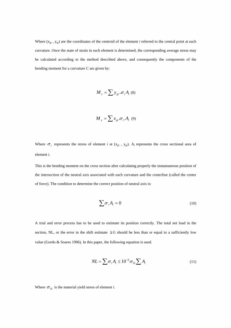
Where (xgi , ygi) are the coordinates of the centroid of the element i referred to the central point at each
curvature. Once the state of strain in each element is determined, the corresponding average stress may
be calculated according to the method described above, and consequently the components of the
bending moment for a curvature C are given by:
iigix AyM σ∑= .. (8)
∑= iigiy AxM ..σ (9)
Where iσ represents the stress of element i at (xgi , ygi). Ai represents the cross sectional area of
element i.
This is the bending moment on the cross section after calculating properly the instantaneous position of
the intersection of the neutral axis associated with each curvature and the centerline (called the center
of force). The condition to determine the correct position of neutral axis is:
0=∑ ii Aσ (10)
A trial and error process has to be used to estimate its position correctly. The total net load in the
section, NL, or the error in the shift estimate ΔG should be less than or equal to a sufficiently low
value (Gordo & Soares 1996). In this paper, the following equation is used.
∑∑ −≤= iiii AANL 0610 σσ (11)
Where i0σ is the material yield stress of element i.
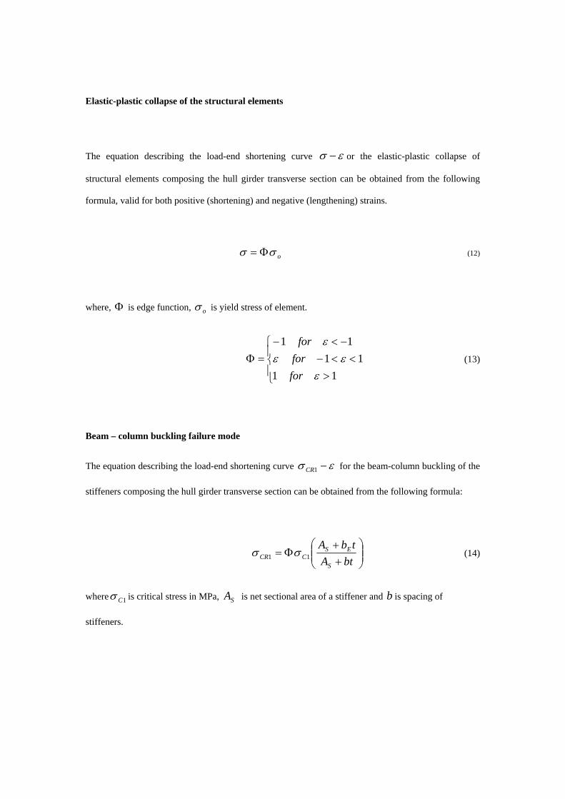
Elastic-plastic collapse of the structural elements
The equation describing the load-end shortening curve εσ − or the elastic-plastic collapse of
structural elements composing the hull girder transverse section can be obtained from the following
formula, valid for both positive (shortening) and negative (lengthening) strains.
oσσ Φ= (12)
where, is edge function, Φ oσ is yield stress of element.
⎪⎩
⎪⎨
⎧
><<−
−<−=Φ
1111
11
εεε
ε
forfor
for (13)
Beam – column buckling failure mode
The equation describing the load-end shortening curve εσ −1CR for the beam-column buckling of the
stiffeners composing the hull girder transverse section can be obtained from the following formula:
⎟⎟⎠
⎞⎜⎜⎝
⎛++
Φ=btA
tbA
S
ESCCR 11 σσ (14)
where 1Cσ is critical stress in MPa, is net sectional area of a stiffener and b is spacing of
stiffeners.
SA
⎪⎪⎩
⎪⎪⎨
⎧
>⎟⎟⎠
⎞⎜⎜⎝
⎛ Φ−
≤
=ε
σσ
σεσ
σ
εσ
σεσ
σ
241
2
11
11
1o
EE
oo
oE
E
C
for
for (15)
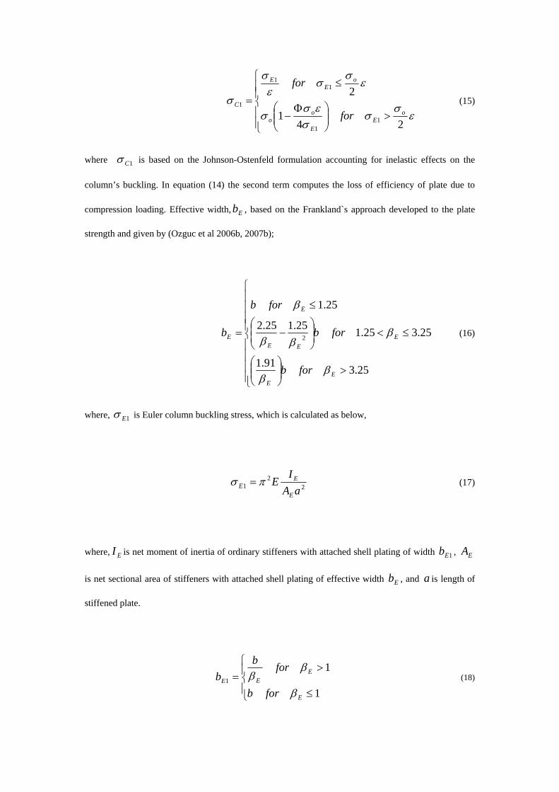
where 1Cσ is based on the Johnson-Ostenfeld formulation accounting for inelastic effects on the
column’s buckling. In equation (14) the second term computes the loss of efficiency of plate due to
compression loading. Effective width, , based on the Frankland`s approach developed to the plate
strength and given by (Ozguc et al 2006b, 2007b);
Eb
⎪⎪⎪⎪
⎩
⎪⎪⎪⎪
⎨
⎧
>⎟⎟⎠
⎞⎜⎜⎝
⎛
≤<⎟⎟⎠
⎞⎜⎜⎝
⎛−
≤
=
25.391.1
25.325.125.125.2
25.1
2
EE
EEE
E
E
forb
forb
forb
b
ββ
βββ
β
(16)
where, 1Eσ is Euler column buckling stress, which is calculated as below,
22
1 aAIEE
EE πσ = (17)
where, is net moment of inertia of ordinary stiffeners with attached shell plating of width ,
is net sectional area of stiffeners with attached shell plating of effective width , and is length of
stiffened plate.
EI 1Eb EA
Eb a
⎪⎩
⎪⎨
⎧
≤
>=
1
11
E
EEE
forb
forbb
β
ββ (18)
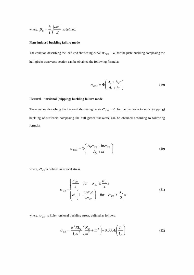
where, Et
b oE
εσβ = is defined.
Plate induced buckling failure mode
The equation describing the load-end shortening curve εσ −2CR for the plate buckling composing the
hull girder transverse section can be obtained the following formula:
⎟⎟⎠
⎞⎜⎜⎝
⎛++
Φ=btA
tbA
S
ESCR2σ (19)
Flexural – torsional (tripping) buckling failure mode
The equation describing the load-end shortening curve εσ −3CR for the flexural – torsional (tripping)
buckling of stiffeners composing the hull girder transverse can be obtained according to following
formula:
⎟⎟⎠
⎞⎜⎜⎝
⎛++
Φ=btAbtA
S
CPCSCR
σσσ 3
3 (20)
where, 3Cσ is defined as critical stress.
⎪⎪⎩
⎪⎪⎨
⎧
>⎟⎟⎠
⎞⎜⎜⎝
⎛ Φ−
≤
=ε
σσ
σεσ
σ
εσ
σεσ
σ
241
2
33
33
3o
EE
oo
oE
E
C
for
for (21)
where, 3Eσ is Euler torsional buckling stress, defined as follows.
⎟⎟⎠
⎞⎜⎜⎝
⎛+⎟
⎠⎞
⎜⎝⎛ +=
P
tC
P
WE I
IEm
mK
aIEI
385.0222
2
3π
σ (22)
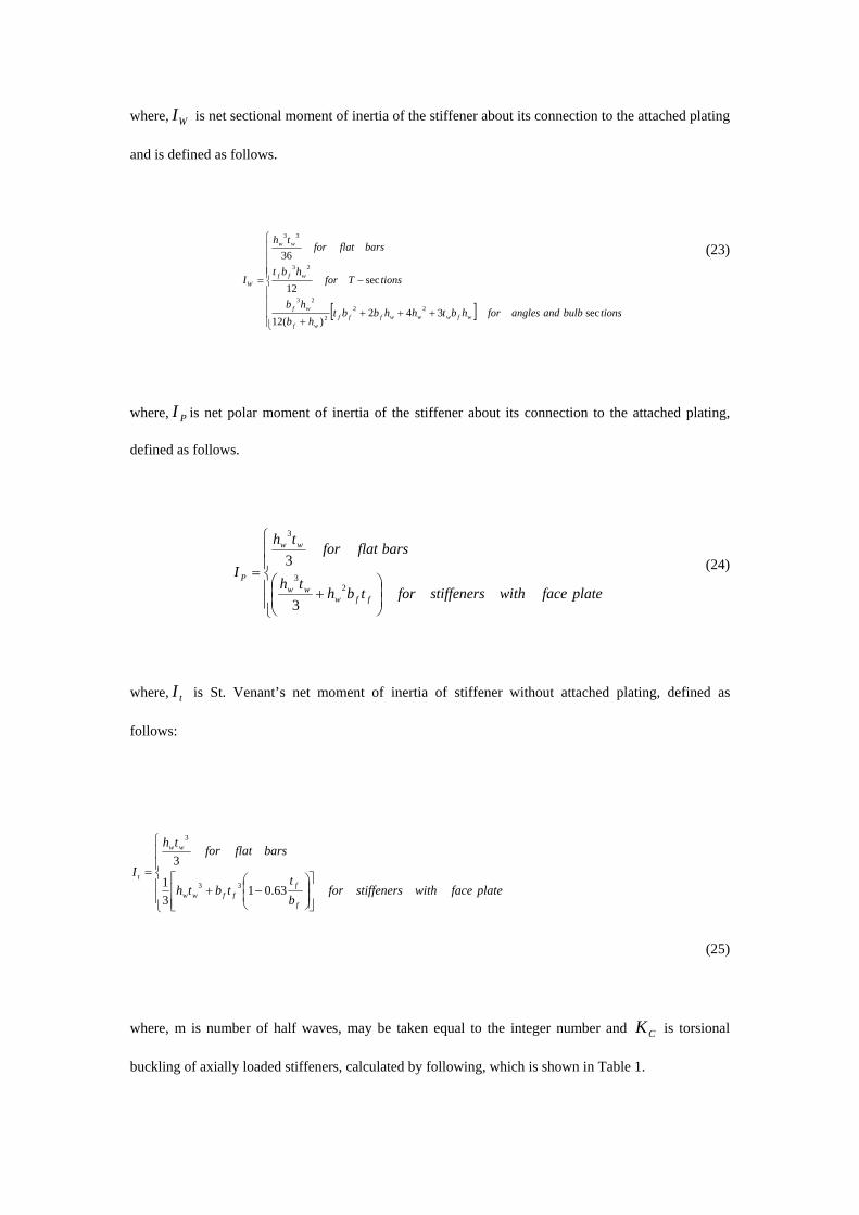
where, is net sectional moment of inertia of the stiffener about its connection to the attached plating
and is defined as follows.
WI
[ ]⎪⎪⎪⎪
⎩
⎪⎪⎪⎪
⎨
⎧
++++
−=
tionsbulbandanglesforhbthhbbthb
hb
tionsTforhbt
barsflatforth
I
wfwwwfffwf
wf
wff
ww
W
sec342)(12
sec12
36
222
23
23
33
(23)
where, is net polar moment of inertia of the stiffener about its connection to the attached plating,
defined as follows.
PI
⎪⎪
⎩
⎪⎪
⎨
⎧
⎟⎟⎠
⎞⎜⎜⎝
⎛+
=platefacewithstiffenersfortbh
th
barsflatforth
I
ffwww
ww
P2
3
3
3
3 (24)
where, is St. Venant’s net moment of inertia of stiffener without attached plating, defined as
follows:
tI
⎪⎪
⎩
⎪⎪
⎨
⎧
⎥⎥⎦
⎤
⎢⎢⎣
⎡⎟⎟⎠
⎞⎜⎜⎝
⎛−+
=platefacewithstiffenersfor
bt
tbth
barsflatforth
I
f
fffww
ww
t
63.0131
3
33
3
(25)
where, m is number of half waves, may be taken equal to the integer number and is torsional
buckling of axially loaded stiffeners, calculated by following, which is shown in Table 1.
CK
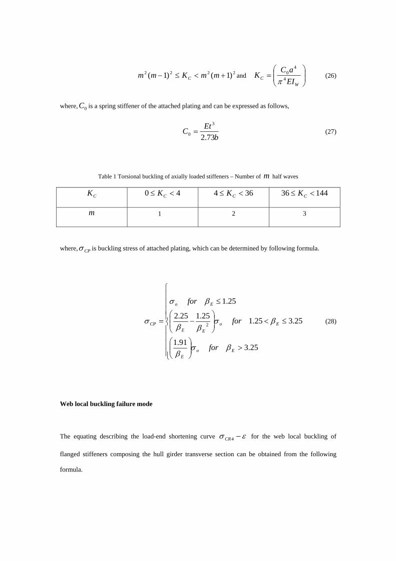
2222 )1()1( +<≤− mmKmm C and ⎟⎟⎠
⎞⎜⎜⎝
⎛=
WC EI
aCK 4
40
π (26)
where, is a spring stiffener of the attached plating and can be expressed as follows, 0C
bEtC73.2
3
0 = (27)
Table 1 Torsional buckling of axially loaded stiffeners – Number of m half waves
CK 40 <≤ CK 364 <≤ CK 14436 <≤ CK
m 1 2 3
where, CPσ is buckling stress of attached plating, which can be determined by following formula.
⎪⎪⎪⎪
⎩
⎪⎪⎪⎪
⎨
⎧
>⎟⎟⎠
⎞⎜⎜⎝
⎛
≤<⎟⎟⎠
⎞⎜⎜⎝
⎛−
≤
=
25.391.1
25.325.125.125.2
25.1
2
EoE
EoEE
Eo
CP
for
for
for
βσβ
βσββ
βσ
σ (28)
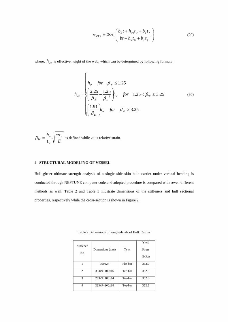
Web local buckling failure mode
The equating describing the load-end shortening curve εσ −4CR for the web local buckling of
flanged stiffeners composing the hull girder transverse section can be obtained from the following
formula.
⎟⎟⎠
⎞⎜⎜⎝
⎛
++
++Φ=
ffww
ffwweEoCR tbthbt
tbthtbσσ 4 (29)
where, is effective height of the web, which can be determined by following formula: weh
⎪⎪⎪⎪
⎩
⎪⎪⎪⎪
⎨
⎧
>⎟⎟⎠
⎞⎜⎜⎝
⎛
≤<⎟⎟⎠
⎞⎜⎜⎝
⎛−
≤
=
25.391.1
25.325.125.125.2
25.1
2
WwE
WwEE
Ww
we
forh
forh
forh
h
ββ
βββ
β
(30)
Eth o
w
wW
εσβ = is defined while ε is relative strain.
4 STRUCTURAL MODELING OF VESSEL
Hull girder ultimate strength analysis of a single side skin bulk carrier under vertical bending is
conducted through NEPTUNE computer code and adopted procedure is compared with seven different
methods as well. Table 2 and Table 3 illustrate dimensions of the stiffeners and hull sectional
properties, respectively while the cross-section is shown in Figure 2.
Table 2 Dimensions of longitudinals of Bulk Carrier
Stiffener
No Dimensions (mm) Type
Yield
Stress
(MPa)
1 390x27 Flat-bar 392.0
2 333x9+100x16 Tee-bar 352.8
3 283x9+100x14 Tee-bar 352.8
4 283x9+100x18 Tee-bar 352.8
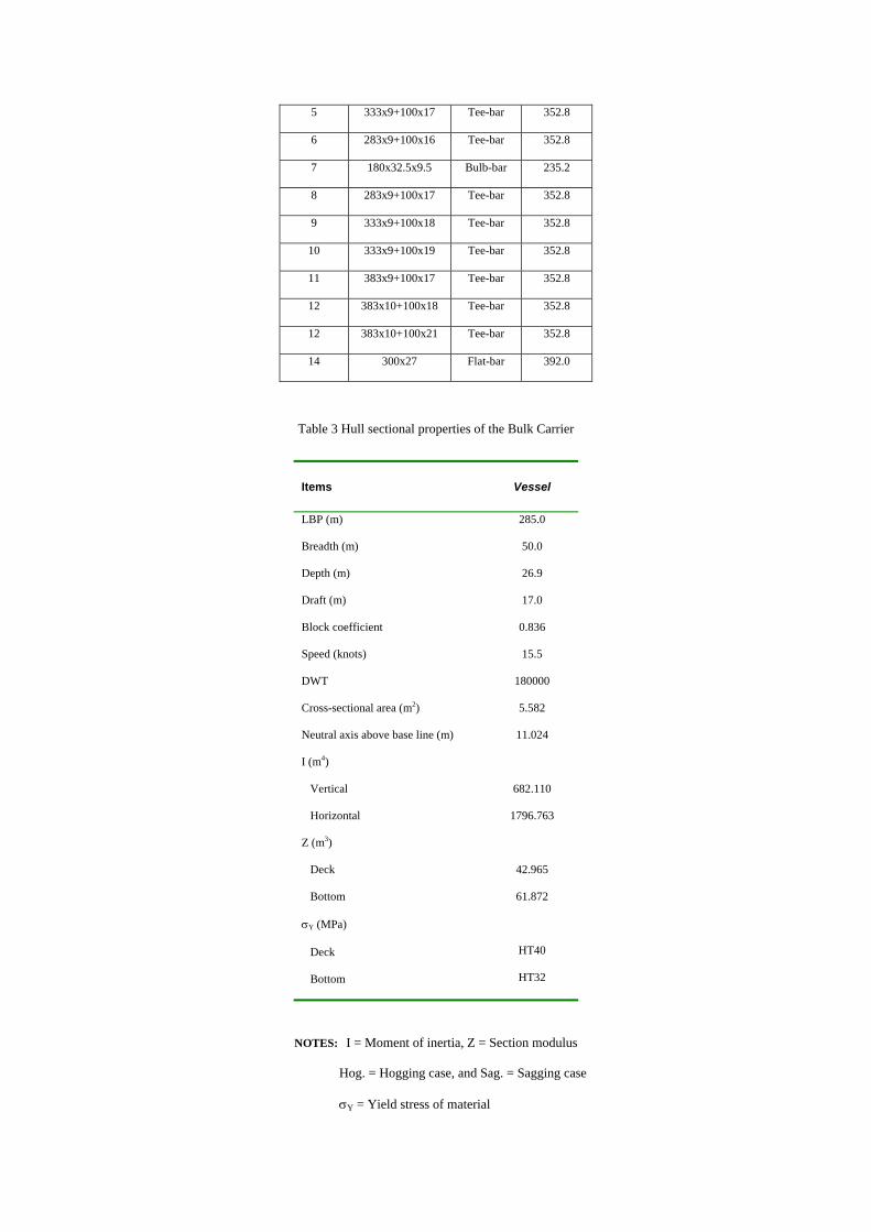
5 333x9+100x17 Tee-bar 352.8
6 283x9+100x16 Tee-bar 352.8
7 180x32.5x9.5 Bulb-bar 235.2
8 283x9+100x17 Tee-bar 352.8
9 333x9+100x18 Tee-bar 352.8
10 333x9+100x19 Tee-bar 352.8
11 383x9+100x17 Tee-bar 352.8
12 383x10+100x18 Tee-bar 352.8
12 383x10+100x21 Tee-bar 352.8
14 300x27 Flat-bar 392.0
Table 3 Hull sectional properties of the Bulk Carrier
Items Vessel
LBP (m) 285.0
Breadth (m) 50.0
Depth (m) 26.9
Draft (m) 17.0
Block coefficient 0.836
Speed (knots) 15.5
DWT 180000
Cross-sectional area (m2) 5.582
Neutral axis above base line (m) 11.024
I (m4)
Vertical
Horizontal
682.110
1796.763
Z (m3)
Deck
Bottom
42.965
61.872
σY (MPa)
Deck
Bottom
HT40
HT32
NOTES: I = Moment of inertia, Z = Section modulus
Hog. = Hogging case, and Sag. = Sagging case
σY = Yield stress of material

5 CALCULATED RESULTS
The calculated results of ultimate hull girder strength under only vertical bending are presented in
Table 4. The items in the tables are as follows,
yI : Moment of inertia with respect to horizontal neutral axis, in m4
Gz : Location of neutral axis above keel under vertical bending, in m
PM : Fully plastic bending moment of cross-section, in MN.m
YSM : Initial yield strength of deck, in MN.m
YHM : Initial yield strength of bottom, in MN.m
BSM : Local buckling strength of deck, in MN.m
BHM : Local buckling strength of bottom, in MN.m
USM : Ultimate bending moment of cross-section under sagging, in MN.m
UHM : Ultimate bending moment of cross-section under hogging, in MN.m
(1): With small initial deflection without welding residual stress, Case 1
(2): With specified initial deflection and welding residual stress, Case 2

Figure 2 Cross-section of single side skin bulk carrier (Yao et al., 2000)
Table 4 Ultimate hull girder strength of bulk carrier under only vertical bending component carrier (Yao et al., 2000)
Items Chen Cho Masaoka Rigo
(2) Soares Yao
Present
Study
Iy 687.87 693.44 689.80 702.48 679.31 682.50 682.11
Zg 11.20 11.06 11.03 10.66 11.15 10.87 11.02
MP 20.87 19.90 19.86 20.03 19.64 20.12 20.22
MYS 15.82 15.64 15.53 15.45 15.41 15.21 15.19
MYH 21.58 21.83 21.79 23.04 21.20 21.91 19.41
MBS 13.19 13.05 12.95 12.89 12.85 12.79 12.06
MBH 16.43 16.63 16.59 17.55 16.14 16.68 16.20
MUS-1 15.35 14.40 16.82 - 13.72 15.67 14.79
MUH- 18.71 19.55 18.90 - 17.43 17.78 17.83

1
MUS-2 15.20 13.69 16.02 14.84 - 14.45 14.19
MUH-
2
19.06 18.99 18.56 17.08 - 17.36 17.34
MOMENT (x 1000 MN-m)
The moment-curvature relationships obtained by different methods for Case (2) are plotted in Figure 3
and Figure 4.
Bulk Carrier (Case 2) in Hogging
0
5
10
15
20
25
0.00 0.20 0.40 0.60Curvature (1/m)
Bend
ing
Mom
ent (
MN
m)
Yao Rigo (2) Masaoka Cho Chen Present study
x10-3
x103
Figure 3 Moment curvature relationships for Bulk Carrier under only vertical bending component for Hogging
condition

Bulk Carrier (Case 2) in Sagging
0
5
10
15
20
0.00 0.20 0.40 0.60Curvature (1/m)
Ben
ding
Mom
ent (
MN
m)
Yao Rigo (2) Masaoka Cho Chen Present study
x10-3
x103
Figure 4 Moment curvature relationships for Bulk Carrier under only vertical bending component for Sagging
condition
The simplified procedure used in this work to predict the behavior of the hull girder under vertical
bending seems to be quite accurate when the results are compared with those obtained by seven
different approaches.
It is seen that the scatter in the ultimate hull girder strength is not so large especially when the hull is
subject to hogging bending moment. This may be partly because the bottom plate is relatively thick,
and the hull buckling strength is nearly equal to the yield strength. On the other hand, the scatter of the
ultimate hull girder strength in sagging is relatively large. This may be because different methods give
somewhat different buckling strength of the deck, which has in general lighter scantling and is more
sensitive to buckling than the bottom.
The capacity beyond the ultimate strength is somewhat scattering compared to the ultimate hull girder
strength significant reduction in the capacity is not observed with ISUM results (Masaoka and Chen
methods), while it is seen in the Smith’s method using average stress – average strain relationships.
The behavior strongly depends on the element characteristics, namely, whether or not the load
shedding in the elements beyond their ultimate strength is correctly accounted for. Therefore, the

presented ISUM elements seem to have been failed to simulate load-shedding behavior of element.
However, recently more sophisticated elements are proposed and still under development.
To simulate the load shedding (capacity reduction) beyond the ultimate hull girder strength, it is
necessary to account the influences of the localization of yielding and deformation after the ultimate
strength has been reached.
The next point, which should be noticed, is the relationships between initial yielding strength and
calculated hull girder ultimate strength. Even though, there are some exceptional cases, it can be said
that, under sagging case, the initial yielding strength shows relatively good correlation with the hull
girder ultimate and in general gives a little lower estimation value. On the other hand, under the
hogging case, the initial yielding strength is sometimes higher than the fully plastic bending moment.
This is the case when neutral axis of the cross section is located at lower part of the cross-section and
stress based on elastic moment of inertia near the deck is higher than yield stress. For this fictitious
stress distribution is, is higher than . In this case, the initial buckling strength, , gives
a better estimate of the hull girder ultimate strength than in general on the conservative side.
YHM PM BHM
YHM
6 COLLAPSE ANALYSES UNDER COUPLED BENDING
Ships have some particular behavioral problems subject to coupled vertical and horizontal bending
moment due to interactions of their particular geometry. The maximum stresses are normally taken
place at the conjunction between the deck and side under coupled moment. This is mainly because, the
ultimate strength of stiffened plate the slenderness ratios are different from each others; thus different
maximum axial carrying capacity is expected to occur. The ultimate carrying capacity of side structure
is usually lower than that of the deck. As a result, the impact on the vertical and horizontal moment of
these stresses – strain distributions near collapse is different since the side strength is more important
for the horizontal bending while the deck strength is more important for the sagging moment.
The angle of the resultant bending moment vector and the angle of the curvature vector is changing
during the load process. If the direction of one of them is kept constant, the minimum carrying capacity

of the section to sustain the bending moment is obtained at angles near but not equal to the horizontal
bending.
The hull girder ultimate strength of bulk carrier vessel is analyzed under combined vertical and
horizontal bending moments. Interaction curves are obtained from a series of calculation for the hull
bending with different angles of the curvature vector from hogging of vertical bending (the angle of the
curvature vector θ = 0 degree) through horizontal bending (θ = 90 degree) to sagging of the vertical
bending (θ = 180 degree).
0
2
4
6
8
10
12
14
16
18
0.0 0.1 0.2 0.3 0.4 0.5Curvature (1/m)
Bend
ing
Mom
ent (
GN
m)
Horizontal Vertical Resultant
x10-3
Figure 5 Components of bending moment at θ = 20 degree in hogging condition

In Figure 5 the results of bulk carrier are presented in the form of bending moment versus curvature
diagram in terms of resultant, vertical and horizontal components. In the present case at an angle of
curvature vector θ = 20 degree, a collapse of the section is evident in horizontal bending moment at a
curvature of 0.106x10⁻³ 1/m, while vertical bending moment has its maximum value at a curvature of
0.201x10⁻³ 1/m. This is because, the side panels near the bilge collapse first and this collapse is more
important for the horizontal than for the vertical modulus due to the greater reduction in effective
inertia moment about the vertical than about the horizontal axis.
The collapse under the simultaneous action of vertical and horizontal bending moments has been
calculated for the different combinations as reflected in the angle between the neutral axis and the
horizontal axis.
A series of diagrams is presented in Figure 6 to illustrate the behavior and the ultimate capacity of the
analyzed bulk carrier vessels’ in the case of combined bending moment with respect to analyze of
curvature vector. It can be seen that the horizontal component is equal to zero in case of the vertical
bending as the cross section is symmetrical with respect to the vertical axis. Due to lack of symmetry
with respect to the horizontal axis, a non-zero value of the vertical component appears.
-20
-15
-10
-5
0
510
15
20
25
30
0 30 60 90 120 150 180
Angle of curvature vector (degree)
Mom
ent (
GN
m)
Resultant Vertical Horizontal
Figure 6 The magnitude of the moment components with respect to angle of curvature vector

The relationship between the angles of the curvature vector and the angle of the resultant bending
moment vector for the present bulk carrier vessels is plotted in Figure 7. It is seen that it is different in
general cases. The reason for the asymmetry of the curves is that the hull cross-section of the bulk
carrier is not symmetrical about horizontal axis and the behavior of the structural members under
compression is different from that under tension due to the nonlinearity caused by buckling. Therefore,
the angle of the curvature vector and the angle of the resultant bending moment vector are not same in
general cases.
0
30
60
90
120
150
180
0 30 60 90 120 150 180Angle of curvature vector (degree)
Angl
e of
resu
ltant
ben
ding
mom
ent v
ecto
r (d
egre
e)
Figure 7 Relationship between angle of resultant bending moment and angle of curvature vector
For single skin bulk carrier vessel investigated in this study the following characteristics can be drawn
through this investigation.
• When the hull is under horizontal bending, that is, the angle of the curvature vector is θ = 90
degree, the angle of resultant bending moment vector, ϕ , is not equal to 90 degree due to
effect of non-linearity. When θ = 90 degree, there exist both horizontal and vertical bending
moments on the hull cross-section. For the present bulk carrier, when θ = 90 degree, the
horizontal bending moment is 22.931 GNm and vertical bending moment is 2.072 GNm. The
angle of the resultant bending moment is ϕ = 87.65 degree.
• If the hull girder is subjected only to horizontal bending moment, that is, the angle of the
resultant bending moment vector is ϕ = 90 degree, then the angle of the curvature vector is

not necessarily equal to 90 degree. The angle of the curvature vector is θ = 95.08 degree when
ϕ = 90 degree for the investigated bulk carrier vessel.
• The maximum value of the horizontal bending moment occurs neither at θ = 90 degree nor at
ϕ = 90 degree. For Bulk Carrier, the maximum value of the horizontal bending moment takes
place at θ = 71.58 degree and ϕ = 83.18 degree. The maximum value of the horizontal
bending moment is 23.56 GNm. At the moment the horizontal bending moment reaches its
maximum, there exists a vertical bending moment on the hull cross-section, which is 2.823
GNm.
For the ultimate strength interaction relationship between vertical and horizontal bending moments, the
following simple expression was proposed by Paik et al., (1996), regardless of initial imperfection
level.
185.1
=⎟⎟⎠
⎞⎜⎜⎝
⎛+⎟⎟
⎠
⎞⎜⎜⎝
⎛
yu
y
xu
x
MM
MM
(23)
Where, is vertical bending moment, is vertical ultimate bending moment, is horizontal
bending moment and is horizontal ultimate bending moment.
xM xuM yM
yuM
Another interaction equation was proposed by Gordo and Soares, (1997) based on the results for five
tankers and six container ships, which is,
1=⎟⎟⎠
⎞⎜⎜⎝
⎛+⎟⎟
⎠
⎞⎜⎜⎝
⎛a
yu
ya
xu
x
MM
MM
1.50< <1.66 (24) a
Even though interaction equations proposed by Gordo & Soares were not applied to bulk carriers, even
so they have been used in this study.
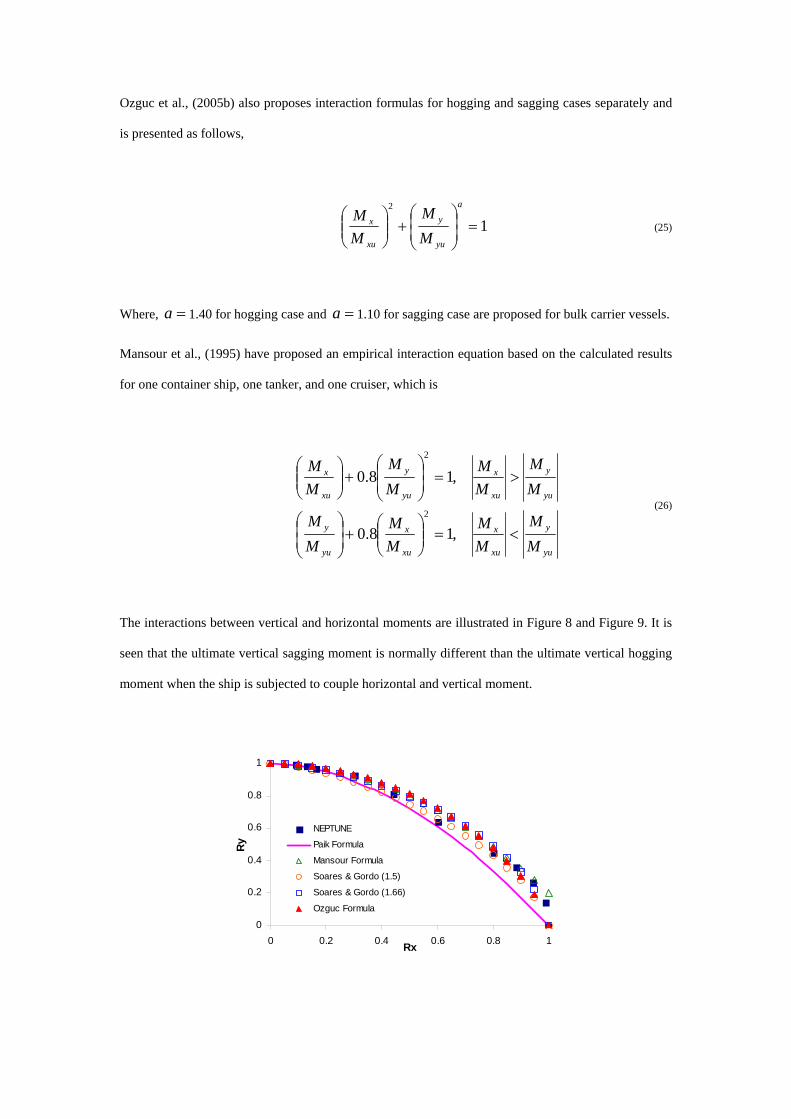
Ozguc et al., (2005b) also proposes interaction formulas for hogging and sagging cases separately and
is presented as follows,
12
=⎟⎟⎠
⎞⎜⎜⎝
⎛+⎟⎟
⎠
⎞⎜⎜⎝
⎛a
yu
y
xu
x
MM
MM
(25)
Where, 1.40 for hogging case and =a =a 1.10 for sagging case are proposed for bulk carrier vessels.
Mansour et al., (1995) have proposed an empirical interaction equation based on the calculated results
for one container ship, one tanker, and one cruiser, which is
yu
y
xu
x
xu
x
yu
y
yu
y
xu
x
yu
y
xu
x
MM
MM
MM
MM
MM
MM
MM
MM
<=⎟⎟⎠
⎞⎜⎜⎝
⎛+⎟
⎟⎠
⎞⎜⎜⎝
⎛
>=⎟⎟⎠
⎞⎜⎜⎝
⎛+⎟⎟
⎠
⎞⎜⎜⎝
⎛
,18.0
,18.0
2
2
(26)
The interactions between vertical and horizontal moments are illustrated in Figure 8 and Figure 9. It is
seen that the ultimate vertical sagging moment is normally different than the ultimate vertical hogging
moment when the ship is subjected to couple horizontal and vertical moment.
0
0.2
0.4
0.6
0.8
1
0 0.2 0.4 0.6 0.8 1Rx
Ry
NEPTUNE
Paik Formula
Mansour Formula
Soares & Gordo (1.5)
Soares & Gordo (1.66)
Ozguc Formula

Figure 8 Interaction curves for bulk carrier under coupled bending moment for hogging condition, Rx and Ry
indicate non-dimensional vertical and horizontal bending moments’ ratio
0
0.2
0.4
0.6
0.8
1
0 0.2 0.4 0.6 0.8 1Rx
Ry
NEPTUNE
Paik Formula
Mansour Formula
Soares & Gordo (1.5)
Soares & Gordo (1.66)
Ozguc Formula
Figure 9 Interaction curves for bulk carrier under coupled bending moment for sagging condition
7 CONCLUSIONS
The simplified method based on the discrete hull cross-section model is a simple and effective method
to estimate the ultimate longitudinal strength of ship hulls. A 180000 DWT capacity single side skin
bulk carrier is analyzed by using a simplified method in this paper. Vertical bending moment is
examined by seven different methods. The moment versus curvature curves and the values of the
ultimate longitudinal moments at collapse states are determined for both hogging and sagging cases.
Some scatters were observed among calculated results applying different methods. On the other hand,
it was shown that a simplified method predicts the ultimate strength very accurately if the assumed
collapse mode is the same as the actual one. The most crucial point for a simplified method is that it is
able to simulate the occurrence of overall buckling as a stiffened plate including tripping of
longitudinal stiffeners.
The primary aim of the this research study was to investigate the characteristics of the ultimate strength
for bulk carrier ship design and to compare simple strength interaction relationships proposed by
researchers for hogging and sagging cases between the two load components that normally act on it,
namely vertical and horizontal bending moment.
It was shown that the ultimate hull strength interaction formulas used in this paper provided reasonably
accurate fits to actual NEPTUNE output. Therefore, the results presented can be extremely useful for
the trend analysis in ship design or in the reliability analysis of hull girder collapse.
The evaluation of the ultimate strength using NEPTUNE is believed to be an adequate estimation of the
ultimate load capacity of the ship. Further refinement using non-linear FE analysis requires
considerably more engineering and computational effort and is not expected to yield substantially
different results
8 ACKNOWLEDGEMENTS
The views expressed in this paper are those of the authors and are not necessarily those of the
institution with which the authors are affiliated
9 REFERENCES
Gordo, J.M., and Guedes Soares, C. (1996). Approximate methods to evaluate the hull girder collapse
strength, Marine Structures, 9(3), 449-470.
Gordo, J.M. and Guedes Soares, C. (1997) Interaction equation for the collapse of tankers and
containership under combined bending moments, Journal of Ship Research, 41: 230-240.
Hu, Y., Zhang, A. and Sun, J. (2001). Analysis on the ultimate longitudinal strength of a bulk carrier by
using a simplified method, Marine Structures, 14: 311-330.
Mansour, A.E., Lin, Y.H. and Paik, J.K. (1995). Ultimate strength of ships under combined vertical and
horizontal moments, Proceedings of 6th International Symposium on Practical Design of Ships and
Mobile Units PRADS’95, Seoul.
Ozguc, O., Das, P.K. and Barltrop, N.D.P. (2006a). A comparative study on the structural integrity of
single and double side skin bulk carriers under collision damage, Marine Structures, 18: 511-549.
Ozguc, O., Das, P.K. and Barltrop, N.D.P. (2007a). Rational interaction design equations for the
ultimate longitudinal strength of tankers, bulk carriers, general cargo and container ships under coupled
bending moment, Journal of Ship Research. (Accepted for publication)

Ozguc, O., Das, P.K. and Barltrop, N.D.P. (2006b). A proposed method to evaluate hull girder ultimate
strength. Journal of Ships & Offshore Structures, 1(4):335-346.
Ozguc, O., Das, P.K. and Barltrop, N.D.P. (2007b). The new simple design equations for the ultimate
compressive strength of imperfect stiffened plates, Ocean Engineering. (In press)
Ozguc, O., Das, P.K. and Barltrop, N.D.P. (2005a). Simplified closed-form interaction formulations for
evaluation of structural response of stiffened plates, International Shipbuilding Progress. (Submitted to
publication)
Ozguc, O., Samuelides, M. and Das, P.K. (2005b). A comparative study on the collision resistance of
single and double side skin bulk carriers, International Congress of International Maritime Association
of the Mediterranean (IMAM), 26-30 September, Lisbon, Portugal.
Paik, J.K., Thayamballi, A.K. and Jung, S.C. (1996). Ultimate strength of ship hulls under combined
vertical bending, horizontal bending, and shearing forces, Trans.SNAME, 104: 31-59.
Rizzuto, E. (1997) Discussion of Committee II.1 Report of ISSC’1997, Proceedings of 13th ISSC,
T.Moan and S.Berge (eds), Pergamon Press – Elseiver Science, 13: 69-71.
Smith, C.S. (1977). Influence of local compressive failure on ultimate longitudinal strength of a ship’s
hull, Proc. Int. Symp. On Practical Design in Shipbuilding, Tokyo, Japan, 73-79.
Yao, T. et al (2000). Ultimate hull girder strength, Proceedings of the 14th International Ship and Offshore Structures Congress
(ISSC), Nagasaki, Japan, 321-391.
Yao, T., Fujikubo, M., Kondo, K. and Nagahama, S. (1994). Progressive collapse behavior of double
hull tanker under longitudinal bending, 4th ISOPE Conference. Osaka, Japan.