analysis of reinforced concrete structure with steel fibers …€¦ · 1 analysis of reinforced...
TRANSCRIPT

1
Analysis of reinforced concrete structure with steel fibers subjected to blast loads
*Raghunandan Kumar1) G R Reddy2) and Sunny Dev3)
1), 3) Department of Civil Engineering, Faculty of Engineering, Christ University,
Bengaluru: 560074 2) Baba Atomic Research Centre, Mumbai
ABSTRACT
Commercial and Public Buildings have been the targets by the terrorists in
recent times to draw attention of the public, as it not only causes severe damage to the structures but also causes danger to human life as well. It may not be possible to predict such acts on the private and public assets, but it is important that commercial and public buildings are analyzed and designed to minimize the damage, if not possible to completely protect them, as it may be uneconomical to do that.
An attempt is made to study the response of the reinforced concrete structure by including steel fibers of varying percentages, when subjected to blast loads at constant standoff distance of 6m and varying the charge weights. The variations of the high strains and the lateral deflections are studied when compared to the normal M25 grade concrete.
In this research, the analysis of Ground + 3 storey reinforced concrete skeletal structure is considered for the analysis. Using PTC CREO 3.0 the 3D modeling of structure and structural elements were generated. HYPERMESH was used for the discretization (meshing) of structure and its elements. Static analysis and blast load analysis was analyzed using ANSYS. The blast load parameters such as equivalent overpressure, reflected pressure and time duration based on typical blast wave phenomena was examined.
Keywords: Blast, RC Structure, TNT, Standoff distance, High strains and steel fiber.
1)
Associate Professor 2)
Professor and Scientist 3)
Graduate Student
2
1. INTRODUCTION
In the recent past, several public buildings and structures all over the world have
been the target of explosions through terrorist activities, which results in loss of precious life in addition to the damage caused to the structure.
Structural loads are an important consideration in the analysis and design of buildings in India. Building codes and Indian standard recommendations require that structures be designed and built to safely resist all actions that they are likely to face during their service life, while remaining fit for use. Minimum loads or actions are specified in these building codes for types of structures, geographic locations, usage and materials of construction. Structural loads are categorized by their originating cause. Generally, the buildings are to be analyzed and designed with the static loading conditions along with the safety factors. But, when the loads are dynamic in nature the response of the structures are different.
The study of reinforced concrete structures subjected to blast loads have gained importance, as conventionally the RC structures are not designed for blast loads, due to the fact that quantifying the magnitude of the blast load is difficult. The blasting of explosives cause near catastrophic impacts on the structure of the building, causing damage to the structural frames both internal as well as external. On the other hand, it also causes loss of life due to the collapse of the structure, chipping of the cladding or spalling of concrete, drifts of the floor and the secondary effects due the damage to the facade and the glazing as well.
Disasters such as the terrorist bombings on the U.S. embassy in Nairobi, Kenya, Dares Salaam, Tanzania in 1998, the Khobar Towers military barracks in Dhahran, Saudi Arabia in 1996, the Murrah Federal Building in Oklahoma City in 1995, and the World Trade Center in New York in 1993 has shown the need for the investigation on the behavior of the structure subjected to blast loads. Various software tools are available for analysis of structures with different approaches subjected to blast loads. The finite element programs available are ANSYS, ABAQUS, ADINA, NASTRAN, NISA, LS-DYNA and others. The finite element program considered for he present investigation is ANSYS software.
1.1 General Principles of Blast Phenomena
In general, the load from the explosions is in the form of pressure. This can be analyzed by using the pressure load methods or detonation simulation methods. The principles from the recommendations of IS: 4991-1968 “Criteria for blast load resistant design of structures for explosions above ground”, it is noted that, in the case of static loads i.e., dead loads and live loads, structural members are exposed to detonation pressure to resist the applied forces by means of internal stresses developed in them. However, the effective loads due to blast, for which self-resistance should be developed in the member depends upon the nonlinear properties of the members. Longer the natural time period of the member, smaller is the effective load for design.
Permitting plastic deformations, which increases the energy absorption has the advantage that the effective time period of the structural elements such as beams,

3
columns and slabs is extended, thereby reducing the effective load for its design. The most serious detonations are on the front elevation of a structure where in the buildings are oriented with the face normal to the path of propagation of wave. However, due to the lack of recognized orientation of future explosion, each side of the building should be considered as the facade of the building. When the blast field surrounds the structure, the variation of pressure that is more than the atmospheric pressure takes place on the front and the rear faces of structure, which tends to tilt, drift and spall. Surface explosions that are short duration with a large amplitude and high frequency excitations induce the surface blasting or ground bursts. As the blast wave travels away from the source, the pressure amplitude decreases, and the duration of the blast load increases.
The type of blasting considered for this study is the blast excitation at a constant setback distance, which is called as standoff distance as illustrated in Fig. 1. The standoff distance cannot be predicted in real life terrorist attacks and at the same time it is impossible to quantify the charge weight of explosive being used. As recommended in the building bylaws, the standoff distance of explosion or the setback for Ground + 3 commercial building is considered for the study.
Fig. 1: Surface Blast Wave with Standoff Distance
Over expansion at the center of the blast generates a vacuum in the source region and a reversal of gas motion occur. The negative pressure region expands outward, causing a negative pressure (below ambient), which trails the positive phase. The pressure of negative phase is usually below the magnitude (absolute value), but longer duration than the positive phase. Burst phase loads are more positively charged then the negative phase coherence, which is often ignored and can be found in T. Ngo (2007) and are illustrated in Fig. 2. Earth explosion or gust would be used to break down hardened structures like bunkers, missile silos, locks, springs, etc. they cause much more waste as in the mushroom cloud. As the detonation takes place at ground level, a lot of facilities are required to be shielded from each other from that of the previous damage and is less than in the case of an air blast.

4
Fig. 2: Typical Blast Wave Propagation
1.2 Structural Response to Blast Loading Based on the manmade explosions that have occurred around the world, to
analyze and design the structures that are able to resist these extreme bursts in a very short time on the structural members and its joints, the deflection and the corresponding strains which are greater than the allowable strains are investigated.
The permissible deflections in the structures are usually in the plastic range of materials. A large quantity of excitation pressure will be absorbed by the structure during the action of explosion, especially by concrete, thus reducing the design strength required significantly below the normal by conventional structural design standard within the elastic range of materials.
The analysis of reinforced concrete structures against the burst loads or a shock wave front, as induced by the detonation of the strong gust of wind is under investigation over a decade now. The analysis of structural performance of blast loading can be complex, because short duration high amplitude nonlinear load frequently exhibits the variation in the failure strains, with varying strains corresponding to the material such as concrete and reinforcing steel.
1.3 Steel Fiber Reinforced Concrete
Steel fibers are included in the concrete matrix to assess high strain rates and the lateral deflections in the structure. Research has shown that the addition of steel fibers in concrete mix improves ductility, hardness, tensile strength, and compressive strength significantly, Mohammed Alias Yusof (2010). Why would we want to add such fibers in concrete? Plain cement concrete is a brittle material and with a low tensile strength and less strain capacity. Fibers distributed randomly into the concrete give the flexibility of division. The properties of hooked end steel fibres are referred from Jeetmull
5
Jaichandlall Pvt Ltd Chennai with aspect ratio of 50. The length of steel fibres is 50mm and diameter is10mm.
Fig. 3: Hooked end steel fibres of aspect ratio 50
1.4 High Strains and Lateral Deflections Under extreme dynamic vibrant conditions, high strains depend upon the
response of the material and high levels of hydrostatic loads results in behavior of the material that varies from what is noticed in normal quasi-static loadings. When the rate of loading is high, the mechanical response of a material is generally different from that of normal loads. In which case, such rate of loading dependence is observed for approximately inelastic materials such as concrete. Concrete also exhibits an enigmatic phenomenon and improves properties against resistance as soon as concrete is loaded at very high rates by adding some of the composite materials such as fibers or designing concrete for higher grades.
The member ductility based on the stress strain curve results in the reinforcing steel undergoing elongation without rise in stress by about 10 to 15 times, the extent required to reach yield point. The stress value then increase in hardening range of strain until a total elongation of approximately 20% to 30% is achieved. This response has benefits beyond routine design level forces for resisting the effects of a blast. Ductility ratio defined as the maximum deflection to the elastic deflection is generally used for interpretation for this effect.
2. REVIEW OF RELATED LITERATURES
A few experimental works have been carried out on the reinforced concrete members with the different types of fibres including high performance polyethylene fibres and micro steel fibres with varying volume fractions into the concrete. The authors Jun Lia et al. 2016 investigated the feasibility of using UHMWPE fibre and hybrid fibres in reinforced concrete subjected to severe blasting loads of 6, 8, 12 kgs of TNT reference charge weight at 1.5 m standoff distance. They observed that the reinforced concrete slabs made of UHMWPE fibre and hybrid fibre material experienced much lesser damage and smaller structural deformation as compared to the normal reinforced concrete slabs.

6
Xiaoshan et al. 2016 have developed a finite element model to determine the FRP (fibre reinforced polymers) strengthened Reinforced Concrete laminated sheets subjected to blast loads. The RC slab panels were tested under a blast load of 0.45 kg of TNT at 0.5m standoff distance above the centre of the panel. Research focused on the performance of improving strength of the members, such as walls to resist against these short duration loads (blast loads).
Saleh H.Alsayedetal. 2016 has worked on the infilled masonry walls by using glass fibered polymer laminated sheets against detonation loads. The author carried out tests on Glass Fibre Reinforced Polymer composite masonry walls to show good potential for retrofitting the un-reinforced masonry walls against extreme blast load conditions and to determine de-bonding effects. The de-bonding effect was the primary criteria after each blast effect on the members, to improve the properties against these dynamic loads and to resist strain and deformations. The methodology adopted for the research was in adding of fibres into the concrete matrix.
Dasari Sudheer Kumar et al. 2016 have assessed the performance of reinforced concrete structural frames subjected to three categories of blast loads by analytical method which are carried out in hydrocode LS-DYNA software including the finite element modelling of structural elements. The researchers observed that failure mechanism at column base results erosion of concrete. A Huge amount of spalling observed at column cover in both beams and columns and it is usually severe on the rear face of a column and also the lateral deflections, then the research was mainly carried out of addition of fibres into the concrete.
Hao et al. 2014 have studied on a new type of steel fibre spiral steel fibre and compared the results with the commonly used hooked end steel fibres subjected to impact load by dropping an impact load of 15.2 kg at a height of 0.5m. They showed that the proposed spiral-shaped steel fibres increases the performance of fibre reinforced concrete beam elements under impact loads. In the recent years there have been a considerable numerical and experimental work conducted to understand and determine relationships of simultaneous ground shock and air blast parameters against impulsive loading.
J.I. Siddiqui et al. 2012 developed a methodology of analysis in order to evaluate the effect of an external explosion on RC containments of other reactors. They established empirical relationships of peak air pressure, peak reflected air blast pressure along the height of the structure, peak ground acceleration, arriving shock of ground shock and air blast pressure reaching the concrete structure and so forth on a reinforced concrete containment scaled model owing to a surface explosion at a definite distance. Tests carried out with TNT (Tri Nitro Toluene) charge weights of 1, 3, 5, 15, 25 and 50 kg and charge distance were varied from 5m to 25m. In 2015 the inventions on new type of fibres such as UHPFRC (Ultra High Performance Fibre Reinforced Concrete) to enhance the mechanical properties.
Juechun Xu et al. 2015 have conducted a series of field tests to investigate the behaviour of UHPFRC columns subjected to blast loading. In total four 0.2 m x 0.2 m x 2.5 m UHPFRC columns were tested under different designed explosions but all at a standoff distance of 1.5 m. Blast tests were also performed on four high strength reinforced concrete (HSRC) columns with the same size and reinforcement as
7
UHPFRC columns to evaluate their behaviour under the same loading conditions. The steel fibres at a dosage 2.5% by volume were used.
Damasceno et al. 2014 have investigated on the behaviour of RC beams with steel fibres subjected to impact loading. They conducted their research on beams of length 1500mm and cross section100mmX200mm by varing the steel fibres percentages. The authors concluded that, addition of 2% of steel fibres improved the tensile strength by 100% and increased modulus of elasticity by 38% when compared to control specimens.
Mohammed Alias Yusof et al. 2010 studied on normal strength steel fibre reinforced concrete subjected to explosive loading and has presented the results of an experimental investigation on the behaviour of plain reinforced concrete and Normal strength steel fibre reinforced concrete panels subjected to explosive loading. The steel fibre reinforced concrete panel containing of 0%, 0.5%, 1%, 1.5% volume fraction and the best performance under explosive loading from 1.5% steel fibre mix. The blast phenomenon based on the typical blast wave propagation as illustrated in Fig.2. The blast load parameters such as overpressure and time duration was adopted for the research by Nitesh N. Moon. 2009.
3. METHODOLOGY
The research was carried out in three different phases. The first and foremost one the literature survey, second phase is the casting of concrete specimens to achieve the inputs such as density, poisons ratio, modulus of elasticity and coefficient of thermal expansion and assign it to the structure in the software and third phase is the analytical investigation of blast load by using nonlinear finite element software. To determine the passive structural response of commercial G+3 building by using different percentage of fibers and to determine high strain rates and lateral deflections at different levels of the building and compared with the static analysis.
Development of finite element model for the surface blast load analysis and the behavior of structure for normal RC structure with static loads and RC structure with different percentages of steel fibers 0.5%, 1%, 1.5% and 2% subjected to blast loads by considering the standoff distance (Z) as constant and varying charge weight (W) of explosion.
The research work is to determine the material properties of M25 concrete and with addition of steel fibers 0.5, 1, 1.5 and 2% such as density, compressive strength, poisons ratio, elasticity modulus or young’s modulus. To study and analyze the finite element model of G+3 storey commercial building for the static loads and dynamic loads such as blast with a constant setback of 6m as standoff distance. To determine the blast equivalent over pressure from the blast waves as blast loads to apply to the structure. To assess the high strains and lateral deflections of reinforced concrete structures with static loads and dynamic blast loads with steel fibers and with charge weights of 5, 6, 8 kg of TNT.
8
4. EXPERIMENTAL AND ANALYTICAL INVESTIGATIONS
The experimental investigations was mainly carried out in two phases, the first phase was casting and testing of concrete specimens with M25 grade of concrete and in addition of steel fibers. Tests on basic materials, concrete mix proportions with steel fibers, and tests on fresh concrete were conducted. Testes were also conducted on steel fibered reinforced hardened concrete after 28 days of curing to determine the density, Poisson’s ratio and young’s modulus.
The second phase of the work involved in obtaining the blast overpressure and time duration parameters based on the typical blast wave propagation illustrated in Fig. 2. The calculation of Peak Overpressure and time duration of explosion based on literatures was considered and determined for three charge weights such as 5, 6 and 8kg of TNT with a constant standoff distance 6m as shown in the Table. 1. The blast parameters were achieved by the graphical representation of confining to TM5-1300 as shown in Fig. 4.
Table. 1: Blast load parameters with different charge weights
Charge Weight of TNT (kg)
Scaled Distance 'Z' (m/kg)
1/3
Reflected Pressure Pro (Mpa)
Blast Over Pressure Pso (Mpa)
Sclaed Arrival Time’Ta (ms)’
Positive Phase Duration ’To (ms)’
Total Duration Td=(Ta+To) sec
5 8.95 0.130 0.055 10.104 4.88 0.01498
6 8.43 0.144 0.0625 9.338 5.31 0.01504
8 7.37 0.172 0.0801 7.707 5.368 0.01306
The tests on hardened concrete were the standard Test Method for static
compression, concrete Poisson’s ratio describing the elastic modulus ratio of strain value and the stress for the hardened concrete at any age. This rule also provides that the elasticity modulus is applicable to the range of the normal operating voltage of 0 to 40% of the final strength of the concrete. The modulus of elasticity is often used for reinforced and non-reinforced structural elements.
9
Fig. 4: Graphical Representation to achieve blast parameters confining to TM 5-1300
The tests conducted on hardened concrete were for Poisson’s ratio and modulus of elasticity by noting the compressive strain with respect to compressive stress at every 10KN load increment as shown in the Fig. 4 and material properties for M25 grade of concrete and M25 concrete with steel fibers of 0.5, 1, 1.5 and 2% variation as illustrated in Table. 2.
Table. 2: Material Properties of Concrete Specimens
Grade of concrete
Poisson's ratio
Modulus of elasticity
N/mm2
Density of material KN/m3
Coefficient of thermal
expansion
M25 0.18 26070 25 10-6/oc
M25 + 0.5% steel fibers
0.23 27386 26.1 10-6/oc
M25 + 1% steel fibers
0.235 28995 27.4 10-6/oc
M25 + 1.5% steel fibers
0.25 29568 27.1 10-6/oc
M25 + 2% steel fibers
0.26 30000 27.105 10-6/oc

10
4.1 Blast Loads on Structure gkhgkjhgkjhgkjgkhgkhghgkjgjhgjhgjgjgjgkkhjkhjgjg To Determine Blast Wave Parameters for a Surface Blast.
The blast load parameters for 5kg charge weight of TNT and 6m standoff distance:
Fig. 4 shows Graph confining to TM5-1300
Z = 6 /(5)1/3
Z = 8.95ft/lbs1/3
Peak reflected overpressure Pr = 20psi = 0.02 ksi =0.02 x 6.895 = 0.137 Mpa
Peak blast equivalent overpressure Pso = 8 psi = 0.008 ksi =0.008 X 6.895 = 0.055 Mpa
Ta/W1/3 = 4.540psi ms/lb1/3 = 4.540 X (11.02)1/3 = 10.104 milliseconds
To/W1/3 = 2.195psi ms/lb1/3 = 2.195 X (11.02)1/3 = 4.88 milliseconds
Td = Ta+ To =10.104 + 4.88 = 0.1498 seconds.
The blast load parameters for 6kg charge weight of TNT and 6m standoff distance:
Fig. 4 shows Graph confining to TM5-1300
Z = 6 /(6)1/3
Z = 8.16ft/lbs1/3
Peak reflected over pressure Pr = 20.75psi = 0.02075ksi = 0.02075 X 6.895 = 0.144Mpa
Peak blast equivalent over pressure Pso = 907 psi = 0.00907 ksi =0.00907 X 6.895 = 0.0625 Mpa.
Ta/W1/3 = 3.95psi ms/lb1/3 = 3.95 X (13.22)1/3 = 9.33 milliseconds.
To/W
1/3 = 2.41psi ms/lb1/3 = 2.41 X (13.22)1/3 = 5.69 milliseconds
Td = Ta + To = 9.33 + 5.39 = 0.1504 seconds.
The blast load parameters for 8kg charge weight of TNT and 6m standoff distance:
Fig. 4 shows Graph confining to TM5-1300
Z = 8 / (6)1/3
11
Z = 7.37ft/lbs1/3
Peak reflected overpressure Pr = 25psi = 0.025 ksi =0.025 * 6.895 = 0.172 Mpa
Peak blast equivalent overpressure Pso = 11.62 psi = 0.01162 ksi =0.01162 X 6.895 = 0.0801 Mpa
Ta/W1/3 = 2.96psi ms/lb1/3 = 2.96 X (17.63)1/3 = 7.70 milliseconds
To/W1/3 = 2.063psi ms/lb1/3 = 2.063 X (17.63)1/3 = 5.368 milliseconds
Td = Ta + To = 7.70 + 5.368 = 0.1306 seconds.
The charge weights of TNT of blast considered for this study was 5kg, 6kg and 8kg respectively for a constant standoff distance of 6m. Peak excitation pressure and the time duration parameters based on the distance from explosion to the structure, and with reference to charge weights the blast load parameters such as scaled distance, reflected pressure from shock wave front, blast equivalent overpressure and time parameters scaled arrival time, positive phase duration and total duration of explosions were calculated represented in the typical blast wave phenomena as illustrated in Fig. 5, Fig. 6, Fig. 7 respectively.
Fig. 5 and Fig. 6: Typical Blast Phenomena of 5kg, 6kg TNT and 6m standoff

12
Fig. 7: Typical Blast Phenomena of 8kg TNT and 6m standoff
5. Finite Element Model
5.1 Structure Modelling
Modeling part of the structure was carried out using software PTC Creo 3.0. Firstly, the modeling of structural members such as beams, columns and slabs were drafted, modeled and then assembled. By using Creo 3.0 the structural elements were modeled in separate files and assembly of files performed. After the geometric modeling of columns with its cross section, the beams and slabs are modeled simultaneously and the columns with respect to the geometry and with respect to its major and minor axis the columns are introduced at its respective positions.
5.2 Finite Element Discretization
The meshing of the structure was done using Hypermesh v 14.0 software. For this structure quad element is considered with a mesh size of 600mm and an aspect ratio of 1:1. Compatibility at each beam column joint was checked. An eight-nodded quadrilateral element of 300 mm size was adopted for the geometric model. For discretization, ruled meshing was considered for the research, it can be assigned by giving the mesh size as input based on the user and adopting a size which is more compatible and assigning it to the elements such as beams, columns and slabs. The compatibility of mesh is based on the elements shape and the size and purely based on the two or more elements where the actual discretization takes place the nodes should act as a single element at joints and assembly of structural members as illustrated in Fig. 8.

13
Fig. 8: 8 noded quadrilateral element meshing for complete structure
5.3 Blast Load Analysis
By using three variations of charge weights the structures were analyzed using Ansys software version 14.5. The structure was modeled considering the nonlinearity in Creo and the three dimensional meshing was discretized in Hypermesh software after the compatibility of meshing for each structural element was checked. The finite element model was exported to Ansys APDL V14.5 in the form of common data base file.
6. Results and Discussions
The high strains and lateral deflections for the results obtained from static load analysis was different from blast load analysis due to the conventional RC structures with normal grades of concrete. Structures are susceptible to damage from explosions, as the magnitudes of loads produced by blasts are significantly more than those of the design loads. The high strains and lateral deflections were determined and compared with the static load analysis of the G+3 commercial structure and structure with fibers and the blast load analysis for the structure with 5, 6 and 8 kg charge weight respectively of TNT (Trinitrotoluene) at 6m constant standoff distance. High strains (HS) and lateral deflections (LD) obtained from the results of static analysis and HS and LD of blast load analysis are then compared. Comparison of the results is made on the blast load analysis of G+3 structure with M25 grade concrete and with inclusion 0.5, 1, 1.5 and 2% of steel fibers. In static analysis results the strains for M25 structure were 0.00201 at column grids C and D at ground and first storey of the building whereas the strains for M25 concrete structure with respect to blast load analysis of 5kg TNT was observed as 0.004654, the increase in the HS’s compared to static load analysis was
14
216% and was observed at column grids A, B and F at base floor, the conventional structure with 5kg TNT as illustrated in Fig. 9 which was more than the allowable strain of concrete 0.003.
The lateral deflections of static analysis M25 structure were less compared to 8kg TNT blast load analysis; the LD for static analysis was 23.06mm and LD for the blast load analysis was 135.4mm respectively. The LD in the static analysis was observed at all storey’s on the application of load and in blast load analysis the LD was observed at facade of the structure due to the blast load.
Fig. 9: Blast Load Analysis for M25 concrete structure with 5kg of TNT
The HS and LD for structure with 0.5% steel fibers with respect to static load analysis is 0.001694 and 20.03mm respectively. From the blast load analysis for structure with 0.5% steel fibers, the HS observed for 8kg of TNT is 0.00539 and LD is 115.85mm. High strains were observed at the rear of the structure at the base and in the ground storey. In the static load analysis it was at the middle section of the building with column grids B, C and D and the displacements were more at the application of loads.
The HS and LD obtained for structure with 1% and 1.5% steel fibers are 0.001628, 0.001546 and 19.25mm and 18.47mm respectively for static loads. The HS and LD for structure with 1% and 1.5% steel fibers with blast load analysis was observed as 0.005184, 0.00492 and 111.34mm, 107.17mm respectively. The HS of static analysis compared with blast analysis is very high and increase in HS was 219%

15
and it is observed at the ground storey columns A1 and A6 at the base. In the static analysis the HS results was observed at the intermediate columns and at the beams column joints based on its spans, where as in blast load analysis it was observed at the rear of the structure at the first storey beam column joints.
Under static loads with 2% steel fibers the HS and LD observed are 0.001487 and 18.19mm respectively. Under blast load analysis for structure with 2% steel fibers the HS and LD for 5kg, 6kg and 8kg of TNT were observed as 0.003467, 0.003739, and 0.004378 and 66.43mm, 74.75mm and 94.27 respectively and the maximum strains were observed for 8kg TNT detonation. When compared with the results obtained with static analysis the strains were very high and though the maximum strain capacity of concrete is 0.003, in static analysis the strains were very less. At the point of strain capacity 0.003 the concrete material tends to yield and the maximum strain was 0.00148 hence the structure was safe and strains were minimal.
From the blast load analysis it was observed that, the strains as well as lateral deflections were very high, as the charge weight of explosion increases with a constant standoff distance of 6m. From this study, comparison is also made with M25 concrete and steel fibres. And the variation in the response is studied with respect to high strain rates and the lateral deflections.
Due to its improved material properties of steel fibered reinforced concrete the
high strain were observed at the base of the columns and concrete at the foundation levels results in high strains were less compared to the conventional M25 structure when compared to the actual strain capacity of concrete i.e., 0.003.
From the blast load analysis it was observed that, the high strains as well as
lateral deflections are high, as the charge weight of explosion increases with a constant standoff distance of 6m. From this study, comparison is also made with M25 concrete and steel fibres as illustrated in the figures. And the variation in the response is studied with respect to high strains and the lateral deflections.
When compared with the conventional M25 concrete structure and the structure
with steel fibres of 0.5, 1, 1.5 and 2%, the variation of strains is displayed in Fig. 10, 11, 12 and 13 respectively. The HS’s reduced due to the improvement of mechanical properties of concrete with addition of steel fibres resulting in more resistance towards strain capacity. It was observed that the high strains and lateral deflections show almost similar behaviour with slight variation of lateral deflections as shown in figures 10 and 11. The results clearly shows that the high strains at failure were observed at the first storey of facade of the structure. Strains were observed at the columns in first storey and at different grids .It was observed that the maximum strain occurs at the base of the structure particularly at the second last corner column at right side and in all other the cases it is occurs at the ground floor level only.

16
Fig. 10: HS for M25 and 0.5% steel fibres Fig. 11: HS for M25 and 1% steel fibres
Fig. 12: HS for M25 and 1.5% steel fibres Fig. 13: HS for M25 and 2% steel fibres
The highest lateral deflections was 135.4mm for the building with 0% steel fibres. The deflections were maximum for the conventional M25 concrete structure at the facade of the building and at the application of blast load. In M25 concrete structure with 8kg TNT irregularity of structural frames are observed and failure takes place in the elements of the building. The response of the structure with 1% steel fibres and 0.5% steel fibres was more or less similar as shown in the analysis for 8kg charge weight as observed in Fig. 14, 15, 16, 17.
17
Fig. 14: LD for M25 and 0.5% steel fibres Fig. 15: LD for M25 and 1% steel fibres
Fig. 16: LD for M25 and 1.5% steel fibres Fi g. 17: LD for M25 and 2% steel fibres
The columns are restrained at the ground level, the lateral deflections at the
ground levels are small and it is 5mm to 10mm and for the structures with 1.5% and 2% steel fibres with 5kg charge weight the maximum deflections for 5kg TNT was 67.57mm and 66.30mm at the third storey slabs of the structure respectively and when it comes to the base or at the level of foundation it was almost zero. For the structure with 2% steel fibres the lateral deflections decreased drastically when compared with M25 concrete structure as shown in Fig. 17.

18
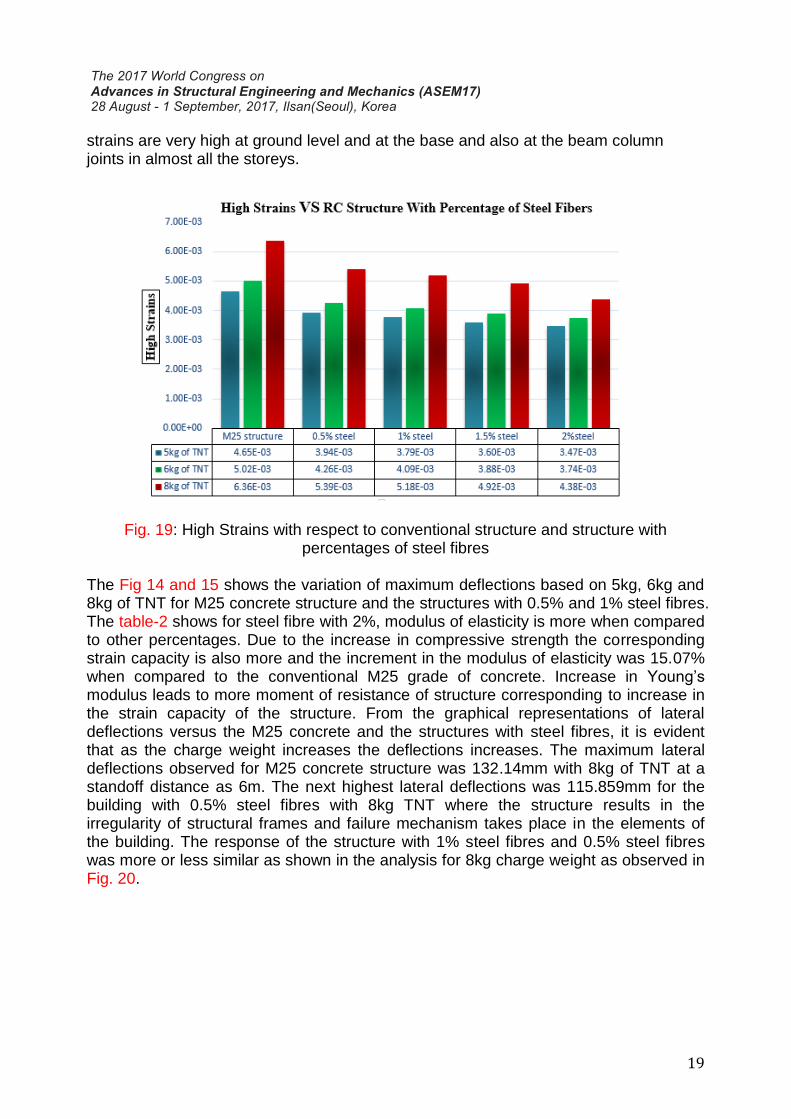
The Fig. 19 and Fig. 20 shows the response of the structures subjected to blast loading and the response involves effect of high strain and lateral deflections. The figures are drawn based on the maximum strains and maximum lateral deflections observed at different levels of structure. The high strains in the structure with 2% steel fibres observed at different levels as illustrated in the Fig. 18. After the blast load analysis for structures with steel fibres and without steel fibres, it was observed that as the percentage of steel fibres increases the ductility of the material as well as the members increases, greater the ductility the structure provides more resistance to failure. The strains observed at the intermediate columns with grids B, C and D, first storey beams which are connected to slabs were also affected. The peak strains for M25 concrete structure was observed as 0.00636 as illustrated in Fig. 19, whereas high strains for structure with 2% steel fibres was observed as 0.004378 for 8kg of TNT which was slightly more than the nominal strain capacity of concrete. For both the structures the strains observed at the same nodal points, the 2% steel fibres shows more moment of resistance against failure.
Fig. 18: Blast Load Analysis for Structure with 2% Steel Fibres
From the graphical representation shown in Fig. 19, with respect to charge weights 5kg, 6kg and 8kg of TNT the response of the structure was more or less similar in case of 0.5% and 1% steel fibres respectively. From the results obtained it is observed that though the category of blasting considered for the research was surface blast, it is the
19
strains are very high at ground level and at the base and also at the beam column joints in almost all the storeys.
Fig. 19: High Strains with respect to conventional structure and structure with
percentages of steel fibres
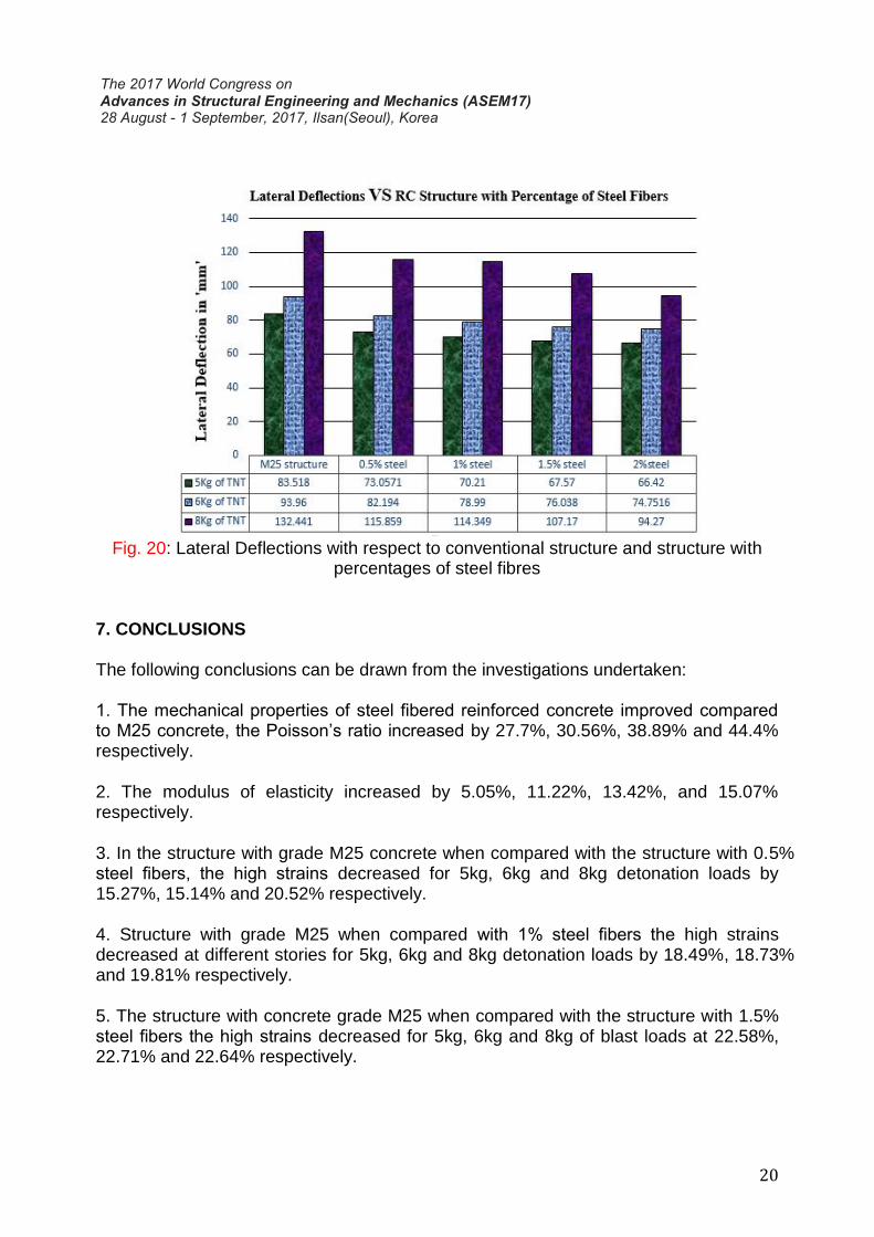
The Fig 14 and 15 shows the variation of maximum deflections based on 5kg, 6kg and 8kg of TNT for M25 concrete structure and the structures with 0.5% and 1% steel fibres. The table-2 shows for steel fibre with 2%, modulus of elasticity is more when compared to other percentages. Due to the increase in compressive strength the corresponding strain capacity is also more and the increment in the modulus of elasticity was 15.07% when compared to the conventional M25 grade of concrete. Increase in Young’s modulus leads to more moment of resistance of structure corresponding to increase in the strain capacity of the structure. From the graphical representations of lateral deflections versus the M25 concrete and the structures with steel fibres, it is evident that as the charge weight increases the deflections increases. The maximum lateral deflections observed for M25 concrete structure was 132.14mm with 8kg of TNT at a standoff distance as 6m. The next highest lateral deflections was 115.859mm for the building with 0.5% steel fibres with 8kg TNT where the structure results in the irregularity of structural frames and failure mechanism takes place in the elements of the building. The response of the structure with 1% steel fibres and 0.5% steel fibres was more or less similar as shown in the analysis for 8kg charge weight as observed in Fig. 20.
20
Fig. 20: Lateral Deflections with respect to conventional structure and structure with percentages of steel fibres
7. CONCLUSIONS The following conclusions can be drawn from the investigations undertaken: 1. The mechanical properties of steel fibered reinforced concrete improved compared to M25 concrete, the Poisson’s ratio increased by 27.7%, 30.56%, 38.89% and 44.4% respectively.
2. The modulus of elasticity increased by 5.05%, 11.22%, 13.42%, and 15.07% respectively.
3. In the structure with grade M25 concrete when compared with the structure with 0.5% steel fibers, the high strains decreased for 5kg, 6kg and 8kg detonation loads by 15.27%, 15.14% and 20.52% respectively.
4. Structure with grade M25 when compared with 1% steel fibers the high strains decreased at different stories for 5kg, 6kg and 8kg detonation loads by 18.49%, 18.73% and 19.81% respectively.
5. The structure with concrete grade M25 when compared with the structure with 1.5% steel fibers the high strains decreased for 5kg, 6kg and 8kg of blast loads at 22.58%, 22.71% and 22.64% respectively.

21
6. When compared to M25 concrete structure and the 2% steel fibers, the high strains decreases for 5kg, 6kg and 8kg of detonation loads at 25.38%, 25.5% and 31.13% respectively.
7. The lateral deflections of the M25 concrete structure without fibers when compared with 0.5% steel fibers decreased by 12.52%, 12.62% and 13.17% respectively.
8. The lateral deflections of the M25 concrete structure without fibres when compared 1% steel fibers decreases by 15.94%, 16.03% and 15.93% respectively.
9. The lateral deflections of the M25 concrete structure without fibers when compared with 1.5% steel fibers decreases by 19.1%, 19.08% and 19.21% respectively.
10. The lateral deflections of the M25 concrete structure without fibers and 2% steel fibers decreases by 20.46%, 20.44% and 38.17% respectively.
From the above investigations, it can be concluded that inclusion of steel fibres in the concrete will help in improving the response of the structure with respect to the strains and the lateral deflections. Further, it can be concluded that for the structures vulnerable to blast loads, the exterior members can be strengthened by including the steel fibers to reduce the effects due to blast pressures and a minimum setback of 6m to be provided all round the building.
REFERENCES
[1] JunLi, Chengqing Wu, and HongHao,”Blast resistance of concrete slab reinforced with high performance fibre material,” Journal of Structural Integrity and Maintenance, vol. 1, no. 2, pp. 51-59,02 june 2016. [2] Xiaoshan Lin and Y. X. Zhang , “Nonlinear Finite Element Analysis of FRPStrengthened Reinforced Concrete Panels Under Blast Loads ,” International JournalofComputationalMethods.,vol.13,no.4,pp.1641002:1-17,08January2016. [3] SalehH. Alsayed and H.M.Elsanadedy,”Blast response of GFRP-strengthened infill masonry walls,” Construction and Building Materials, pp. 438-451, 11 April 2016. [4] Dasari Sudheer Kumar, Pallavi Rai and Rajneesh Kumar “Behaviour of Reinforced Concrete Building Frame Subjected to Different Types of Blast Loading,” Indian Journal of Science and Technology, vol. 9, no. 23, June 2016. [5] Hong Hao, Gang Chen and Yifei Hao,”Experimental tests of steel fibre reinforced concrete beams under drop-weight impacts,” Key Engineering Materials, vol. 626 pp. 311-316, 07 December 2015.

22
[6] J.I. Siddiqui, “Impulsive loading on structures,” Proceedings of Institution of Civil Engineers (Structure and Buildings), pp. 231-241, 2012 [7] Juechun Xu,”Behaviour of Ultra High Performance Concrete Columns Subjected to Blast Loadings Construction and Building Materials, 2015. [8] Damasceno Iana Ingrid Rocha, Maur´ıcio de Pina Ferreira and Dˆenio Ramam Carvalho de Oliveira,”RC beams with steel fibres under impact loads,” Acta Scientiarum. Technology, vol. 36, no. 1 pp. 23-31, March 2014. [9] Mohammed Alias Yusof and Norazman,”Normal Strength Steel Fiber Reinforced Concrete Subjected to Explosive Loading,” International Journal of Sustainable Construction Engineering and Technology, vol. 1, no. 2, December 2010. 80 [10] T. Ngo, P. Mendis, A. Gupta and J. Ramsay,”Blast Loading and Blast Effects on Structures – An Overview,” EJSE Special Issue: Loading on Structures, 2007 [11] Z.XianLia,”Anewmethodforprogressivecollapseanalysis,”ElsevierLtd, no.29, March 2010. [12] Damasceno Iana Ingrid Rocha, Maur´ıcio de Pina Ferreira and Dˆenio Ramam Carvalho de Oliveira,”Design and Analysis of Blast Load on Structures,” International Research Journal of Engineering and Technology (IRJET), vol.02, no.1pp. 745-747, October 2015. [13] Y.S. Tai and T.L. Chu,”Dynamic response of a reinforced concrete slab subjected to air blast load,” Theoretical and Applied Fracture Mechanics, vol. 56, pp. 140147, 15 November 2011. [14] D.O.Dusenberry,”HandBookforBlastResistantDesignOfBuildings”.Canada: John Wiley and Sons, Inc. [15] IS 4991:1968, Indian Standard on Blast Load Resistant Design of Structures for the Blasts above Ground, Bureau of Indian Standards, New Delhi. [16] A.K. Pandey et al., “Non-linear response of reinforced concrete containment structure,” Journal of Nuclear Engineering and design, vol. 236, pp. pp.993-1002., April 2006. [17] J.M. Dewey, “The Properties of Blast Waves Obtained from an analysis of the particle,” A.314, pp. 275-299., Scotland, 1971.