performance of hybrid steel fibers reinforced concrete subjected
TRANSCRIPT
Hindawi Publishing CorporationAdvances in Materials Science and EngineeringVolume 2013, Article ID 420136, 7 pageshttp://dx.doi.org/10.1155/2013/420136
Research ArticlePerformance of Hybrid Steel Fibers Reinforced ConcreteSubjected to Air Blast Loading
Mohammed Alias Yusof,1 Norazman Mohamad Nor,1 Ariffin Ismail,2 Ng Choy Peng,1
Risby Mohd Sohaimi,1 and Muhammad Azani Yahya1
1 Faculty of Engineering, Universiti Pertahanan Nasional Malaysia, Kem Sungai Besi, 57000 Kuala Lumpur, Malaysia2 Faculty of Defence Management and Studies, Universiti Pertahanan Nasional Malaysia, Kem Sungai Besi,57000 Kuala Lumpur, Malaysia
Correspondence should be addressed to Mohammed Alias Yusof; [email protected]
Received 14 May 2013; Revised 11 September 2013; Accepted 16 September 2013
Academic Editor: Gonang Xie
Copyright © 2013 Mohammed Alias Yusof et al.This is an open access article distributed under the Creative Commons AttributionLicense, which permits unrestricted use, distribution, and reproduction in anymedium, provided the originalwork is properly cited.
This paper presents the results of the experimental data and simulation on the performance of hybrid steel fiber reinforced concrete(HSFRC) and also normal reinforced concrete (NRC) subjected to air blast loading. HSFRC concrete mix consists of a combinationof 70% long steel hook end fibre and also 30% of short steel hook end fibre with a volume fraction of 1.5% mix. A total of sixconcrete panels were subjected to air blast using plastic explosive (PE4) weighing 1 kg each at standoff distance of 0.3 meter. Theparameters measured are mode of failure under static and blast loading and also peak overpressure that resulted from detonationusing high speed data acquisition system. In addition to this simulation work using AUTODYNwas carried out and validated usingexperimental data. The experimental results indicate that hybrid steel fiber reinforced concrete panel (HSFRC) possesses excellentresistance to air blast loading as compared to normal reinforced concrete (NRC) panel. The simulation results were also found tobe close with experimental data. Therefore the results have been validated using experimental data.
1. Introduction
Terrorists attack on buildings and infrastructures has becomea global phenomenon. In most cases, the terrorists usedexplosives located in vehicles and blew it up at a close distancefrom the target. Intensive shock waves are created by thisexplosion which propagates outward at supersonic velocityaccompanied by heat and light that induce pressure on thestructural buildings and causes significant damage to thestructure and loss of life. There are a number of methodsto stop the terrorist attack. One of the methods is gatheringinformation on the terrorist and stopping the attack before ittakes place; another way is to protect buildings from damageby incorporating blast resistance design and also retrofittingof the existing structure [1].
This area of research is currently receivingmore attentionfrom many structural engineers as they began to considerblast loading and also blast resistance materials in theirdesign in order to protect important buildings and structures
from such attacks. Concrete is one of the most widely usedconstruction materials for structures because it possessesconsiderable mass per unit cost compared to other construc-tion materials and has excellent fire resistance and is ableto absorb large amounts of energy [2]. However, one of thedisadvantages of concrete is that it has a very low resistanceagainst tensile stress and also possesses low ductility. Fromprevious research it was found that mechanical properties ofthe concrete can be improved by adding fibers into the mix.Otter and Naaman reported that the addition of fibre in theconcrete has significant effect on strength and toughness ofconcrete [3].The test results ofNagarkar andTambe indicatedthat the compressive, split tensile, and flexural strength ofconcrete are increased by the addition of fibre [4].
The strengthening mechanism of fibre involves transferof stress from matrix to the fibre by interlocking the fibersand matrices when the fibre surface is deformed. The stressis thus shared by the fibers and matrix in tension, untilthe matrix cracks and then the total stress is progressively

2 Advances in Materials Science and Engineering
Figure 1: Reinforced concrete test panels.
Figure 2: Field blast test setup.
transferred to the fibers [5]. When steel fibers reinforcedbeam or other structural elements are loaded, steel fibersin the matrix will bridge the cracks. The bridging actionprovides the steel fibre concrete with a higher ultimate tensilestrength, toughness, and also energy absorption capability ascompared with concrete without fibre [6].
Mohammadi et al. stated that the combination of twodifferent fibers which are also known as hybrid fibre in aconcrete mix offers more attractive engineering propertiesrather than single fibre [7]. Bentur and Mindess also foundthat hybrid steel fibers with combination of short and longfibre improved the toughness and ductility of the concrete.This is because short fibers in the concrete mix bridge themicrocracks which lead to a higher tensile strength of thecomposite, while the long fibre arrests the propagaton ofmacrocracks and substantially improves the toughness andductility of the composite [8]. Many researchers have studiedthe mechanical properties of hybrid steel fibre reinforcedconcrete. However, none of the work was done on the per-formance of the hybrid steel fibers reinforced concrete whichis subjected to air blast loading. This research, therefore,plans to investigate the performance of hybrid steel fibersreinforced concrete subjected to air blast loading.
2. Experiments
2.1. Materials and Mix Proportions. In this experiment twotypes of concrete mixes were used which are, normal rein-forced concrete (NRC) and the hybrid steel fibre reinforced
Figure 3: Pressure sensor.
concrete (HSFRC). NRC concrete consists of cement, water,aggregate, and sand, while the HSFRC is made of cement,water, aggregate, sand, and also mixture of two differentlengths of hooked end steel fibers. The lengths of the fiberswere 30mm and 60mm. The steel fibers have a combinationof 70% long + 30% short hooked end steel fibers with thevolume fraction of 1.5%. These fibers have tensile strength of1100MPa.
NRC and HSFRC were mixed using a proportion ofcement : water : aggregate : sand at 358 : 190 : 1167 : 752 kg/m3.In the production of concrete, initially, the aggregate and sandwere added into the mixer and mixed for 2 minutes and thenthe cement and water were poured into the mixer and mixedfor another 5 minutes. At the end of the process, the fiberswere added and mixed for 10 minutes. The fibers were addedin small amounts to avoid fibre balling and to produce theconcrete with good material consistency and workability.
The freshly mixed steel fibre reinforced concrete waspoured in two equal layers of mould to cast a standard150mm × 150mm × 150mm cube and 150mm × 300mmcylinder concrete specimen for a compressive strength testand a split tensile test. For the flexure strength test, a100mm × 100mm × 500 beam mould was used. Each layerwas evenly vibrated for 50 seconds using a vibrating tableand was left in a room temperature for 24 hours and then thespecimen was removed from the mould and cured in waterfor 28 days.
Finally the NRC and HSFRC were poured separately intothe mould of 600mm × 600mm × 150mm to make theminto test panels.These panels were reinforced on both tensionand compression face with 10mm diameter steel at 200mmcentre-to-centre in both ways. The NRC and HSFRC panelswere later removed from the mould after consolidation andcured with wet gunny sacks for 28 days before the actual fieldblast test. A total of six numbers of NRC and HSFRC panelswere fabricated for the blast testing.
2.2. Field Blast Testing Program. A field blast test was con-ducted on the NRC and also HSFRC panels to investigate theperformance of the concrete panels under blast loading. Thefield blast was conducted at an undisclosed military facility.The concrete test panels used for the testing are shown inFigure 1.

Advances in Materials Science and Engineering 3
(a) (b)
Bridging effect of fibres
(c)
Figure 4: (a) Failure mode of NRC. (b) Failure mode of HSFRC. (c) Bridging effect of steel fibers in HSFRC cube.
Table 1: Mechanical properties of NRC and HSFRC.
Average strength (MPa) NRC HSFRCCompressive 31.6 38.2Flexural 4.1 7.7Split tensile 3.0 5.0
The panels were placed on the site at a proper steel frametesting rig like a table which was fabricated at the FabricationLaboratory of the Faculty of Engineering, Universiti Perta-hanan Nasional Malaysia. The size of the blast testing rigin the plan is 700mm, face turned towards the blast. Theheight of the test frame is 1000mm, including a 150mm thickconcrete base. The testing rig provides support along twosides of the specimen. The panel has been set up as a twoway slab design with a span of 600mm. A wooden timbersupporting the explosive was erected to hold the charge. BothNRC and HSFRC concrete panels were tested using 1 kg ofplastic explosive (PE4) at a standoff distance of 300mm.Thefield blast test setup is shown in Figure 2.
In this experiment high speed data acquisition systemwith sampling rate up to 2MHz and eight hardware-timeddigital I/O lines were used tomeasure the structural responsetowards blast loading. The results of the experiment weredisplayed using LabVIEW program. The data acquisitionsystem and instrumentation were located inside a protectedconcrete building approximately 30 meters from the blasttesting site. Pressure sensor was used to capture the blast peakoverpressure. This sensor was fixed at the edge of the testingjig and connected via cable to the data acquisition systemmodule. The pressure sensor is shown in Figure 3.
3. Experimental Results and Discussion
3.1.Mechanical Properties of Hybrid Steel Fibre. Thecompres-sive, flexural, and split tensile strength were conducted on theconcrete specimens to determine the mechanical propertiesof the concretemix.The test results formechanical propertiesof NRC and HSFRC are shown in Table 1.
The result shows that the addition of hybrid steel fibersinto the concrete mix increases the compressive, flexural, andalso tensile strength of the concrete mix.
(a)
(b)
Bridging action of steel fibres
(c)
Figure 5: (a) Failure mode of NRC beam under flexural loading. (b)Failure mode of HSFRC beam under flexural loading. (c) Bridgingaction on steel fibers in the HSFRC beam.
3.2. Failure Mode of Hybrid Steel Fiber Concrete under StaticLoading. The failure mode of the NRC and HSFRC concretecubes under compression is shown in Figures 4(a) and 4(b).
From the results it was observed that the lateral surfacesfor NRC mix cube as shown in Figure 4(a) split from maincore and only the centre of the core remained intact.However,as for the HSFRC cubes, as shown in Figure 4(b), the lateralcore still remained held together with the rest of the cubesurface. This is because of the bridging effect of the steelfibers which interlocks fibers with the coarse aggregate. Thebridging effect of the steel fibers in the HSFRC mix is shownin Figure 4(c).
The failure mode of the NRC and HSFRC beams underflexural loading is shown in Figures 5(a) and 5(b).
It was observed that the NRC beam broke into two partswhen it was subjected to flexural loading. However, whenthe load was put on the HSFRC as shown in Figure 5(b), itwithstood the loading. The inclusion of steel fibers, in the
4 Advances in Materials Science and Engineering
(a) (b)
Bridging effect of fibres
(c)
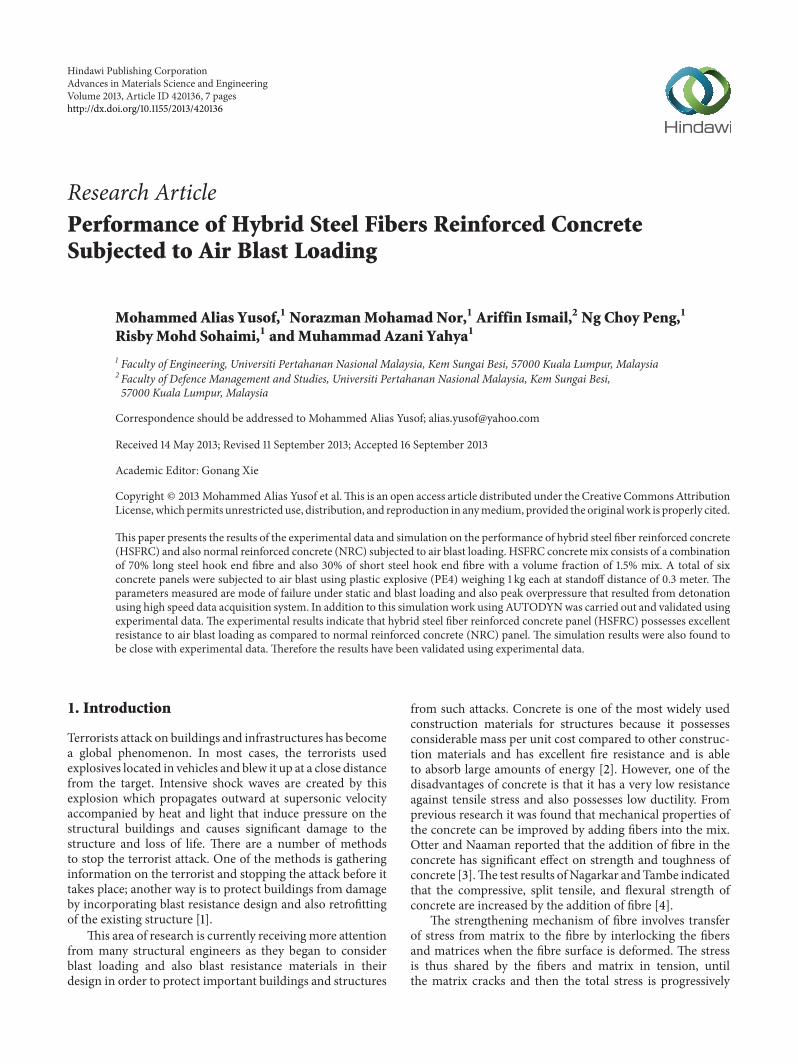
Figure 6: (a) Failure mode of NRC cylinder. (b) Failure mode of HSFRC cylinder. (c) Bridging action of steel fibers in HSFRC cylinder.
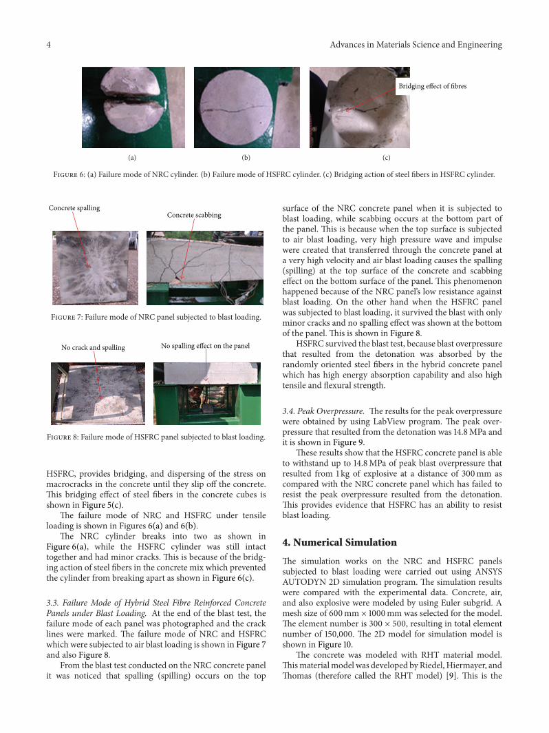
Concrete spalling Concrete scabbing
Figure 7: Failure mode of NRC panel subjected to blast loading.
No crack and spalling No spalling effect on the panel
Figure 8: Failure mode of HSFRC panel subjected to blast loading.
HSFRC, provides bridging, and dispersing of the stress onmacrocracks in the concrete until they slip off the concrete.This bridging effect of steel fibers in the concrete cubes isshown in Figure 5(c).
The failure mode of NRC and HSFRC under tensileloading is shown in Figures 6(a) and 6(b).
The NRC cylinder breaks into two as shown inFigure 6(a), while the HSFRC cylinder was still intacttogether and had minor cracks. This is because of the bridg-ing action of steel fibers in the concrete mix which preventedthe cylinder from breaking apart as shown in Figure 6(c).
3.3. Failure Mode of Hybrid Steel Fibre Reinforced ConcretePanels under Blast Loading. At the end of the blast test, thefailure mode of each panel was photographed and the cracklines were marked. The failure mode of NRC and HSFRCwhich were subjected to air blast loading is shown in Figure 7and also Figure 8.
From the blast test conducted on the NRC concrete panelit was noticed that spalling (spilling) occurs on the top
surface of the NRC concrete panel when it is subjected toblast loading, while scabbing occurs at the bottom part ofthe panel. This is because when the top surface is subjectedto air blast loading, very high pressure wave and impulsewere created that transferred through the concrete panel ata very high velocity and air blast loading causes the spalling(spilling) at the top surface of the concrete and scabbingeffect on the bottom surface of the panel. This phenomenonhappened because of the NRC panel’s low resistance againstblast loading. On the other hand when the HSFRC panelwas subjected to blast loading, it survived the blast with onlyminor cracks and no spalling effect was shown at the bottomof the panel. This is shown in Figure 8.
HSFRC survived the blast test, because blast overpressurethat resulted from the detonation was absorbed by therandomly oriented steel fibers in the hybrid concrete panelwhich has high energy absorption capability and also hightensile and flexural strength.
3.4. Peak Overpressure. The results for the peak overpressurewere obtained by using LabView program. The peak over-pressure that resulted from the detonation was 14.8MPa andit is shown in Figure 9.
These results show that the HSFRC concrete panel is ableto withstand up to 14.8MPa of peak blast overpressure thatresulted from 1 kg of explosive at a distance of 300mm ascompared with the NRC concrete panel which has failed toresist the peak overpressure resulted from the detonation.This provides evidence that HSFRC has an ability to resistblast loading.
4. Numerical Simulation
The simulation works on the NRC and HSFRC panelssubjected to blast loading were carried out using ANSYSAUTODYN 2D simulation program. The simulation resultswere compared with the experimental data. Concrete, air,and also explosive were modeled by using Euler subgrid. Amesh size of 600mm × 1000mm was selected for the model.The element number is 300 × 500, resulting in total elementnumber of 150,000. The 2D model for simulation model isshown in Figure 10.
The concrete was modeled with RHT material model.Thismaterialmodel was developed by Riedel, Hiermayer, andThomas (therefore called the RHT model) [9]. This is the

Advances in Materials Science and Engineering 5
16
14
12
10
8
6
4
2
00.05 0.10 0.15 0.20
Pres
sure
(MPa
)
Time (s)
Figure 9: Peak overpressure resulted from 1 kg of plastic explosiveat a distance of 300mm.
Explosive
Reinforcedconcrete panel
Air
Steelreinforcement
Figure 10: 2D model for simulation works.
standard material model for concrete in the material libraryof AUTODYN that describes the behavior of concrete.
Johnson Cook material model was used to describe thebehavior of the steel reinforcement inside the concrete [10].This is the standard material model for steel reinforcementin the material library of AUTODYN that describes thebehavior of steel reinforcement, subjected to explosion. Theyield strength for both control mix concrete and also hybridsteel fiber concrete steel bar reinforcement was taken as460MPa based on the high strength steel bar materialsstrength properties obtained from BS 8110: Part 1: 1997 [11].
Air was modeled as an ideal gas. The air density used is𝜌 = 1.225 kg/m3 and air initial internal energy used is 2.068×10⁵ kJ/kgwhich is obtained fromAUTODYNmaterial library.Jones-Wilkins-Lee (JWL) equation of state was used tomodelthe rapid expansion of high explosive detonation of plasticexplosive [12]. The material properties of plastic explosive(PE4) were obtained from AUTODYNmaterial library.
Major deformation at the support and middle span of the concrete panel
Steel reinforcement deformed
(a)
Major cracks at the support and middle span of the panels
(b)
Figure 11: (a) Simulation results for NRC panel. (b) Experimentresults for NRC panel.
5. Simulation Results and Discussion
5.1. Simulation Results for NRC Panel. The comparison ofcrack areas that are obtained from simulations with thosewith experimental test results for NRC panel is shown inFigures 11(a) and 11(b). In the simulation works the cracklocation on the concrete panels can be identified through thedeformation pattern on the concrete panels.
From the simulation results as shown in Figure 11(a) itwas shown that there is major deformation on the NRC panelat the support and also midspan of the concrete panel. Inaddition to this, the steel reinforcement also has deformed orwas bent at the centre of the panel. This indicates that thereis high possibility of cracks occurring at the deformation areawhen concrete is deformed. Further to this, the location ofthe deformed or cracked area is found to be at the samelocation as seen in the experimental results which are shownin Figure 11(b). Therefore the simulation results agreed wellwith the experimental work.
5.2. Simulation Results for HSFRC Panel. The simulation andalso experimental results for HSFRC panel are shown inFigures 12(a) and 12(b).
From the simulation results as shown, there is a minordeformation near the midspan of the concrete panel. Thisindicates a high possibility of minor cracks occurring at thedeformed areawhen concrete is deformed.The location of thedeformedor cracked areawas found to be at the same locationas seen in the experimental results. Therefore the simulationresults agreed well with the experimental work.
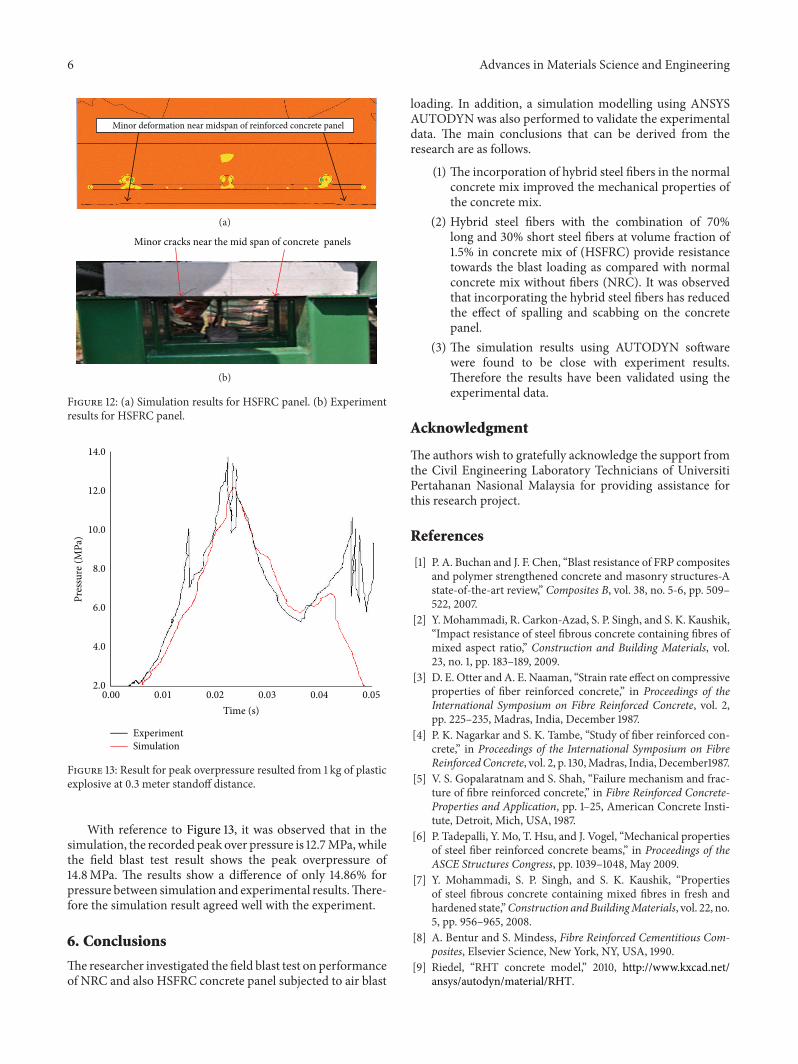
5.3. Peak Overpressure Results. The simulation and experi-mental results for the peak overpressure at 0.3 meter from thepoint of blast are shown in Figure 13.
6 Advances in Materials Science and Engineering
Minor deformation near midspan of reinforced concrete panel
(a)
Minor cracks near the mid span of concrete panels
(b)
Figure 12: (a) Simulation results for HSFRC panel. (b) Experimentresults for HSFRC panel.
Time (s)
ExperimentSimulation
Pres
sure
(MPa
)
14.0
12.0
10.0
8.0
6.0
4.0
2.00.00 0.01 0.02 0.03 0.04 0.05
Figure 13: Result for peak overpressure resulted from 1 kg of plasticexplosive at 0.3 meter standoff distance.
With reference to Figure 13, it was observed that in thesimulation, the recorded peak over pressure is 12.7MPa,whilethe field blast test result shows the peak overpressure of14.8MPa. The results show a difference of only 14.86% forpressure between simulation and experimental results.There-fore the simulation result agreed well with the experiment.
6. Conclusions
Theresearcher investigated the field blast test on performanceof NRC and also HSFRC concrete panel subjected to air blast
loading. In addition, a simulation modelling using ANSYSAUTODYN was also performed to validate the experimentaldata. The main conclusions that can be derived from theresearch are as follows.
(1) The incorporation of hybrid steel fibers in the normalconcrete mix improved the mechanical properties ofthe concrete mix.
(2) Hybrid steel fibers with the combination of 70%long and 30% short steel fibers at volume fraction of1.5% in concrete mix of (HSFRC) provide resistancetowards the blast loading as compared with normalconcrete mix without fibers (NRC). It was observedthat incorporating the hybrid steel fibers has reducedthe effect of spalling and scabbing on the concretepanel.
(3) The simulation results using AUTODYN softwarewere found to be close with experiment results.Therefore the results have been validated using theexperimental data.
Acknowledgment
The authors wish to gratefully acknowledge the support fromthe Civil Engineering Laboratory Technicians of UniversitiPertahanan Nasional Malaysia for providing assistance forthis research project.
References
[1] P. A. Buchan and J. F. Chen, “Blast resistance of FRP compositesand polymer strengthened concrete and masonry structures-Astate-of-the-art review,” Composites B, vol. 38, no. 5-6, pp. 509–522, 2007.
[2] Y. Mohammadi, R. Carkon-Azad, S. P. Singh, and S. K. Kaushik,“Impact resistance of steel fibrous concrete containing fibres ofmixed aspect ratio,” Construction and Building Materials, vol.23, no. 1, pp. 183–189, 2009.
[3] D. E. Otter andA. E. Naaman, “Strain rate effect on compressiveproperties of fiber reinforced concrete,” in Proceedings of theInternational Symposium on Fibre Reinforced Concrete, vol. 2,pp. 225–235, Madras, India, December 1987.
[4] P. K. Nagarkar and S. K. Tambe, “Study of fiber reinforced con-crete,” in Proceedings of the International Symposium on FibreReinforcedConcrete, vol. 2, p. 130,Madras, India, December1987.
[5] V. S. Gopalaratnam and S. Shah, “Failure mechanism and frac-ture of fibre reinforced concrete,” in Fibre Reinforced Concrete-Properties and Application, pp. 1–25, American Concrete Insti-tute, Detroit, Mich, USA, 1987.
[6] P. Tadepalli, Y. Mo, T. Hsu, and J. Vogel, “Mechanical propertiesof steel fiber reinforced concrete beams,” in Proceedings of theASCE Structures Congress, pp. 1039–1048, May 2009.
[7] Y. Mohammadi, S. P. Singh, and S. K. Kaushik, “Propertiesof steel fibrous concrete containing mixed fibres in fresh andhardened state,”Construction andBuildingMaterials, vol. 22, no.5, pp. 956–965, 2008.
[8] A. Bentur and S. Mindess, Fibre Reinforced Cementitious Com-posites, Elsevier Science, New York, NY, USA, 1990.
[9] Riedel, “RHT concrete model,” 2010, http://www.kxcad.net/ansys/autodyn/material/RHT.

Advances in Materials Science and Engineering 7
[10] U.Nystrom andK.Gylltoft, “Numerical studies of the combinedeffects of blast and fragment loading,” International Journal ofImpact Engineering, vol. 36, no. 8, pp. 995–1005, 2009.
[11] British Standard Institution, BS, 8110: Part 1: Code of Practice forDesign and Construction, British Standard Institution, London,UK, 1997.
[12] U. Nystrom, Numerical simulation of fiber reinforced concretesubjected to blast impact [M.S. thesis], Chalmer University ofTechnology, Goteborg, Sweden, 2008.

Submit your manuscripts athttp://www.hindawi.com
ScientificaHindawi Publishing Corporationhttp://www.hindawi.com Volume 2014
CorrosionInternational Journal of
Hindawi Publishing Corporationhttp://www.hindawi.com Volume 2014
Polymer ScienceInternational Journal of
Hindawi Publishing Corporationhttp://www.hindawi.com Volume 2014
Hindawi Publishing Corporationhttp://www.hindawi.com Volume 2014
CeramicsJournal of
Hindawi Publishing Corporationhttp://www.hindawi.com Volume 2014
CompositesJournal of
NanoparticlesJournal of
Hindawi Publishing Corporationhttp://www.hindawi.com Volume 2014
Hindawi Publishing Corporationhttp://www.hindawi.com Volume 2014
International Journal of
Biomaterials
Hindawi Publishing Corporationhttp://www.hindawi.com Volume 2014
NanoscienceJournal of
TextilesHindawi Publishing Corporation http://www.hindawi.com Volume 2014
Journal of
NanotechnologyHindawi Publishing Corporationhttp://www.hindawi.com Volume 2014
Journal of
CrystallographyJournal of
Hindawi Publishing Corporationhttp://www.hindawi.com Volume 2014
The Scientific World JournalHindawi Publishing Corporation http://www.hindawi.com Volume 2014
Hindawi Publishing Corporationhttp://www.hindawi.com Volume 2014
CoatingsJournal of
Advances in
Materials Science and EngineeringHindawi Publishing Corporationhttp://www.hindawi.com Volume 2014
Smart Materials Research
Hindawi Publishing Corporationhttp://www.hindawi.com Volume 2014
Hindawi Publishing Corporationhttp://www.hindawi.com Volume 2014
MetallurgyJournal of
Hindawi Publishing Corporationhttp://www.hindawi.com Volume 2014
BioMed Research International
MaterialsJournal of
Hindawi Publishing Corporationhttp://www.hindawi.com Volume 2014
Nano
materials
Hindawi Publishing Corporationhttp://www.hindawi.com Volume 2014
Journal ofNanomaterials