analysis of automobile radiator using ... - … journal of latest technology in engineering,...
TRANSCRIPT

International Journal of Latest Technology in Engineering, Management & Applied Science (IJLTEMAS)
Volume V, Issue VI, June 2016 | ISSN 2278-2540
www.ijltemas.in Page 156
Analysis of Automobile Radiator Using
Computational Fluid Dynamics
Rinu Sathyan
Assistant Professor in Mechanical Engineering, SCT College of Engineering,Trivandrum, Kerala, India
Abstract- Radiators are a type of heat exchangers used to
transfer thermal energy from one medium to another for the
purpose of cooling and heating. Upwards of 33% of energy
generated by the engine through combustion is lost in heat.
Insufficient heat dissipation can result in the overheating of
engine, which leads to the breakdown of the lubricating oil, metal
weakening of engine parts, and significant wear between engine
parts. To minimize the stress on the engine as a result of heat
generation, automotive radiators must be redesigned to be more
compact while still maintaining high level of heat transfer
components. This lead to the increased demand on the power
packed radiators, which can dissipate maximum amount of heat
for any given space. This project aims to do a comparison
between ordinary straight tube radiator and a new helical tube
radiator. The modelling is done using SolidWorks. The fluid flow
analysis is done with Ansys Fluent
I. INTRODUCTION
ost modern cars use aluminium radiators. These
radiators are made by brazing thin aluminium fins to
flattened aluminum tubes. The coolant flows from the inlet to
the outlet through many tubes mounted in a parallel
arrangement. The fins conduct the heat from the tubes and
transfer it to the air flowing through the radiator.
The tubes sometimes have a type of fin inserted into
them called a tabulator, which increases the turbulence of the
fluid flowing through the tubes. If the fluid flowed very
smoothly through the tubes, only the fluid actually touching
the tubes would be cooled directly. The amount of heat
transferred to the tubes from the fluid running through them
depends on the difference in temperature between the tube and
the fluid touching it. So if the fluid that is in contact with the
tube cools down quickly, less heat will be transferred. By
creating turbulence inside the tube, all of the fluid mixes
together, keeping the temperature of the fluid touching the
tubes up so that more heat can be extracted, and all of the fluid
inside the tube is used effectively. Radiators usually have a
tank on each side, and inside the tank is a transmission cooler.
In the picture above, you can see the inlet and outlet where the
oil from the transmission enters the cooler. The transmission
cooler is like a radiator within a radiator, except instead of
exchanging heat with the air, the oil exchanges heat with the
coolant in the radiator.
This projects deals with the comparison of a normal
straight tube radiator with modified one. Radiator of TATA
INDIGO/INDICA is taken as a standard model and its tubes
are replaced with helical tubes. Analysis of the radiator is done
through CFD (Computational Fluid Dynamics) using ANSYS
Fluent software. The temperature distribution and the fluid
flow inside the radiator is analyzed and various plots are
plotted.
II. METHODOLOGY
Generic Steps To Solving Problem in Fluent:
Like solving any problem analytically, you need to define (1)
your solution domain, (2) the physical model, (3) boundary
conditions and (4) the physical properties. You then solve the
problem and present the results. In numerical methods, the
main difference is an extra step called mesh generation. This is
the step that divides the complex model into small elements
that become solvable in an otherwise too complex situation.
Below describes the processes in terminology slightly more
attune to the software.
Build Geometry
Construct a two or three dimensional representation of the
object to be modeled and tested using the work plane
coordinates system within ANSYS.
Define Material Properties
Now that the part exists, define a library of the necessary
materials that compose the object (or project) being modeled.
This includes thermal and mechanical properties.
Generate Mesh
At this point ANSYS understands the makeup of the part.
Now define how the Modeled system should be broken down
into finite pieces.
Define Boundary Conditions
Once the system is fully designed, the last task is to burden the
system with constraints, such as physical loadings or boundary
conditions.
M

International Journal of Latest Technology in Engineering, Management & Applied Science (IJLTEMAS)
Volume V, Issue VI, June 2016 | ISSN 2278-2540
www.ijltemas.in Page 157
Obtain Solution
This is actually a step, because ANSYS needs to understand
within what state (steady state, transient… etc.) the problem
must be solved
Present the Results
After the solution has been obtained, there are many ways to
present ANSYS‟ results, choose from many options such as
tables, graphs, and contour plots.
III. SPECIFICATIONS OF THE RADIATOR:
TABLE 1
SPECIFICATION
Details Dimensions (mm)
Length 644
Width 30
Height 360
Tube length 584
Tube inner diameter 7
Tube outer diameter 9
Tube Material: Aluminum
Coolant Fluid: A Mixture Of Ethylene Glycol (25%) &
Water (75%)
IV. BOUNDARY CONDITIONS
The main boundary condition include, a mass flow
rate inlet boundary condition where used in the inlet nozzles.
The cylindrical shaped geometries are the wall. At the outlet,
the pressure outlet (atmospheric pressure) boundary condition
was used. And all other portions are considered as the wall
boundary with convective heat transfer surfaces.
INLET
Select inlet and change type to mass flow inlet
Enter the mass-flow rate
Enter the value of inlet gauge pressure = 1.5e5 Pa
Provide the inlet temperature = 368K
Change the option under Direction Specification to
“Normal to boundary”
OUTLET
Select the outlet and change type to „Pressure-outlet‟
Enter the value for outlet gauge pressure = 0 Pa
Change the option under Direction Specification to
“Normal to boundary”
WALL
Select wall and change type to „Wall‟
Select the material for the wall:
Aluminium
Choose convection as the heat transfer mechanism
employed in wall.
Enter the value for heat transfer coefficient as 90
W/m²K.
Enter wall thickness as 1mm
Enter the free stream temperature on wall
V. CONTOUR PLOTS
At first the analysis is done by keeping inlet temperature
of coolant and free stream temperature constant and
temperatures are obtained for different mass flow rates. Varied
input mass flow rates are given in the table.
Temperature Contour
1. Mass flow rate 500kg/h
Fig. 1. Temperature contour for mass flow rate 500kg/h
2. Mass flow rate 1000kg/h
Fig. 2. Temperature contour for mass flow rate 1000kg/h

International Journal of Latest Technology in Engineering, Management & Applied Science (IJLTEMAS)
Volume V, Issue VI, June 2016 | ISSN 2278-2540
www.ijltemas.in Page 158
Fig. 3. Temperature contour for mass flow rate 1500kg/h
Fig.4. Temperature contour for mass flow rate 2000kg/h
Fig.5.. Temperature contour for mass flow rate 2500kg/h
The temperature of coolant at inlet and outlet corresponding to
various mass flow rates obtained during analysis are tabulated
below
TABLE 2 VARIOUS MASS FLOW RATES
Mass flow rates in
Kg/hr
Mass flow rates in
Kg/s
Radiator inlet temperature
(K)
Radiator outlet temperature
(K)
500 0.138 368 340.45
1000 0.277 368 354.45
1500 0.416 368 358.39
2000 0.555 368 359.9
2500 0.694 368 361.07
Analysis by changing free stream air temperature
The second analysis was done by changing free stream
temperature (that is temperature of cooling air) for about five
values which is listed below.
TABLE 3
VALUES OF INPUT FREE STREAM TEMPERATURE
The temperatures of coolant at inlet and outlet corresponding
to various free stream air temperatures obtained during
analysis are given below
TABLE 4
TEMPERATURE OF COOLANT AT INLET AND OUTLET
CORRESPONDING TO VARIOUS MASS FLOW RATES
New design with standard dimensions
The radiator model was redesigned. The straight
tubes were replaced with helical tubes. The length, width and
height were kept constant. The boundary conditions were kept
the same. As the tubes were replaced with helical its overall
length increases.
Air inlet temperature
ᴼ C
Air inlet temperature
K
0 273
10 283
20 293
30 303
40 313
Air inlet temperature
K
Coolant inlet
temperature
K
Coolant outlet
temperature
K
273 368 329.57
283 368 333.62
293 368 337.68
303 368 341.73
313 368 345.8

International Journal of Latest Technology in Engineering, Management & Applied Science (IJLTEMAS)
Volume V, Issue VI, June 2016 | ISSN 2278-2540
www.ijltemas.in Page 159
Fig.6. Helical tube Radiator
TABLE 5
DIMENSIONS OF NEWLY DESIGNED RADIATOR
Details Dimensions (mm)
Length 644
Width 30
Height 360
Tube length 2813.16
Tube inner diameter 7
Tube outer diameter 9
No. of tubes 10
Diameter of helix 30
Pitch of helix 20
Number of turns of helix 26
While analyzing the results we obtained, the following things
were observed
The temperature at the outlet is found to be 356ᴼC.
The temperature drop of fluid in the tubes is due to
the increase in surface area. The increase in surface
area results in increase in heat transfer thus resulting
in better cooling effect.
TABLE 6
COMPARISON OF STRAIGHT TUBE AND HELICALTUBE RADIATOR
Radiator
models
Mass
flow
rate
(Kg/s)
Coolant
inlet
temperature
(K)
Coolant
outlet
temperature
(K)
Overall
heat transfer
coefficient
(W/m2
K)
Effectiveness
%
For
straight
tube
radiator
0.555 368 359.9 882.20 33
For
helical
tube radiator
0.555 368 356 820.05 46
VI. RESULT AND DISCUSSION
• From the two readings it is found that temperature
drop is 4ᴼ higher for helical tube model than a
straight tube model
• Hence heat transfer rate is higher for a helical tube
model
• Its effectiveness gets increased to 13% more than
straight tube model
Our objective is to design a helical radiator which is
suited for TATA INDICA with same efficiency of its
original radiator but with reduced size. For this reverse
engineering has been done. It is found that overall heat
transfer coefficient ranges in same value. We assumed the
overall heat transfer coefficient of helical tube radiator as
820 W/m2K. The inlet and outlet conditions are given
same as that of straight tube radiator. That is
• Air inlet temperature= 308K
• Air outlet temperature= 333K
• Inlet temperature of coolant= 368K
From the listed details total surface area of helical tubes
are found. Then overall length of tubes is found out. For
obtaining new design first we assumed that there are 9
rows of tubes. Then the overall length is divided into nine
parts which gives length of a single tube. This dimension
is divided with length of a single helix to obtain number
of turns. And thus we obtained a new radiator with
reduced dimensions.
For the new dimension the percentage reduction in length
is about 31.6% & height of about 8%. This result shows
that the newly designed radiator is compact and consumes
only less space.
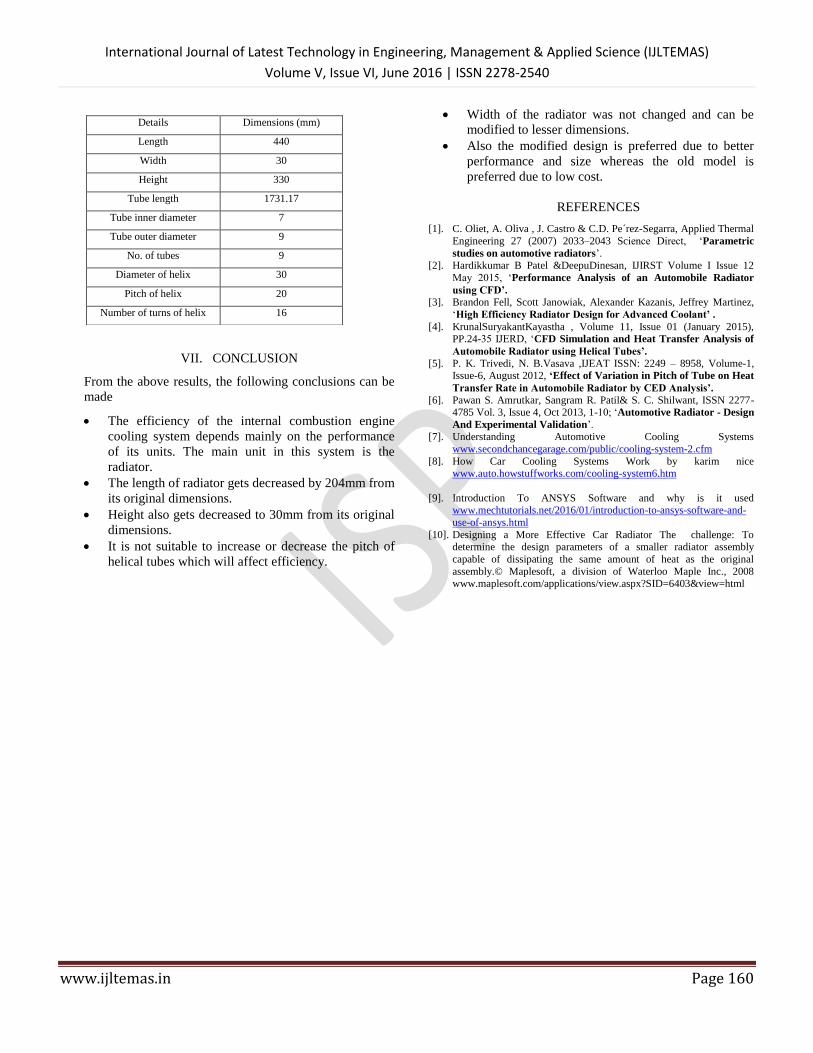
New design with reduced dimensions
Fig.7. Sketch of newly designed Radiator
TABLE 7
DIMENSIONS OF NEWLY DESIGNED RADIATOR
International Journal of Latest Technology in Engineering, Management & Applied Science (IJLTEMAS)
Volume V, Issue VI, June 2016 | ISSN 2278-2540
www.ijltemas.in Page 160
VII. CONCLUSION
From the above results, the following conclusions can be
made
The efficiency of the internal combustion engine
cooling system depends mainly on the performance
of its units. The main unit in this system is the
radiator.
The length of radiator gets decreased by 204mm from
its original dimensions.
Height also gets decreased to 30mm from its original
dimensions.
It is not suitable to increase or decrease the pitch of
helical tubes which will affect efficiency.
Width of the radiator was not changed and can be
modified to lesser dimensions.
Also the modified design is preferred due to better
performance and size whereas the old model is
preferred due to low cost.
REFERENCES
[1]. C. Oliet, A. Oliva , J. Castro & C.D. Pe´rez-Segarra, Applied Thermal
Engineering 27 (2007) 2033–2043 Science Direct, „Parametric
studies on automotive radiators‟. [2]. Hardikkumar B Patel &DeepuDinesan, IJIRST Volume I Issue 12
May 2015, „Performance Analysis of an Automobile Radiator
using CFD’. [3]. Brandon Fell, Scott Janowiak, Alexander Kazanis, Jeffrey Martinez,
„High Efficiency Radiator Design for Advanced Coolant’ .
[4]. KrunalSuryakantKayastha , Volume 11, Issue 01 (January 2015), PP.24-35 IJERD, „CFD Simulation and Heat Transfer Analysis of
Automobile Radiator using Helical Tubes’. [5]. P. K. Trivedi, N. B.Vasava ,IJEAT ISSN: 2249 – 8958, Volume-1,
Issue-6, August 2012, ‘Effect of Variation in Pitch of Tube on Heat
Transfer Rate in Automobile Radiator by CED Analysis’.
[6]. Pawan S. Amrutkar, Sangram R. Patil& S. C. Shilwant, ISSN 2277-4785 Vol. 3, Issue 4, Oct 2013, 1-10; „Automotive Radiator - Design
And Experimental Validation‟. [7]. Understanding Automotive Cooling Systems
www.secondchancegarage.com/public/cooling-system-2.cfm
[8]. How Car Cooling Systems Work by karim nice www.auto.howstuffworks.com/cooling-system6.htm
[9]. Introduction To ANSYS Software and why is it used www.mechtutorials.net/2016/01/introduction-to-ansys-software-and-
use-of-ansys.html
[10]. Designing a More Effective Car Radiator The challenge: To determine the design parameters of a smaller radiator assembly
capable of dissipating the same amount of heat as the original
assembly.© Maplesoft, a division of Waterloo Maple Inc., 2008 www.maplesoft.com/applications/view.aspx?SID=6403&view=html
Details Dimensions (mm)
Length 440
Width 30
Height 330
Tube length 1731.17
Tube inner diameter 7
Tube outer diameter 9
No. of tubes 9
Diameter of helix 30
Pitch of helix 20
Number of turns of helix 16