analysis and assessment of potential scenarios
TRANSCRIPT

RELIABLE APPLICATION SPECIFIC DETECTION OF ROAD USERS WITH VEHICLE ON-BOARD SENSORS
Public Page 1 of 44
DOCUMENT DELIVERABLE NUMBER D1.1 DUE DATE 30/06/2008 ISSUED BY ARC ACTUAL DATE 07.10.2008 CONTRIBUTING WP/TASK WP1 / TASK 1.1 PAGES 9 CONFIDENTIALITY STATUS PUBLIC ANNEXES - PROJECT GRANT AGREEMENT NO. 216049 ACRONYM ADOSE
TITLE RELIABLE APPLICATION SPECIFIC DETECTION OF ROAD USERS WITH VEHICLE ON-BOARD SENSORS
CALL FP7-ICT-2007-1 FUNDING SCHEME STREP
DELIVERABLE D1.1 ANALYSIS AND ASSESSMENT OF POTENTIAL SCENARIOS
AUTHORS
ARC E. SCHOITSCH
APPROVAL WORKPACKAGE LEADER ARC E. SCHOITSCH PROJECT COORDINATOR CRF N. PALLARO
AUTHORISATION
PROJECT OFFICER EUROPEAN COMMISSION I. HEIBER

Public Page 2 of 44
DELIVERABLE D1.1 ANALYSIS AND ASSESSMENT OF POTENTIAL SCENARIOS
Ver. 1.8d Date 07.10.2008 Page 2 of 44
REVISION HISTORY
VER. DATE PAG. NOTES AUTHOR
0.1w 2008-03-04 All Initial version E. Schoitsch
0.5w 2008-04-23 All V0.5 for first review: Input ARC, Bosch, MMSE E. Schoitsch, M.
Gianluca, U. Beutnagel-Buchner
0.6w 2008-05-05 10 Slightly modified scenario 2.2, Input ST E. Schoitsch, L.
Bizzarri
0.6w 2008-05-25 All Update ARC (side impact) E. Schoitsch, W.
Kubinger, M. Litzenberger
0.8w 2008-06-16 All Integration VTT, Update Bosch, ARC, ST V. Ville, H. Hagstedt, E. Schoitsch
1.0d 2008-06-25 All Updates Specs ARC (SRS), Bosch (Review) M. Litzenberger, W. Kubinger, H. Hagstedt
1.1d 2008-07-31 All Update CRF: scenario 2.1, potential and
restrictions of MFOS and 3DCAM, review of the whole document
N. Pallaro
1.2d 2008-08-01 All Update CRF 2 (further review) N. Pallaro
1.3d 2008-08-05 All
Update ARC completed SRS restrictions, scenario side impact,
workflow and related project’s scenarios
E. Schoitsch, M. Litzenberger
1.4d 2008-08-21 All Adapted to new template W. Kubinger
1.45d 2008-08-21 All Minor corrections and re-formatting, conclusions added (VTT, ARC)
V. Ville, E. Schoitsch
1.5d 2008-08-23 All Minor corrections, formatting by ARC integrated E. Schoitsch
1.6d 2008-09-09 All New sections: description of workflow of WP1, state-of-the-art, bibliography.
Final review of the whole document.
N. Pallaro
1.7d 2008-09-15 All Update chapter 4.1, state-of.the-art and bibliography
E. Schoitsch, W. Kubinger
1.8d 2008-10-07 All Final review N. Pallaro

Public Page 3 of 44
DELIVERABLE D1.1 ANALYSIS AND ASSESSMENT OF POTENTIAL SCENARIOS
Ver. 1.8d Date 07.10.2008 Page 3 of 44
TABLE OF CONTENTS
1. INTRODUCTION................................................................................................................................................ 4 1.1 PURPOSE AND SCOPE ................................................................................................................................. 4 1.2 WORKFLOW OF WORKPACKAGE 1 .............................................................................................................. 4
2. ADOSE VISION ................................................................................................................................................. 6 2.1 ADOSE IN CONTEXT OF EUROPEAN ROAD-SAFETY PROJECTS ................................................................ 6 2.2 NOVEL ADOSE SENSORS .......................................................................................................................... 8 2.3 POTENTIAL SCENARIOS FOR ADOSE SENSORS ........................................................................................ 9
3. STATE OF THE ART ........................................................................................................................................ 9 3.1 NIGHT VISION SYSTEMS .............................................................................................................................. 9 3.2 PRE-CRASH SAFETY SYSTEMS.................................................................................................................... 9
4. STUDY ON SCENARIOS AND SELECTION FOR ADOSE....................................................................... 9 4.1 SCENARIOS ADDRESSED IN OTHER REFERENCE PROJECTS ...................................................................... 9 4.2 SELECTED SCENARIOS IN ADOSE............................................................................................................. 9 4.3 CLASSIFICATION OF SCENARIOS ................................................................................................................. 9
5. SCENARIO GROUP DESCRIPTIONS........................................................................................................... 9 5.1 SCENARIOS GROUP 1: COLLISION AVOIDANCE ......................................................................................... 9
5.1.1 Scenario 1.1: Collision Avoidance in Extra-Urban Areas including VRUs .................................. 9 5.1.2 Scenario 1.2: Collision Avoidance in Urban Areas including VRUs............................................. 9
5.2 SCENARIOS GROUP 2: PRE-CRASH WARNING/PREPARATORY ACTIONS ................................................. 9 5.2.1 Scenario 2.1: Pre-Crash Warning/Preparation Front Impact ........................................................ 9 5.2.2 Scenario 2.2: Pre-Crash Warning/Preparatory Actions Side Impact ........................................... 9 5.2.3 Scenario 2.3: Pre-Crash Warning/Preparatory Actions Rear Impact........................................... 9
6. SCENARIO/SENSOR TECHNOLOGY MATRIX.......................................................................................... 9
7. CONCLUSIONS................................................................................................................................................. 9
8. BIBLIOGRAPHY................................................................................................................................................ 9
9. LIST OF FIGURES ............................................................................................................................................ 9
10. LIST OF TABLES ......................................................................................................................................... 9
11. LIST OF ACRONYMS.................................................................................................................................. 9
Public Page 4 of 44
DELIVERABLE D1.1 ANALYSIS AND ASSESSMENT OF POTENTIAL SCENARIOS
Ver. 1.8d Date 07.10.2008 Page 4 of 44
1. INTRODUCTION
1.1 Purpose and scope
Deliverable D1.1 describes the activities carried out in Task 1.1 and the obtained results. Task 1.1 analyses and selects traffic scenarios to be handled by systems based on sensor technologies (new or improved sensors) taken under consideration in ADOSE. Basis is the outcome from past and current research projects and data from roadmaps on road safety.
This document is the basis for the definition of sensor requirements and specifications, included in deliverable D1.2.
1.2 Workflow of workpackage 1
The main objectives of workpackage 1 were as follows:
Analysis and selection of scenarios to be addressed in ADOSE Definition of sensor requirements and specifications for the selected scenarios
The workflow of WP1 is shown in Fig. 1. The starting point of the workpackage was the ADOSE vision, as explained in Annex 1, which can be summarised in the following points:
1. Application context and needs related to the basic functional, performance and cost limits of current safety functions and systems
2. Above mentioned needs as seen with respect to the state of the art of ADAS sensors (from the point of view of the sensing technologies)
3. Proposed novel sensors to be developed in ADOSE 4. Graphical representation of potential scenarios for ADOSE sensors
ADOSE project addresses five breakthrough sensing technologies, with the goal to improve the current state-of-the-art in terms of costs, performance and reliability. It is a technology-oriented project aiming at developing the sensing element and the sensor hardware as complementary project to PReVENT which is mainly focused on the sensor processing and post-processing software. The selection of scenarios to be addressed in ADOSE has to be done taking into account the following criteria:
1. ADOSE is not an application-oriented project which means that novel safety functions have not to be developed and scenarios are already known and to be selected from the past or current projects (R&D, engineering, industrialisation) on active and preventive safety.
2. ADOSE aims at enhancing the current ADAS sensors by breakthrough technological developments; the distinctiveness of each sensor limits the number of scenarios.
3. ADOSE is a product driven project which means that partners have to necessarily select scenarios (preventive and active functions), characterised by higher user demand and acceptance, in order to be competitive on the market.

Public Page 5 of 44
DELIVERABLE D1.1 ANALYSIS AND ASSESSMENT OF POTENTIAL SCENARIOS
Ver. 1.8d Date 07.10.2008 Page 5 of 44
ADOSEVision
Ego-vehicle bound scenarios (D1.1)2 groups: crash-avoidance, pre-crash warning/preparation
3 vehicle positions: front, side, rear impact2 driving environments: extra-urban, urban
Relationship to ADOSE sensor types (D1.1)(potential and restrictions of sensors)
Sensor requirements (D1.2)(depending on the selected scenarios)
Sensor specifications (D1.2)(functional, …)
Use Cases (D7.4)(technology oriented, to verify sensor specs)
State-of-the-art:Safety functions and systems available on
the market (OEM, Tier1)
Scenarios of reference projects:PReVENT, WATCH-OVER,
SAFESPOT,COOPERS
• Needs from ADAS projects• State of the art, sensor technologies• Novel ADOSE sensors• Potential scenarios
+
Figure 1 - ADOSE workflow in WP1
The first activity of WP1 was to complete the state of the art of Annex 1 describing the sensor technologies: here, an analysis of the safety functions and systems (night vision and pre-crash) currently available on the market was performed. That allows to have a view at function and system level, helping the description of ADOSE scenarios. Functions asking for sensor fusion to improve performance and reliability (reduction of false alarms) were well evaluated, because ADOSE aims also at proposing competitive sensor combinations. The specifications of current sensors used in commercial safety systems were considered as reference for ADOSE sensors. The second activity is to analyse the scenarios of reference projects (PReVENT, WATCH-OVER, SAFESPOT, …) in order to have an exhaustive list of scenarios and some examples of templates for their description. As above mentioned, the approach to select them is specific of ADOSE. The third step refers to the selection of scenarios and their description - clear and effective - by the use of summarising tables. Taking into account that the selection of each scenario was done considering the sensor distinctiveness among other criteria, the potential (and restrictions) of each sensor (depending on the proposed sensing technology) is reported.

Public Page 6 of 44
DELIVERABLE D1.1 ANALYSIS AND ASSESSMENT OF POTENTIAL SCENARIOS
Ver. 1.8d Date 07.10.2008 Page 6 of 44
Then the sensor requirements are analysed and defined depending on the proposed scenarios, and sensor specifications are listed. The value of some sensor specifications cannot be fixed in the context of WP1 because it depends on the results of the ongoing sensor design. Use cases cannot be defined after the scenarios as done in the other reference projects (application-oriented as PREVENT, SAFESPOT, …) because the aim in ADOSE is not to demonstrate and validate the function but the sensors and their performances. For this reason the use case has to be created in order to verify some key sensor specifications and consequently that can be done when the sensor specs (deliverable D1.2) are completely defined. Deliverable 7.4 (month 12) will includes the ADOSE use cases.
2. ADOSE VISION
2.1 ADOSE in context of European road-safety projects
The European Commission has been actively supporting a number of safety related projects, as part of its initiative to pursue the goal of considerably reducing road accidents by about 50% until 2010 [1]. Examples are PReVENT, SAFESPOT, COOPERS and WATCH-OVER, where some ADOSE partners are involved in. The context and the methodology of these projects are quite different. PReVENT aimed at early availability of the next generation of preventive and active safety applications and an accelerated deployment on European roads. Preventive and active safety applications help drivers avoid or mitigate accidents through the use of in-vehicle systems which sense the nature and significance of the danger, while taking the driver’s state into account. PReVENT developed, tested and evaluated safety related applications, using advanced sensor and communication devices integrated into on-board systems for driver assistance. A number of sub-projects was assigned under PReVENT to achieve the stated objectives. One of them, ProFusion, gave an overview of requirements and challenges within vertical subprojects activities, relying on sensor technologies and sensor data fusion. It identified technological needs, recurrent problems and common interests about sensors and sensor data fusion. PReVENT addressed mainly the software aspects, leaving the hardware developments to other projects [2] [3]. SAFESPOT addresses the co-operative systems approach to improve road safety. Autonomous vehicle based safety systems are limited by the field of view of their sensors. Cooperative systems using communication between vehicles (V2V) and in the infrastructure (V2I) via can considerably enhance this field of view, thus leading to a breakthrough for road safety. The objective is to prevent road accidents developing a “Safety Margin Assistant” that:
• detects in advance potentially dangerous situations; • extends “in space and time” drivers’ awareness of the surrounding environment. The main objective of SAFEPROBE subproject is the development of an interoperable "vehicle probing" system, source of safety related information. In particular, the vehicle could be considered as a fundamental "junction for a spread network of knowledge" on safety, able to receive data coming from different sources - vehicle on-board sensors, vehicle data, other vehicles through vehicle-to-vehicle communication (V2V), infrastructure through vehicle-to-infrastructure communication (V2I) - and to transmit, after a classification, selection and fusion,

Public Page 7 of 44
DELIVERABLE D1.1 ANALYSIS AND ASSESSMENT OF POTENTIAL SCENARIOS
Ver. 1.8d Date 07.10.2008 Page 7 of 44
an update version of them to the other cooperative vehicles and infrastructure. In this way the vehicle can be seen as a "sensor" able to detect safety critical situations for the drivers. COOPERS focuses on the development of innovative telematics applications on the road infrastructure with the long term goal of a “Co-operative Traffic Management” between vehicle and infrastructure, to reduce the self opening gap of the development of telematics applications between car industry and infrastructure operators. The goal of the project is the enhancement of road safety by direct and up to date traffic information communication between infrastructure and motorised vehicles on a motorway section. WATCH-OVER focuses on the design and development of a cooperative system for the prevention of accidents involving vulnerable road users in urban and extra-urban areas. WATCH-OVER intends to examine the detection and relative localisation of vulnerable road users in the complexity of traffic scenarios in which pedestrians, cyclists and motorcyclists are walking or moving together with cars and other vehicles. The cooperative system is based on novel short range communication and vision sensing technologies. The above mentioned projects have clearly identified some basic functional, performance and cost limits of current sensors and ADAS systems. Three main functional requirements, relevant to ADAS systems, will be addressed in ADOSE:
Fast, reliable obstacle detection and classification, with reduced environmental influences and false positive rate at high recognition rates:
o Detection of pedestrians in urban and extra urban scenarios for warning night-vision applications, collision mitigation and avoidance of pedestrians at night.
o Detection of all road users including pedestrians in urban scenarios in the near field for pre-crash applications, collision mitigation and avoidance systems as well as emergency braking.
Fast, precise and reliable measurements of both range and angle of closing objects with high resolution and wide field of view (FOV) under all weather conditions (in Vulnerable Road Users & Collision Mitigation function).
Visibility measurements (fog, mist) which are very important for the assistance task to the preventive safety functions.
Performance, robustness and reliability of ADAS can be improved through sensor enhancements at hardware and/or software levels, sensor data fusion and communication systems, and by introducing new sensor technologies (e.g. silicon retina stereo sensor, harmonic radar tag sensor). Among the technological needs addressed to sensor enhancement there are:
Sensors with wider field of view and higher spatial resolution (e.g. overcoming of present ranging camera with large area custom pixel and low resolution, CMOS (Complementary Metal–Oxide–Semiconductor) imager with more than 1 Mpixels)
Sensors with higher sensitivity and high dynamic range (e.g. CMOS imager with enhanced response in the near infrared band-NIR, ranging camera with higher fill factor)
Sensors with higher temporal resolution and low-processing power (e.g. sensor for pre-crash application like silicon retina sensor)
Multifunctional sensors as ‘application independent’ sensors
New (friction, visibility, etc.) and improved (radar, vision, etc.) sensors

Public Page 8 of 44
DELIVERABLE D1.1 ANALYSIS AND ASSESSMENT OF POTENTIAL SCENARIOS
Ver. 1.8d Date 07.10.2008 Page 8 of 44
2.2 Novel ADOSE sensors
ADOSE covers a different technological area (Fig. 2) and provides a different approach than the other projects mentioned, and includes clear concepts on which technological and economic goals should be achieved (see Annex I).
Sensing device
Sensor hardware
Sensor processing and post-processor
software
Addressed within Addressed within ADOSEADOSE
Addressed within Addressed within PREVENTPREVENT
Figure 2 - Technological area addressed by ADOSE as compared to PReVENT
It focuses on low-cost, enhanced or new, sensor technologies to be mounted on board the ego vehicle, and does not care about co-operative systems interacting with other intelligent road safety systems outside the ego-vehicle. The sensor technologies to be addressed have been pre-selected from the beginning: • Sensor 01: FIR (Far infrared sensor) (BOSCH) • Sensor 02: MFOS (Multi-functional and multi-spectral CMOS vision sensor) (CRF) • Sensor 03: 3DCAM (Three dimensional range camera) (IMEC) • Sensor 04: HR-TAG (Harmonic radar tag) (VTT) • Sensor 05: SRS (Silicon retina stereo sensor) (ARC) The State-of-the-Art of the selected sensor technologies and the target specifications to be achieved are described in detail in D1.2. The scenarios to be covered are therefore quite different from the scenarios of the other projects mentioned, they are totally ego-vehicle bound and consider all interfering objects as passive elements, not reacting on their own (which is often the case of co-operative systems, where some communication and active interaction between objects is required) (see chapter 2.1 of D1.1).

Public Page 9 of 44
DELIVERABLE D1.1 ANALYSIS AND ASSESSMENT OF POTENTIAL SCENARIOS
Ver. 1.8d Date 07.10.2008 Page 9 of 44
2.3 Potential scenarios for ADOSE sensors
3DCAM
3DCAM
SRS3DCAM
3DCAMMFOS
HSRR P-TAGSRS FIR
HLRR A-TAGSa
fety
Sen
sor
Inde
pend
ent
syst
emIn
tegr
ated
sy
stem
Blind spot detection
Rear Vision/Backing up
Passive night visionActive Night VisionLane Departure WarningLong Range ACCShort Range Sensing
Emergency Braking, Pre-crash, Pedestrian Protection, ACC, Stop and Go
30 in meters 5 20 75 150
Sensor fusion Sensor fusion Sensor fusion
LEGEND: MFOS Multifuntional optical sensor 3DCAM 3D Range CameraSRS Silicon Retina Stereo SensorHSRR P-TAG Harmonic Short-Range Radar for Passive TagsHLRR A-TAG Harmonic Long-Range Radar for Active TagsFIR Far Infrared Camera
MFOS
Lane Change Assistance
3DCAM SRS
3DCAM SRS
3DCAM
3DCAM
SRS3DCAM
3DCAMMFOS
HSRR P-TAGSRS FIR
HLRR A-TAGSa
fety
Sen
sor
Inde
pend
ent
syst
emIn
tegr
ated
sy
stem
Blind spot detection
Rear Vision/Backing up
Passive night visionActive Night VisionLane Departure WarningLong Range ACCShort Range Sensing
Emergency Braking, Pre-crash, Pedestrian Protection, ACC, Stop and Go
30 in meters 5 20 75 150
Sensor fusion Sensor fusion Sensor fusion
LEGEND: MFOS Multifuntional optical sensor 3DCAM 3D Range CameraSRS Silicon Retina Stereo SensorHSRR P-TAG Harmonic Short-Range Radar for Passive TagsHLRR A-TAG Harmonic Long-Range Radar for Active TagsFIR Far Infrared Camera
MFOS
Lane Change Assistance
3DCAM SRS
3DCAM SRS
Figure 3 - Potential ADAS applications for ADOSE sensors
Figure 3 shows the potential scenarios for ADOSE sensors (updating of fig. 2, pag. 10 of Annex I). This list of scenarios has been better evaluated in the context of WP1 and only some of them have been selected - following the selection criteria described in paragraph 1.2 - for the development and demonstration purposes of ADOSE. ADOSE sensors can have a strong impact on both independent and integrated (based on sensor fusion) systems.

Public Page 10 of 44
DELIVERABLE D1.1 ANALYSIS AND ASSESSMENT OF POTENTIAL SCENARIOS
Ver. 1.8d Date 07.10.2008 Page 10 of 44
3. STATE OF THE ART
This chapter summarises the state of the art of Night vision systems and Pre-crash safety systems; these Preventive/Active Safety functions will be addressed in the definition of ADOSE scenarios. In particular the OEM safety products are reported by a table format [4-5].
3.1 Night vision systems
The night vision systems can work with two kinds of sensors characterised by the used wavelength bandwidth, namely, the far infra-red (FIR) ranging between 8-12um and the near infrared (NIR) between 0.8-1um. Passive night vision
Passive night vision utilises a FIR camera, and captures the image of the road in front at the FIR wavelength bandwidth taking advantage of the fact that the heat emitted by a body has the emittance peak at the FIR wavelength of 10um. The image could then be shown on the instrument panel display or projected on the windshield by a head-up display. This system, though efficient, does not support multifunction capability. Moreover, due to the high price of the detector and the optics, it is extensively used only in the defence applications.
In 2000, Raytheon launched the world’s first automotive night vision system on the Cadillac De Ville sedan. The system was 320x240 pixels, with each element containing barium-strontium-titanate (BST), a ferroelectric material sensitive to long-wave infrared energy. Because it detects heat, the system can operate in total darkness. Despite initial enthusiasm, sales were so poor that General Motors de-listed the option in 2004. The display was shown on an HUD supplied by Delphi. Active night vision Also known as near infra-red (NIR) night vision, in active night vision, near infra-red laser or light emitting diodes (LEDs) or halogen lamps covered with high pass optical filters illuminate the front of the car and the reflected light is captured by a CMOS camera with a high pass optical filter that filters out the visible light, to prevent dazzling from street lights and the headlamps of oncoming traffic.
The grabbed image is then fed back to the driver through the head-up display, eventually with information on distance to impact between the car and the objects in front. The CMOS sensor utilised for the night vision system can be used for the LDWS and many other functionalities too. Hence, the CMOS-based system is a cheaper option.
Mercedes, Lexus, Toyota are equipped with such system. Warning night vision systems
The evolution of night vision systems foresees the processing of the image in order to detect obstacles and vulnerable road users and consequently to provide acoustic and visual warnings to the driver who has not to look at the “night view” image on the display.
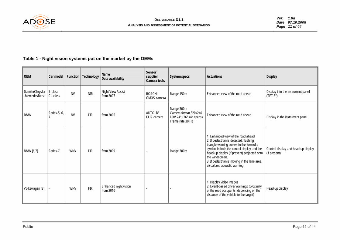
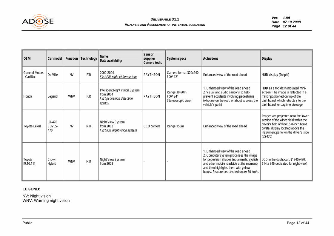
These systems are already offered on the market by Honda and Toyota, and they are based only on a FIR camera. The ADOSE approach (combination of low resolution FIR and high resolution CMOS sensors) would be quite novel on the market. Table 1 summarises the night vision systems put on the market by the main OEMs.
Public Page 11 of 44
DELIVERABLE D1.1 ANALYSIS AND ASSESSMENT OF POTENTIAL SCENARIOS
Ver. 1.8d Date 07.10.2008 Page 11 of 44
Table 1 - Night vision systems put on the market by the OEMs
OEM Car model Function Technology Name Date availability
Sensor supplier Camera tech.
System specs Actuations Display
DaimlerChrysler -MercedesBenz
S-class CL-class NV NIR Night View Assist
from 2007 BOSCH CMOS camera
Range 150m Enhanced view of the road ahead Display into the instrument panel (TFT 8'')
BMW Series-5, 6, 7 NV FIR from 2006 AUTOLIV
FLIR camera
Range 300m Camera format 320x240 FOV 24° (36° old specs) Frame rate 30 Hz
Enhanced view of the road ahead Display in the instrument panel
BMW [6,7] Series-7 WNV FIR from 2009 - Range 300m
1. Enhanced view of the road ahead 2. If pedestrian is detected, flashing triangle warning comes in the form of a symbol in both the control display and the head-up display (if present) projected onto the windscreen. 3. If pedestrian is moving in the lane area, visual and acoustic warning
Control display and head-up display (if present)
Volkswagen [8] - WNV FIR Enhanced night vision from 2010 - -
1. Display video images 2. Event-based driver warnings (proximity of the road occupants, depending on the distance of the vehicle to the target)
Head-up display
Public Page 12 of 44
DELIVERABLE D1.1 ANALYSIS AND ASSESSMENT OF POTENTIAL SCENARIOS
Ver. 1.8d Date 07.10.2008 Page 12 of 44
OEM Car model Function Technology Name Date availability
Sensor supplier Camera tech.
System specs Actuations Display
General Motors - Cadillac De Ville NV FIR 2000-2004
First FIR night vision system RAYTHEON Camera format 320x240 FOV 12° Enhanced view of the road ahead HUD display (Delphi)
Honda Legend WNV FIR Intelligent Night Vision System from 2004 First pedestrian detection system
RAYTHEON Range 30-90m FOV 24° Stereoscopic vision
1. Enhanced view of the road ahead 2. Visual and audio cautions to help prevent accidents involving pedestrians (who are on the road or about to cross the vehicle’s path)
HUD as a top dash mounted mini-screen. The image is reflected in a mirror positioned on top of the dashboard, which retracts into the dashboard for daytime stowage.
Toyota-Lexus LX-470 SUVLS-470
NV NIR Night View System from 2002 First NIR night vision system
CCD camera Range 150m Enhanced view of the road ahead
Images are projected onto the lower section of the windshield within the driver's field of view. 5.8-inch liquid crystal display located above the instrument panel on the driver’s side (LS470)
Toyota [9,10,11]
Crown Hybrid WNV NIR Night View System
from 2008 - -
1. Enhanced view of the road ahead 2. Computer system processes the image for pedestrian shapes (no animals, cyclists and other mobile roadside at the moment) and then highlights them with yellow boxes. Feature deactivated under 60 km/h.
LCD in the dashboard (1240x480, 614 x 346 dedicated for night view)
LEGEND:
NV: Night vision WNV: Warning night vision

Public Page 13 of 44
DELIVERABLE D1.1 ANALYSIS AND ASSESSMENT OF POTENTIAL SCENARIOS
Ver. 1.8d Date 07.10.2008 Page 13 of 44
3.2 Pre-crash safety systems
A Pre-crash system is an automobile safety system designed to reduce the damage caused by a collision. It represents the fastest growing new ADAS feature being introduced to passenger car models [12-21]. The evolution in pre-crash functionality can be divided into three consecutive steps defined by the set of actuators integrated. The steps are in the following order:
PRESET (PRE-crash SETting of algorithmic thresholds) It optimises the protective effects of the restraint system for the occupants if a crash should
occur. This is done by precise activation of the various pyrotechnical restraint media (pyrotechnical belt or an airbag), adapted to the situation and severity of the accident.
Detection range: 5m - Time to impact: 10-100 ms
PREFIRE (PRE-crash FIring of reversible Restraints) It places the occupants in a favourable initial position before the collision with the help of
reversible restraint devices, e.g. with the belt tensioner. This function does not interfere with the driving task of vehicle guidance.
Detection range: 15m - Time to impact: 100-300 ms
PREACT (PRe-crash Engagement of ACTive safety devices) It aims at mitigating the average crash severity when a crash is unavoidable by enhancing
the braking action by the driver after a collision warning (semi-autonomous modality) or by activating the braking system when the situation is already critical (autonomous modality); The function, as just defined, is also called COLLISION MITIGATION or EMERGENCY BRAKING. In the longer term PREACT avoids collisions via active intervention in the vehicle's operation (COLLISION AVOIDANCE).
Detection range: 70m (collision mitigation) - Time to impact: 500-2000 ms Examples of Pre-crash systems include:
Collision Mitigation Braking System (CMBS) from Honda Pre-Collision System (PCS) from Lexus Pre-Safe with Brake support from Mercedes-Benz S- and E-Class Distance Warning System/Preview Braking from Nissan/Infiniti Collision Warning System from Volvo Cars.
Table 2 summarise the Pre-crash safety systems currently offered on the market by the main OEMs. This state of the art is useful for the purpose of the current document for two basic reasons:
it highlights kinds of sensors and their combinations (sensor fusion) useful to improve the function performances and to reduce false alarms;
it summarises the actuations and the protection measures of the different pre-crash safety systems that will be considered in the definition of the ADOSE scenarios.

Public Page 14 of 44
DELIVERABLE D1.1 ANALYSIS AND ASSESSMENT OF POTENTIAL SCENARIOS
Ver. 1.8d Date 07.10.2008 Page 14 of 44
Regarding sensor fusion, there are two examples of combinations of different sensing technologies for frontal pre-crash safety systems which could represent a potential scenario for ADOSE:
Collision Warning with Auto Brake by Volvo
- Combination of LRR and a camera having respectively a detection range of 150m and 55m
- In general the goal of this data fusion is to combine the longitudinal accuracy in distance and speed provided by the radar sensors with the lateral accuracy provided by the video system
- Specifically, one of the main advantages of the camera in the Volvo system is the possibility of detecting stationary vehicles and warning the driver while maintaining a low false-alarm level
Advanced Pre-crash safety systems by Lexus
- Combination of LRR and a stereo NIR camera having respectively a detection range of 150m and 25m
- Pedestrian detection is performed by the CCD camera Concerning pre-crash safety systems for side impact, a survey revealed that, at the moment, there seems to be no OEM planning to integrate PreCrash Safety Systems for Side Impact into one of own vehicles. However, R&D activities are in progress in that area involving major industrial players. For instance, the EU-project APROSYS [22] works, in the context of SP6, on side impact issues with Daimler involved. Tier1s like Denso already offer sensors for side impact (e.g. an airbag side impact sensor), but they are crash and not pre-crash sensors. Another investigation into the possibilities to use 3D camera sensors for side crash prediction was performed by Renault in the subproject UseRCams of PReVENT [15, 16].

Public Page 15 of 44
DELIVERABLE D1.1 ANALYSIS AND ASSESSMENT OF POTENTIAL SCENARIOS
Ver. 1.8d Date 07.10.2008 Page 15 of 44
Table 2 - Pre-crash safety systems put on the market by the OEMs
OEM Car model Functions Pre-crash safety system Sensor tech. System specs Actuations
DaimlerChrysler -MercedesBenz
S-class E-class CL
Front PF CM
PRE-SAFE + Brake Assist PLUS (BAS PLUS) from 2002 (Pre-Safe, S-class) Mercedes-Benz is credited with being the forward developer of the pre-crash system.
1 LRR and 2 SRR SRR 24GHz LLR 77GHz Range 30m (SRR), 150m (LRR) FOV 80° (SRR), 9° (LRR)
1. Warning on the instrument cluster 2. Acoustic warning 3. Pretensioning seatbelts 4. Adjusting seat positions including rear seats (if installed) 5. Inflating the air chambers in the dynamic multi-contour seats (optional) to support the driver and front passenger and press them more firmly into their seats. 6. Closure open windows and sunroof (if vehicle skids) 7. Braking-power support is available as soon as the brake pedal is operated 8. Automatic brake (slows the car down at a rate of up to 0.4 g [around 4 m/s], correspondign to araound 40% of total braking power)
Ford-Volvo S80 Front CW+BS
Collision Warning and Brake Support (CWBS) from 2006 LRR Moving vehicles only
FOV 15°
1. Visual warning (red light) by head-up display 2. Acoustic warning (buzzer) 3. Pre-charging of brakes 4. Support to increase brake intensity
Ford-Volvo [23,24]
S80, V70, XC70
Front CW+AB
Collision Warning with Auto Brake (CWAB) from 2008 LRR + Camera
Moving + stationary vehicles, 0.5 G braking, Range 150m (LRR), 55m (camera)
1. Red warning light flashes in the head-up display 2. Acoustic warning 3. Activation brake support (pre-charging of brakes) 4. Automatic braking in case of rear-end collision
Honda CR-V SUV Accord
Front PF CM
Collision Mitigation Braking System (CMBS) from 2007 LRR
CMBS active with speeds higher than 15 km/h, and when the speed difference between it and the vehicle in front exceeds 15 km/h. Range 4-100m FOV 16°
1. Acoustic warning and visual "Brake" alert on instrument cluster 2. Pretensioning of seatbelts, light braking 3. Strong seatbelt retraction and strong braking

Public Page 16 of 44
DELIVERABLE D1.1 ANALYSIS AND ASSESSMENT OF POTENTIAL SCENARIOS
Ver. 1.8d Date 07.10.2008 Page 16 of 44
OEM Car model Functions Pre-crash safety system Sensor tech. System specs Actuations
Honda-Acura RL Front PF CM
Collision Mitigation Braking System (CMBS) from 2006 LRR
CMBS active with speeds higher than 15 km/h, and when the speed difference between it and the vehicle in front exceeds 15 km/h. Range 4-100m FOV 16°
1. Acoustic warning and visual alert on instrument cluster 2. Pretensioning of seatbelts, light braking 3. Strong seatbelt retraction and strong braking
Nissan Skyline Fuga Cima
Front CM Intelligent Brake Assist (IBA) Laser radar 0.5 G braking force 1. Acoustic warning
2. Activation of brakes
Nissan-Infiniti [25] FX
Front PF CM
Intelligent Brake Assist (IBA) Brake-Operated Pre-crash Seatbelt System from 2009
Laser radar 0.5 G braking force
If obstacle is detected (IBA): 1. Acoustic warning 2. Activation of brakes If emergency braking is detected by the speed and amount of the brake pedal operation (brake pedal stroke sensor): 1. Activation of IBA 2. Pretensioning of seatbelts
Mazda MPX, CX-7 Front PF CM
Pre-Crash Safety System from 2006 LRR -
1. Buzzer and warning light 2. Light braking to alert driver 3. Pretensioning of seatbelts 3. Automatic braking
Toyota-Lexus LS, GS, ES, IS
Front PF CM
Pre-Collision System (PCS) from 2005 LRR -
1. Warning (lights flash and buzzers) 2. Preparation Brake assist 3. Pretensioning of seatbelts 4. Brake assist automatically engages the brakes

Public Page 17 of 44
DELIVERABLE D1.1 ANALYSIS AND ASSESSMENT OF POTENTIAL SCENARIOS
Ver. 1.8d Date 07.10.2008 Page 17 of 44
OEM Car model Functions Pre-crash safety system Sensor ech. System specs Actuations
Toyota-Lexus [26-29] LS
Front+rear PF CM
Advanced Pre-Crash Safety (PCS) or Advanced Pre-Collision System (APCS): Advanced Obstacle Detection System + Driver Monitoring System + Emergency Steering Assist + Rear Pre-Crash Safety system from 2008
Front: LRR + Stereo NIR camera Rear: mW radar Driver monitoring: NIR camera (on top of the steering column cover)
Also pedestrians detection Range 25m (stereocamera) CCD cameras (obstacle detection) CCD camera + six built-in near infrared LEDs (driver monitoring)
Front: 1. Warning buzzer and red "BRAKE" alert 2. Preparation Brake assist 3. Priming Adaptive Variable Suspension to reduce nose-dive 4. Priming Emergency steering assist 5. Pretensioning of seatbelts 6. Brake assist automatically engages the brakes Rear: 1. Warning (lights flash) 2. Adjusting the front headrests (upward by up to 60 mm, and forward by up to 25 mm) Driver monitoring: 1. Warning light and buzzer 2. Gentle braking (driver not looking ahead detected by the driver monitoring system)
LEGEND:
Front: Frontal Pre-crash safety system Rear: Rear Pre-crash safety system PF: Prefire PS: Pre-set CM: Collision mitigation (or emergency braking) CW: Collision warning LRR: Long range radar SRR: Short range radar
Public Page 18 of 44
DELIVERABLE D1.1 ANALYSIS AND ASSESSMENT OF POTENTIAL SCENARIOS
Ver. 1.8d Date 07.10.2008 Page 18 of 44
4. STUDY ON SCENARIOS AND SELECTION FOR ADOSE
4.1 Scenarios addressed in other reference projects
At the WP1 workshop in Vienna (March 4, 2008) a review of the scenarios used in PReVENT, SAFESPOT and WATCH-OVER was presented as reference, explaining their more or less complex structure. Conclusions were drawn for ADOSE taking into account that the project is technology oriented addressing the development of specific novel sensors. WATCH-OVER [30, 31] The goal of the project is the design and development of a cooperative system for the prevention of accidents involving vulnerable road users in urban and extra-urban areas. The definition of scenarios in WATCH-OVER followed an iterative approach to guarantee as much as possible the identification of all relevant scenarios and consequently of all relevant use cases [30]. The overall list of scenarios was made combining the outcomes of three steps:
1. Accident analysis 2. Expert brainstorming 3. Methodical analysis
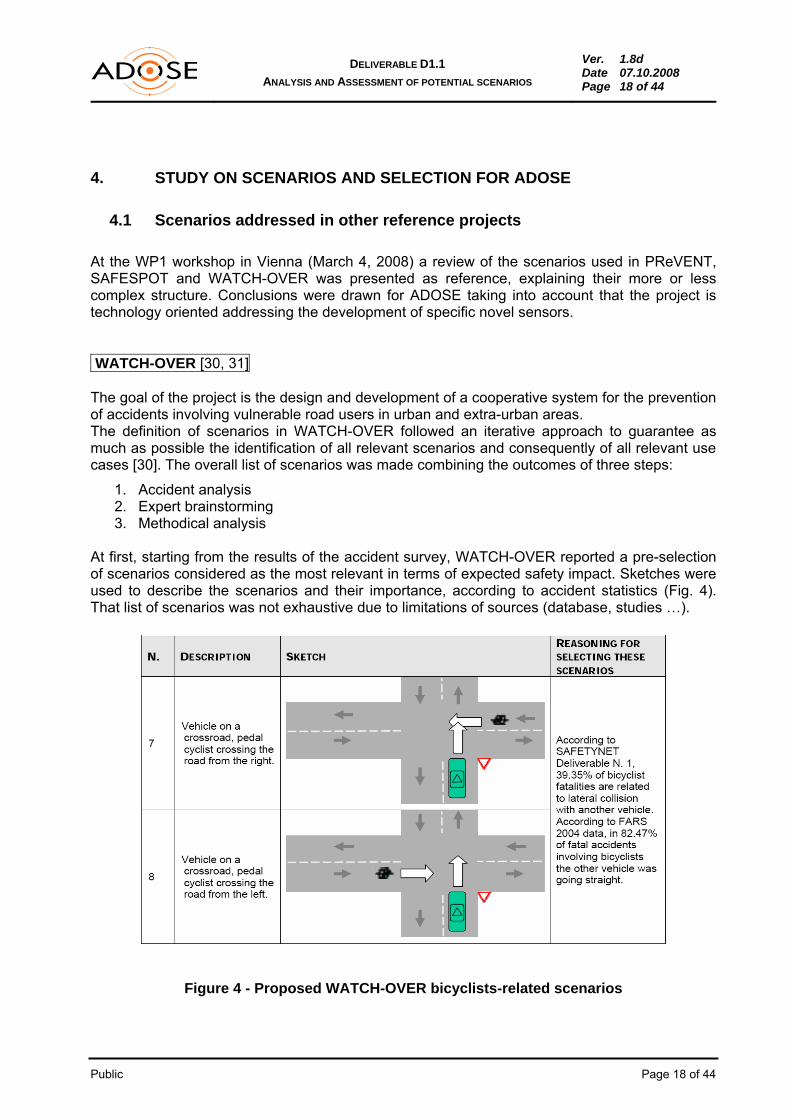
At first, starting from the results of the accident survey, WATCH-OVER reported a pre-selection of scenarios considered as the most relevant in terms of expected safety impact. Sketches were used to describe the scenarios and their importance, according to accident statistics (Fig. 4). That list of scenarios was not exhaustive due to limitations of sources (database, studies …).
Figure 4 - Proposed WATCH-OVER bicyclists-related scenarios

Public Page 19 of 44
DELIVERABLE D1.1 ANALYSIS AND ASSESSMENT OF POTENTIAL SCENARIOS
Ver. 1.8d Date 07.10.2008 Page 19 of 44
Then an expert brainstorming session analysed the outcomes of the accident survey and extended the already identified cases completing part of the relevant scenarios by adding relevant and related cases.
Last, a systematic approach enabled the identifications of 72 scenarios to describe all types of accidents considering category, type of road and relative trajectories.
Input for ADOSE The main motivation of the project is not ‘functional’ but ‘technological’: ADOSE does not aim at developing new safety functions, but novel or enhanced sensors with higher performances and/or lower cost. For this reason the accident statistics have been omitted in ADOSE and the list of scenarios has been defined starting from the outcomes of the main safety projects including WATCH-OVER.
PReVENT [2-3, 15-16, 32-34, 36] PReVENT aimed at the development of functions and applications needed to make an electronic safety zone around the vehicle. The project applications target at better understanding of the driving environment in order to inform, warn and support the driver, and ultimately protect vehicle occupants in accident situations. There are four vertical activities:
• Safe speed and safe following (SASPENCE and WILLWARN) • Lateral control support (LATERAL SAFE and SAFELANE) • Intersection safety (ITERSAFE) • Vulnerable road users and collision mitigation (APALACI, COMPOSE, UseRCams) Fig. 5 shows a typical scenario defined within one of the PReVENT vertical subprojects, UseRCAMs, which is the only one devoted to the development of a novel sensor. In PReVENT the definition of scenarios is often anticipated by the accident analysis [15]. The UseRCAMs focus is on the development of an affordable active 3D sensor, which is vital in providing improved obstacle detection and classification at a short range. The sensor is especially suitable for the collision mitigation, protection of vulnerable road users and blind spot detection.

Public Page 20 of 44
DELIVERABLE D1.1 ANALYSIS AND ASSESSMENT OF POTENTIAL SCENARIOS
Ver. 1.8d Date 07.10.2008 Page 20 of 44
Figure 5 - Typical scenario defined in PReVENT, UseRCAMs subproject. Basic description and reasoning for accident scenarios to be handled by 3D camera are done and then requirements are derived from scenarios in an understandable form [15, 16]. Analysis of scenarios and requirements in PReVENT for collision mitigation, pre-crash and vulnerable road users [32] has been studied in detail for the ADOSE purposes. In figure 6 the APALACI scenario is summarised for advanced pre-crash and collision mitigation [33, 34]. The classification of scenarios including side-impact for vision-type sensors is e.g. described in [35] (“Vehicle Electronics” in Baden-Baden 2007). The concept of sensor data fusion for advanced driver assistance systems is elaborated in the subproject ProFusion [2, 36]. The concept that functional safety is only achievable by sensor data fusion is completely common in the eSafety community and it is a major item of investigation in many conferences [37]. Although this aspect is intentionally not the primary concern in ADOSE which focuses on novel sensor technology, it supports the justification of the ADOSE approach to address a diverse set of novel sensors, the applicability of which for the different scenarios is summarized in a coarse manner in the scenarios tables under “Potential and restrictions of sensors”.

Public Page 21 of 44
DELIVERABLE D1.1 ANALYSIS AND ASSESSMENT OF POTENTIAL SCENARIOS
Ver. 1.8d Date 07.10.2008 Page 21 of 44
Figure 6 - Typical scenario defined in PReVENT, APALACI subproject
Input for ADOSE: The simplified model of scenarios for ADOSE was inspired by the PReVENT approach. In particular the following PReVENT scenarios were analysed in detail:
Pre-fire, Pre-set and Collision mitigation (APALACI) Pedestrian recognition (APALACI) Front-end collisions (UseRCams) Side pre-crash (UseRCams)
The suitability of ADOSE sensors for each scenario is argued in a coarse manner in the scenarios tables under “Potential and restrictions of sensors”, which follows in a very simplified manner the PReVENT approach which was decided to be adequate for the goal of ADOSE.
Concerning description and calculations for sensor requirements and specifications, it was decided to take a similar approach in ADOSE with a table format: graphical description of constraints and environment, calculations following as “details” the rational for the requirements.
SAFESPOT [38] SAFESPOT takes a very broad view on vehicle/road safety and includes a large set of possible scenarios, taking into account in-vehicle systems collecting all type of relevant data and being

Public Page 22 of 44
DELIVERABLE D1.1 ANALYSIS AND ASSESSMENT OF POTENTIAL SCENARIOS
Ver. 1.8d Date 07.10.2008 Page 22 of 44
able to perform safety and emergency functions (partially autonomous and preparatory) as well as co-operative systems functions by exchanging data with other vehicles and the infrastructure, and processing them for improving road safety. In particular the subproject SP1 SAFEPROBE is developing the vehicle-based subsystem that performs the in-vehicle sensing, the in-vehicle fusion of data into a local dynamic map of the environment and the communication with other vehicles and infrastructure subsystems enabling the applications developed by SP4 and SP5 subprojects. SAFEPROBE followed a well defined methodology for the scenario title selection. The scenario-merging process defined 85 scenario titles, of which 35 were selected as the most relevant. These scenarios were then prioritised and 15 scenarios with the highest priority were selected.
Input for ADOSE The discussion on the extensive analysis provided by SAFESPOT/SAFEPROBE revealed the following results:
• SAFESPOT is much more complex: it targets at all types of road users, including vulnerable ones, and it includes sensor fusion, high level decisions and algorithms, co-operative systems (Car2Car, infrastructure information, wireless communications), which is far beyond ADOSE goals.
• Deliverable D1.2.1 “Vehicle probe use cases and test scenarios” of SAFEPROBE [38] covers one group of scenarios which can be applied to ADOSE (usable as test scenarios too) because they can be handled by in-vehicle sensing platforms only, without requiring higher level services based on co-operative systems and communications car-to-car or vehicle-to-infrastructure (in both directions).
• Review of SAFEPROBE scenarios (15) was done to compare them with ADOSE simpler ones. ADOSE scenarios fit partially about 50% of SAFEPROBE scenarios.
The SAFEPROBE driving environment has been specified by defining some general driving attributes (many more than would be adequate for ADOSE) such as: • Area types
o Motorway/highway o Urban o Rural
• Weather Conditions o Fog o Rain o Wind o Snow, Ice
• Road structure o Tunnel o Bridge
• Road segment / spot geometry o Curved road o Straight road o Intersection/junction o Roundabout o Pedestrian crossing o Signalled o Un-signalled
• Visibility conditions and diurnal cycle o Day

Public Page 23 of 44
DELIVERABLE D1.1 ANALYSIS AND ASSESSMENT OF POTENTIAL SCENARIOS
Ver. 1.8d Date 07.10.2008 Page 23 of 44
o Night o reduced (fire/smoke/blinded by sun)
• General traffic conditions o Dense o Free o Congestion
Input for ADOSE Looking at the in-vehicle sensor potentials and restrictions, the following subset of driving attributes was decided to apply in ADOSE, since only the nearby crash situations have to be handled by the in-vehicle sensors:
Area types (characterized by typical distance, timing constraints and average general traffic conditions): - Urban - Extra-Urban
Weather and visibility conditions: they characterize the testing environments and the sensor applicability, and they are the basis for the required sensor combinations to be applied.
Road structure (tunnel): not of primary interest (it may indirectly influence environmental conditions, it implies night condition at daytime, etc.)
The “reduced scenario set” (first ones out of 15 selected) [38] of SAFEPROBE looks like Fig. 7.
Figure 7 - SAFESPOT: 7 of 15 selected scenarios
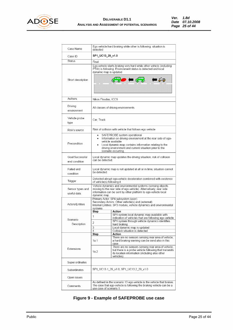
A typical scenario and related use case of SAFEPROBE are reported in Fig. 8 and 9.

Public Page 24 of 44
DELIVERABLE D1.1 ANALYSIS AND ASSESSMENT OF POTENTIAL SCENARIOS
Ver. 1.8d Date 07.10.2008 Page 24 of 44
Figure 8 - Example of scenario in SAFEPROBE.
Public Page 25 of 44
DELIVERABLE D1.1 ANALYSIS AND ASSESSMENT OF POTENTIAL SCENARIOS
Ver. 1.8d Date 07.10.2008 Page 25 of 44
Figure 9 - Example of SAFEPROBE use case

Public Page 26 of 44
DELIVERABLE D1.1 ANALYSIS AND ASSESSMENT OF POTENTIAL SCENARIOS
Ver. 1.8d Date 07.10.2008 Page 26 of 44
Input for ADOSE The set of scenarios is considerably reduced to the ego-vehicle/obstacle case for rear, front and side impact scenarios, some of them allowing crash avoidance/mitigation, some (like side impact) only pre-crash warning/preparation. More complex traffic situations need not to be handled – this is task of higher level services of road safety systems (as addressed in the reference projects, which may take into account some features of the novel sensors and sensor combinations in the future). The primary goal of ADOSE is to provide vehicles with a set of reliable sensors which can be produced cost-effective on a large scale and easily be implemented.
4.2 Selected scenarios in ADOSE
After having discussed the available scenarios defined within PReVENT, SAFESPOT and WATCH-OVER, at the WP1 workshop in Vienna, it was decided - because of the major difference of ADOSE goals (restricted to on-board sensors and ego-vehicle, no co-operative systems, no car-to-car or car-to-infrastructure communication) - to focus on reasonable, simpler scenarios adequate for the ADOSE R&D and validation objectives. Two groups of scenarios were selected, depending on the restrictions imposed by the sensor types, timing constraints, sensor appliance and interaction with the ego-vehicle only:
• Collision avoidance • Pre-crash warning/preparation Driving environments are either urban or extra-urban. Vehicle-related impact scenarios are:
• Front impact • Side impact • Rear impact
The selected scenarios (with the responsible partner) are as follows:
Group 1, Collision avoidance:
1.1 Collision Avoidance Extra-Urban Areas incl. VRUs (BOSCH) 1.2 Collision Avoidance Urban Areas incl. VRUs (BOSCH)
Group 2, Pre-crash warning/preparation:
2.1 Pre-Crash Warning/Preparation Front Impact (CRF) 2.2 Pre-Crash Warning/Preparation Side Impact (ARC) 2.3 Pre-Crash Warning/Preparation Rear Impact (MMSE)
4.3 Classification of scenarios
The classification of the scenarios was structured by a list of items, selected from the examples of related reference projects and reduced as far as reasonable for the ADOSE purposes. The scenarios are described in a sensor-independent way by the following items:
Public Page 27 of 44
DELIVERABLE D1.1 ANALYSIS AND ASSESSMENT OF POTENTIAL SCENARIOS
Ver. 1.8d Date 07.10.2008 Page 27 of 44
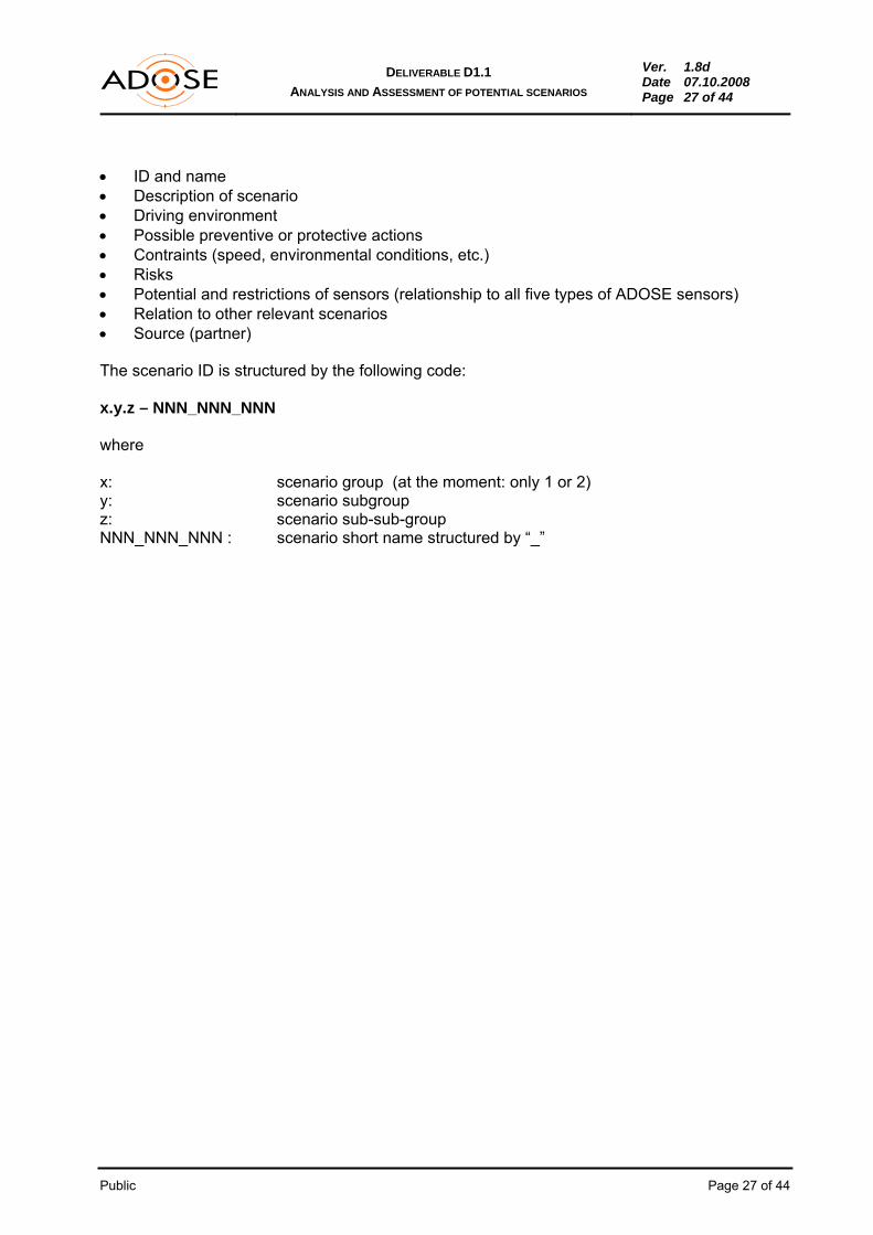
• ID and name • Description of scenario • Driving environment • Possible preventive or protective actions • Contraints (speed, environmental conditions, etc.) • Risks • Potential and restrictions of sensors (relationship to all five types of ADOSE sensors) • Relation to other relevant scenarios • Source (partner) The scenario ID is structured by the following code: x.y.z – NNN_NNN_NNN where x: scenario group (at the moment: only 1 or 2) y: scenario subgroup z: scenario sub-sub-group NNN_NNN_NNN : scenario short name structured by “_”

Public Page 28 of 44
DELIVERABLE D1.1 ANALYSIS AND ASSESSMENT OF POTENTIAL SCENARIOS
Ver. 1.8d Date 07.10.2008 Page 28 of 44
5. SCENARIO GROUP DESCRIPTIONS
5.1 Scenarios Group 1: Collision Avoidance
5.1.1 Scenario 1.1: Collision Avoidance in Extra-Urban Areas including VRUs
ID: 1.1.0 – CA_EXT Name: Collision-Avoidance-Extra-Urban
Description of scenario: Collision detection (object/obstacle in ego lane) at long distances for collision warning/intervention (beyond emergency braking). Relevant objects/obstacles are:
Moving and stationary vehicles Vulnerable road users (less in extra-urban areas) Animals (small animals like snakes or cats excluded) Other obstacles (cold objects like lost freights)
Driving Environment: extra-urban, no motorway
Possible preventive or protective actions: a. Collision warning (no autonomous avoiding like braking or/and swerving)
possibly with brake assist (to allow shorter braking distances) b. Steering intervention or emergency braking
Constraints: Object size > 0.5m x 1.0m Speed: 50km/h < v < 100km/h Environment:
o All lighting conditions o All road types (except urban and motorways) o All weather conditions
Risks: For intervening system: high risk in case of false alarm ---> sensor fusion is necessary
Potential and Restrictions of sensors: FIR-add-on:
Max. detection range: 120 m Min. reaction time: 160 ms Reduced performance in heavy rain, spindrift, fog Reduced performance at warm environmental conditions Only warm objects (VRU, animals) ---> no detection of cold objects and vehicles
MFOS:
Application as NIR camera with a detection range of about 150m Improved performance in detecting crossing and preceding vehicle in night conditions

Public Page 29 of 44
DELIVERABLE D1.1 ANALYSIS AND ASSESSMENT OF POTENTIAL SCENARIOS
Ver. 1.8d Date 07.10.2008 Page 29 of 44
Complementary information on visibility level (rain, fog, twilight, …) to enhance the sensor processing or to deactivate them in case of unreliable output
3DCAM:
Low detection range due to laser power limitation for eye safety: about 25 m Reduced performance in spindrift, fog
HR-TAG:
Max. detection range: 100-150 m (active tag), 25-100 m (passive tag) Max. detection time: 100 ms Field of view: 120° (short range) / 20° (long range) Reduced performance in heavy rain Radar in harmonic operation: detection of objects equipped with HR-Tag (VRUs) Radar in normal operation: detection of other objects (animals, lost freight and other
vehicles)
SRS: No potential with the current sensor configuration (FOV, baseline, pixel size, ...) since
the detection range is only 6 meters. Relations: ---
Source: Bosch
5.1.2 Scenario 1.2: Collision Avoidance in Urban Areas including VRUs
ID: 1.2.0 – CA_INT Name: Collision-Avoidance-Intra-Urban
Description of scenario: Collision detection (object/obstacle in ego lane) at medium distances for collision warning/intervention (beyond emergency braking). Relevant objects/obstacles are:
Moving and stationary vehicles Vulnerable road users Animals (less in urban areas) Other obstacles (cold objects like lost freights)
Driving Environment: urban
Possible preventive or protective actions: a) Collision warning (no autonomous avoiding like braking or/and swerving)
possibly with brake assist (to allow shorter braking distances) b) Steering intervention and/or emergency braking

Public Page 30 of 44
DELIVERABLE D1.1 ANALYSIS AND ASSESSMENT OF POTENTIAL SCENARIOS
Ver. 1.8d Date 07.10.2008 Page 30 of 44
Constraints: Object size > 0.5m x 1.0m Speed: 10km/h < v < 70km/h Environment:
o All lighting conditions o All road types (urban) o All weather conditions
Risks: For intervening system: high risk in case of false alarm ---> sensor fusion is necessary
Potential and Restrictions of sensors: FIR add-on:
Max. detection range: 120 m Min. reaction time: 160 ms Reduced performance in heavy rain, spindrift, fog Reduced performance in complex scenarios Reduced performance at warm environmental conditions Only warm objects (VRU, animals) -> no detection of cold objects and vehicles Limited angular range Reduced detection rate due to low sensor location
MFOS:
Application as NIR camera with a detection range of about 150m Improved performance in detecting crossing and preceding vehicle in night conditions Complementary information on visibility level (rain, fog, twilight, …) to enhance the
sensors processing or to deactivate them in case of unreliable output 3DCAM:
Max. detection range: about 25 m Reduced performance in spindrift, fog Good angular range
HR-TAG:
Max. detection range: 100-150 m (active tag), 25-100 m (passive tag) Max. detection time: 100 ms Field of view 120° (short range) / 20° (long range) Reduced performance in heavy rain Radar in harmonic operation: detection of objects equipped with HR-Tag (VRUs) Radar in normal operation: detection of other objects (animals, lost freight and other
vehicles) SRS:
No potential with the current sensor configuration (FOV, baseline, pixel size, ..) since the detection range is only 6 meters.

Public Page 31 of 44
DELIVERABLE D1.1 ANALYSIS AND ASSESSMENT OF POTENTIAL SCENARIOS
Ver. 1.8d Date 07.10.2008 Page 31 of 44
Relations: ---
Source: Bosch
5.2 Scenarios Group 2: Pre-Crash Warning/Preparatory Actions
5.2.1 Scenario 2.1: Pre-Crash Warning/Preparation Front Impact
ID: 2.1.0 – PCW_FR Name: Pre-Crash_Front
Description of scenario: Colllision detection (object/obstacle) at short distances and crash prediction for Pre-Crash warning / preparation for front impact (Pre-fire and Pre-set applications). Relevant moving or standing objects/obstacles are:
Vehicles Bicycle and pedestrian Small objects (trees, poles, …)
Driving Environment: Urban, extra-urban
Possible preventive or protective actions: a) Pre-Crash warning (e.g. an acoustic warning signal) b) Collision mitigation c) Pre-tensioning of safety belts d) Pre-setting of air bags
Constraints: Object size > 0.2m x 1.0m Speed: v < 70km/h Environment:
o All lighting conditions o All road types except highways o All weather conditions
Time constrains: 1) Activation time before an impact for airbag pre-setting is 30ms 2) Activation time before an impact to retract front seatbelts is about 100-300ms
Risks:
Pre-tensioning of seatbelts and airbag pre-setting are not very risky in case of false alarm.
Potential and Restrictions of sensors: FIR add-on:
No potential with the specified FOV, only warm objects to be detected, additional sensor is necessary for classification (sensor fusion)

Public Page 32 of 44
DELIVERABLE D1.1 ANALYSIS AND ASSESSMENT OF POTENTIAL SCENARIOS
Ver. 1.8d Date 07.10.2008 Page 32 of 44
MFOS: Classification of traffic obstacles Good lateral resolution Detection of lane geometry and features Complementary information on weather condition (mainly rain e.g. to optimise the
braking distance) 3DCAM:
Max detection range: 25 m Classification of traffic obstacles and detection of their motion Good lateral resolution Reduced performance in spindrift and fog
HR-TAG:
Max. detection range: 100-150 m (active tag), 25-100 m (passive tag) Max. detection time: 100 ms Field-of-view 120° (short range) / 20° (long range) Reduced performance in heavy rain Radar in harmonic operation: detection of objects equipped with HR-Tag (VRUs) Radar in normal operation: detection of other objects (animals, lost freight and other
vehicles) SRS:
Low potential with the current sensor configuration (FOV, baseline, pixel size, ..) since the detection range is only 6 meters. Range could be extended with a different configuration.
Relations: ----
Source: CRF/VTT
5.2.2 Scenario 2.2: Pre-Crash Warning/Preparatory Actions Side Impact
ID: 2.2.0 – PCW_SI Name: Pre-Crash_Side Description of scenario: Collision detection (objects, obstacles) at short distance and crash prediction for Pre-Crash warning / preparation for side impact (Pre-fire and Pre-set applications). Relevant objects/obstacles are:
Moving vehicles Other moving obstacles (like a motorbike, …) Stationary obstacles (e.g. trees)
Driving Environment: Urban

Public Page 33 of 44
DELIVERABLE D1.1 ANALYSIS AND ASSESSMENT OF POTENTIAL SCENARIOS
Ver. 1.8d Date 07.10.2008 Page 33 of 44
Possible preventive or protective actions: Pre-Crash warning (e.g., an acoustic warning signal) Pre-tensioning of safety belts Pre-setting of air bags Stopping flow of fuel
Constraints:
Object size ≥ 0.5m x 1.0m Speed: v < 60km/h Environment:
o All lighting conditions o All road types except highways o All weather conditions
Timing constrains: 1) Activation time before an impact for airbag pre-setting is 30ms 2) Time before an impact to retract front seatbelts is about 100-300ms
Impact angle: 90° for vehicle to vehicle impact (e.g. at intersection) Sensor mounting: Near the B-pillar or in the front door of the car
Risks:
Pre-tensioning of seatbelts and airbag pre-setting are not risky in case of false alarm Stopping flow of fuel is very risky in case of false alarm ---> sensor fusion is necessary
Potential and Restrictions of sensors: FIR-add-on:
No potential with the specified mounting position, FOV too small (+/- 12°), detection only of warm objects, additional sensor for classification is necessary
MFOS:
MFOS concept is suitable and competitive only with frontal mounting position; no potential for Pre-crash_Side in case of limited field of view targeting frontal area monitoring (high beam assist, night vision enhancement).
3DCAM:
Good potential for the limited detection range required by the scenario Good angular range Reduced performance in spindrift and fog
HR-TAG:
Can not be detected with forward-looking radar SRS:
Max. detection range: 6m Max. field-of-view: 30° Temporal resolution of 3D information by SRS : 5ms

Public Page 34 of 44
DELIVERABLE D1.1 ANALYSIS AND ASSESSMENT OF POTENTIAL SCENARIOS
Ver. 1.8d Date 07.10.2008 Page 34 of 44
Reduced performance in heavy rain, spin drift, snow and fog Ego-vehicle not moving, only objects moving relative to the ego-vehicle can be
detected
Relations: Maybe to scenarios PCW_RE_U
Source: ARC
5.2.3 Scenario 2.3: Pre-Crash Warning/Preparatory Actions Rear Impact
5.2.3.1 Scenario 2.3.1: Pre-Crash Warning/Preparatory Actions Rear Impact - Urban
ID: 2.3.1 – PCW_RE_U Name: Pre-Crash_Rear_Urban
Description of scenario: Rear Impact detection and (automatic) protective actions released. Relevant objects/obstacles are:
Any vehicles approaching with danger of crashing from behind Driving Environment: Urban with ego vehicle not moving
Possible preventive or protective actions: Warning driver (e.g. flashing hazard lights) Preparation of head/neck protection by adjustment of front headrests Preparation (pretensioning) of safety belts Stopping flow of fuel Brake management (keep brake or release brake)
Constraints: Min reaction time: 500 ms (@ 10m and 70 km/h) Distance: medium (10-20 m) Speed: moderate (urban) 10km/h < v < 70km/h Road conditions: all Weather conditions: all Object size: > 0.5m x 1.0m
Risks:
Warning too frequent or false-positive release of actions Stopping flow of fuel is risky in case of false alarm
Potential and Restrictions of sensors: FIR-add-on:
No potential with specified mounting position, FOV too small (+/- 12°), detection only of warm objects, additional sensor for classification necessary
MFOS:

Public Page 35 of 44
DELIVERABLE D1.1 ANALYSIS AND ASSESSMENT OF POTENTIAL SCENARIOS
Ver. 1.8d Date 07.10.2008 Page 35 of 44
MFOS concept is suitable and competitive only with frontal mounting position; no potential for Pre-crash_Rear.
3DCAM:
Good potential for the limited detection range (10-20m) required by the scenario Good angular range Good temporal resolution Reduced performance in spindrift and fog
HR-TAG: Added value of HR-TAG is a better detection of VRUs which are not considered in the
present scenario SRS: Low potential with the current sensor configuration (FOV, baseline, pixel size, ..) since
the detection range is only 6 meters. Range could be extended with a different configuration.
Relations:
Source: MM
5.2.3.2 Scenario 2.3.2: Pre-Crash Warning/Prep. Actions Rear Impact – High Way
ID: 2.3.2 – PCW_RE_H Name: Pre-Crash_Rear_Highway
Description of scenario: Rear Impact detection and (automatic) protective actions released. Relevant objects/obstacles are:
Any vehicles approaching with danger of crashing from behind
Driving Environment: High way (platooning) ego car slowing down and following car speeding up
Possible preventive or protective actions: Warning driver (e.g. flashing hazard lights) Preparation of head/neck protection by adjustment of front headrests Preparation (pretensioning) of safety belts Stopping flow of fuel
Constraints: Min reaction time: 450 ms (@ 10m and 80 km/h) Distance: medium (10-20 m) Speed: moderate (urban like) 10 km/h < v < 80 km/h Road conditions: all Weather conditions: all Object size: > 0.5m x 1.0m

Public Page 36 of 44
DELIVERABLE D1.1 ANALYSIS AND ASSESSMENT OF POTENTIAL SCENARIOS
Ver. 1.8d Date 07.10.2008 Page 36 of 44
Risks: Warning too frequent or false-positive release of actions Stopping flow of fuel is risky in case of false alarm
Potential and Restrictions of sensors: FIR- add-on:
No potential with specified mounting position, FOV too small (+/- 12°), detection only of warm objects, additional sensor for classification necessary
MFOS:
No potential due to the mounting position 3DCAM:
Good potential for the limited detection range (10-20m) required by the scenario Good angular range Good temporal resolution Reduced performance in spindrift and fog
HR-TAG: Added value of HR-TAG is a better detection of VRUs which are not considered in the
present scenario SRS: Low potential with the current sensor configuration (FOV, baseline, pixel size, …)
since the detection range is only 6 meters. Range could be extended with a different configuration.
Relations: ---
Source: MM
5.2.3.3 Scenario 2.3.3: Pre-Crash Warning/Preparatory Actions Rear Impact – ExtraUrban and Country Lanes
ID: 2.3.3 – PCW_RE_C Name: Pre-Crash_Rear_ExtraUrban
Description of scenario: Rear Impact detection and (automatic) protective actions released Relevant objects/obstacles are:
Any vehicles approaching with danger of crashing from behind
Driving Environment: Extraurban and country lanes (with blind bends) ego vehicle slow, following vehicle moderate or higher speed
Public Page 37 of 44
DELIVERABLE D1.1 ANALYSIS AND ASSESSMENT OF POTENTIAL SCENARIOS
Ver. 1.8d Date 07.10.2008 Page 37 of 44
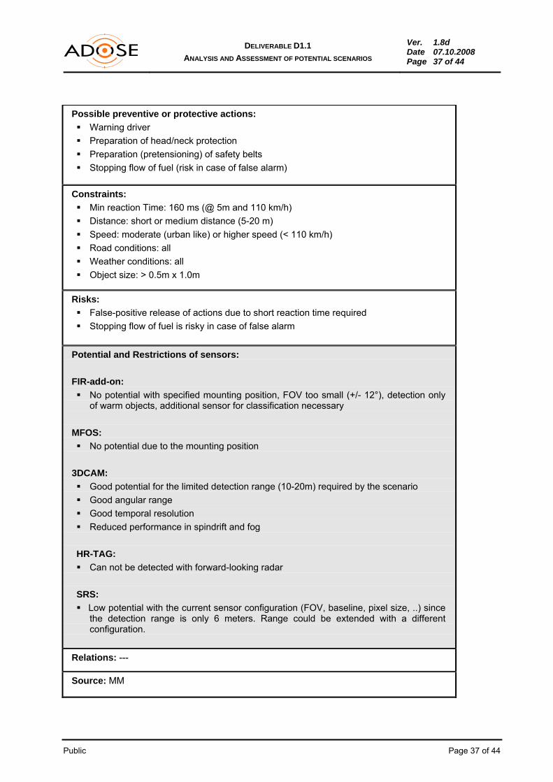
Possible preventive or protective actions: Warning driver Preparation of head/neck protection Preparation (pretensioning) of safety belts Stopping flow of fuel (risk in case of false alarm)
Constraints: Min reaction Time: 160 ms (@ 5m and 110 km/h) Distance: short or medium distance (5-20 m) Speed: moderate (urban like) or higher speed (< 110 km/h) Road conditions: all Weather conditions: all Object size: > 0.5m x 1.0m
Risks: False-positive release of actions due to short reaction time required Stopping flow of fuel is risky in case of false alarm
Potential and Restrictions of sensors: FIR-add-on:
No potential with specified mounting position, FOV too small (+/- 12°), detection only of warm objects, additional sensor for classification necessary
MFOS:
No potential due to the mounting position
3DCAM: Good potential for the limited detection range (10-20m) required by the scenario Good angular range Good temporal resolution Reduced performance in spindrift and fog
HR-TAG: Can not be detected with forward-looking radar
SRS: Low potential with the current sensor configuration (FOV, baseline, pixel size, ..) since
the detection range is only 6 meters. Range could be extended with a different configuration.
Relations: ---
Source: MM

Public Page 38 of 44
DELIVERABLE D1.1 ANALYSIS AND ASSESSMENT OF POTENTIAL SCENARIOS
Ver. 1.8d Date 07.10.2008 Page 38 of 44
6. SCENARIO/SENSOR TECHNOLOGY MATRIX
The scenario/sensor-technology matrix shown in Table 3 provides a preliminary overview over scenarios and sensor potential.
Table 3 - Scenario/sensor-technology matrix
SENSOR SCENARIO
FIR MFOS 3DCAM HR-PTag HR-A Tag SRS
1.1 Collision Avoidance Extra-Urban
Range 120m max, 160 msec min. reaction, only warm objects, affected by bad weather conditions
Range 150m max as NIR, data on visibility level, improved sensor performance at night
Low range < 25m (laser power limitation), affected by bad weather (spin drift, fog)
Range 100-150m, tag needed for harmonic operation, normal op. for other objects, heavy rain reduces perf.
Range 100-150m active tag, tag needed for harmonic operation, normal op. for other objects, heavy rain reduces perf.
No potential because of long distance
1.2 Collision Avoidance Intra Urban
Range 120m max, 160 msec min. reaction, only warm objects, affected by bad weather conditions, reduced performance in complex scenarios
Range 150m max as NIR, data on visibility level, improved sensor performance at night
Low range < 25m (laser power limitation), affected by bad weather (spin drift, fog)
Range 100-150m passive, tag needed for harmonic operation, normal op. for other objects, heavy rain reduces perf.
Range 100-150m active tag, tag needed for harmonic operation, normal op. for other objects, heavy rain reduces perf.
No potential because of long distance
2.1 Pre-Crash Warning/Preparation Front Impact
No potential with specified FOV, warm objects only
Good lateral resolution, classification of obstacles, lane features, complementary weather data (e.g. rain)
Range < 25m, good lateral resolution, affected by bad weather (spin drift, fog)
Range 25-100m passive, tag needed for harmonic operation, normal op. for other objects, heavy rain reduces perf.
Range 100-150m active tag, tag needed for harmonic operation, normal op. for other objects, heavy rain reduces perf.
Low potential (only short distance)
2.2 Pre-Crash Warning/Preparation Side Impact
No potential with specified FOV, warm objects only
No potential: MFOS concept suitable only for front area monitoring
Good potential for limited range, good lateral resolution, affected by bad weather (spin drift, fog)
No potential (HR-TAG is only a forward looking radar)
No potential (forward looking radar)
Good potential, very fast, reduced performance in bad weather (spindrift, snow, fog, heavy rain)
2.3 Pre-Crash Warning/Preparation Rear Impact
No potential with specified FOV, warm objects only
No potential: MFOS concept suitable only for front area monitoring
Good potential for limited range, affected by bad weather (spin drift, fog)
No potential (HR-TAG is only a forward looking radar)
No potential (forward looking radar)
Low potential (only short distance)

Public Page 39 of 44
DELIVERABLE D1.1 ANALYSIS AND ASSESSMENT OF POTENTIAL SCENARIOS
Ver. 1.8d Date 07.10.2008 Page 39 of 44
This matrix will be reviewed after the definition of sensor requirements / specifications (Deliverable D1.2) and the sensor concept design phase (month 9). Deliverable 7.4 (month 12) which includes the ADOSE use cases will report the former updated matrix. 7. CONCLUSIONS
Performance, robustness and reliability of ADAS can be improved through sensor enhancements at hardware and/or software levels, sensor data fusion and communication systems, and by introducing new sensor technologies (e.g. silicon retina stereo sensor, harmonic radar tag sensor). ADOSE covers different technological areas and provides a different approach with respect to the reference projects PReVENT, SAFESPOT, Watch-Over and COOPERS; it addresses the ego-vehicle applications of five pre-selected sensors:
• Sensor 01: FIR (Far infrared sensor) • Sensor 02: MFOS (Multi-functional and multi-spectral CMOS vision sensor) • Sensor 03: 3DCAM (three dimensional) range camera) • Sensor 04: HR-TAG (Harmonic radar tag) • Sensor 05: SRS (Silicon retina stereo sensor)
ADOSE has clear concepts on which technological and economic goals should be achieved, therefore the approach to select the scenarios has been simplified. ADOSE focuses on two ego-vehicle scenario groups:
• Scenario group 1: Collision avoidance • Scenario group 2: Pre-Crash Warning/Preparatory actions
and they consider:
• Urban and extra-urban areas • Front, side and rear impact
Co-operative smart systems communication between vehicles and vehicle-infrastructure, which is the focus in the reference projects, has not been taken into account. These scenarios have been described and elaborated in the current document, and the relationship to sensor applicability is sketched in the “Potential and Restrictions of Sensors” section of the scenario tables, providing the link to Deliverable D 1.2.

Public Page 40 of 44
DELIVERABLE D1.1 ANALYSIS AND ASSESSMENT OF POTENTIAL SCENARIOS
Ver. 1.8d Date 07.10.2008 Page 40 of 44
8. BIBLIOGRAPHY
[01] European commission, White Paper, European transport policy for 2010: time to decide, September 2001.
[02] J. Hermosillo, C. Coue, O. Aycard, Requirements from vertical subprojects for Automotive
Preventive Safety Applications, PREVENT-ProFusion, Deliverable report v1.1, 1 October 2005.
[03] T. Strobel, A. Servel, C. Coue, T. Tatschke, Compendium on Sensors - State-of-the-art of
Sensors and Sensor Data Fusion for Automotive Preventive Safety Applications, PREVENT-ProFusion, Deliverable report v1, 19 July 2004.
[04] Frost & Sullivan, European Markets for Advanced Driver Assistance Systems, B844-18,
December 2006. [05] K. Mak, I. Riches, Advanced Driver Assistance Systems: Assessing Opportunities and
Challenges, Strategy Analytics, March 2007. [06] http://www.bmwblog.com/2008/06/05/improved-night-vision-for-next-2009-bmw-7-series/ [07] http://www.caradvice.com.au/15703/bmw-launches-next-gen-night-vision-system/ [08] http://www.vw.co.za/about/technology/future/ [09] http://www.carcentral.com.au/20080602908/gadgets/toyota-develops-new-pedestrian-
detection-night-view-system.html [10] http://www.autobloggreen.com/2008/05/31/toyota-introduces-night-view-on-japanese-
crown-hybrid/ [11] http://techon.nikkeibp.co.jp/english/NEWS_EN/20080529/152571/ [12] C. Grover, I. Knight, F. Okoro, Automated Emergency Braking Systems, Published Project
report, April 2008
[13] R. Moritz (Bosch), Pre-crash Sensing – Functional Evolution based on Short Range Radar Sensor Platform, SAE 2000 [14] T. Sohnke, J. S. Sangorrin, J. Hötzel, Adaptable approach of precrash functions, ITS-
Hannover 05 [15] P. Antonello, L. Ertl, P. Flegel, L. Nilsson, P. Mengel, O. Schrey, M. Sailer, R. Wertheimer,
SP Deliverable D52.300.1 Camera Requirements and Specifications, UserCams Project, December 2004 (Subproject of PreVENT)
[16] L. Listl, B. König, U. Wagner, R. Wertheimer, P. Antonello, J. Camart, H. Andersson, W.
Brockherde, M. Kaupper, SP Deliverable D52.200.1: Final report, UserCams Project, February 2008
[17] Collision Avoidance: The cars we couldn’t crash, Tatcham research news, Volume 3, 2008

Public Page 41 of 44
DELIVERABLE D1.1 ANALYSIS AND ASSESSMENT OF POTENTIAL SCENARIOS
Ver. 1.8d Date 07.10.2008 Page 41 of 44
[18] Y. Sugimoto, C. Sauer, Effectiveness Estimation Method for Advanced Driver Assistance System and its application to Collision Mitigation Brake System, Paper Number 05-0148
[19] Radar, telecamere e altro per vedere nel buio, Carfleet, January 2007 [20] J. Ekmark (Volvo), Preventive Safety, Real Life Safety 2007 [21] P. Fröberg (Volvo), New Collision Warning with Auto Brake helps prevent rear-end
collisions, Press Information, 28 August 2007 [22] www.aprosys.com [23] http://www.zercustoms.com/news/Volvo-Collision-Warning-with-Auto-Brake.html [24] http://www.volvocars.com/us/footer/about/NewsAndEvents/News/Pages [25] http://www.nissan-global.com/EN/TECHNOLOGY/INTRODUCTION/DETAILS/IBA/ [26] http://www.lexus.ie/range/ls/key-features/index.aspx [27] http://www.lexus.ie/range/ls/key-features/safety/safety-driver-monitoring-system.aspx [28] http://webautofans.com/Used-Cars/200711-28401.html [29] http://www.babez.de/lexus/lexus-ls-600h.php [30] A. Mousadakou (HIT), A. Guarise (CRF), D2.1 – Requirements and use cases, Watch-over
Project, 30.06.2006 [31] L. Andreone, F. Visintainer, D. Gavrila, U. Beutnagel-Buchner, M. Pieve, U. Neubert, R.
Benso, L. Blankers, R. Kloibhofer, A. Sikora, K. Meinken, R. Montanari, D. Margaritis, M. Fowkes, “D3.1 – System Architecture and Functional Specifications”, Watch-over Project, 15.10.2007.
[32] T. Makinen, A. Amditis, N. Appenrodt, A. Beutner, V. Blevraque, K. Fusterberg, H.J.
Herzog, J. Irion, M. Miglietta, G. Noecker, A. Saroldi, M. Schulze, J. Schwartz, F. Tango, R. Wertheimer, K. Vogel, IP_D4 Requirements for Preventive Safety Applications, PReVENT, 05.10.2005
[33] A. Karlsson, A. Sjögren, L. Löwenadler, J. Hoetzel, T. Sohnke, E. Bianco, M. Miglietta, H.
Herzog, V. Willhoeft, M. Bertozzi, Deliverable, D50.30 User Needs State of the Art and Relevance for Accidents, APALACI Project, 06.10.2005 (Subproject of PreVENT)
[34] T. Makinen, J. Irion, M. Miglietta, F. Tango, A. Broggi, M. Bertozzi, N. Appenrodt, T.
Hackbarth, J. Nisson, A. Sjogren, T. Sohnke, J. Kibben, SP Deliverable, APALACI Final report 50.10b, APALACI Project, 31.01.2007 (Subproject of PreVENT)
[35] H. Schöpp, A. Stiegler, Th. May, M. Painter, J. Massanell, B. Buxbaum, “3D-PMD Vision
System for area recognition and cabin surveillance”, 13th International Congress “Electronic Systems for Vehicles”, VDI Berichte Nr. 2000, p. 819-836 (in German).

Public Page 42 of 44
DELIVERABLE D1.1 ANALYSIS AND ASSESSMENT OF POTENTIAL SCENARIOS
Ver. 1.8d Date 07.10.2008 Page 42 of 44
[36] F. Tango, A. Saroldi, SP Deliverable, D15.31: “Definition of system Requirements and Use cases”, ProFusion2 Project, 28.11.2005 (Subproject of PreVENT)
[37] T. Ehlers, X. Dai, S.-B. Park, J. Haun, A. Teuner, “Sensor Fusion in Adaptive Safety
Systems“, 13th International Congress “Electronic Systems for Vehicles”, VDI Berichte Nr. 2000, p. 799-818.
[38] D. Topham, G. Ford, D. Ward, C. Zott, P. Mortara, SP1 – SAFEPROBE – In-Vehicle
Sensing and Platform, Vehicle probe use cases and test scenarios, SAFEPROBE SubProject, 15.09.2006 (Subproject of SAFESPOT).34

Public Page 43 of 44
DELIVERABLE D1.1 ANALYSIS AND ASSESSMENT OF POTENTIAL SCENARIOS
Ver. 1.8d Date 07.10.2008 Page 43 of 44
9. LIST OF FIGURES
Figure 1 - ADOSE workflow in WP1...................................................................................................................5 Figure 2 - Technological area addressed by ADOSE as compared to PReVENT.............................................8 Figure 3 - Potential ADAS applications for ADOSE sensors..............................................................................9 Figure 4 - Proposed WATCH-OVER bicyclists-related scenarios......................................................................9 Figure 5 - Typical scenario defined in PReVENT, UseRCAMs subproject. .......................................................9 Figure 6 - Typical scenario defined in PReVENT, APALACI subproject............................................................9 Figure 7 - SAFESPOT: 7 of 15 selected scenarios............................................................................................9 Figure 8 - Example of scenario in SAFEPROBE................................................................................................9 Figure 9 - Example of SAFEPROBE use case...................................................................................................9 10. LIST OF TABLES
Table 1 - Night vision systems put on the market by the OEMs ........................................................................9 Table 2 - Pre-crash safety systems put on the market by the OEMs.................................................................9 Table 3 - Scenario/sensor-technology matrix.....................................................................................................9 11. LIST OF ACRONYMS
3DCAM 3D-Range Camera AB Auto Brake ADAS Advanced Driver Assistance Systems ADOSE Reliable Application Specific Detection of Road Users with Vehicle On-Board Sensors BAS PLUS Brake Assist PLUS BS Brake Support BST Barium-strontium-titanate Car2Car Car to Car CCD Charge Coupled Device CM Collision mitigation CMBS Collision Mitigation Braking System CMOS Complementary Metal–Oxide–Semiconductor CW Collision Warning FIR Far Infrared FOV Field of View HR-ATAG Harmonic Radar with active Tags HR-PTAG Harmonic Radar with passive Tags HR-TAG Harmonic Radar with Tags HUD Head-up display IBA Intelligent Brake Assist ID Identification LCD Liquid crystal display LDWS Lane Departure Warning System

Public Page 44 of 44
DELIVERABLE D1.1 ANALYSIS AND ASSESSMENT OF POTENTIAL SCENARIOS
Ver. 1.8d Date 07.10.2008 Page 44 of 44
LED Light Emitting Diode LRR Long range radar MFOS Multifunctional Optical Sensor NIR Near infrared NV Night Vision OEM Original Equipment Manufacturer PCS Pre-Collision System PF Prefire PREACT PRe-crash Engagement of ACTive safety devices PREFIRE PRE-crash FIring of reversible Restraints PRESET PRE-crash SETting of algorithmic thresholds PS Preset PTW Power two wheeler SRR Short range radar SRS Silicon Retina Sensor TFT Thin-film transistor V2I Vehicle-to-infrastructure communication V2V Vehicle-to-vehicle communication VRU Vulnerable Road User WNV Warning Night Vision