analog signal in programmable logic controllers … · analog signal in programmable logic...
TRANSCRIPT
International Journal of Electrical, Electronics and Data Communication, ISSN: 2320-2084 Volume-3, Issue-2, Feb.-2015
Analog Signal in Programmable Logic Controllers
58
ANALOG SIGNAL IN PROGRAMMABLE LOGIC CONTROLLERS
1C.G.NAYAK, 2MICHAŁ HEICHEL, 3SAGAR G NAYAK
1,2,3Department of Instrumentation and control Engineering, MIT, Manipal University Manipal,-576104, India E-mail: [email protected]
Abstract- The purpose of this paper is to describe Programmable Logic Controllers, signals they can operate on, and to show a few examples when analog signal is more efficient to use. Keywords- PLC, DIV, CPU and MUL I. INTRODUCTION PLC (Programmable Logic Controller), known more generally – programmable controller, is a solid-state, digital, industrial computer. Originally, the PLC was signified as PC, which resulted in some confusion with using the same acronym – PC for Personal Computer. To avoid the issue the ‘logic’ was added to the name, as Programmable Logic Controller.
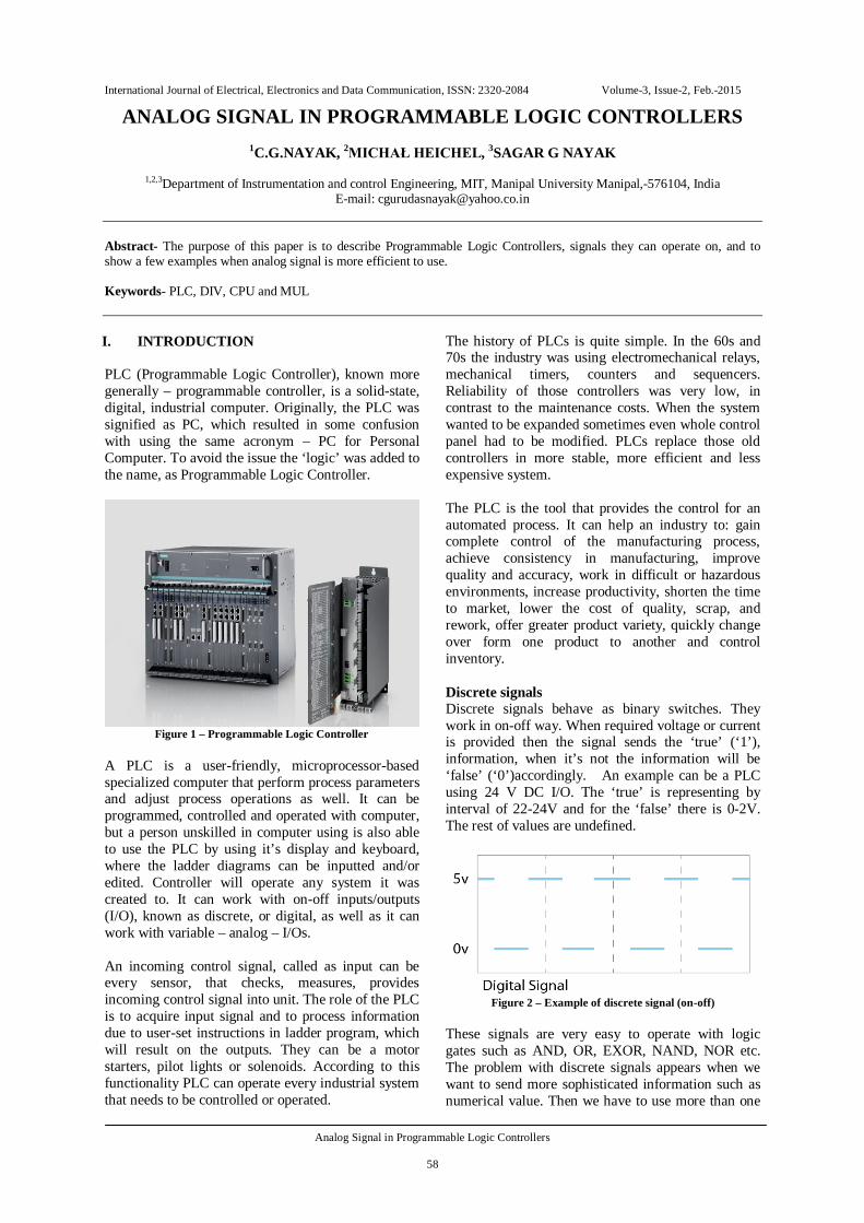
Figure 1 – Programmable Logic Controller
A PLC is a user-friendly, microprocessor-based specialized computer that perform process parameters and adjust process operations as well. It can be programmed, controlled and operated with computer, but a person unskilled in computer using is also able to use the PLC by using it’s display and keyboard, where the ladder diagrams can be inputted and/or edited. Controller will operate any system it was created to. It can work with on-off inputs/outputs (I/O), known as discrete, or digital, as well as it can work with variable – analog – I/Os. An incoming control signal, called as input can be every sensor, that checks, measures, provides incoming control signal into unit. The role of the PLC is to acquire input signal and to process information due to user-set instructions in ladder program, which will result on the outputs. They can be a motor starters, pilot lights or solenoids. According to this functionality PLC can operate every industrial system that needs to be controlled or operated.
The history of PLCs is quite simple. In the 60s and 70s the industry was using electromechanical relays, mechanical timers, counters and sequencers. Reliability of those controllers was very low, in contrast to the maintenance costs. When the system wanted to be expanded sometimes even whole control panel had to be modified. PLCs replace those old controllers in more stable, more efficient and less expensive system. The PLC is the tool that provides the control for an automated process. It can help an industry to: gain complete control of the manufacturing process, achieve consistency in manufacturing, improve quality and accuracy, work in difficult or hazardous environments, increase productivity, shorten the time to market, lower the cost of quality, scrap, and rework, offer greater product variety, quickly change over form one product to another and control inventory. Discrete signals Discrete signals behave as binary switches. They work in on-off way. When required voltage or current is provided then the signal sends the ‘true’ (‘1’), information, when it’s not the information will be ‘false’ (‘0’)accordingly. An example can be a PLC using 24 V DC I/O. The ‘true’ is representing by interval of 22-24V and for the ‘false’ there is 0-2V. The rest of values are undefined.
Figure 2 – Example of discrete signal (on-off)
These signals are very easy to operate with logic gates such as AND, OR, EXOR, NAND, NOR etc. The problem with discrete signals appears when we want to send more sophisticated information such as numerical value. Then we have to use more than one
International Journal of Electrical, Electronics and Data Communication, ISSN: 2320-2084 Volume-3, Issue-2, Feb.-2015
Analog Signal in Programmable Logic Controllers
59
input/output in PLC to send the information. Sometimes it’s really hard due to insufficient number of inputs/outputs in controller. Analog signals Analog signals non-step signals with a range of values between zero and full-scale. They can use voltage or current with a magnitude proportional to the value of the process signal
Figure 3 – Example of analog signal, as it is seen the signal is
continues with full range
Although most of the operations performed by a PLC are discrete I/O, in some situation a PLC is required to monitor or produce analog signals. For example if the PLC has to monitor the flow of oil in a pipe there is a turbine which produce on its output analog voltage signal. That kind of signal has to be connected into analog input (called also A/D input) . A/D Converter As PLC is an digital devices every performances are operated on discreet values. Every analog signal incoming or outgoing to/from PLC is converted. For incoming analog signals there is A/D (Analog-to-Digital) Converter. For outgoing signals, produced by PLC discrete signal is converted by D/A Converter which changes signals accordingly.
Figure 4 – Example of analog signal and its digital equivalent
With analog signal we can send exactly every information, with full range. Unfortunately, PLC as a digital device has to convert that signal into group of discrete signals it can perform on. A/D Converter divides the full-scale into parts which have concrete value in digital system. As PLCs typically use 16-bit signed binary processors, the integer values are limited between -32768 and +32767. Pressure,
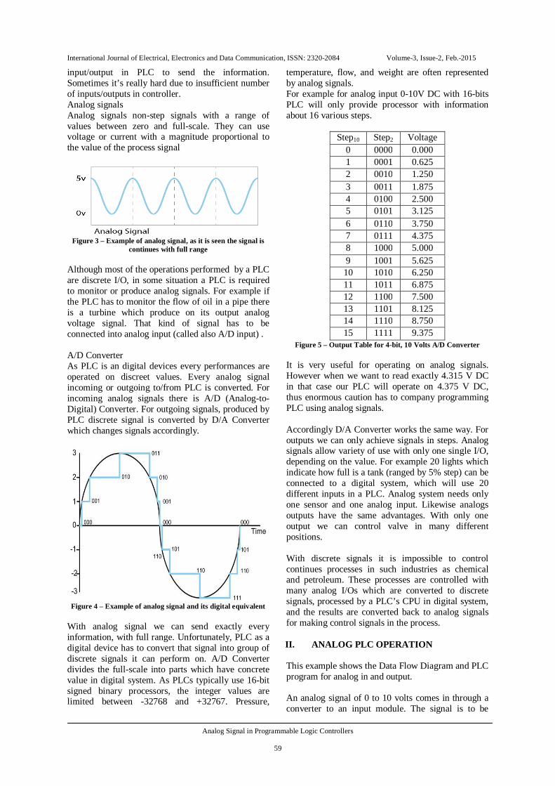
temperature, flow, and weight are often represented by analog signals. For example for analog input 0-10V DC with 16-bits PLC will only provide processor with information about 16 various steps.
Step10 Step2 Voltage 0 0000 0.000 1 0001 0.625 2 0010 1.250 3 0011 1.875 4 0100 2.500 5 0101 3.125 6 0110 3.750 7 0111 4.375 8 1000 5.000 9 1001 5.625 10 1010 6.250 11 1011 6.875 12 1100 7.500 13 1101 8.125 14 1110 8.750 15 1111 9.375
Figure 5 – Output Table for 4-bit, 10 Volts A/D Converter It is very useful for operating on analog signals. However when we want to read exactly 4.315 V DC in that case our PLC will operate on 4.375 V DC, thus enormous caution has to company programming PLC using analog signals. Accordingly D/A Converter works the same way. For outputs we can only achieve signals in steps. Analog signals allow variety of use with only one single I/O, depending on the value. For example 20 lights which indicate how full is a tank (ranged by 5% step) can be connected to a digital system, which will use 20 different inputs in a PLC. Analog system needs only one sensor and one analog input. Likewise analogs outputs have the same advantages. With only one output we can control valve in many different positions. With discrete signals it is impossible to control continues processes in such industries as chemical and petroleum. These processes are controlled with many analog I/Os which are converted to discrete signals, processed by a PLC’s CPU in digital system, and the results are converted back to analog signals for making control signals in the process. II. ANALOG PLC OPERATION This example shows the Data Flow Diagram and PLC program for analog in and output. An analog signal of 0 to 10 volts comes in through a converter to an input module. The signal is to be

International Journal of Electrical, Electronics and Data Communication, ISSN: 2320-2084 Volume-3, Issue-2, Feb.-2015
Analog Signal in Programmable Logic Controllers
60
scaled to 1/5 of its value by the CPU and then sent out through an output module.
Figure 6 – Data Flow Diagram (top) and PLC Program
(bottom) for the example of analog operation As IR0017 is the input and OR0024 the output, program when IN0016 is on, will operate whole scaling procedure. Operation on scaling input signal for proper output The linear input of 0 to 80 volts is to be scaled into the output as a linear 0 to 21 volts. To scale that signal we have to find proper mathematical equation. From linear proportions it is clear that we have to multiply the input by 21/80.
Figure 7 – Data Flow Diagram (top) and PLC Program (bottom) for the scaling input signal for proper output
Program, when IN0016 is enabled, will operate the process of multiply by 21 (and save the information to memory – MR0001) and then divide the result by
80. The other sequence is inefficient, because of limited memory of data in a PLC, as a digital device. When the value is first divided PLC will automatically round the value to the nearest possible for him, which with small quantities produce enormous defect on the result. Conditioning operation on more than one analog input There are two analog inputs A and B of 0 to 100 volts. If A exceeds 35 V, output F is to go on; if B exceeds 19 V, output G is to go on; if both exceed their listed numbers, output H is to go on; otherwise, no outputs are to be on.
Figure 8 – Data Flow Diagram (top) and PLC Program
(bottom) for the conditioning operation on more than one analog input
Those comparators placed in this example check if the first value is bigger than the second one. As input A and B, there are IR0017 and IR0018 used. For outputs F,G,H there are DO0005, DO006 and DO007 used accordingly. CONCLUSION A PLC is a user-friendly, microprocessor-based specialized computer that perform process parameters like addition, subtraction, multiplication and division
International Journal of Electrical, Electronics and Data Communication, ISSN: 2320-2084 Volume-3, Issue-2, Feb.-2015
Analog Signal in Programmable Logic Controllers
61
and adjust process operations as well. It can be programmed, controlled and operated with computer, REFERENCES:
[1]. Programmable Logic Controllers: Principles and Applications, Fifth Edition, 2003, John W. Webb, Ronald A. Reis, Prentice-Hall Inc.
[2]. Introduction to Programmable Logic Controllers, third edition, 2006, Gary Dunning, Cengage Learning India Private Limited
[3]. Programmable Logic Devices and Logic Controllers, 1996, Enrique Mandado, Jorge Marcos and Serafin A. Perez, Prentice Hall Europe
[4]. Digital System Design using Programmable Logic Devices, 2003, Parag K. Lala, BSP BS Publications
[5]. Programmable Logic Designer’s Guide, 1989, Roger C. Alford, Howard W. Sams & Company
[6]. Programmable Logic Controllers: Programming Methods and Applications, 2004, John R. Hackworth and Frederick D. Hackworth, Jr., Pearson Education, Inc.
ACKNOWLEDGEMENT We sincerely thank to Department of Instrumentation and Control Engineering at Manipal Institute of Technology, Manipal University, Manipal for providing required inputs.
1.Dr. C. Gurudas Nayak, received his B.E. in Instrumentation Technology in 1988 and M.S.
in Communication Engineering in the year 1996. PhD from Manipal University ,Manipal, in the year 2008. He has 23 years of Industrial /teaching experiences and published 60 papers in International, National Conferences and journals. He is currently working as an Associate Professor(ICE) in M.I.T. Manipal University, Manipal. His research interests include of Communication Networks and Mobile Telephone Systems.
2.Mr. Michał Heichel , (B.E) Automatic Control Engg. And Robotics, Poznan University of Technology, Poznan, Poland.
3.Mr. Sagar G Nayak , (BE) Electronices and Communications, NMAM Institute of Technology, Nitte, Karnataka.