anaerobic biotechnology for bioenergy production || anaerobic reactor configurations for bioenergy...
TRANSCRIPT

P1: SFK/UKS P2: SFK/UKS QC: SFK/UKS T1: SFK
BLBS011-Khanal 9780813823461 July 17, 2008 14:41
Chapter
5
Anaerobic Reactor Configurations
for Bioenergy Production
Samir Kumar Khanal
5.1 Background
Selection of the appropriate bioreactor type and configuration is particularly criticalto maximize metabolic, nonoxidative bioenergy production. A reactor appropriatefor bioenergy production may not be appropriate for waste treatment.
Biomass retention capacity is an important consideration when selecting a suit-able bioreactor because anaerobes grow slowly during metabolic generation ofmethane, hydrogen, ethanol, and butanol. It is frequently essential to select abioreactor configuration that decouples the hydraulic retention time (HRT) fromthe solids retention time (SRT). Such decoupling can maintain a significantly highSRT/HRT ratio and prevents washout of slow-growing anaerobes. Other consid-erations include feedstock types (solid, liquid, or gaseous), product inhibition,bioenergy recovery, and mass transfer limitations.
This chapter covers various approaches for decoupling HRT and SRT, classi-fication of different anaerobic bioreactor configurations with particular emphasison bioenergy generation, and design considerations for anaerobic bioreactors.
5.2 Strategies for Decoupling HRT and SRT
Decoupling SRT and HRT enhances the organic loading rate and enables reactorsize reductions. There are four approaches for decoupling SRT from HRT asoutlined in Table 5.1.
Decoupling is extremely difficult for high-solids feed streams. Such feed streamis often digested in a completely mixed reactor in which HRT = SRT. To maximizebioenergy production, therefore, a long detention time is needed. Pretreatment of
93Anaerobic Biotechnology for Bioenergy Production: Principles and Applications Samir Kumar Khanal © 2008 John Wiley & Sons, Inc. ISBN: 978-0-813-82346-1

P1: SFK/UKS P2: SFK/UKS QC: SFK/UKS T1: SFK
BLBS011-Khanal 9780813823461 July 17, 2008 14:41
94 Anaerobic Biotechnology for Bioenergy Production
Table 5.1. Different approaches to decouple HRT from SRT.
Approaches Biomass Retention Mechanisms Anaerobic Reactor Types
Biomass immobilizationin attached growthsystems
Anaerobes attach to the supportmedia (e.g., plastic, gravel, sand, andactivated carbon) to form biofilms
Anaerobic filter; rotating anaerobiccontactor; expanded/fluidized bedreactor
Granulation and flocformation
Anaerobic microorganismsagglomerate to form granules andflocs that settle well in the bioreactor
Upflow anaerobic sludge blanketreactor; static granular bed reactor;anaerobic-sequencing batchreactor; anaerobic baffled reactor
Biomass recycling Feed with high-suspended solids (e.g.,meat-packing waste and wood fiber)enables microorganisms to attach tosolids, thus forming settleable flocs,which are then recycled back to thereactor
Anaerobic contactreactor/Clarigester
Biomass retention Membrane integration into ananaerobic reactor retains biomass
Anaerobic membrane bioreactor
feed streams may reduce the detention time and enhance the bioenergy productionpotential as discussed in Chapter 11.
5.3 Classification of Anaerobic Bioreactors
Anaerobic reactors can be classified as low rate or high rate as shown in Fig. 5.1.Low-rate anaerobic reactors are unmixed. Temperature, SRT, and other envi-
ronmental conditions are not regulated. The organic loading rate is low in therange of 1–2 kg COD/m3·day. These reactor configurations are not suitable forbioenergy production. Some anaerobic ponds and lagoons, however, are coveredand are mixed to enhance biogas production and recovery.
High-rate anaerobic systems maintain a very high biomass level in the bioreactor.Environmental conditions are well maintained to optimize bioreactor performance.The organic loading rates vary from 5 to 30 kg COD/m3·day or even higher.High-rate anaerobic reactors are more appropriate for bioenergy production andare discussed in greater detail in the following section.
5.3.1 High-Rate Anaerobic Digester
5.3.1.1 General Description
High-rate anaerobic digesters are essentially a continuous stirred tank reactor(CSTR), operated under mesophilic or thermophilic conditions. Temperature-and acid-phase anaerobic digesters are other examples of high-rate anaerobic di-gesters, commonly employed for methane fermentation of high-solids (TS 1–6%)

P1: SFK/UKS P2: SFK/UKS QC: SFK/UKS T1: SFK
BLBS011-Khanal 9780813823461 July 17, 2008 14:41
Chapter 5 Anaerobic Reactor Configurations for Bioenergy Production 95
Low-rate anaerobic reactors High-rate anaerobic reactors
- Anaerobic pond
- Septic tank
- Imhoff tank
- Standard-rate
anaerobic digester
- High-rate anaerobic digester
- Anaerobic contact process
- Upflow anaerobic sludge blanket (UASB)
- Anaerobic-sequencing batch reactor (ASBR)
- Anaerobic filter (AF)
- Fluidized/expanded bed reactor
- Static granular bed reactor (SGBR)
- Anaerobic membrane reactor (AnMBR)
- Hybrid reactor
Suspended growth
Attached growth
Other
Fig. 5.1. Classification of anaerobic reactors.
wastes and residues, for example, municipal sludge, animal manure, and otherbiowastes. CSTR is also a common reactor configuration for hydrogen, ethanol,and butanol fermentation. Important considerations for anaerobic digestion ofmunicipal wastewater residuals are outlined in Table 5.2.
Table 5.2. Important considerations for anaerobic digester operation.
Component Remarks
Seed inocula Anaerobically digested sludge or biomass from a digester treating similarwaste streams
Start-up Feed rate at 20% of the design volatile solids loading capacity for the first20 days; gradual increase in the loading rate between 30 and 40 days; start-uptime 30–40 days (seed available), or 60–90 days (without seed available)
Important monitoringparameters
pH, alkalinity, volatile organic acids, and biogas production rate
HRT (or SRT) 15–30 days (high-rate digester); 30–60 days (low-rate digester)
Alkalinity 1,500–3,000 mg/L as CaCO3
VFA/ALK (alkalinity) ratio 0.1–0.2 for a healthy digester
Volatile solids loading rate 1.6–4.8 kg/m3·day (100–300 lb/1,000 ft3·day)
Biogas production rate 0.75–1.12 m3/kg VSremoved (12–18 ft3/lb VSremoved)
Biogas composition 55–70% CH4 and 25–35% CO2
Source: Adapted from Manual of Practice (MOP) # 16 1987.

P1: SFK/UKS P2: SFK/UKS QC: SFK/UKS T1: SFK
BLBS011-Khanal 9780813823461 July 17, 2008 14:41
96 Anaerobic Biotechnology for Bioenergy Production
5.3.1.2 Design Considerations
Although anaerobic digester design is typically based on an empirical approach,fundamental principles can be used to size a digester.
Fundamental Principles
For a suspended growth process (e.g., CSTR), the net growth of methanogens (r ′M)
can be written as follows:
r ′M = μmax,M
S
S + Ks,M
Xm − bM XM (5.1)
where r ′M is net growth rate of methanogens (ML−3T−1), S is concentration of
growth-limiting substrate (acetic acid) (ML−3),μmax,M is maximum specific growthrate of methanogens (T−1), X M is concentration of methanogens (ML−3), K s,M ishalf-velocity constant (ML−3), and bM is decay coefficient for methanogens (T−1).
The net specific growth rate (μ′M) can be obtained by dividing Eq. (5.1) by X M
as follows:
μ ′M = μmax,M
S
S +Ks,M
− bM (5.2)
The mass balance of digester methanogens as shown in Fig. 5.2 can be written asfollows:
dXM
dtV r = QX0 − QXM + r ′
MV r (5.3)
For the steady-state condition, d XM
dt= 0, when the methanogenic biomass (X M)
entering the digester = 0, Eq. (5.3) can be simplified to:
QXM = r ′MV r (5.4)
Vr
XM
S
Q
XM
S
Q
X0
S0
Fig. 5.2. Schematics of a completely mixed bioreactor.

P1: SFK/UKS P2: SFK/UKS QC: SFK/UKS T1: SFK
BLBS011-Khanal 9780813823461 July 17, 2008 14:41
Chapter 5 Anaerobic Reactor Configurations for Bioenergy Production 97
Combining Eqs (5.1) and (5.4), we have:
Q
V r
= 1
θc
= μmax,M
S
S+ Ks,M
− bM (5.5)
From Eqs (5.5) and (5.2), the solids retention time (θc) can be calculated as afunction of net specific growth rate. Knowing θc, the digester volume can be easilycalculated:
θc = 1
μ′M
(5.6)
Empirical Approach
Solids retention time (SRT): The optimum retention time needed for effective di-gestion can be assessed from laboratory and pilot-scale studies or by evaluationof existing operating plants based on the maximum bioenergy production as afunction of SRT. The retention time may vary from 15 to 30 days for mesophilicdigestion and from 5 to 15 days for thermophilic digestion. Digester size can beestimated by knowing the volume of waste and residues produced. It is importantto note that this approach does not take into consideration the waste characteristics.
Volatile solids (VS) loading rate: VS loading rate is the most commonly adoptedapproach for sizing an anaerobic digester. This approach does account for feedstockcharacteristics. The typical VS loading rate for mesophilic digestion is presentedin Table 5.2. For a thermophilic digester, the VS loading rate could be twice thatof mesophilic conditions.
Volatile solids reduction: VS destruction can be estimated using the followingempirical equation (Metcalf and Eddy 2003):
Vd = 13.7 ln(SRT) + 18.9 (5.7)
where Vd is volatile solids destruction (%) and SRT is solids retention time (day).In Eq. (5.7), the VS reduction correlates to SRT, which can then be used to
calculate the digester volume.
Example 5.1
A high-rate anaerobic digester is employed to stabilize primary and sec-
ondary sludge under mesophilic conditions. The primary sludge flow rate is
500 m3/day, with a total solids (TS) content of 5%, 68% of which is volatile.
The secondary sludge flow rate is 1,250 m3/day at a TS content of 1%, 75% of
which is volatile. Assume that the specific gravity of the primary and secondary
sludge is 1.02 and 1.01, respectively. The minimum SRT of the digester should

P1: SFK/UKS P2: SFK/UKS QC: SFK/UKS T1: SFK
BLBS011-Khanal 9780813823461 July 17, 2008 14:41
98 Anaerobic Biotechnology for Bioenergy Production
be 12 days, and the allowable VS loading rate is 2.5 kg VS/m3· day. How much
total VS load (in kg/day) is fed to the digester? Determine the digester volume
in m3.
Solution
(i) Find the mass of sludge produced:
Dry solids (kg/day), W = V × ρ × S× P
V = volume of sludge produced (m3/day)
ρ = density of water (kg/m3)
S = specific gravity of sludge
P = % of solids expressed in fraction
Primary sludge dry solid mass (kg/day) = 500 × 1,000 × 05 × 1.02 = 25,500
kg/day
Volatile solids in primary sludge (kg VS/day) = 25,500 × 0.68 = 17,340 kg
VS/day
Secondary sludge dry solid mass (kg/day) = 1,250 × 1,000 × .01 × 1.01 =12,625 kg/day
Volatile solids in secondary sludge (kg VS/day) = 12, 635 × 0.75 = 9,469 kg
VS/day
Total volatile solids = 17,340 + 9,469 = 26,809 kg VS/day
(ii) Size of digester
Based on SRT:
Total volume of sludge = 500 + 1, 250 = 1,750 m3/day
Given SRT = 12 days
Digester volume = 1, 750 × 12 = 21,000 m3
Based on volatile solids loading:
Total volatile solids = 26,809 kg VS/day
Given VS loading = 2.5 kg VS/m3· day
Digester volume = 26,809/2.5 = 10,724 m3
Note: Since the volume based on SRT is much higher than that based on VS
loading rate, SRT governs the design of digester. Thus by choosing the larger
volume, the possibility of biomass washout is minimized.
5.3.2 Anaerobic Contact Process
5.3.2.1 General Description
The anaerobic contact process (ACP) is essentially a CSTR with an external settlingtank to settle biomass, as illustrated in Fig. 5.3. The settled biomass is recycled backto maintain long SRT. The degassifier enables removal of biogas bubbles (CO2
and CH4) attached to the sludge particles; otherwise the sludge may float to thesurface. ACP is particularly useful for high-suspended solids waste streams (e.g.,

P1: SFK/UKS P2: SFK/UKS QC: SFK/UKS T1: SFK
BLBS011-Khanal 9780813823461 July 17, 2008 14:41
Chapter 5 Anaerobic Reactor Configurations for Bioenergy Production 99
Feed
Q
X0
S0
Biogas Biogas
V
X1,M
S1
Q2
X2,M
S2
Q3
X3,M
Completely mixed reactor
Degassifier
Settling tank
Recycled sludge
Waste sludge
Effluent
Fig. 5.3. Schematics of anaerobic contact process.
meat-packing waste, wood fiber). Microorganisms are able to attach themselves toparticulates, forming settleable solids in the process.
Typical reactor biomass concentrations are 4–6 g/L, with maximum concentra-tions as high as 25–30 g/L, depending on the settleability of sludge. The loadingrate ranges from 0.5 to 10 kg COD/m3·day. The required SRT can be maintainedby controlling the recycle rate similarly to an activated sludge process.
5.3.2.2 Design Considerations
Since ACP is a suspended growth process, the design approach is very similar tothat described in Section 5.3.1.2, except that biomass is allowed to settle and isrecycled in the process. Therefore, the mass balance of ACP methanogens, as shownin Fig. 5.3, includes both settled effluent and waste sludge in outflow streams.
The mass balance for ACP methane producers is given by (Henze et al. 2002):
μ′M XMVr = Q2 X2,M + Q3 X3,M (5.8)
From Eqs (5.6) and (5.8), the anaerobic reactor volume is given by:
Vr = Q2 X2,M + Q3 X3,M
XM
θc (5.9)
In Eq. (5.9), θc can be obtained from Fig. 5.4, depending on operating temper-ature; X M is a parameter that can be selected based on the process; and the term

P1: SFK/UKS P2: SFK/UKS QC: SFK/UKS T1: SFK
BLBS011-Khanal 9780813823461 July 17, 2008 14:41
100 Anaerobic Biotechnology for Bioenergy Production
010 20 30 40 50 60 70
Temperature °C
10
20
30
40
50
60
70
80
Slu
dge
age
(day
s)
Fig. 5.4. Needed solids retention time at different temperature for anaerobic processes.
Source: Henze et al. (2002). Reprinted with permission.
(Q2 X 2,M+ Q3 X 3,M) is the biomass (sludge) production rate (Px), which can becalculated using the following expression:
Px = Yobs Q (S0 − S2)
(1 + bMθc)
(5.10)
where Yobs is observed yield in kg biomass-COD/kg COD (0.05–0.10 biomass-COD/kg CODremoved).
5.3.3 Anaerobic Filter
The first published report describing the application of an anaerobic filter (biofilm)for wastewater treatment was reported by Young and McCarty (1969). The au-thors evaluated the suitability of an anaerobic filter to treat soluble organic feed.Depending on feeding mode, an anaerobic filter can be classified as an upflowanaerobic filter (UAF), a downflow anaerobic filter (DAF), or a multifed anaerobicfilter (MFAF) (Fig. 5.5). Recirculation is generally not recommended for maxi-mum bioenergy recovery. A detailed discussion of each filter type is presented inthe following sections.

P1: SFK/UKS P2: SFK/UKS QC: SFK/UKS T1: SFK
BLBS011-Khanal 9780813823461 July 17, 2008 14:41
Chapter 5 Anaerobic Reactor Configurations for Bioenergy Production 101
Feedin
Biogas
Effluent out
Excesssludge
Feedin
Biogas
Effluent out
Excesssludge
Biogas
Effluent out
Excesssludge
Feedin
(a) (b) (c)
Fig. 5.5. Schematic diagram of anaerobic filter: (a) upflow anaerobic filter, (b) downflow
anaerobic filter, and (c) multifed anaerobic filter.
5.3.3.1 Upflow Anaerobic Filter
In a UAF, wastewater is distributed across the bottom and the flow proceeds upwardthrough a bed of rocks or plastic media. The entire filter bed is submerged.
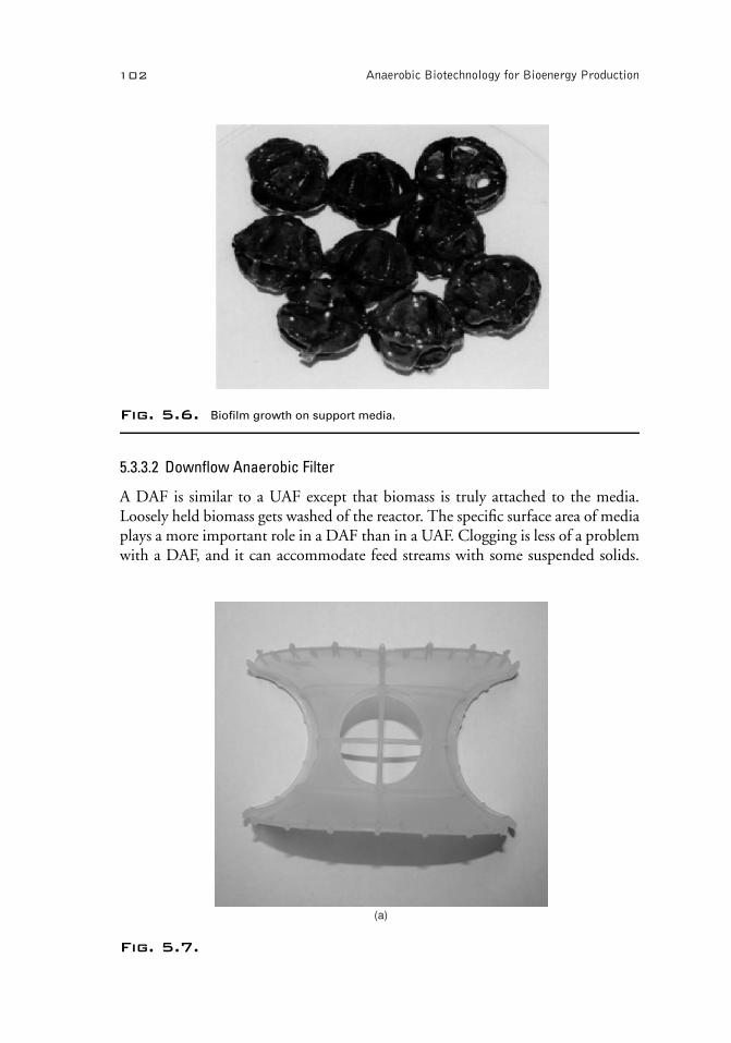
Although UAF is a fixed-film reactor, a significant portion of the biomass remainsentrapped within the interstices between the media. The nonattached biomassforms bigger floc and eventually takes a granular shape due to the rolling ac-tion of rising gas bubbles. Thus, nonattached biomass contributes significantlyto biological activity. Biofilm growth on support media in a UAF is shown inFig. 5.6.
Originally, rocks were employed as packing media in anaerobic filters. But dueto a very low void volume (40–50%), serious clogging problem occurred. In thepresent day, medium is often synthetic plastic or ceramic tiles of different config-urations. The void volume of plastic media ranges from 80 to 95% and provides ahigh specific surface area, typically 100 m2/m3 or higher which enhances biofilmgrowth. Figure 5.7 shows plastic media of different configurations.
Since an anaerobic filter retains a large amount of biomass, a long SRT canbe maintained regardless of HRT. Typically, HRT varies from 0.5 to 4 days andthe loading rate varies from 5 to 15 kg COD/m3 · day. Wasting of biomass maybe needed periodically to minimize clogging and short-circuiting. Hydrodynamicconditions play an important role in biomass retention within the void space. Theflow regime is often quasi-plug flow.
P1: SFK/UKS P2: SFK/UKS QC: SFK/UKS T1: SFK
BLBS011-Khanal 9780813823461 July 17, 2008 14:41
102 Anaerobic Biotechnology for Bioenergy Production
Fig. 5.6. Biofilm growth on support media.
5.3.3.2 Downflow Anaerobic Filter
A DAF is similar to a UAF except that biomass is truly attached to the media.Loosely held biomass gets washed of the reactor. The specific surface area of mediaplays a more important role in a DAF than in a UAF. Clogging is less of a problemwith a DAF, and it can accommodate feed streams with some suspended solids.
(a)
Fig. 5.7.

P1: SFK/UKS P2: SFK/UKS QC: SFK/UKS T1: SFK
BLBS011-Khanal 9780813823461 July 17, 2008 14:41
Chapter 5 Anaerobic Reactor Configurations for Bioenergy Production 103
(b)
(c)
Fig. 5.7. Plastic media of different configurations.
Although a DAF has a low biomass inventory, the specific activity of its biomassis relatively high. A DAF is more suitable for treating sulfate-rich wastewater, inwhich sulfate reduction occurs in the upper zone and methanogenesis in the lowerzone. This physical separation of two microbial communities reduces the inhibitoryeffect of sulfide on methanogens.

P1: SFK/UKS P2: SFK/UKS QC: SFK/UKS T1: SFK
BLBS011-Khanal 9780813823461 July 17, 2008 14:41
104 Anaerobic Biotechnology for Bioenergy Production
5.3.3.3 Multifed Anaerobic Filter
In an MFAF, the feed enters the bioreactor through several points along filter depth.The merits of this strategy include (Punal et al. 1998) the following:
� Homogenous biomass distribution throughout the bed, unlike the stratificationof hydrolytic, acidogenic, and methanogenic groups in a single-fed system.� Maintenance of a completely mixed regime throughout the reactor, thus prevent-ing short-circuiting and accumulation of volatile fatty acids (VFAs).� Uniform substrate concentration throughout the reactor, which prevents heavygrowth of biomass in the bottom of the reactor, thereby minimizing clogging ofthe filter bed.� Effective utilization of the whole filter bed, with a working volume of 87%,compared to only 65% for a filter with a single feed point.
5.3.3.4 Design Considerations
Deriving a mathematical expression for the design of an anaerobic filter in-volves many variables. Importantly, a significant portion of the biomass remainsunattached within the void spaces. An empirical approach based on the volumetricorganic loading rate is the most common method of designing an anaerobic filterand is given by:
VOLR = C0 · Q
Vr
(5.11)
where VOLR is volumetric organic loading rate (kg COD/m3·day), C0 is feedCOD concentration (kg/m3 or mg/L),Q is feed flow rate (m3/day), andVr is biore-actor volume (m3).
C0 and Q are known parameters for a given feed stream. VOLR is obtained basedon laboratory and pilot-scale studies that examine maximum bioenergy production(instead of removal efficiency) as a function of loading rate. The reactor volume canbe easily determined using Eq. (5.11). If the bioreactor volume does not accountfor void ratio (ε), the total working volume (VT) should be determined as follows:
VT = Vr
ε(5.12)
Example 5.2
A UAF has been employed to produce biomethane from distillery slops at 35◦C.
The influent flow rate is 1,000 m3/day and soluble chemical oxygen demand
(SCOD) concentration is 25 g/L. Based on pilot testing, maximum biogas pro-
duction was obtained at VOLR of 15 kg/m3·day.

P1: SFK/UKS P2: SFK/UKS QC: SFK/UKS T1: SFK
BLBS011-Khanal 9780813823461 July 17, 2008 14:41
Chapter 5 Anaerobic Reactor Configurations for Bioenergy Production 105
(i) Design an anaerobic filter process using spherical polypropylene support
media. The porosity of the bioreactor with the packing media is 85%.
(ii) Calculate the maximum CH4 generation rate in m3/day. What would be the
biogas generation rate at 80% COD removal efficiency where 12% of the
removed COD is utilized for biomass synthesis and the biogas contains
70% CH4 by volume?
(iii) What is the total energy that could be generated from CH4 in kWh?
(i) Anaerobic filter design
From Eq. (5.11), the working volume of anaerobic filter is:
Vr = 25 kg/m3 × 1,000 m3/day
15 kg/m3/day= 1,667 m3
(Note: Assume that the volume accounts for space occupied by packing
media.)
Provide four anaerobic filters of 6-m diameter and 15-m height.
(ii) Maximum CH4 generation and biogas production
Maximum COD removed = 25 kg COD/m3 × 1,000 m3/day = 25,000 kg/day
At STP, 1 kg COD produces 0.35 m3 of CH4
Total CH4 production at STP = 0.35 × 25,000 = 8,750 m3/day
Maximum CH4 production at 35◦C = 8,750 × ((273 + 35)/273) = 9,872
m3/day
COD removed at 80% efficiency = 0.80 × 25,000 kg/day = 20,000 kg/day
Since, 12% of removed COD is utilized in biomass synthesis, the COD
available for CH4 production = 0.88 × 20,000 = 17,600 kg/day
At STP, CH4 production from the remaining COD = 0.35 × 17,600 = 6,160
m3/day
At 35◦C, CH4 production = 6,160 × (273 + 35)/273 = 6,950 m3/day
Biogas production with 70% methane = 6,950/0.7 = 9,929 m3/day
(iii) Total energy generated from CH4
1 kg COD generates = 1.16 kWh (see Chapter 1)
Available COD for methane generation = 17,600 kg/day
Total energy generation = 17,600 × 1.16 = 20,416 Kwh/day
5.3.4 Upflow Anaerobic Sludge Blanket
5.3.4.1 General Description
Upflow anaerobic sludge blanket (UASB) was developed in the 1970s by Lettingaand coworkers in the Netherlands to treat sugar-rich soluble wastewater (Lettingaet al. 1980). UASB is essentially a suspended growth system in which properhydraulic and organic loading conditions are maintained in order to facilitate theformation of dense biomass aggregates known as granules. The diameter of thegranules varies from 1 to 3 mm. Granules have superior settling characteristics

P1: SFK/UKS P2: SFK/UKS QC: SFK/UKS T1: SFK
BLBS011-Khanal 9780813823461 July 17, 2008 14:41
106 Anaerobic Biotechnology for Bioenergy Production
(∼60 m/h). A UASB reactor is operated at a superficial upflow velocity less than2 m/h. This way SRT and HRT can be easily decoupled. Thus, an extremely longSRT of 200 days can be achieved at HRT as low as 6 h (Hulshoff Pol et al. 2004).Due to its ability to absorb extremely high VOLR (up to 50 kg COD/m3·day),UASB is ideally suited for biomethane production from a high-strength solublefeed stream. Detailed discussion on the theory of granulation is presented elsewhere(Hulshoff Pol et al. 2004).
5.3.4.2 Working Principle of UASB Reactor
Feed is uniformly distributed through a specially designed distributor at the bottomof the reactor. The active anaerobic granules in the reaction zone metabolize theorganic matter to biogas. Large and dense granules remain suspended within thesludge bed due to superficial upflow velocity and rising biogas bubbles. Granuleswith entrapped gas enter into the gas–solid separator (GSS), where the gas bubblesget detached as they hit the inclined wall (Fig. 5.8). The granules then slide backinto the reactor. The biogas is collected through a gas collection system. Theliquid and smaller-size granules enter the settling zone, which is designed in such away that the superficial upflow velocity decreases significantly as the liquid movesupward (due to a gradual increase in surface area). This facilitates settling of smalland light granules back into the reactor. The effluent is collected in a series of weirsplaced at the top of the reactor.
Settlingzone
Gas–solidseparator
Feed
Biogas
Baffle
Sludge bed
Weir for effluent
collection
Rising gas bubble
Feed distributor
Fig. 5.8. Schematic diagram of upflow anaerobic sludge blanket reactor.

P1: SFK/UKS P2: SFK/UKS QC: SFK/UKS T1: SFK
BLBS011-Khanal 9780813823461 July 17, 2008 14:41
Chapter 5 Anaerobic Reactor Configurations for Bioenergy Production 107
5.3.4.3 Design Considerations
To maximize bioenergy production from high-strength feed streams, the UASBreactor design should be based on the maximum allowable VOLR. Either an em-pirical or theoretical approach could be used to determine VOLR. The empiricalapproach employs pilot-scale testing to obtain the optimum VOLR correspondingto maximum methane production, as illustrated in earlier section. The theoreticalapproach based on specific sludge activity (or specific substrate utilization rate) (U )is discussed here (Lettinga and Hulshoff Pol 1992).
VOLR = Xo fp foSFU (5.13)
where X o is biomass concentration in the reactor (kg/m3 or mg/L), fp is contactfactor between sludge particles and feed (unitless), fo is contact factor betweensubstrate and active biomass (unitless), andSF is safety factor (unitless).
Specific sludge activity (U ) is given by:
U = kmaxS
Ks + S(5.14)
where kmax is maximum specific substrate utilization rate (kg COD/kgbiomass·day), S is concentration of growth-limiting substrate (kg/m3 or mg/L),and K s is half-velocity constant (kg/m3 or mg/L).
kmax can also be expressed as μmax/Yobs, whereYobs is observed yield coefficient.From Eqs (5.13) and (5.14), we have the following:
VOLR = Xo fp foSF
kmaxS
Ks + S(5.15)
In the above equation, the desired X o can be maintained by controlling the sludgewastage rate; S is the effluent SCOD concentration that can be set; and kmax andK s are the biokinetic parameters of sludge (granules) that can be obtained fromliterature or determined experimentally. SF can be chosen based on the designengineer’s experience. The “f ” factor is governed by the effectiveness of the feeddistribution factor. For VOLR exceeding 5–10 kg COD/m3·day, the f factor ap-proaches unity (Lettinga and Hulshoff Pol 1992). Furthermore, mixing associatedwith biogas production at higher VOLR also facilitates better contact between feedand the biomass.
It is important that the superficial velocity (va) should be maintained below thewashout point of granules. The superficial velocity can be calculated by:
va = H
θ(5.16)
where H is reactor height (m) and θ is hydraulic retention time (h).

P1: SFK/UKS P2: SFK/UKS QC: SFK/UKS T1: SFK
BLBS011-Khanal 9780813823461 July 17, 2008 14:41
108 Anaerobic Biotechnology for Bioenergy Production
Biogas
Activevolume
Gravel underdrain
Feed
Granules
Effluent
Fig. 5.9. Static granular bed reactor.
A velocity of 5 m/h is recommended for successful operation of a UASB reactor.A higher velocity may also be possible, especially if the granules are large anddense. In a UASB reactor, where a superficial velocity >6 m/h is applied is knownas an expanded granular sludge bed (EGSB). The higher velocity helps expand orpartially fluidize the sludge bed. Since EGSB was developed to treat low-strengthwastewater and wastewater with some particulate matter (Kato et al. 1994), itspotential for bioenergy production is limited and is not discussed further.
5.3.5 Static Granular Bed Reactor
Static granular bed reactor (SGBR) is a patented process developed at Iowa StateUniversity by Ellis and Mach (Mach 2000). It also employs granules similar to aUASB reactor. SGBR, however, is operated in downflow mode without recircula-tion as shown in Fig. 5.9. It does not require an elaborate feed distribution systemand solid–gas separator. One major concern is head loss due to solids buildup forfeed with suspended solids (>2,000 mg/L). SGBR, therefore, is mainly suitablefor low-particulate feed streams. Several pilot-scale studies are currently being con-ducted to examine its applicability for bioenergy production from high-strengthfeed streams. For scale up from pilot-scale studies, design parameters such as HRT,VOLR, and head loss of the SGBR system need to be examined.
5.3.6 Anaerobic Sequential Batch Reactor
5.3.6.1 General Description
The anaerobic sequential batch reactor (ASBR) was developed by Dague andcoworkers at Iowa State University in the early 1990s (Dague et al. 1992). The

P1: SFK/UKS P2: SFK/UKS QC: SFK/UKS T1: SFK
BLBS011-Khanal 9780813823461 July 17, 2008 14:41
Chapter 5 Anaerobic Reactor Configurations for Bioenergy Production 109
Settle Decant Feed React
Settled biomass
Supernatant
Decantports
Biogas Recycle
Effluent Feed
Biogas
Fig. 5.10. Operating steps for the anaerobic-sequencing batch reactor.
Source: Dague et al. (1992). Reprinted with permission.
ASBR system was developed as a high-rate anaerobic reactor to treat high-strengthand medium solids content feeds (TS: 1–4%). Because of sequential operation, asingle reactor can be used as a reaction vessel and as a settling tank, achieving highbiomass levels in the reactor regardless of HRT. The ASBR process retains biomassdue to bioflocculation followed by biogranulation similar to a UASB reactor. Thefirst full-scale ASBR plant was built in 1997 at Excel Corporation in Ottumwa,Iowa, USA, to treat meat-packing plant wastewater. The ASBR process is highlysuitable for bioenergy production from animal manure and other biowastes withmedium TS contents.
5.3.6.2 Working Principle of ASBR
As illustrated in Fig. 5.10, the ASBR operation includes four steps: settle, decant,feed, and react. The sequencing frequency and the feed volume processed witheach sequence determine the hydraulic loading (HRT) and the strength of thewaste establishes the VOLR. The reactor biomass concentration is an importantvariable affecting biomass settleability. Initial food-to-microorganism (F/M) ratioaffects bioflocculation and biochemical reactions.
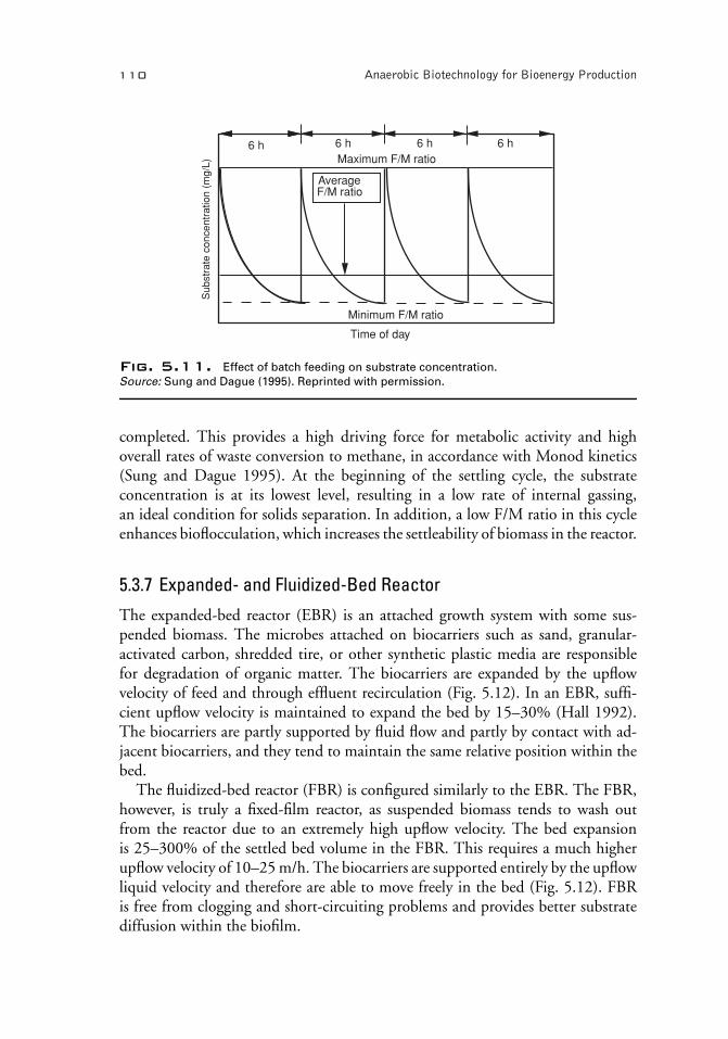
In a continuously fed, completely mixed reactor operating at steady state, thesubstrate concentration surrounding the microorganisms is constant. In a batch-fedreactor, the substrate concentration is high immediately after feeding and continu-ously declines until the reactor is fed again, as illustrated in Fig. 5.11. The substrateconcentration just prior to feeding in the batch-fed system is lower than that at anytime in the continuously fed system. Thus, the batch-fed system achieves a more ef-ficient biomass flocculation and solids separation than the continuously fed system.
The phenomenon described is one of the key characteristics of the ASBR process.The other key characteristic is that, at any given biomass concentration in thereactor, the F/M ratio is at its highest level immediately after the feed cycle is
P1: SFK/UKS P2: SFK/UKS QC: SFK/UKS T1: SFK
BLBS011-Khanal 9780813823461 July 17, 2008 14:41
110 Anaerobic Biotechnology for Bioenergy Production
Maximum F/M ratio
Minimum F/M ratio
Time of day
6 h 6 h 6 h 6 h
Average F/M ratio
Sub
stra
te c
once
ntra
tion
(mg/
L)
Fig. 5.11. Effect of batch feeding on substrate concentration.
Source: Sung and Dague (1995). Reprinted with permission.
completed. This provides a high driving force for metabolic activity and highoverall rates of waste conversion to methane, in accordance with Monod kinetics(Sung and Dague 1995). At the beginning of the settling cycle, the substrateconcentration is at its lowest level, resulting in a low rate of internal gassing,an ideal condition for solids separation. In addition, a low F/M ratio in this cycleenhances bioflocculation, which increases the settleability of biomass in the reactor.
5.3.7 Expanded- and Fluidized-Bed Reactor
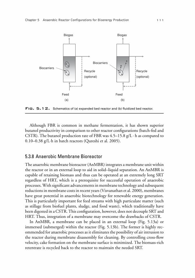
The expanded-bed reactor (EBR) is an attached growth system with some sus-pended biomass. The microbes attached on biocarriers such as sand, granular-activated carbon, shredded tire, or other synthetic plastic media are responsiblefor degradation of organic matter. The biocarriers are expanded by the upflowvelocity of feed and through effluent recirculation (Fig. 5.12). In an EBR, suffi-cient upflow velocity is maintained to expand the bed by 15–30% (Hall 1992).The biocarriers are partly supported by fluid flow and partly by contact with ad-jacent biocarriers, and they tend to maintain the same relative position within thebed.
The fluidized-bed reactor (FBR) is configured similarly to the EBR. The FBR,however, is truly a fixed-film reactor, as suspended biomass tends to wash outfrom the reactor due to an extremely high upflow velocity. The bed expansionis 25–300% of the settled bed volume in the FBR. This requires a much higherupflow velocity of 10–25 m/h. The biocarriers are supported entirely by the upflowliquid velocity and therefore are able to move freely in the bed (Fig. 5.12). FBRis free from clogging and short-circuiting problems and provides better substratediffusion within the biofilm.
P1: SFK/UKS P2: SFK/UKS QC: SFK/UKS T1: SFK
BLBS011-Khanal 9780813823461 July 17, 2008 14:41
Chapter 5 Anaerobic Reactor Configurations for Bioenergy Production 111
Biogas
Biocarriers
Feed
Recycle
(optional)
Biogas
Biocarriers
Feed
Recycle
(optional)
(a) (b)
Fig. 5.12. Schematics of (a) expanded bed reactor and (b) fluidized bed reactor.
Although FBR is common in methane fermentation, it has shown superiorbutanol productivity in comparison to other reactor configurations (batch-fed andCSTR). The butanol production rate of FBR was 4.5–15.8 g/L · h as compared to0.10–0.38 g/L·h in batch reactors (Qureshi et al. 2005).
5.3.8 Anaerobic Membrane Bioreactor
The anaerobic membrane bioreactor (AnMBR) integrates a membrane unit withinthe reactor or in an external loop to aid in solid–liquid separation. An AnMBR iscapable of retaining biomass and thus can be operated at an extremely long SRTregardless of HRT, which is a prerequisite for successful operation of anaerobicprocesses. With significant advancements in membrane technology and subsequentreductions in membrane costs in recent years (Visvanathan et al. 2000), membraneshave great potential in anaerobic biotechnology for renewable energy generation.This is particularly important for feed streams with high particulate matter (suchas stillage from biofuel plants, sludge, and food waste), which traditionally havebeen digested in a CSTR. This configuration, however, does not decouple SRT andHRT. Thus, integration of a membrane may overcome the drawbacks of CSTR.
In AnMBR, a membrane can be placed in an external loop (Fig. 5.13a) orimmersed (submerged) within the reactor (Fig. 5.13b). The former is highly rec-ommended for anaerobic processes as it eliminates the possibility of air intrusion tothe reactor during membrane disassembly for cleaning. By controlling cross-flowvelocity, cake formation on the membrane surface is minimized. The biomass-richretentrate is recycled back to the reactor to maintain the needed SRT.

P1: SFK/UKS P2: SFK/UKS QC: SFK/UKS T1: SFK
BLBS011-Khanal 9780813823461 July 17, 2008 14:41
112 Anaerobic Biotechnology for Bioenergy Production
Feed
Permeate pump
Biogas
Excess biomass
Biomass recycling
Permeate
Cross-flowmembrane
module
Feed Permeate pump
Biogas
Excess biomass
Permeate
MembranemoduleBiogas
recirculation pump
Gas diffuser
(a) (b)
Fig. 5.13. Anaerobic membrane bioreactors: (a) membrane in an external loop and
(b) membrane immersed in the reactor.
Coupling the membrane to the anaerobic reactor prevents the washout of slow-growing microorganisms, especially methanogens. Factors affecting membraneperformance include membrane types and modules, transmembrane pressure,cross-flow velocity, feed characteristics, biomass levels, and membrane fouling.
5.4 Membrane Technology for Syngas Fermentation to Ethanol
Ethanol can be produced from fermentation of sugar-rich feedstocks. Anotherapproach is through fermentation of gaseous feedstock known as synthesis gas(syngas), which comprises CO and H2. One major challenge with syngas fermen-tation is the gas–liquid mass transfer of CO and H2 due to their poor solubilityin an aqueous phase. Different approaches such as high gas and liquid flow rates,large specific gas–liquid interfacial areas, and use of increased pressure or solventshave been examined to enhance the efficiency of gas solubility in liquid phase(Lee and Rittmann 2002). However, the shortcoming of these methods are loss ofgaseous feedstock as waste bubbles and difficulties in process control along withunpredictable gas–liquid contact (Ahmed et al. 2004).
The use of hydrophobic hollow-fiber membrane (HFM) can improve transfer ofsyngas to the close proximity of biofilm (Fig. 5.14). In the HFM, syngas is diffusedthrough the walls of membranes without loss of gas through bubble formation.Besides, this approach offers great flexibility in process control as the gas partialpressure in the membrane lumen and the surface area available for gas transfer can bemanipulated independently (Lee and Rittmann 2002). The use of HFM in syngasfermentation has not been reported at the time of writing this chapter. The otherapplications of HFM, where gas–liquid mass transfer is critical, are discussed here.

P1: SFK/UKS P2: SFK/UKS QC: SFK/UKS T1: SFK
BLBS011-Khanal 9780813823461 July 17, 2008 14:41
Chapter 5 Anaerobic Reactor Configurations for Bioenergy Production 113
Syn
gas
Gas
Gas
Gas
Gas
Gas
Gas
Biofilm
Microporous fiber
Bundle of hollow fibers
Gas manifold
Fig. 5.14. Hollow-fiber membrane system for syngas fermentation.
Voss et al. (1999) employed polydimethylsiloxane (PDMS) coated polypropy-lene membrane for oxygen transfer. The gas pressure inside the non-porous-coatedfibers increased up to 60 psi without bubble formation. Mitsubishi Rayon Corpo-ration developed composite membranes that contain a nonporous, gas-permeablepolyurethane layer (1 mm thick) embedded into the membrane wall as illustrated inFig. 5.15. The polyurethane layer allows bubbleless operation at very high oxygenfeed pressures similar to PDMS-coated membranes with a 100% oxygen transferefficiency (Ahmed et al. 2004).
A hollow-fiber membrane bioreactor was developed to use hydrogen gas asan electron donor (Lee and Rittmann 2002; Nerenberg and Rittmann 2004). Abundle of sealed-end hollow fibers were housed in a hydrogen gas dissolutionunit, and biofilm was developed on the surface of the hollow fiber. The bioreactorallowed 100% hydrogen transfer into the biofilm and achieved effective removal ofnitrate, perchlorate, bromate, chlorate, chlorite, chromate, selenate, selenite, anddichloromethane.
The feasibility study of using HFM for syngas fermentation is currently beingevaluated at the author’s laboratory at the University of Hawaii.
1-mm urethane layer
Fiber lumen
Inner microporous polyethylene
Outer microporous polyethylene
Fig. 5.15. Cross section of a polyethylene hollow fiber composite membrane with 1-mm
polyurethane layer in the membrane wall.
Source: Ahmed et al. (2004). Reprinted with permission.

P1: SFK/UKS P2: SFK/UKS QC: SFK/UKS T1: SFK
BLBS011-Khanal 9780813823461 July 17, 2008 14:41
114 Anaerobic Biotechnology for Bioenergy Production
References
Ahmed, T., Semmens, M. J., and Voss, M. A. 2004. Oxygen transfer characteristics of hollow-fiber,
composite membranes. Adv. Environ. Res. 8:637–646.
Dague, R. R., Habben, C. E., and Pidaparti, S. R. 1992. Intial studies on anaerobic sequential batch
reactor. Water. Sci. Technol. 26(9–11):2429–2432.
Hall, E. R. 1992. Anaerobic treatment of wastewaters in suspended growth and fixed film processes. In
Design of Anaerobic Processes for the Treatment of Industrial and Municipal Wastes, edited by J. F. Malina,
Jr, and F. G. Pohland, pp. 1–40. Technomic Publishing Co. Inc., Lancaster, USA.
Henze, M., Harremoes, P., Jansen, J. C., and Arvin, E. 2002. Wastewater Treatment: Biological and Chemical
Processes, 3rd edn, pp. 303–304. Springer-Verlag., Berlin, Germany.
Hulshoff Pol, L. W., Lopes, C. I. S., Lettinga, G., and Lens, L. N. P. 2004. Anaerobic sludge granulation.
Water. Res. 38:1376–1389.
Kato, M. T., Field, J. A., Versteeg, P., and Lettinga, G. 1994. Feasibility of expanded granular sludge bed
reactors for the anaerobic treatment of low-strength soluble wastewaters. Biotechnol. Bioeng. 44:469–
479.
Lee, K.-C., and Rittmann, B. E. 2002. Applying a novel autohydrogenotrophic hollow-fiber membrane
biofilm reactor for denitrification of drinking water. Water Res. 36:2040–2052.
Lettinga. G., Velsen, A. F. M., Hobma, S. W., de Zeeuw, W., and Klapwijk, A. 1980. Use of the upflow
sludge blanket (USB) reactor concept for biological wastewater treatment, especially for anaerobic
treatment. Biotechn. Bioeng. XXII:699–734.
Lettinga, L., and Hulshoff Pol, L. W. 1992. UASB design for various types of wastewaters. In Design of
Anaerobic Processes for the Treatment of Industrial and Municipal Wastes, edited by J. F. Malina, Jr., and
F. G. Pohland, pp. 119–145. Technomic Publishing Co. Inc., Lancaster, USA.
Mach, K. F. 2000. Development of Static Granular Bed Reactor. M.S. thesis, Iowa State University, Ames,
IA, USA.
Manual of Practice (MOP) # 16 1987. Anaerobic Sludge Digestion, 2nd edn. Water Pollution Control
Federation, Alexandria, VA, USA.
Metcalf and Eddy 2003. Wastewater Engineering : Treatment and Reuse, 4th edn. McGraw-Hill Companies,
Inc., New York, USA.
Nerenberg, R., and Rittmann, B. E. 2004. Hydrogen-based, hollow-fiber membrane biofilm reactor for
reduction of perchlorate and other oxidized contamitants. Water Sci. Technol. 49(11–12):223–230.
Punal, A., Menal, R., and Lema, J. M. 1998. Multi-fed upflow anaerobic filter: Development and features.
J . Environ. Eng. ASCE 124(12):1188–1192.
Qureshi, N., Annous,B. A., Ezeji, T. C., Karcher, P., and Maddox, I. S. 2005. Biofilm reactors for
industrial bioconversion processes: Employing potential of enhanced reaction rates. Microb. Cell Fact.
4:24. Available at: http://www.pubmedcentral.nih.gov/picrender.fcgi?artid=1236956&blobtype=pdf
(accessed December 16, 2007).
Sung, S., and Dague, R. R. 1995. Laboratory studies on the anaerobic sequencing batch reactor. Water
Environ. Res. 67(3):294–301.
Visvanathan, C., Ben Aim, R., and Parameshwaran, K. 2000. Membrane separation bioreactors for
wastewater treatment. Crit. Rev. Environ. Sci. Technol. 30(1):1–48.
Voss, M. A., Ahmed, T., and Semmens, M. J. 1999. Long term performance of parallel flow bubbleless
hollow fiber membrane aerator. Water Environ. Res. 71(1):23–30.
Young, J. C., and McCarty, P. L. 1969. The anaerobic filter for waste treatment. J. WPCF 41(5):R160–
R173.