an5516-06 optical line terminal...
TRANSCRIPT

AN5516-06
Optical Line Terminal Equipment
Hardware Description
Version: A
Code: MN000000814
=\;(/FiberHome
May 2011

I
Preface
Related Documentation
Document Description
AN5516-06 Optical Line
Terminal Equipment
Documentation Guide
Introduces the retrieval method, contents, releasing,
reading approach, and suggestion feedback method for
the complete manual set for the AN5516-06.
AN5516-06 Optical Line
Terminal Equipment Product
Description
Introduces the AN5516-06's network location, functional
features, hardware structure, FTTx application model,
equipment configuration, network management system
and technical specifications. It is the foundation of the
complete manual set. The other manuals extend and
enrich the concepts introduced in the Product Description.
AN5516-06 Optical Line
Terminal Equipment Feature
Description
Introduces the key features supported by the AN5516-06,
including GPON / EPON access, GPON / EPON terminal
management, VLAN, broadcast, voice and safety; and
introduces these functions in details in terms of definition,
characteristic, specification, principle description,
references and so on.
AN5516-06 Optical Line
Terminal Equipment Hardware
Description
Introduces the appearance, structure, functions, technical
specifications, and usage method for the AN5516-06’s
cabinet, PDP, subrack, cards, cables and wires, facilitating
users’ mastery of the hardware features of the equipment.
AN5516-06 Optical Line
Terminal Equipment Installation
Guide
Introduces the overall installation and verifying procedure
from unpacking inspection to power-on examination after
the equipment is delivered on site, and provides reference
information (e.g. safety principles and wiring scheme of a
variety of interfaces) to guide users to install the
equipment.

II
Document Description
AN5516-06 Optical Line
Terminal Equipment EPON
Configuration Guide
Introduces the method for configuring the EPON services
supported by the equipment via ANM2000 Network
Management System, such as basic configuration, voice
service configuration, data service configuration, multicast
service configuration, and software upgrading
configuration, to guide users on start-up for various
services and software upgrading.
AN5516-06 Optical Line
Terminal Equipment GUI
Reference
Introduces the shortcut menu for every card of the
AN5516-06 inside ANM2000 Network Management
System, including the function, parameter explanation,
precautions and configuration example of every command
in the shortcut menu of each card, to help users master
the operation of the AN5516-06 inside ANM2000.
AN5516-06 Optical Line
Terminal Equipment Component
Replacement
Introduces the operation procedures of replacing the
AN5516-06’s components, including preparations,
precautions, early operations, operation process and
subsequent operations, so as to guide users with the
completion of component replacement on the hardware.
AN5516-06 Optical Line
Terminal Equipment Routine
Maintenance
Introduces routine maintenance operations of the
AN5516-06, including remote maintenance and on-site
maintenance.
AN5516-06 Optical Line
Terminal Alarm and Event
Reference
Introduces the AN5516-06’s alarm information and event
reference, including alarm / event names, alarm / event
levels, possible reasons, effects on the system, and
processing procedure.
AN5516-06 Optical Line
Terminal Equipment
Troubleshooting Guide
Introduces the fault processing principles and methods of
fault diagnosis and locating for the AN5516-06. Also
discusses the typical fault cases of various services. If the
trouble is too complicated to process, users can refer to
ZyXEL for technical support according to the
instructions in this document.
AN5516-06 Optical Line
Terminal Equipment Quick
Installation Guide
Introduces the AN5516-06 installation and cable
connection and layout using diagrams to guide a quick
installation for users.

III
Version
Version Description
A Initial version.
Intended Readers
This manual is intended for the following readers:
Planning and designing engineers
Commissioning engineers
Operation and maintenance engineers
To utilize this manual, these prerequisite skills are necessary:
Electrical safety knowledge
Related mechanical engineering knowledge

IV
Conventions
Terminology Conventions
Terminology Convention
AN5516-06 AN5516-06 Optical Line Terminal Equipment
ANM2000 ZyXEL FiberHome e-Fim ANM2000 Broadband Access
Network Management System
EC4B 4×EPON-C Interface Card (type B)
EC8B 8×EPON-C Interface Card (type B)
GC4B 4×GPON-B Interface Card (type B)
GC8B 8×GPON-C Interface Card (type B)
C155A 1×STM-1 Optical Interface Card (CES Mode)
CE1B 32×E1 Optical Interface Card (CES mode) (type B)
PUBA Public Card (type A)
HSWA Core Switch Card (EPON) (card number: 2.115.334)
HU1A 4×GE +1×10GE Optical Interface Uplink Card
HU2A 2×GE +2×10GE Optical Interface Uplink Card
GU6F 6×GE Optical Interface Uplink Card
CIO Common Interface Card
PWR Power Supply Card
FAN Fan Control Card
Symbol Conventions
Symbol Convention Description
Note Important features or operation guide.
Caution Possible injury to persons or systems, or cause traffic
interruption or loss.
Warning May cause severe bodily injuries.

Contents
Preface .................................................................................................................... I
Related Documentation ...................................................................... I
Version ....................................................................................... III
Intended Readers ............................................................................ III
Conventions ..................................................................................... IV
1 Cabinet ......................................................................................................... 1-1
1.1 Appearance .................................................................................... 1-2
1.2 Size and Weight ............................................................................. 1-5
1.3 Structure ........................................................................................ 1-6
1.4 Typical Layout .............................................................................. 1-12
1.5 Ventilation Principle ...................................................................... 1-14
2 PDP .............................................................................................................. 2-1
2.1 Function ......................................................................................... 2-2
2.2 Structure ........................................................................................ 2-3
2.3 Power Connector ........................................................................... 2-5
2.3.1 Main and Branch Power Supply Connector Posts ........... 2-5
2.3.2 Automatic Circuit Breaker ................................................ 2-6
2.4 Alarm Terminal ............................................................................... 2-7
2.5 Lightning Protection Module ........................................................... 2-7
2.6 Specifications ................................................................................. 2-8
3 Subrack ........................................................................................................ 3-1
3.1 Structure ........................................................................................ 3-2
3.2 Size and Weight ............................................................................. 3-2
3.3 Subrack Configuration ................................................................... 3-3
3.4 Fan Unit ......................................................................................... 3-4
3.4.1 Function ........................................................................... 3-4
3.4.2 Appearance ..................................................................... 3-4
3.4.3 Specifications ................................................................... 3-5

4 Card ............................................................................................................. 4-1
4.1 Appearance and Structure ............................................................. 4-2
4.2 Card Configuration Table ............................................................... 4-7
4.3 HSWA Card .................................................................................... 4-8
4.4 EC4B Card ................................................................................... 4-12
4.5 EC8B Card ................................................................................... 4-16
4.6 GC4B Card .................................................................................. 4-20
4.7 GC8B Card .................................................................................. 4-24
4.8 HU1A Card ................................................................................... 4-28
4.9 HU2A Card ................................................................................... 4-30
4.10 GU6F Card ................................................................................... 4-32
4.11 CE1B Card ................................................................................... 4-34
4.12 C155A Card ................................................................................. 4-37
4.13 PUBA Card ................................................................................... 4-40
4.14 CIO Card ...................................................................................... 4-42
4.15 PWR Card .................................................................................... 4-44
5 Cable and Connector ................................................................................... 5-1
5.1 Power Cable .................................................................................. 5-2
5.1.1 Cabinet Power Cable ....................................................... 5-2
5.1.2 Subrack Power Cable ...................................................... 5-4
5.2 Protection Earth Ground Cable ...................................................... 5-6
5.2.1 Subrack Protection Earth Ground Cable .......................... 5-6
5.2.2 Cabinet Protection Earth Ground Cable .......................... 5-7
5.3 Alarm Cable ................................................................................... 5-8
5.3.1 Alarm Cable for the Head of Row Cabinet ....................... 5-8
5.3.2 Subrack Alarm Cable ....................................................... 5-9
5.4 Fiber Jumper ................................................................................ 5-10
5.5 Coaxial E1 Cable ......................................................................... 5-12
5.6 Coaxial Clock Cable ..................................................................... 5-15
5.7 Network Cable ............................................................................. 5-16
5.8 Serial Port Cable .......................................................................... 5-19
5.9 Dry Contact Cable ........................................................................ 5-21

Appendix A Abbreviation ................................................................................... A-1


Figures
Figure 1-1 An illustration of the 19-inch cabinet .............................................. 1-2
Figure 1-2 An illustration of the 21-inch cabinet .............................................. 1-3
Figure 1-3 An illustration of the 21-inch antidust cabinet ................................. 1-4
Figure 1-4 The 19-inch cabinet ....................................................................... 1-6
Figure 1-5 The 21-inch cabinet ....................................................................... 1-8
Figure 1-6 The 21-inch antidust cabinet ........................................................ 1-10
Figure 1-7 Typical layoutof the 19-inch cabinet ............................................. 1-12
Figure 1-8 Typical layout of the 21-inch cabinet ............................................ 1-13
Figure 1-9 An illustration of ventilation principle for a 19-inch cabinet ........... 1-15
Figure 1-10 An illustration of ventilation principle for a 21-inch cabinet ........... 1-16
Figure 2-1 The PDP structure.......................................................................... 2-3
Figure 2-2 The PDP panel ............................................................................... 2-4
Figure 2-3 The PDP front panel ....................................................................... 2-6
Figure 3-1 Subrack structure ........................................................................... 3-2
Figure 3-2 An illustration of subrack configuration .......................................... 3-3
Figure 3-3 The appearance of the fan unit ...................................................... 3-4
Figure 4-1 Appearance and structure of the EC4B card .................................. 4-3
Figure 4-2 Appearance and structure of the HU1A card .................................. 4-4
Figure 4-3 Appearance and structure of the PWR card ................................... 4-5
Figure 4-4 Appearance and structure of the CIO card ..................................... 4-6
Figure 4-5 The location of the key on the HSWA card ................................... 4-10
Figure 4-6 The location of the keys of the EC4B card ................................... 4-14
Figure 4-7 Location of the key of the EC8B card ........................................... 4-18
Figure 4-8 Location of the key of the GC4B card .......................................... 4-22
Figure 4-9 Location of the key of the GC8B card .......................................... 4-26
Figure 4-10 Location of the key of the CE1B card ........................................... 4-35
Figure 4-11 Location of the key of the C155A card ......................................... 4-38
Figure 4-12 Location of the key of the PUBA card .......................................... 4-41
Figure 5-1 The DC -48V power cable .............................................................. 5-2
Figure 5-2 The ground cable ........................................................................... 5-3
Figure 5-3 The protection earth ground cable ................................................. 5-3
Figure 5-4 The end of the cabinet power cable connected with the PDP ........ 5-3
Figure 5-5 The subrack power cable ............................................................... 5-4
Figure 5-6 The subrack protection earth ground cable .................................... 5-6
Figure 5-7 The cabinet protection earth ground cable ..................................... 5-7
Figure 5-8 The alarm cable for the head of row cabinet .................................. 5-8
Figure 5-9 The subrack alarm cable ................................................................ 5-9
Figure 5-10 The LC / PC optical fiber connector ............................................. 5-11
Figure 5-11 The SC / PC optical fiber connector ............................................. 5-11
Figure 5-12 The 75Ω E1 cable ........................................................................ 5-12
Figure 5-13 The DB-44P Plug ......................................................................... 5-13
Figure 5-14 The coaxial clock cable ................................................................ 5-15
Figure 5-15 The network cable ........................................................................ 5-16
Figure 5-16 The RJ-45 connector ................................................................... 5-17
Figure 5-17 The serial port cable .................................................................... 5-19
Figure 5-18 The dry contact cable ................................................................... 5-21

Tables
Table 1-1 The size and weight of the cabinets ............................................... 1-5
Table 1-2 Descriptions of alarm indicator LEDs on the top of the 19-inch cabinet
....................................................................................................... 1-7
Table 1-3 Descriptions of alarm indicator LEDs on the top of the 21-inch cabinet
....................................................................................................... 1-9
Table 1-4 Descriptions of alarm indicator LEDs on the 21-inch antidust cabinet
..................................................................................................... 1-11
Table 2-1 Introduction to external power input connectors ............................. 2-5
Table 2-2 Introduction to external power input connectors ............................. 2-5
Table 2-3 The PDP parameter specifications ................................................. 2-8
Table 3-1 The size and weight of the subrack ................................................ 3-2
Table 3-2 Fan unit parameter table ................................................................ 3-5
Table 4-1 Classification of the AN5516-06 Cards .......................................... 4-2
Table 4-2 The AN5516-06card configuration table ......................................... 4-7
Table 4-3 The HSWA card interfaces ............................................................. 4-9
Table 4-4 The HSWA card indicator LEDs ..................................................... 4-9
Table 4-5 The HSWA card key ..................................................................... 4-10
Table 4-6 The HSWA card technical specifications ...................................... 4-11
Table 4-7 The EC4B card interfaces ............................................................ 4-12
Table 4-8 The EC4B card indicator LEDs .................................................... 4-13
Table 4-9 The EC4B card keys .................................................................... 4-14
Table 4-10 The EC4B card technical specification ......................................... 4-15
Table 4-11 The EC8B card interfaces ............................................................ 4-16
Table 4-12 The EC8B card indicator LEDs .................................................... 4-17
Table 4-13 The EC8B card key ...................................................................... 4-17
Table 4-14 The EC8B card technical specification ......................................... 4-18
Table 4-15 The GC4B card interfaces ............................................................ 4-20
Table 4-16 The GC4B card indicator LEDs .................................................... 4-21
Table 4-17 The GC4B card key ..................................................................... 4-21

Table 4-18 The GC4B card technical specification ........................................ 4-22
Table 4-19 The GC8B card interfaces ............................................................ 4-24
Table 4-20 The GC8B card indicator LEDs .................................................... 4-25
Table 4-21 The GC8B card key ..................................................................... 4-25
Table 4-22 The GC8B card technical specification ........................................ 4-26
Table 4-23 The HU1A card interfaces ............................................................ 4-28
Table 4-24 The HU1A card indicator LEDs .................................................... 4-28
Table 4-25 The HU1A card technical specification ......................................... 4-29
Table 4-26 The HU2A card interfaces ............................................................ 4-30
Table 4-27 The HU2A card indicator LEDs .................................................... 4-30
Table 4-28 The HU2A card technical specification ......................................... 4-31
Table 4-29 The GU6F card interface.............................................................. 4-32
Table 4-30 The GU6F card indicator LEDs .................................................... 4-32
Table 4-31 TheGU6F card technical specification ......................................... 4-33
Table 4-32 The CE1B card interfaces ............................................................ 4-34
Table 4-33 The CE1B card indicator LEDs .................................................... 4-34
Table 4-34 The CE1B card key ...................................................................... 4-35
Table 4-35 The CE1B card technical specification ......................................... 4-35
Table 4-36 The C155A card interfaces ........................................................... 4-37
Table 4-37 The C155A card indicator LEDs ................................................... 4-37
Table 4-38 The C155A card key .................................................................... 4-38
Table 4-39 The C155A card technical specification ....................................... 4-39
Table 4-40 The PUBA card interfaces ............................................................ 4-40
Table 4-41 The PUBA card indicator LEDs .................................................... 4-40
Table 4-42 The PUBA card key ...................................................................... 4-40
Table 4-43 The PUBA card technical specification ........................................ 4-41
Table 4-44 The CIO card interfaces ............................................................... 4-42
Table 4-45 The CIO card indicator LEDs ....................................................... 4-42
Table 4-46 The CIO card technical specification ............................................ 4-43
Table 4-47 The PWR card interfaces ............................................................. 4-44
Table 4-48 The PWR card indicator LEDs ..................................................... 4-44
Table 4-49 The PWR card technical specification .......................................... 4-44
Table 5-1 Purposes of fiber jumpers ............................................................ 5-10

Table 5-2 The corresponding relationship between the card and the fiber
jumper .......................................................................................... 5-11
Table 5-3 Signal description associated with the E1 interface pin ............... 5-13
Table 5-4 The wiring scheme of the straight-through network cable ............ 5-17
Table 5-5 The wiring scheme of the cross-over network cable .................... 5-17
Table 5-6 Definition of the serial port cable pins .......................................... 5-20
Table 5-7 The wiring scheme of the dry contact cable ................................. 5-22


Version: A 1-1
1 Cabinet
This chapter introduces the AN5516-06 cabinet and includes the following
contents:
Appearance
Size and weight
Structure
Typical layout
Ventilation principle

AN5516-06 Optical Line Terminal Equipment Hardware Description
1-2 Version: A
1.1 Appearance
The AN5516-06 can be mounted in a 19-inch cabinet or a 21-inch cabinet.
Figure 1-1 illustrates the appearance of the 19-inch cabinet.
Figure 1-1 An illustration of the 19-inch cabinet

1 Cabinet
Version: A 1-3
Figure 1-2 illustrates the appearance of the 21-inch cabinet.
Figure 1-2 An illustration of the 21-inch cabinet

AN5516-06 Optical Line Terminal Equipment Hardware Description
1-4 Version: A
Figure 1-3 illustrates the appearance of the 21-inch antidust cabinet.
Figure 1-3 An illustration of the 21-inch antidust cabinet
1 Cabinet
Version: A 1-5
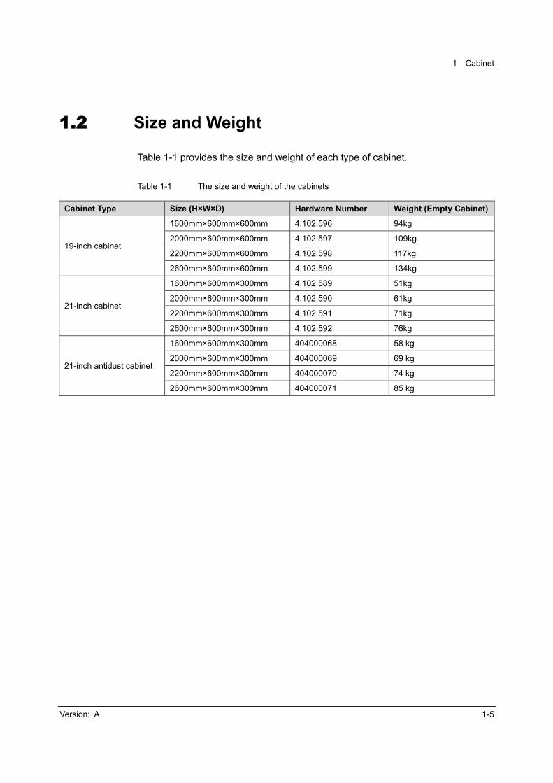
1.2 Size and Weight
Table 1-1 provides the size and weight of each type of cabinet.
Table 1-1 The size and weight of the cabinets
Cabinet Type Size (H×W×D) Hardware Number Weight (Empty Cabinet)
19-inch cabinet
1600mm×600mm×600mm 4.102.596 94kg
2000mm×600mm×600mm 4.102.597 109kg
2200mm×600mm×600mm 4.102.598 117kg
2600mm×600mm×600mm 4.102.599 134kg
21-inch cabinet
1600mm×600mm×300mm 4.102.589 51kg
2000mm×600mm×300mm 4.102.590 61kg
2200mm×600mm×300mm 4.102.591 71kg
2600mm×600mm×300mm 4.102.592 76kg
21-inch antidust cabinet
1600mm×600mm×300mm 404000068 58 kg
2000mm×600mm×300mm 404000069 69 kg
2200mm×600mm×300mm 404000070 74 kg
2600mm×600mm×300mm 404000071 85 kg

AN5516-06 Optical Line Terminal Equipment Hardware Description
1-6 Version: A
1.3 Structure
The structure and components of the 19-inch cabinet are illustrated in Figure 1-4.
(1) Mounting hole for the top-connection bent angle bracket (2) Wiring hole (top)
(3) Ventilation hole area (top) (4) LED (top)
(5) ESD protection earth ground fastener (6) Mounting hole on the vertical mounting flange
(7) Wiring hole(bottom) (8) Front door
(9) Side door (10) Latch (on the side door)
Figure 1-4 The 19-inch cabinet

1 Cabinet
Version: A 1-7
Three alarm indicator LEDs are installed on the top of the cabinet. Table 1-2
describes the meaning and status of each alarm LED.
Table 1-2 Descriptions of alarm indicator LEDs on the top of the 19-inch cabinet
Color Meaning Status Description
Red Emergency ON An emergency alarm in equipment
OFF No emergency alarm in equipment
Yellow Non-emergency ON A non-emergency alarm in a card
OFF No non-emergency alarm in equipment
Green Normal
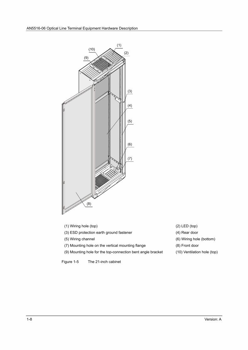
The structure and components of the 21-inch cabinet are illustrated in Figure 1-5.
AN5516-06 Optical Line Terminal Equipment Hardware Description
1-8 Version: A
(1) Wiring hole (top) (2) LED (top)
(3) ESD protection earth ground fastener (4) Rear door
(5) Wiring channel (6) Wiring hole (bottom)
(7) Mounting hole on the vertical mounting flange (8) Front door
(9) Mounting hole for the top-connection bent angle bracket (10) Ventilation hole (top)
Figure 1-5 The 21-inch cabinet

1 Cabinet
Version: A 1-9
Three alarm indicator LEDs are installed on the top of the cabinet. Table 1-3
describes the meaning and status of each alarm LED.
Table 1-3 Descriptions of alarm indicator LEDs on the top of the 21-inch cabinet
Color Meaning Status Description
Red Emergency ON An emergency alarm in equipment
OFF No emergency alarm in equipment
Yellow Non-emergency ON A non-emergency alarm in a card
OFF No non-emergency alarm in equipment
Green Normal
The structure and components of the 21-inch antidust cabinet are illustrated in
Figure 1-6.

AN5516-06 Optical Line Terminal Equipment Hardware Description
1-10 Version: A
(1) Wiring hole (top) (2) LED (top)
(3) Wiring channel (4) Rear door
(5) ESD protection earth ground fastener (6) Mounting hole on the vertical mounting flange
(7) Wiring hole (bottom) (8) Front door
(9) Mounting hole for the top-connection bent angle bracket (10) Ventilation hole (top)
Figure 1-6 The 21-inch antidust cabinet

1 Cabinet
Version: A 1-11
Three alarm indicator LEDs are installed on the top of the cabinet. Table 1-4
describes the meaning and status of each alarm LED.
Table 1-4 Descriptions of alarm indicator LEDs on the 21-inch antidust cabinet
Color Meaning Status Description
Red Emergency ON An emergency alarm in equipment
OFF No emergency alarm in equipment
Yellow Non-emergency ON A non-emergency alarm in a card
OFF No non-emergency alarm in equipment
Green Normal

AN5516-06 Optical Line Terminal Equipment Hardware Description
1-12 Version: A
1.4 Typical Layout
Cabinets of different specifications can house different number of AN5516-06
subracks. A cabinet can hold up to two subracks.
Figure 1-7 Typical layout of the 19-inch cabinet

1 Cabinet
Version: A 1-13
Door lintel
Door lintel
Door lintel
Door lintel Door lintel
Door lintel
Door lintel
Door lintel
PDP (100)
AN5516-06 subrack (300)
Empty (≥100)
Empty (≥100)
AN5516-06 subrack (300)
Empty (≥100)
PDP (100)
AN5516-06 subrack (300)
Empty (≥100)
Empty (≥100)
AN5516-06 subrack (300)
Empty (≥100)
PDP (100)
AN5516-06 subrack (300)
Empty (≥100)
Empty (≥100)
AN5516-06 subrack (300)
Empty (≥100)
PDP (100)
AN5516-06 subrack (300)
Empty (≥100)
Empty (≥100)
Figure 1-8 Typical layout of the 21-inch cabinet

AN5516-06 Optical Line Terminal Equipment Hardware Description
1-14 Version: A
1.5 Ventilation Principle
The principle of ventilation inside the cabinet is illustrated in Figure 1-9 and Figure
1-10. A flow of air is forced by the air guide unit at the lower part of the subrack into
the cabinet. After being blown by the fan unit on the left of the subrack, the cooling
air passes rightward through the subracks and is exhausted from the top of the
cabinet.

1 Cabinet
Version: A 1-15
Figure 1-9 An illustration of ventilation principle for a 19-inch cabinet

AN5516-06 Optical Line Terminal Equipment Hardware Description
1-16 Version: A
Figure 1-10 An illustration of ventilation principle for a 21-inch cabinet

Version: A 2-1
2 PDP
This chapter introduces the AN5516-06 PDP and includes the following contents:
Function
Structure
Power connector
Alarm terminal
Lightning-protection module
Specifications

AN5516-06 Optical Line Terminal Equipment Hardware Description
2-2 Version: A
2.1 Function
The PDP used by the AN5516-06 is PDP296B. It inducts two channels of -48V
power (active and standby) from the external (e.g. the power cabinet) and provides
three sets of redundant branch power rails (six branch power rails totally) for three
subracks. Meanwhile, the PDP performs functions such as lightning protection and
alarm signal processing.

2 PDP
Version: A 2-3
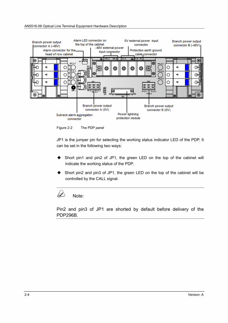
2.2 Structure
The structure of the PDP296B is illustrated in Figure 2-1 and Figure 2-2.
Note:
After being installed with different mounting ears, the PDP296B can be mounted in a 19-inch cabinet or a 21-inch cabinet.
Figure 2-1 The PDP structure
Connectors, switches and other components are provided on the panel of the PDP,
as shown in Figure 2-2.
AN5516-06 Optical Line Terminal Equipment Hardware Description
2-4 Version: A
Figure 2-2 The PDP panel
JP1 is the jumper pin for selecting the working status indicator LED of the PDP. It
can be set in the following two ways:
Short pin1 and pin2 of JP1, the green LED on the top of the cabinet will
indicate the working status of the PDP.
Short pin2 and pin3 of JP1, the green LED on the top of the cabinet will be
controlled by the CALL signal.
Note:
Pin2 and pin3 of JP1 are shorted by default before delivery of the PDP296B.
2 PDP
Version: A 2-5
2.3 Power Connector
2.3.1 Main and Branch Power Supply Connector Posts
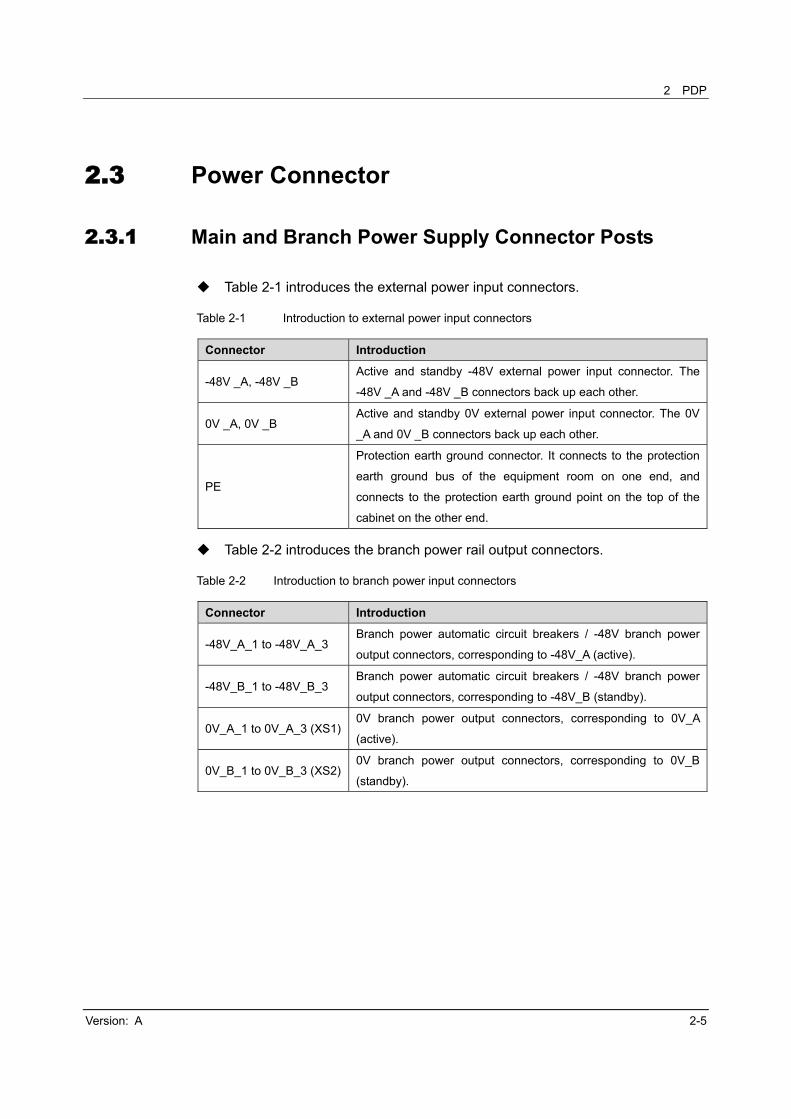
Table 2-1 introduces the external power input connectors.
Table 2-1 Introduction to external power input connectors
Connector Introduction
-48V _A, -48V _B Active and standby -48V external power input connector. The
-48V _A and -48V _B connectors back up each other.
0V _A, 0V _B Active and standby 0V external power input connector. The 0V
_A and 0V _B connectors back up each other.
PE
Protection earth ground connector. It connects to the protection
earth ground bus of the equipment room on one end, and
connects to the protection earth ground point on the top of the
cabinet on the other end.
Table 2-2 introduces the branch power rail output connectors.
Table 2-2 Introduction to branch power input connectors
Connector Introduction
-48V_A_1 to -48V_A_3 Branch power automatic circuit breakers / -48V branch power
output connectors, corresponding to -48V_A (active).
-48V_B_1 to -48V_B_3 Branch power automatic circuit breakers / -48V branch power
output connectors, corresponding to -48V_B (standby).
0V_A_1 to 0V_A_3 (XS1)0V branch power output connectors, corresponding to 0V_A
(active).
0V_B_1 to 0V_B_3 (XS2)0V branch power output connectors, corresponding to 0V_B
(standby).
AN5516-06 Optical Line Terminal Equipment Hardware Description
2-6 Version: A
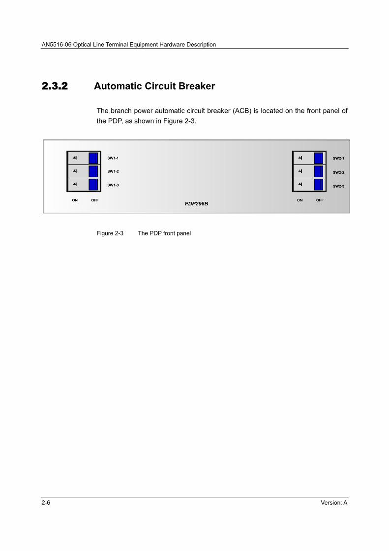
2.3.2 Automatic Circuit Breaker
The branch power automatic circuit breaker (ACB) is located on the front panel of
the PDP, as shown in Figure 2-3.
Figure 2-3 The PDP front panel

2 PDP
Version: A 2-7
2.4 Alarm Terminal
Subrack alarm aggregation terminal
The three RJ45 sockets AlmIn1 to Almln3 on the PDP are subrack alarm
aggregation terminals.
Alarm output terminal (connected to the head of row cabinet)
The alarm output terminal (connected to the head of row cabinet) XP1 is a
three-conductor D-type socket.
Alarm output terminal (connected to the alarm LED on the cabinet top)
The alarm output terminal (connected to the alarm LED on the cabinet top)
XS4 is a six-conductor D-type socket.
2.5 Lightning Protection Module
The hardware number of the power lightning protection module is WKE3.578.403.
The standard DB-25 plug is used to connect with the lightning protection module
socket (XS3) on the PDP. The lightning protection module can withstand the surge
of 2KV (1.2/50us-8/20us combination wave) under the common mode, and
withstand the surge of 1kV under the differential mode, so as to guarantee the
normal work of the equipment.

AN5516-06 Optical Line Terminal Equipment Hardware Description
2-8 Version: A
2.6 Specifications
Table 2-3 shows the relevant specifications of the PDP.
Table 2-3 The PDP specifications
Item Parameter
Input
features
Range of input voltage -38V to -60V
Input mode Inducts two channels of power (active and standby).
Maximum input current The maximum current of a single channel of power is 96A.
Output
features
Range of output
voltage -38V to -60V
Output power rails Outputs six branch power rails.
Output current The maximum current of a branch power rail is 32A.
Functions
Protection against
reverse polarity
connection
The PDP will not be damaged when polarities of the external power
supply are reversely connected.
Alarm signal
processing
Receives signals of alarm reported by the corresponding equipment;
provides acoustic alarm according to the alarm signals, illuminates the
indicator LED on the cabinet top, and outputs alarm signals to the
upper-layer device (e.g. the head of row cabinet).
Differential mode
protection
Withstands a surge current of 8/20Us/2kA between -48V and 0V,
respectively five times for the positive and negative directions. After the
surge current testing, the PDP will operate normally.
Common mode
protection
Withstands a surge current of 8/20Us/2kA between -48V and PE and
between 0V and PE, respectively five times for the positive and negative
directions. After the surge current testing, the PDP will operate normally.
Alarm-reporting
function of the lightning
protection module
When the lightning protection module fails to work, the PDP will output
the lightning protection failure alarm signals to the equipment, and the
equipment will then report the alarm to the network management system.
Environment
Working temperature -10 to 55
Storage temperature -40 to 70
Relative humidity ≤95%
Atmospheric pressure 70 KPa to 106KPa

Version: A 3-1
3 Subrack
This chapter introduces the AN5516-06 subrack, and includes the following
sections:
Structure
Size and weight
Subrack configuration
Fan unit

AN5516-06 Optical Line Terminal Equipment Hardware Description
3-2 Version: A
3.1 Structure
The hardware number of the subrack is 3.061.098. The structure and names of
various components of the subrack are illustrated in Figure 3-1.
Figure 3-1 Subrack structure
3.2 Size and Weight
Table 3-1 shows the size and weight of the subrack.
Table 3-1 The size and weight of the subrack
Item Parameter
Size (Height×Width×Depth) 265.9mm×530mm×230.5mm
Weight (a subrack with only the fans installed) 12kg
3 Subrack
Version: A 3-3
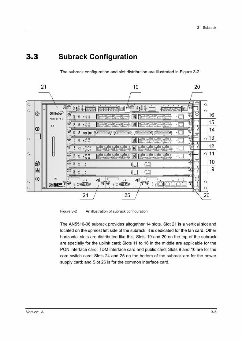
3.3 Subrack Configuration
The subrack configuration and slot distribution are illustrated in Figure 3-2.
Figure 3-2 An illustration of subrack configuration
The AN5516-06 subrack provides altogether 14 slots. Slot 21 is a vertical slot and
located on the upmost left side of the subrack. It is dedicated for the fan card. Other
horizontal slots are distributed like this: Slots 19 and 20 on the top of the subrack
are specially for the uplink card; Slots 11 to 16 in the middle are applicable for the
PON interface card, TDM interface card and public card; Slots 9 and 10 are for the
core switch card; Slots 24 and 25 on the bottom of the subrack are for the power
supply card; and Slot 26 is for the common interface card.

AN5516-06 Optical Line Terminal Equipment Hardware Description
3-4 Version: A
3.4 Fan Unit
3.4.1 Function
Located on the left side of the subrack, the fan unit is used for forced air cooling.
The fan unit supports intelligent progressive speed control with 8 speed choices.
Depending on the ambient temperature, it changes the speed to adjust air flow and
properly cool the equipment.
3.4.2 Appearance
The hardware number of the fan unit is 2.200.357.
The AN5516-06 is provided with one fan unit, which can be installed and removed
independently. Figure 3-3 illustrates the appearance of the fan unit.
Figure 3-3 The appearance of the fan unit
3 Subrack
Version: A 3-5
3.4.3 Specifications
Table 3-2 provides the size, weight and power consumption of the fan unit.
Table 3-2 Fan unit parameter table
Item Parameter
Fan size (Width×Height×Depth) 58.3 mm×244.3 mm×224.3mm
Fan weight 1.84kg
Fan power consumption
The maximum power consumption is 64W. The
typical power consumption is 20W when the input
voltage is -48V and the current is 0.42A.


Version: A 4-1
4 Card
This chapter introduces the functions, interfaces, indicator LEDs, keys and
technical specifications of all cards used in the AN5516-06. It includes the following
sections:
Appearance and structure
Card configuration table
HSWA card
EC4B card
EC8B card
GC4B card
GC8B card
HU1A card
HU2A card
GU6Fcard
CE1B card
C155A card
PUBA card
CIO card
PWR card

AN5516-06 Optical Line Terminal Equipment Hardware Description
4-2 Version: A
4.1 Appearance and Structure
The AN5516-06 cards can be classified into four categories as per the height of the
card panels.
Table 4-1 Classification of the AN5516-06 cards
Height of Card (mm) Example Card Refer to
366 EC4B Figure 4-1
182 HU1A Figure 4-2
113 PWR Figure 4-3
138 CIO Figure 4-4

4 Card
Version: A 4-3
Figure 4-1 Appearance and structure of the EC4B card

AN5516-06 Optical Line Terminal Equipment Hardware Description
4-4 Version: A
Figure 4-2 Appearance and structure of the HU1A card

4 Card
Version: A 4-5
Figure 4-3 Appearance and structure of the PWR card

AN5516-06 Optical Line Terminal Equipment Hardware Description
4-6 Version: A
Figure 4-4 Appearance and structure of the CIO card
Note:
The card number is indicated in a tag attached to the lower part of the PCB.

4 Card
Version: A 4-7
4.2 Card Configuration Table
Table 4-2 The AN5516-06 card configuration table
Type Slot Symbol Card Number Remarks
Core switch card 9, 10 HSWA 2.115.334
Performs the aggregation, switch and management
of traffic flow; processes Layer-2 protocols;
manages the troubleshooting, performance and
configuration of the equipment.
Provides a local Console management interface.
EPON interface
card 11 to 16
EC4B 2.119.318 Provides four EPON interfaces.
EC8B 2.119.354 Provides eight EPON interfaces.
GPON interface
card 11 to 16
GC4B 2.119.348 Provides four GPON interfaces.
GC8B 2.200.012 Provides eight GPON interfaces.
TDM interface
card 11 to 16
C155A 2.170.821 Provides two STM-1 uplink optical interfaces, and
achieves 1+1 protection.
CE1B 2.170.845 Provides 32 E1 uplink electrical interfaces.
Uplink card 19, 20
HU1A 2.170.846 Provides four GE uplink optical / electrical interfaces
and one 10GE uplink optical interface.
HU2A 2.170.854 Provides two GE uplink optical / electrical interfaces
and two 10GE uplink optical interfaces.
GU6F 2.170.855 Provides six GE uplink optical interfaces.
Public card 11 to 16 PUBA 2.167.177 Accesses the alarm signals from 14 dry contacts.
Fan card 21 FAN 2.200.357 Performs air cooling of the equipment and regulates
ambient temperature.
Power supply
card 24 to 25 PWR 2.200.354 Inducts one channel of -48V power.
Common
interface card 26 CIO 2.200.352
Provides the FE interface for the network
management system, the RS485 bus interface for
connection to external environment monitoring unit
and the interface for the alarm indicator LED on the
top of the cabinet. Meanwhile, the common interface
card performs the function of dry contact.

AN5516-06 Optical Line Terminal Equipment Hardware Description
4-8 Version: A
4.3 HSWA Card
Main functions
Provides a RS-232 interface to connect a local CLI network management
system computer.
Supports multiple management VLANs and multiple management IPs.
Supports up to twelve GE uplink interfaces or four 10GE uplink interfaces.
Supports the uplink port mirroring and trunking and supports uplink
redundancy.
Supports PON interface protection.
Supports multicast signaling function. Four multicast modes are provided:
Proxy, Snooping, Proxy-Snooping and controllable multicast.
Supports broadcast packet, multicast packet and unknown packet suppression
and prevents generation of broadcast storms on the network.
Supports port-based and IEEE 802.1q-based VLAN.
Supports flexible Q-in-Q VLAN and VLAN translation.
Supports three voice protocols: MGCP, SIP and H.248.
Supports remote software upgrade of all cards.
Supports RSTP to avoid generation of loops in the network.
Supports CoS queues and processes user services on the basis of CoS.
Supports environmental monitoring information and alarm information
reporting of the AN5516-06 and the connected ONUs.
Supports ACL functions and has a strict security protection mechanism.
Supports DHCP Snooping and DHCP Option 82.
Supports traffic shaping.
Supports layer 2 switch function.
Supports layer 2-7 packet classification.
4 Card
Version: A 4-9
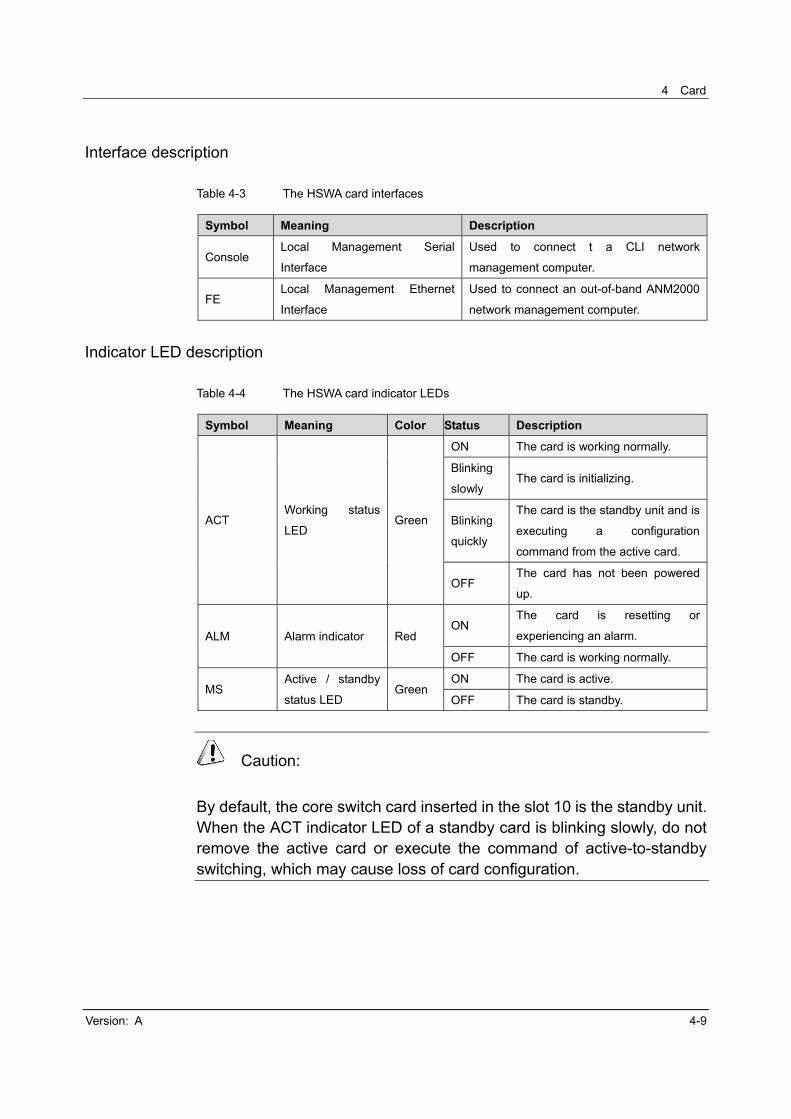
Interface description
Table 4-3 The HSWA card interfaces
Symbol Meaning Description
Console Local Management Serial
Interface
Used to connect t a CLI network
management computer.
FE Local Management Ethernet
Interface
Used to connect an out-of-band ANM2000
network management computer.
Indicator LED description
Table 4-4 The HSWA card indicator LEDs
Symbol Meaning Color Status Description
ACT Working status
LED Green
ON The card is working normally.
Blinking
slowly The card is initializing.
Blinking
quickly
The card is the standby unit and is
executing a configuration
command from the active card.
OFF The card has not been powered
up.
ALM Alarm indicator Red ON
The card is resetting or
experiencing an alarm.
OFF The card is working normally.
MS Active / standby
status LED Green
ON The card is active.
OFF The card is standby.
Caution:
By default, the core switch card inserted in the slot 10 is the standby unit. When the ACT indicator LED of a standby card is blinking slowly, do not remove the active card or execute the command of active-to-standby switching, which may cause loss of card configuration.

AN5516-06 Optical Line Terminal Equipment Hardware Description
4-10 Version: A
Key description
Table 4-5 The HSWA card key
Symbol Meaning Description
K1 Card reset key For resetting the card.
K1
The panel side The mounting side
Figure 4-5 The location of the key on the HSWA card
Caution:
The reset operation may result in interruption of all services carried by the AN5516-06. The reset operation is generally conducted in course of the card maintenance and upgrade. It is not recommended that the user directly issue a reset command using the reset key.

4 Card
Version: A 4-11
Technical specifications
Table 4-6 The HSWA card technical specifications
Item Specification
Network standards IEEE802.3, IEEE802.3u, IEEE 802.3z, IEEE802.3x, IEEE
802.1d, IEEE802.1p and IEEE 802.1q, etc.
Working modes supported 10/100/1000Mbit/s, 10Gbit/s (full duplex)
Switching mode Store-and-Forward
Capacity of the core switch
card 488Gbit/s
Backplane switch rate 960Gbit/s
Maximum packet forwarding
rate 14 881 000pps (10Gbps)
MAC address 32k
Buffer size 1Mbytes
Switching time ≤50ms
Power consumption ≤35W
Working temperature 0 to 45
Ambient temperature for
storage -30 to 60
Ambient humidity for storage 10% to 90%
AN5516-06 Optical Line Terminal Equipment Hardware Description
4-12 Version: A
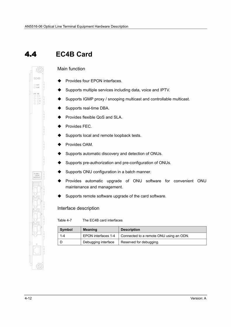
4.4 EC4B Card
Main function
Provides four EPON interfaces.
Supports multiple services including data, voice and IPTV.
Supports IGMP proxy / snooping multicast and controllable multicast.
Supports real-time DBA.
Provides flexible QoS and SLA.
Provides FEC.
Supports local and remote loopback tests.
Provides OAM.
Supports automatic discovery and detection of ONUs.
Supports pre-authorization and pre-configuration of ONUs.
Supports ONU configuration in a batch manner.
Provides automatic upgrade of ONU software for convenient ONU
maintenance and management.
Supports remote software upgrade of the card software.
Interface description
Table 4-7 The EC4B card interfaces
Symbol Meaning Description
1-4 EPON interfaces 1-4 Connected to a remote ONU using an ODN.
D Debugging interface Reserved for debugging.

4 Card
Version: A 4-13
Indicator LED description
Table 4-8 The EC4B card indicator LEDs
Symbol Meaning Color Status Description
ACT Working
status LEDGreen
ON The card is working normally.
Blinking
slowly
The card is initializing or the software
is starting. The communication link
between the active card and the
standby card has not been established
yet.
Blinking
quickly
The card is executing a configuration
command or is establishing a
communication link between the active
card and the standby card.
OFF The card has not been powered on or
the software has not been started.
ALM Alarm
indicator Red
ON
The card is resetting, experiencing an
alarm or has failed to establish a
communication link between the active
card and the standby card.
OFF The card is working normally.
LNK1-4 Port status
LEDs Green
ON A remote ONU is connected and
authorized.
OFF No remote ONU is connected or
authorized.
MS1-4
Active /
Standby
status
LEDs
Green
ON The optical interface is active in a PON
protection group.
OFF
The optical interface is the standby
unit in a PON protection group; or not
configured with any PON protection
group.

AN5516-06 Optical Line Terminal Equipment Hardware Description
4-14 Version: A
Key description
Table 4-9 The EC4B card keys
Symbol Meaning Description
K1 Reset key of EPON
interfaces 1 & 2
For EPON1 system reset. May result in
interruption of the connected ONU services of
EPON interfaces 1 & 2.
K2 Reset key of EPON
interfaces 3 & 4
For EPON2 system reset. May result in
interruption of the connected ONU services of
EPON interfaces 3 & 4.
K3 Reset key of the card For card reset. May result in interruption of all
connected ONU services.
K1 K2 K3
The panel side The mounting side
Figure 4-6 The location of the keys of the EC4B card
Caution:
The reset operation may result in interruption of all ONU services carried by the EC4B card. The reset operation is generally conducted in course of the card maintenance and upgrade. It is not recommended that the user directly issue a reset command using the reset key.

4 Card
Version: A 4-15
Technical Specification
Table 4-10 The EC4B card technical specification
Item Specification
Network standard IEEE802.3, IEEE802.3ah, IEEE802.3u, IEEE 802.3z,
IEEE802.3x, IEEE 802.1d, IEEE802.1p, IEEE 802.1q, etc.
Working mode supported Full duplex / half duplex
Switching mode Store-and-Forward
Maximum package
forwarding rate Wire-speed forwarding
MAC address 16k
Buffer size 512Mbytes
Maximum split ratio 1:64
Maximum LLID 256
Bandwidth allocation
granularity 64kbit/s
Optical fiber connector SC / PC
Network cable
1000BASE-PX10: G.652 single-mode fiber, transmission
distance ≥10km
1000BASE-PX20: G.652 single-mode fiber, transmission
distance≥20km
Power consumption ≤40W
Working temperature 0 to 45
Ambient temperature for
storage -30 to 60
Ambient humidity for
storage 10% to 90%

AN5516-06 Optical Line Terminal Equipment Hardware Description
4-16 Version: A
4.5 EC8B Card
Main function
Provides eight EPON interfaces.
Supports multiple services including data, voice and IPTV.
Supports IGMP proxy / snooping multicast and controllable multicast.
Supports real-time DBA.
Provides flexible QoS and SLA.
Provides FEC.
Supports local and remote loopback tests.
Provides OAM.
Supports automatic discovery and detection of ONUs.
Supports pre-authorization and pre-configuration of ONUs.
Supports ONU configuration in a batch manner.
Provides automatic upgrade of ONU software for convenient ONU
maintenance and management.
Supports remote software upgrade of the card software.
Interface description
Table 4-11 The EC8B card interfaces
Symbol Meaning Description
1-8 EPON interfaces 1-8 Connected to a remote ONU using an ODN.
D Debugging interface Reserved for debugging.
4 Card
Version: A 4-17
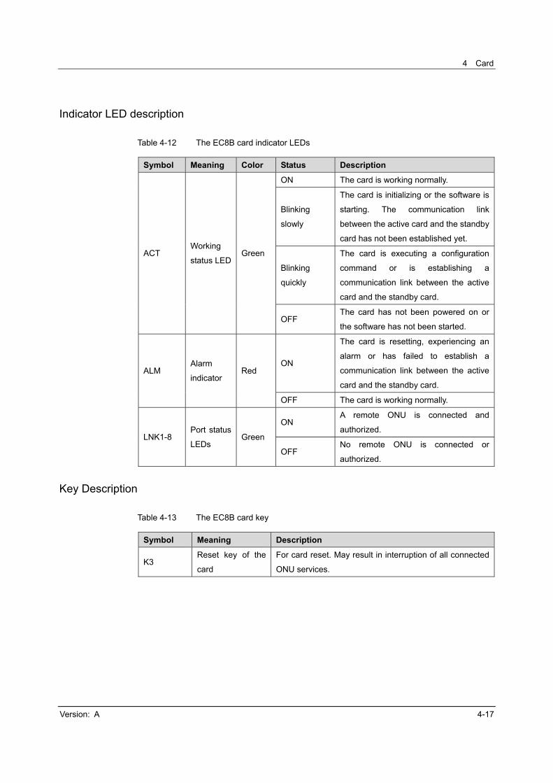
Indicator LED description
Table 4-12 The EC8B card indicator LEDs
Symbol Meaning Color Status Description
ACT Working
status LEDGreen
ON The card is working normally.
Blinking
slowly
The card is initializing or the software is
starting. The communication link
between the active card and the standby
card has not been established yet.
Blinking
quickly
The card is executing a configuration
command or is establishing a
communication link between the active
card and the standby card.
OFF The card has not been powered on or
the software has not been started.
ALM Alarm
indicator Red
ON
The card is resetting, experiencing an
alarm or has failed to establish a
communication link between the active
card and the standby card.
OFF The card is working normally.
LNK1-8 Port status
LEDs Green
ON A remote ONU is connected and
authorized.
OFF No remote ONU is connected or
authorized.
Key Description
Table 4-13 The EC8B card key
Symbol Meaning Description
K3 Reset key of the
card
For card reset. May result in interruption of all connected
ONU services.
AN5516-06 Optical Line Terminal Equipment Hardware Description
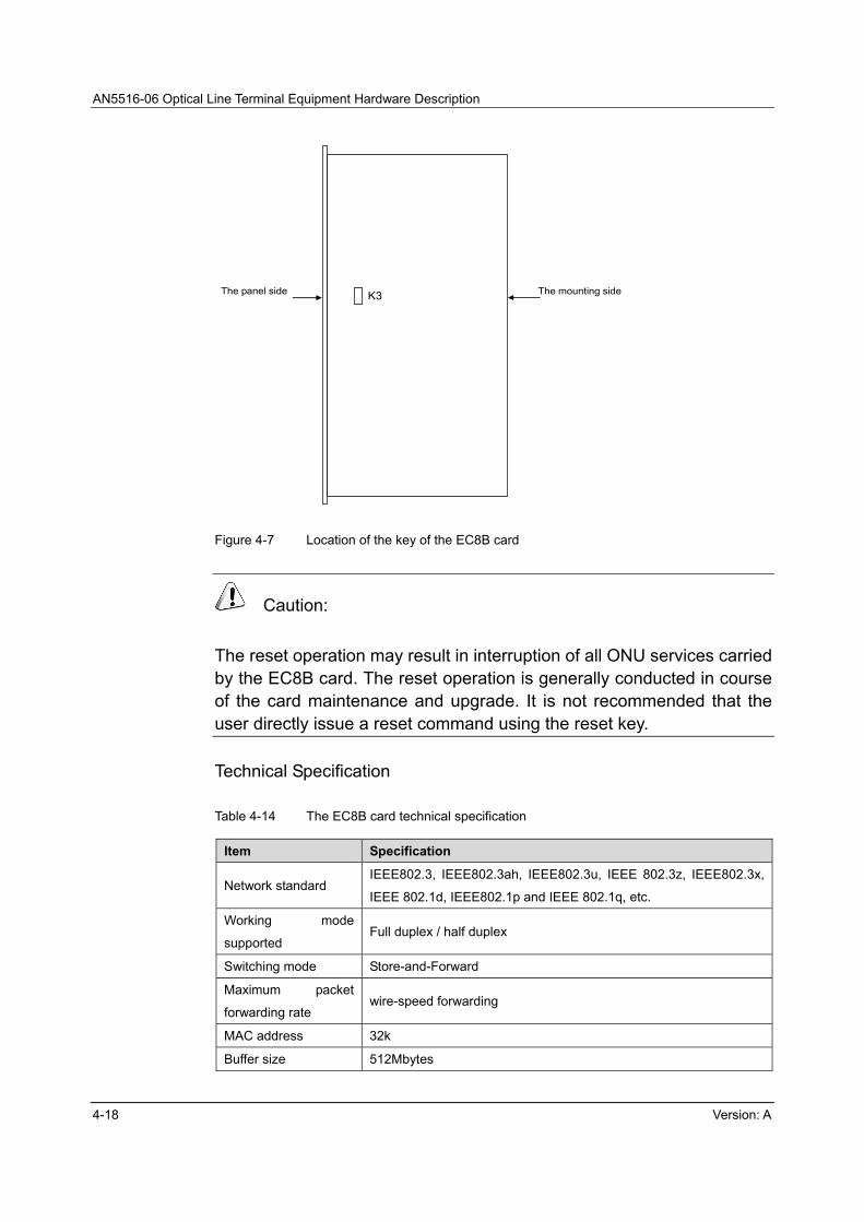
4-18 Version: A
K3 The panel side The mounting side
Figure 4-7 Location of the key of the EC8B card
Caution:
The reset operation may result in interruption of all ONU services carried by the EC8B card. The reset operation is generally conducted in course of the card maintenance and upgrade. It is not recommended that the user directly issue a reset command using the reset key.
Technical Specification
Table 4-14 The EC8B card technical specification
Item Specification
Network standard IEEE802.3, IEEE802.3ah, IEEE802.3u, IEEE 802.3z, IEEE802.3x,
IEEE 802.1d, IEEE802.1p and IEEE 802.1q, etc.
Working mode
supported Full duplex / half duplex
Switching mode Store-and-Forward
Maximum packet
forwarding rate wire-speed forwarding
MAC address 32k
Buffer size 512Mbytes

4 Card
Version: A 4-19
Item Specification
Maximum split ratio 1:64
Maximum LLID 256
Bandwidth allocation
granularity 64kbit/s
Optical fiber
connector SC/PC
Network cable
1000BASE-PX10: G.652 single-mode fiber, transmission distance
≥10km
1000BASE-PX20: G.652 single-mode fiber, transmission distance
≥20km
Power consumption ≤70W
Working temperature 0 to 45
Ambient temperature
for storage -30 to 60
Ambient humidity for
storage 10% to 90%

AN5516-06 Optical Line Terminal Equipment Hardware Description
4-20 Version: A
4.6 GC4B Card
Main function
Provides four GPON interfaces.
Supports multiple services including data, voice and IPTV.
Supports IGMP proxy / snooping multicast and controllable multicast.
Supports real-time DBA.
Provides flexible QoS and SLA.
Provides FEC.
Supports local and remote loopback tests.
Provides OAM.
Supports automatic discovery and detection of ONUs.
Supports pre-authorization and pre-configuration of ONUs.
Supports ONU configuration in a batch manner.
Supports remote software upgrade of the card software.
Interface description
Table 4-15 The GC4B card interfaces
Symbol Meaning Description
1-4 GPON interfaces 1-4 Connected to a remote ONU using an ODN.
D Debugging interface Reserved for debugging.

4 Card
Version: A 4-21
Indicator LED description
Table 4-16 The GC4B card indicator LEDs
Symbol Meaning Color Status Description
ACT Working
status LEDGreen
ON The card is working normally.
Blinking
slowly
The card is initializing or the software
is starting. The communication link
between the active card and the
standby card has not been established
yet.
Blinking
quickly
The card is executing a configuration
command or is establishing a
communication link between the active
card and the standby card.
OFF The card has not been powered on or
the software has not been started.
ALM Alarm
indicator Red
ON
The card is resetting, experiencing an
alarm or has failed to establish a
communication link between the active
card and the standby card.
OFF The card is working normally.
LNK1-4 Port status
LEDs Green
ON A remote ONU is connected and
authorized.
OFF No remote ONU is connected or
authorized.
MS1-4
Active /
Standby
status
LEDs
Green
ON The optical interface is active in a PON
protection group.
OFF
The optical interface is the standby
unit in a PON protection group; or not
configured with any PON protection
group.
Key description
Table 4-17 The GC4B card key
Symbol Meaning Description
K1 Reset key of the card For card reset. May result in interruption of all
connected ONU services.

AN5516-06 Optical Line Terminal Equipment Hardware Description
4-22 Version: A
K1
The panel side The mounting side
Figure 4-8 Location of the key of the GC4B card
Caution:
The reset operation may result in interruption of all ONU services carried by the GC4B card. The reset operation is generally conducted in course of the card maintenance and upgrade. It is not recommended that the user directly issue a reset command using the reset key.
Technical Specification
Table 4-18 The GC4B card technical specification
Item Specification
Network standard
IEEE802.3, IEEE802.3ah, IEEE802.3u, IEEE 802.3z,
IEEE802.3x, IEEE 802.1d, IEEE802.1p, IEEE 802.1q,
etc.
Working mode supported Full duplex / half duplex
Switching mode Store-and-Forward
Maximum packet forwarding rate 14881000bit/s (10GBASE-LR)
MAC address 32k
Buffer size 128Mbytes
Maximum split ratio 1:64
4 Card
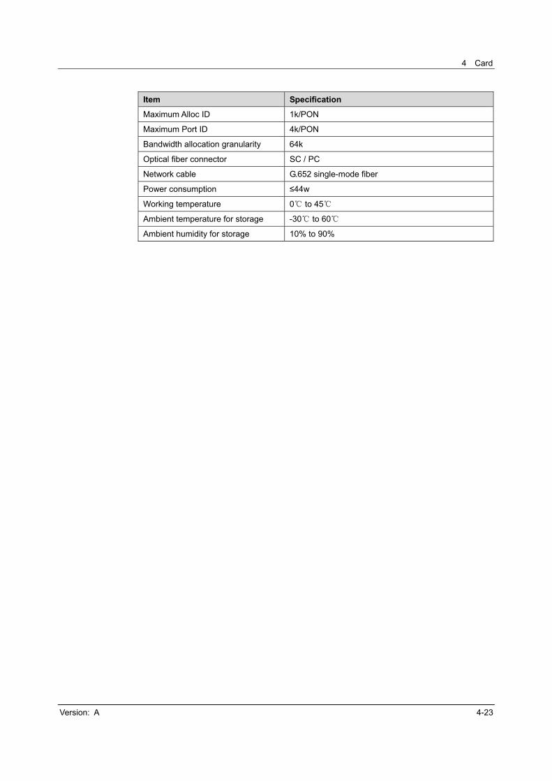
Version: A 4-23
Item Specification
Maximum Alloc ID 1k/PON
Maximum Port ID 4k/PON
Bandwidth allocation granularity 64k
Optical fiber connector SC / PC
Network cable G.652 single-mode fiber
Power consumption ≤44w
Working temperature 0 to 45
Ambient temperature for storage -30 to 60
Ambient humidity for storage 10% to 90%

AN5516-06 Optical Line Terminal Equipment Hardware Description
4-24 Version: A
4.7 GC8B Card
Main function
Provides eight GPON interfaces.
Supports multiple services including data, voice and IPTV.
Supports IGMP proxy / snooping multicast and controllable multicast.
Supports real-time DBA.
Provides flexible QoS and SLA.
Provides FEC.
Supports local and remote loopback tests.
Provides OAM.
Supports automatic discovery and detection of ONUs.
Supports pre-authorization and pre-configuration of ONUs.
Supports ONU configuration in a batch manner.
Supports remote software upgrade of the card software.
Interface description
Table 4-19 The GC8B card interfaces
Symbol Meaning Description
1-8 GPON interfaces 1-8 Connected to a remote ONU using an ODN.
D Debugging interface Reserved for debugging.

4 Card
Version: A 4-25
Indicator LED description
Table 4-20 The GC8B card indicator LEDs
Symbol Meaning Color Status Description
ACT Working
status LEDGreen
ON The card is working normally.
Blinking
slowly
The card is initializing or the
software is starting. The
communication link between the
active card and the standby card
has not been established yet.
Blinking
quickly
The card is executing a
configuration command or is
establishing a communication link
between the active card and the
standby card.
OFF
The card has not been powered on
or the software has not been
started.
ALM Alarm
indicator Red
ON
The card is resetting, experiencing
an alarm or has failed to establish a
communication link between the
active card and the standby card.
OFF The card is working normally.
LNK1-8 Port status
LEDs Green
ON A remote ONU is connected and
authorized.
OFF No remote ONU is connected or
authorized.
Key description
Table 4-21 The GC8B card key
Symbol Meaning Description
K1 Reset key of the cardFor card reset. May result in interruption of all
connected ONU services.

AN5516-06 Optical Line Terminal Equipment Hardware Description
4-26 Version: A
K1
The panel side The mounting side
Figure 4-9 Location of the key of the GC8B card
Caution:
The reset operation may result in interruption of all ONU services carried by the GC8B card. The reset operation is generally conducted in course of the card maintenance and upgrade. It is not recommended that the user directly issue a reset command using the reset key.
Technical specification
Table 4-22 The GC8B card technical specification
Item Specification
Network standard IEEE802.3, IEEE802.3ah, IEEE802.3u, IEEE 802.3z, IEEE802.3x,
IEEE 802.1d, IEEE802.1p, IEEE 802.1q, etc.
Working mode
supported Full duplex / half duplex
Switching mode Store-and-Forward
Maximum packet
forwarding rate 14881000bit/s (10GBASE-LR)
MAC address 32k
Buffer size 256Mbytes

4 Card
Version: A 4-27
Item Specification
Maximum split ratio 1:64
Maximum Alloc ID 1k/PON
Maximum Port ID 4k/PON
Bandwidth allocation
granularity 64k
Optical fiber
connector SC / PC
Network cable G.652 single-mode fiber
Power consumption ≤60W
Working temperature 0 to 45
Ambient temperature
for storage -30 to 60
Ambient humidity for
storage 10% to 90%

AN5516-06 Optical Line Terminal Equipment Hardware Description
4-28 Version: A
4.8 HU1A Card
Main function
Provides four GE uplink optical / electrical interfaces and one 10GE uplink
optical interface. The four GE uplink optical interfaces support the replacement
of GE optical / electrical module; uplink optical interfaces 3 and 4 are
self-adaptive to the opposite-end equipment.
Each uplink interface can be used as an in-band network management
interface to connect a network management computer.
Each uplink interface can be used as a cascade interface allowing multiple
devices to be cascaded to the IP network via a single IP port.
Interface description
Table 4-23 The HU1A card interfaces
Symbol Meaning Description
XFP 10GE uplink optical
interface
Provides10GE uplink optical interface and is connected
with the IP network.
SFP GE uplink optical /
electrical interface
Provides GE uplink optical / electrical interface and is
connected with the IP network.
Indicator LED description
Table 4-24 The HU1A card indicator LEDs
Symbol Meaning Color Status Description
ACT Working status
LED Green
ON The card is working normally.
Blinking
slowly The card is initializing.
Blinking
quickly
The card is executing a
configuration command.
OFF The card is not powered on.
ALM Alarm Indicator
LED Red
ON The card is resetting or
experiencing an alarm.
OFF The card is working normally.

4 Card
Version: A 4-29
Symbol Meaning Color Status Description
LNK1-5 Port status
LEDs Green
ON The port is linked up.
Blinking
quickly
The uplink port is transmitting
data to or receiving data from the
upper level equipment, for
example, switches.
OFF The port is not linked up.
WAN WAN / LAN
LED Green
ON The WAN mode of 10GE
interface.
OFF The LAN mode of 10GE
interface.
Technical specification
Table 4-25 The HU1A card technical specification
Item Specification
Network standard IEEE802.3, IEEE802.3z, IEEE802.3ae, etc.
Optical module interface
standard XENPAK/X2 3.0, XPAK MSA, XFP/XFI/SFP+, etc.
Working mode supported 1000Mbps, 10Gbps (full duplex)
Power consumption ≤6 W
Working temperature 0 to 45
Ambient temperature for
storage -30 to 60
Ambient humidity for storage 10% to 90%

AN5516-06 Optical Line Terminal Equipment Hardware Description
4-30 Version: A
4.9 HU2A Card
Main function
Provides two GE uplink optical / electrical interfaces (replace the optical /
electrical module to select the optical / electrical interface) and two 10GE
uplink optical interfaces.
Each uplink interface can be used as an in-band network management
interface to connect a network management computer.
Each uplink interface can be used as a cascade interface allowing multiple
devices to be cascaded to the IP network via a single IP port.
Interface description
Table 4-26 The HU2A card interfaces
Symbol Meaning Description
XG 10GE uplink
optical interface
Provides 10GE uplink optical interface and is connected
with the IP network.
GE GE uplink optical /
electrical interface
Provides GE uplink optical / electrical interface and is
connected with the IP network.
Indicator LED description
Table 4-27 The HU2A card indicator LEDs
Symbol Meaning Color Status Description
ACT Working
status LED Green
ON The card is working normally.
Blinking
slowly The card is initializing.
Blinking
quickly
The card is executing a
configuration command.
OFF The card is not powered on.
ALM Alarm
Indicator Red
ON The card is resetting or
experiencing an alarm.
OFF The card is working normally.
4 Card
Version: A 4-31
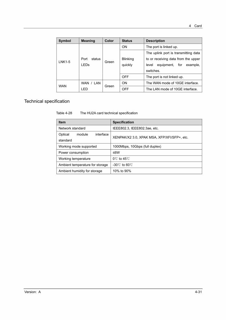
Symbol Meaning Color Status Description
LNK1-5 Port status
LEDs Green
ON The port is linked up.
Blinking
quickly
The uplink port is transmitting data
to or receiving data from the upper
level equipment, for example,
switches.
OFF The port is not linked up.
WAN WAN / LAN
LED Green
ON The WAN mode of 10GE interface.
OFF The LAN mode of 10GE interface.
Technical specification
Table 4-28 The HU2A card technical specification
Item Specification
Network standard IEEE802.3, IEEE802.3ae, etc.
Optical module interface
standard XENPAK/X2 3.0, XPAK MSA, XFP/XFI/SFP+, etc.
Working mode supported 1000Mbps, 10Gbps (full duplex)
Power consumption ≤6W
Working temperature 0 to 45
Ambient temperature for storage -30 to 60
Ambient humidity for storage 10% to 90%
AN5516-06 Optical Line Terminal Equipment Hardware Description
4-32 Version: A
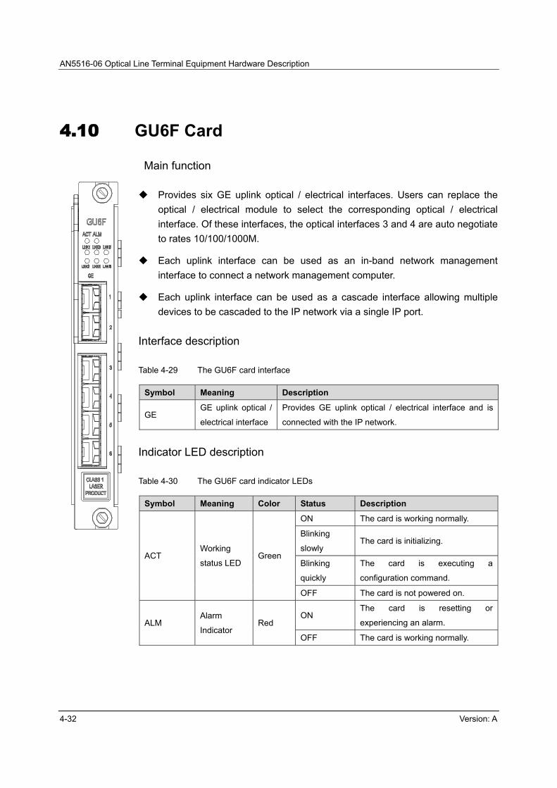
4.10 GU6F Card
Main function
Provides six GE uplink optical / electrical interfaces. Users can replace the
optical / electrical module to select the corresponding optical / electrical
interface. Of these interfaces, the optical interfaces 3 and 4 are auto negotiate
to rates 10/100/1000M.
Each uplink interface can be used as an in-band network management
interface to connect a network management computer.
Each uplink interface can be used as a cascade interface allowing multiple
devices to be cascaded to the IP network via a single IP port.
Interface description
Table 4-29 The GU6F card interface
Symbol Meaning Description
GE GE uplink optical /
electrical interface
Provides GE uplink optical / electrical interface and is
connected with the IP network.
Indicator LED description
Table 4-30 The GU6F card indicator LEDs
Symbol Meaning Color Status Description
ACT Working
status LED Green
ON The card is working normally.
Blinking
slowly The card is initializing.
Blinking
quickly
The card is executing a
configuration command.
OFF The card is not powered on.
ALM Alarm
Indicator Red
ON The card is resetting or
experiencing an alarm.
OFF The card is working normally.
4 Card
Version: A 4-33
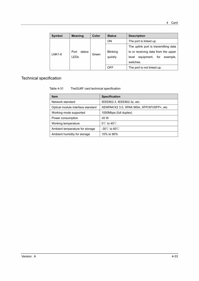
Symbol Meaning Color Status Description
LNK1-6 Port status
LEDs Green
ON The port is linked up.
Blinking
quickly
The uplink port is transmitting data
to or receiving data from the upper
level equipment, for example,
switches.
OFF The port is not linked up.
Technical specification
Table 4-31 TheGU6F card technical specification
Item Specification
Network standard IEEE802.3, IEEE802.3z, etc.
Optical module interface standard XENPAK/X2 3.0, XPAK MSA, XFP/XFI/SFP+, etc.
Working mode supported 1000Mbps (full duplex)
Power consumption ≤5 W
Working temperature 0 to 45
Ambient temperature for storage -30 to 60
Ambient humidity for storage 10% to 90%

AN5516-06 Optical Line Terminal Equipment Hardware Description
4-34 Version: A
4.11 CE1B Card
Main function
Provides 32 E1 uplink interfaces.
Supports E1 circuit emulation.
Supports four clock acquisition modes: Clock extraction from the input E1 line,
external input reference clock, internal free running clock and clock received
from other clock cards. The clock acquisition modes can be selected
according to the network condition.
Interface description
Table 4-32 The CE1B card interfaces
Symbol Meaning Description
E1-E32 E1 interface Provides E1 interfaces and is connected with the
transmission network.
CLIK IN Clock input
interface For introduction of the external clock.
CLIK OUT Clock output
interface
Connects the clock input of cascade equipment to
synchronize the clock.
Indicator LED description
Table 4-33 The CE1B card indicator LEDs
Symbol Meaning Color Status Description
ACT
Working
status
LED
Green
ON The card is working normally.
Blinking
slowly The card is initializing.
Blinking
quickly
The card is executing a configuration
command.
OFF The card is not powered on.
ALM Alarm
indicator Red
ON The card is resetting or experiencing
an alarm.
OFF The card is working normally.

4 Card
Version: A 4-35
Key description
Table 4-34 The CE1B card key
Symbol Meaning Description
K1 Reset key of the cardFor card reset. May result in interruption of all hosted
services.
K1
The panel side The mounting side
Figure 4-10 Location of the key of the CE1B card
Caution:
The reset operation may result in interruption of all services carried by the CE1B card. The reset operation is generally conducted in course of the card maintenance and upgrade. It is not recommended that the user directly issue a reset command using the reset key.
Technical specification
Table 4-35 The CE1B card technical specification
Item Specification
Network standard IEEE802.3, PWE3, G.825
Working mode supported 75Ω unbalanced

AN5516-06 Optical Line Terminal Equipment Hardware Description
4-36 Version: A
Item Specification
Delay Loopback delay <3ms
Bit error ratio Free of bit error in 24 hours.
Power consumption ≤40W
Working temperature 0 to 45
Ambient temperature for storage -30 to 60
Ambient humidity for storage 10% to 90%

4 Card
Version: A 4-37
4.12 C155A Card
Main function
Provides two STM-1 uplink optical interfaces and implements 1+1 protection.
Supports E1 circuit emulation.
Supports four clock acquisition modes: clock extraction from the input E1 line,
external input reference clock, internal free running clock and clock received
from other clock cards. The clock acquisition modes can be selected
according to the network condition.
Interface description
Table 4-36 The C155A card interfaces
Symbol Meaning Description
CLIK IN1 Clock input
interface The first external clock input
CLIK IN2 Clock input
interface The second external clock input
CLIK OUT Clock output
interface The external clock output
1-2 STM-1 uplink
optical interface
Provides two STM-1 optical interfaces and is
connected with the transmission network. If the two
interfaces are used at the same time, optical interface 1
will be active by default.
Indicator LED description
Table 4-37 The C155A card indicator LEDs
Symbol Meaning Color Status Description
ACT Working
status LED Green
ON The card is working normally.
Blinking
slowly The card is initializing.
Blinking
quickly
The card is executing a
configuration command.
OFF The card is not powered on.

AN5516-06 Optical Line Terminal Equipment Hardware Description
4-38 Version: A
Symbol Meaning Color Status Description
ALM Alarm
indicator Red
ON The card is resetting or
experiencing an alarm.
OFF The card is working normally.
LNK1-2 Port status
LEDs Green
ON The optical interface is linked up.
Blinking
quickly
The optical interface is transmitting
or receiving data.
OFF The optical interface is not linked
up.
MS1-2 Active/standb
y status LEDsGreen
ON The optical interface is active.
OFF The optical interface is the standby
unit.
Key description
Table 4-38 The C155A card key
Symbol Meaning Description
K1 Reset key of the
card
For card reset. May result in interruption of all hosted
services.
K1
The panel side The mounting side
Figure 4-11 Location of the key of the C155A card

4 Card
Version: A 4-39
Caution:
The reset operation may result in interruption of all services carried by the C155A card. The reset operation is generally conducted in course of the card maintenance and upgrade. It is not recommended that the user directly issue a reset command using the reset key.
Technical Specification
Table 4-39 The C155A card technical specification
Item Specification
Network standard IEEE802.3, PWE3, G.825
Working mode supported STM-1
Delay Loopback delay <3ms
Bit error ratio Free of bit error in 24 hours.
Power consumption ≤40W
Working temperature 0 to 45
Ambient temperature for storage -30 to 60
Ambient humidity for storage 10% to 90%
AN5516-06 Optical Line Terminal Equipment Hardware Description
4-40 Version: A
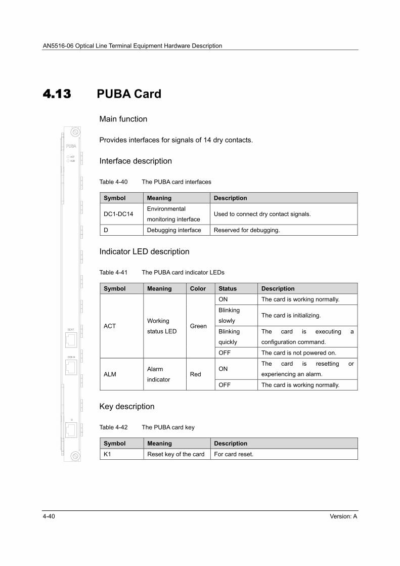
4.13 PUBA Card
Main function
Provides interfaces for signals of 14 dry contacts.
Interface description
Table 4-40 The PUBA card interfaces
Symbol Meaning Description
DC1-DC14 Environmental
monitoring interface Used to connect dry contact signals.
D Debugging interface Reserved for debugging.
Indicator LED description
Table 4-41 The PUBA card indicator LEDs
Symbol Meaning Color Status Description
ACT Working
status LED Green
ON The card is working normally.
Blinking
slowly The card is initializing.
Blinking
quickly
The card is executing a
configuration command.
OFF The card is not powered on.
ALM Alarm
indicator Red
ON The card is resetting or
experiencing an alarm.
OFF The card is working normally.
Key description
Table 4-42 The PUBA card key
Symbol Meaning Description
K1 Reset key of the card For card reset.

4 Card
Version: A 4-41
K1
The panel side The mounting side
Figure 4-12 Location of the key of the PUBA card
Caution:
The reset operation may result in interruption of all services carried by the PUBA card. The reset operation is generally conducted in course of the card maintenance and upgrade. It is not recommended that the user directly issue a reset command using the reset key.
Technical Specification
Table 4-43 The PUBA card technical specification
Item Specification
Network standard
IEEE802.3ah, IEEE802.3, IEEE802.3u, IEEE 802.3z,
IEEE802.3x, IEEE 802.1d, IEEE 802.1p, IEEE 802.1q,
etc.
Switching mode Store-and-Forward
Power consumption ≤15 W
Working temperature 0 to 45
Ambient temperature for storage -30 to 60
Ambient humidity for storage 10% to 90%

AN5516-06 Optical Line Terminal Equipment Hardware Description
4-42 Version: A
4.14 CIO Card
Main function
Provides the EMS interface for out-of-band network management system.
Provides the RS485 environment monitoring interface.
Provides the alarm monitoring interface (ALM interface).
Provides signal input interfaces for 14 dry contacts.
Interface description
Table 4-44 The CIO card interfaces
Symbol Meaning Description
EMS
Out-of-band
network
management
interface
Connects to the out-of-band network management
equipment.
ALM Alarm interface Outputs the alarm reported by the equipment to the PDP,
cabinet top or the head of row cabinet.
ESC
Environment
monitoring
interface
Connects to an external environment monitoring device,
and reports the result of environment monitoring to the
network management system.
DC1-DC14 Dry contact
interface Accesses the signals of the dry contacts.
Indicator LED description
Table 4-45 The CIO card indicator LEDs
Symbol Meaning Color Status Description
ACT Working
status LEDGreen
ON The card is working normally.
Blinking
slowly The card is initializing.
OFF The card is not powered on.
ALM Alarm
indicator Red
ON The card is resetting or experiencing
an alarm.
OFF The card is working normally.

4 Card
Version: A 4-43
Technical specification
Table 4-46 The CIO card technical specification
Item Specification
Power consumption ≤2 W
Working temperature 0 to 45
Ambient temperature for storage -30 to 60
Ambient humidity for storage 10% to 90%
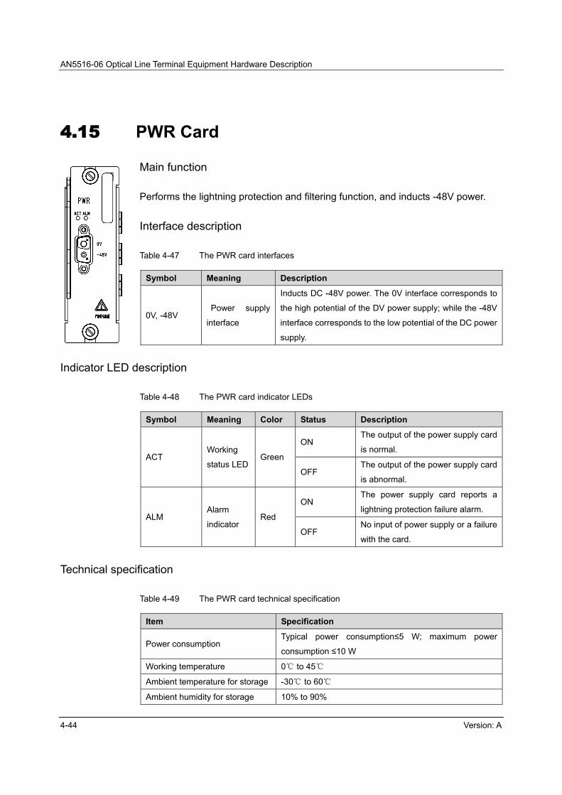
AN5516-06 Optical Line Terminal Equipment Hardware Description
4-44 Version: A
4.15 PWR Card
Main function
Performs the lightning protection and filtering function, and inducts -48V power.
Interface description
Table 4-47 The PWR card interfaces
Symbol Meaning Description
0V, -48V Power supply
interface
Inducts DC -48V power. The 0V interface corresponds to
the high potential of the DV power supply; while the -48V
interface corresponds to the low potential of the DC power
supply.
Indicator LED description
Table 4-48 The PWR card indicator LEDs
Symbol Meaning Color Status Description
ACT Working
status LEDGreen
ON The output of the power supply card
is normal.
OFF The output of the power supply card
is abnormal.
ALM Alarm
indicator Red
ON The power supply card reports a
lightning protection failure alarm.
OFF No input of power supply or a failure
with the card.
Technical specification
Table 4-49 The PWR card technical specification
Item Specification
Power consumption Typical power consumption≤5 W; maximum power
consumption ≤10 W
Working temperature 0 to 45
Ambient temperature for storage -30 to 60
Ambient humidity for storage 10% to 90%
Version: A 5-1
5 Cable and Connector
This chapter introduces various cables and connectors used by the AN5516-06. It
includes the following sections:
Power cable
Protection earth ground cable
Alarm cable
Fiber jumper
Coaxial E1 cable
Coaxial clock cable
Network cable
Serial-port cable
Dry contact cable

AN5516-06 Optical Line Terminal Equipment Hardware Description
5-2 Version: A
5.1 Power Cable
5.1.1 Cabinet Power Cable
Purpose
The cabinet power cable is used to induct two channels of -48V power that serve
as hot standby to each other from the external, and provides dual-switched power
(-48V / 96A / 6 branch power rails) for the PDP of the equipment.
The AN5516-06 cabinet power cable is composed of three cables, each with a
unique color. The hardware number of the blue power cable, the black power cable
and the yellow-green power cable are 408000076, 408000075 and 408000041
respectively.
Appearance view
The blue power cable is a DC -48V power cable. Its appearance is shown in Figure
5-1.
Figure 5-1 The DC -48V power cable
The black power cable is used to connect the external power ground and the
working ground terminal on the PDP. Its appearance is shown in Figure 5-2.

5 Cable and Connector
Version: A 5-3
Figure 5-2 The ground cable
The yellow-green power cable is used to connect external protection earth ground
and the PE external power supply terminal on the PDP. Its appearance is shown in
Figure 5-3.
Figure 5-3 The protection earth ground cable
Figure 5-4 illustrates the connector of the cabinet power cable connected with the
PDP.
Figure 5-4 The end of the cabinet power cable connected with the PDP

AN5516-06 Optical Line Terminal Equipment Hardware Description
5-4 Version: A
Specifications
Item Specification
Cable type Double-sheathed heat-resistant (withstanding a
temperature up to105 ) single-core soft cable
Color Blue, black, yellow-green
Maximum current 80A
Conductor cross-sectional area 16mm2
5.1.2 Subrack Power Cable
Purpose
The subrack power cable of the AN5516-06 is used to connect the PDP and the
subrack power supply card and provide both the active and standby power supplies
for the subracks. The hardware number is 408000061R1A. The subrack power
cables have already been connected in the cabinet before delivery.
Appearance view
The subrack power cable has two tube terminals (which are connected to the PDP)
and a D type two-conductor plug (which is connected to the subrack), as shown in
Figure 5-5.
Figure 5-5 The subrack power cable

5 Cable and Connector
Version: A 5-5
Specifications
Item Specification
Cable type Double-sheathed two-core soft cable
Color Sheath: grey white; wires: blue, black
Maximum current 25A
Conductor cross-sectional area 2×2.5mm2
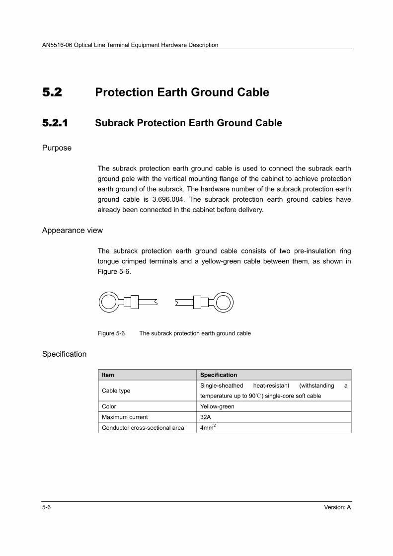
AN5516-06 Optical Line Terminal Equipment Hardware Description
5-6 Version: A
5.2 Protection Earth Ground Cable
5.2.1 Subrack Protection Earth Ground Cable
Purpose
The subrack protection earth ground cable is used to connect the subrack earth
ground pole with the vertical mounting flange of the cabinet to achieve protection
earth ground of the subrack. The hardware number of the subrack protection earth
ground cable is 3.696.084. The subrack protection earth ground cables have
already been connected in the cabinet before delivery.
Appearance view
The subrack protection earth ground cable consists of two pre-insulation ring
tongue crimped terminals and a yellow-green cable between them, as shown in
Figure 5-6.
Figure 5-6 The subrack protection earth ground cable
Specification
Item Specification
Cable type Single-sheathed heat-resistant (withstanding a
temperature up to 90 ) single -core soft cable
Color Yellow-green
Maximum current 32A
Conductor cross-sectional area 4mm2

5 Cable and Connector
Version: A 5-7
5.2.2 Cabinet Protection Earth Ground Cable
Purpose
The cabinet protection earth ground cable is used to connect the protection earth
ground of the PDP with the cabinet earth ground point. Its hardware number is
408000018R1A. The copper tube uninsulated terminal (which is connected to the
PDP) of the cabinet protection earth ground cable has already been connected to
the PE inside terminal of the PDP before delivery.
Appearance view
The cabinet protection earth ground cable consists of a M6 copper tube
uninsulated terminal (which is connected to the PDP), a M6 pre-insulated ring
tongue crimped terminal (which is connected to the cabinet) and a yellow-green
cable between them, as shown in Figure 5-7.
Figure 5-7 The cabinet protection earth ground cable
Specification
Item Specification
Cable type Single-sheathed heat-resistant (withstanding a
temperature up to 90 ) single -core soft cable
Color Yellow-green
Maximum current 40A
Conductor cross-sectional area 2×6mm2

AN5516-06 Optical Line Terminal Equipment Hardware Description
5-8 Version: A
5.3 Alarm Cable
5.3.1 Alarm Cable for the Head of Row Cabinet
Purpose
The alarm cable for the head of row cabinet is used to connect the PDP and the
head of row cabinet and output the equipment alarm signal from the cabinet to the
head of row cabinet. Its hardware number is 3.695.135R1A.
Appearance view
The alarm cable for the head of row cabinet has a three-conductor D-type
connector on one end and three wires on the other end, as illustrated in Figure 5-8.
Figure 5-8 The alarm cable for the head of row cabinet
Specification
Item Specification
Cable type AVVR
Color Brown, black, blue
Maximum current 3A
Conductor cross-sectional area 3×0.5 mm2

5 Cable and Connector
Version: A 5-9
5.3.2 Subrack Alarm Cable
Purpose
The subrack alarm cable connects the CIO card of the subrack with the PDP, and
outputs the subrack alarm to the PDP. Its hardware number is 3.695.095R4A. The
subrack alarm cables have already been connected in the cabinet before delivery.
Appearance view
The subrack alarm cable is universal straight-through network cable, both ends of
which are RJ-45 connectors, as shown in Figure 5-9.
Figure 5-9 The subrack alarm cable
Specification
Item Specification
Cable type CAT-5 twisted pair
Connector (X1/X2) type RJ-45
Number of cores 8
Conductor diameter AWG 24
Breakdown voltage 2000V

AN5516-06 Optical Line Terminal Equipment Hardware Description
5-10 Version: A
5.4 Fiber Jumper
Purpose
The fiber jumper is used to connect the optical interface of the card and the ODF.
The purpose of the fiber jumper varies depending on the interface type as shown in
Table 5-1.
Table 5-1 Purposes of fiber jumpers
Relevant Card Interface Purpose
HU1A/HU2A/GU6F SFP/XFP, GE/XG, GE Provides GE and 10 GE optical channels to
connect the IP network.
C155A STM-1 Provides STM-1 optical channel to connect
the transmission network.
EC4B 1-4 Used in the EPON downlink channel to
connect remote ONUs. EC8B 1-8
GC4B 1-4 Used in the EPON downlink channel to
connect remote ONUs. GC8B 1-8
Appearance view
The AN5516-06 uses the LC / PC and SC / PC fiber jumpers. Their connectors are
illustrated in Figure 5-10 and Figure 5-11 respectively.

5 Cable and Connector
Version: A 5-11
Figure 5-10 The LC / PC optical fiber connector
Figure 5-11 The SC / PC optical fiber connector
The corresponding relationship between the AN5516-06 cards and the fiber jumper
is shown in Table 5-2.
Table 5-2 The corresponding relationship between the card and the fiber jumper
Card Interface Fiber Jumper
C155A STM-1 LC / PC
EC4B 1-4 SC / PC
EC8B 1-8 SC / PC
GC4B 1-4 SC / PC
GC8B 1-8 SC / PC
HU1A XFP/SFP LC / PC
HU2A XG/GE LC / PC
GU6F GE LC/PC

AN5516-06 Optical Line Terminal Equipment Hardware Description
5-12 Version: A
5.5 Coaxial E1 Cable
Purpose
A coaxial E1 cable carries eight E1 signals. Each CE1B card has four E1 interfaces,
which supports the receiving and transmitting of 32 E1 signals. The coaxial E1
cable is mainly used to connect the E1 interfaces of the CE1B card and the MDF.
The coaxial E1 cable includes 75Ω and 120Ω coaxial cables with regard to
impedance. The AN5516-06 uses the 75Ω E1 cable, the hardware number of which
is 3.695.442R2A.
Appearance view
The end of the E1 cable connected with the CE1B card is DB-44P type plug, and
the end connected with the MDF is composed of bare wires. Figure 5-12 illustrates
the appearance of the E1 cable.
Figure 5-12 The 75Ω E1 cable
Terminal definition
Figure 5-13 illustrates the numbering of the 44-pin connector’s terminals; Table 5-3
lists the signal description associated with each pin.
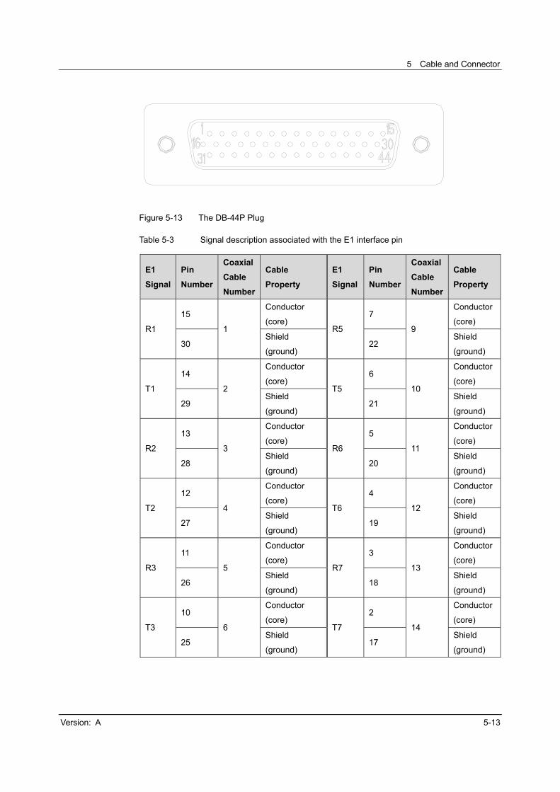
5 Cable and Connector
Version: A 5-13
Figure 5-13 The DB-44P Plug
Table 5-3 Signal description associated with the E1 interface pin
E1
Signal
Pin
Number
Coaxial
Cable
Number
Cable
Property
E1
Signal
Pin
Number
Coaxial
Cable
Number
Cable
Property
R1
15
1
Conductor
(core) R5
7
9
Conductor
(core)
30 Shield
(ground) 22
Shield
(ground)
T1
14
2
Conductor
(core) T5
6
10
Conductor
(core)
29 Shield
(ground) 21
Shield
(ground)
R2
13
3
Conductor
(core) R6
5
11
Conductor
(core)
28 Shield
(ground) 20
Shield
(ground)
T2
12
4
Conductor
(core) T6
4
12
Conductor
(core)
27 Shield
(ground) 19
Shield
(ground)
R3
11
5
Conductor
(core) R7
3
13
Conductor
(core)
26 Shield
(ground) 18
Shield
(ground)
T3
10
6
Conductor
(core) T7
2
14
Conductor
(core)
25 Shield
(ground) 17
Shield
(ground)

AN5516-06 Optical Line Terminal Equipment Hardware Description
5-14 Version: A
E1
Signal
Pin
Number
Coaxial
Cable
Number
Cable
Property
E1
Signal
Pin
Number
Coaxial
Cable
Number
Cable
Property
R4
9
7
Conductor
(core) R8
1
15
Conductor
(core)
24 Shield
(ground) 16
Shield
(ground)
T4
8
8
Conductor
(core) T8
31
16
Conductor
(core)
23 Shield
(ground) 32
Shield
(ground)
Note 1: The copper foil inside the plastic casing is connected to the metal shell of the plug.
Note 2: Ri indicates the i-th input, and Ti indicates the i-th output. The pins not listed in this
table are not used.
Specification
Item Specification
Cable type SYFZ-75-2-1×16
Connector type D-Sub, Type B, 44P plug
Characteristic impedance 75±3Ω
Cable diameter 11.2mm
Number of cores 16
Conductor diameter 2.15mm
DC resistance of the
conductor ≤350Ω/ km
Frequency attenuation
1MHz: ≤2.9 dB/100m
2MHz: ≤3.7dB/100m
10MHz: ≤9.5dB/100m
Capacitance 1KHz: ≤64 pF/m
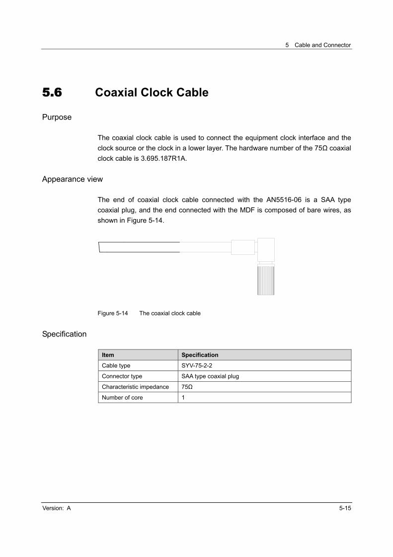
5 Cable and Connector
Version: A 5-15
5.6 Coaxial Clock Cable
Purpose
The coaxial clock cable is used to connect the equipment clock interface and the
clock source or the clock in a lower layer. The hardware number of the 75Ω coaxial
clock cable is 3.695.187R1A.
Appearance view
The end of coaxial clock cable connected with the AN5516-06 is a SAA type
coaxial plug, and the end connected with the MDF is composed of bare wires, as
shown in Figure 5-14.
Figure 5-14 The coaxial clock cable
Specification
Item Specification
Cable type SYV-75-2-2
Connector type SAA type coaxial plug
Characteristic impedance 75Ω
Number of core 1

AN5516-06 Optical Line Terminal Equipment Hardware Description
5-16 Version: A
5.7 Network Cable
Purpose
The network cable is used to connect devices such as the network management
computer and environment monitoring device. Its hardware number is
3.695.095R4A.
Appearance view
Both ends of the network cable are the RJ-45 connectors. The network cable is
illustrated in Figure 5-15.
Figure 5-15 The network cable
Terminal definition
The RJ-45 connector is illustrated in Figure 5-16.
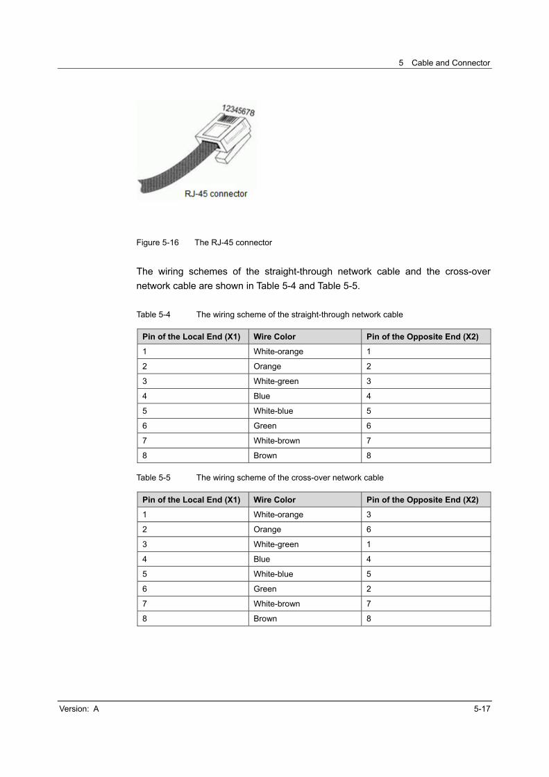
5 Cable and Connector
Version: A 5-17
Figure 5-16 The RJ-45 connector
The wiring schemes of the straight-through network cable and the cross-over
network cable are shown in Table 5-4 and Table 5-5.
Table 5-4 The wiring scheme of the straight-through network cable
Pin of the Local End (X1) Wire Color Pin of the Opposite End (X2)
1 White-orange 1
2 Orange 2
3 White-green 3
4 Blue 4
5 White-blue 5
6 Green 6
7 White-brown 7
8 Brown 8
Table 5-5 The wiring scheme of the cross-over network cable
Pin of the Local End (X1) Wire Color Pin of the Opposite End (X2)
1 White-orange 3
2 Orange 6
3 White-green 1
4 Blue 4
5 White-blue 5
6 Green 2
7 White-brown 7
8 Brown 8

AN5516-06 Optical Line Terminal Equipment Hardware Description
5-18 Version: A
Specification
Item Specification
Cable type CAT-5 twisted pair
Connector (X1/X2) type RJ-45
Number of cores 8
Conductor diameter AWG 24
Breakdown voltage 2000V

5 Cable and Connector
Version: A 5-19
5.8 Serial Port Cable
Purpose
The serial port cable is used to connect the CONSOLE port of the core switch card
or the D port of every card with the serial port of local computer. It is used for the
aforesaid connection only when equipment commissioning is performed. The
hardware number of the serial port cable is 3.695.341R1A.
Appearance view
The end of serial port cable connected with the AN5516-06 is a RJ-45 connector
and the end connected with the network management computer is a DE-9
connector, as illustrated in Figure 5-17.
Figure 5-17 The serial port cable

AN5516-06 Optical Line Terminal Equipment Hardware Description
5-20 Version: A
Terminal definition
The connection relationship of the corresponding pins is shown in Table 5-6.
Table 5-6 Definition of the serial port cable pins
Connected Signal DE-9 Connector Pin RJ45 Connector Pin
Tx 2 3
GND 5 4/5
Rx 3 6
Specification
Item Specification
Cable type CAT-5 twisted pair
Connector type DE-9SJS-X; RJ-45
Number of cores 8
Conductor diameter AWG 24
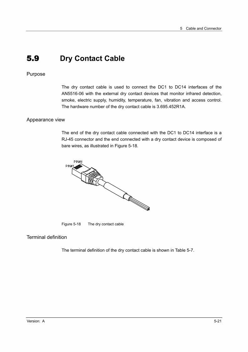
5 Cable and Connector
Version: A 5-21
5.9 Dry Contact Cable
Purpose
The dry contact cable is used to connect the DC1 to DC14 interfaces of the
AN5516-06 with the external dry contact devices that monitor infrared detection,
smoke, electric supply, humidity, temperature, fan, vibration and access control.
The hardware number of the dry contact cable is 3.695.452R1A.
Appearance view
The end of the dry contact cable connected with the DC1 to DC14 interface is a
RJ-45 connector and the end connected with a dry contact device is composed of
bare wires, as illustrated in Figure 5-18.
Figure 5-18 The dry contact cable
Terminal definition
The terminal definition of the dry contact cable is shown in Table 5-7.

AN5516-06 Optical Line Terminal Equipment Hardware Description
5-22 Version: A
Table 5-7 The wiring scheme of the dry contact cable
Terminal Illustration Pin Number Wire Color Opposite End
1 Orange Grounding
2 White-orange Dry contact device 1 level
output end
3 Green Dry contact device 2 level
output end
4 White-green Dry contact device 3 level
output end
5 Blue Dry contact device 4 level
output end
6 White-blue Dry contact device 5 level
output end
7 Brown Dry contact device 6 level
output end
8 White-brown Dry contact device 7 level
output end
Specification
Item Specification
Cable type CAT-5 twisted pair
Connector type RJ-45
Number of cores 8
Conductor diameter AWG 24

Version: A A-1
Appendix A Abbreviation
ACL Access Control List
CATV Cable Antenna Television
CLI Command Line Interface
DHCP Dynamic Host Configuration Protocol
EPON Ethernet Passive Optical Network
GPON Gigabit-capable Passive Optical Network
IGMP Internet Group Management Protocol
IP Internet Protocol
LAN Local Area Network
MGC Media Gateway Controller
MGCP Media Gateway Control Protocol
NGN Next Generation Network
OAM Operation, Administration and Maintenance
ODN Optical Distribution Network
OLT Optical Line Termination
ONU Optical Network Unit
PDP Power Distribution Panel
POTS Plain Old Telephone Service
QoS Quality of Service
SFP Small Form-factor Pluggable Transceiver
SIP Session Initiation Protocol
SNMP Simple Network Management Protocol
TDM Time Division Multiplex
VLAN Virtual Local Area Network
VoIP Voice over Internet Protocol