an2245, freescale solutions for dsp farm aggregation · freescale solutions for dsp farm...
TRANSCRIPT

Freescale SemiconductorApplication Note
AN2245Rev. 1, 11/2004
CONTENTS
1 Generic Gateway Architecture ................................22 Control and Media Packet Flow ..............................42.1 Media Data Path ......................................................42.2 Control Data Path ....................................................63 MSC8101 Device as an Aggregator ........................63.1 Aggregator Performance .........................................73.2 MII Interface ...........................................................73.3 60x-Compatible System Bus–HDI16 Interface ......93.4 Aggregation Function ...........................................104 MPC8260 Device as an Aggregator ......................105 MSC8101 and MPC8260 Compared ....................116 Glossary ................................................................14
Freescale Solutions for DSP Farm AggregationBy David Melles
This application note describes the use of the Freescale StarCore™-based MSC8101 DSP to perform aggregation in an internet protocol (IP) media gateway. 1 In an IP gateway, aggregation is the process of transporting multiple channels of packetized voice and/or fax and/or data (media) to and from the packet-switched network. In a media gateway, aggregation is the process of combining packets from various sources into an aggregate packet stream and routing them to their appropriate destinations. There are many ways to aggregate multiple media channels over a packet-based network. In an IP media gateway, IP encapsulation is used to transport media channels that are in turn encapsulated with some standard IP-based protocols. Our specific scenario is user datagram protocol (UDP) and real-time protocol (RTP) encapsulation of media aggregated over IP. In a generic gateway architecture, there are two distinct steps or types of aggregation:
• Network aggregation. The aggregation of multiple IP datagrams transported over multiple 100 MBit ethernet physical interfaces onto a single (or possibly multiple) gigabit Ethernet physical interface.
• DSP aggregation. The encapsulation or aggregation of multiple UDP/RTP datagrams over IP.
1. Because of their similar physical interfaces, the MPC8260 is a popular alternative to the MSC8101 device in an IP media gateway.
© Freescale Semiconductor, Inc., 2002, 2004. All rights reserved.

Generic Gateway Architecture
DSP aggregation is the topic of this document, in particular the use of the Freescale MSC8101 or MPC8260 devices to perform this aggregation function. The device requires appropriate physical interfaces and sufficient performance/bandwidth to accomplish the necessary routing based upon the scheme chosen. Performance is directly affected by the complexity of the routing protocol and the number of channels serviced. With its field-proven communications interfaces from the communications processor module (CPM) of the MPC8260 and its software programmability, the MSC8101 device is a flexible alternative to conventional hardware aggregation solutions. Its unique combination of RISC CPM and high-performance 300 MHz SC140 core enable it to provide more than the basic aggregator functions. Featuring dual 100 MBit MIIs, UTOPIA Level II with integrated ATM support (AAL0, AAL1, AAL2, AAL5), and E1/T1 and E3/T3 interfaces, the MSC8101 can directly connect to high speed packet-switched and circuit-switched networks.
In addition, the MSC8101 device boasts a quad ALU capable of 1.2 billion instructions per second (equivalent to 3000 RISC MIPs). The SC140 “C friendly” core architecture, highly optimized compiler, and development tool suite make it an ideal platform for terminating protocols from layer 3 and above. In many cases, a simple recompilation of existing MPC8260 C code suffices for porting to the MSC8101. The integration of 512 KB of on-chip SRAM, a 60x-compatible system bus interface, a 16-channel direct memory access (DMA) controller, and programmable interrupt controller (PIC) reduce the overhead of terminating and routing IP or UDP encapsulated media and control. A general-purpose 16-bit host interface (HDI16) easily interconnects with host processors and/or DSPs. With its extremely low power consumption, high performance SC140 core, RISC CPM and rich selection of physical interfaces, the MSC8101 device is an ideal alternative to the MPC8260 as a choice of aggregator. Section 5 compares the rich feature set of both processors.
1 Generic Gateway Architecture A generic media gateway is represented in Figure 1. The functional block marked DSP Aggregator is the block in which the MSC8101/MPC8260 resides in the application discussed in this document. As Figure 1 shows, the generic media gateway architecture is composed of the following functions:
• Network aggregator. The physical interface to the packet network. It routes the media (voice/fax/modem) and Megaco control streams between the packet network and the appropriate internal media gateway components. In a rack-based system, the network aggregator typically resides on an external card. The Freescale C5 network processor is an ideal candidate. The network aggregator transfers control messages to/from the media gateway client and the host processor.
• Host processor. Provides “intelligence” for the media gateway unit, communicating with the rest of the network via an application programming interface (API), which is a media gateway call agent client. The host processor is typically a Freescale MPC8260 CPU running an RTOS to provide socket services for the media gateway control call agent (client) software. It has logical connections for control to the packet network, DSP media aggregator, DSP array and PSTN signaling (not shown). Also, it initializes and maintains necessary routing information for all components.
• DSP array (DSP farm). An array of DSPs (such as the MSC8101 device) that execute the media processing algorithms for voice, fax, and modem and basic packetization/encapsulation for RTP/UDP and Real-Time Control Protocol (RTCP). The DSP farm, DSP media aggregator, and host processor often reside on a single card. The DSP farm has the following logical streams or paths:
— On the PSTN side, media data and signalling are on a separate logical (but possibly common physical) connection.
— Inside the media gateway are separate media data and signaling paths. The signalling is striped/injected by the converter and passed to the host processor by a separate logical and/or physical channel.
Freescale Solutions for DSP Farm Aggregation, Rev. 1
2 Freescale Semiconductor

Generic Gateway Architecture
• DSP Media Aggregator. Concentrates a large number of media (voice, fax or data) channels and transports them between the packet network and DSP farm. An aggregator based on the MSC8101/MPC8260 is essentially an intelligent conduit that physically connects multiple DSPs within the DSP farm or array to the packet and PSTN networks. It also allows network management and call set-up/tear-down information to be filtered from the data stream. The aggregator performs the following functions:
— Terminates packet protocols, such as Ethernet.
— Transfers control messages to/from the DSP array and the host processor.
— Transfers media data to/from the DSP array and the network aggregator.
— Performs housekeeping functions for the DSP array, such as DSP initialization.
Among the features that make the MSC8101 or MPC8260 processors ideally suited to the aggregator function of terminating and distributing packets is the communications processor module (CPM), 60x-compatible bus, very low power consumption, and small footprint (especially the MSC8101). Each DSP within the DSP farm is memory-mapped to the aggregator 60x-compatible system bus. Communication with the control module is achieved via its 16-bit HDI16. The aggregator CPM module, with its two 100 BT Ethernet and UTOPIA interfaces, is used to terminate the packet network with minimal core intervention.
Figure 1. Generic Media Gateway
DSPAggregator
NetworkAggregator
HostProcessor
PSTNConverter
PSTNConverter
DSPArray
MediaGateway Unit
API2
API1
API4
API2DSPAggregator
API2
API1 DSPArray
API1
API3
Downstream (PSTN Domain)
Sideband Signalling
Gateway Control Path
Aggregator Control Path
DSP Control PathDSP Media PathDSP Control Path
Aggregator Aggregator Control Path
Control Path DSP Control Path
DSP Media Path
API1 DSP Message API
API2 Aggregator Message API
API3 Media Gateway Control API
API4 Signalling API
DSP Media DSP Media Path Path
DSP Control Path
DSP Control Path
Freescale Solutions for DSP Farm Aggregation, Rev. 1
Freescale Semiconductor 3

Control and Media Packet Flow
2 Control and Media Packet FlowAs Figure 1 shows, the logical links to the aggregator are as follows:
• Media data path (DSP data path packet-side)
• DSP control path
• Aggregator control path
2.1 Media Data PathSince our architecture is based only on UDP encapsulation, all media packets use UDP, and no IP datagrams containing media are encapsulated within TCP. Figure 2 shows the physical routing for media packets to/from the packet network through to the PSTN physical interface. This routing represents a scenario in which IP media datagrams flow as far as the aggregator. The MAC header and IP header are removed, and the remaining UDP encapsulated media datagrams are transported to the DSP. In another scenario, IP datagrams flow all the way to the DSPs within the DSP array. To minimize the overhead of IP encapsulation and consequently maximize media channel density, we recommend the first scenario.
Figure 2. Media Data Flow
MAC IP UDP RTP DATA
Network Aggregator
MAC IP UDP RTP DATA
DSP Aggregator
RTP DATAUDP
DSP Farm
Data
Out
boun
d
TD
M to
Pac
ket N
etw
ork
Inbo
und
Pac
ket N
etw
ork
to T
DM
MAC Media Access Control Header
IP IPHeader
UDP UDPHeader
RTP RTP Header and Data
Freescale Solutions for DSP Farm Aggregation, Rev. 1
4 Freescale Semiconductor

Control and Media Packet Flow
As Figure 2 shows, the aggregator performs the following tasks:
• Adds and removes the MAC headers.
• Performs IP encapsulation for the outbound or egress media flow.
• Removes the IP header for the inbound or ingress media flow, with the advantage that the bandwidth required between the aggregator and DSP array is reduced.
After the MAC and IP header are removed, the aggregator reads the UDP port destination field of the incoming packet and routes this data to the corresponding DSP based on a simple formula.
To perform appropriate IP encapsulation and add the MAC header, the aggregator maintains a table containing the destination IP address and destination MAC address. The CPM automatically adds the Ethernet CRC. The Ethernet frame containing the IP datagram is sent to the network aggregator for routing. The MSC8101 device has an abundance of on-chip SRAM (512 KB) to buffer incoming and outgoing UDP datagrams efficiently. In an IP gateway, aggregation involves the transportation of multiple channels of packetized voice and/or fax and/or data (media) to and from the packet-switched network. This SRAM prevents the need for external accesses and consequently reduces power consumption. An advantage of routing incoming and outgoing packets based on the UDP address is that a simple yet efficient UDP stack is all that is required to process the packets.
Figure 3. Aggregator UDP Routing
MACIP
DestinationIP
SourceUDP
Source RTP DATAUDP
DestinationUDP
Source RTP DATAUDP
Destination
Ingress
Network AggregatorE
t
h
e
r
n
e
t
E
t
h
e
r
n
e
t
IP Routing
DSP AggregatorE
t
h
e
r
n
e
t
6
0
x
HDI16
DSPArray
MACIP
DestinationIP
SourceUDP
Source RTP DATAUDP
DestinationUDP
Source RTP DATAUDP
Destination
Egress
MAC DestinationDSP Number
IP Destination
Service Type
UDP SourceUDP Destination
Routing Table
Freescale Solutions for DSP Farm Aggregation, Rev. 1
Freescale Semiconductor 5
MSC8101 Device as an Aggregator
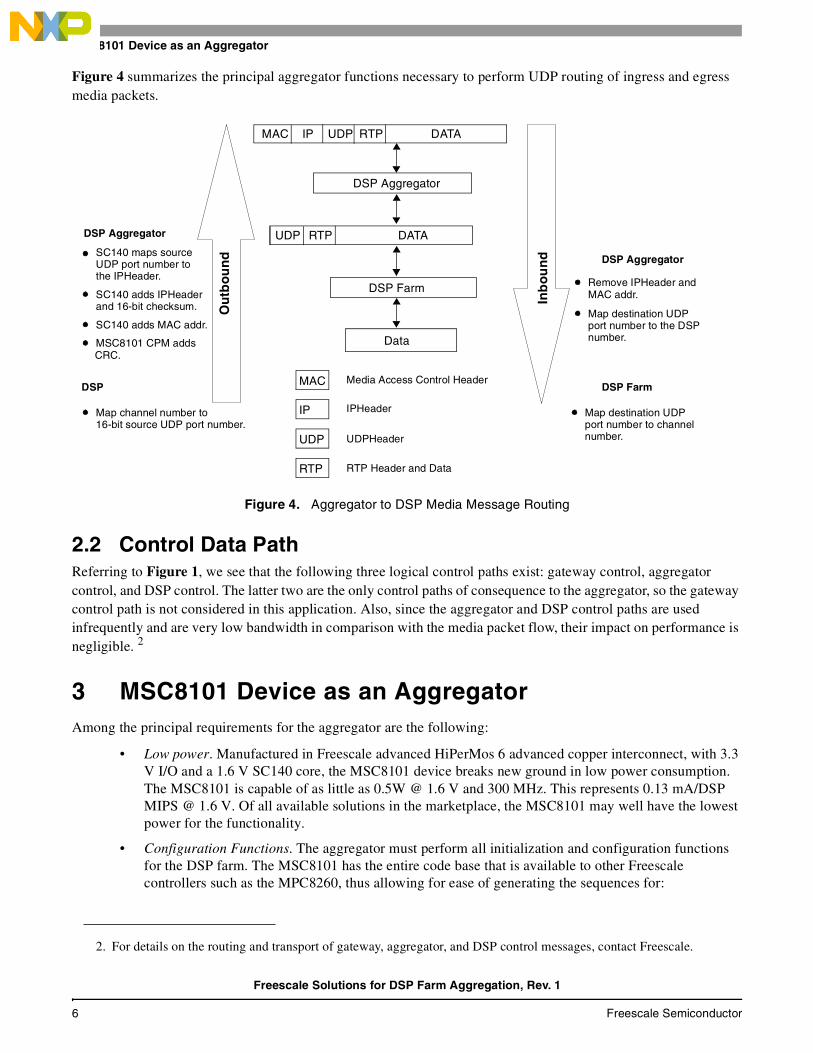
Figure 4 summarizes the principal aggregator functions necessary to perform UDP routing of ingress and egress media packets.
Figure 4. Aggregator to DSP Media Message Routing
2.2 Control Data Path Referring to Figure 1, we see that the following three logical control paths exist: gateway control, aggregator control, and DSP control. The latter two are the only control paths of consequence to the aggregator, so the gateway control path is not considered in this application. Also, since the aggregator and DSP control paths are used infrequently and are very low bandwidth in comparison with the media packet flow, their impact on performance is negligible. 2
3 MSC8101 Device as an Aggregator Among the principal requirements for the aggregator are the following:
• Low power. Manufactured in Freescale advanced HiPerMos 6 advanced copper interconnect, with 3.3 V I/O and a 1.6 V SC140 core, the MSC8101 device breaks new ground in low power consumption. The MSC8101 is capable of as little as 0.5W @ 1.6 V and 300 MHz. This represents 0.13 mA/DSP MIPS @ 1.6 V. Of all available solutions in the marketplace, the MSC8101 may well have the lowest power for the functionality.
• Configuration Functions. The aggregator must perform all initialization and configuration functions for the DSP farm. The MSC8101 has the entire code base that is available to other Freescale controllers such as the MPC8260, thus allowing for ease of generating the sequences for:
2. For details on the routing and transport of gateway, aggregator, and DSP control messages, contact Freescale.
MAC IP UDP RTP DATA
DSP Aggregator
RTP DATAUDP
DSP Farm
Data
Ou
tbo
un
d
Inb
ou
nd
MAC Media Access Control Header
IP IPHeader
UDP UDPHeader
RTP RTP Header and Data
DSP Aggregator
DSP AggregatorSC140 maps sourceUDP port number tothe IPHeader.
SC140 adds IPHeaderand 16-bit checksum.
SC140 adds MAC addr.
MSC8101 CPM addsCRC.
DSP
Map channel number to16-bit source UDP port number.
Remove IPHeader andMAC addr.
Map destination UDPport number to the DSPnumber.
DSP Farm
Map destination UDPport number to channelnumber.
Freescale Solutions for DSP Farm Aggregation, Rev. 1
6 Freescale Semiconductor

MSC8101 Device as an Aggregator
— Booting DSPs
— Heartbeat
— Control and media path conversion (transport in/out of band, independent transport)
— Removing overhead of low-level protocols and buffering from the DSP
• Connectivity. The aggregator must provide the communication paths for control and media (both PSTN and packet). The MSC8101 provides all communication links and protocols required by the application:
— Dual 100Base-T
— 256 channels of 64Kbps TDM (can link gluelessly to an H.110/H.100 bus, synchronous or asynchronous HDLC)
— Up to four E1/T1 interfaces or one E3/T3 interface plus one E1/T1 interface
— General-Purpose Input/Output (GPIO)
— UTOPIA Level II (AAL0, AAL1, AAL2, AAL5) if required later
All of these capabilities are achieved through the MSC8101 CPM. The features are activated and controlled at full speed through programmable microcode, making the MSC8101 a programmable hardware solution.
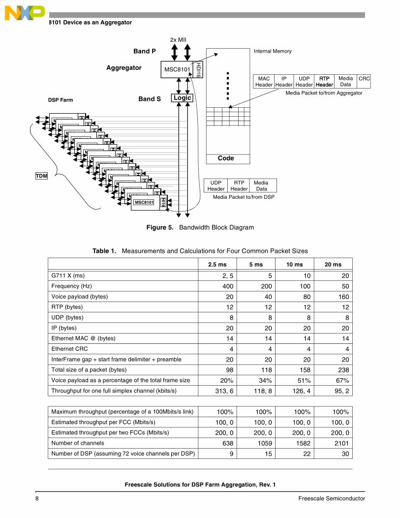
3.1 Aggregator PerformanceIn all aggregator solutions, the system architecture must be analyzed for potential bottlenecks, both in terms of the necessary interface bandwidths and the core performance necessary to support a given channel density. This section considers the MII and HDI16 interface bandwidths, as well as performance of the SC140 core and CPM in a specific scenario: G.711 voiceover IP. Figure 5 shows the ingress data flow, that is, the packet data entering via the MII interface and moving through the MSC8101 aggregator to an MSC8101 device in the DSP farm via the 60x-compatible system bus and the HDI16 host interface.
3.2 MII InterfaceThe packet interface (B and P) has two 100 Mbps media-independent (MII) interfaces. Using the CPM performance tool and taking real-time measurements, we measured the bus occupancy and core performance of the respective areas. Table 1 summarizes the measurements for four common packet sizes. CPM, local bus, and 60x-compatible system bus occupancy is presented as a percentage of the total available.
Freescale Solutions for DSP Farm Aggregation, Rev. 1
Freescale Semiconductor 7
MSC8101 Device as an Aggregator
Figure 5. Bandwidth Block Diagram
Table 1. Measurements and Calculations for Four Common Packet Sizes
2.5 ms 5 ms 10 ms 20 ms
G711 X (ms) 2, 5 5 10 20
Frequency (Hz) 400 200 100 50
Voice payload (bytes) 20 40 80 160
RTP (bytes) 12 12 12 12
UDP (bytes) 8 8 8 8
IP (bytes) 20 20 20 20
Ethernet MAC @ (bytes) 14 14 14 14
Ethernet CRC 4 4 4 4
InterFrame gap + start frame delimiter + preamble 20 20 20 20
Total size of a packet (bytes) 98 118 158 238
Voice payload as a percentage of the total frame size 20% 34% 51% 67%
Throughput for one full simplex channel (kbits/s) 313, 6 118, 8 126, 4 95, 2
Maximum throughput (percentage of a 100Mbits/s link) 100% 100% 100% 100%
Estimated throughput per FCC (Mbits/s) 100, 0 100, 0 100, 0 100, 0
Estimated throughput per two FCCs (Mbits/s) 200, 0 200, 0 200, 0 200, 0
Number of channels 638 1059 1582 2101
Number of DSP (assuming 72 voice channels per DSP) 9 15 22 30
TDM
DSP Farm
MSC8101
HI16
MSC8101
HI16
MSC8101
HI16
MSC8101
HI16
MSC8101
HI16
MSC8101
HI16
MSC8101
HI16
MSC8101
HI16
MSC8101
HI16
MSC8101
HI16
MSC8101
HI16
MSC8101
HI16
MSC8101
HI16
MSC8101
HI16
Logic
HD
I16
MSC8101
2x MII
Band P
Aggregator
Band SMedia Packet to/from Aggregator
Internal Memory
Code
CRCRTPHeader
MACHeader
IPHeader
UDPHeader
Media Packet to/from DSP
Media RTPHeader
UDPHeader Data
RTPHeader
MediaData
Freescale Solutions for DSP Farm Aggregation, Rev. 1
8 Freescale Semiconductor

MSC8101 Device as an Aggregator
These figures are purely for getting the packetized data into and out of the internal MSC8101 SRAM, that is, no servicing is taken into account. The figures are based on the following assumptions:
• 300 MHz MSC8101, 150 MHz CPM, 100 MHz 60x-compatible system bus
• Data buffers in internal SRAM
• Buffer descriptors (BDs) in DPRAM
• Accuracy of the CPM performance tool to within +/- 10%
G.711 encoded voice represents the worst-case scenario because it is the least complex voice codec allowing the highest channel densities but with the least compression and higher consequent bandwidth requirements. Assuming 20 ms frames of G.711 encoded voice, there are 50 frames per second in one direction and 50 frames per second in the opposite direction, for a total of 100 frames per second full duplex. G.711 by definition has a data rate of 64 Kbps. The headers for UDP+RTP and IP+MAC are 20 and 34 bytes, respectively. On the MII packet interface, B and P, there is the additional load of a 32-bit MAC, CRC, interframe gap, start frame delimiter, and Ethernet preamble.
3.3 60x-Compatible System Bus–HDI16 InterfaceFor the 60x–HDI16 interface (Band S), the aggregator has removed the MAC and IP headers, and the remaining UDP and RTP datagrams have been transferred to and from the DSPs. Table 2 shows the channel counts that can be supported, given the specific hardware timing constraints of this interface.
CPM_Perf — CPM occupancy 94, 72% 76, 14% 64, 55% 47, 60%
CPM_Perf — 60x-compatible bus occupancy 3, 05% 2, 45% 1, 70% 1, 13%
CPM_Perf — local bus occupancy 21, 95% 17, 65% 21, 13% 18, 92%
Table 2. MSC8101-Supported Channel Counts
2 ms 5 ms 10 ms 20 ms
G711 X Packet Size (ms) 2, 5 5 10 20
Packet Frequency (Hz) 400 200 100 50
Packet size (Voice Payload + UDP and RTP) (bytes)
40 60 100 180
Full duplex (Tx and Rx) packets/s 800 400 200 100
Necessary bandwidth bytes/s 32000 24000 20000 18000
60x-compatible bus speed (MHz) 100 100 100 100
Bus clocks per 32-byte transfer 90 90 90 90
HDI16 interface bandwidth (MB/s) 35, 56 35, 56 35, 56 35, 56
60x-HDI16 channel capacity (max) 1111 1481 1778 1975
Table 1. Measurements and Calculations for Four Common Packet Sizes (Continued)
2.5 ms 5 ms 10 ms 20 ms
Freescale Solutions for DSP Farm Aggregation, Rev. 1
Freescale Semiconductor 9

MPC8260 Device as an Aggregator
The figures in Table 2 are based on the following assumptions:
• 100 MHz 60x-compatible system bus
• Simple discrete logic interface (contact Freescale for alternative hardware scenarios)
• Transfer of UDP/RTP encapsulated G.711 media only; that is, no control information
The last assumption is not the case in reality since there will be no control messages to be transferred between the aggregator and the DSP farm. In addition, the transfer of media such as G.711 requires some additional protocol or header information that may not be transferred as part of a 32-byte transfer. That is, the use of single-byte transfers may be required. However, the addition of control messages and the extra overhead of additional header information is unlikely to change the channel count drastically.
3.4 Aggregation FunctionUntil now, we have focused primarily on the transfer of packetized data between the packet interface (MII) and the DSP farm (HDI16–60x interface). The two previous sections demonstrate that the bandwidth available on the MII and HDI16 interfaces is sufficient to support a certain channel density dictated largely by the minimum packet size. However, this is not the sole function of the aggregator. The appropriate Layer 4 (UDP) routing of this media and control information is also a function of the aggregator, as discussed in Section 2, Control and Media Packet Flow. This routing function will probably be limited primarily by SC140 core cycles. Among the things affecting channel density are the following:
• Compiler efficiency
• Use of “C” versus hand-optimized or hand-coded Assembly language
• Overall software architecture (architecture-independent versus architecture-specific)
• Appropriate use of interrupts, polling, prioritization, and context switching
• Appropriate use of buffering (single versus double)
All of these issues are currently under investigation and development by Freescale. However, our preliminary results suggest that the MSC8101 device can support a minimum of a DS3 (672 channels). Contact Freescale for further information and code examples.
4 MPC8260 Device as an Aggregator Much of the information in Section 3 also applies to the MPC8260. In addition, the key advantages of the MPC8260 device are its performance and industry-standard acceptance. The MPC8260 integrated communications processor delivers excellent integration of processing power for networking and communications peripherals. It represents an innovative total system solution for high-end communications systems. The MPC8260’s 266 MHz embedded 603e core, powerful memory controller, and enhanced CPM make it a powerful alternative to the MSC8101. In addition, the PowerQUICC IITM family, of which the MPC8260 is but one member, is supported by a strong third-party tools support network from Freescale’s Smart Networks Alliance. The PowerQUICC II has an entire code base that is available and dedicated to a rich array of functions. The MPC8260 provides additional communication links and protocols required by the application over and above that provided by the MSC8101 device:
• Up to three 100 Mbps MII interfaces
• Eight TDM interfaces (E1/T1), of which two.can be interfaced with E3/T3
Freescale Solutions for DSP Farm Aggregation, Rev. 1
10 Freescale Semiconductor

MSC8101 and MPC8260 Compared
• Up to two UTOPIA Level II master/slave ports with multi-PHY
• External 64-bit bus and 32-bit PCI or local bus
The PowerQUICC II family is an industry-standard choice for networking applications such as:
• Remote access concentrators
• Regional office routers
• Cellular infrastructure equipment
• Telecom switching equipment
• Ethernet switches
• E1/T1 to E3/T3 bridges
• LAN to WAN bridges and routers
• XDSL systems
Table 3 summarizes the PowerQUICC II family derivatives and their CPM features.
5 MSC8101 and MPC8260 ComparedTable 4 compares the overall features of the MSC8101 and MPC8260 devices.
Table 3. PowerQUICC IITM Family Derivatives
CPM Feature MPC8255 MPC8260 MPC8264 MPC8265 MPC8266
Serial Communications Controllers (SCCs)
4 4 4 4 4
Fast Serial Communications Controller (FCCs)
2 3 3 3 3
Instruction Cache (KB) 16 16 16 16 16
Data Cache (KB) 16 16 16 16 16
Ethernet (10 Base-T) Up to 4 Up to 4 Up to 4 Up to 4 Up to 4
MII Ethernet (10/100 Base-T) Up to 2 Up to 3 Up to 3 Up to 3 Up to 3
UTOPIA II Ports 1 2 2 2 2
Multi-channel HDLC Up to 128 Up to 256 Up to 256 Up to 256 Up to 256
PCI Interface — — — Yes Yes
IMA Functionality — — Yes — Yes
Table 4. MSC8101 and MPC8260 Features Compared
MSC8101 Features MPC8260 Features
SC140 Core• 1200 DSP MIPS (equivalent to 3000 RISC MIPs) @
300MHz
Power PCTM 603e core (100-266 MHz)• 140.0 MIPS at 100 MHz (Dhrystone 2.1)• 372.0 MIPS at 266 MHz (Dhrystone 2.1)
512 KB Internal SRAM 16 KB data and 16 KB instruction cache
Four 16 bit Fixed Point ALUs Floating-point unit enabled
Enhanced Filter Coprocessor (EFCOP) Common on-chip processor (COP)
Freescale Solutions for DSP Farm Aggregation, Rev. 1
Freescale Semiconductor 11

MSC8101 and MPC8260 Compared
Figure 6 shows the architecture of the MSC8101 device.
High-Performance Communications Processor Module (CPM) with operating frequency up to 150 MHz • Two multi-channel controllers (MCCs), each supporting
128 full-duplex, 64 Kbps, HDLC lines• Three FCCs (of which only two pinned out) supporting:
• Up to 155 Mbps ATM SAR (maximum of one) (AAL0, AAL1, AAL2, AAL5)
• 10/100 Mbps Ethernet (up to two) (IEEE 802.3X with Flow Control)
• HDLC/Transparent (up to T3 rates)• UTOPIA level-2 master/slave port, with multi-PHY
support (maximum of one)• Two MII Interfaces • Four TDM interfaces (T1/E1), one TDM ports can be
glueless to T3/E3
High-Performance CPM with operating frequency up to 133, 166, or 200 MHz• Two MCCs, each supporting 128 full-duplex, 64 Kbps,
HDLC lines• Three FCCs supporting:
• Up to 155 Mbps ATM SAR (maximum of two) (AAL0, AAL1, AAL2, AAL5)
• 10/100 Mbps Ethernet (up to three) (IEEE 802.3X with Flow Control)
• 45 Mbps HDLC/Transparent (up to three)• Two UTOPIA level-2 master/slave ports, both with multi-
PHY support• Three MII Interfaces • Eight TDM interfaces (E1/T1); two TDM ports can be
glueless to E3/T3
16-Channel Direct Memory Access (DMA) controller Virtual DMA functionality
16-bit HDI16 host interface PCI up to 66 MHz (subsequent versions)
60x-compatible system bus @ 100 MHz Two bus architectures: one 64-bit 60x bus and one 32-bit PCI or local bus
HiPerMos 6 - advanced copper interconnect
Very low power dissipation: 0.5W @ 1.6V 266 MHz power consumption: 2.5 W
3.3 V I/O, 1.6V Core
0.13 mA/DSP MIPS @ 1.6 V. 1.8V or 2.0 V internal and 3.3V I/O
IEEE 1149.1 JTAG test access port IEEE 1149.1 JTAG test access port
Enhanced On-Chip Emulation (EOnCE)™
Small footprint package:• 17 mm x 17 mm Flip Chip Plastic Ball Grid Array
(FCPBGA) 332-pin, 0.8 mm ball pitch
480 TBGA package (37.5 mm x 37.5 m
Table 4. MSC8101 and MPC8260 Features Compared (Continued)
MSC8101 Features MPC8260 Features
Freescale Solutions for DSP Farm Aggregation, Rev. 1
12 Freescale Semiconductor

MSC8101 and MPC8260 Compared
Figure 6. MSC8101 Architecture Block Diagram
The MPC8260 PowerQUICC II™ is a versatile communications processor that integrates a high-performance RISC microprocessor, a flexible system integration unit, and many communications peripheral controllers that can be used in a variety of applications, particularly in communications and networking systems (see Figure 7).
UTOPIA 8
OtherPeripherals
MII
TDMs
CPM
‘MC
C’ /
UA
RT
/ H
DLC
/ Tr
ansp
aren
t /E
net /
Fas
tEne
t / A
TM
/ S
CC
s
PITSystem Protection
Reset ControlClock Control
SIU
8/16-bitHost
SC140
PowerManagement Clock/PLL 64-bit XA Data Bus
128-bit P-Bus
64-bit XB Data Bus
Extended Core
Interface
64-bit
Core
•••
Ser
ial I
nter
face
and
TS
A
3 x FCC
4 x SCC
SPI
I2C
2 x MCC
2 x SMC
Interrupt
Timers
Baud-Rate
Parallel I/O
Generators
Controller
Dual PortedRAM
ProgramSequencer
AddressRegister
File
Data ALURegister
File
AddressALU
DataALU
64/32-bitSystemBus
Interrupts
EOnCE™JTAG
Local Bus
2 x SDMA
RISC
Interface
DMAEngine
Bridge
Q2PPCBridge
BootROM
SRAM512 KB
128-bit QBus
MEMC
L1 Interface
HDI16
MEMC
{
PIC
EFCOP
SIC_EXT
SICInterrupts
64-Bit System Bus
Freescale Solutions for DSP Farm Aggregation, Rev. 1
Freescale Semiconductor 13

Glossary
Figure 7. MPC8260 Architecture Block Diagram
6 GlossaryApplication Programming Interface (API). The method prescribed by a computer operating system or by an
application program by which a programmer writing an application program can make requests of the operating system or another application.
Communications Processor Module (CPM). An embedded 32-bit RISC controller dedicated to handle lower physical layer tasks such as terminating Ethernet, ATM, TDM, and so on.
Datagram. To quote the Internet’s RFC 1594, “a self-contained, independent entity of data carrying sufficient information to be routed from the source to the destination computer without reliance on earlier exchanges between this source and destination computer and the transporting network.”
Host Interface (HDI16). A 16-bit wide full duplex, double buffered, parallel port for communication with an external host processor.
Host Processor (host). Handles the registration and management of resources at the media gateway. The host may have the ability to authorize resource usage based on local policy. For signaling transport purposes, the Host serves as a possible termination and origination point for SCN application protocols.
Internet Protocol (IP). A protocol for transmitting blocks of data (datagrams) between interconnected systems over a packet-switched communications network.
16 KB
G2 Core
I-Cache
I-MMU
16 KBD-Cache
D-MMU
Communication Processor Module (CPM)
Timers
Parallel I/O
Baud-RateGenerators
24 KB
32-bit RISC Microcontrollerand Program ROM
SerialDMAs
2 VirtualIDMAs
Bridge
Memory Controller
Clock Counter
System Functions
System Interface Unit (SIU)
Local Bus32 bits, up to 66 MHz
MCC1 MCC2 FCC1 FCC2 FCC3 SCC1 SCC2 SCC3 SCC4 SMC1 SMC2 SPI I2C
Serial Interface
3 MII 2 UTOPIA PortsPorts
60x Bus
Dual-Port RAMInterrupt Controller
Time Slot Assigner
8 TDM Ports Non-MultiplexedI/O
60x-to-Local
Bus Interface Unit
Freescale Solutions for DSP Farm Aggregation, Rev. 1
14 Freescale Semiconductor

Glossary
Media Access Control (MAC). In the Open Systems Interconnection (OSI) model of communication, the Media Access Control layer is one of two sublayers of the data link control layer and is concerned with sharing the physical connection to the network among several computers. Each computer has its own unique MAC address. Ethernet is an example of a protocol that works at the media access control layer level.
Media Access Control Address (MAC) Address. On a local area network (LAN) or other network, the MAC address is the computer’s unique hardware number. On an Ethernet LAN, it is the same as the Ethernet address. When a computer (host) is connected to the Internet, a correspondence table relates the IP address to the computer’s physical (MAC) address on the LAN. The MAC address is used by the Media Access Control sublayer of the Data-Link Layer (DLC) layer of telecommunication protocol. There is a different MAC sublayer for each physical device type. The other sublayer level in the DLC layer is the Logical Link Control sublayer.
Media Gateway (MG). Terminates SCN media streams and “packetizes” the media data, if it is not already packetized, and delivers the packetized traffic to the packet network. It performs these functions in reverse order for media streams flowing from the packet network to the SCN.
Media Gateway Unit (MGU). A physical entity containing the MG function. It may contain other functions, especially an SG function for handling facility-associated signaling.
Public Switched Telephone Network (PSTN). Refers to the world’s collection of interconnected voice-oriented public telephone networks, both commercial and government-owned. It is also referred to as the Plain Old Telephone Service. Today, it is almost entirely digital in technology except for the final link from the central (local) telephone office to the user.
Real-Time Operating System (RTOS). An operating system that guarantees a certain capability within a specified time constraint.
Real-Time Protocol (RTP). A protocol that provides end-to-end network transport functions suitable for applications transmitting real-time data such as audio, video, or simulation data. See RFC1889 for the official specification.
Switched Circuit Network (SCN). A type of network in which a physical path is obtained for and dedicated to a single connection between two end-points in the network for the duration of the connection. Ordinary voice phone service is circuit-switched. The telephone company reserves a specific physical path to the number called for the duration of a call. During that time, no one else can use the physical lines involved.
Time Division Multiplexing (TDM). A scheme in which numerous signals are combined for transmission on a single communications line or channel. Each signal is broken up into many segments, each with a very short duration.
User Datagram Protocol (UDP). A simple, datagram-oriented transport layer protocol. See RFC 768 for the official specification.
Freescale Solutions for DSP Farm Aggregation, Rev. 1
Freescale Semiconductor 15

AN2245
Information in this document is provided solely to enable system and software implementers to use Freescale Semiconductor products. There are no express or implied copyright licenses granted hereunder to design or fabricate any integrated circuits or integrated circuits based on the information in this document.
Freescale Semiconductor reserves the right to make changes without further notice to any products herein. Freescale Semiconductor makes no warranty, representation or guarantee regarding the suitability of its products for any particular purpose, nor does Freescale Semiconductor assume any liability arising out of the application or use of any product or circuit, and specifically disclaims any and all liability, including without limitation consequential or incidental damages. “Typical” parameters which may be provided in Freescale Semiconductor data sheets and/or specifications can and do vary in different applications and actual performance may vary over time. All operating parameters, including “Typicals” must be validated for each customer application by customer’s technical experts. Freescale Semiconductor does not convey any license under its patent rights nor the rights of others. Freescale Semiconductor products are not designed, intended, or authorized for use as components in systems intended for surgical implant into the body, or other applications intended to support or sustain life, or for any other application in which the failure of the Freescale Semiconductor product could create a situation where personal injury or death may occur. Should Buyer purchase or use Freescale Semiconductor products for any such unintended or unauthorized application, Buyer shall indemnify and hold Freescale Semiconductor and its officers, employees, subsidiaries, affiliates, and distributors harmless against all claims, costs, damages, and expenses, and reasonable attorney fees arising out of, directly or indirectly, any claim of personal injury or death associated with such unintended or unauthorized use, even if such claim alleges that Freescale Semiconductor was negligent regarding the design or manufacture of the part.
Freescale™ and the Freescale logo are trademarks of Freescale Semiconductor, Inc. StarCore is a trademark of StarCore LLC. All other product or service names are the property of their respective owners.
© Freescale Semiconductor, Inc. 2004.
How to Reach Us:Home Page:www.freescale.com
E-mail:[email protected]
USA/Europe or Locations not listed:Freescale Semiconductor Technical Information Center, CH3701300 N. Alma School RoadChandler, Arizona 85224+1-800-521-6274 or [email protected]
Europe, Middle East, and Africa:Freescale Halbleiter Deutschland GMBHTechnical Information CenterSchatzbogen 781829 München, Germany+44 1296 380 456 (English)+46 8 52200080 (English)+49 89 92103 559 (German)+33 1 69 35 48 48 (French)[email protected]
Japan:Freescale Semiconductor Japan Ltd. HeadquartersARCO Tower 15F1-8-1, Shimo-Meguro, Meguro-ku,Tokyo 153-0064, Japan0120 191014 or +81 3 5437 [email protected]
Asia/Pacific:Freescale Semiconductor Hong Kong Ltd.Technical Information Center2 Dai King StreetTai Po Industrial EstateTai Po, N.T. Hong Kong+800 2666 8080
For Literature Requests Only:Freescale Semiconductor Literature Distribution CenterP.O. Box 5405Denver, Colorado 802171-800-441-2447 or 303-675-2140Fax: [email protected]
Rev. 111/2004