an online heat generation estimation method for lithium
TRANSCRIPT
Contents lists available at ScienceDirect
Applied Energy
journal homepage: www.elsevier.com/locate/apenergy
An online heat generation estimation method for lithium-ion batteries usingdual-temperature measurements
Jianan Zhanga,b,c, Xiao-Guang Yangb, Fengchun Suna,c, Zhenpo Wanga,c,⁎, Chao-Yang Wangb,⁎
aNational Engineering Laboratory for Electric Vehicles, Beijing Institute of Technology, Beijing 100081, Chinab Electrochemical Engine Center (ECEC) and Department of Mechanical Engineering, The Pennsylvania State University, University Park, PA 16802, USAc Collaborative Innovation Center for Electric Vehicles in Beijing, Beijing 100081, China
H I G H L I G H T S
• A straightforward and accurate Li-ionbattery heat generation estimationmethod is presented for online usage.
• The method is of strong robustnessagainst changes in ambient tempera-tures and convection conditions.
• Heat generation inside a battery cellregardless of sources are covered.
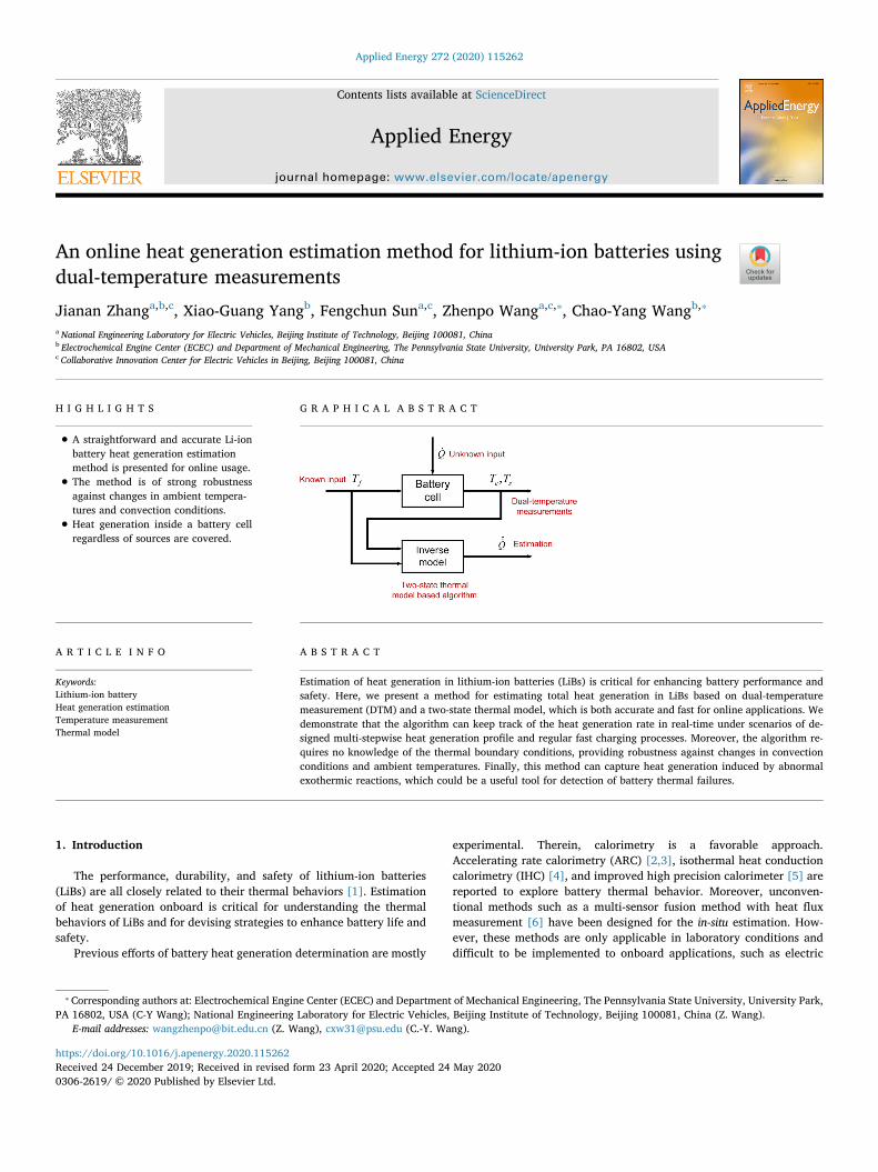
G R A P H I C A L A B S T R A C T
A R T I C L E I N F O
Keywords:Lithium-ion batteryHeat generation estimationTemperature measurementThermal model
A B S T R A C T
Estimation of heat generation in lithium-ion batteries (LiBs) is critical for enhancing battery performance andsafety. Here, we present a method for estimating total heat generation in LiBs based on dual-temperaturemeasurement (DTM) and a two-state thermal model, which is both accurate and fast for online applications. Wedemonstrate that the algorithm can keep track of the heat generation rate in real-time under scenarios of de-signed multi-stepwise heat generation profile and regular fast charging processes. Moreover, the algorithm re-quires no knowledge of the thermal boundary conditions, providing robustness against changes in convectionconditions and ambient temperatures. Finally, this method can capture heat generation induced by abnormalexothermic reactions, which could be a useful tool for detection of battery thermal failures.
1. Introduction
The performance, durability, and safety of lithium-ion batteries(LiBs) are all closely related to their thermal behaviors [1]. Estimationof heat generation onboard is critical for understanding the thermalbehaviors of LiBs and for devising strategies to enhance battery life andsafety.
Previous efforts of battery heat generation determination are mostly
experimental. Therein, calorimetry is a favorable approach.Accelerating rate calorimetry (ARC) [2,3], isothermal heat conductioncalorimetry (IHC) [4], and improved high precision calorimeter [5] arereported to explore battery thermal behavior. Moreover, unconven-tional methods such as a multi-sensor fusion method with heat fluxmeasurement [6] have been designed for the in-situ estimation. How-ever, these methods are only applicable in laboratory conditions anddifficult to be implemented to onboard applications, such as electric
https://doi.org/10.1016/j.apenergy.2020.115262Received 24 December 2019; Received in revised form 23 April 2020; Accepted 24 May 2020
⁎ Corresponding authors at: Electrochemical Engine Center (ECEC) and Department of Mechanical Engineering, The Pennsylvania State University, University Park,PA 16802, USA (C-Y Wang); National Engineering Laboratory for Electric Vehicles, Beijing Institute of Technology, Beijing 100081, China (Z. Wang).
E-mail addresses: [email protected] (Z. Wang), [email protected] (C.-Y. Wang).
Applied Energy 272 (2020) 115262
0306-2619/ © 2020 Published by Elsevier Ltd.
T

vehicles (EVs).On the other hand, in order to capture heat generation, modeling
methods have been used in the existing literature. The electrochemical-thermal (ECT) models based on physical principles can calculate heatgeneration, including kinetic heat, reversible heat, joule heat, etc. [7,8]with excellent accuracy. However, they require high computationalcosts and are difficult to be implemented in real-world applications.
Therefore, simplified methods are utilized in online situations.Constant heat generation rate [9], curve fitting technique [10], andJoule’s Law [11] are extensively used in engineering practices. Never-theless, these approaches can be over-simplified and lead to significanterrors or a lack of generalization capabilities. Beyond those, the mostused method to date is the simplified equation deduced by Bernardi [2],which calculates heat generation via I*(OCV-Vcell), where I is current,OCV is open-circuit voltage, and Vcell is cell voltage. However, due tothe necessity of voltage, current, open circuit voltage (OCV), and stateof charge (SOC), the high estimation accuracy is required for theseprimary parameters, and significant errors could occur in practice. Inaddition, the modeling methods consider heat generation from knownelectrochemical sources via given electrochemical processes or equa-tions. Hence, unmodeled heat generation behavior or abnormal heatgeneration, such as internal short circuits and exothermic side reac-tions, are unable to be accounted for.
To resolve the drawbacks of existing experimental and modelingapproaches and to address the convenience and accuracy required ofonboard applications, better understanding of battery thermal behavior
is necessary. Also, as automotive battery cells become large in size,there is usually a significant temperature gradient inside a cell [12].Therefore, obtaining internal temperatures become necessary. Methodssuch as impedance-based estimation by its temperature dependency[13], model-based estimation algorithm with Kalman filter techniques[14], or direct measurement using embedded thermal couples [15]have been widely reported. However, gaining knowledge of internaltemperature is rather limited, and most of the methods mentionedabove are impossible for use in onboard applications.
In this paper, we present a direct and accurate method to estimatebattery heat generation in real-time from a heat transfer perspective. Inorder to handle the problem of temperature gradient inside a cell, adual-temperature measurement (DTM) structure is proposed. It is mo-tivated by the self-heating lithium-ion battery (SHLB) [16] and canmeasure battery surface and core temperatures simultaneously. TheSHLB has a micron-thin nickel (Ni) foil embedded in the center of a cell,whose resistance is linear with respect to temperature and can thusserve as an internal temperature sensor (ITS). More details about theSHLB structure is given in Section 3.1. Afterward, the temperaturesmeasured by DTM are incorporated into a two-state thermal model toestimate heat generation, which achieves a good balance between ac-curacy and computational cost. The heat generation estimation algo-rithm is developed by utilizing discretization and inverse model tech-niques. It can be observed that the proposed algorithm requires no priorknowledge of thermal boundary conditions and also exhibits strongrobustness against changes in thermal boundary conditions. Moreover,
Nomenclature
Electrochemical-thermal model
Ae electrode area (m2)c lithium concentration (mol m−3)cp specific heat (J kg−1 K−1)D diffusivity (m2 s−1)F Faraday constant (96487 C mol−1)h convective heat transfer coefficient (W m−2 K−1)j volumetric current density (A m−3)L sum of the anode, separator and cathode thicknesses (m)Q total heat generation rate (W)Qapp applied additional heat generation rate (W)Qele electrochemical heat generation rate (W)r coordinate in the radial direction (m)t time (s)+t transference numberT temperature (K)U open circuit potential (V)x coordinate in the electrode thickness direction (m)z coordinate in the cell thickness direction (m)
Greek
ε volume fractionδ cell thickness (m)κ thermal conductivity (W m−1 K−1)κeff effective ionic conductivity (S m−1)κD
eff effective diffusional ionic conductivity (S m−1)ρ density (kg m−3)σeff effective electronic conductivity (S m−1)ϕ phase potential (V)
Superscript and subscripts
avg average
e electrolyte phases solid phase
Two-state thermal model
Cc heat capacity of the battery cell core component (J K−1)Cs heat capacity of the battery cell surface component
(J K−1)Q total heat generation rate (W)
Q estimated total heat generation rate (W)Rc thermal resistance between the core and the surface
component (K W−1)Ru convective thermal resistance between the surface com-
ponent and ambient (K W−1)tΔ sampling interval
Tc core temperature (K)Ts surface temperature (K)
Superscript and subscripts
k kth time step
List of abbreviations
ACT activationDTM dual-temperature measurementECT electrochemical-thermalEV electric vehicleFUDS Federal Urban Driving ScheduleITS internal temperature sensorOCV open circuit voltagePSO particle swarm optimizationRMSE root mean squared errorSHLB self-heating lithium-ion batterySOC state of charge
J. Zhang, et al. Applied Energy 272 (2020) 115262
2

the total heat generation of a battery cell is obtained. Thus, abnormalheat generation can be detected from the estimation results, which isvaluable for early detection of thermal faults and improved batterysafety.
In order to demonstrate the accuracy of the presented method, aseries of simulations are conducted through an experimentally cali-brated ECT coupled model under conditions of a hypothetically de-signed multi-stepwise heat generation profile and heat generation infast charging cases. The heat generation rates resulting from the ECTmodel are taken as theoretical values and are compared with the al-gorithm estimation values. In addition, the effects of heat convectionconditions and cell thicknesses are explored.
The remainder of this paper is organized as follows: the ECT mod-eling is presented in Section 2. Section 3 introduces the present heatgeneration estimation scheme. Section 4 shows the simulation resultsand algorithm evaluation. Section 5 concludes the paper.
2. Electrochemical-thermal model
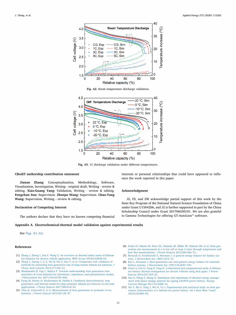
In this section, an electrochemical-thermal (ECT) model is devel-oped, which will be used to generate necessary data for parameteridentification of the two-state thermal model and will be employed forevaluation of estimation results. The ECT model is established in GT-AutoLion™, a commercial software package for multi-disciplinary li-thium-ion battery and system simulation and analysis [17]. Moreover,the ECT model is validated against experimental results, which areshown in the Appendix A. Charge/discharge with different C-rates andtemperature tests are validated respectively in Figs. A1–A3.
In this research, the modeled lithium-ion battery is a 10Ah pouchcell, with electrode chemistry of LiNi0.6Mn0.2Co0.2O2 (NMC622)/Graphite and the electrolyte of 1 M LiPF6 in 3:7 (wt%/wt%) EC/EMCwith 2% wt VC. The dimension of the cell is 130 mm * 75 mm * 10 mm(length * width * thickness).
2.1. Electrochemical model
By adopting the fully coupled electrochemical model of Gu andWang [18], the conservation equations are given by the following Eqs.(1)–(4):
Charge conservation in solid electrodes:
∇ ∇ =σ ϕ j·( )seff
s (1)
where σseff is the effective electronic conductivity of solid phase, ϕs is the
electric potential in solid phase, and j is the volumetric current density.Charge conservation in electrolyte:
∇ ∇ + ∇ ∇ = −κ ϕ κ c j·( ) ·( ln )effe D
effe (2)
where κeff is the effective ionic conductivity of electrolyte, ϕe is theelectric potential in electrolyte, κD
eff is the effective diffusional ionicconductivity of electrolyte, ce is the species concentration in electrolyte.
Species conservation in electrolyte:
∂∂
= ∇ ∇ + − +ε ct
D c tF
j·( ) 1eeeff
e (3)
in which ε is the volume fraction, Deeff is the effective electrolyte dif-
fusivity, +t is the transference number, F is the Faraday constant.Species conservation in active material particles:
∂∂
= ∂∂
⎛⎝
∂∂
⎞⎠
ct r r
D r cr
1ss
s2
2(4)
in which cs is the species concentration in solid phase and Ds is the solidphase diffusivity, r is the coordinate in the particle radial direction, t isthe time.
Detailed explanations of the above equations can also be found inthe literature [19,20] and therefore are not repeated here. Parametersof these equations are adopted from the materials database of GT-
AutoLion™.
2.2. Thermal model
For depicting the heat transfer process of a battery cell, a 1Dthermal model is adopted [21]. Governing equations for the thermalfield are given below.
Thermal energy conservation:
∂∂
= ∇ ∇ +ρc Tt
κ T Q·( ) p (5)
where ρ, cp and κ are density, specific heat capacity, and thermalconductivity of the cell, respectively, Q is the heat generation term.Thermal properties of the pouch battery cell, such as specific heat ca-pacity and thermal conductivity are employed from the literature [22].
Thermal boundary conditions:
∂∂
=Tz
t(0, ) 0(6)
∂∂
= −∞Tz
δ t hκ
T T δ t( , ) [ ( , )](7)
where t stands for time, and ∈z δ[0, ] is the spatial coordinate in thebattery cell thickness direction. The origin of the coordinate system liesin the middle of the cell thickness and δ represents half of the cellthickness. h is the convective heat transfer coefficient.
Heat generation from electrochemical effects is given as [18]:
∫ ⎜ ⎟= ⎡
⎣⎢
⎛⎝
∂∂
⎞⎠
+ − − + ∇ ∇ + ∇ ∇
+ ∇ ∇ ⎤
⎦⎥
Q
A j T UT
j ϕ ϕ U σ ϕ ϕ κ ϕ ϕ
κ c ϕ dx
( ) · ·
ln
ele
eL
s e seff
s seff
e e
Deff
e e
0 avgavg
(8)
where Ae is the electrode area, L is the sum of the anode, separator, andcathode thickness, Tavg is the average temperature of the battery cell.
The ∂∂( )j T U
Tavg avgterm shows the reversible heat, the − −j ϕ ϕ U( )s e term
represents kinetic heat, the ∇ ∇σ ϕ ϕ·seff
s s, ∇ ∇κ ϕ ϕ·effe e and ∇ ∇κ c ϕlnD
effe e
term indicates joule heat from electronic resistance, ionic resistance andconcentration overpotential, respectively. More detailed explanationsfor the above heat generation equation can also be referred to Ref. [19].
2.3. Treatment of performing extra given heat generation rate
Battery normal heat generation is a result of the loading currentduring operation. However, the amplitude of the electrochemical heatgeneration rate also depends on cell dimensions, SOCs, and even celltemperatures. In order to provide an unbiased comparison and discus-sion between different case studies, a consistently designed heat gen-eration profile is needed, and an extra given heat generation rate Qapp isapplied to compose the total heat generation of the battery cell.Therefore, the total heat generation rate is given by:
= +Q Q Q ele app (9)
Note that when battery cell has no current flowing through, =Q 0ele ,and hence =Q Q app.
3. Heat generation estimation scheme
3.1. Dual-temperature measurement method
In this subsection, a dual-temperature measurement (DTM) methodis presented, which provides necessary core and surface temperatureinformation for estimation of the battery heat generation. DTM is im-plemented via the SHLB structure elaborated earlier [16].
J. Zhang, et al. Applied Energy 272 (2020) 115262
3
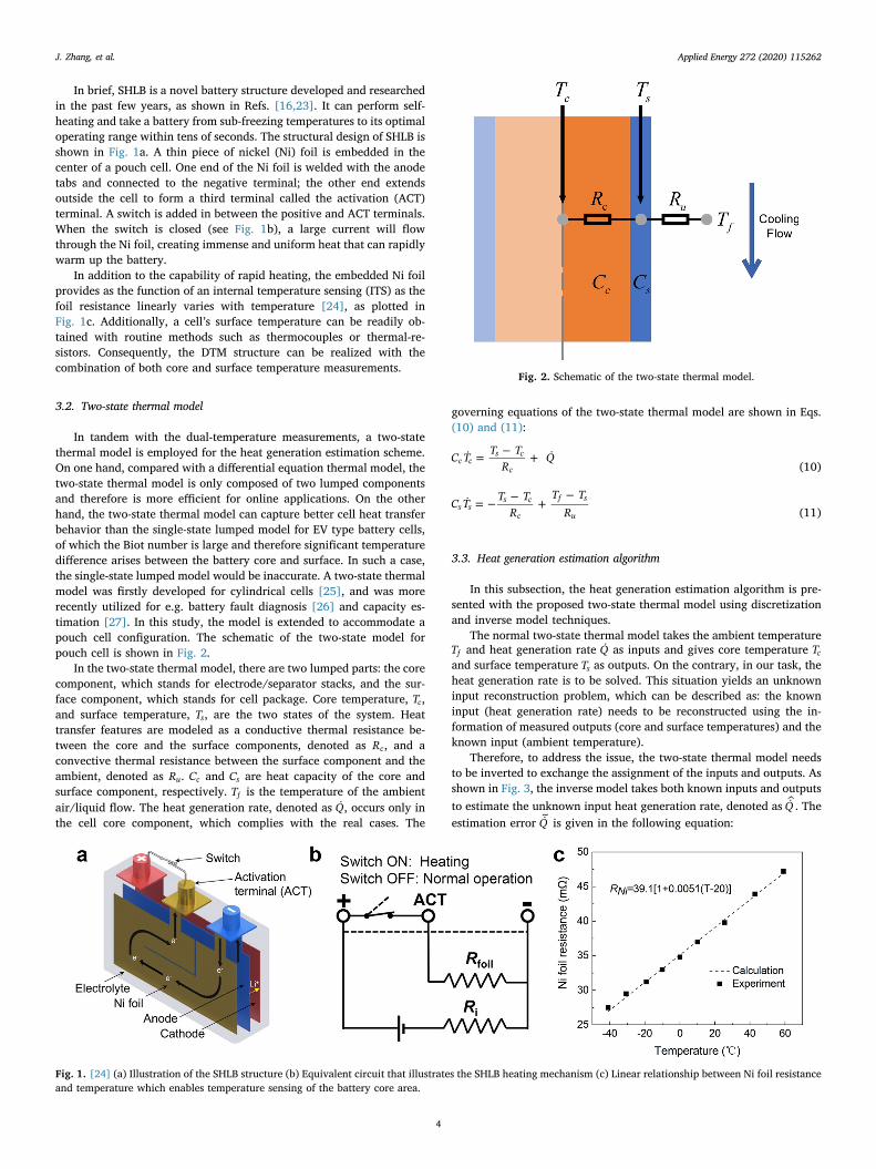
In brief, SHLB is a novel battery structure developed and researchedin the past few years, as shown in Refs. [16,23]. It can perform self-heating and take a battery from sub-freezing temperatures to its optimaloperating range within tens of seconds. The structural design of SHLB isshown in Fig. 1a. A thin piece of nickel (Ni) foil is embedded in thecenter of a pouch cell. One end of the Ni foil is welded with the anodetabs and connected to the negative terminal; the other end extendsoutside the cell to form a third terminal called the activation (ACT)terminal. A switch is added in between the positive and ACT terminals.When the switch is closed (see Fig. 1b), a large current will flowthrough the Ni foil, creating immense and uniform heat that can rapidlywarm up the battery.
In addition to the capability of rapid heating, the embedded Ni foilprovides as the function of an internal temperature sensing (ITS) as thefoil resistance linearly varies with temperature [24], as plotted inFig. 1c. Additionally, a cell’s surface temperature can be readily ob-tained with routine methods such as thermocouples or thermal-re-sistors. Consequently, the DTM structure can be realized with thecombination of both core and surface temperature measurements.
3.2. Two-state thermal model
In tandem with the dual-temperature measurements, a two-statethermal model is employed for the heat generation estimation scheme.On one hand, compared with a differential equation thermal model, thetwo-state thermal model is only composed of two lumped componentsand therefore is more efficient for online applications. On the otherhand, the two-state thermal model can capture better cell heat transferbehavior than the single-state lumped model for EV type battery cells,of which the Biot number is large and therefore significant temperaturedifference arises between the battery core and surface. In such a case,the single-state lumped model would be inaccurate. A two-state thermalmodel was firstly developed for cylindrical cells [25], and was morerecently utilized for e.g. battery fault diagnosis [26] and capacity es-timation [27]. In this study, the model is extended to accommodate apouch cell configuration. The schematic of the two-state model forpouch cell is shown in Fig. 2.
In the two-state thermal model, there are two lumped parts: the corecomponent, which stands for electrode/separator stacks, and the sur-face component, which stands for cell package. Core temperature, Tc,and surface temperature, Ts, are the two states of the system. Heattransfer features are modeled as a conductive thermal resistance be-tween the core and the surface components, denoted as Rc, and aconvective thermal resistance between the surface component and theambient, denoted as Ru. Cc and Cs are heat capacity of the core andsurface component, respectively. Tf is the temperature of the ambientair/liquid flow. The heat generation rate, denoted as Q , occurs only inthe cell core component, which complies with the real cases. The
governing equations of the two-state thermal model are shown in Eqs.(10) and (11):
= − +C T T TR
Q c cs c
c (10)
= − − +−
C T T TR
T TR
s ss c
c
f s
u (11)
3.3. Heat generation estimation algorithm
In this subsection, the heat generation estimation algorithm is pre-sented with the proposed two-state thermal model using discretizationand inverse model techniques.
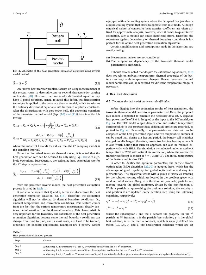
The normal two-state thermal model takes the ambient temperatureTf and heat generation rate Q as inputs and gives core temperature Tcand surface temperature Ts as outputs. On the contrary, in our task, theheat generation rate is to be solved. This situation yields an unknowninput reconstruction problem, which can be described as: the knowninput (heat generation rate) needs to be reconstructed using the in-formation of measured outputs (core and surface temperatures) and theknown input (ambient temperature).
Therefore, to address the issue, the two-state thermal model needsto be inverted to exchange the assignment of the inputs and outputs. Asshown in Fig. 3, the inverse model takes both known inputs and outputsto estimate the unknown input heat generation rate, denoted as Q . Theestimation error Q
~is given in the following equation:
Fig. 1. [24] (a) Illustration of the SHLB structure (b) Equivalent circuit that illustrates the SHLB heating mechanism (c) Linear relationship between Ni foil resistanceand temperature which enables temperature sensing of the battery core area.
Fig. 2. Schematic of the two-state thermal model.
J. Zhang, et al. Applied Energy 272 (2020) 115262
4
= −Q Q Q~ (12)
An inverse heat transfer problem focuses on using measurements ofthe system states to determine one or several characteristics causingsuch states [28]. However, the inverse of a differential equation mayhave ill-posed solutions. Hence, to avoid this defect, the discretizationtechnique is applied to the two-state thermal model, which transformsthe ordinary differential equations into linearized algebraic equations.After the discretization with zero-order hold, the governing equationsof the two-state thermal model (Eqs. (10) and (11)) turn into the fol-lowing:
⎜ ⎟= + − ⎛⎝
− ⎞⎠
− ++T T Q R tC R
T T Q R exp Δ ( )c k s k k cc c
s k c k k c, 1 , , ,(13)
=+ − −
+ − + −++( )
TR T R T
R R C R R R T R T R T R T
exp
( )[ ( )]s kc f k u c k
tR R
c u s c u c f k c s k u c k u s k, 1
, ,Δ
, , , ,
c u
(14)
where the subscript k stands for values from the kth sampling and tΔ isthe sampling interval.
From the discretized two-state thermal model, it is noted that theheat generation rate can be deduced by only using Eq. (13) with alge-braic operations. Subsequently, the estimated heat generation rate forthe kth step is expressed as:
=− − − ⎡
⎣− − ⎤
⎦⎡⎣
− − ⎤⎦
+ ( ) ( )( )
QT T T
R
exp 1 exp
1 expk
c k c kt
C R s kt
C R
ct
C R
, 1 ,Δ
,Δ
Δ
c c c c
c c (15)
With the presented inverse model, the heat generation estimationprocess is listed in Table 1.
It can also be noticed that Tf and Ru terms are absent from the heatgeneration estimation equation, Eq. (15). Therefore, the estimationalgorithm will not be affected by thermal boundary conditions, i.e.,ambient temperature and convection conditions. This feature comesfrom the fact that the surface temperature measurement already con-tains the information from the thermal boundary. This characteristic isvery important for the feasibility and robustness of the heat generationestimation algorithm, because some thermal boundary conditions canchange from time to time, and in most cases, are hard to be tracked,especially for onboard applications. Examples are a battery system
equipped with a fan cooling system where the fan speed is adjustable ora liquid cooling system that starts to operate from idle mode. Althoughempirical values of convective heat transfer coefficient are often uti-lized for approximate analysis, however, when it comes to quantitativeestimation, such a method can cause significant errors. Therefore, therobustness against dependency on thermal boundary conditions is im-portant for the online heat generation estimation algorithm.
Certain simplifications and assumptions made in the algorithm areworthy noting:
(a) Measurement noises are not considered;(b) The temperature dependency of the two-state thermal model
parameters is neglected.
It should also be noted that despite the estimation equation Eq. (15)does not rely on ambient temperatures; thermal properties of the bat-tery can vary with temperature changes. Hence, two-state thermalmodel parameters can be identified for different temperature ranges ifnecessary.
4. Results & discussion
4.1. Two-state thermal model parameter identification
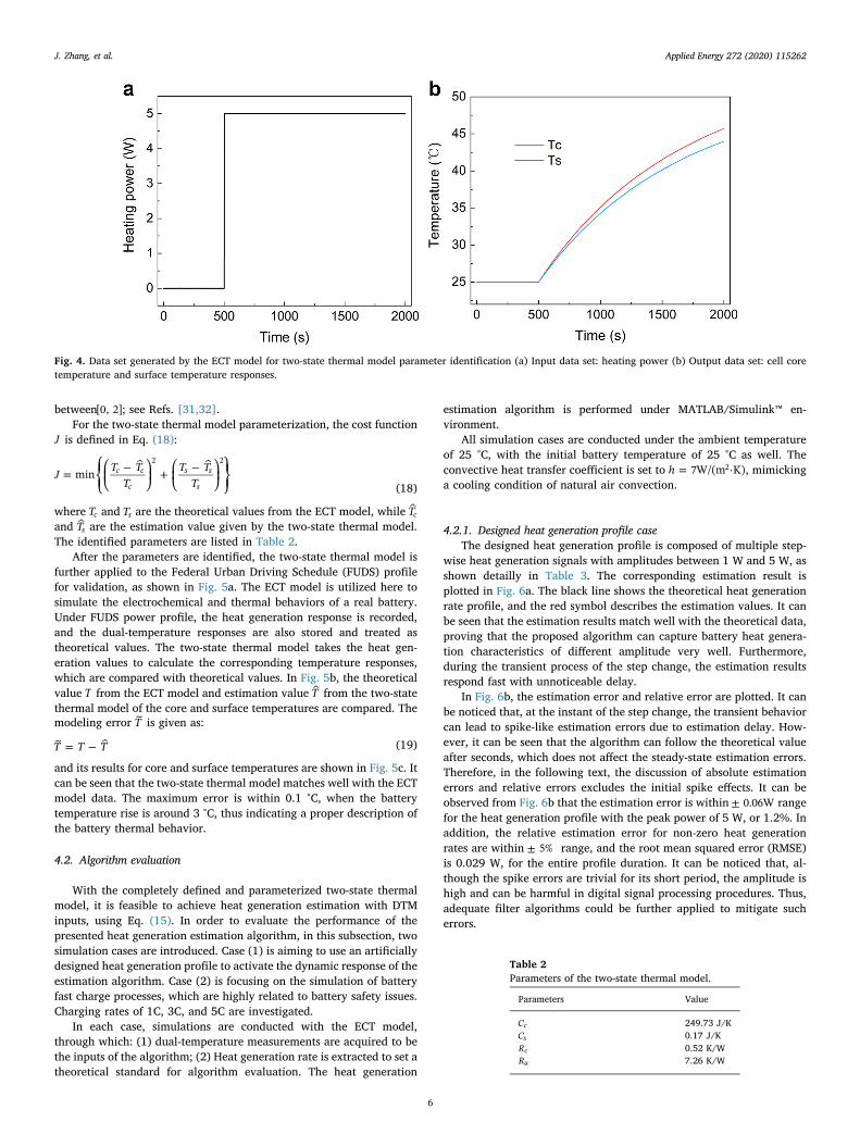
Before digging into the estimation results of heat generation, thetwo-state thermal model needs to be parameterized. Here, the proposedECT model is exploited to generate the necessary data set. A stepwiseheat power profile of 5 W is designed as the input to the ECT model, seeFig. 4a. The ECT model output data of core and surface temperaturecorresponding to this stepwise heat generation profile are recorded, asplotted in Fig. 4b. Eventually, the parametrization data set can becomposed of the heat generation input and two temperature outputs. Itcan be noted that, during this heating period, the battery cell is neithercharged nor discharged; therefore, no electrochemical heating occurs. Itis also worth noting that such an approach can also be realized ex-perimentally with SHLB. The simulation is conducted under an ambienttemperature of 25℃ with natural air convection, where the convectivetransfer coefficient is chosen as =h 7W/(m ·K)2 . The initial temperatureof the battery cell is also 25℃.
In order to identify the optimum parameters, the particle swarmoptimization (PSO) algorithm [29,30] is adopted here, which has theadvantage of good capability for global optimization and easy im-plementation. The algorithm works with a group of particles standingfor the solution vectors, which are located in the problem space withrandom initial values. Along with the iteration proceeds, particles aremoving towards the global minimum, driven by the cost function J .While a particle is approaching the optimum solution, the velocity vand position x are updated every iteration step using the followingequations, respectively:
= + − + −+v wv c p x c g x( ) ( )ik
ik
ik
ik
ik
ik1
1 2 (16)
= ++ +x x vik
ik
ik1 1 (17)
where the subscription i and the k denotes the property for the ith
particle at kth iteration, p is the particle best solution, g is the globalbest solution, w is the inertia constant, which is usually defined be-tween [0.7, 0.8], c1 and c2 are acceleration constants which are set
Fig. 3. Schematic of the heat generation estimation algorithm using inversemodel method.
Table 1Heat generation estimation process.
Steps Content
Step 1 At time step k , measurement of Tc and Ts are updated and held for the +k 1th estimation.Step 2 At time step +k 1, measurement value of Tc and Ts are updated and held for the +k 1th and +k 2th estimation.Step 3 At time step +k 1, kth and +k 1th measurements of Tc and Ts are taken by the heat generation estimation algorithm and update the estimation of Qk .
J. Zhang, et al. Applied Energy 272 (2020) 115262
5
between[0, 2]; see Refs. [31,32].For the two-state thermal model parameterization, the cost function
J is defined in Eq. (18):
⎜ ⎟ ⎜ ⎟= ⎧
⎨⎩
⎛⎝
− ⎞⎠
+ ⎛⎝
− ⎞⎠
⎫⎬⎭
J T TT
T TT
min c c
c
s s
s
2 2
(18)
where Tc and Ts are the theoretical values from the ECT model, while Tcand Ts are the estimation value given by the two-state thermal model.The identified parameters are listed in Table 2.
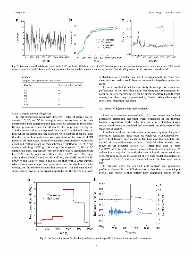
After the parameters are identified, the two-state thermal model isfurther applied to the Federal Urban Driving Schedule (FUDS) profilefor validation, as shown in Fig. 5a. The ECT model is utilized here tosimulate the electrochemical and thermal behaviors of a real battery.Under FUDS power profile, the heat generation response is recorded,and the dual-temperature responses are also stored and treated astheoretical values. The two-state thermal model takes the heat gen-eration values to calculate the corresponding temperature responses,which are compared with theoretical values. In Fig. 5b, the theoreticalvalue T from the ECT model and estimation value T from the two-statethermal model of the core and surface temperatures are compared. Themodeling error T~ is given as:
= −T T T~ (19)
and its results for core and surface temperatures are shown in Fig. 5c. Itcan be seen that the two-state thermal model matches well with the ECTmodel data. The maximum error is within 0.1 °C, when the batterytemperature rise is around 3 °C, thus indicating a proper description ofthe battery thermal behavior.
4.2. Algorithm evaluation
With the completely defined and parameterized two-state thermalmodel, it is feasible to achieve heat generation estimation with DTMinputs, using Eq. (15). In order to evaluate the performance of thepresented heat generation estimation algorithm, in this subsection, twosimulation cases are introduced. Case (1) is aiming to use an artificiallydesigned heat generation profile to activate the dynamic response of theestimation algorithm. Case (2) is focusing on the simulation of batteryfast charge processes, which are highly related to battery safety issues.Charging rates of 1C, 3C, and 5C are investigated.
In each case, simulations are conducted with the ECT model,through which: (1) dual-temperature measurements are acquired to bethe inputs of the algorithm; (2) Heat generation rate is extracted to set atheoretical standard for algorithm evaluation. The heat generation
estimation algorithm is performed under MATLAB/Simulink™ en-vironment.
All simulation cases are conducted under the ambient temperatureof 25 °C, with the initial battery temperature of 25 °C as well. Theconvective heat transfer coefficient is set to =h 7W/(m ·K)2 , mimickinga cooling condition of natural air convection.
4.2.1. Designed heat generation profile caseThe designed heat generation profile is composed of multiple step-
wise heat generation signals with amplitudes between 1 W and 5 W, asshown detailly in Table 3. The corresponding estimation result isplotted in Fig. 6a. The black line shows the theoretical heat generationrate profile, and the red symbol describes the estimation values. It canbe seen that the estimation results match well with the theoretical data,proving that the proposed algorithm can capture battery heat genera-tion characteristics of different amplitude very well. Furthermore,during the transient process of the step change, the estimation resultsrespond fast with unnoticeable delay.
In Fig. 6b, the estimation error and relative error are plotted. It canbe noticed that, at the instant of the step change, the transient behaviorcan lead to spike-like estimation errors due to estimation delay. How-ever, it can be seen that the algorithm can follow the theoretical valueafter seconds, which does not affect the steady-state estimation errors.Therefore, in the following text, the discussion of absolute estimationerrors and relative errors excludes the initial spike effects. It can beobserved from Fig. 6b that the estimation error is within ± 0.06W rangefor the heat generation profile with the peak power of 5 W, or 1.2%. Inaddition, the relative estimation error for non-zero heat generationrates are within ± 5% range, and the root mean squared error (RMSE)is 0.029 W, for the entire profile duration. It can be noticed that, al-though the spike errors are trivial for its short period, the amplitude ishigh and can be harmful in digital signal processing procedures. Thus,adequate filter algorithms could be further applied to mitigate sucherrors.
Fig. 4. Data set generated by the ECT model for two-state thermal model parameter identification (a) Input data set: heating power (b) Output data set: cell coretemperature and surface temperature responses.
Table 2Parameters of the two-state thermal model.
Parameters Value
Cc 249.73 J/KCs 0.17 J/KRc 0.52 K/WRu 7.26 K/W
J. Zhang, et al. Applied Energy 272 (2020) 115262
6
4.2.2. Constant current charge caseIn this subsection, cases with different C-rates of charge are ex-
amined. 1C, 3C, and 5C fast charging scenarios are selected for theirconsiderable heat generation and greater safety concern. In these cases,the heat generation results for different C-rates are presented in Fig. 7a.The theoretical values are exported from the ECT model and shown inlines whilst the estimation values are shown in symbols. It can be foundthat the curves of estimation can keep good track of the theoretical ECTmodel in all three cases. In order to evaluate quantitatively, estimationerrors and relative errors for each subcase are plotted in Fig. 7b–d andobserved within ± 0.05W, ± 0.1W and ± 0.2W range for 1C, 3C, and 5Ccharge rate cases, respectively. Moreover, the relative estimation errorsfor 1C, 3C, and 5C cases are within ± 10% , ± 2.5% and ± 2% rangeafter a short initial fluctuation. In addition, the RMSE are 0.010 W,0.029 W and 0.029 W each. It can be seen that, with a larger current,which also means a larger heat generation rate, the absolute error in-creases, but the relative error further decreases. This indicates the ab-solute error grows with the signal amplitude, but the degree of growth
of absolute error is smaller than that of the signal amplitude. Therefore,the estimation method could be more accurate for large heat generationcases.
It can be concluded that the case study shows a precise estimationperformance of the algorithm under fast charging circumstances. Bydoing so, battery charging safety can be further monitored, and thermalrunaway accidents may be prevented by further taking advantage ofsuch a fault detection technique.
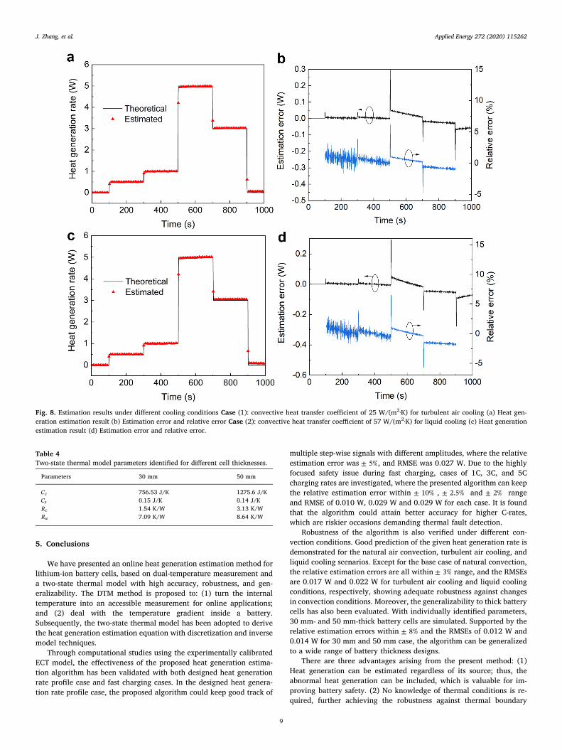
4.3. Effects of different convection conditions
From the expression presented in Eq. (15), one can see that the heatgeneration estimation algorithm works regardless of the thermalboundary conditions. In this subsection, the effects of different con-vection conditions are simulated and discussed; the robustness of thealgorithm is verified.
In order to evaluate the estimation performance against changes inconvection conditions, three cases are employed with different con-vective heat transfer coefficients, h. The base case that simulates thenatural air convection case with =h 7W/(m ·K)2 has already beenshown in the previous Section 4.2.1. After that, case (1) uses
=h 20W/(m ·K)2 to realize an air turbulent flow situation and case (2)utilizes =h 57W/(m ·K)2 to study the case of liquid cooling condition[33]. All three cases use the same set of two-state model parameters, asdisplayed in Table 2, which are identified under the base case condi-tion.
In this case study, the designed multi-stepwise heat generationprofile is adopted for the ECT simulation rather than a current inputprofile. The reason is that battery heat generation caused by its
Fig. 5. Two-state model validation results with FUDS profile (a) FUDS current profile (b) Core temperature and surface temperature validation results (ECT modelvalues are marked with “theoretical”, and two-state thermal model values are marked as “model”) (c) Modeling errors of the two-state thermal model.
Table 3Designed heat generation rate profile.
Time (s) Heat generation rate (W)
100 0300 0.5500 1700 5900 31000 0
Fig. 6. (a) Estimation result for the designed heat generation profile (b) Estimation error and relative error.
J. Zhang, et al. Applied Energy 272 (2020) 115262
7

electrochemical reaction is highly coupled with temperature, which canbe further influenced by different thermal boundary conditions.Therefore, such an effect can lead to incomparability between cases.Using a defined heat generation profile could eliminate this problemand decouple the heat generation rate from cell temperature, thusachieving valid comparisons.
As can be seen from Fig. 8a and c, with a wide range of convectionconditions, the estimation results for case (1) and (2) still show ex-cellent match of the given heat generation rate profile and performuniformly with the base case, which proves the independency on heatconvection condition of the algorithm. In addition, as shown in Fig. 8band d, estimation errors are within ± 0.1W range, while the amplituderange of the theoretical value is from 0 W to 5 W, except for the spike-like errors. The relative estimation error for non-zero heat generationrate values in case (1) and (2) are both within± 3%, and the RMSEs are0.017 W and 0.022 W each. The error ranges are quite small and also atthe same level as the base case, where the absolute error, relative error,and RMSE are within ± 0.06W, ± 5% range, and 0.027 W, respectively.
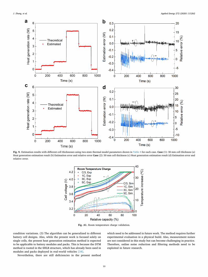
4.4. Effects of cell thickness
To date, EV type batteries are characterized by high energy densityand high capacity. High-capacity active materials meet such needs onone hand. On the other hand, thick electrodes are used and cell thick-ness and volume increase. For large scale batteries, the internal tem-perature distribution can be non-uniform, hence whether the two-statemodel is applicable to those EV batteries of different thickness is an
open question.As introduced earlier in Section 3.2, the two-state thermal model is
an improved lumped model. Therefore, in this subsection, simulationevaluation is conducted to perceive if cells with different thicknessescan be well modeled. Other than the base case cell thickness of 10 mm,the study is extended to cover cell thicknesses of 30 mm and 50 mm. Itis worth noting that, with the increase of cell thickness, a cell also gainsmore thermal mass. Therefore, parameters for each cell thickness arere-identified using the same method introduced in Section 4.1. Theidentified parameters are presented in Table 4. The validation methodis identical to that used in Section 4.3. Fig. 9a and c show the estimationresults for both 30 mm- and 50 mm-thick cells by using respectivemodels. It can be seen that, although subject to the assumption of onlytwo thermal states, the model still shows excellent estimation perfor-mance for the above-studied cell thicknesses, which can cover a largeportion of EV type battery cells. The estimation errors for both cases, asshown in Fig. 9b and d, are within ± 0.05W and the relative estimationerrors for non-zero heat generation rate are within ± 6% and ± 8% for30 mm- and 50 mm-thickness case, respectively, and the RMSEs are0.012 W and 0.014 W each. Although it can be noticed that the esti-mation fluctuations for thicker cells become more apparent, probablydue to larger heat capacity. The algorithm can still follow with rea-sonable precision, with low overall RMSE. Under this circumstance,measurement noise could become more significant in practice andtherefore need to be controlled by filtering techniques.
Fig. 7. (a) Estimation results for constant current charge with 1C, 3C and 5C rates (b) Estimation error and relative error for 1C charge (c) Estimation error andrelative error for 3C charge (d) Estimation error and relative error for 5C charge.
J. Zhang, et al. Applied Energy 272 (2020) 115262
8
5. Conclusions
We have presented an online heat generation estimation method forlithium-ion battery cells, based on dual-temperature measurement anda two-state thermal model with high accuracy, robustness, and gen-eralizability. The DTM method is proposed to: (1) turn the internaltemperature into an accessible measurement for online applications;and (2) deal with the temperature gradient inside a battery.Subsequently, the two-state thermal model has been adopted to derivethe heat generation estimation equation with discretization and inversemodel techniques.
Through computational studies using the experimentally calibratedECT model, the effectiveness of the proposed heat generation estima-tion algorithm has been validated with both designed heat generationrate profile case and fast charging cases. In the designed heat genera-tion rate profile case, the proposed algorithm could keep good track of
multiple step-wise signals with different amplitudes, where the relativeestimation error was ± 5%, and RMSE was 0.027 W. Due to the highlyfocused safety issue during fast charging, cases of 1C, 3C, and 5Ccharging rates are investigated, where the presented algorithm can keepthe relative estimation error within ± 10% , ± 2.5% and ± 2% rangeand RMSE of 0.010 W, 0.029 W and 0.029 W for each case. It is foundthat the algorithm could attain better accuracy for higher C-rates,which are riskier occasions demanding thermal fault detection.
Robustness of the algorithm is also verified under different con-vection conditions. Good prediction of the given heat generation rate isdemonstrated for the natural air convection, turbulent air cooling, andliquid cooling scenarios. Except for the base case of natural convection,the relative estimation errors are all within ± 3% range, and the RMSEsare 0.017 W and 0.022 W for turbulent air cooling and liquid coolingconditions, respectively, showing adequate robustness against changesin convection conditions. Moreover, the generalizability to thick batterycells has also been evaluated. With individually identified parameters,30 mm- and 50 mm-thick battery cells are simulated. Supported by therelative estimation errors within ± 8% and the RMSEs of 0.012 W and0.014 W for 30 mm and 50 mm case, the algorithm can be generalizedto a wide range of battery thickness designs.
There are three advantages arising from the present method: (1)Heat generation can be estimated regardless of its source; thus, theabnormal heat generation can be included, which is valuable for im-proving battery safety. (2) No knowledge of thermal conditions is re-quired, further achieving the robustness against thermal boundary
Fig. 8. Estimation results under different cooling conditions Case (1): convective heat transfer coefficient of 25 W/(m2·K) for turbulent air cooling (a) Heat gen-eration estimation result (b) Estimation error and relative error Case (2): convective heat transfer coefficient of 57 W/(m2·K) for liquid cooling (c) Heat generationestimation result (d) Estimation error and relative error.
Table 4Two-state thermal model parameters identified for different cell thicknesses.
Parameters 30 mm 50 mm
Cc 756.53 J/K 1275.6 J/KCs 0.15 J/K 0.14 J/KRc 1.54 K/W 3.13 K/WRu 7.09 K/W 8.64 K/W
J. Zhang, et al. Applied Energy 272 (2020) 115262
9
condition variations. (3) The algorithm can be generalized to differentbattery cell designs. Also, while the present work is focused solely onsingle cells, the present heat generation estimation method is expectedto be applicable to battery modules and packs. This is because the DTMmethod is rooted in the SHLB structure, which has already been used inmodules and packs deployed in real-world vehicles [34].
Nevertheless, there are still deficiencies in the present method
which need to be addressed in future work. The method requires furtherexperimental evaluation in a physical build. Also, measurement noisesare not considered in this study but can become challenging in practice.Therefore, online noise reduction and filtering methods need to beexploited in future research.
Fig. 9. Estimation results with different cell thicknesses using two-state thermal model parameters shown in Table 4 for each case. Case (1): 30 mm cell thickness (a)Heat generation estimation result (b) Estimation error and relative error Case (2): 50 mm cell thickness (c) Heat generation estimation result (d) Estimation error andrelative error.
Fig. A1. Room temperature charge validation.
J. Zhang, et al. Applied Energy 272 (2020) 115262
10
CRediT authorship contribution statement
Jianan Zhang: Conceptualization, Methodology, Software,Visualization, Investigation, Writing - original draft, Writing - review &editing. Xiao-Guang Yang: Validation, Writing - review & editing.Fengchun Sun: Supervision. Zhenpo Wang: Supervision. Chao-YangWang: Supervision, Writing - review & editing.
Declaration of Competing Interest
The authors declare that they have no known competing financial
interests or personal relationships that could have appeared to influ-ence the work reported in this paper.
Acknowledgment
JZ, FS, and ZW acknowledge partial support of this work by theState Key Program of the National Natural Science Foundation of Chinaunder Grant U1564206, and JZ is further supported in part by the ChinaScholarship Council under Grant 201706030101. We are also gratefulto Gamma Technologies for offering GT-AutoLion™ software.
Appendix A. Electrochemical-thermal model validation against experimental results
See Figs. A1–A3.
References
[1] Zhang J, Zhang L, Sun F, Wang Z. An overview on thermal safety issues of lithium-ion batteries for electric vehicle application. IEEE Access 2018;6:23848–63.
[2] Zhang J, Huang J, Li Z, Wu B, Nie Z, Sun Y, et al. Comparison and validation ofmethods for estimating heat generation rate of large-format lithium-ion batteries. JTherm Anal Calorim 2014;117:447–61.
[3] Manikandan B, Yap C, Balaya P. Towards understanding heat generation char-acteristics of Li-ion batteries by calorimetry, impedance, and potentiometry studies.J Electrochem Soc 2017;164:A2794–800.
[4] Farag M, Sweity H, Fleckenstein M, Habibi S. Combined electrochemical, heatgeneration, and thermal model for large prismatic lithium-ion batteries in real-timeapplications. J Power Sources 2017;360:618–33.
[5] Chen K, Unsworth G, Li X. Measurements of heat generation in prismatic Li-ionbatteries. J Power Sources 2014;261:28–37.
[6] Drake SJ, Martin M, Wetz DA, Ostanek JK, Miller SP, Heinzel JM, et al. Heat gen-eration rate measurement in a Li-ion cell at large C-rates through temperature andheat flux measurements. J Power Sources 2015;285:266–73.
[7] Bernardi D, Pawlikowski E, Newman J. A general energy balance for battery sys-tems. J Electrochem Soc 1985;132:5–12.
[8] Rao L, Newman J. Heat-generation rate and general energy balance for insertionbattery systems. J Electrochem Soc 1997;144:2697–704.
[9] Greco A, Cao D, Jiang X, Yang H. A theoretical and computational study of lithium-ion battery thermal management for electric vehicles using heat pipes. J PowerSources 2014;257:344–55.
[10] Rao Z, Wang S, Zhang G. Simulation and experiment of thermal energy manage-ment with phase change material for ageing LiFePO4 power battery. EnergyConvers Manage 2011;52:3408–14.
[11] Xie Y, Shi S, Tang J, Wu H, Yu J. Experimental and analytical study on heat gen-eration characteristics of a lithium-ion power battery. Int J Heat Mass Transf2018;122:884–94.
Fig. A2. Room temperature discharge validation.
Fig. A3. 1C discharge validation under different temperatures.
J. Zhang, et al. Applied Energy 272 (2020) 115262
11

[12] Zhang G, Cao L, Ge S, Wang C-Y, Shaffer CE, Rahn CD. Reaction temperaturesensing (RTS)-based control for Li-ion battery safety. Sci Rep 2015;5:18237.
[13] Srinivasan R, Carkhuff BG, Butler MH, Baisden AC. Instantaneous measurement ofthe internal temperature in lithium-ion rechargeable cells. Electrochim Acta2011;56:6198–204.
[14] Kim Y, Mohan S, Siegel JB, Stefanopoulou AG, Ding Y. The estimation of tem-perature distribution in cylindrical battery cells under unknown cooling conditions.IEEE Trans Control Syst Technol 2014;22:2277–86.
[15] Li Z, Zhang J, Wu B, Huang J, Nie Z, Sun Y, et al. Examining temporal and spatialvariations of internal temperature in large-format laminated battery with embeddedthermocouples. J Power Sources 2013;241:536–53.
[16] Wang C-Y, Zhang G, Ge S, Xu T, Ji Y, Yang X-G, et al. Lithium-ion battery structurethat self-heats at low temperatures. Nature 2016;529:515.
[17] Gamma Technologies. GT-AutoLion; 2019. Available from: https://www.gtisoft.com/gt-autolion/.
[18] Gu WB, Wang CY. Thermal-electrochemical modeling of battery systems. JElectrochem Soc 2000;147:2910–22.
[19] Ji Y, Zhang Y, Wang C-Y. Li-ion cell operation at low temperatures. J ElectrochemSoc 2013;160:A636–49.
[20] Yang X-G, Zhang G, Wang C-Y. Computational design and refinement of self-heatinglithium ion batteries. J Power Sources 2016;328:203–11.
[21] Al Hallaj S, Maleki H, Hong JS, Selman JR. Thermal modeling and design con-siderations of lithium-ion batteries. J Power Sources 1999;83:1–8.
[22] Zhang J, Wu B, Li Z, Huang J. Simultaneous estimation of thermal parameters forlarge-format laminated lithium-ion batteries. J Power Sources 2014;259:106–16.
[23] Yang X-G, Zhang G, Ge S, Wang C-Y. Fast charging of lithium-ion batteries at alltemperatures. Proc Natl Acad Sci 2018;115:7266–71.
[24] Zhang G, Ge S, Xu T, Yang X-G, Tian H, Wang C-Y. Rapid self-heating and internaltemperature sensing of lithium-ion batteries at low temperatures. Electrochim Acta
2016;218:149–55.[25] Lin X, Perez HE, Siegel JB, Stefanopoulou AG, Li Y, Anderson RD, et al. Online
parameterization of lumped thermal dynamics in cylindrical lithium ion batteriesfor core temperature estimation and health monitoring. IEEE Trans Control SystTechnol 2013;21:1745–55.
[26] Dey S, Biron ZA, Tatipamula S, Das N, Mohon S, Ayalew B, et al. Model-based real-time thermal fault diagnosis of Lithium-ion batteries. Control Eng Pract2016;56:37–48.
[27] Zhang D, Dey S, Perez HE, Moura SJ. Real-time capacity estimation of lithium-ionbatteries utilizing thermal dynamics. IEEE Trans Control Syst Technol2020;28:992–1000.
[28] Alifanov OM. Inverse heat transfer problems. Springer Science & Business Media;2012.
[29] Eberhart, Yuhui S. Particle swarm optimization: developments, applications andresources. In: Proceedings of the 2001 Congress on Evolutionary Computation (IEEECat No01TH8546)2001, vol. 1. p. 81–6.
[30] Venter G, Sobieszczanski-Sobieski J. Particle swarm optimization. AIAA J2003;41:1583–9.
[31] Rahman MA, Anwar S, Izadian A. Electrochemical model parameter identificationof a lithium-ion battery using particle swarm optimization method. J Power Sources2016;307:86–97.
[32] Long B, Xian W, Jiang L, Liu Z. An improved autoregressive model by particleswarm optimization for prognostics of lithium-ion batteries. Microelectron Reliab2013;53:821–31.
[33] Pesaran AA. Battery thermal management in EV and HEVs: issues and solutions.Battery Manage 2001;43:34–49.
[34] Yang X, Ge S, Wu N, Mao Y, Sun F, Wang C. All-climate battery technology forelectric vehicles: inching closer to the mainstream adoption of automated driving.IEEE Electrif Mag 2019;7:12–21.
J. Zhang, et al. Applied Energy 272 (2020) 115262
12