an introduction to pile foundations for structures · an introduction to pile foundations for...
TRANSCRIPT
An Approved Continuing Education Provider
PDHonline Course C609 (2 PDH)
An Introduction to Pile Foundations for Structures
J. Paul Guyer, P.E., R.A., Fellow ASCE, Fellow AEI
2012
PDH Online | PDH Center
5272 Meadow Estates Drive Fairfax, VA 22030-6658
Phone & Fax: 703-988-0088 www.PDHonline.org www.PDHcenter.com
www.PDHcenter.com PDHonline Course C609 www.PDHonline.org
© J. Paul Guyer 2012 Page 2 of 28
An Introduction to Pile Foundations for Structures
J. Paul Guyer, P.E., R.A., Fellow ASCE, Fellow AEI
CONTENTS
1. INTRODUCTION 2. TYPES OF PILE FOUNDATIONS 3. SELECTION OF PILE FOUNDATIONS
This course is adapted from the Unified Facilities Criteria of the United States government, which is in the public domain, is authorized for unlimited distribution, and is not copyrighted.
The Figures, Tables and Symbols in this document are in some cases a little difficult to read, but they are the best available. DO NOT PURCHASE THIS COURSE IF THE FIGURES, TABLES AND SYMBOLS ARE NOT ACCEPTABLE TO YOU.
www.PDHcenter.com PDHonline Course C609 www.PDHonline.org
© J. Paul Guyer 2012 Page 3 of 28
1. INTRODUCTION 1.1 PURPOSE. This course is an introduction to data, principles, and methods for use
in planning, design, and construction of deep foundations. Deep foundations are
braced column elements (piles) transmitting structure loads down to the subgrade supporting medium. 1.2 SCOPE. This course is introductory and presents only general information with
respect to the selection and design of deep foundations. Single and groups of driven
piles and drilled shafts under axial and lateral static loads are treated. This course is
not intended for hydraulic structures.
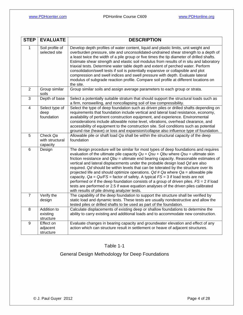
1.3 GENERAL DESIGN METHODOLOGY. A single drilled shaft or a group of driven
piles is typically designed to support a column load. The number of driven piles in a
group is determined by dividing the column load by the design load of a single pile. The
piles should be arranged in the group to provide a spacing of about three to four times
the pile diameter B up to 6B. The diameter of the piles may be increased to reduce the
size of the pile cap if appropriate. Table 1-1 describes a general design methodology.
Other design methodology aspects are the following:
1.3.1 LOAD FACTOR DESIGN. This discussion applies load factors for design (LFD)
of the structural capacity of deep foundations. The sum of the factored loads shall not
exceed the structural resistance and the soil resistance. The LFD, the structural
resistance, and the soil resistance are all related to the load factors as follows:
1.3.1.1 DEFINITION. The LFD may be defined as a concept which recognizes that the
different types i of loads Qi that are applied to a structure have varied probabilities of
occurrence. Examples of types of loads applied to a structure include the live load QLL ,
dead load QDL , wind load QWL , and earthquake load QEL . The probability of
occurrence of each load is accounted for by multiplying each Q by a load factor Fi > 1.0.
The value of F depends on the uncertainty of the load.
www.PDHcenter.com PDHonline Course C609 www.PDHonline.org
© J. Paul Guyer 2012 Page 4 of 28
STEP EVALUATE DESCRIPTION 1 Soil profile of
selected site Develop depth profiles of water content, liquid and plastic limits, unit weight and overburden pressure, site and unconsolidated-undrained shear strength to a depth of a least twice the width of a pile group or five times the tip diameter of drilled shafts. Estimate shear strength and elastic soil modulus from results of in situ and laboratory triaxial tests. Determine water table depth and extent of perched water. Perform consolidation/swell tests if soil is potentially expansive or collapsible and plot compression and swell indices and swell pressure with depth. Evaluate lateral modulus of subgrade reaction profile. Compare soil profile at different locations on the site.
2 Group similar soils
Group similar soils and assign average parameters to each group or strata.
3 Depth of base Select a potentially suitable stratum that should support the structural loads such as a firm, nonswelling, and noncollapsing soil of low compressibility.
4 Select type of deep foundation
Select the type of deep foundation such as driven piles or drilled shafts depending on requirements that foundation include vertical and lateral load resistance, economy, availability of pertinent construction equipment, and experience. Environmental considerations include allowable noise level, vibrations, overhead clearance, and accessibility of equipment to the construction site. Soil conditions such as potential ground rise (heave) or loss and expansion/collapse also influence type of foundation.
5 Check Qa with structural capacity
Allowable pile or shaft load Qa shall be within the structural capacity of the deep foundation
6 Design The design procedure will be similar for most types of deep foundations and requires evaluation of the ultimate pile capacity Qu = Qsu + Qbu where Qsu = ultimate skin friction resistance and Qbu = ultimate end bearing capacity. Reasonable estimates of vertical and lateral displacements under the probable design load Qd are also required. Qd should be within levels that can be tolerated by the structure over its projected life and should optimize operations. Qd # Qa where Qa = allowable pile capacity. Qa = Qu/FS = factor of safety. A typical FS = 3 if load tests are not performed or if the deep foundation consists of a group of driven piles. FS = 2 if load tests are performed or 2.5 if wave equation analyses of the driven piles calibrated with results of pile driving analyzer tests.
7 Verify the design
The capability of the deep foundation to support the structure shall be verified by static load and dynamic tests. These tests are usually nondestructive and allow the tested piles or drilled shafts to be used as part of the foundation.
8 Addition to existing structure
Calculate displacements of existing deep or shallow foundations to determine the ability to carry existing and additional loads and to accommodate new construction.
9 Effect on adjacent structure
Evaluate changes in bearing capacity and groundwater elevation and effect of any action which can structure result in settlement or heave of adjacent structures.
Table 1-1
General Design Methodology for Deep Foundations
www.PDHcenter.com PDHonline Course C609 www.PDHonline.org
© J. Paul Guyer 2012 Page 5 of 28
1.3.1.2 STRUCTURAL RESISTANCE. The sum of the factored loads shall be less
than the design strength:
Npf Qcap = Fi Qi (Eq. 1-1)
where
Npf = performance factor for structural capacity
Qcap = nominal structural capacity, kips
Fi = Load factor of type i
Qi = applied load of type i
1.3.1.3 SOIL RESISTANCE. The sum of the factored loads shall be less than the
ability of the soil to resist the loads. This evaluation may be determined by load factors.
Factors of safety are often empirical values based on past experience and may lead to
a more conservative design than the LFD concept. The FS and the LFD are presented
as:
1.3.1.3.1 GLOBAL FS. The allowable load may be evaluated with global FS:
Qa x (Qu/FS) = Fi x Qi (Eq. 1-2a)
where
Qa = allowable load that can be applied to the soil, kips
Qu = ultimate pile capacity, kips
FS = global factor of safety
The approach taken throughout this discussion is to select a global FS for analysis of
soil resistance rather than partial FS or load factors.
www.PDHcenter.com PDHonline Course C609 www.PDHonline.org
© J. Paul Guyer 2012 Page 6 of 28
1.3.1.3.2 LOAD FACTOR DESIGN. Analysis of soil resistance may also be
determined by the LFD concept using performance factors:
Npfq x Qu = Fi x Qi (Eq. 1-2b)
where Npfq = performance factor appropriate to the ultimate pile capacity. Performance
factors Npfq depend on the method of evaluating Qu and the type of soil resistance,
whether end bearing, skin friction, uplift or a group capacity. Load factors and factors of
safety taken in combination can lead to an uneconomical foundation design.
1.3.2 UNUSUAL SITUATIONS. Consideration should be given to obtaining the
services and advice of specialists and consultants in foundation design where
conditions are unusual or unfamiliar or structures are economically significant. Some
unusual situations for deep foundations, discussed below, include expansive clay,
under-consolidated soil, and coral sands.
1.3.2.1 EXPANSIVE CLAY. The swell of expansive clay can cause an uplift force on
the perimeter area of deep foundations that can force the foundation to move up and
damage the structure connected to the deep foundation.
1.3.2.2 UNDERCONSOLIDATED SOIL. The settlement of under-consolidated soil can
cause negative skin friction on the perimeter area of the deep foundation that can
increase the end-bearing load, which results in an increase in settlement of the
foundation.
1.3.2.3 CORAL SANDS. Piles in coral sands may indicate low penetration resistance
during driving and an apparent low bearing capacity, but the penetration resistance
often increases over time as a result of the dissipation of excess pore pressure. Driving
of piles into cemented, calcareous sands can crush the soil and lower the lateral stress,
which results in a low value for skin friction and bearing capacity.
1.3.3 COMPUTER PROGRAM ASSISTANCE. Design of a deep foundation is
normally accomplished with the assistance of several computer programs.
www.PDHcenter.com PDHonline Course C609 www.PDHonline.org
© J. Paul Guyer 2012 Page 7 of 28
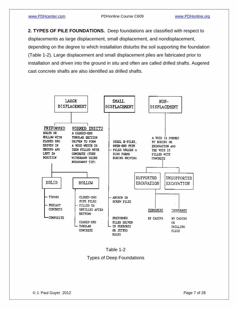
2. TYPES OF PILE FOUNDATIONS. Deep foundations are classified with respect to
displacements as large displacement, small displacement, and nondisplacement,
depending on the degree to which installation disturbs the soil supporting the foundation
(Table 1-2). Large displacement and small displacement piles are fabricated prior to
installation and driven into the ground in situ and often are called drilled shafts. Augered
cast concrete shafts are also identified as drilled shafts.
Table 1-2
Types of Deep Foundations
www.PDHcenter.com PDHonline Course C609 www.PDHonline.org
© J. Paul Guyer 2012 Page 8 of 28
2.1 LARGE DISPLACEMENT PILES. Driven piles are classified by the materials from
which the pile is constructed, i.e., timber, concrete, or filled or unfilled steel pipe.
2.1.1 TIMBER PILES. These are generally used for comparatively light axial and
lateral loads where foundation conditions indicate that piles will not be damaged by
driving or exposed to marine borers. Overdriving is the greatest cause of damage to
timber piles. Pile driving is often decided by a judgment that depends on the pile, soil
condition, and driving equipment. Overdriving typically occurs when the dynamic
stresses on the pile head exceed the ultimate strength of the pile. Timber piles can
broom at the pile tip or head, split, or break when overdriven. Such piles have an
indefinite life when constantly submerged or where cut off below the groundwater level.
Some factors that might affect the performance of timber piles are the following:
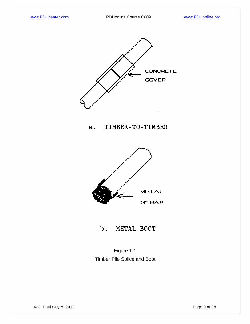
2.1.1.1 Splicing of timber piles is expensive and time consuming and should be
avoided. The full bending resistance of timber pile splices may be obtained by a
concrete cover (Figure 1-1a). Other transition splicers are available to connect timber
with cast concrete or pipe piles.
2.1.1.2 Tips of timber piles can be protected by a metal boot (Figure 1-1b).
2.1.1.3 Timber piles are normally treated with creosote to prevent decay and
environmental attack.
2.1.1.4 American Society for Testing and Materials (ASTM) D 25 provides physical
specifications of round timber piles.
2.1.2 PRECAST CONCRETE PILES. These piles include conventionally reinforced
concrete piles and prestressed concrete piles. Reinforced concrete piles are
constructed with an internal reinforcement cage consisting of several longitudinal bars
and lateral ties, individual hoops, or a spiral.
www.PDHcenter.com PDHonline Course C609 www.PDHonline.org
© J. Paul Guyer 2012 Page 9 of 28
Figure 1-1
Timber Pile Splice and Boot
www.PDHcenter.com PDHonline Course C609 www.PDHonline.org
© J. Paul Guyer 2012 Page 10 of 28
Prestressed concrete piles are constructed using steel rods or wire strands under
tension as reinforcement. Since the concrete is under continuous compression,
transverse cracks tend to remain closed; thus, prestressed piles are usually more
durable than conventionally reinforced piles. Influential factors for precast concrete piles
include splices and steel points.
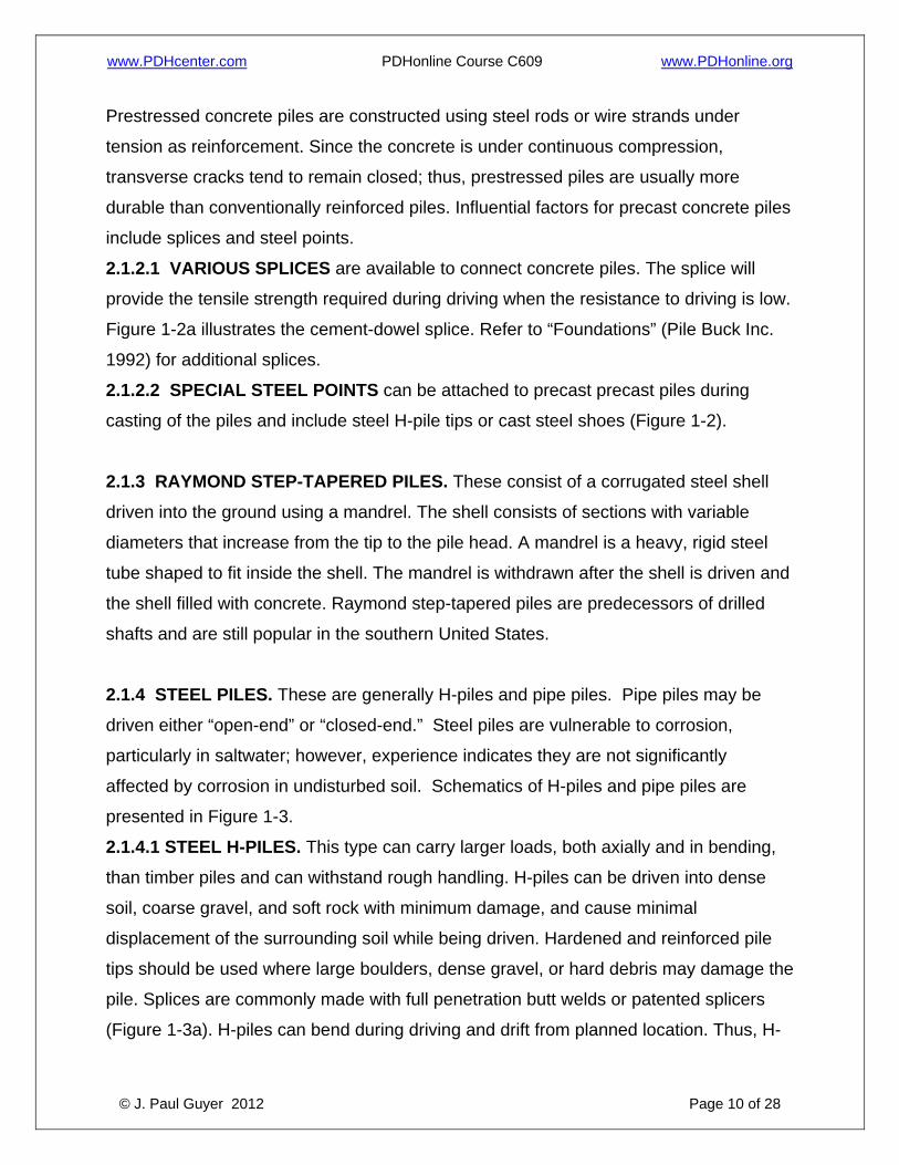
2.1.2.1 VARIOUS SPLICES are available to connect concrete piles. The splice will
provide the tensile strength required during driving when the resistance to driving is low.
Figure 1-2a illustrates the cement-dowel splice. Refer to “Foundations” (Pile Buck Inc.
1992) for additional splices.
2.1.2.2 SPECIAL STEEL POINTS can be attached to precast precast piles during
casting of the piles and include steel H-pile tips or cast steel shoes (Figure 1-2).
2.1.3 RAYMOND STEP-TAPERED PILES. These consist of a corrugated steel shell
driven into the ground using a mandrel. The shell consists of sections with variable
diameters that increase from the tip to the pile head. A mandrel is a heavy, rigid steel
tube shaped to fit inside the shell. The mandrel is withdrawn after the shell is driven and
the shell filled with concrete. Raymond step-tapered piles are predecessors of drilled
shafts and are still popular in the southern United States.
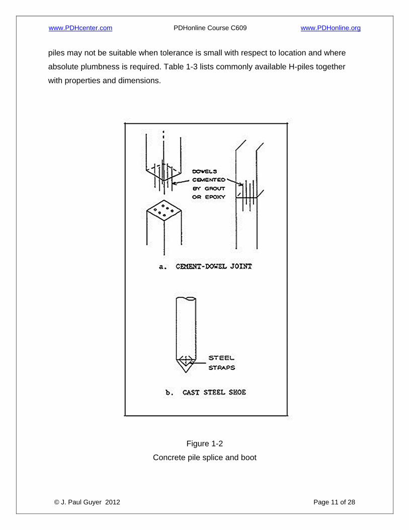
2.1.4 STEEL PILES. These are generally H-piles and pipe piles. Pipe piles may be
driven either “open-end” or “closed-end.” Steel piles are vulnerable to corrosion,
particularly in saltwater; however, experience indicates they are not significantly
affected by corrosion in undisturbed soil. Schematics of H-piles and pipe piles are
presented in Figure 1-3.
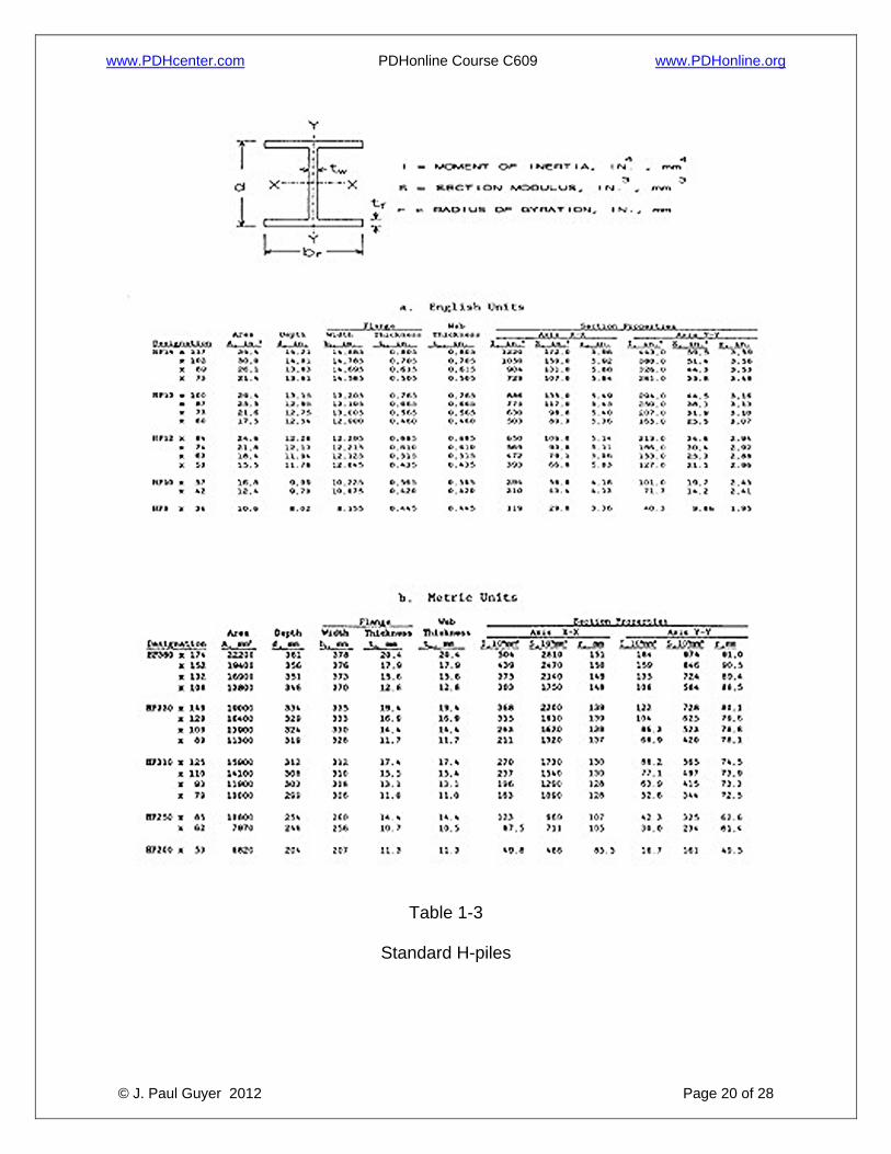
2.1.4.1 STEEL H-PILES. This type can carry larger loads, both axially and in bending,
than timber piles and can withstand rough handling. H-piles can be driven into dense
soil, coarse gravel, and soft rock with minimum damage, and cause minimal
displacement of the surrounding soil while being driven. Hardened and reinforced pile
tips should be used where large boulders, dense gravel, or hard debris may damage the
pile. Splices are commonly made with full penetration butt welds or patented splicers
(Figure 1-3a). H-piles can bend during driving and drift from planned location. Thus, H-
www.PDHcenter.com PDHonline Course C609 www.PDHonline.org
© J. Paul Guyer 2012 Page 11 of 28
piles may not be suitable when tolerance is small with respect to location and where
absolute plumbness is required. Table 1-3 lists commonly available H-piles together
with properties and dimensions.
Figure 1-2
Concrete pile splice and boot
www.PDHcenter.com PDHonline Course C609 www.PDHonline.org
© J. Paul Guyer 2012 Page 12 of 28
Figure 1-3
Steel pile splices
www.PDHcenter.com PDHonline Course C609 www.PDHonline.org
© J. Paul Guyer 2012 Page 13 of 28
2.1.4.2 STEEL PIPE PILES. Steel pipe piles are generally filled with concrete after
driving to increase the structural capacity. If the soil inside the pipe is removed during
driving, open-end piles in cohesionless soil will cause less soil displacement and
compaction, and in cohesive soils will cause less heaving of adjacent ground and
nearby piles. If the soil inside the pipe is not removed during driving, the pipe becomes
plugged and acts as a closed-end displacement pile. Criteria are presently unavailable
for computing the depth at which a driven, open-end pile will plug. In cases where the
foundation contains boulders, soft rock, or other obstructions, the open-end pile permits
inspection after removal of the plug material and ensures that the load will be
transferred directly to the load-bearing stratum. Splices are commonly made by full
penetration butt welds or fillet wells(Figure 1-3b) or patented splicers.
2.1.5 COMPACTION PILES. These are sometimes driven with the objective of
increasing the density of loose, cohesionless soils and reducing settlement. Piles with
a heavy taper are often most effective in deriving their support from friction.
2.2 NONDISPLACEMENT PILES. This pile consists of a drilled shaft with a concrete
cylinder cast into a borehole. Normally, the drilled shaft does not cause major
displacement of the adjacent ground surface. The hole is usually bored with a short
flight or bucket auger. Loss of ground could occur if the diameter of the hole is
decreased because of inward displacement of soft soil or if there is caving of soil from
the hole perimeter. Such unstable boreholes require stabilization by the use of slurry or
slurry and casing. Drilled shafts are not subject to handling or driving stresses and
therefore may be designed only for stresses under the applied service loads.
Nondisplacement may be categorized as follows:
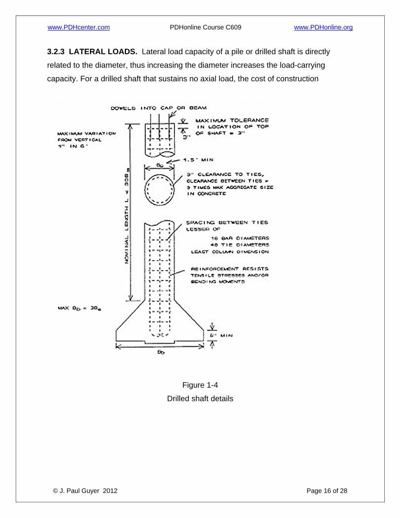
2.2.1 UNCASED SHAFTS. Figure 1-4 illustrates a typical uncased drilled shaft with an
enlarged base. The base is not perfectly flat because the shaft is drilled first, then the
belling tool rotates in the shaft. Uncased shafts may be constructed in firm, stiff soils
where loss of ground is not significant. Examples of uncased shaft are given in the
American Concrete Institute (ACI) Manual of Concrete Practice (1986). Other terms
www.PDHcenter.com PDHonline Course C609 www.PDHonline.org
© J. Paul Guyer 2012 Page 14 of 28
used to describe the drilled shaft are “pier” or “caisson.” Large shafts greater then 36
inches in diameter are often called caissons. The term “pile” is commonly associated
with driven deep foundations of relatively small diameter or cross section.
2.2.2 CASED SHAFTS. A cased shaft is made by inserting a shell or casing into
almost any type of bored hole that requires stabilization before placing concrete.
Boreholes are caused where soil is weak and loose, and loss of ground into the
excavation is significant. The bottom of the casing should be pushed several inches into
an impervious stratum to seal the hole and allow removal of the drilling fluid prior to
completion of the excavation and concrete placement. If an impervious stratum does not
exist to push the casing into, the concrete can be placed by tremie to displace the
drilling fluid.
2.2.3 DRILLING FLUID SHAFTS. Shafts can be installed in wet sands using drilling
fluid, with or without casing. This procedure of installing drilled shafts can be used as an
alternative to the uncased and cased shafts discussed previously.
2.2.4 PRESSURE-GROUTED SHAFTS. A special type of nondisplacement deep
foundation is the uncased auger-placed grout shaft. This shaft is constructed by
advancing a continuous-flight, hollow-stem auger to the required depth and filling the
hole bored by the concrete grout under pressure as the auger is withdrawn. Careful
inspection is required during installation, and shaft continuity should be verified by a
combination of load tests and nondestructive testing.
3. SELECTION OF PILE FOUNDATIONS. Deep foundations provide an efficient
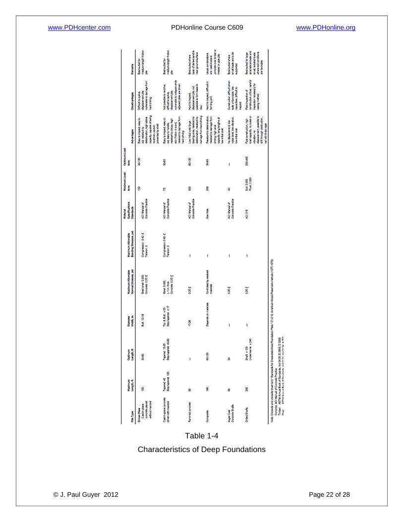
foundation system for soils that do not have a shallow, stable bearing stratum. Selection of a deep foundation requires knowledge of its characteristics and capacity. 3.1 CHARACTERISTICS. Information adequate for reaching preliminary conclusions
about types of driven piles or drilled shafts to be selected for a project is given in Table
1-4. This table lists major types of deep foundations with respect to capacity,
www.PDHcenter.com PDHonline Course C609 www.PDHonline.org
© J. Paul Guyer 2012 Page 15 of 28
application, relative dimensions, and advantages and disadvantages. Refer to
Foundations (Pile Buck Inc. 1992) for general guidelines in the selection of a type of
deep foundation. Relevant codes and standards should be consulted with respect to
allowable stresses. A cost analysis should also be performed that includes installation,
locally available practices, time delays, cost of load testing program, cost of a pile cap,
and other elements that depend on different types of deep foundations.
3.2 CAPACITY. Deep foundations transmit structural loads to deep strata that are
capable of sustaining the applied loads. Accurate predictions of load capacity and
settlement are not always possible. Adequate safety factors are therefore used to avoid
excessive movement that would be detrimental to the structure that is supported and to
avoid excessive stress in the foundation. Driven piles or drilled shafts are often used to
resist vertical inclined, lateral, or uplift forces and overturning moments which cannot
otherwise be resisted by shallow footings. These foundations derive their support from
skin friction along the embedded length and by end bearing at the tip (base). Both
factors contribute to the total ultimate pile capacity, but one or the other is usually
dominant depending on the size, load, and soil characteristics. The capacity of deep
foundation is influenced by several factors:
3.2.1 DESIGN LIMITS. The limiting design criterion is normally influenced by
settlement in soft and moderately stiff soil, and bearing capacity in hard soil or dense
sand, and by pile or shaft structural capacity in rock.
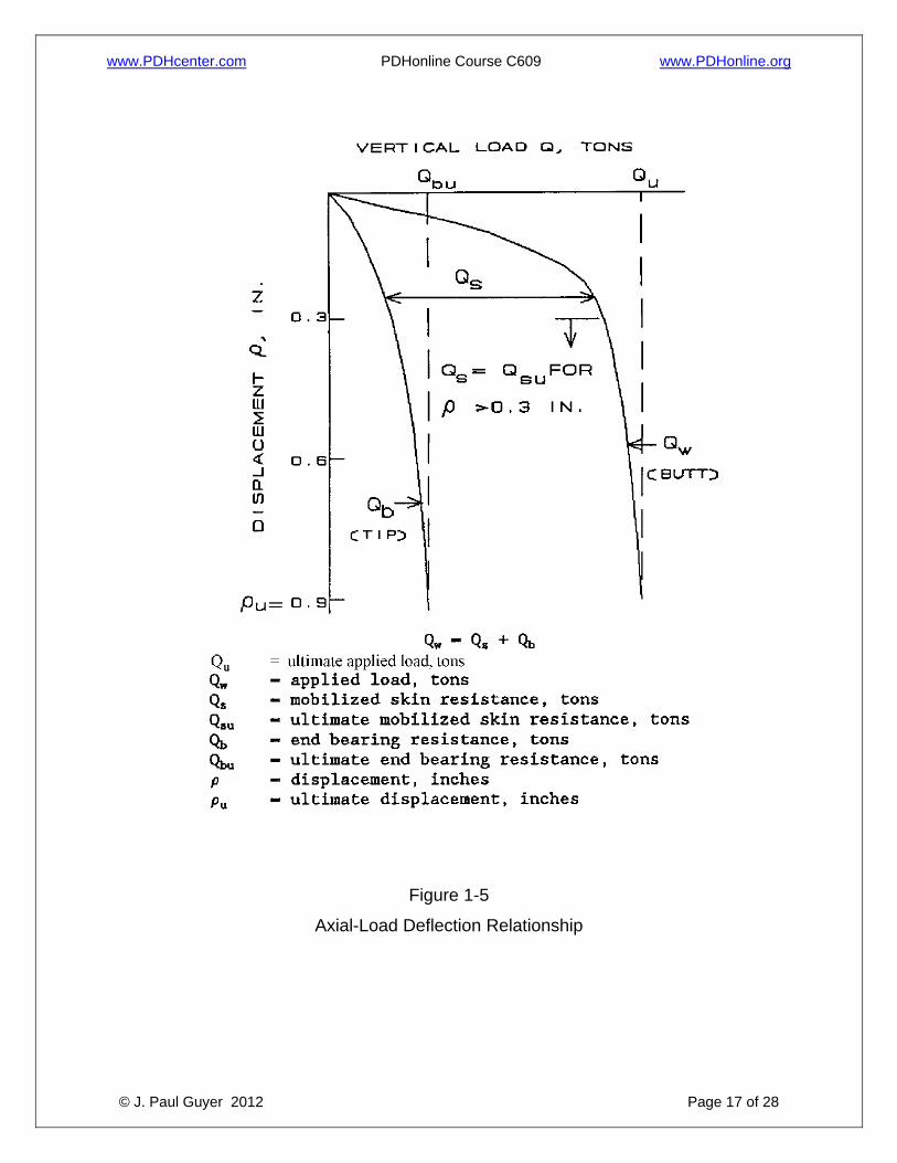
3.2.2 SKIN RESISTANCE MOBILIZATION. Full skin resistance is typically mobilized
within 0.5 inch of displacement, while end bearing may not be fully mobilized until
displacements exceed 10 to 20 percent of the base diameter or under-ream for drilled
shafts, unless the tip is supported by stiff clay, dense sand, or rock. Figure1-5 illustrates
an example of the vertical axial load displacement behavior of single pile or drilled shaft.
The load-displacement behavior and displacements that correspond to ultimate load are
site specific and depend on the results of analyses.
www.PDHcenter.com PDHonline Course C609 www.PDHonline.org
© J. Paul Guyer 2012 Page 16 of 28
3.2.3 LATERAL LOADS. Lateral load capacity of a pile or drilled shaft is directly
related to the diameter, thus increasing the diameter increases the load-carrying
capacity. For a drilled shaft that sustains no axial load, the cost of construction
Figure 1-4
Drilled shaft details
www.PDHcenter.com PDHonline Course C609 www.PDHonline.org
© J. Paul Guyer 2012 Page 17 of 28
Figure 1-5
Axial-Load Deflection Relationship
www.PDHcenter.com PDHonline Course C609 www.PDHonline.org
© J. Paul Guyer 2012 Page 18 of 28
may be optimized by the selection of rigid shafts without underreams and with
length/diameter ratios less than 10. The selected shaft dimensions should minimize the
volume of concrete required and maximize construction efficiency. The lateral load
capacity of driven piles may be increased by increasing the number of piles and
battering piles in a pile group. Batter piles are efficient in resisting lateral loads but
significantly reduce ductility of the pile group in the lateral direction, resulting in a brittle
failure. Vertical piles , though less efficient in resisting lateral loads, are also less stiff
and do not fail suddenly. These conflicting characteristics need to be balanced in
design, and they are considered critical where seismic or dynamic lateral loads are
involved.
3.3 APPLICATIONS. Driven pile groups are frequently used to support locks, dry
docks, and other facilities constructed in river systems, lakes, lagoons, and other
offshore applications. Drilled shafts typically support many permanent onshore
structures such as administrative buildings, warehouses, and health care facilities.
Drilled shafts are divided into two groups: displacement and nondisplacement.
3.3.1 DISPLACEMENT. Driven pile foundations are usually preferable in loose,
cohesionless, and soft soils, especially where excavations cannot support fluid concrete
and where the depth of the bearing stratum is uncertain. Groundwater conditions can be
a deciding factor in the selection of driven piles rather than drilled shafts. Uncased
shafts are generally excluded from consideration where artesian pressures are present.
Often more than one type of driven pile may meet all requirements for a particular
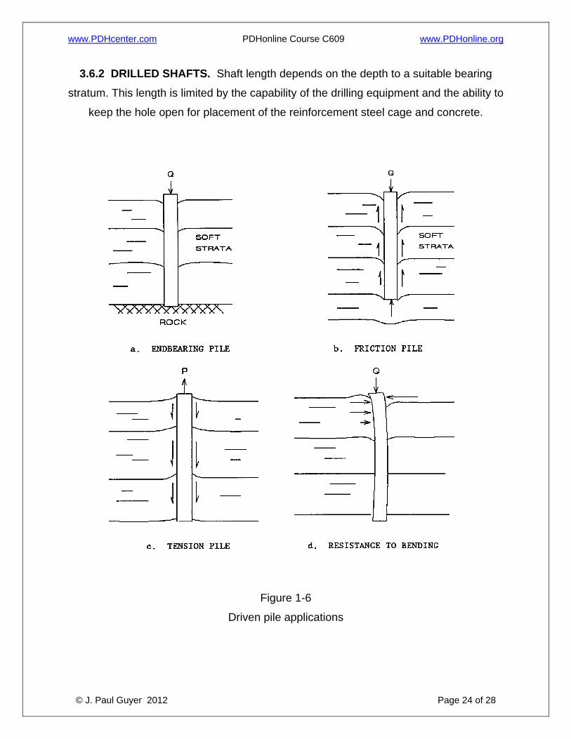
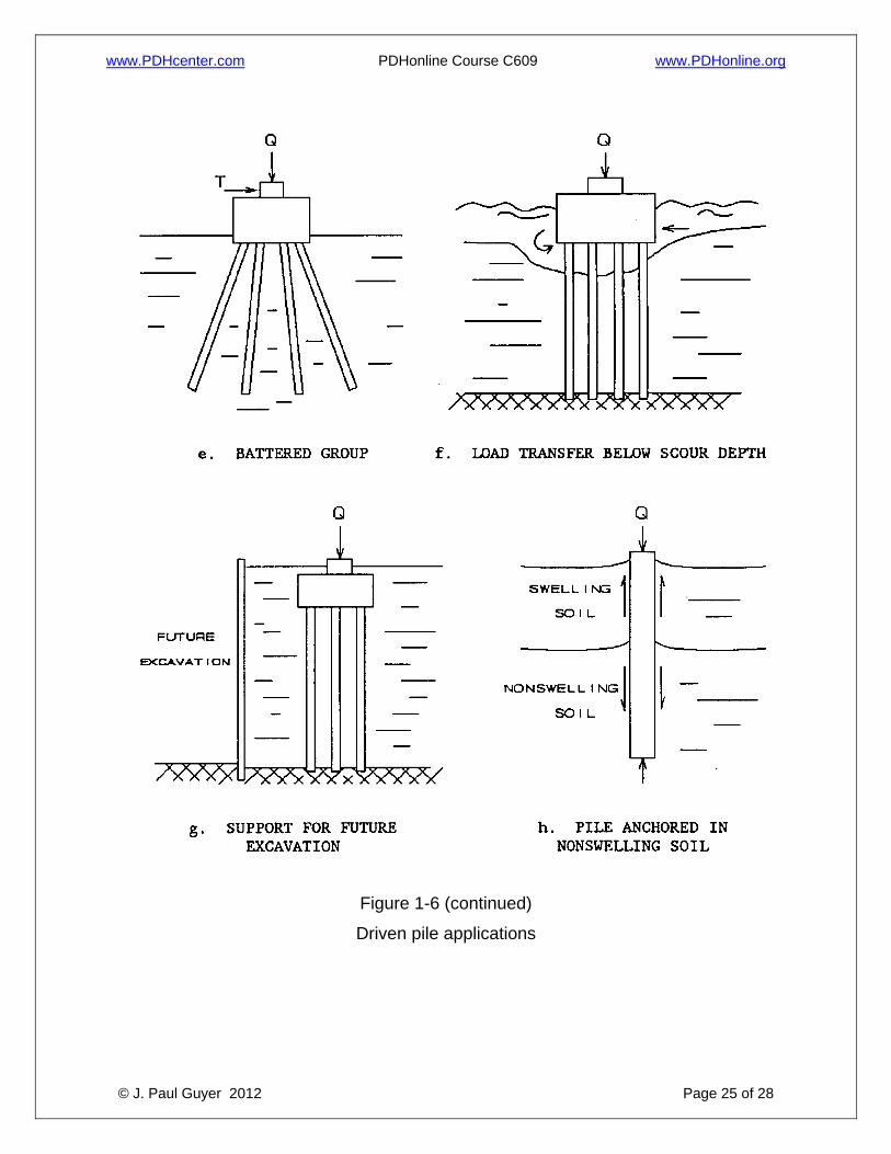
structure. Driven piles according to their application are presented in Figure 1-6.
3.3.1.1 Figures 1-6a and 1-6b illustrate piles classified according to their behavior as
end-bearing or friction piles. A pile embedded a significant length into stiff clays, silts,
and dense sands without significant end bearing resistance is usually a friction pile. A
pile driven through relatively weak or compressible soil to an underlying stronger soil or
rock is usually an end-bearing pile.
www.PDHcenter.com PDHonline Course C609 www.PDHonline.org
© J. Paul Guyer 2012 Page 19 of 28
3.3.1.2 Piles designed primarily to resist upward forces are uplift or tension piles
(Figure 1-6c), and the resistance to the upward force is by a combination of side (skin)
friction and self weight of the pile.
3.3.1.3 Lateral forces are resisted either by vertical piles in bending (Figure 1-6d) or by
batter piles or groups of vertical and batter piles (Figure 1-6e).
3.3.1.4 Piles are used to transfer loads from above water structures to below the scour
depth (Figure 1-6f). Piles are also used to support structures that may be endangered
by future adjacent excavations (Figure1-6g). In order to prevent undesirable movements
of structures on shrink/swell soils, a pile anchored as shown in Figure 1-6h can be used.
3.3.2 NONDISPLACEMENT. Drilled shafts are especially suitable for supporting large
column loads of multistory structures and bridge abutments or piers. They are suitable
for resisting large axial loads and lateral load s applied to the shaft butt (top or head)
resulting from wind forces; these are also used for resisting uplift thrust applied to the
shaft perimeter through soil-shaft interface friction and from heave of expansive soil.
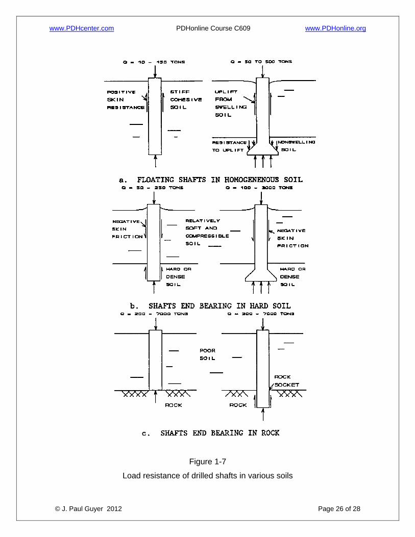
Figure 1-7 illustrates example load ranges for drilled shafts in different soils. The loads
shown are for guidance only and can vary widely from site to site. Cylindrical shafts are
usually preferred to under-reamed ones because of ease in construction and ease in
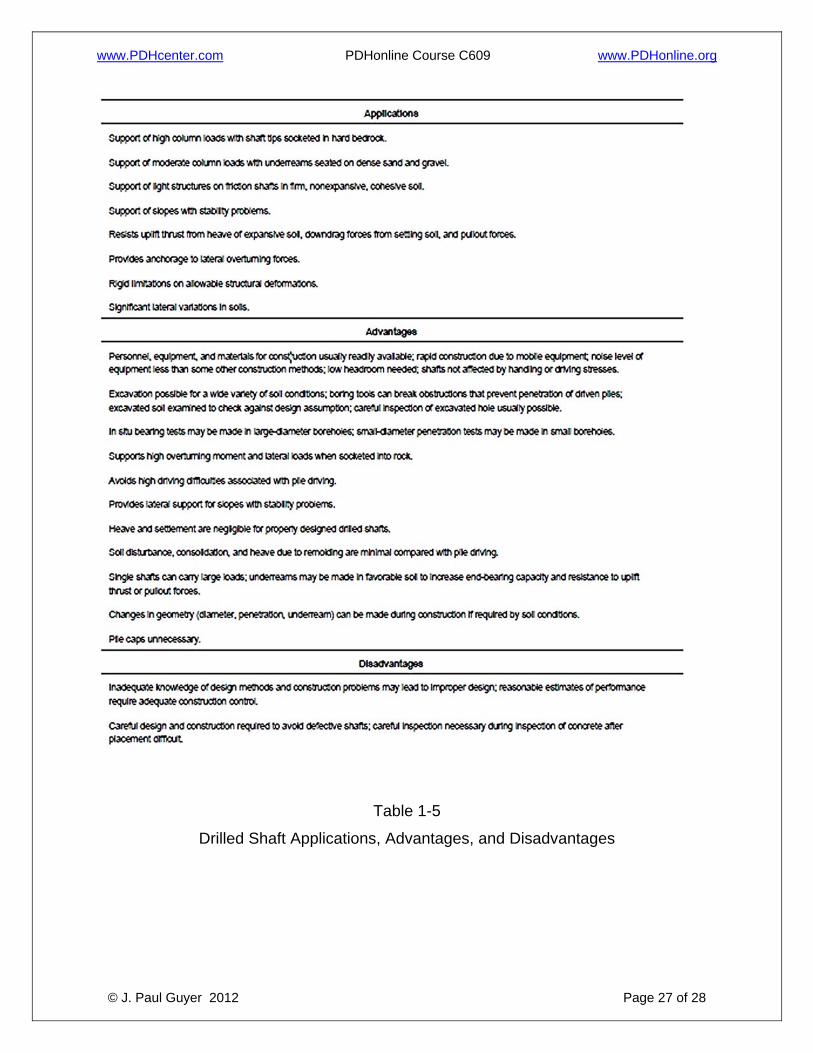
inspection. Table 1-5 provides further details of the applications, advantages, and
disadvantages of drilled shafts. Other aspects of drilled shafts include:
3.3.2.1 Drilled shafts may secure much or all of their vertical load capacity from frictional
side resistance (Figure1-7a). An enlarged base using a bell or underream may also
increase the vertical load capacity, provide uplift resistance to pullout loads, and resist
uplift thrust from heave of expansive soil. Shafts subject to pullout loads or uplift thrust
must have sufficient reinforcement steel to absorb the tension load in the shaft and
sufficient skin friction and underream resistance to prevent shaft uplift movements.
www.PDHcenter.com PDHonline Course C609 www.PDHonline.org
© J. Paul Guyer 2012 Page 20 of 28
Table 1-3
Standard H-piles
www.PDHcenter.com PDHonline Course C609 www.PDHonline.org
© J. Paul Guyer 2012 Page 21 of 28
3.3.2.2 The shaft may pass through relatively soft, compressible deposits and develop
vertical load capacity from end bearing on hard or dense granular soil (Fig. 1-7b) or rock
(Fig. 1-7c). End-bearing capacity should be sufficient to support vertical loads supplied
by the structure as well as any downdrag forces on the shaft perimeter caused by
negative skin friction from consolidating soil (Fig. 1-7b).
3.3.2.3 Single drilled shafts may be constructed with large diameters, typically 10 feet
or more, and can extend to depths of 200 feet or more. Drilled shafts can be made to
support large loads and are seldom constructed in closely spaced groups.
3.3.2.4 Drilled shafts tend to be preferred compared with driven piles as the soil
becomes harder. Pile driving becomes difficult in these cases, and the driving vibration
can adversely affect nearby structures. Also, many onshore areas have noise control
ordinances which prohibit 24-hour pile driving (a cost impact).
3.3.2.5 Good information on rock is required when drilled shafts are supported by rock.
Drilled shafts placed in weathered rock or that show lesser capacity than expected may
require shaft bases to be placed deeper than anticipated. This may cause significant
cost overruns.
3.4 LOCATION AND TOPOGRAPHY. Location and topography strongly influence
selection of the foundation. Local practice is usually an excellent guide. Driven piles are
often undesirable in congested urban locations because of noise, inadequate clearance
for pile driving, and the potential for damage caused by vibration, soil densification, and
ground heave. Prefabricated piles may also be undesirable if storage space is not
available. Other variables may restrict the utilization of deep foundation:
3.4.1 Access roads with limited bridge capacity and head room may restrict certain
piles and certain construction equipment.
www.PDHcenter.com PDHonline Course C609 www.PDHonline.org
© J. Paul Guyer 2012 Page 22 of 28
Table 1-4
Characteristics of Deep Foundations
www.PDHcenter.com PDHonline Course C609 www.PDHonline.org
© J. Paul Guyer 2012 Page 23 of 28
3.4.2 The cost of transporting construction equipment to the site may be significant for
small, isolated structures and may justify piles that can be installed using light, locally
available equipment.
3.5 ECONOMY. 3.5.1 DRIVEN PILES. Costs will depend on driving rig rental, local labor rates, fuel,
tools, supplies, cost and freight of pile materials, driving resistance, handling, cutoffs,
caps, splicing, and jetting. Jetting is the injection of water under pressure, usually from
jets located on opposite sides of the pile, to pre-excavate a hole and to assist pile
penetration. Costs are also influenced by downtime for maintenance and repairs,
insurance, overhead, and profit margin. An economic study should be made to
determine the cost/capacity ratio of the various types of piles. Consideration should be
given to including alternative designs in contract documents where practical.
3.5.2 DRILLED SHAFTS. Drilled shafts are usually cost effective in soil above the
water table and installation in cohesive soil, dense sand, rock, or other bearing soil
overlaid by cohesive soil that will not cave when the hole is bored. Drilled shafts,
particularly auger-placed, pressure-grouted shafts, are often most economical if the hole
can be bored without slurry or casing.
3.6 LENGTH. The length of the deep foundation is generally dependent on topography
and soil conditions of the site.
3.6.1 DRIVEN PILES. Pile length is controlled by soil conditions and location of a
suitable bearing stratum, availability and suitability of driving equipment, total pile
offshore. Piles up to 150 feet are technically and economically acceptable for onshore
installation.
www.PDHcenter.com PDHonline Course C609 www.PDHonline.org
© J. Paul Guyer 2012 Page 24 of 28
3.6.2 DRILLED SHAFTS. Shaft length depends on the depth to a suitable bearing
stratum. This length is limited by the capability of the drilling equipment and the ability to
keep the hole open for placement of the reinforcement steel cage and concrete.
Figure 1-6
Driven pile applications
www.PDHcenter.com PDHonline Course C609 www.PDHonline.org
© J. Paul Guyer 2012 Page 25 of 28
Figure 1-6 (continued)
Driven pile applications
www.PDHcenter.com PDHonline Course C609 www.PDHonline.org
© J. Paul Guyer 2012 Page 26 of 28
Figure 1-7
Load resistance of drilled shafts in various soils
www.PDHcenter.com PDHonline Course C609 www.PDHonline.org
© J. Paul Guyer 2012 Page 27 of 28
Table 1-5
Drilled Shaft Applications, Advantages, and Disadvantages
www.PDHcenter.com PDHonline Course C609 www.PDHonline.org
© J. Paul Guyer 2012 Page 28 of 28
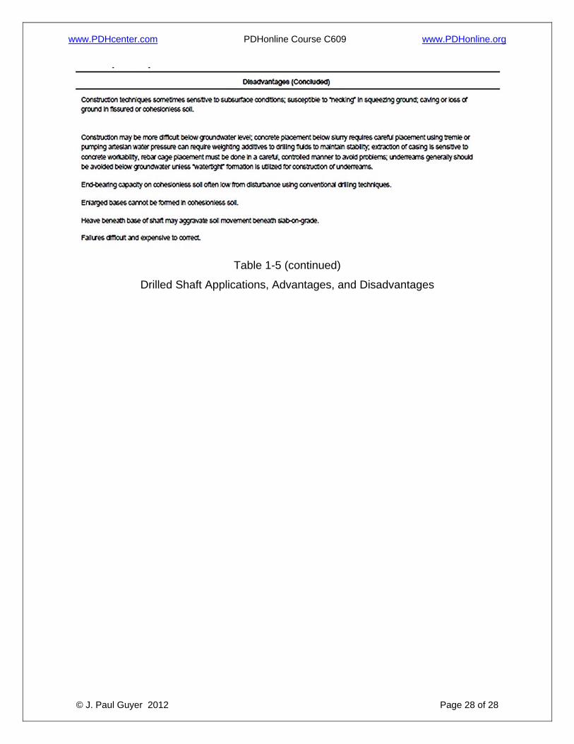
Table 1-5 (continued)
Drilled Shaft Applications, Advantages, and Disadvantages