pile foundations - uoanbar.edu.iq
TRANSCRIPT
PILE FOUNDATION
University of Anbar
Engineering College
Civil Engineering Department
Chapter SIX
PILE Foundations
Lecture
Dr. Ahmed H. Abdulkareem
2019 - 2020
PILE FOUNDATION
6.1. Introduction
Piles are structural members that are made of steel, concrete, or timber.
They are used to build pile foundations, which are deep and which cost
more than shallow foundations. Despite the cost, the use of piles often is
necessary to ensure structural safety. The following list identifies some of
the conditions that require pile foundations (Vesic, 1977):
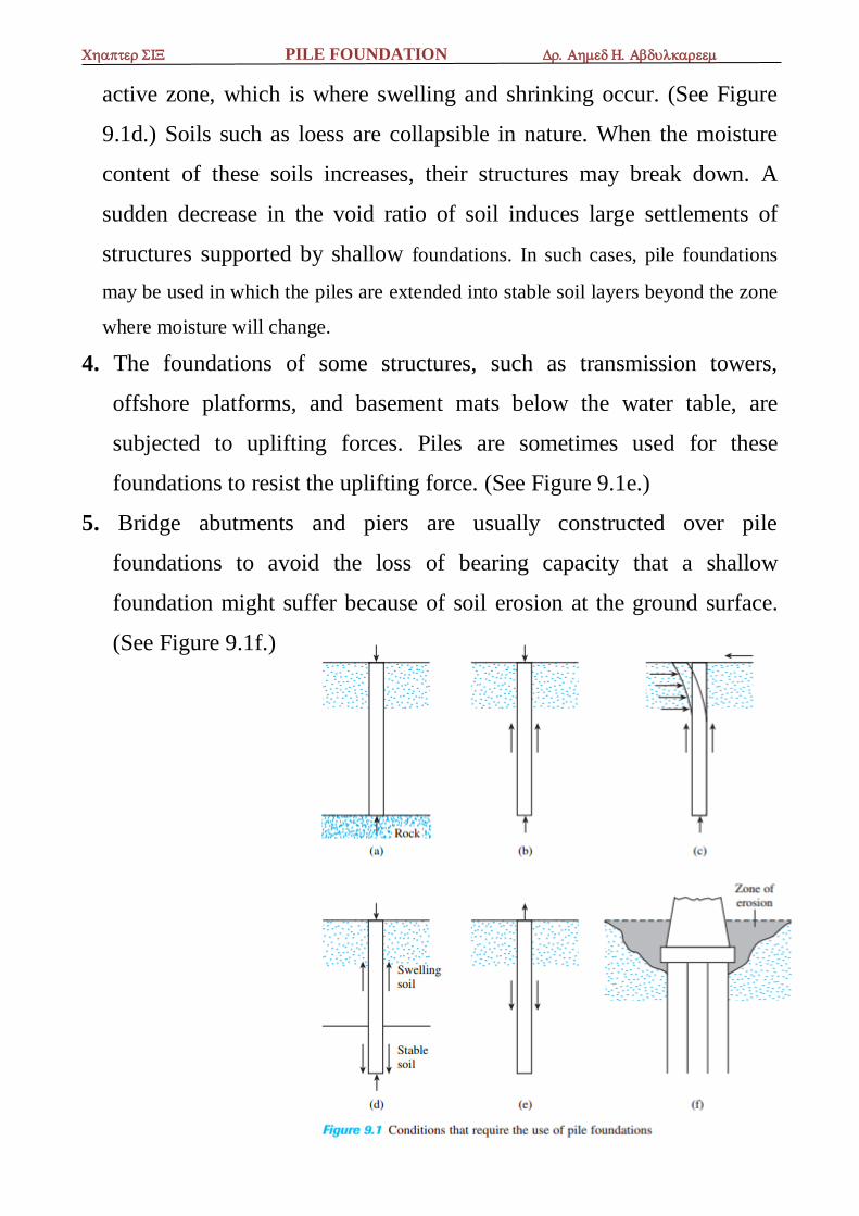
1. When one or more upper soil layers are highly compressible and too
weak to support the load transmitted by the superstructure, piles are used
to transmit the load to underlying bedrock or a stronger soil layer, as
shown in Figure 9.1a. When bedrock is not encountered at a reasonable
depth below the ground surface, piles are used to transmit the structural
load to the soil gradually. The resistance to the applied structural load is
derived mainly from the frictional resistance developed at the soil–pile
interface. (See Figure 9.1b.)
2. When subjected to horizontal forces (see Figure 9.1c), pile foundations
resist by bending, while still supporting the vertical load transmitted by
the superstructure. This type of situation is generally encountered in the
design and construction of earth-retaining structures and foundations of
tall structures that are subjected to high wind or to earthquake forces.
3. In many cases, expansive and collapsible soils may be present at the site
of a proposed structure. These soils may extend to a great depth below
the ground surface. Expansive soils swell and shrink as their moisture
content increases and decreases, and the pressure of the swelling can be
considerable. If shallow foundations are used in such circumstances, the
structure may suffer considerable damage. However, pile foundations
may be considered as an alternative when piles are extended beyond the
PILE FOUNDATION
active zone, which is where swelling and shrinking occur. (See Figure
9.1d.) Soils such as loess are collapsible in nature. When the moisture
content of these soils increases, their structures may break down. A
sudden decrease in the void ratio of soil induces large settlements of
structures supported by shallow foundations. In such cases, pile foundations
may be used in which the piles are extended into stable soil layers beyond the zone
where moisture will change.
4. The foundations of some structures, such as transmission towers,
offshore platforms, and basement mats below the water table, are
subjected to uplifting forces. Piles are sometimes used for these
foundations to resist the uplifting force. (See Figure 9.1e.)
5. Bridge abutments and piers are usually constructed over pile
foundations to avoid the loss of bearing capacity that a shallow
foundation might suffer because of soil erosion at the ground surface.
(See Figure 9.1f.)
PILE FOUNDATION
9.2 Types of Piles and Their Structural Characteristics
Different types of piles are used in construction work, depending on
the type of load to be carried, the subsoil conditions, and the location
of the water table.
Piles can be divided into the following categories with the general
descriptions for conventional steel, concrete, timber, and composite
piles.
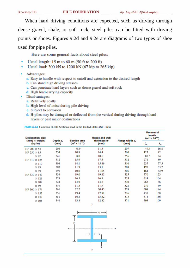
Steel Piles
Steel piles generally are either pipe piles or rolled steel H-section
piles.
Pipe piles can be driven into the ground with their ends open or
closed.
Wide-flange and I-section steel beams can also be used as piles.
However, H-section piles are usually preferred because their web and
flange thicknesses are equal. (In wide-flange and I-section beams, the
web thicknesses are smaller than the thicknesses of the flange.) Table
9.1 gives the dimensions of some standard H-section steel piles used
in the United States.
Table 9.2 shows selected pipe sections frequency used for piling
purposes.
In many cases, the pipe piles are filled with concrete after they have
been driven.
The allowable structural capacity for steel piles is
PILE FOUNDATION
When hard driving conditions are expected, such as driving through
dense gravel, shale, or soft rock, steel piles can be fitted with driving
points or shoes. Figures 9.2d and 9.2e are diagrams of two types of shoe
used for pipe piles.
PILE FOUNDATION
PILE FOUNDATION
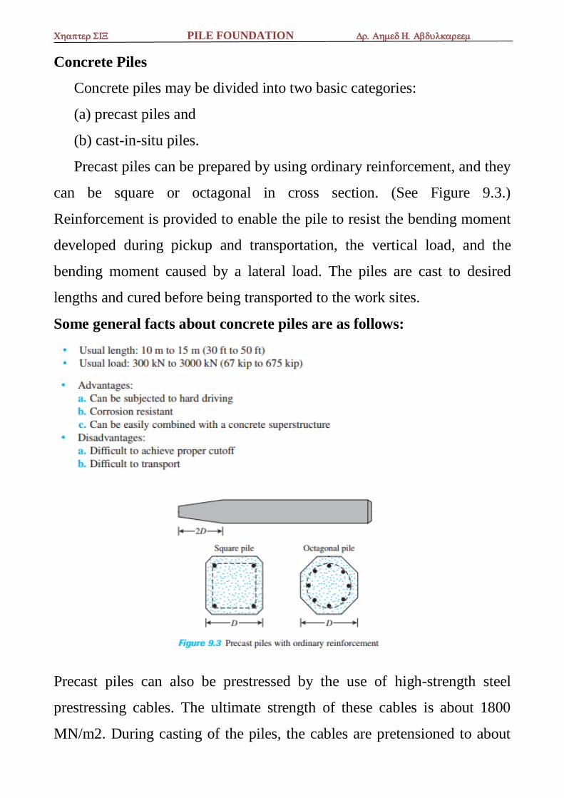
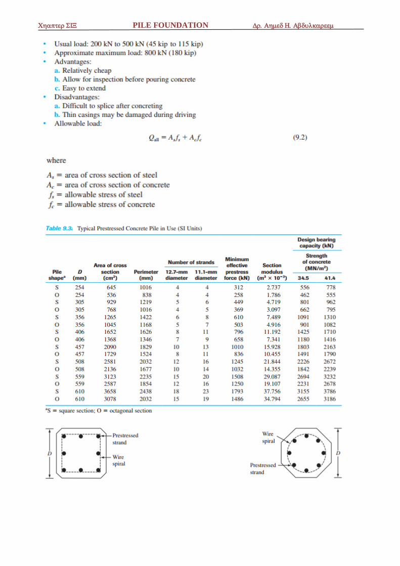
Concrete Piles
Concrete piles may be divided into two basic categories:
(a) precast piles and
(b) cast-in-situ piles.
Precast piles can be prepared by using ordinary reinforcement, and they
can be square or octagonal in cross section. (See Figure 9.3.)
Reinforcement is provided to enable the pile to resist the bending moment
developed during pickup and transportation, the vertical load, and the
bending moment caused by a lateral load. The piles are cast to desired
lengths and cured before being transported to the work sites.
Some general facts about concrete piles are as follows:
Precast piles can also be prestressed by the use of high-strength steel
prestressing cables. The ultimate strength of these cables is about 1800
MN/m2. During casting of the piles, the cables are pretensioned to about
PILE FOUNDATION
900 to 1300 MN/m2, and concrete is poured around them. After curing,
the cables are cut, producing a compressive force on the pile section. Table
9.3 gives additional information about prestressed concrete piles with
square and octagonal cross sections.
Some general facts about precast prestressed piles are as follows:
Cast-in-situ, or cast-in-place, piles are built by making a hole in the
ground and then filling it with concrete. Various types of cast-in-place
concrete piles are currently used in construction, and most of them have
been patented by their manufacturers. These piles may be divided into two
broad categories: (a) cased and (b) uncased. Both types may have a
pedestal at the bottom.
Cased piles are made by driving a steel casing into the ground with the
help of a mandrel placed inside the casing. When the pile reaches the
proper depth the mandrel is withdrawn and the casing is filled with
concrete. Figures 9.4a, 9.4b, 9.4c, and 9.4d show some examples of cased
piles without a pedestal. Figure 9.4e shows a cased pile with a pedestal.
The pedestal is an expanded concrete bulb that is formed by dropping a
hammer on fresh concrete.
Some general facts about cased cast-in-place piles are as follows:
PILE FOUNDATION

PILE FOUNDATION
Figures 9.4f and 9.4g are two types of uncased pile, one with a pedestal
and the other without. The uncased piles are made by first driving the
casing to the desired depth and then filling it with fresh concrete. The
casing is then gradually withdrawn. Following are some general facts
about uncased cast-in-place concrete piles:
PILE FOUNDATION
Timber Piles
Timber piles are tree trunks that have had their branches and bark
carefully trimmed off. The maximum length of most timber piles is 10 to
20 m (30 to 65 ft). To qualify for use as a pile, the timber should be
straight, sound, and without any defects. The American Society of Civil
Engineers’ Manual of Practice, No. 17 (1959), divided timber piles into
three classes:
1. Class A piles carry heavy loads. The minimum diameter of the butt
should be 356 mm (14 in.).
2. Class B piles are used to carry medium loads. The minimum butt
diameter should be 305 to 330 mm (12 to 13 in.).
3. Class C piles are used in temporary construction work. They can be
used permanently for structures when the entire pile is below the water
table. The minimum butt diameter should be 305 mm (12 in.).
In any case, a pile tip should not have a diameter less than 150 mm.
Timber piles cannot withstand hard driving stress; therefore, the pile
capacity is generally limited. Steel shoes may be used to avoid damage at
the pile tip (bottom). The tops of timber piles may also be damaged during
the driving operation. The crushing of the wooden fibers caused by the
impact of the hammer is referred to as brooming. To avoid damage to the
top of the pile, a metal band or a cap may be used.
PILE FOUNDATION
Composite Piles
The upper and lower portions of composite piles are made of different
materials. For example, composite piles may be made of steel and concrete
or timber and concrete. Steel-and-concrete piles consist of a lower portion
of steel and an upper portion of cast-inplace concrete. This type of pile is
used when the length of the pile required for adequate bearing exceeds the
capacity of simple cast-in-place concrete piles. Timber-and-concrete piles
usually consist of a lower portion of timber pile below the permanent
water table and an upper portion of concrete. In any case, forming proper
joints between two dissimilar materials is difficult, and for that reason,
composite piles are not widely used.
6.4 Estimating Pile Length
Selecting the type of pile to be used and estimating its necessary length
are fairly difficult tasks that require good judgment. In addition to being
broken down into the classification given in Section 6.2, piles can be
divided into three major categories, depending on their lengths and the
mechanisms of load transfer to the soil:
(a) point bearing piles,
(b) friction piles, and
(c) compaction piles.
a. Point Bearing Piles
If soil-boring records establish the presence of bedrock or rocklike
material at a site within a reasonable depth, piles can be extended to the
rock surface. (See Figure 9.6a.) In this case, the ultimate capacity of the
piles depends entirely on the load-bearing capacity of the underlying
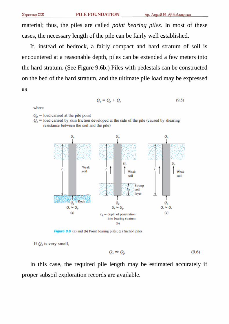
PILE FOUNDATION
material; thus, the piles are called point bearing piles. In most of these
cases, the necessary length of the pile can be fairly well established.
If, instead of bedrock, a fairly compact and hard stratum of soil is
encountered at a reasonable depth, piles can be extended a few meters into
the hard stratum. (See Figure 9.6b.) Piles with pedestals can be constructed
on the bed of the hard stratum, and the ultimate pile load may be expressed
as
In this case, the required pile length may be estimated accurately if
proper subsoil exploration records are available.
PILE FOUNDATION
b- Friction Piles
When no layer of rock or rocklike material is present at a reasonable
depth at a site, point bearing piles become very long and uneconomical. In
this type of subsoil, piles are driven through the softer material to specified
depths. (See Figure 9.6c.) The ultimate load of the piles may be expressed
by Eq. (9.5). However, if the value of Qp is relatively small, then
These piles are called friction piles, because most of their resistance is
derived from skin friction. However, the term friction pile, although used
often in the literature, is a misnomer: In clayey soils, the resistance to
applied load is also caused by adhesion.
The lengths of friction piles depend on the shear strength of the soil, the
applied load, and the pile size. To determine the necessary lengths of these
piles, an engineer needs a good understanding of soil–pile interaction,
good judgment, and experience.
c- Compaction Piles
Under certain circumstances, piles are driven in granular soils to
achieve proper compaction of soil close to the ground surface. These piles
are called compaction piles. The lengths of compaction piles depend on
factors such as
(a) the relative density of the soil before compaction,
(b) the desired relative density of the soil after compaction, and
(c) the required depth of compaction.
These piles are generally short; however, some field tests are necessary
to determine a reasonable length.
PILE FOUNDATION
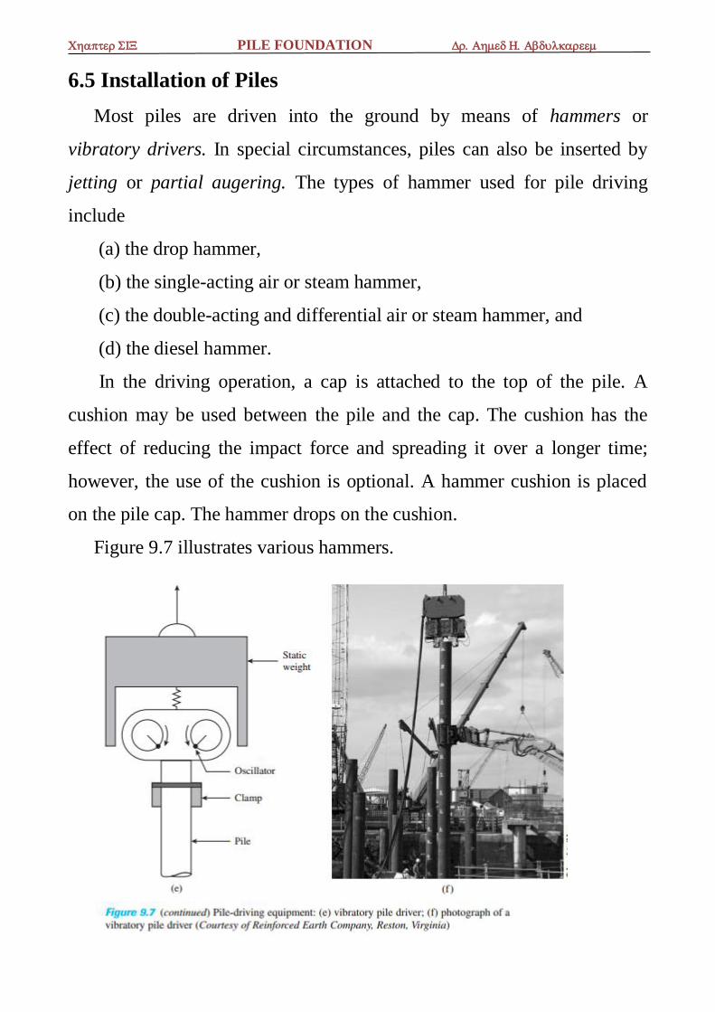
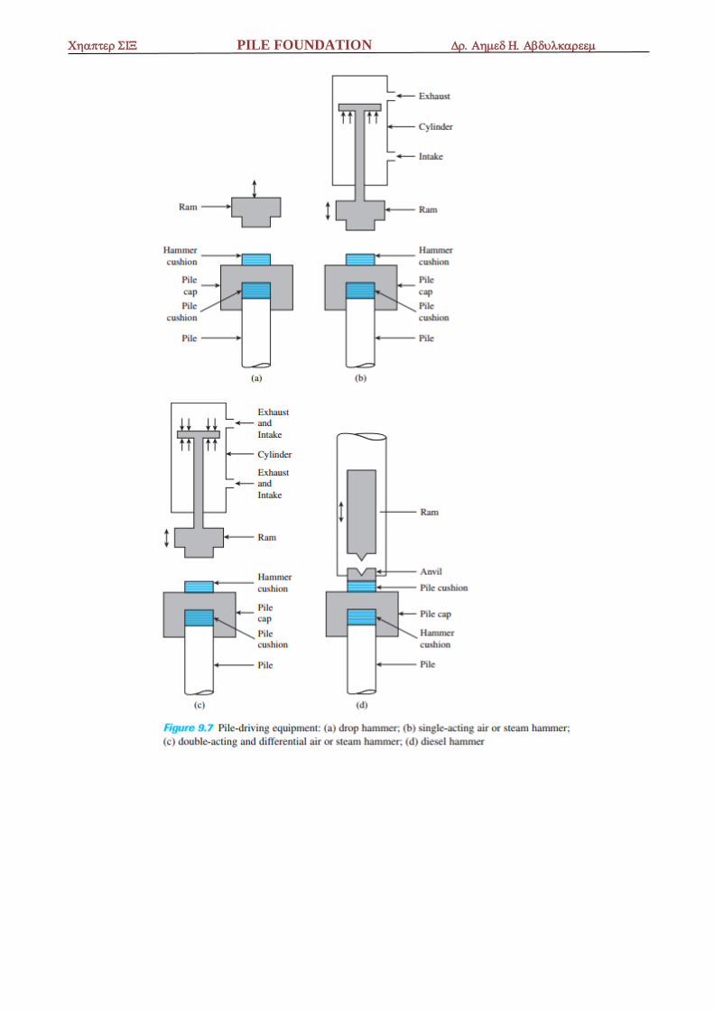
6.5 Installation of Piles
Most piles are driven into the ground by means of hammers or
vibratory drivers. In special circumstances, piles can also be inserted by
jetting or partial augering. The types of hammer used for pile driving
include
(a) the drop hammer,
(b) the single-acting air or steam hammer,
(c) the double-acting and differential air or steam hammer, and
(d) the diesel hammer.
In the driving operation, a cap is attached to the top of the pile. A
cushion may be used between the pile and the cap. The cushion has the
effect of reducing the impact force and spreading it over a longer time;
however, the use of the cushion is optional. A hammer cushion is placed
on the pile cap. The hammer drops on the cushion.
Figure 9.7 illustrates various hammers.
PILE FOUNDATION
PILE FOUNDATION
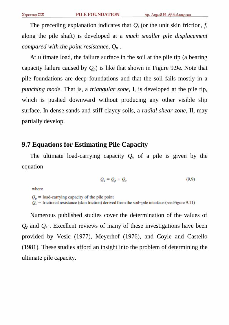
6.6 Load Transfer Mechanism
The load transfer mechanism from a pile to the soil is complicated. To
understand it, consider a pile of length L, as shown in Figure 9.9a. The
load on the pile is gradually increased from zero to Q(z=0) at the ground
surface. Part of this load will be resisted by the side friction developed
along the shaft, Q1 , and part by the soil below the tip of the pile, Q2 . Now,
how are Q1 and Q2 related to the total load? If measurements are made to
obtain the load carried by the pile shaft, Q(z) , at any depth z, the nature of
the variation found will be like that shown in curve 1 of Figure 9.9b. The
frictional resistance per unit area at any depth z may be determined as
Where
p = perimeter of the cross section of the pile. Figure 9.9c shows the
variation of f(z) with depth.
If the load Q at the ground surface is gradually increased, maximum
frictional resistance along the pile shaft will be fully mobilized when the
relative displacement between the soil and the pile is about 5 to 10 mm
,irrespective of the pile size and length L. However, the maximum point
resistance Q2 = Qp will not be mobilized until the tip of the pile has moved
about 10 to 25% of the pile width (or diameter). (The lower limit applies to
driven piles and the upper limit to bored piles). At ultimate load (Figure
9.9d and curve 2 in Figure 9.9b), Q(z=0) = Qu . Thus,
Q1 = Qs
and
Q2 = Qp
PILE FOUNDATION
The preceding explanation indicates that Qs (or the unit skin friction, f,
along the pile shaft) is developed at a much smaller pile displacement
compared with the point resistance, Qp .
At ultimate load, the failure surface in the soil at the pile tip (a bearing
capacity failure caused by Qp) is like that shown in Figure 9.9e. Note that
pile foundations are deep foundations and that the soil fails mostly in a
punching mode. That is, a triangular zone, I, is developed at the pile tip,
which is pushed downward without producing any other visible slip
surface. In dense sands and stiff clayey soils, a radial shear zone, II, may
partially develop.
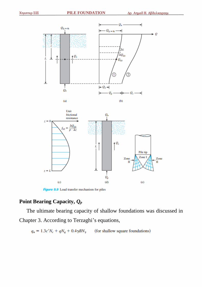
9.7 Equations for Estimating Pile Capacity
The ultimate load-carrying capacity Qu of a pile is given by the
equation
Numerous published studies cover the determination of the values of
Qp and Qs . Excellent reviews of many of these investigations have been
provided by Vesic (1977), Meyerhof (1976), and Coyle and Castello
(1981). These studies afford an insight into the problem of determining the
ultimate pile capacity.
PILE FOUNDATION
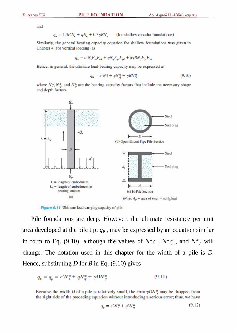
Point Bearing Capacity, Qp
The ultimate bearing capacity of shallow foundations was discussed in
Chapter 3. According to Terzaghi’s equations,
PILE FOUNDATION
Pile foundations are deep. However, the ultimate resistance per unit
area developed at the pile tip, qp , may be expressed by an equation similar
in form to Eq. (9.10), although the values of N*c , N*q , and N* will
change. The notation used in this chapter for the width of a pile is D.
Hence, substituting D for B in Eq. (9.10) gives
PILE FOUNDATION
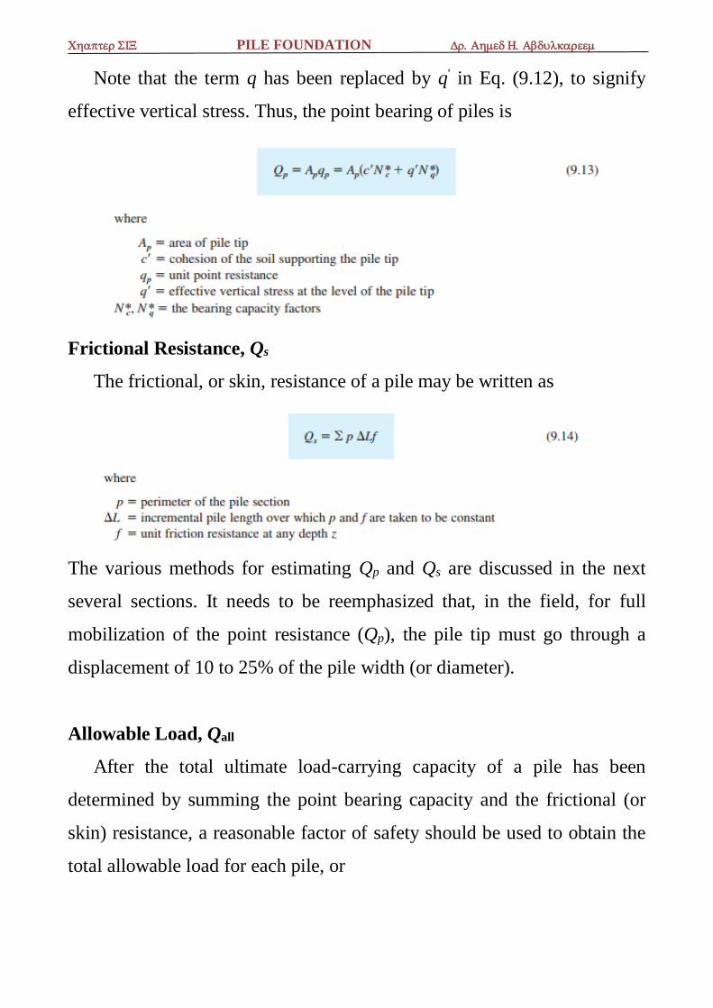
Note that the term q has been replaced by q' in Eq. (9.12), to signify
effective vertical stress. Thus, the point bearing of piles is
Frictional Resistance, Qs
The frictional, or skin, resistance of a pile may be written as
The various methods for estimating Qp and Qs are discussed in the next
several sections. It needs to be reemphasized that, in the field, for full
mobilization of the point resistance (Qp), the pile tip must go through a
displacement of 10 to 25% of the pile width (or diameter).
Allowable Load, Qall
After the total ultimate load-carrying capacity of a pile has been
determined by summing the point bearing capacity and the frictional (or
skin) resistance, a reasonable factor of safety should be used to obtain the
total allowable load for each pile, or
PILE FOUNDATION
The factor of safety generally used ranges from 2.5 to 4, depending on
the uncertainties surrounding the calculation of ultimate load.
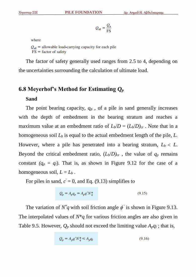
6.8 Meyerhof’s Method for Estimating Qp
Sand
The point bearing capacity, qp , of a pile in sand generally increases
with the depth of embedment in the bearing stratum and reaches a
maximum value at an embedment ratio of Lb/D = (Lb/D)cr . Note that in a
homogeneous soil Lb is equal to the actual embedment length of the pile, L.
However, where a pile has penetrated into a bearing stratum, Lb L.
Beyond the critical embedment ratio, (Lb/D)cr , the value of qp remains
constant (qp = ql). That is, as shown in Figure 9.12 for the case of a
homogeneous soil, L = Lb .
For piles in sand, c' = 0, and Eq. (9.13) simplifies to
The variation of N*q with soil friction angle ' is shown in Figure 9.13.
The interpolated values of N*q for various friction angles are also given in
Table 9.5. However, Qp should not exceed the limiting value Apql ; that is,
PILE FOUNDATION
PILE FOUNDATION
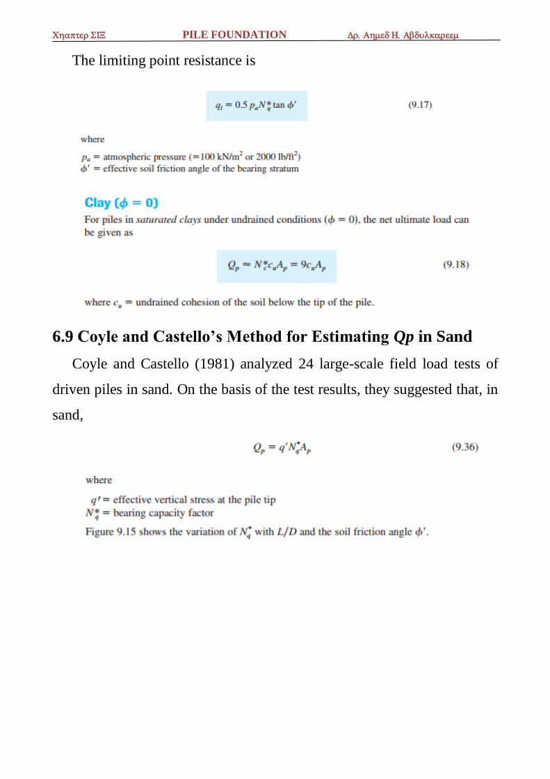
The limiting point resistance is
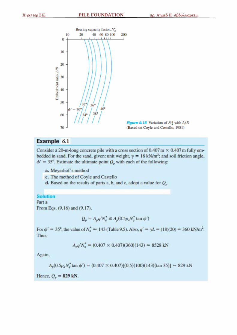
6.9 Coyle and Castello’s Method for Estimating Qp in Sand
Coyle and Castello (1981) analyzed 24 large-scale field load tests of
driven piles in sand. On the basis of the test results, they suggested that, in
sand,
PILE FOUNDATION

PILE FOUNDATION
PILE FOUNDATION
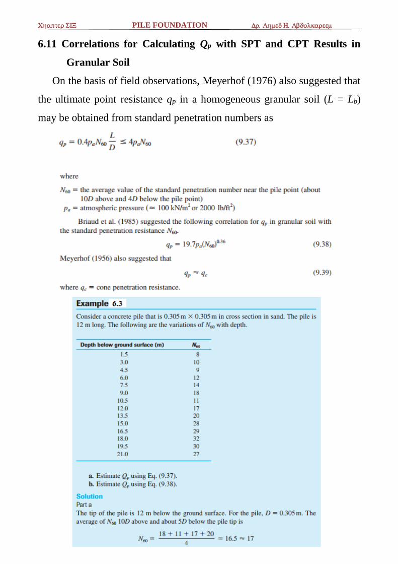
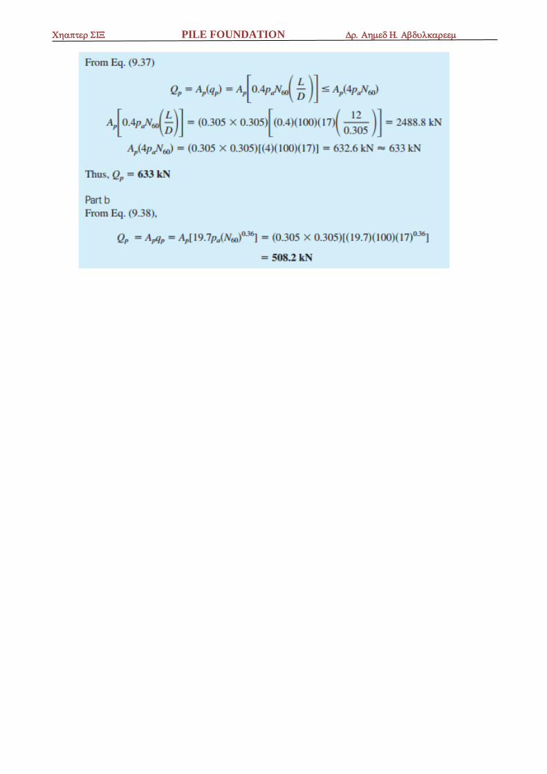
6.11 Correlations for Calculating Qp with SPT and CPT Results in
Granular Soil
On the basis of field observations, Meyerhof (1976) also suggested that
the ultimate point resistance qp in a homogeneous granular soil (L = Lb)
may be obtained from standard penetration numbers as
PILE FOUNDATION

PILE FOUNDATION

PILE FOUNDATION

PILE FOUNDATION

PILE FOUNDATION
PILE FOUNDATION
\
Figure 3.5 A small enclosure with steel sheet piles for an excavation work (Courtesy
of N. Sivakugan, James Cook University, Australia)
Table 3.1 Properties of Some Sheet-Pile Sections Production by Bethlehem Steel
Corporation

PILE FOUNDATION
Example 3.4:

PILE FOUNDATION