an introduction to automatic optical inspection (aoi) · in comparator mode a “golden board” is...
TRANSCRIPT

Introduction to Automatic Inspection Page 1 of 12
An Introduction to Automatic Optical Inspection (AOI)
Process Analysis
The following script has been prepared by DCB Automation to give more information to organisations who are considering the use of Automatic Optical Inspection. Where possible we have tried to make the information non-machine specific. Due to the increasing complexity of assembled printed circuit boards and the demand by end users for fully inspected boards there is now an increasing requirement for automatic optical inspection on assembled boards. However for those assembly companies that are new to AOI there are many factors that should be considered and understood, even before looking at the products currently available.
Automatic Optical Inspection cannot build quality back into a completed board; it should be considered as the final facility of an assembly line and is there to confirm correct assembly and to ensure there are no random faults. It is important to ensure all the preceding assembly processes have been optimised and are working effectively. Consideration must then be given to the assembly line capacity, particularly associated with placement speed, board size, board mix and minimum component size. Finally, consideration must be given to the person or persons that will have responsibility for the systems operation. Line Capacity Will the AOI system be required to operate in line or will it be used as a stand alone product? This will be dependent on the type of manufacturing being undertaken. In line systems would only normally be used for assembly lines that are running the same product or products continually for several days. For batch quantities (say up to several 100) an off line approach may be more appropriate or possibly a magazine feeder as an alternative.
Introduction to Automatic Inspection Page 2 of 12
Board Size Most AOI systems will accept either single boards or panellised boards; however some systems may have issues on programming panellised boards particularly if they are inter-linked with one another. Board Mix For those companies manufacturing a considerable range of boards it is important there is an easy change over between inspection programs and that tooling within the AOI system is easy to adjust. Component Size Chip components such as resistors and capacitors are now available down to 01005 and IC leg pitches down to 0.3mm centres. Since solder inspection will be an important part of the inspection process the machine must have adequate resolution to accommodate such devices if they are being placed. Operating Inspection Systems There are 2 aspects that should be considered when operating an AOI system, programming of boards and carrying out inspection of assembled boards. The person responsible for programming of boards should have in depth assembly knowledge and be computer proficient. The person responsible for carrying out inspection tasks would need to be familiar with operating a computer and have some understanding of assembly particularly associated with solder quality. In practice when initially introduced the same person is often responsible for both functions.
Buzz Words As with most industries the optical inspection industry has many buzzwords. We sometimes use buzzwords in an attempt to confuse you; we work on the assumption that you have forgotten science subjects learnt at school as most of these words are associated with the camera and lens. The following information may be of assistance in understanding the phrases used. Resolution This is a measure of the physical size each pixel of the display monitor represents on the board. It is expressed in millionths of a metre and displayed as “µM”. One millimetre is equivalent to 1000µM, the smaller the resolution the higher the apparent magnification. For components down to 01005, 10µM is an ideal resolution; however the clarity of the displayed image is also dependent on the camera sensor, lens and monitor quality. Cameras We are all familiar with quoted sensor sizes on conventional cameras. For inspection purposes we have to consider not only the pixel cell count, but also the physical size of the sensor. A high cell count on a small sensor may well have problems with cross talk, (electronic noise) between cells and reduce the clarity of the

Introduction to Automatic Inspection Page 3 of 12
displayed image. Ideally we are looking for a physically large cell size. However a large sensor has an effect on the lens. Lenses Lenses must be selected to match the chosen camera and required optical performance. Conventional cameras use wide angle or telephoto lenses; a zoom lens is a particular type of telephoto lens. For general photography, image distortion would not be an issue, but for optical inspection image distortion will be a problem. Using a conventional lens, tall components will be distorted appearing more magnified, areas of the board will be shadowed by high components and adjacent images cannot be merged into one large image (stitching). Telecentric Lenses To eliminate distortion, and allow for the stitching of images telecentric lenses are used. Telecentric lenses
have a limited field of view and ensure parallel light from the object (in our case this is the board under
inspection) is still parallel when it reaches the sensor of the camera.
Conventional Lens Telecentric Lens
Introduction to Automatic Inspection Page 4 of 12
Field of View This is the area of the board viewed by the camera. It is usually expressed in millimetres.
Depth of Field This is the distance from the board towards the lens that remains in focus.
Working Distance This is the maximum distance between the lens and board.
Models These are discussed in detail later, but a model is simply a visual representation of the data used in the computer analysis of a component. Topography Analysis (Sometimes claimed to be 3D Technology) To facilitate component imaging, LED arrays are normally used. By using a combination of colour rings set at different angles to the board being inspected, it is possible to generate a colour gradient of the solder fillet. This is generally what is referred to as Topography (and sometimes 3D) analysis.
Automatic Optical Inspection Platforms
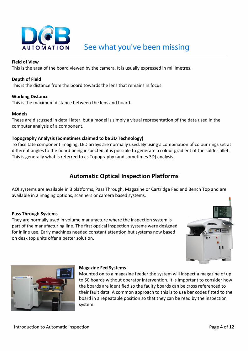
AOI systems are available in 3 platforms, Pass Through, Magazine or Cartridge Fed and Bench Top and are available in 2 imaging options, scanners or camera based systems. Pass Through Systems They are normally used in volume manufacture where the inspection system is part of the manufacturing line. The first optical inspection systems were designed for inline use. Early machines needed constant attention but systems now based on desk top units offer a better solution.
Magazine Fed Systems Mounted on to a magazine feeder the system will inspect a magazine of up to 50 boards without operator intervention. It is important to consider how the boards are identified so the faulty boards can be cross referenced to their fault data. A common approach to this is to use bar codes fitted to the board in a repeatable position so that they can be read by the inspection system.

Introduction to Automatic Inspection Page 5 of 12
Bench Top Systems As the name implies the inspection system is mounted on a bench in a convenient location to production. Boards or panels are loaded and unloaded individually with faults being either checked locally at the machine or fault data being down loaded to a rework station. This type of system gives the most versatile approach to inspection. With the above alternatives both camera based systems and scanner systems are available. Scanner Systems Line scan cameras are used to image boards for inspection using similar techniques to conventional office scanners. Generally scanner based systems have limitations on component size and the quality of solder inspection. For the remainder of this script scanner systems will be ignored, as they should be considered as a short-term solution to a continuing requirement Camera Based Systems Inspection systems employing cameras offer the best approach to the inspection process. They allow flexibility in the lighting techniques employed and achievable resolution. The various aspects associated with camera choice and illumination is discussed later.
Data Requirements
All automatic inspection systems will require detailed information for the boards being inspected. We would recommend prime data generated at board design. Most PCB Cad packages will output text files containing component identification, X and Y coordinates, rotation and placement side. We appreciate that often this information is not easily available. As an alternative, placement data from the SM placing machine can be used. However it must be remembered that if a mistake has been made when programming the placer this error will be replicated on the inspection machine. In addition data will be required linking component identification to unique component part numbers. This information will generally be obtained from parts lists.
Available Facilities In addition to the software for automatic inspection, consideration should also be given to additional features that would be of benefit to the user and possible specific requirements the user would like. Lasers

Introduction to Automatic Inspection Page 6 of 12
When fitted with a laser the user is able to perform co-planarity checks to ensure component surfaces are on a parallel plane to the board surface. This is particularly important when mounting BGA products. Also where there is uncertainty on the soldering of IC legs, the laser can be used to verify they are correctly soldered. Conformal Coating Inspection The facility is available for the inspection of conformal coatings. We can check for both sprayed and non-sprayed areas. First-Off Inspection With placement data and parts lists, 1st off inspection can be rapidly carried out. This can often save considerable time when verifying first off’s. Comparator Mode Many bench top inspection systems were initially designed as comparator systems only. In comparator mode a “golden board” is compared with a board under test. This can be a useful technique for the inspection of a few boards.
Board Inspection To those new to automatic optical inspection, the initial processes for the generation of inspection programs may seem unduly complicated. New users often think that automatic inspection is just a variation of comparator inspection (see above), unfortunately this is not the case. For those users planning to introduce AOI in to their processes, consideration should be given, at an early stage, to those who will be responsible for its operation. It should ideally be someone who is familiar with surface mount components and placement, and have some computer knowledge. All the following information is based on facilities available with DCB Automation products. Other manufactures may not have the comprehensive facilities provided by DCB Automation. The first stage in the generation of an inspection program is to load images of the board under test and its associated data and line up data information with board images. We then have to construct models of each component being inspected. This can either be carried out on the inspection system or off line. The use of off line programming frees up the inspection machine to continue to inspect boards that have already been programmed. Model Concepts In terms of inspection, a model is a pictorial representation of a specific component combined with its associated attributes. For example, a chip resistor is a rectangular box with solder points at each end and a value on its body. The displayed image should look similar to the actual component. Each different component on the board will require its own model. For similar components only one model will be required

Introduction to Automatic Inspection Page 7 of 12
which will be associated through the parts list to all other similar components on that board. It may also be necessary to create alternative models for the same component. Again considering a chip resistor, a 10K value can be displayed as either 1002 or 103, in this case if both devices occur on the same board it will be necessary to create an alternative model. Solder areas are also created during the preparation of a model. This can either be done on screen or if Gerber data is available for pad layout, this can be loaded when board data is loaded and the solder areas will automatically be set. Associated with each model will be a set of pass parameters. While initially we would normally set them high, in practice it may be necessary to reduce the settings due to component quality or board layout. However care must be exercised when reducing pass scores so that faulty devices or poor solder are not accepted. Unfortunately there are no definitive settings that can be used for solder settings as it is dependent on your quality requirements. Image of component on board Solder Test Position Test Value Test
All test applied The above images show the actual models and test applied to a simple component. To help in the generation of models we have included a set of basic model formats which in many cases will only require the person generating the inspection program to draw a box around the component image displayed on screen. An inspection program is generated as component models are developed. When all the models are generated, the settings can be checked by inspecting the board used to generate the necessary models. If all the models are correct the board will pass. The inspection program should now be optimised by inspecting a small quantity of new boards (normally 3 or 4 should be sufficient) and adjusting settings to compensate for component quality and visual differences. However it must be remembered that pass scores should not be reduced to such an extent that faults are disguised. It is much safer to accept some false calls and clear them at the fault review stage. Production boards can now be inspected. Libraries

Introduction to Automatic Inspection Page 8 of 12
It is impossible to give timings for the preparation of inspection programs. A board with many components but all similar can be programmed very quickly but a board with a large number of different components may take some time to program. However to aid programming, libraries can be constructed. The more components within the library the faster programs can be prepared. Library information is automatically extracted during programming. If all the components on a board are held in a common library, programming will only take a few minutes. Ideally all components used in manufacture would have unique part numbers. Often manufacture’s part numbers are used, but one should be aware that identical parts from different suppliers’ will have different part numbers. Libraries can also be created for specific customers. There is no restriction to the number of libraries that can be created. Optimising Board Inspection After the preparation of an inspection program it will be necessary to optimise it, to reduce false calls. There are many factors affecting optimisation some of which may be due to component position, component clarity and acceptable solder quality. For ideal optimisation it will be necessary to inspect several boards. Again it must be emphasized that optimisation should only be carried out with care so that actual faults are not disguised by low pass scores. Another factor affecting performance could be due to the selection of a “poor” component for the initial model. If this is the case then the model for that component can be changed to a better component on a different board during optimisation. Board Identification Provision is included for the manual introduction of job and board number. This information is set at the time of inspection. If bar coding is in use then these can be read at the start of the inspection process. All data generated during the inspection will be associated with that identification number. Completed Inspection At the end of the inspection process, faults can either be reviewed at the inspection station or sent to an off line rework station. By performing rework off line, the inspection system can continue to inspect boards. All fault images together with the model image are stored for later assessment.
Reporting facilities A report is generated for every board displaying faults detailing the component identification, position and type of fault. Should the inspector decide to accept a fault, this is also recorded. This fault report can either be printed out at the machine or transferred to an off-line station. The report may also be stored for later reviews. In addition a variety of reports can be generated to suit the users. Generally for a company new to automatic inspection they will be of a simple nature, giving details of repetitive faults. By generating suitable reports, the user will be able to understand the areas of the manufacturing process that requires attention.
Introduction to Automatic Inspection Page 9 of 12
Laser Inspection When the AOI system is fitted with a laser, it is possible to check leg levels after soldering. This will compare leg heights to ensure they are all soldered correctly and flat to the board. The laser facility can always be requested to check leg heights on specific components or the inspection software decide if a laser check is required. In addition the laser can be used to prove co-planarity of BGA type products.
Production Inspection After completing the development and optimisation of an inspection program, the user is now ready to start the inspection of production boards. There are 2 approaches that can be used during inspection. Fault review at the Inspection Machine At the end of the inspection process a list of faults will be generated. These faults can be reviewed at the AOI system and either be accepted or reworked as appropriate. For rework, a local fault report can be generated and attached to the board. Accepted faults will not appear on this local report but will be kept on file for future reference. Off line fault Review At the end of the inspection process fault data is stored against a board number for later review and reworking if necessary. This information may be down loaded to a rework station where the operator is able to view the suspect area and compare this with the model used for inspection. The fault can be accepted but this action is still recorded. An important facility that is included on both our AOI and the off line software is the ability to re-apply tests on suspect components. This allows the operator to decide if the indicated fault can be accepted without detriment to the board’s integrity. It is important to note that on many systems this facility of comparing the master image with the suspect image is not available on off line programs.

Introduction to Automatic Inspection Page 10 of 12
Position Test Value Test Solder Test
While the position and value test performed on the above component are correct, the solder test is suspect. The displayed result indicates insufficient solder on some legs.
Factors affecting the Design of AOI systems Bench Top AOI equipment has developed over a period of some 12 years from simple comparator inspection systems to fully automatic inspection versions allowing for the smallest components to be verified. The advances of this type of inspection have been mainly due to improved computer, camera and lens technology. Mechanical Detail Most AOI systems will employ an X Y system to either position the camera, board or a combination of both. For pass through and magazine fed systems it will be the camera that is moved over the board. Linear motions usually driven by stepper motors are used for positioning. The footprint of the AOI system will be governed by the maximum board size that can be inspected. Camera and Lens Combination The choice of the camera and lens is a compromise determined by inspection speed, minimum component size and camera and lens resolution. For successful imaging the quality of the lens must match that of the

Introduction to Automatic Inspection Page 11 of 12
camera. The best images are obtained by the use of a telecentric lens with very low distortion and a large sensor which will eliminate “cross talk” between adjacent sensor elements. Working Distance, Depth of Field and Field of View The field of view is the area covered by a single image frame, the depth of field is the distance from the board to the highest component that is still in focus and the working height is the maximum height that can inspected by the system. It will probably be that tall items will not be in focus. The field of view and depth of field are again functions of the camera/lens combination and the smallest component to be inspected.
Future Proofing This is another buzz word commonly used in AOI. What does it mean? With increasing board complexity and miniaturisation, manufacturers of AOI equipment must be abreast of current developments and try to ensure they can accommodate these developments and be able to produce software to keep them abreast with future customer’s requirements. The user must also be aware that while AOI equipment is an expensive purchase, the additional cost incurred by programming may very quickly exceed the purchase cost of the machine. Thus if an entry level machine is initially being acquired, it is important to be confident that programming carried out by the user can be transferred to other similar systems or to a larger machine offering higher performance. There are many systems on the market where similar machines are not readily compatible; programs cannot be easily transferred between machines without significant additional work. At DCB Automation we have ensured there is both interchange ability between systems and an upgrade path from our basic system to our most comprehensive package. We are also aware that customers may require some specialised software to integrate the inspection system into their manufacturing procedures. Dependant on the requirements of the software we may either take the view that the additional software could well be of use to other users, in which case there would only be an upgrade charge normally levied as part of a software maintenance contract or make a small charge for the development of the required software. We hope the above script will help in the decision making process associated with the purchase of an Automatic Optical Inspection System. Our customer’s experiences have shown that the introduction of such equipment has significantly improved their product quality and reduced overall manufacturing times, becoming an invaluable part of the production process. We are always available to give additional information and can always arrange demonstrations at your convenience.
Contacts
Introduction to Automatic Inspection Page 12 of 12
Contacts
Telephone Mobile Email
Sales
John Barry 01902 606068 07802 871914 [email protected]
General
Noel Garbett 01902 606068 07956974827 [email protected]
Steve Stockley 01902 606068 07973194723 [email protected]
Technical Chris Day 0121 318 7689 07795681664 [email protected]
Adam Cook 0121 318 7689 07812360814 [email protected]
DCB Automation
Unit 27 Strawberry Lane, Willenhall, West Midlands. WV13 3RS
Telephone: 01902 606068 Web: www.dcbautomation.com
Fax: 01902 606088 Email: [email protected]