an introduction on the on-chip networks (noc) · an introduction on the on-chip networks (noc)...
TRANSCRIPT

An introduction on the on-chip networks (NoC)
Davide Zoni PhD Studentemail: [email protected]
webpage: home.dei.polimi.it/zoni
Friday, October 12th, 2012
Outline
Introduction to Network-on-Chip New challenges Scenario Cache implications Topologies and abstract metrics
Routing algorithms Types Deadlock free property Limitations
Router microarchitecture Flit based
Optimization dimensions
2

Tiled multi-core architecture with shared memory3
Source: Natalie Jerger, ACACES Summer School, 2012
4Some slides adapted from ...
Specific References Timothy M. Pinkston, University of Southern California,
http://ceng.usc.edu/smart/slides/appendixE.html On-Chip Networks, Natalie E. Jerger and Li-Shiuan Peh Principles and Practices of Interconnection Networks, William J. Dally and Brian Towles
Other people Chita R. Das Penn State NoC Research Group Li-Shiuan-Peh, MIT Onur Mutlu, CMU Karen Bergman, Columbia Bill Dally, Stanford Rajeev Balasubramoniam, Utah Steve Keckler, UT Austin Valeria Bertacco, University of Michigan
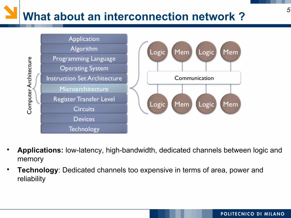
What about an interconnection network ?
Applications: low-latency, high-bandwidth, dedicated channels between logic and memory
Technology: Dedicated channels too expensive in terms of area, power and reliability
5
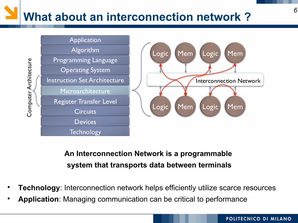
What about an interconnection network ?
An Interconnection Network is a programmable
system that transports data between terminals
Technology: Interconnection network helps efficiently utilize scarce resources Application: Managing communication can be critical to performance
6
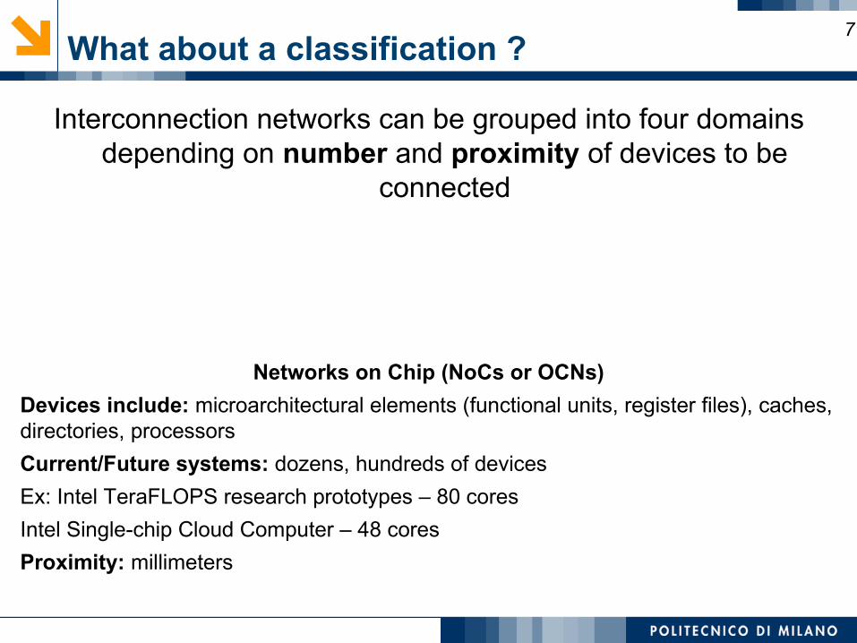
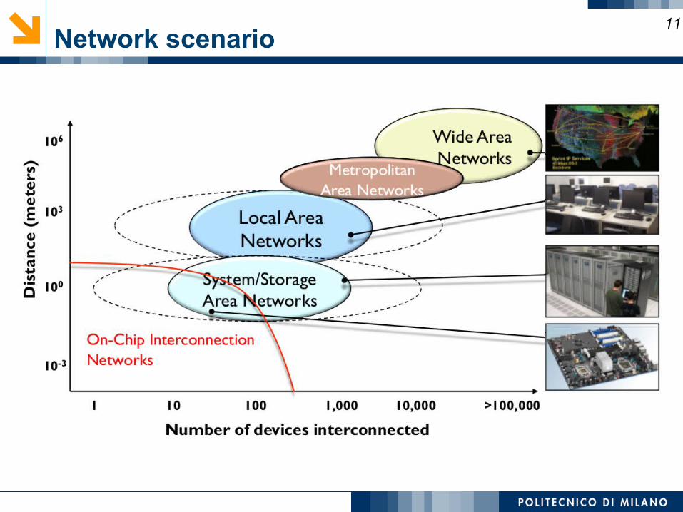
What about a classification ?
Interconnection networks can be grouped into four domains depending on number and proximity of devices to be
connected
Networks on Chip (NoCs or OCNs)
Devices include: microarchitectural elements (functional units, register files), caches, directories, processors
Current/Future systems: dozens, hundreds of devices
Ex: Intel TeraFLOPS research prototypes – 80 cores
Intel Single-chip Cloud Computer – 48 cores
Proximity: millimeters
7
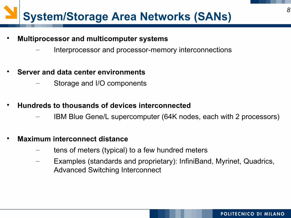
System/Storage Area Networks (SANs)
Multiprocessor and multicomputer systems
– Interprocessor and processor-memory interconnections
Server and data center environments
– Storage and I/O components
Hundreds to thousands of devices interconnected
– IBM Blue Gene/L supercomputer (64K nodes, each with 2 processors)
Maximum interconnect distance
– tens of meters (typical) to a few hundred meters
– Examples (standards and proprietary): InfiniBand, Myrinet, Quadrics, Advanced Switching Interconnect
8
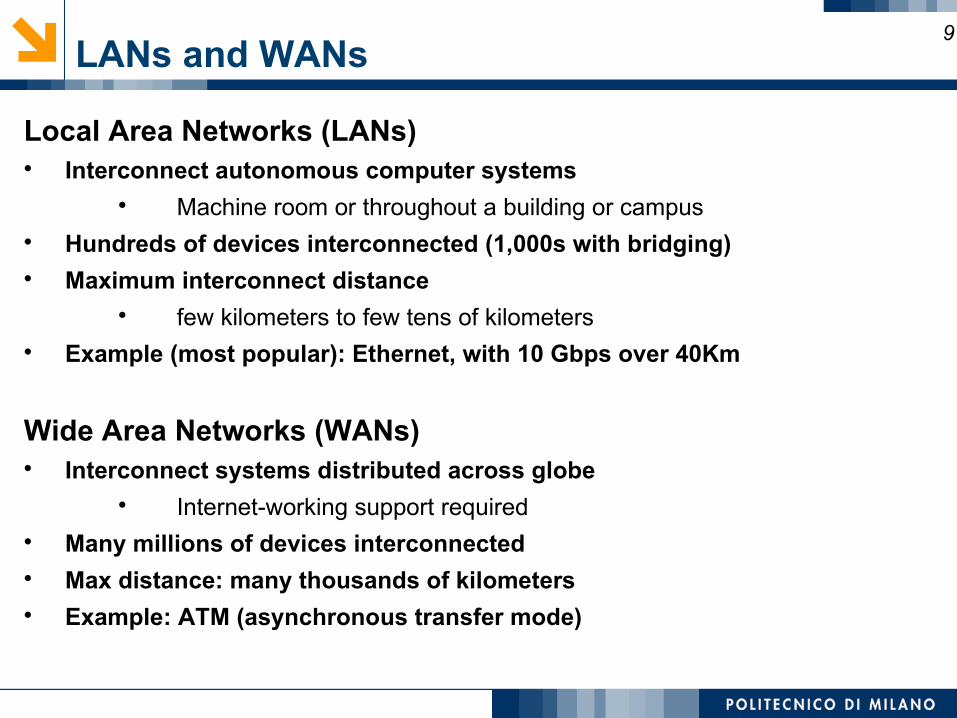
LANs and WANs
Local Area Networks (LANs) Interconnect autonomous computer systems
Machine room or throughout a building or campus Hundreds of devices interconnected (1,000s with bridging) Maximum interconnect distance
few kilometers to few tens of kilometers Example (most popular): Ethernet, with 10 Gbps over 40Km
Wide Area Networks (WANs) Interconnect systems distributed across globe
Internet-working support required Many millions of devices interconnected Max distance: many thousands of kilometers Example: ATM (asynchronous transfer mode)
9
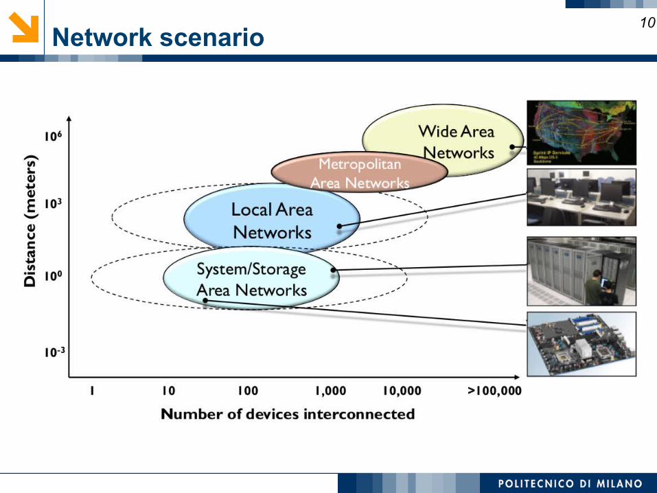
Network scenario10
Network scenario11
Why networks ?12
What about computing demands ?13
The energy-performance wall14
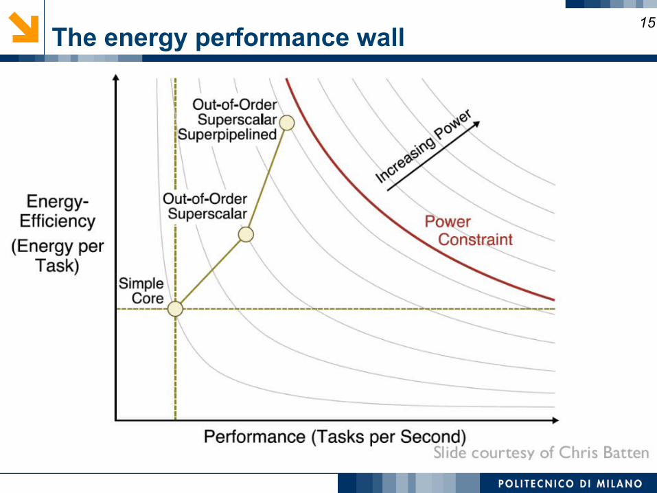
The energy performance wall15
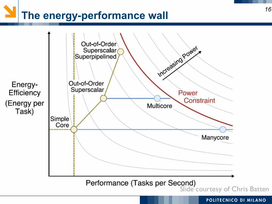
The energy-performance wall16
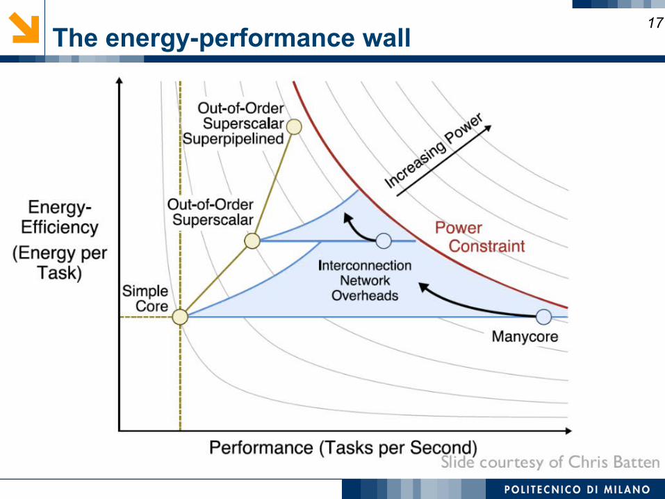
The energy-performance wall17
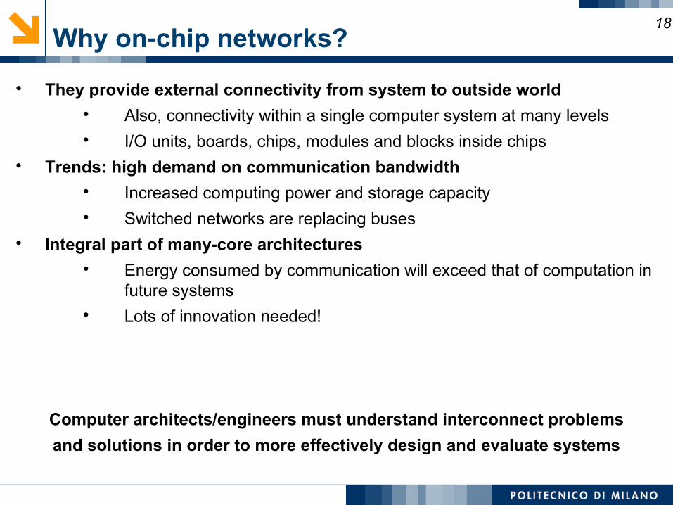
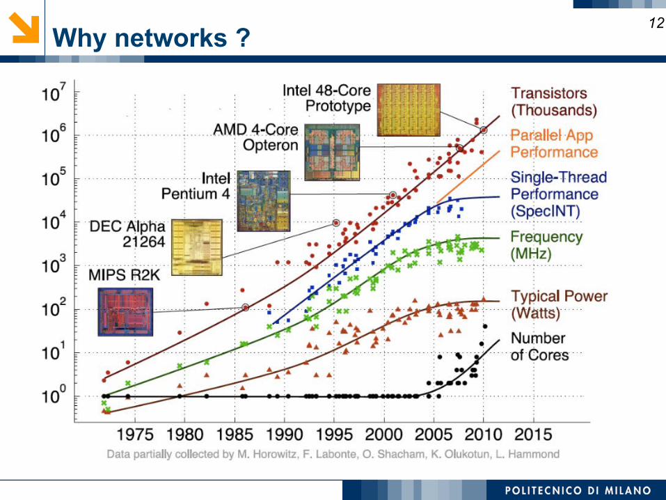
Why on-chip networks?
They provide external connectivity from system to outside world Also, connectivity within a single computer system at many levels I/O units, boards, chips, modules and blocks inside chips
Trends: high demand on communication bandwidth Increased computing power and storage capacity Switched networks are replacing buses
Integral part of many-core architectures Energy consumed by communication will exceed that of computation in
future systems Lots of innovation needed!
Computer architects/engineers must understand interconnect problems
and solutions in order to more effectively design and evaluate systems
18
On-chip vs off-chip
Significant research in multi-chassis interconnection networks (off-chip) Supercomputers and Clusters of workstations Internet routers Leverage research and insight but...
Constraints are different Pin-limited bandwidth Mix of short and long packets on-chip Inherent overheads of off-chip I/O transmission
New research area to meet performance, area, thermal, power and reliability needs (On-chip)
Wiring constraints and metal layer limitations Horizontal and vertical layout Short, fixed length Repeater insertion limits routing of wires Avoid routing over dense logic Impact wiring density
19
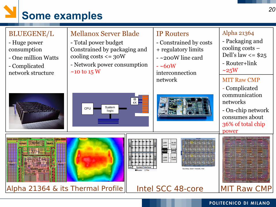
BLUEGENE/L- Huge power consumption
- One million Watts
- Complicated network structure
Mellanox Server Blade- Total power budget Constrained by packaging and cooling costs <= 30W
- Network power consumption ~10 to 15 W
IP Routers- Constrained by costs + regulatory limits
- ~200W line card
- ~60W interconnection network
Alpha 21364
- Packaging and cooling costs – Dell’s law <= $25
- Router+link ~25W
MIT Raw CMP
- Complicated communication networks
- On-chip network consumes about 36% of total chip power
Alpha 21364 & its Thermal Profile MIT Raw CMP
CPU Systemlogic
IB4X
Some examples
Intel SCC 48-core
20
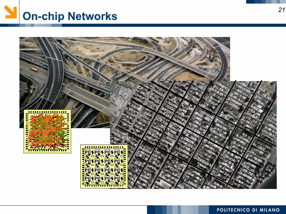
On-chip Networks21
PEPE PEPE
PEPE PEPE
PEPE PEPE
PEPE PEPE
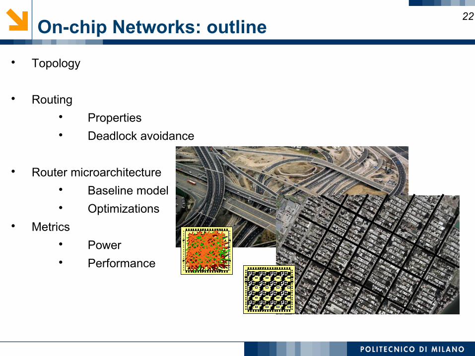
22On-chip Networks: outline
Topology
Routing Properties Deadlock avoidance
Router microarchitecture Baseline model Optimizations
Metrics Power Performance
PEPE PEPE
PEPE PEPE
PEPE PEPE
PEPE PEPE
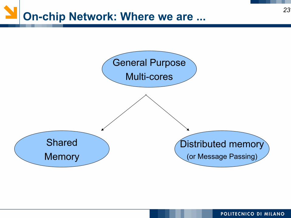
On-chip Network: Where we are ...23
General Purpose
Multi-cores
Distributed memory(or Message Passing)
Shared
Memory
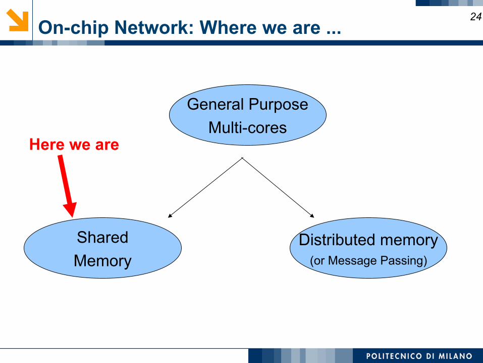
On-chip Network: Where we are ...24
General Purpose
Multi-cores
Distributed memory(or Message Passing)
Shared
Memory
Here we are
Shared memory multi-core
25
Memory Model in CMPs
Message Passing Explicit movement of data between nodes and address spaces Programmers manage communication
Shared Memory Communication occurs implicitly through loads/stores and accessing
instructions Will focus on shared memory Look at optimization for cache coherence protocols
26
Memory Model in CMPs
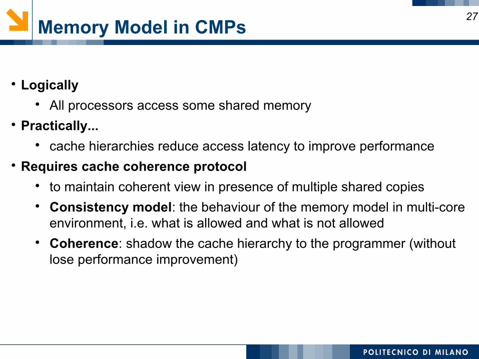
Logically All processors access some shared memory
Practically... cache hierarchies reduce access latency to improve performance
Requires cache coherence protocol to maintain coherent view in presence of multiple shared copies Consistency model: the behaviour of the memory model in multi-core
environment, i.e. what is allowed and what is not allowed Coherence: shadow the cache hierarchy to the programmer (without
lose performance improvement)
27
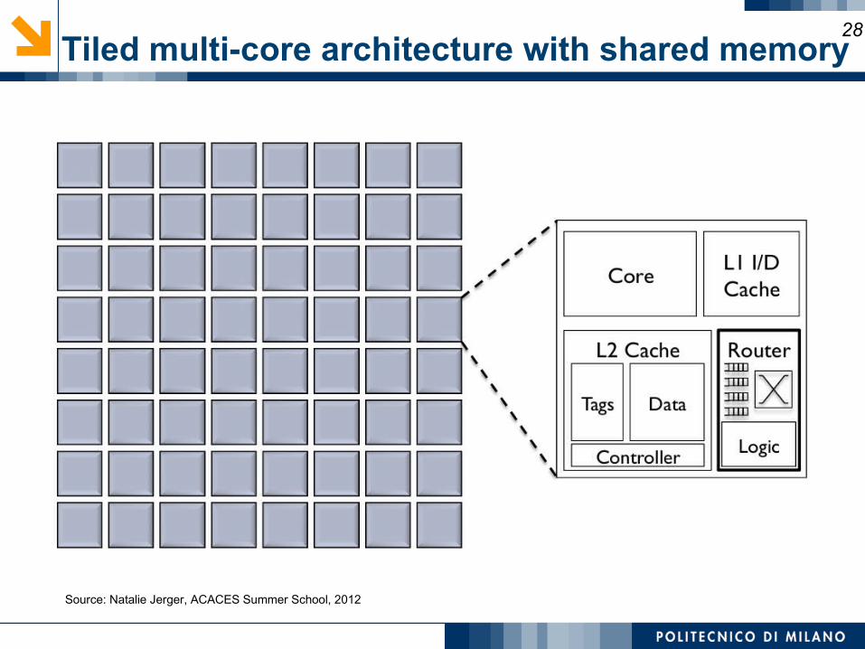
Tiled multi-core architecture with shared memory28
Source: Natalie Jerger, ACACES Summer School, 2012
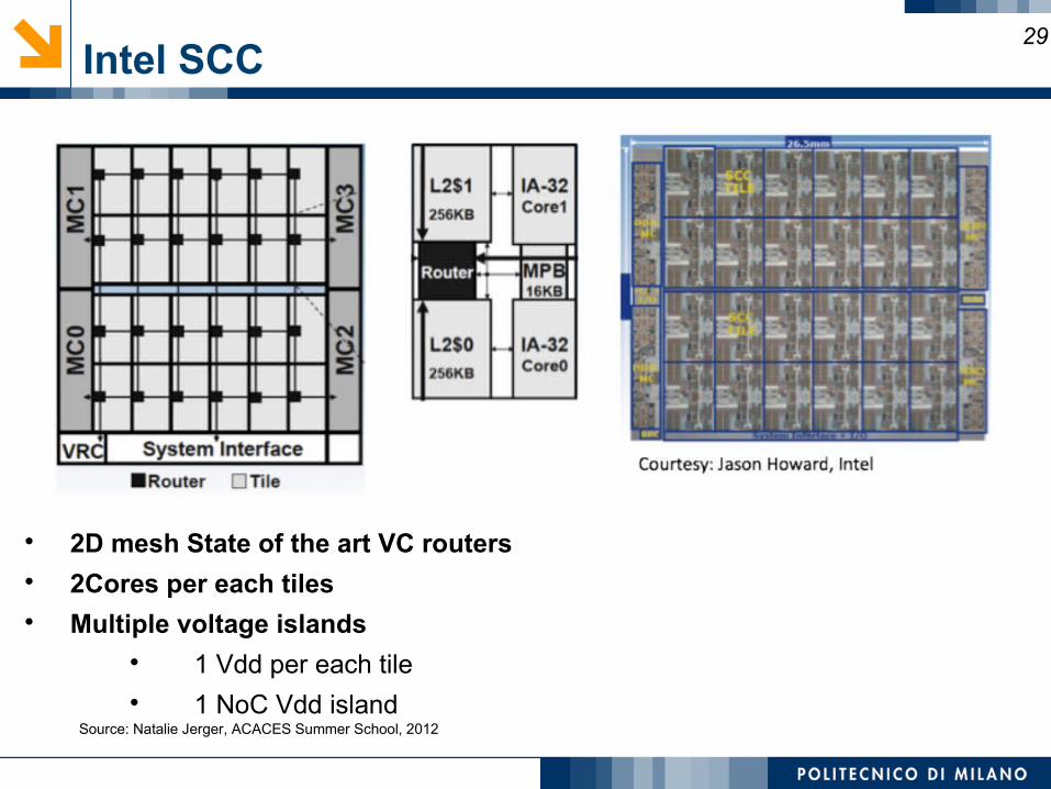
Intel SCC
2D mesh State of the art VC routers 2Cores per each tiles Multiple voltage islands
1 Vdd per each tile 1 NoC Vdd island
29
Source: Natalie Jerger, ACACES Summer School, 2012
Coherence Protocol on Network Performance30
Coherence protocol shapes communication needed by system
Single writer, multiple reader invariant Requires:
Data requests Data responses Coherence permissions
Suggested reading for a quick review of coherence:
“A Primer on Memory Consistency and Cache Coherence”, Daniel
Sorin, Mark Hill and David Wood. Morgan Claypool Publishers, 2011.
Hardware cache coherence31
Rough goal: all caches have same data at all times Minimal flushing, maximum caches → best performance
Two solutions: Broadcast-based protocol:
All processors see all requests at the same time, same order. Often relies on bus But can broadcast on unordered interconnect
Directory-based protocol: Order of the requests relies on a different mechanism than bus Maybe better flexibility and scalability Maybe higher latency
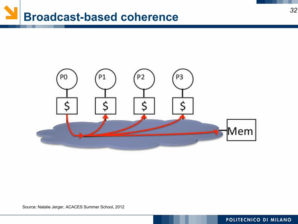
Broadcast-based coherence32
Source: Natalie Jerger, ACACES Summer School, 2012
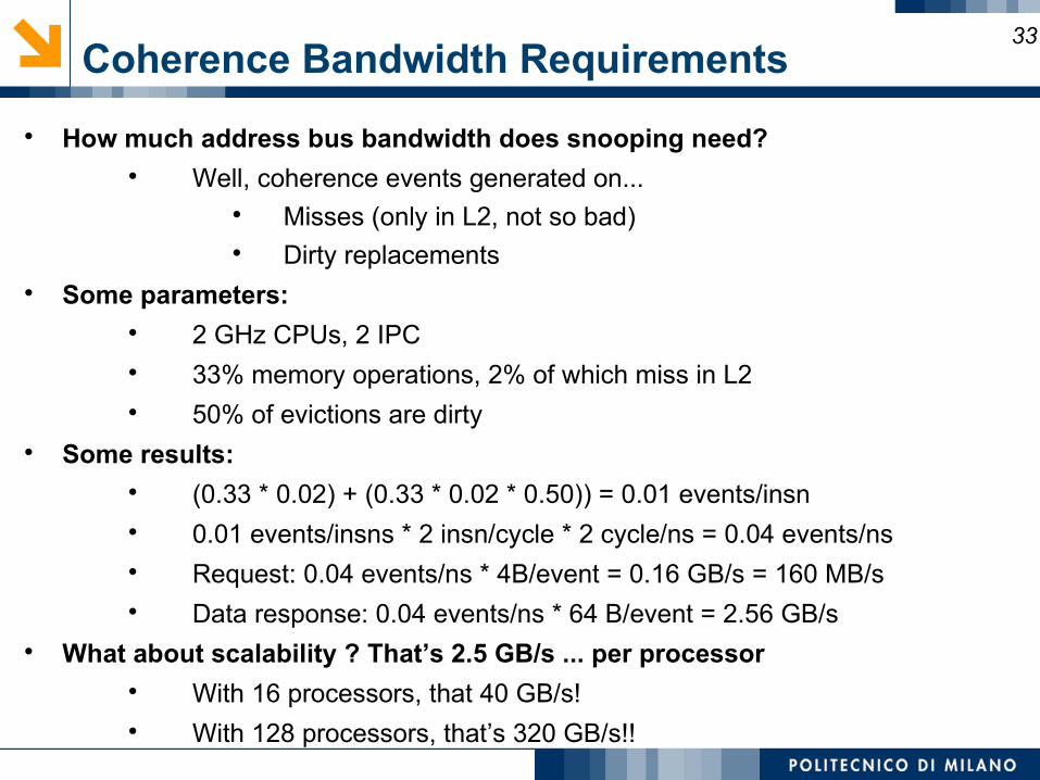
Coherence Bandwidth Requirements33
How much address bus bandwidth does snooping need? Well, coherence events generated on...
Misses (only in L2, not so bad) Dirty replacements
Some parameters: 2 GHz CPUs, 2 IPC 33% memory operations, 2% of which miss in L2 50% of evictions are dirty
Some results: (0.33 * 0.02) + (0.33 * 0.02 * 0.50)) = 0.01 events/insn 0.01 events/insns * 2 insn/cycle * 2 cycle/ns = 0.04 events/ns Request: 0.04 events/ns * 4B/event = 0.16 GB/s = 160 MB/s Data response: 0.04 events/ns * 64 B/event = 2.56 GB/s
What about scalability ? That’s 2.5 GB/s ... per processor With 16 processors, that 40 GB/s! With 128 processors, that’s 320 GB/s!!
Scalable Cache Coherence34
Two parts solution: Bus-based interconnect:
Replace non-scalable bandwidth substrate (bus)... ... with scalable bandwidth substrate (point-to-point network,
e.g. mesh) Processor'snooping'bandwidth:
Interesting most snoops result in no actions Replace non scalable broadcast protocol (it spam
everyone)...with scalable directory protocol (it only spams processors that care)
NOTE: physical address space statically partitioned (Still shared!!) Can easily determine which memory module holds a given line That memory module sometimes called “home” Can’t easily determine which processors have line in their caches Bus-based protocol: broadcast events to all processors/caches Simple and fast, but non-scalable
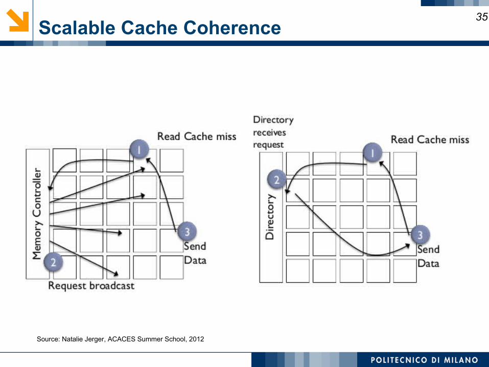
Scalable Cache Coherence35
Source: Natalie Jerger, ACACES Summer School, 2012
Coherence Protocol Requirements36
Different message types Unicast, multicast, broadcast
Directory protocol Majority of requests: Unicast Lower bandwidth demands on network More scalable due to point-to-point communication
Broadcast protocol Majority of requests: Broadcast Higher bandwidth demands Often rely on network ordering
Impact of Cache Hierarchy37
Sharing of injection/ejection port among cores and caches
Caches reduce average memory latency Private caches
Multiple L2 copies Data can be replicated to be close to processor
Shared caches Data can only exist in one L2 to bank Addresses striped across banks (Lots of different ways to do
this) Aside: lots of research on cache block placement, replication and
migration
Serve as filter for interconnect traffic
Private vs. Shared Caches38
Private caches Reduce latency of L2 cache hits keep frequently accessed data close to processor Increase off-chip pressure
Shared caches Better use of storage Non-uniform L2 hit latency More on-chip network pressure
all L1 misses go onto network
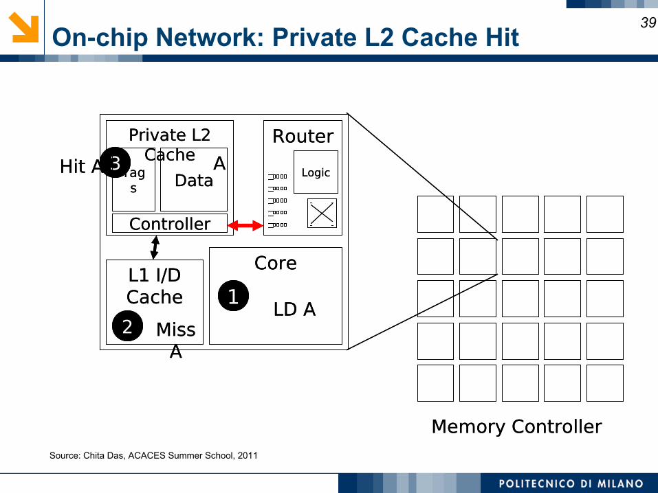
On-chip Network: Private L2 Cache Hit39
1
2LD A
3
Miss A
CoreL1 I/D Cache
Private L2 Cache
Router
Tags Data
Controller
LogicHit A
Memory Controller
A
1
2LD A
3
Miss A
CoreL1 I/D Cache
Private L2 Cache
Router
Tags Data
Controller
LogicHit A
Memory Controller
A
Source: Chita Das, ACACES Summer School, 2011
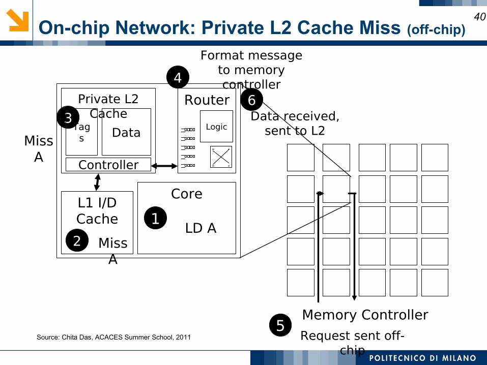
On-chip Network: Private L2 Cache Miss (off-chip)40
1
2LD A
3
Miss A
CoreL1 I/D Cache
Private L2 Cache
Router
Tags Data
Controller
Logic
Miss A
4
Format message to memory controller
Memory Controller5
6Data received,
sent to L2
Request sent off-chip
Source: Chita Das, ACACES Summer School, 2011
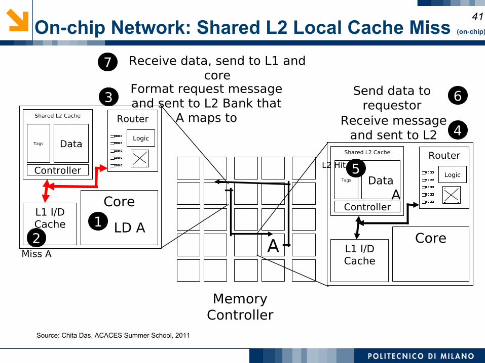
On-chip Network: Shared L2 Local Cache Miss (on-chip)
41
A
12
LD A
3
Miss A
Memory Controller
CoreL1 I/D Cache
Shared L2 Cache Router
Tags Data
Controller
Logic
CoreL1 I/D Cache
Shared L2 Cache Router
Tags Data
Controller
Logic
Format request message and sent to L2 Bank that
A maps to4
Receive message and sent to L2
5L2 Hit
6Send data to requestor
7 Receive data, send to L1 and core
A
Source: Chita Das, ACACES Summer School, 2011
Network-on-Chip details
42
Topology nomenclature 1
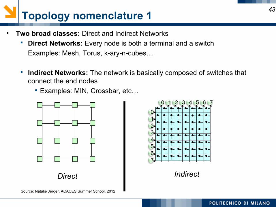
• Two broad classes: Direct and Indirect Networks Direct Networks: Every node is both a terminal and a switch
Examples: Mesh, Torus, k-ary-n-cubes…
Indirect Networks: The network is basically composed of switches that connect the end nodes
• Examples: MIN, Crossbar, etc…
43
Direct Indirect
Source: Natalie Jerger, ACACES Summer School, 2012
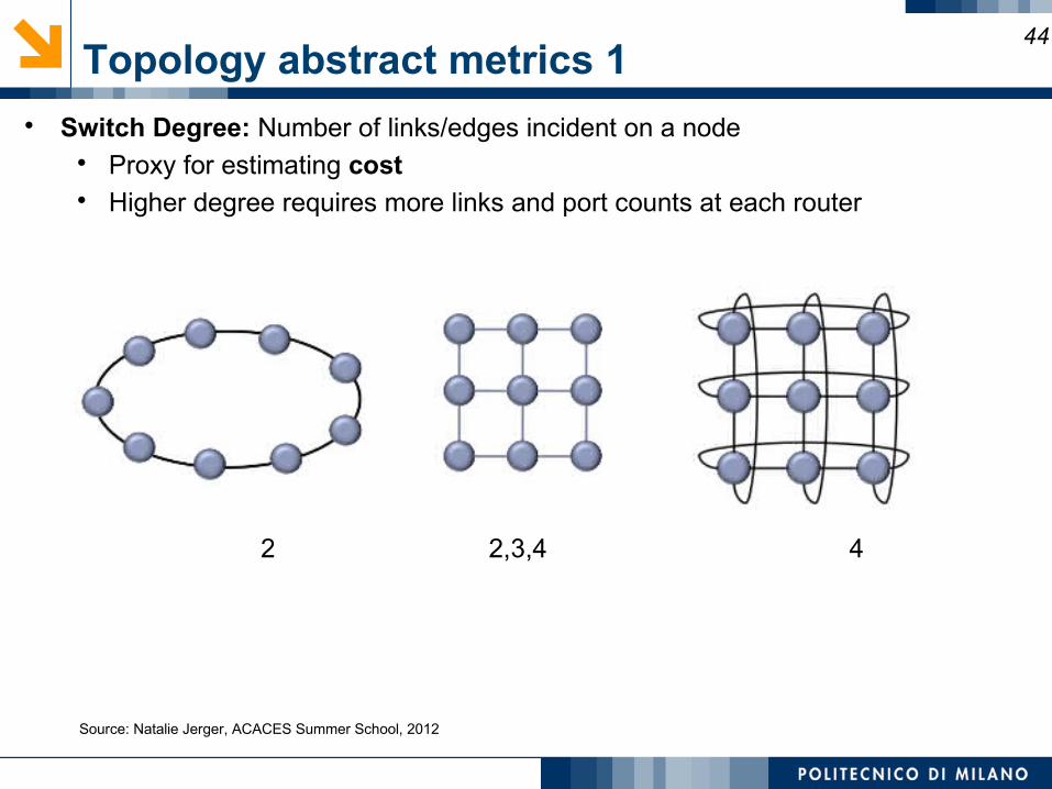
Topology abstract metrics 1 Switch Degree: Number of links/edges incident on a node
Proxy for estimating cost Higher degree requires more links and port counts at each router
44
2
2,3,4 4
Source: Natalie Jerger, ACACES Summer School, 2012
Topology abstract metrics 2
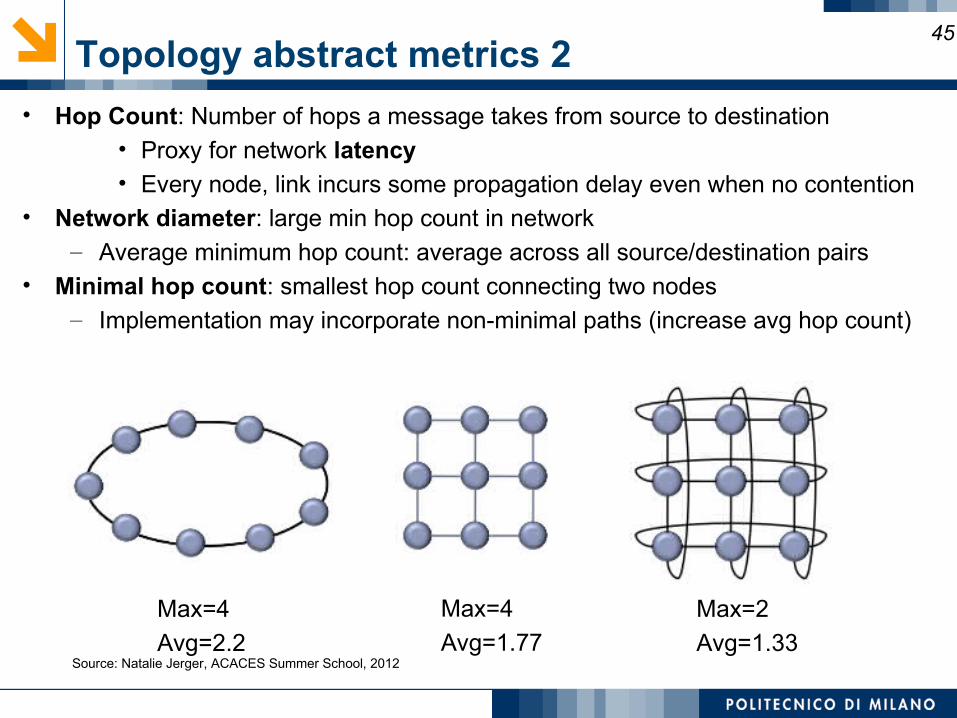
• Hop Count: Number of hops a message takes from source to destination• Proxy for network latency• Every node, link incurs some propagation delay even when no contention
• Network diameter: large min hop count in network– Average minimum hop count: average across all source/destination pairs
• Minimal hop count: smallest hop count connecting two nodes– Implementation may incorporate non-minimal paths (increase avg hop count)
45
Max=4
Avg=1.77
Max=4
Avg=2.2
Max=2
Avg=1.33 Source: Natalie Jerger, ACACES Summer School, 2012
Topology abstract metrics implications
• Abstract metrics are just proxies: Does not always correlate with the real metric they represent– Example:
• Network A with 2 hops, 5 stage pipeline, 4 cycle link traversal vs.• Network B with 3 hops, 1 stage pipeline, 1 cycle link traversal• Hop Count says A is better than B• But A has 18 cycle latency vs. 6 cycle latency for B
• Topologies typically trade-off hop count and node degree
46
Traffic patterns
• How to stress a NoC?– Synthetic traffic patterns
• Uniform random– Optimistic, it allows to view a bad network as a good one
• Matrix transpose• Many others based on probabilistic distributions and pattern selection
algorithms– Real traffic patterns
• Real benchmarks executed on the simulated architecture• More accurate• Complete evaluation of the system performance• Time consuming simulation
Is the selected traffic suitable for my application?
47
Routing, Arbitration, and Switching
Routing Defines the “allowed” path(s) for each packet (Which paths?) Problems
• Livelock and Deadlock
Arbitration Determines use of paths supplied to packets (When allocated?) Problems
Starvation
Switching Establishes the connection of paths for packets (How allocated?) Switching techniques
Circuit switching, Packet switching
48
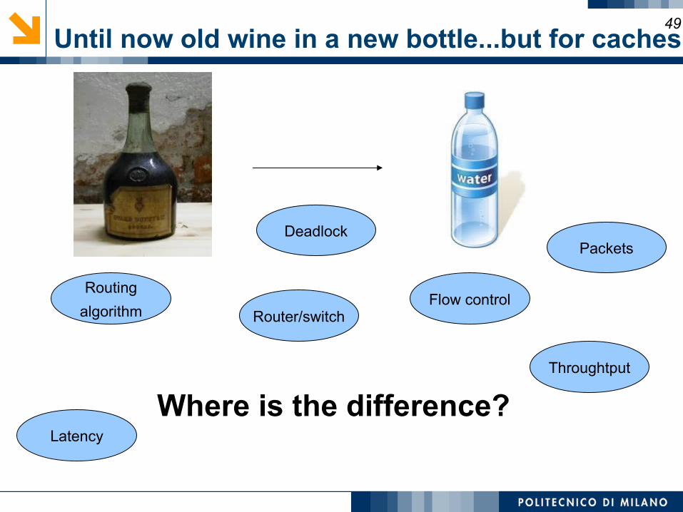
Until now old wine in a new bottle...but for caches49
Where is the difference?
Router/switch
Routing
algorithm
Packets
Flow control
Deadlock
Throughtput
Latency
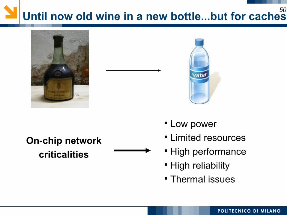
50
Low power Limited resources High performance High reliability Thermal issues
On-chip network
criticalities
Until now old wine in a new bottle...but for caches
NoC granulatity overview51
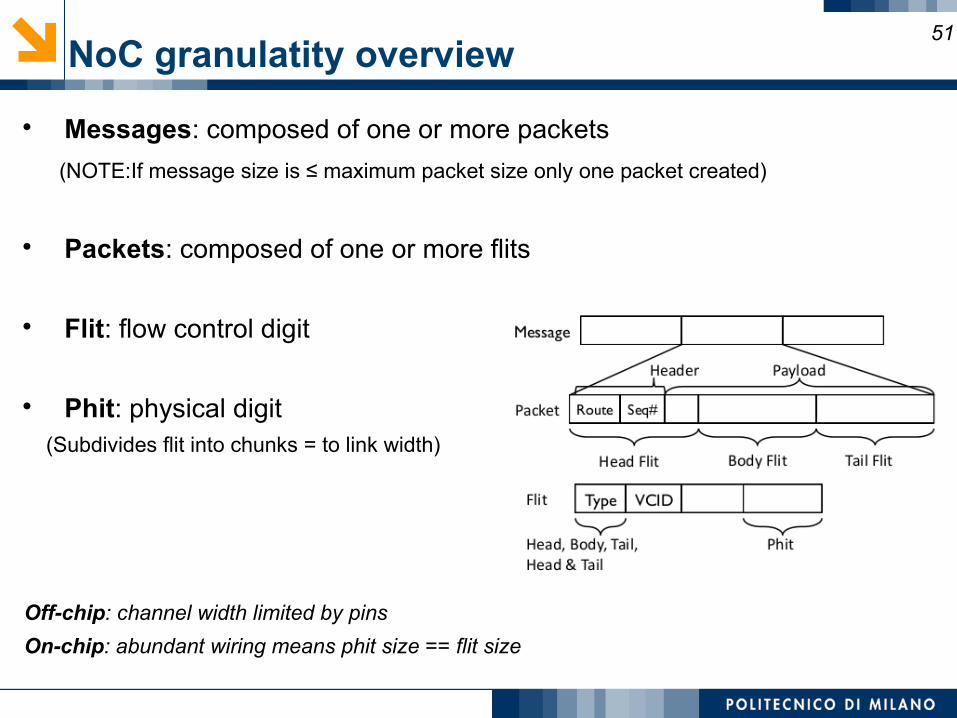
Messages: composed of one or more packets
(NOTE:If message size is ≤ maximum packet size only one packet created)
Packets: composed of one or more flits
Flit: flow control digit
Phit: physical digit (Subdivides flit into chunks = to link width)
Off-chip: channel width limited by pins
On-chip: abundant wiring means phit size == flit size
Routing overview52
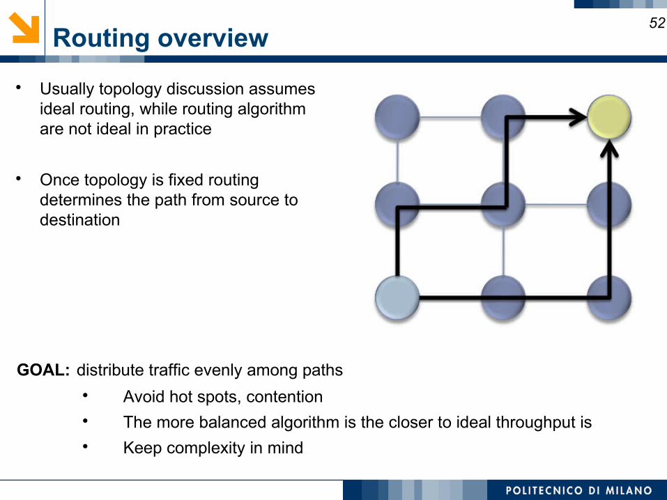
Usually topology discussion assumes ideal routing, while routing algorithm are not ideal in practice
Once topology is fixed routing determines the path from source to destination
GOAL: distribute traffic evenly among paths Avoid hot spots, contention The more balanced algorithm is the closer to ideal throughput is Keep complexity in mind
Routing algorithm attributes53
Types Deterministic: all the packets from each couple (source,destination)
uses always the same path regardless the network state Oblivious: random without adaptiveness routing, that is very efficiently
implementable Adaptive: the algorithm uses the network state to modify the routing
path for each packet even under the same source,destination pair
Routing path Minimal: all packets uses the shortest path from source to destination Non-minimal: packets may be routed to a longer path depending for
example on network state
Number of destinations Unicast: typical and easy solution in NoC Multicast: useful with cache coherence messages Broadcast: typical in bus-based architectures
The deadlock avoidance property54
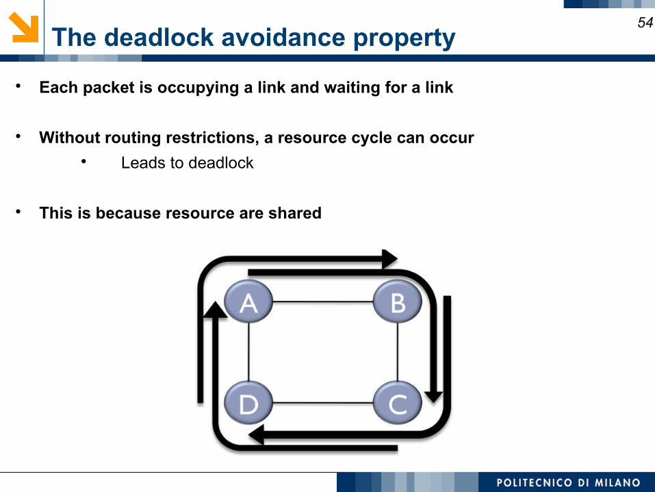
Each packet is occupying a link and waiting for a link
Without routing restrictions, a resource cycle can occur Leads to deadlock
This is because resource are shared
Deterministic routing55
All messages from Source to Destination traverse the same path
Common example: Dimension Order Routing (DOR) Message traverses network dimension by dimension Aka XY routing
Cons: Eliminates any path diversity provided by topology Poor load balancing
Pros: Simple and inexpensive to implement Deadlock-free (why???)
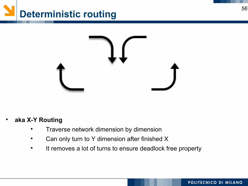
Deterministic routing56
aka X-Y Routing Traverse network dimension by dimension Can only turn to Y dimension after finished X It removes a lot of turns to ensure deadlock free property
Adaptive routing57
Exploits path diversity
Uses network state to make routing decisions Buffer occupancies often used Coupled with flow control mechanism
Local information readily available Global information more costly to obtain Network state can change rapidly Use of local information can lead to non-optimal choices
Can be minimal or non-minimal
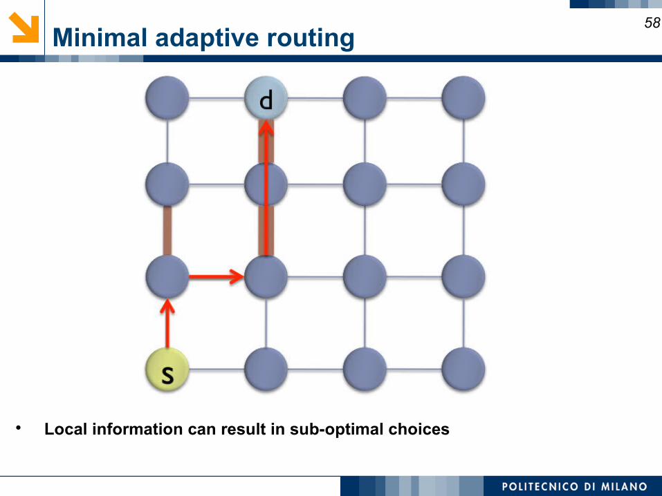
Minimal adaptive routing58
Local information can result in sub-optimal choices
Non-minimal adaptive routing59
Fully adaptive
Not restricted to take shortest path
Misrouting: directing packet along non-productive channel Priority given to productive output Some algorithms forbid U-turns
Livelock potential: traversing network without ever reaching destination Limit number of misroutings What about power consumption ?
Turn model for adaptive routing60
DOR eliminates 4 turns in a 2d-mesh topology with two cycles N to E, N to W, S to E, S to W No adaptivity
It is possible to do better? Hint: some models relax to eliminate 2 turns instead of 4 in 2d-mesh Turn model
Turn model for adaptive routing 161
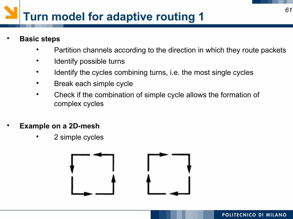
Basic steps Partition channels according to the direction in which they route packets Identify possible turns Identify the cycles combining turns, i.e. the most single cycles Break each simple cycle Check if the combination of simple cycle allows the formation of
complex cycles
Example on a 2D-mesh 2 simple cycles
Turn model for adaptive routing 262
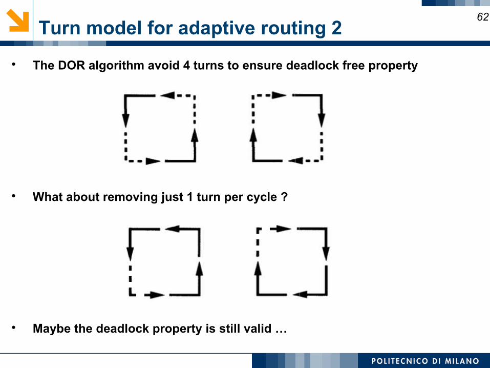
The DOR algorithm avoid 4 turns to ensure deadlock free property
What about removing just 1 turn per cycle ?
Maybe the deadlock property is still valid …
Turn model for adaptive routing 363
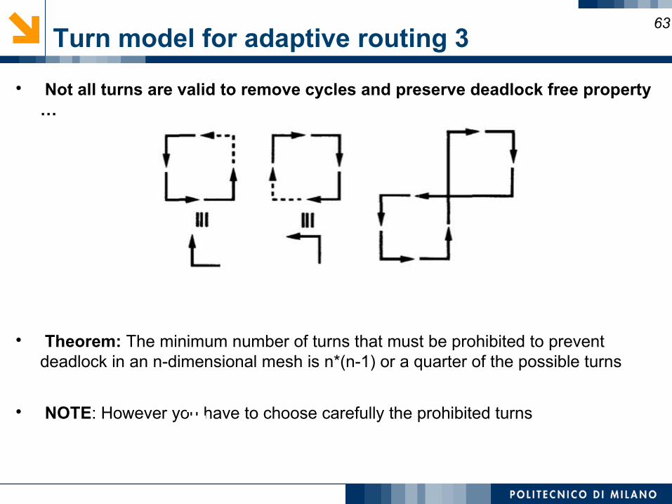
Not all turns are valid to remove cycles and preserve deadlock free property …
Theorem: The minimum number of turns that must be prohibited to prevent deadlock in an n-dimensional mesh is n*(n-1) or a quarter of the possible turns
NOTE: However you have to choose carefully the prohibited turns
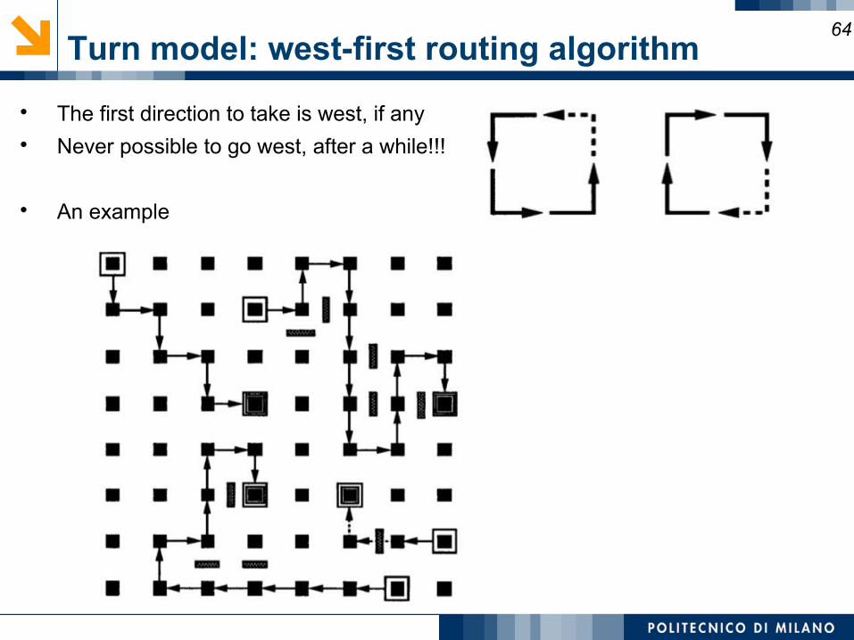
Turn model: west-first routing algorithm64
The first direction to take is west, if any Never possible to go west, after a while!!!
An example
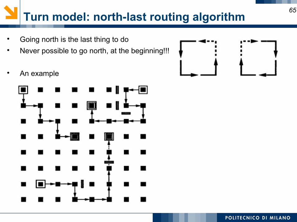
Turn model: north-last routing algorithm65
Going north is the last thing to do Never possible to go north, at the beginning!!!
An example
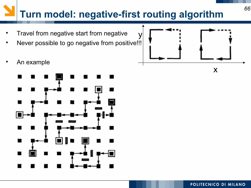
Turn model: negative-first routing algorithm66
Travel from negative start from negative Never possible to go negative from positive!!!
An examplex
y
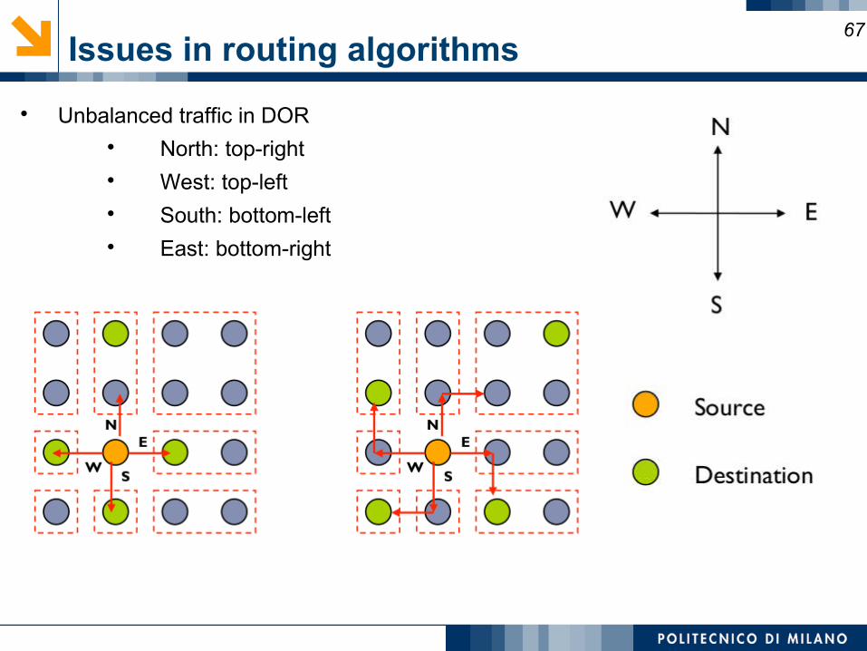
Issues in routing algorithms67
Unbalanced traffic in DOR North: top-right West: top-left South: bottom-left East: bottom-right
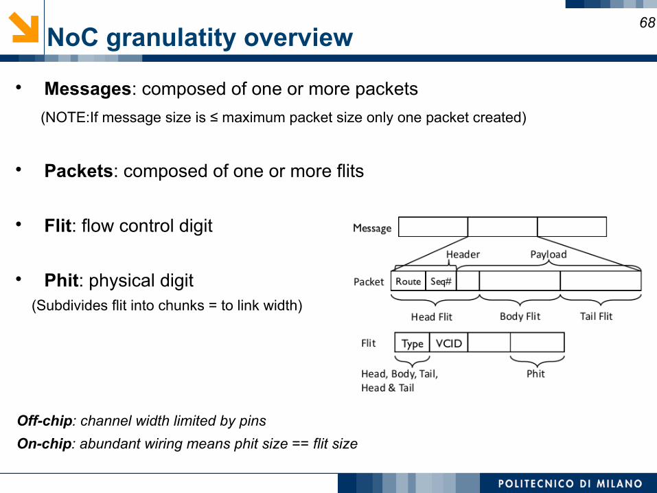
NoC granulatity overview68
Messages: composed of one or more packets
(NOTE:If message size is ≤ maximum packet size only one packet created)
Packets: composed of one or more flits
Flit: flow control digit
Phit: physical digit (Subdivides flit into chunks = to link width)
Off-chip: channel width limited by pins
On-chip: abundant wiring means phit size == flit size
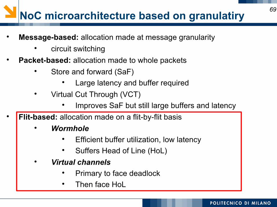
NoC microarchitecture based on granulatiry 69
Message-based: allocation made at message granularity circuit switching
Packet-based: allocation made to whole packets Store and forward (SaF)
Large latency and buffer required Virtual Cut Through (VCT)
Improves SaF but still large buffers and latency Flit-based: allocation made on a flit-by-flit basis
Wormhole Efficient buffer utilization, low latency Suffers Head of Line (HoL)
Virtual channels Primary to face deadlock Then face HoL
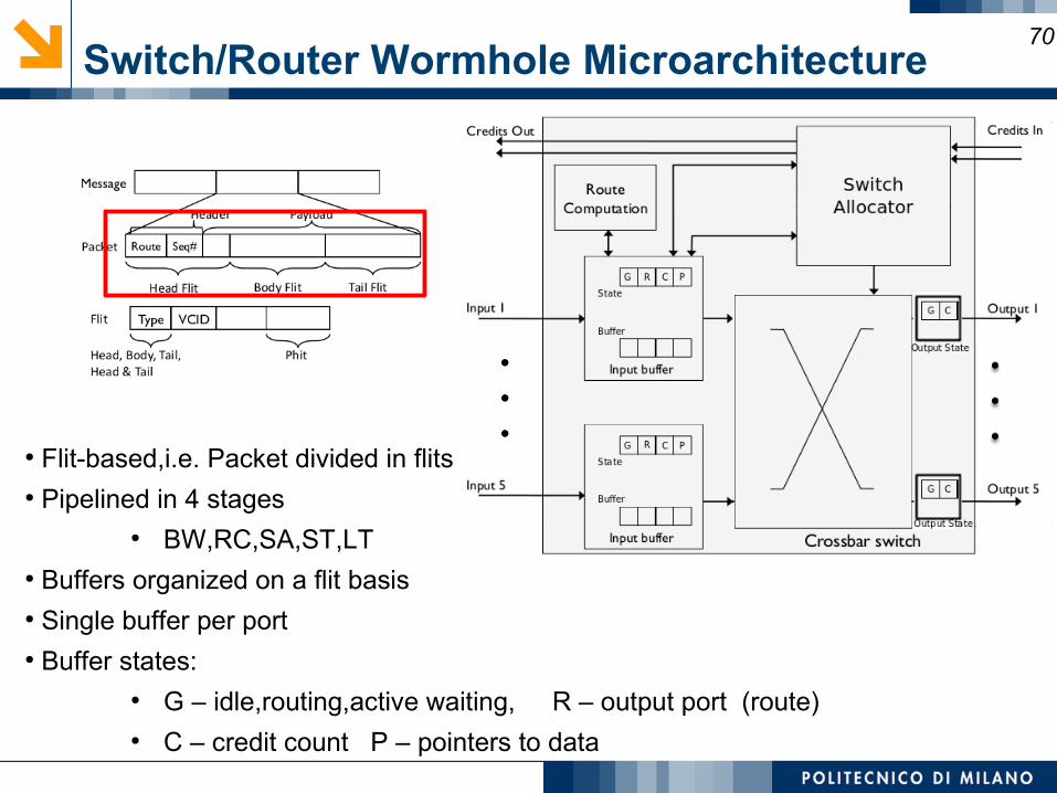
Switch/Router Wormhole Microarchitecture70
● Flit-based,i.e. Packet divided in flits● Pipelined in 4 stages
● BW,RC,SA,ST,LT● Buffers organized on a flit basis● Single buffer per port● Buffer states:
● G – idle,routing,active waiting, R – output port (route)● C – credit count P – pointers to data
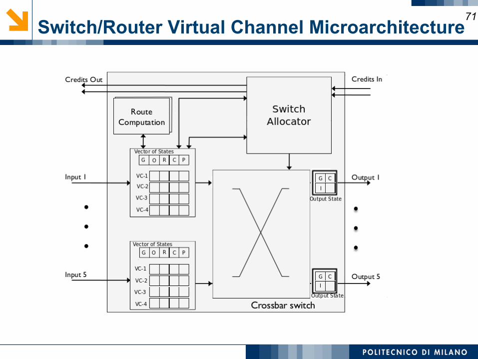
Switch/Router Virtual Channel Microarchitecture71
Router components72
Router components Input buffers, route computation logic, virtual channel allocator, switch allocator,
crossbar switch Most OCN routers are input buffered Use single-ported memories Buffer store flits for duration in router Contrast with processor pipeline that latches between stages
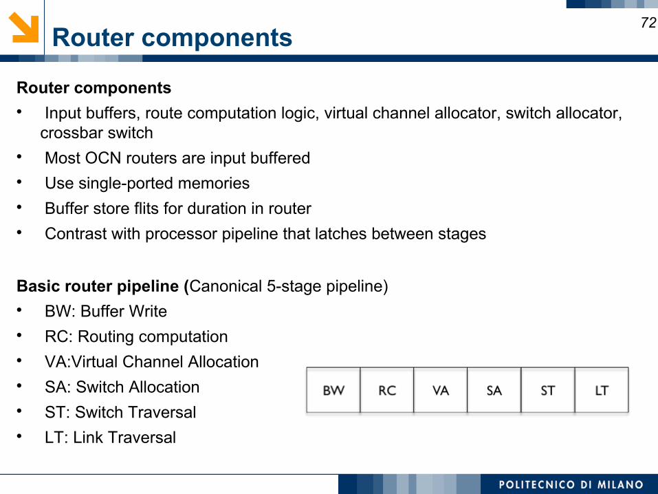
Basic router pipeline (Canonical 5-stage pipeline) BW: Buffer Write RC: Routing computation VA:Virtual Channel Allocation SA: Switch Allocation ST: Switch Traversal LT: Link Traversal
Router components73
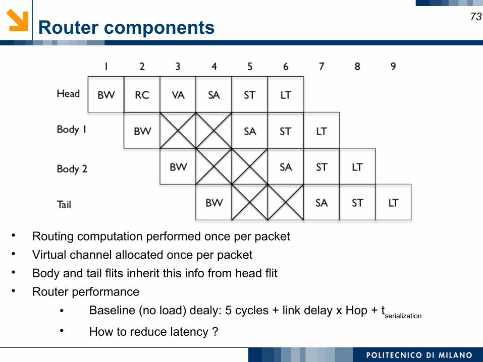
Routing computation performed once per packet Virtual channel allocated once per packet Body and tail flits inherit this info from head flit Router performance
Baseline (no load) dealy: 5 cycles + link delay x Hop + tserialization
How to reduce latency ?
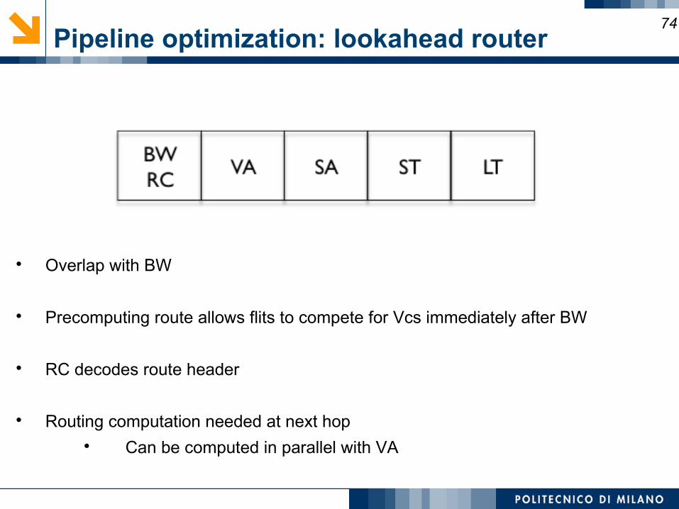
Pipeline optimization: lookahead router74
Overlap with BW
Precomputing route allows flits to compete for Vcs immediately after BW
RC decodes route header
Routing computation needed at next hop Can be computed in parallel with VA
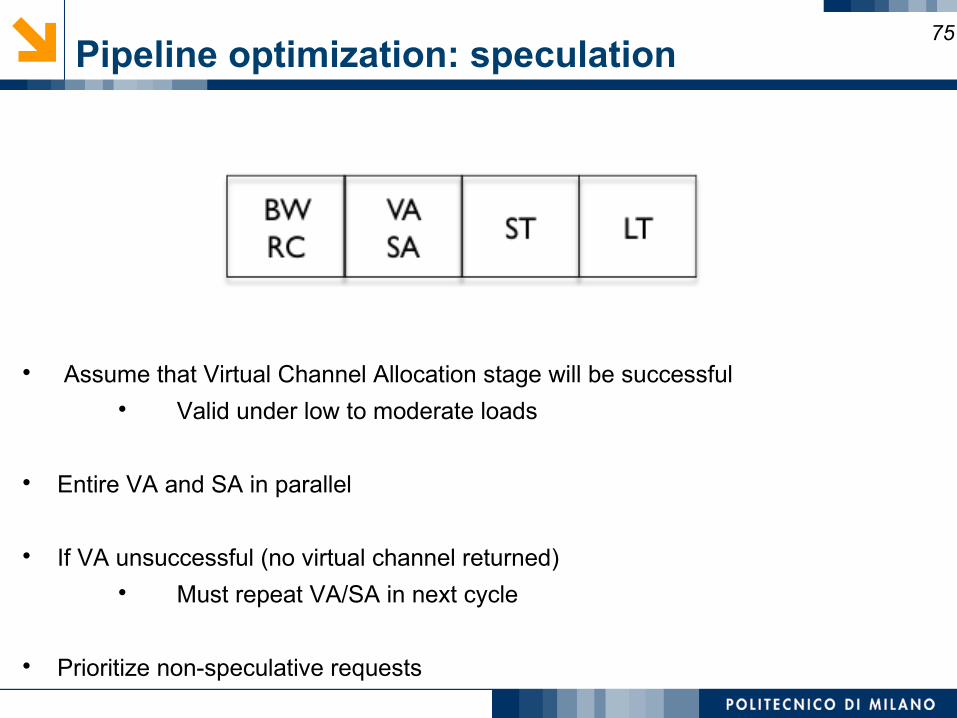
Pipeline optimization: speculation75
Assume that Virtual Channel Allocation stage will be successful Valid under low to moderate loads
Entire VA and SA in parallel
If VA unsuccessful (no virtual channel returned) Must repeat VA/SA in next cycle
Prioritize non-speculative requests
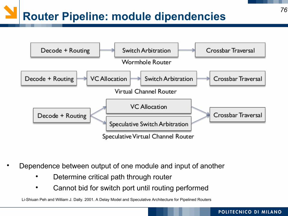
Router Pipeline: module dipendencies76
Dependence between output of one module and input of another Determine critical path through router Cannot bid for switch port until routing performed
Li-Shiuan Peh and William J. Dally. 2001. A Delay Model and Speculative Architecture for Pipelined Routers
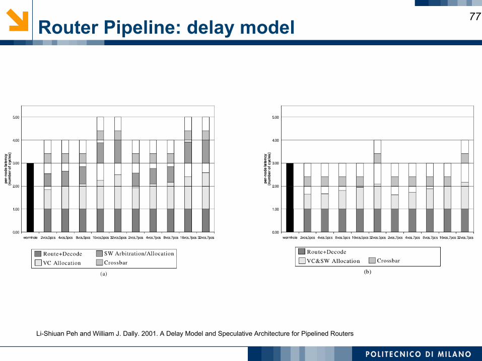
Router Pipeline: delay model77
Li-Shiuan Peh and William J. Dally. 2001. A Delay Model and Speculative Architecture for Pipelined Routers
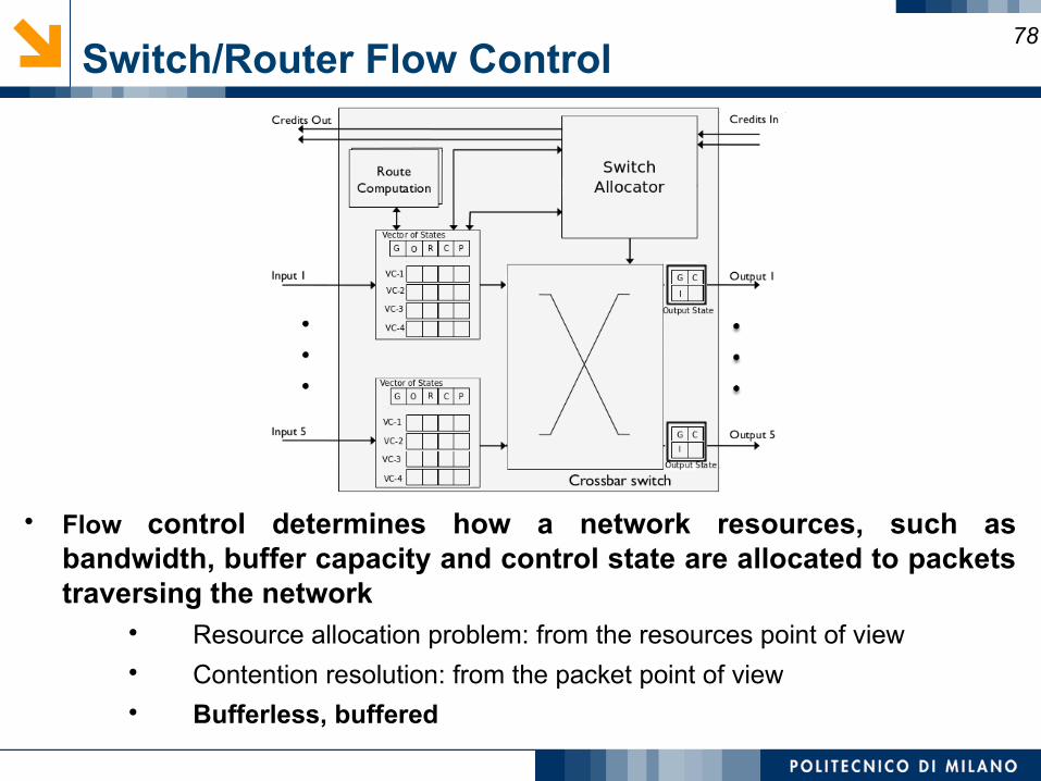
Switch/Router Flow Control78
Flow control determines how a network resources, such as bandwidth, buffer capacity and control state are allocated to packets traversing the network
Resource allocation problem: from the resources point of view Contention resolution: from the packet point of view Bufferless, buffered
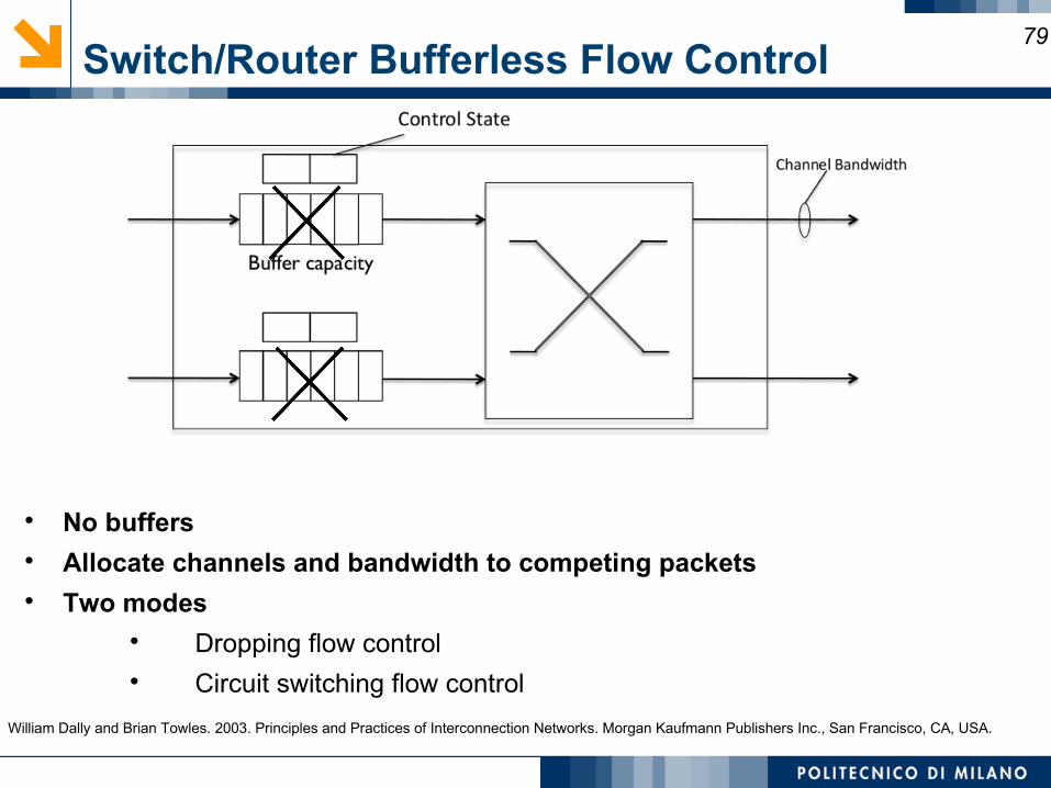
Switch/Router Bufferless Flow Control79
No buffers Allocate channels and bandwidth to competing packets Two modes
Dropping flow control Circuit switching flow control
William Dally and Brian Towles. 2003. Principles and Practices of Interconnection Networks. Morgan Kaufmann Publishers Inc., San Francisco, CA, USA.
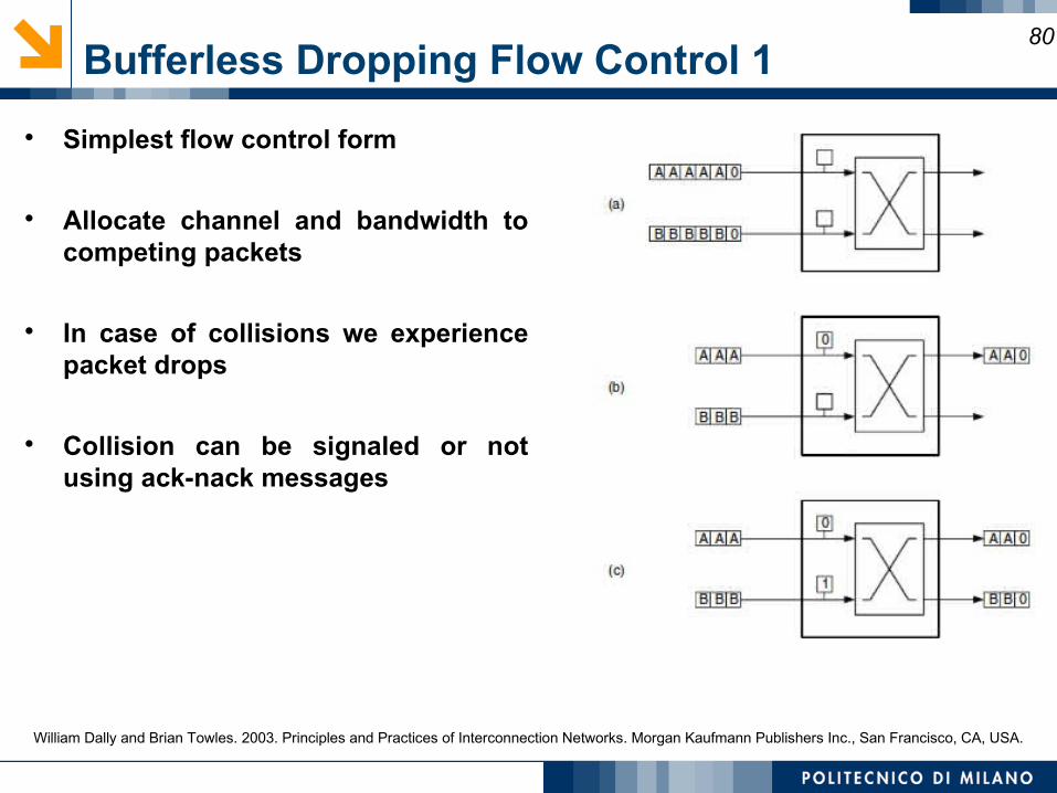
Bufferless Dropping Flow Control 180
Simplest flow control form
Allocate channel and bandwidth to competing packets
In case of collisions we experience packet drops
Collision can be signaled or not using ack-nack messages
William Dally and Brian Towles. 2003. Principles and Practices of Interconnection Networks. Morgan Kaufmann Publishers Inc., San Francisco, CA, USA.
Bufferless Dropping Flow Control 281
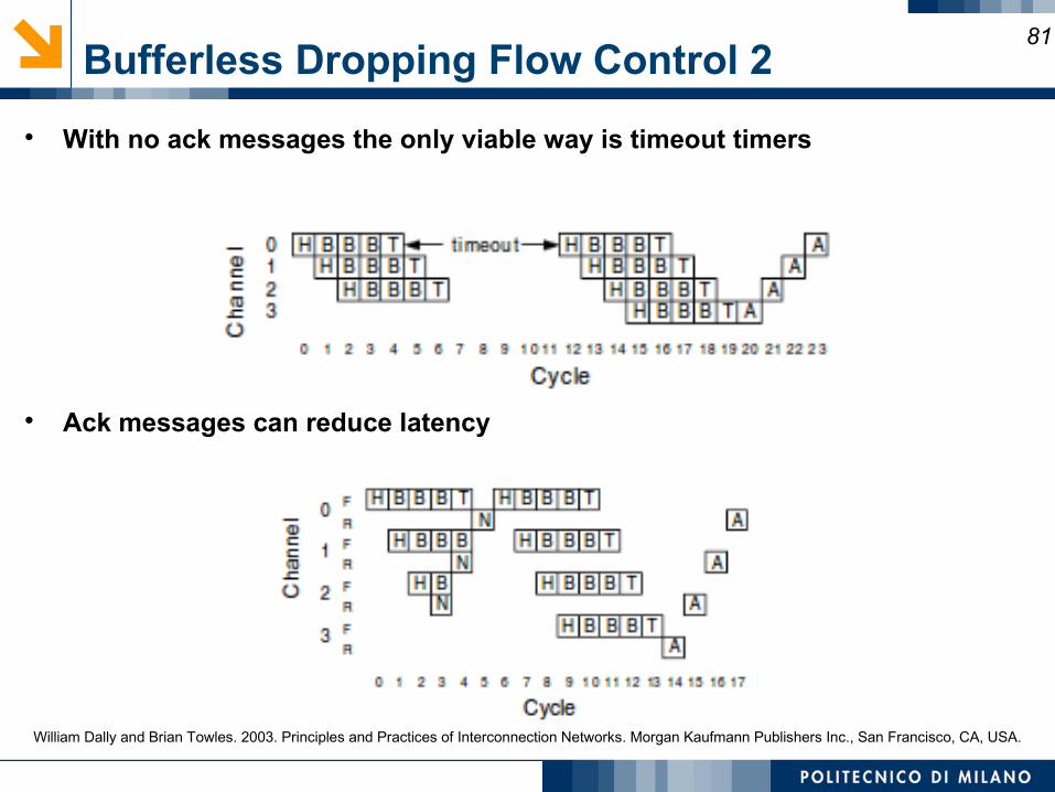
With no ack messages the only viable way is timeout timers
Ack messages can reduce latency
William Dally and Brian Towles. 2003. Principles and Practices of Interconnection Networks. Morgan Kaufmann Publishers Inc., San Francisco, CA, USA.
Bufferless Circuit switching Flow Control 182
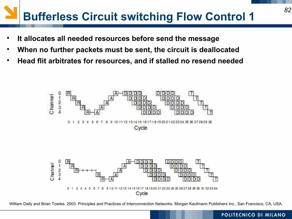
It allocates all needed resources before send the message When no further packets must be sent, the circuit is deallocated Head flit arbitrates for resources, and if stalled no resend needed
William Dally and Brian Towles. 2003. Principles and Practices of Interconnection Networks. Morgan Kaufmann Publishers Inc., San Francisco, CA, USA.
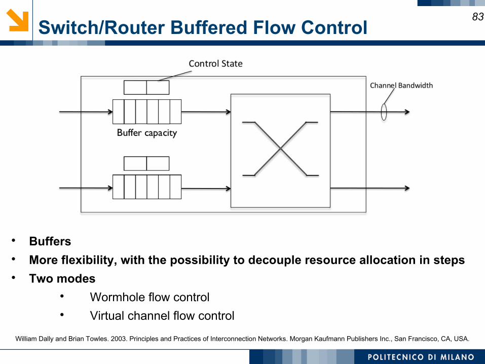
Switch/Router Buffered Flow Control83
Buffers More flexibility, with the possibility to decouple resource allocation in steps Two modes
Wormhole flow control Virtual channel flow control
William Dally and Brian Towles. 2003. Principles and Practices of Interconnection Networks. Morgan Kaufmann Publishers Inc., San Francisco, CA, USA.
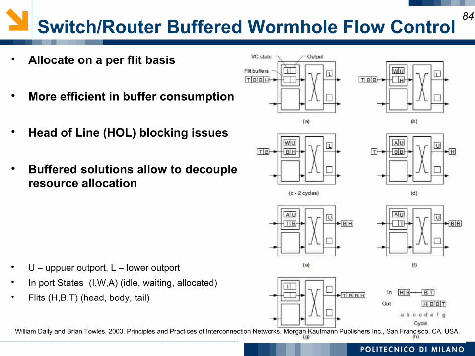
Switch/Router Buffered Wormhole Flow Control84
Allocate on a per flit basis
More efficient in buffer consumption
Head of Line (HOL) blocking issues
Buffered solutions allow to decouple resource allocation
U – uppuer outport, L – lower outport In port States (I,W,A) (idle, waiting, allocated) Flits (H,B,T) (head, body, tail)
William Dally and Brian Towles. 2003. Principles and Practices of Interconnection Networks. Morgan Kaufmann Publishers Inc., San Francisco, CA, USA.
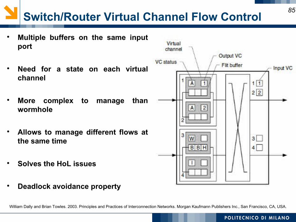
Switch/Router Virtual Channel Flow Control85
Multiple buffers on the same input port
Need for a state on each virtual channel
More complex to manage than wormhole
Allows to manage different flows at the same time
Solves the HoL issues
Deadlock avoidance property
William Dally and Brian Towles. 2003. Principles and Practices of Interconnection Networks. Morgan Kaufmann Publishers Inc., San Francisco, CA, USA.
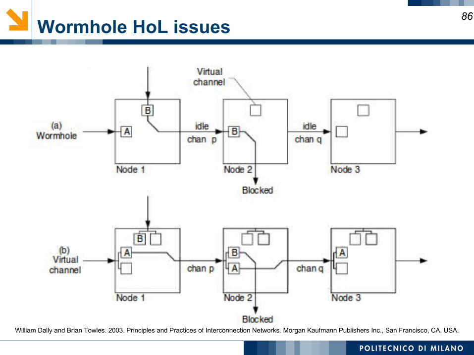
Wormhole HoL issues86
William Dally and Brian Towles. 2003. Principles and Practices of Interconnection Networks. Morgan Kaufmann Publishers Inc., San Francisco, CA, USA.
Buffer Management and Backpressure87
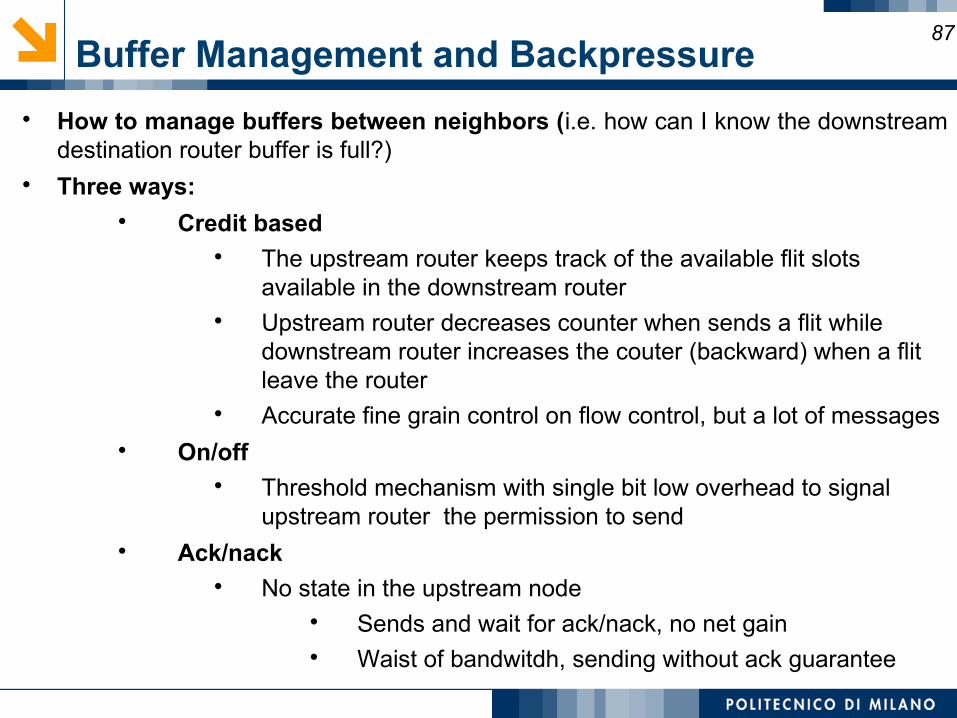
How to manage buffers between neighbors (i.e. how can I know the downstream destination router buffer is full?)
Three ways: Credit based
The upstream router keeps track of the available flit slots available in the downstream router
Upstream router decreases counter when sends a flit while downstream router increases the couter (backward) when a flit leave the router
Accurate fine grain control on flow control, but a lot of messages On/off
Threshold mechanism with single bit low overhead to signal upstream router the permission to send
Ack/nack No state in the upstream node
Sends and wait for ack/nack, no net gain Waist of bandwitdh, sending without ack guarantee
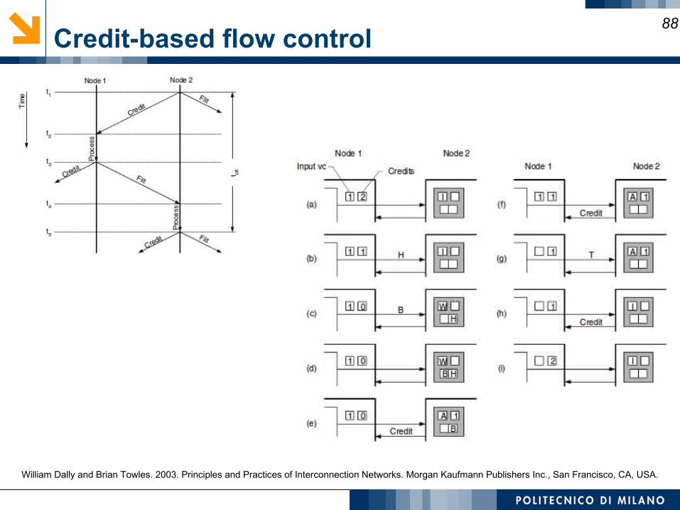
Credit-based flow control88
William Dally and Brian Towles. 2003. Principles and Practices of Interconnection Networks. Morgan Kaufmann Publishers Inc., San Francisco, CA, USA.
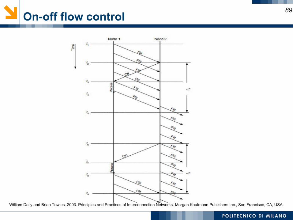
On-off flow control89
William Dally and Brian Towles. 2003. Principles and Practices of Interconnection Networks. Morgan Kaufmann Publishers Inc., San Francisco, CA, USA.
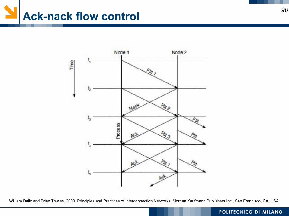
Ack-nack flow control90
William Dally and Brian Towles. 2003. Principles and Practices of Interconnection Networks. Morgan Kaufmann Publishers Inc., San Francisco, CA, USA.
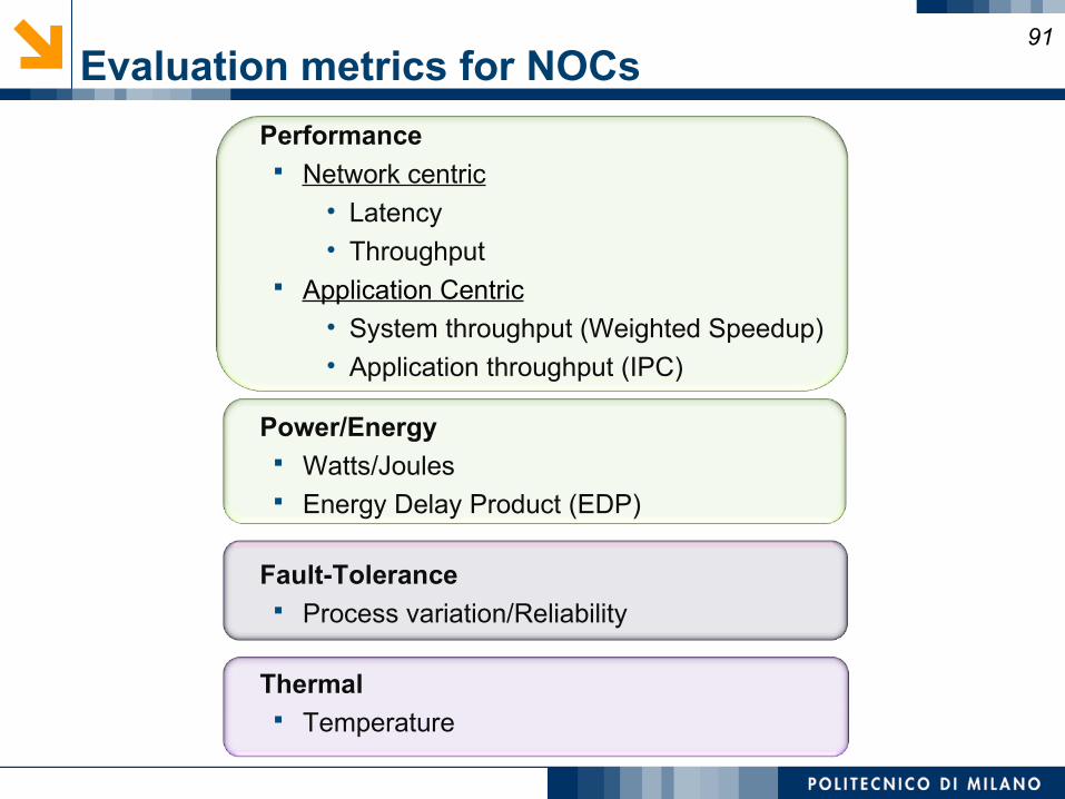
Evaluation metrics for NOCs
Performance Network centric
• Latency• Throughput
Application Centric• System throughput (Weighted Speedup)• Application throughput (IPC)
Power/Energy Watts/Joules Energy Delay Product (EDP)
Fault-Tolerance Process variation/Reliability
Thermal Temperature
91
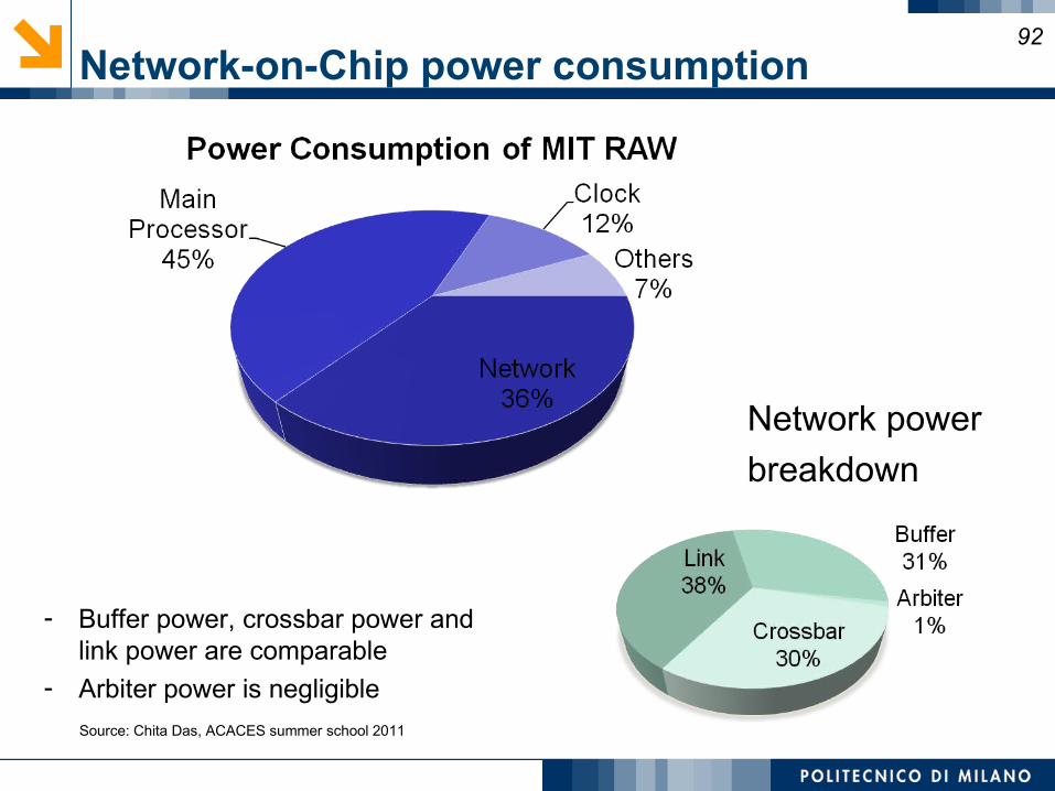
- Buffer power, crossbar power and link power are comparable
- Arbiter power is negligible
92
Network-on-Chip power consumption
Network power
breakdown
Source: Chita Das, ACACES summer school 2011
93Bibliography 2
Dally, W. J., and B. Towles [2004]. Principles and Practices of Interconnection Networks, Morgan Kaufmann Publishers, San Francisco.
C.A. Nicopoulos, N. Vijaykrishnan, and C.R. Das, “Network-on-Chip Architectures: A Holistic Design Exploration,” Lecture Notes in Electrical Engineering Book Series, Springer, October 2009.
G. De Micheli, L. Benini, ‘Networks on Chips: Technology and Tools,’ Morgan Kaufmann, 2006. J. Duato, S. Yalamanchili, and L. Ni, Interconnection Networks: An Engineering Approach,
Morgan Kaufmann, 2002. R. Marculescu, U. Y. Ogras, L.-S. Peh, N. E. Jerger, Y. Hoskote, 'Outstanding Research Problems in
NoC Design: System, Microarchitecture, and Circuit Perspectives', IEEE Trans. on Computer-Aided Design of Integrated Circuits and Systems (TCAD), vol. 28, pp. 3-21, Jan. 2009.
T. Bjerregaard and S. Mahadevan, “A survey of research and practices of network-onchip,” ACM Comput. Surv., vol. 38, no. 1, pp. 1–51, Mar. 2006.
Natalie Enright-Jerger and Li-Shiuan Peh, "On-Chip Networks", Synthesis Lecture, Morgan-Claypool Publishers, Aug. 2009
Agarwal, A. [1991]. “Limits on interconnection network performance,” IEEE Trans. on Parallel and Distributed Systems 2:4 (April), 398–412.
Dally, W. J., and B. Towles [2001]. “Route packets, not wires: On-chip interconnection networks,” Proc. of the Design Automation Conference, Las Vegas (June).
Ho, R., K. W. Mai, and M. A. Horowitz [2001]. “The future of wires,” Proc. of the IEEE 89:4 (April). Hangsheng Wang, Xinping Zhu, Li-Shiuan Peh and Sharad Malik, "Orion: A Power-Performance
Simulator for Interconnection Networks" , In Proceedings of MICRO 35, Istanbul, November 2002. D. Brooks, R. Dick, R. Joseph, and L. Shang, "Power, thermal, and reliability modeling in
nanometer-scale microprocessors, " IEEE Micro , 2007.

Thank youAny questions?
94