an integrated tunable interferometer controlled by liquid
TRANSCRIPT

An integrated tunable interferometer controlled
by liquid diffusion in polydimethylsiloxane
Yun Zou,1,2
Zhenhua Shen,1,2
Xiang Chen,3 Ziyun Di,
4 and Xianfeng Chen
1,2,*
1Department of Physics, Shanghai Jiao Tong University, Shanghai 200240, China 2The State Key Laboratory of Advanced Optical Communication Systems and Networks, Shanghai Jiao Tong
University, Shanghai 200240, China 3Key Laboratory for Thin Film and Microfabrication of the Ministry of Education,
Research Institute of Micro/Nano Science and Technology, Shanghai Jiao Tong University, Shanghai 200240, China 4The institute for Quantum Science and Engineering and Department of Physics & Astronomy,
Texas A&m University, College Station, Texas 77843, USA *[email protected]
Abstract: We demonstrated an integrated tunable interferometer in
Polydimethylsiloxane (PDMS). In contrast to most on-chip interferometers
which require complex fabrication, our design is realized by conventional
soft lithography fabrication. The optical path difference occurs during
propagation across a fluid-fluid interface. The diffusion level of the two
miscible liquids which is controlled by liquid flow rates provides tunability.
Different ratio of two liquid flow rates result in the interference spectral
shift. Interference peak numbers are varied with flow rate ratio of two
liquids. Mutual diffusion between two liquids changes the profile of the
refractive index across the fluidic channel. The two arms structure of our
design provides convenience for sensing and detection in biology system.
This device not only offers the convenience for microfluidic networks but
also paves the way for sensing in chemical microreactors.
© 2012 Optical Society of America
OCIS codes: (230.3990) Micro-optical devices; (160.5470) Polymers; (130.3120) Integrated
optics devices.
References and links
1. D. Psaltis, S. R. Quake, and C. Yang, “Developing optofluidic technology through the fusion of microfluidics
and optics,” Nature 442(7101), 381–386 (2006).
2. C. Monat, P. Domachuk, and B. J. Eggleton, “Integrated optofluidics: A new river of light,” Nat. Photonics 1(2),
106–114 (2007).
3. N. T. Nguyen, “Micro-optofluidic Lenses: A review,” Biomicrofluidics 4(3), 031501 (2010).
4. Z. Li and D. Psaltis, “Optofluidic dye lasers,” Microfluid. Nanofluid. 4(1–2), 145–158 (2008).
5. D. B. Wolfe, D. V. Vezenov, B. T. Mayers, G. M. Whitesides, R. S. Conroy, and M. G. Prentiss, “Diffusion-
controlled optical elements for optofluidics,” Appl. Phys. Lett. 87(18), 181105 (2005).
6. J. G. Cuennet, A. E. Vasdekis, L. De Sio, and D. Psaltis, “Optofluidic modulator based on peristaltic nematogen
microflows,” Nat. Photonics 5(4), 234–238 (2011).
7. M. B. Christiansen, J. M. Lopacinska, M. H. Jakobsen, N. A. Mortensen, M. Dufva, and A. Kristensen, “Polymer
photonic crystal dye lasers as Optofluidic Cell Sensors,” Opt. Express 17(4), 2722–2730 (2009).
8. R. Shamai and U. Levy, “On chip tunable micro ring resonator actuated by electrowetting,” Opt. Express 17(2),
1116–1125 (2009).
9. P. Domachuk, I. C. M. Littler, M. Cronin-Golomb, and B. J. Eggleton, “Compact resonant integrated
microfluidic refractometer,” Appl. Phys. Lett. 88(9), 093513 (2006).
10. L. K. Chin, A. Q. Liu, Y. C. Soh, C. S. Lim, and C. L. Lin, “A reconfigurable optofluidic Michelson
interferometer using tunable droplet grating,” Lab Chip 10(8), 1072–1078 (2010).
11. A. Crespi, Y. Gu, B. Ngamsom, H. J. W. M. Hoekstra, C. Dongre, M. Pollnau, R. Ramponi, H. H. van den
Vlekkert, P. Watts, G. Cerullo, and R. Osellame, “Three-dimensional Mach-Zehnder interferometer in a
microfluidic chip for spatially-resolved label-free detection,” Lab Chip 10(9), 1167–1173 (2010).
12. M. I. Lapsley, I.-K. Chiang, Y. B. Zheng, X. Y. Ding, X. Mao, and T. J. Huang, “A single-layer, planar,
optofluidic Mach-Zehnder interferometer for label-free detection,” Lab Chip 11(10), 1795–1800 (2011).
13. L. K. Chin, A. Q. Liu, Y. C. Soh, C. S. Lim, and C. L. Lin, “A reconfigurable optofluidic Michelson
interferometer using tunable droplet grating,” Lab Chip 10(8), 1072–1078 (2010).
#169750 - $15.00 USD Received 4 Jun 2012; revised 23 Jul 2012; accepted 23 Jul 2012; published 2 Aug 2012(C) 2012 OSA 13 August 2012 / Vol. 20, No. 17 / OPTICS EXPRESS 18931
14. R. Bernini, G. Testa, L. Zeni, and P. M. Sarro, “Integrated optofluidic Mach–Zehnder interferometer based on
liquid core waveguides,” Appl. Phys. Lett. 93(1), 011106 (2008).
15. P. Dumais, C. L. Callender, J. P. Noad, and C. J. Ledderhof, “Integrated optical sensor using a liquid-core
waveguide in a Mach-Zehnder interferometer,” Opt. Express 16(22), 18164–18172 (2008).
16. G. Testa, Y. J. Huang, P. M. Sarro, L. Zeni, and R. Bernini, “High-visibility optofluidic Mach-Zehnder
interferometer,” Opt. Lett. 35(10), 1584–1586 (2010).
17. A. Ymeti, J. Greve, P. V. Lambeck, T. Wink, S. W. F. M. van Hövell, T. A. M. Beumer, R. R. Wijn, R. G.
Heideman, V. Subramaniam, and J. S. Kanger, “Fast, ultrasensitive virus detection using a Young interferometer
sensor,” Nano Lett. 7(2), 394–397 (2007).
18. A. Ymeti, J. S. Kanger, J. Greve, P. V. Lambeck, R. Wijn, and R. G. Heideman, “Realization of a multichannel
integrated Young interferometer chemical sensor,” Appl. Opt. 42(28), 5649–5660 (2003).
19. A. Brandenburg and R. Henninger, “Integrated optical Young interferometer,” Appl. Opt. 33(25), 5941–5947
(1994).
20. A. Chryssis, S. Lee, S. Lee, S. Saini, and M. Dagenais, “High sensitivity evanescent field fiber Bragg grating
sensor,” IEEE Photon. Technol. Lett. 17(6), 1253–1255 (2005).
21. K. Schroeder, W. Ecke, R. Mueller, R. Willsch, and A. Andreev, “A fibre Bragg grating refractometer,” Meas.
Sci. Technol. 12(7), 757–764 (2001).
22. C. Monat, P. Domachuk, C. Grillet, M. Collins, B. J. Eggleton, M. Cronin-Golomb, S. Mutzenich, T. Mahmud,
G. Rosengarten, and A. Mitchell, “Optofluidics: a novel generation of reconfigurable and adaptive compact
architectures,” Microfluid. Nanofluid. 4(1–2), 81–95 (2008).
23. Y. Xia and G. M. Whitesides, “Soft lithography,” Annu. Rev. Mater. Sci. 28(1), 153–184 (1998).
24. D. C. Duffy, J. C. McDonald, O. J. A. Schueller, and G. M. Whitesides, “Rapid prototyping of microfluidic
systems in poly(dimethylsiloxane),” Anal. Chem. 70(23), 4974–4984 (1998).
1. Introduction
Optofluidics, where optics and microfluidics are working together, is defined as a new filed
and technology [1,2]. Optofluidics provides unique optical properties such as optically smooth
interfaces, high thermo-optic coefficient, liquids with large variety of refractive index.
Compared with traditional rigid optical devices, optofluidic elements show features due to the
nature of the liquids which makes the device highly flexible, reconfigurable and real-time
tunable [3–8]. Various types of optofluidic interferometers for refractive index sensing have
been reported [9–15], such as Mach-Zehnder Interferometers (MZIs) [12,16], Young
interferometers [17–19], and Fiber Bragg gratings [20,21]. However, most of these devices
typically exploit interaction between liquid-air interface [22], liquid-PDMS interface [12], the
shortcomings of these devices are change of liquid types, and non-adjustable width and
location of the interface.
We experimentally demonstrated a tunable interferometer controlled by diffusion.
Diffusion at the interface between two streams of liquids with different refractive indices, a
controllable concentration and corresponding refractive index gradient are brought by laminar
flow. This device represents a fresh approach for tunability, and it takes advantage of different
diffusion degree between two miscible liquids, which changes the phase difference between
the optical paths. The flow rate ratio determined the length scale for diffusion and the
refractive index. The two parallel channels are convenient for sampling. More importantly, the
design allows for more stable laminar flows. As we all know, micro total analysis systems
include the processes of sampling, analysis, waste treatment. One promising application of the
device in biotechnology can be controllable real-time micro-reactors.
2. Experiment
Figure 1(a) shows the schematic of an optofluidic interferometer. The DI water and ethylene
glycol were injected into the chip using syringe pumps (PHD2000, Harvard Apparatus). The
chip was observed under an inverted microscope (IX51, Olympus). Micrographs of the micro-
lenses and inserted fibers are shown in the Figs. 1(b) and 1(c). Experimental setups are
presented by Figs. 1(d) and 1(e). The device with a height of 128µm was fabricated with
PDMS via conventional soft-lithography [23,24]. The PDMS chip consists of two fluid inputs
and a fluid output. Two miscible liquids were infused by syringe pumps via two inlets.
Solution 1 was de-ionized (DI) water (n = 1.33), solution 2 was ethylene glycol (n = 1.43).
#169750 - $15.00 USD Received 4 Jun 2012; revised 23 Jul 2012; accepted 23 Jul 2012; published 2 Aug 2012(C) 2012 OSA 13 August 2012 / Vol. 20, No. 17 / OPTICS EXPRESS 18932

Amplified Spontaneous Emitting (ASE) served as light source with wavelength ranges from
1528nm to 1573nm. We adopted the Erbium Doped Fiber Amplifier (EDFA) to amplify the
incident light. Light was coupled to the input optical fiber and collimated by the first PDMS
micro-lens. The collimated light travelled through the device and was focused into the output
optical fiber by the second PDMS micro-lens. Interference curves are recorded by an optical
spectrum analyzer (AQ6370C) with the resolution of 0.02nm. Inserted fibers are single mode
with 9µm cores and a numerical aperture of 0.14. Two arms were symmetrical in design.
Light was launched into the straight channel and propagates along the straight line instead of
split into the left and right arms because the interference phenomenon also emerged when two
arms were full of high refractive index solution.
Fig. 1. (a) Configuration of the interferometer. (b) and (c)Micrographs of the inserted fibers
and micro-lenses. (d) and (e) Part of chip in experiment.
3. Results and discussion
The incident light propagates along the straight line. Half of the collimated beam travelled
through the upper region of the straight channel while the other half travelled through lower
region of the straight channel. The phase difference between them will cause the constructive
interference, which satisfies
, ( 1,2,3...),nd m mλ∆ = = (1)
where λ is the wavelength of the incident light and n∆ is refractive index difference . d is
the length of light propagation path. m is a positive integer. From the above equation, when
d is fixed, the number of the interference peak is increasing with n∆ .
Here, we controlled flow rates of two liquids to achieve a different degree of mixing to
produce a different refractive index gradient. n∆ is varied with different refractive index
gradient. In other words, the output intensity will be dependent on the dynamics of diffusion
between two liquids. Different from previous researches of others group, our work has
advantages of high detection sensitivity and convenience, moreover, free of need to exchange
the type of liquid in the experiment process.
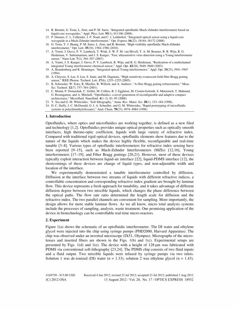
Figure 2(a) plots the interference curves at flow rate ratios of Qwater: Qethylene glycol =
15µl/min:3µl/min and Qwater: Qethylene glycol = 10µl/min:3µl/min. This plot demonstrates the flow
rate ratio changes refractive index gradient which results in a center wavelength drift of
0.35nm. A program was written in COMSOL to calculate the refractive index gradient at
different flow rates. Flesh color represents the DI-water and the carmine represents the
ethylene glycol. Color bar describes refractive index distribution. From the simulation results
in Figs. 2(b) and 2(c), the diffusivity decreases with lager flow rate ratio.
#169750 - $15.00 USD Received 4 Jun 2012; revised 23 Jul 2012; accepted 23 Jul 2012; published 2 Aug 2012(C) 2012 OSA 13 August 2012 / Vol. 20, No. 17 / OPTICS EXPRESS 18933
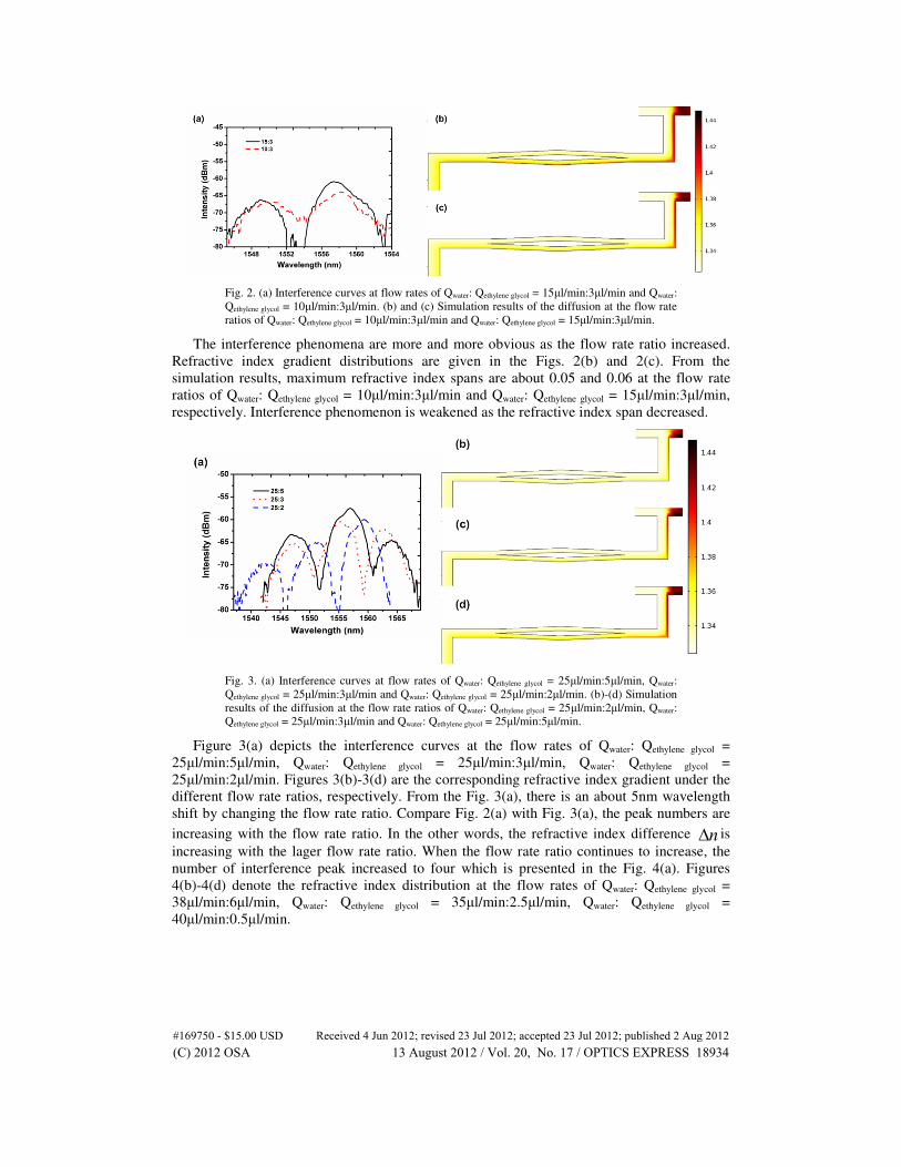
Fig. 2. (a) Interference curves at flow rates of Qwater: Qethylene glycol = 15µl/min:3µl/min and Qwater:
Qethylene glycol = 10µl/min:3µl/min. (b) and (c) Simulation results of the diffusion at the flow rate
ratios of Qwater: Qethylene glycol = 10µl/min:3µl/min and Qwater: Qethylene glycol = 15µl/min:3µl/min.
The interference phenomena are more and more obvious as the flow rate ratio increased.
Refractive index gradient distributions are given in the Figs. 2(b) and 2(c). From the
simulation results, maximum refractive index spans are about 0.05 and 0.06 at the flow rate
ratios of Qwater: Qethylene glycol = 10µl/min:3µl/min and Qwater: Qethylene glycol = 15µl/min:3µl/min,
respectively. Interference phenomenon is weakened as the refractive index span decreased.
Fig. 3. (a) Interference curves at flow rates of Qwater: Qethylene glycol = 25µl/min:5µl/min, Qwater:
Qethylene glycol = 25µl/min:3µl/min and Qwater: Qethylene glycol = 25µl/min:2µl/min. (b)-(d) Simulation
results of the diffusion at the flow rate ratios of Qwater: Qethylene glycol = 25µl/min:2µl/min, Qwater:
Qethylene glycol = 25µl/min:3µl/min and Qwater: Qethylene glycol = 25µl/min:5µl/min.
Figure 3(a) depicts the interference curves at the flow rates of Qwater: Qethylene glycol =
25µl/min:5µl/min, Qwater: Qethylene glycol = 25µl/min:3µl/min, Qwater: Qethylene glycol =
25µl/min:2µl/min. Figures 3(b)-3(d) are the corresponding refractive index gradient under the
different flow rate ratios, respectively. From the Fig. 3(a), there is an about 5nm wavelength
shift by changing the flow rate ratio. Compare Fig. 2(a) with Fig. 3(a), the peak numbers are
increasing with the flow rate ratio. In the other words, the refractive index difference n∆ is
increasing with the lager flow rate ratio. When the flow rate ratio continues to increase, the
number of interference peak increased to four which is presented in the Fig. 4(a). Figures
4(b)-4(d) denote the refractive index distribution at the flow rates of Qwater: Qethylene glycol =
38µl/min:6µl/min, Qwater: Qethylene glycol = 35µl/min:2.5µl/min, Qwater: Qethylene glycol =
40µl/min:0.5µl/min.
#169750 - $15.00 USD Received 4 Jun 2012; revised 23 Jul 2012; accepted 23 Jul 2012; published 2 Aug 2012(C) 2012 OSA 13 August 2012 / Vol. 20, No. 17 / OPTICS EXPRESS 18934

Fig. 4. (a) Interference curves at flow rates of Qwater: Qethylene glycol = 40µl/min:0.5µl/min, Qwater:
Qethylene glycol = 38µl/min:6µl/min and Qwater: Qethylene glycol = 35µl/min:2.5µl/min. (b)-(d)
Simulation results of the diffusion at the flow rates ratio of Qwater: Qethylene glycol =
38µl/min:6µl/min, Qwater: Qethylene glycol = 35µl/min:2.5µl/min and Qwater: Qethylene glycol =
40µl/min:0.5µl/min.
Figure 5 gives micrographs of the different location of the interface and the corresponding
refractive index distribution. It can be observed that the interference was controlled by flow
rates of the two miscible liquids. Refractive index gradient manipulate the optical path
difference. Our device detects small variation of the refractive index difference and has no
restriction for refractive index of samples. It also can be used to measure the reaction degree
of two liquids in biochemistry in terms of the peak numbers. In theory, the results can be
optimized by larger flow rate ratio. However, it will lead to the instability of the laminar flow
interface.
The device has many applications, such as tunable filter, real-time micro-reactor and
sensor. The experimental results show that it has a sensitivity of 139 nm per refractive index
unit (RIU). The key parameter sensitivity needs to be optimized if it acts as a sensor. Acting
as an optical switch, the response speed needs to be improved, because the stability of laminar
flow takes several seconds when the flow rate changes.
Fig. 5. [1]-[4] Different locations of interface. (a)-(d) are the corresponding refractive index
distributions.
#169750 - $15.00 USD Received 4 Jun 2012; revised 23 Jul 2012; accepted 23 Jul 2012; published 2 Aug 2012(C) 2012 OSA 13 August 2012 / Vol. 20, No. 17 / OPTICS EXPRESS 18935

4. Conclusion
This letter describes a tunable optofluidic interferometer controlled by liquid diffusion.
Several nanometers wavelength drift was achieved in our experiment. It is relatively easy to
vary the refractive index difference n∆ and avoid changing the liquid types. In contrast to
most microfluidic interferometers, our device features exact and easy controllability and
simple structure. Tunable method in our experiment is simple and direct. The peak numbers of
the interference curves are increasing with the flow rate ratio. Such an interferometer will
pave the way for microfluidic components that used for biochemical tests in fully integrated
and highly compact sensing system.
Acknowledgments
This research was supported by the National Natural Science Foundation of China (Grant No.
61125503) and the Foundation for Development of Science and Technology of Shanghai
(Grant No. 11XD1402600, No. 10JC1407200).
#169750 - $15.00 USD Received 4 Jun 2012; revised 23 Jul 2012; accepted 23 Jul 2012; published 2 Aug 2012(C) 2012 OSA 13 August 2012 / Vol. 20, No. 17 / OPTICS EXPRESS 18936