an exploration of the effects of moods in attitude …
TRANSCRIPT

EFFECT OF TOOL ECCENTRICITY ON THE STATIC AND FATIGUE STRENGTH OF THE JOINT MADE BY
MECHANICAL CLINCHING PROCESS
KAM HENG KEONG
MASTER OF ENGINEERING SCIENCE
LEE KONG CHIAN FACULTY OF ENGINEERING AND SCIENCE
UNIVERSITI TUNKU ABDUL RAHMAN MARCH 2015
EFFECT OF TOOL ECCENTRICITY ON THE STATIC AND FATIGUE
STRENGTH OF THE JOINT MADE BY MECHANICAL CLINCHING
PROCESS
By
KAM HENG KEONG
A dissertation submitted to the Department of Mechanical and Material
Engineering,
Lee Kong Chian Faculty of Engineering and Science,
Universiti Tunku Abdul Rahman,
in partial fulfillment of the requirements for the degree of
Master of Engineering Science
March 2015

ii
ABSTRACT
EFFECT OF TOOL ECCENTRICITY ON THE STATIC AND FATIGUE
STRENGTH OF THE JOINT MADE BY MECHANICAL CLINCHING
PROCESS
Kam Heng Keong
The effect of tool eccentricity on the joint strength in clinching process was
investigated. The objective is to understand the mechanical behaviour of the
clinched joint where proper control on the alignment setting of tools can be
considered. In this research, a clinching process to form a round joint was
carried out by offsetting the centre line between the upper punch and lower die.
The experimental results were compared between offset and without offset
conditions. The factors which determine the quality of joint strength such as
the interlock and the neck thickness obtained from cross section geometry
were examined by opening mode and tension-shearing mode tests. Coated
mild steel and aluminium alloy sheets were used for the evaluation. It is found
that the strength values by offset clinching exhibit variation in sinusoidal
relationship with respect to the in-plane offset direction. These values are
generally lower by 10-36% for mild steel and 60-70% for aluminium alloy.
The fatigue strength of a clinched joint with offset is generally 5-10% weaker
compared to the one without offset. Finally, a 2D rigid-plastic FEM tool is
proposed as a first attempt of approximation to investigate the formation of
interlock and also to predict the distribution of tool contact pressure caused by
the offset condition.

iii
ACKNOWLEDGEMENT
I would like to express my deep and sincere gratitude to my
supervisors, Dr. Wang Chan Chin and Dr. Lim Ying Pio. Throughout my
project, they have provided encouragement, advice, guidance, support, and
lots of good ideas. These have had a great influence on my entire project.
I wish to thank the faculty and staffs in Universiti Tunku Abdul
Rahman, for providing assistance to my project. Special thank to thank to Mr.
Chee Mun Cheng, Mr. Chee Wah Chan and Mr. Kim Haw Yap from Panasonic
Appliances Airconditioning R&D Malaysia (PAPARADMY) for supplying
clinching tools and materials to complete this research
Last but not least, I wish to thank my parents, my sister and brother-in-
law who were beside me all the time and gave me the precious support and
encouragement to complete my work and attain my ambition to earn a master
degree.

iv
APPROVAL SHEET
This dissertation entitled “EFFECT OF TOOL ECCENTRICITY ON THE
STATIC AND FATIGUE STRENGTH OF THE JOINT MADE BY
MECHANICAL CLINCHING PROCESS” was prepared by KAM HENG
KEONG and submitted as partial fulfillment of the requirements for the
degree of Master of Engineering Science at Universiti Tunku Abdul Rahman.
Approved by:
___________________________
(Dr. Wang Chan Chin)
Date:…………………..
Supervisor
Department of Mechanical and Material Engineering
Faculty of Engineering and Science
Universiti Tunku Abdul Rahman
___________________________
(Dr. Lim Ying Pio)
Date:…………………..
Co-supervisor
Department of Mechanical and Material Engineering
Faculty of Engineering and Science
Universiti Tunku Abdul Rahman
v
FACULTY OF ENGINEERING AND SCIENCE
UNIVERSITI TUNKU ABDUL RAHMAN
Date: 16th October 2014
SUBMISSION OF THESIS
It is hereby certified that KAM HENG KEONG (ID No: 11UEM06268) has
completed this thesis entitled “EFFECT OF TOOL ECCENTRICITY ON THE
STATIC AND FATIGUE STRENGTH OF THE JOINT MADE BY
MECHANICAL CLINCHING PROCESS” under the supervision of Dr. Wang
Chan Chin (Supervisor) from the Department of Mechanical & Material
Engineering, Faculty of Engineering and Science, and Dr. Lim Ying Pio (Co-
Supervisor) from the Department of Mechanical & Material Engineering, Faculty
of Engineering Science.
I understand that University will upload softcopy of my thesis in pdf format into
UTAR Institutional Repository, which may be made accessible to UTAR
community and public.
Yours truly,
____________________
(KAM HENG KEONG)
vi
DECLARATION
I hereby declare that the dissertation is based on my original work except for
quotations and citations which have been duly acknowledged. I also declare
that it has not been previously or concurrently submitted for any other degree
at UTAR or other institutions.
Name KAM HENG KEONG a
Date 24th
March 2014 a

viii
TABLE OF CONTENTS
Page
ABSTRACT ii
ACKNOWLEDGEMENT iii
APPROVAL SHEET iv
SUBMISSION SHEET v
DECLARATION vi
TABLE OF CONTENTS vii
LIST OF TABLES xiii
LIST OF FIGURES xvi
LIST OF ABBREVIATIONS/NOTATION/GLOSSARY OF TERMS xix
CHAPTER
1.0 INTRODUCTION 1
1.1 Research Background 1
1.2 Research Objectives 6
1.3 Thesis Overview 6
2.0 LITERATURE REVIEW 8
2.1 Mechanical Assembly 8
2.1.1 Welding 8
2.1.2 Self-piercing Riveting 9
2.1.3 Mechanical Clinching 11
2.1.4 Metal Joining Technique Comparison 12
2.2 Mechanical Clinching Joint Strength Parameters 14
2.2.1 Material Properties and Thickness 14
2.2.2 Tool Geometry 17
2.3 Quality Assurance of Clinched Joint 16
2.3.1 Automatic Real-time Quality Control
System 18
2.3.2 Non-destructive Testing 19
2.3.3 Destructive Testing 20
3.0 METHODOLOGY 22
3.1 Tensile Test 22
3.2 Experiment Setup 23
3.3 Clinching Process Monitoring 26
3.4 Study of Clinched Joint Cross Section 26
3.5 Loading Tests for Static and Fatigue Strength 27
3.6 FEM Model for Offset Clinching 30
4.0 RESULTS AND DISCUSSION 32
4.1 Offset Clinching 32
4.2 Static Strength Test 39
viii
4.2.1 Static Strength and Failure Modes 39
4.2.2 Static Strength Test for Offset Clinching 42
4.3 Fatigue Strength Test 46
4.4 Finite Element Simulation for Offset Clinching 47
5.0 CONCLUSIONS AND FUTURE WORKS 53
5.1 Conclusions 53
5.2 Future works 55
REFERENCES 57
APPENDICES 63
A Tensile Test Result 63
B Study of Clinched Joint of Commercial Product 64
C Experiment Apparatus 66
D List of Publication 67
ix
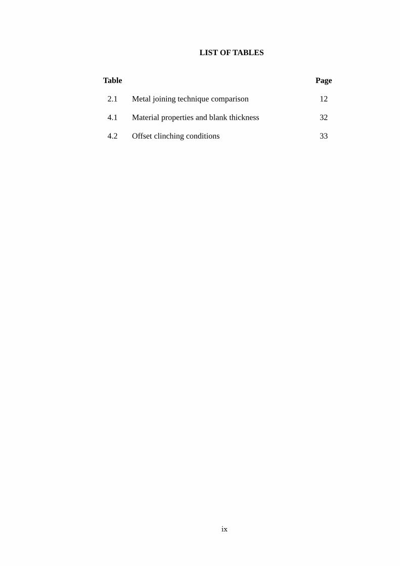
LIST OF TABLES
Table
2.1
Metal joining technique comparison
Page
12
4.1 Material properties and blank thickness
32
4.2 Offset clinching conditions 33

x
LIST OF FIGURES
Figures
Page
1.1 The cross section of a clinched joint and parameter
terms, interlock ts, neck thickness tn, reduction of
bottom thickness rb.
2
1.2 Failure Modes (a) Button Separation (b) Neck
Failure
3
1.3 Clinched structure and pulling force direction for
strength test
4
1.4 Cross section view of clinched joint (sample from
commercial product)
4
2.1 Spot welding
9
2.2 Self-piercing riveting
10
2.3 Mechanical clinching (TOX®PRESSOTECHNIK,
2009)
11
2.4 Neck fracture mode analysis of clinched joint
15
2.5 Button separation mode analysis of clinched joint
15
2.6 Flow chart of joint strength and joint failure mode
identification
16
2.7 Punch load curve collected by real-time process
control system [TOX® GmbH]
18
2.8 Tolerance gauge
19
2.9 Monitor Joint Quality for Tog-L-Loc and Lance-
N-Loc
20
2.10 Joined sheets used for destructive testing
(a) tension shearing test (b) cross-tension test
20
3.1 Instron 5582 universal testing machine
22
3.2 Tensile test specimen (JIS K7113-1)
23
3.3 Layout of offset clinching tool
24
3.4 Tool center position and loading point
24
xi
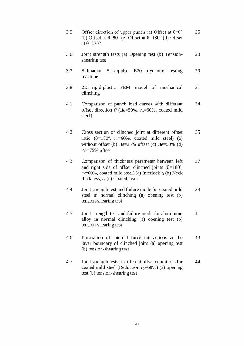
3.5 Offset direction of upper punch (a) Offset at θ=0°
(b) Offset at θ=90° (c) Offset at θ=180° (d) Offset
at θ=270°
25
3.6 Joint strength tests (a) Opening test (b) Tension-
shearing test
28
3.7 Shimadzu Servopulse E20 dynamic testing
machine
29
3.8 2D rigid-plastic FEM model of mechanical
clinching
31
4.1 Comparison of punch load curves with different
offset direction θ (e=50%, rb=60%, coated mild
steel)
34
4.2 Cross section of clinched joint at different offset
ratio (=180º, rb=60%, coated mild steel) (a)
without offset (b) e=25% offset (c) e=50% (d)
e=75% offset
35
4.3 Comparison of thickness parameter between left
and right side of offset clinched joints (=180º,
rb=60%, coated mild steel) (a) Interlock ts (b) Neck
thickness, tn (c) Coated layer
37
4.4 Joint strength test and failure mode for coated mild
steel in normal clinching (a) opening test (b)
tension-shearing test
39
4.5 Joint strength test and failure mode for aluminium
alloy in normal clinching (a) opening test (b)
tension-shearing test
41
4.6 Illustration of internal force interactions at the
layer boundary of clinched joint (a) opening test
(b) tension-shearing test
43
4.7 Joint strength tests at different offset conditions for
coated mild steel (Reduction rb=60%) (a) opening
test (b) tension-shearing test
44

xii
4.8 Joint strength tests at different offset conditions for
aluminium alloy (Reduction rb=60%) (a) opening
test (b) tension-shearing test
45
4.9 Relationship between percentage of maximum
pulling force and number of cycles in fatigue
tension-shearing test for coated mild steel
(Reduction rb=60%)
47
4.10 Comparison of punch load between experimental
and simulated results (Reduction rb=50%, Coated
mild steel)
48
4.11 Comparison of Cross section and formation of
interlock between experimental and simulated
results (a) cross section (b) interlock
49
4.12 Offset clinching simulation by FEM in plain-strain
model (a) experiment result (b) simulation result
50
4.13 Tooling surface pressure distribution (a) without
offset (b) with offset
51
4.14 Effect of tooling eccentricity to the punch
localized maximum pressure
52
4.15 Cracked punch 52

1
CHAPTER 1
INTRODUCTION
1.1 Research Background
Mechanical clinching is a cold joining process commonly used to join
several metal sheet components into a single piece structure by local
hemming. This method is widely used due to its short time and low running
cost merits where no additional materials are needed for riveting or heat
energy in welding. Besides, the process also acquires flexibleness in joining
different types of sheet metal such as aluminium alloy with steel to cut down
weight of product’s structure such as vehicle and electrical appliances in the
industry. Various researches in the mechanical clinching method had been
carried out, Varis (2003) inspected the joint strength of various shapes to
investigate the suitability for making building frames with high strength
structural steel. Varis (2006) continued to study on the economic merit from
the aspect of tool service lifespan by comparing the unit cost produced by the
mechanical clinching over the self-pierce riveting. Varis and Lepistö (2003)
discovered some important parameters for mechanical clinching by using
experimental method and finite element method (FEM). Coppieters et al.
(2011) reported a set of analytical methods by simplifying the material
geometries and stresses to predict the pull-out strength in box-test. Lee et al.
(2010) utilized FEM on tool design in order to obtain higher joint strength
2
which fulfils the requirement of automotive industry. Abe et al. (2011)
declared that the joint strength of rectangular shape shows higher values than
the one of round shape. Abe et al. (2012) introduced a metal flow control
method to overcome fracture failure of clinching high strength steel with
aluminium alloy sheet. Abe et al (2007) studied the method to join aluminium
alloy with mild steel sheets by investigating the flow stress of deformed
sheets. Mori et al. (2012) compared the fatigue strength between mechanical
clinching and self-pierce riveting, and explained the mechanism of superiority
by mechanical clinching method. Carbini et al. (2006) found that a tensile-
shear loaded clinched joint can last more than 2 x 10⁷ number of cycles at 50%
of maximum joint strength.
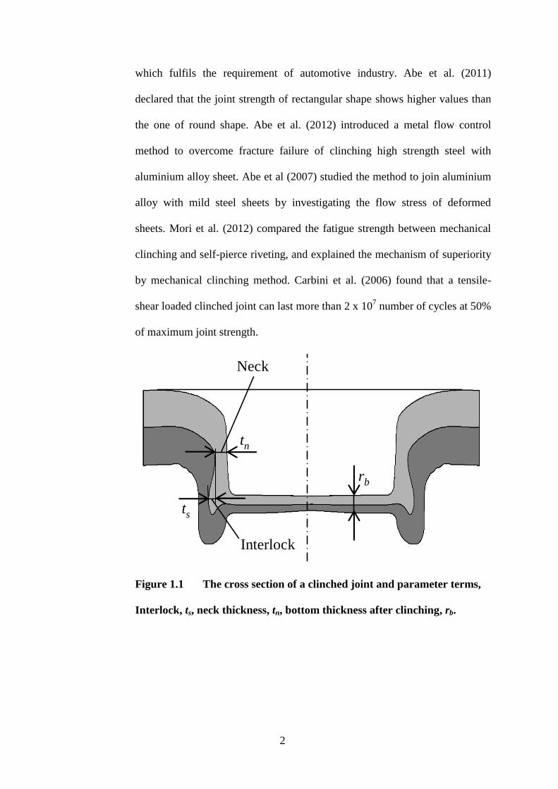
Figure 1.1 The cross section of a clinched joint and parameter terms,
Interlock, ts, neck thickness, tn, bottom thickness after clinching, rb.
tn
ts
rb
Interlock
Neck
3
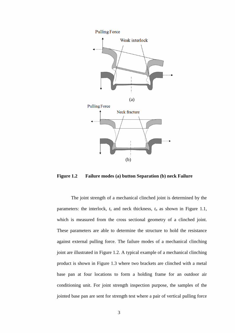
(a)
(b)
Figure 1.2 Failure modes (a) button Separation (b) neck Failure
The joint strength of a mechanical clinched joint is determined by the
parameters: the interlock, ts and neck thickness, tn as shown in Figure 1.1,
which is measured from the cross sectional geometry of a clinched joint.
These parameters are able to determine the structure to hold the resistance
against external pulling force. The failure modes of a mechanical clinching
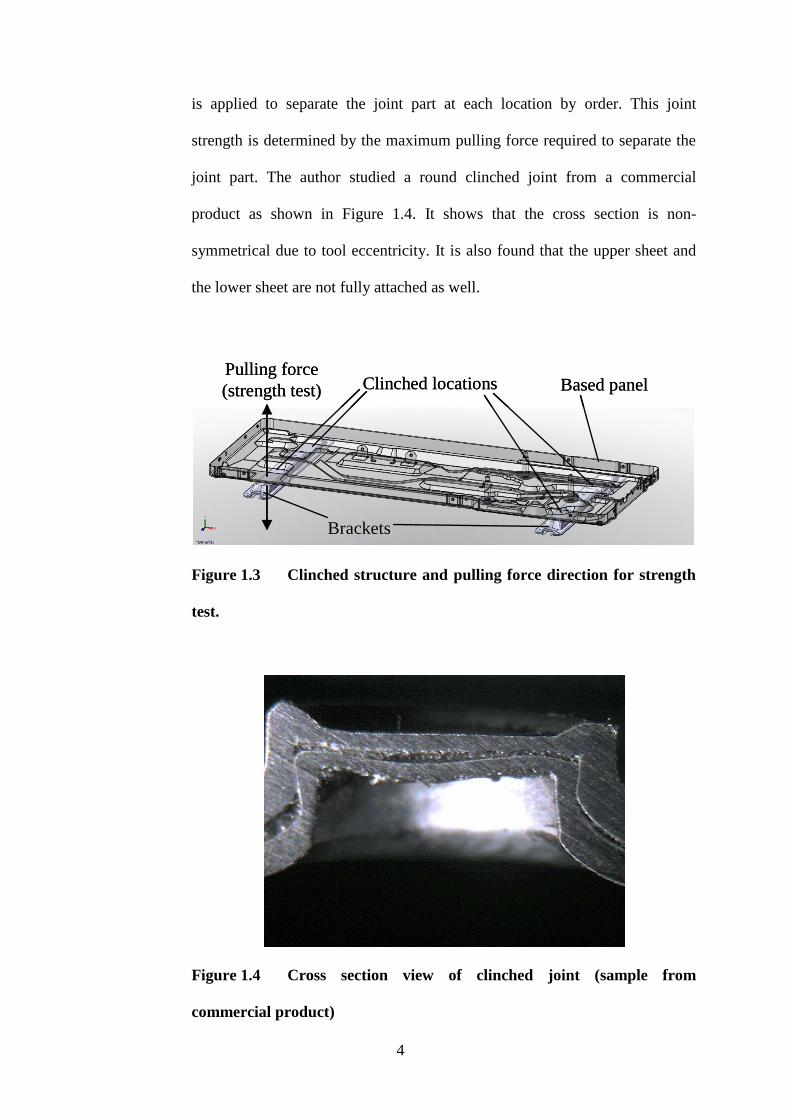
joint are illustrated in Figure 1.2. A typical example of a mechanical clinching
product is shown in Figure 1.3 where two brackets are clinched with a metal
base pan at four locations to form a holding frame for an outdoor air
conditioning unit. For joint strength inspection purpose, the samples of the
jointed base pan are sent for strength test where a pair of vertical pulling force
4
is applied to separate the joint part at each location by order. This joint
strength is determined by the maximum pulling force required to separate the
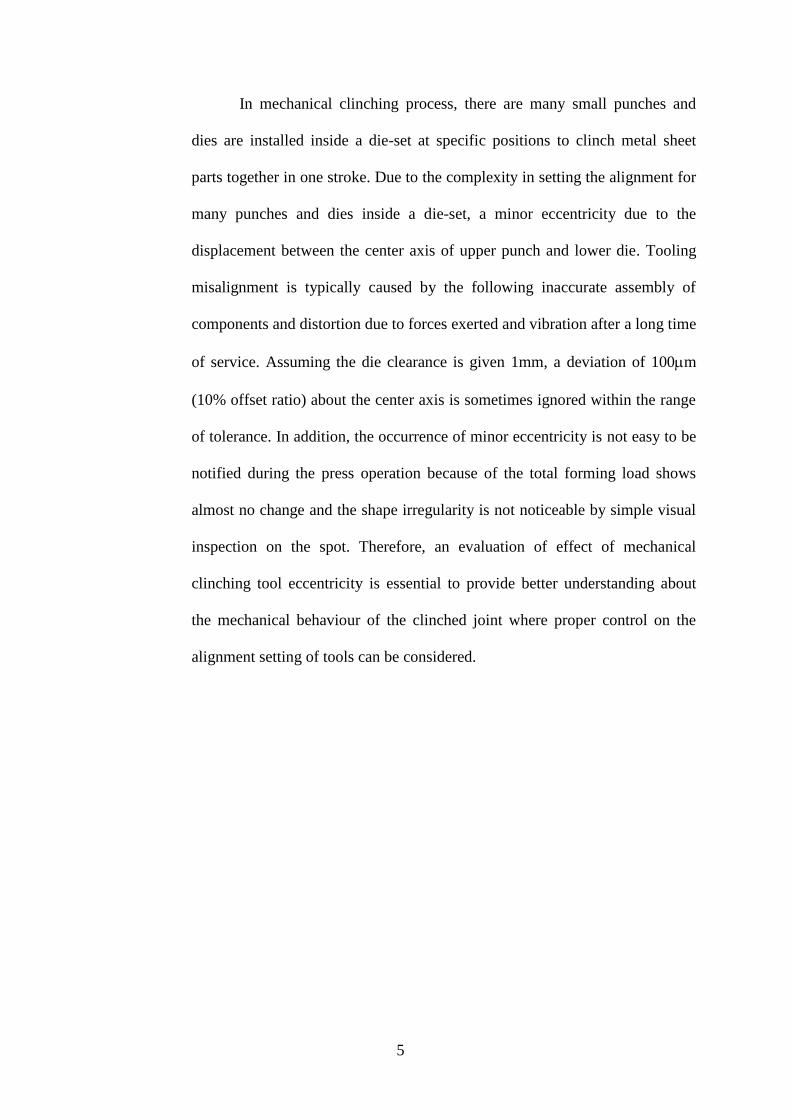
joint part. The author studied a round clinched joint from a commercial
product as shown in Figure 1.4. It shows that the cross section is non-
symmetrical due to tool eccentricity. It is also found that the upper sheet and
the lower sheet are not fully attached as well.
Figure 1.3 Clinched structure and pulling force direction for strength
test.
Figure 1.4 Cross section view of clinched joint (sample from
commercial product)
Clinched locations
Brackets
Based panelPulling force
(strength test) Clinched locations
Brackets
Based panelPulling force
(strength test)
5
In mechanical clinching process, there are many small punches and
dies are installed inside a die-set at specific positions to clinch metal sheet
parts together in one stroke. Due to the complexity in setting the alignment for
many punches and dies inside a die-set, a minor eccentricity due to the
displacement between the center axis of upper punch and lower die. Tooling
misalignment is typically caused by the following inaccurate assembly of
components and distortion due to forces exerted and vibration after a long time
of service. Assuming the die clearance is given 1mm, a deviation of 100m
(10% offset ratio) about the center axis is sometimes ignored within the range
of tolerance. In addition, the occurrence of minor eccentricity is not easy to be
notified during the press operation because of the total forming load shows
almost no change and the shape irregularity is not noticeable by simple visual
inspection on the spot. Therefore, an evaluation of effect of mechanical
clinching tool eccentricity is essential to provide better understanding about
the mechanical behaviour of the clinched joint where proper control on the
alignment setting of tools can be considered.

6
1.2 Research Objectives
The objectives of this study are:
1. Investigate the deviation of tool eccentricity in mechanical clinching
by evaluating the joint strength (static case) in various conditions of
tool offset and to define suitable allowance.
2. Provide a better understanding about the mechanical behavior of the
clinched joint where the quality of joint strength can be referred to
assist proper setting of tool alignment.
1.3 Thesis Overview
Outline of this dissertation are as shown below,
Chapter 1 presents a brief introduction, problem statement, objectives
to be achieved and the layout of the thesis.
Chapter 2 describes a literature review which includes an introduction
to mechanical assembling methods such as welding, self-pierce riveting and
mechanical clinching. Review on journals on different studies on the
behaviour of mechanical clinching.
Chapter 3 covers the experimental setting of mechanical clinching used
in this study, including the geometries of mechanical clinching tools, tensile
test on the sheet metals, clinching joint loading test and fatigue test,

7
application of FEM software to predict the effect of tooling eccentricity on
mechanical clinching joint.
Chapter 4 discussed the result of mechanical clinching joint under
different clinching condition. Data collected from different tests was plotted
on graphs to study the outcome of mechanical clinching joint under different
clinching condition. The discussion of the results is included in this section as
well.
Chapter 5 describes the conclusions and the contributions of this
dissertation.
Chapter 6 expresses the future prospect of current research.
8
CHAPTER 2
LITERATURE REVIEW
2.1 Mechanical Assembly
There are a lot of products which are made of more than one parts,
engineers need to search for an effective way to assemble the parts into a
component. Several joining methods are used in mechanical assembly to
mechanically join two or more parts together. Mechanical joining can be
categorized into methods of that are temporally such as fastening screws and
that are permanent joining such as rivets. The focus of this research work is in
the mechanical clinching which is one of the permanent joining method.
2.1.1 Welding
In the welding process, two or more parts are heated and melted or
forced together, causing the parts to join as one. Therefore, a lot of energy is
required to heat up the material and fumes are produced during the welding
process. In some welding methods, a filler material is added to make the
joining of the materials easier. One of the limitations of welding process is that
this method is not suitable to join dissimilar material because of different
material properties especially melting point. Various types of welding

9
operations are used in the industries, such as the spot welding, arch welding,
resistance welding and friction stir welding.
Figure 2.1 Spot welding
2.1.2 Self-piercing Riveting
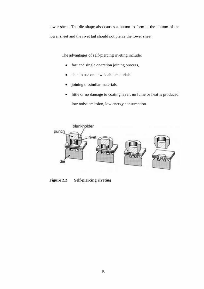
Self-piercing riveting is a one-stroke mechanical fastening process
which is for point joining sheet material such as steels and aluminium alloys.
This process generally uses a semi-tubular rivet to join the sheets in a
mechanical joint. In addition, there is also a process variant which utilises
solid rivets.
As the name suggests, pre-processing holes are not necessary, allowing
the joint to be done more rapidly in one operation. The process starts by
clamping the sheets between the die and the blankholder. The semi-tubular
shaped rivet is punched into the sheet metals that are to be joined between a
punch and die in a pressing tool. Mechanical interlock is formed when the
rivet pierces the upper sheet and the die shape causes the rivet to flare in the
10
lower sheet. The die shape also causes a button to form at the bottom of the
lower sheet and the rivet tail should not pierce the lower sheet.
The advantages of self-piercing riveting include:
fast and single operation joining process,
able to use on unweldable materials
joining dissimilar materials,
little or no damage to coating layer, no fume or heat is produced,
low noise emission, low energy consumption.
Figure 2.2 Self-piercing riveting

11
2.1.3 Mechanical Clinching
Clinching (press joining) is a reliable method for joining metal sheets,
tubes and profiles. This permanent joint is created by using cold forming
technique, without using additional parts or welds. This method offers a
decrease in both production and manufacturing cost due to the elimination of
the additional parts and 60% reduction of energy used relative to welding.
(P.Nesi, 2004)
Figure 2.3 Mechanical clinching (TOX®PRESSOTECHNIK, 2009)
The tools require to form a mechanical clinching joint are punch and
die. The punch squeezes the two layers of sheet metal into the die. Ultimately
the upper sheet forms an interlock within the lower sheet.
Clinching is widely used in the automotive, appliances and electronics
industries, where it replaces spot welding in common. Clinching is a cold
forming process which requires no electricity and heat. Clinching provides
quieter, cleaner and safer working environment for the operators. Maximum
lifespan for clinching tools is 300,000 joints and its application for numerous
material joining makes it a very economical process (Varis, J., 2006). The

12
operational life of clinching tools can be improved by modifying tool
geometry and/or material, and surface treatment of the fastening tool (Lothar
Budde, 1994). Clinching has become more popular in joining aluminium
panels due to the problems encountered with spot welding of aluminium.
2.1.4 Metal Joining Technique Comparison
The comparisons of clinching, self-piercing riveting and welding under
different criteria are stated in Table 2.1.
Table 2.1 Metal joining technique comparison
Clinching
Self-piercing
riveting
Welding
Corrosion of coated
material
Little Little High
Joint and strength
alteration at joining
None None Yes
Dynamic load-resistance
(shearing)
Very good Very good Less good
Static load-resistance
(shearing)
Good Very good Very good
Process combined with
bonding
Optimum Optimum Poor
Edges-burring-splinters None None
None

13
Joining consumables
required
None Punch rivet None
Additional working
processes
None Supply
Post
retreatment
of treated
surface
Cost per joint Very little Little High
Energy consumption Little Little Very high
Economy Very good Good Less good
Handling
Very
simple
Simple Simple
Reproducibility Very good Very good Satisfactory
Dependence of joint
result on surface quality
Little None High
Pre-processing None None
Washing,
etching
Among the advantages of mechanical clinching, Varis (2006) draws a
conclusion that mechanical clinching is preferred over self-pierceing riveting
and welding in term of economic merit which has a lower production cost in
the aspect of tool service lifespan.

14
2.2 Mechanical Clinching Joint Strength Parameters
Several researches had been carried out to study the factors that
determine the strength of a mechanical clinching joint. In general, the strength
of a mechanical clinching joint is directly proportional to the joint size, the
thickness and strength of the blank material.
2.2.1 Material Properties and Thickness
Mucha et al (2011) compared the clinching joint sheering strength of
two different materials and made a conclusion that the sheering strength of the
clinch joint made of the stronger material is higher than the relatively weaker
material. He also commented that thicker sheet metal should be used as the
upper sheet in order to obtain higher clinching joint strength when joining
materials of different thickness. Neck fracture mode and button separation
mode are always found during the joint strength testing. Lee et al (2010)
proposed Equation 2.1 and 2.2 to predict joint strength and failure mode. From
the equation shown, the joint strength is proportional to fracture stress of the
material in neck fracture mode and flow stress in the button separation mode.
Besides, these two equations are proportional to interlock, ts and neck
thickness, tn.

15
Figure 2.4 Neck fracture mode analysis of clinched joint
Where is the fracture stress of the upper sheet
is the projection area of the neck part
Rp is the clinching punch radius
is the neck-thickness
Figure 2.5 Button separation mode analysis of clinched joint
FN
FB
ts

16
(2.2)
Where is the average flow stress in the clinched region stress
is the length of the interlock
is the friction coefficient
Since the strength and failure mode of a clinched joint is determined by
the material strength, neck thickness, tn and interlock, ts, Figure 2.6 shows the
flow chart proposed by Lee et al (2010) to predict the strength of a clinched
joint and its failure mode. Equation 2.1 and 2.2 are applied to calculate the
strength and failure mode of a clinched joint. A clinched joint will fail at a
lower calculated joint strength value from the two equations shown above.
Figure 2.6 Flow chart of joint strength and joint failure mode
identification

17
2.2.2 Tool Geometry
The joinability of the sheet metals is greatly affected by the geometry
of the clinching punch and die especially for the metals with low ductility.
Several researches had been carried out on the study the effect of tool
geometry improving the joinability of high strength steels by modifying the
geometry of the clinching die (Varis, J.P..2003, Abe et al. 2008, Abe et
al.2012). It was also reported that the geometry will influence the material
flow of the sheet metals especially at the neck thickness, tn and interlock, ts as
shown in Figure 1.1. In general, the segment that stretches the most occurs at
the neck part. Lower strain at the neck part is preferred in order to avoid
fracture during forming and under loading. Large strain deformation will also
wear out the coating layer of clinched joint. This will greatly weakens the
corrosion resistance of the clinched joint. By modifying the clinching die,
corrosion resistance can be increased by 40% (Abe et al, 2010). In order to
achieve the optimum joint strength, FEM is used to predict the outcome by
modifying the geometry of punch and die. Due to the curiosity about the effect
of tools geometry to the mechanical clinched joint strength, M. Oudjene and
L.Ben-Ayed (2008) applied Taguchi Method to study on how parameters of
the tools geometry together with FEM software to compromise the shape of
the punch and die in order to produce a better quality clinched joint. The result
of this method showed an increase of separation force when comparing the
initial tools geometry and with the new tools geometry obtained from the
Taguchi Method.
18
2.3 Quality Assurance of Clinched Joint
The quality of a mechanical clinching joint can be reviewed during the
clinching process by using an automatic real-time quality control system, and
after the clinching process by non-destructive and destructive testing.
2.3.1 Automatic Real-time Quality Control System
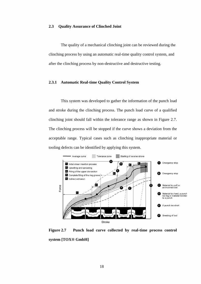
This system was developed to gather the information of the punch load
and stroke during the clinching process. The punch load curve of a qualified
clinching joint should fall within the tolerance range as shown in Figure 2.7.
The clinching process will be stopped if the curve shows a deviation from the
acceptable range. Typical cases such as clinching inappropriate material or
tooling defects can be identified by applying this system.
Figure 2.7 Punch load curve collected by real-time process control
system [TOX® GmbH]
19
2.3.2 Non-destructive Testing
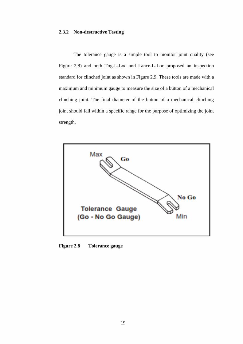
The tolerance gauge is a simple tool to monitor joint quality (see
Figure 2.8) and both Tog-L-Loc and Lance-L-Loc proposed an inspection
standard for clinched joint as shown in Figure 2.9. These tools are made with a
maximum and minimum gauge to measure the size of a button of a mechanical
clinching joint. The final diameter of the button of a mechanical clinching
joint should fall within a specific range for the purpose of optimizing the joint
strength.
Figure 2.8 Tolerance gauge
20
Figure 2.9 Joint quality inspection by Tog-L-Loc and Lance-N-Loc
2.3.3 Destructive Testing
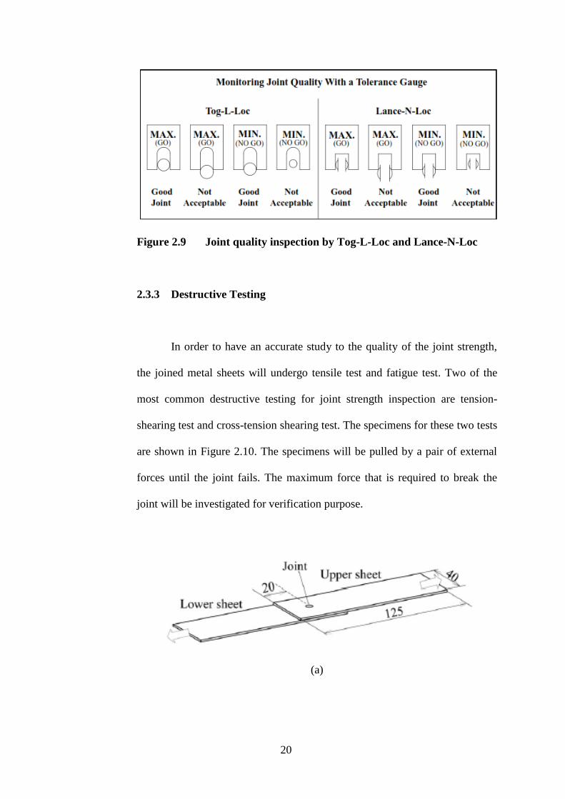
In order to have an accurate study to the quality of the joint strength,
the joined metal sheets will undergo tensile test and fatigue test. Two of the
most common destructive testing for joint strength inspection are tension-
shearing test and cross-tension shearing test. The specimens for these two tests
are shown in Figure 2.10. The specimens will be pulled by a pair of external
forces until the joint fails. The maximum force that is required to break the
joint will be investigated for verification purpose.
(a)

21
(b)
Figure 2.10 Joined sheets used for destructive testing (a) tension-
shearing test (b) cross-tension test

22
CHAPTER 3
METHODOLOGY
3.1 Tensile Test
Tensile test is carried out by using Instron 5582 universal testing
machine to obtain the true stress and true strain of the sheet metals. The sheet
metals are coated mild steel GL400 FN AZ150 and aluminium alloy
A1100H14. The specimens are cut into the shape as shown in Figure 3.2 for
tensile test.
Figure 3.1 Instron 5582 universal testing machine
23
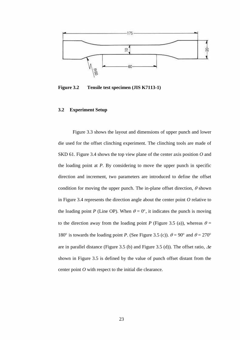
Figure 3.2 Tensile test specimen (JIS K7113-1)
3.2 Experiment Setup
Figure 3.3 shows the layout and dimensions of upper punch and lower
die used for the offset clinching experiment. The clinching tools are made of
SKD 61. Figure 3.4 shows the top view plane of the center axis position O and
the loading point at P. By considering to move the upper punch in specific
direction and increment, two parameters are introduced to define the offset
condition for moving the upper punch. The in-plane offset direction, shown
in Figure 3.4 represents the direction angle about the center point O relative to
the loading point P (Line OP). When = 0, it indicates the punch is moving
to the direction away from the loading point P (Figure 3.5 (a)), whereas =
180 is towards the loading point P. (See Figure 3.5 (c)). = 90 and = 270
are in parallel distance (Figure 3.5 (b) and Figure 3.5 (d)). The offset ratio, e
shown in Figure 3.5 is defined by the value of punch offset distant from the
center point O with respect to the initial die clearance.

24
Figure 3.3 Layout and dimension of clinching tool
Figure 3.4 Tool center position and loading point
lower die diameter
upper punch diameter
Die clearanceBlank
Fs
Fo
Fo
Tension-
shearing
force
Opening force
100
20
0°
90°
180°
270°
Direction angle θ
O P
lower die diameter
upper punch diameter
Die clearanceBlank
Fs
Fo
Fo
Tension-
shearing
force
Opening force
100
20
0°
90°
180°
270°
Direction angle θ
O P

25
(a) (b)
(c) (d)
Figure 3.5 Offset direction of upper punch (a) Offset at θ = 0° (b)
Offset at θ = 90° (c) Offset at θ = 180° (d) Offset at θ = 270°
upper punch
center point
0°
90°
180°
270°
e
0°
90°
180°
270°
e
OO
upper punch
center point
0°
90°
180°
270°
e
0°
90°
180°
270°
e
OO
0°
90°
180°
270°
e
0°
90°
180°
270°
e
0°
90°
180°
270°
e
0°
90°
180°
270°
e
26
Two alignment condition is setup in this clinching experiment in order
to study the effect of tool eccentricity to mechanical clinching joint. These
conditions are:
a) Without offset (perfectly aligned punch and die setting)
b) With offsetting the punch with 0.25mm, 0.5mm and 0.75mm (25%,
50% and 75% of the clearance) to different orientation of angles
(0º, 90º, 180º and 270º)
3.3 Clinching Process Monitoring
Instron 5582 universal testing machine is used to perform the clinching
process with the tools shown in Figure 3.3. Forming load history and stroke
were recorded for the clinching process under different forming conditions.
3.4 Study of Clinched Joint Cross Section
Different sheet metals of (aluminium with aluminium and steel with
steel) 1.0mm and 1.1mm thickness are prepared with standard dimension of
100mm x 20mm. The cross sections of the joints are then observed to analyze
the material flow. The punch stroke is varied to study the relation between
reduction of bottom thickness, rb and clinch joint interlock, ts.

27
3.5 Loading Tests for Static and Fatigue Strength
Tensile tests are conducted to evaluate the strength of clinched joint
specimens with offset and without offset conditions. Two type of loading
mode (See Figure 3.6), i.e., opening test and tension-shearing test are
considered for the evaluation. The maximum force in opening test, Fo and
tension-shearing test, Fs are measured until the joint structure starts to fail. The
opening mode chosen in present research is mainly because is much
convenient as it is similar to the inspection procedure carried out by the
industry in Figure 1.3.

28
(a) (b)
Figure 3.6 Joint strength tests (a) Opening test (b) tension-shearing
test
FsFo
FoFs
Clinched joint
FsFo
FoFs
Clinched joint
29
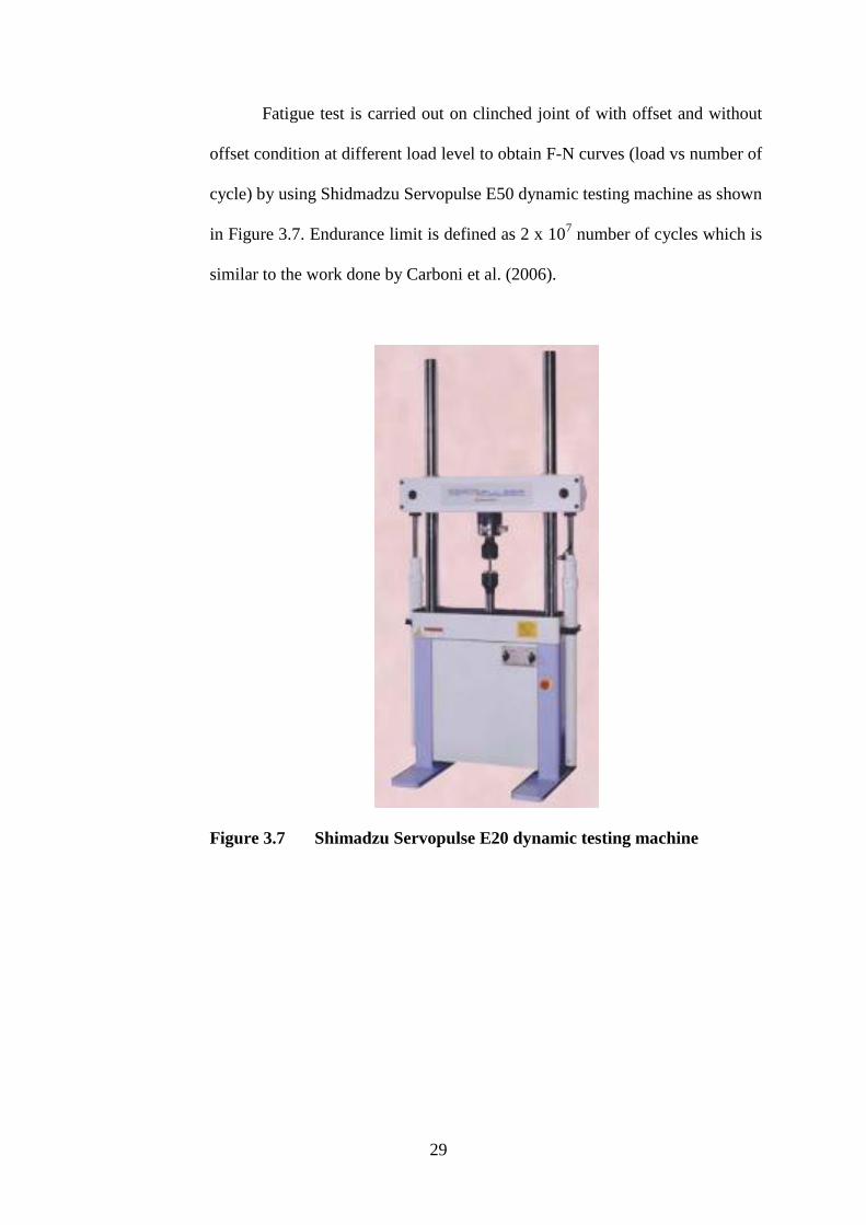
Fatigue test is carried out on clinched joint of with offset and without
offset condition at different load level to obtain F-N curves (load vs number of
cycle) by using Shidmadzu Servopulse E50 dynamic testing machine as shown
in Figure 3.7. Endurance limit is defined as 2 x 10⁷ number of cycles which is
similar to the work done by Carboni et al. (2006).
Figure 3.7 Shimadzu Servopulse E20 dynamic testing machine
30
3.6 FEM Model for Offset Clinching
The finite element analysis is applied to investigate the formation of
interlock and also to examine the distribution pattern of contact surface
pressure caused by the offset condition. In this research, a 2-D rigid-plastic
FEM code developed by Osakada et al. (1982) with space elements scheme
implemented by Wang (2009) is used as first attempt to simulate the plastic
deformation of sheet metal in clinching process. Axi-symmetric and plane-
strain models are applied for the case without offset and the case with offset,
respectively. Further attempt is made to simplify the FEM model by assuming
no slipping and detachment are allowed between the upper sheet layer and
lower sheet layer during the process takes place and the blanks are made of
same material. By these assumptions, the upper layer and lower layer can be
treated as a single deformable body in finite element analysis. However, in this
case, a line is drawn to visually represent the two layers. Figure 3.8 shows the
FEM model for the simulating the clinching process.

31
Figure 3.8 2D rigid-plastic FEM model of mechanical clinching
Upper punchBlank holder
Lower die
Blank
(Before) (After)

32
CHAPTER 4
RESULTS AND DISCUSSION
4.1 Offset Clinching
In this research, two types of material used for the blanks are parepared
for comparison purpose. Table 3.1 shows the material properties and blank
thickness and Table 3.2 shows the offset conditions and blank size for
implementation of clinching tests.
Table 4.1 Material properties and blank thickness.
Coated mild steel
GL400 FN AZ150
Aluminium alloy
A1100 H14
Thickness (mm) 1.1 1.0
Yield Strength (MPa) 250 118
Tensile Strength (MPa) 380 120
Flow stress (MPa) 32.0503 024.0138
Elongation (%) 28 18
Coating Zinc (15µm) -
33
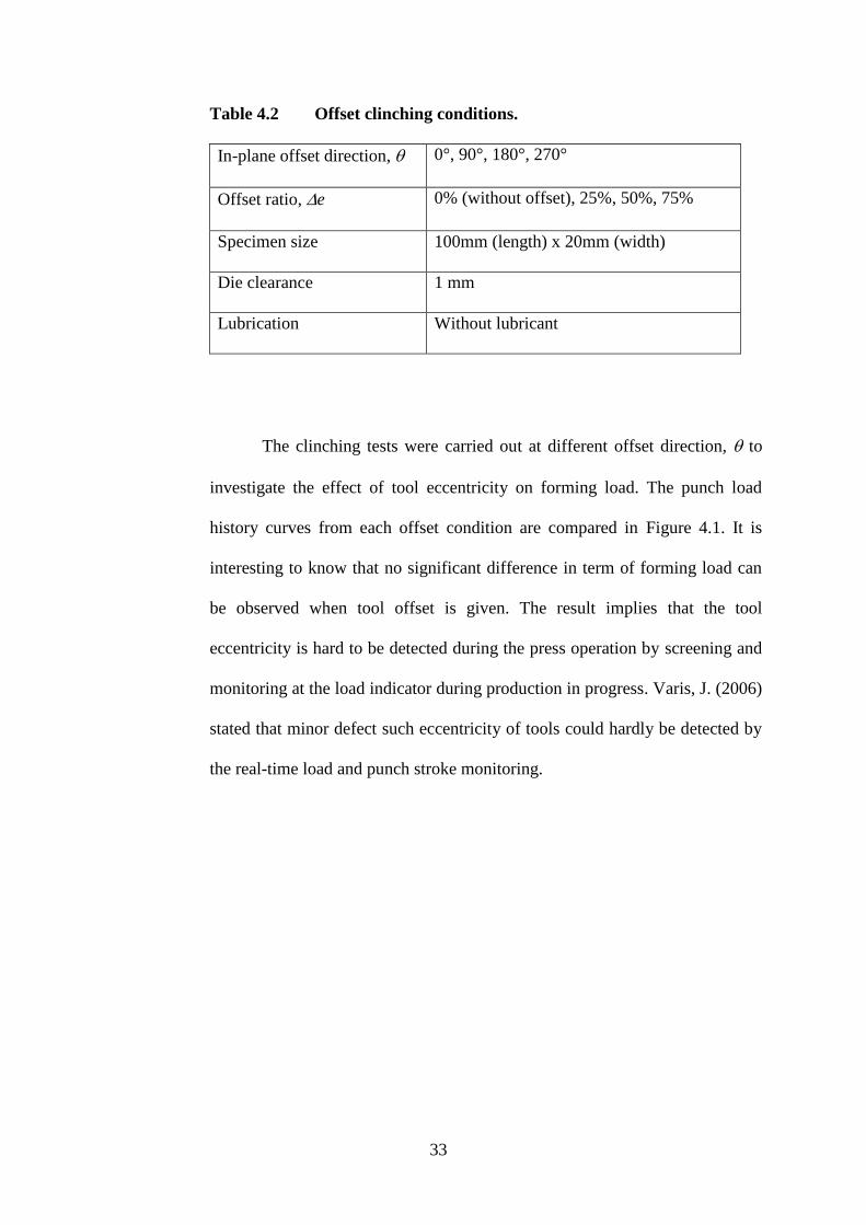
Table 4.2 Offset clinching conditions.
In-plane offset direction, 0°, 90°, 180°, 270°
Offset ratio, e 0% (without offset), 25%, 50%, 75%
Specimen size 100mm (length) x 20mm (width)
Die clearance 1 mm
Lubrication Without lubricant
The clinching tests were carried out at different offset direction, to
investigate the effect of tool eccentricity on forming load. The punch load
history curves from each offset condition are compared in Figure 4.1. It is
interesting to know that no significant difference in term of forming load can
be observed when tool offset is given. The result implies that the tool
eccentricity is hard to be detected during the press operation by screening and
monitoring at the load indicator during production in progress. Varis, J. (2006)
stated that minor defect such eccentricity of tools could hardly be detected by
the real-time load and punch stroke monitoring.

34
Figure 4.1: Comparison of punch load curves with different offset
direction, θ (e = 50%, rb = 60%, coated mild steel).
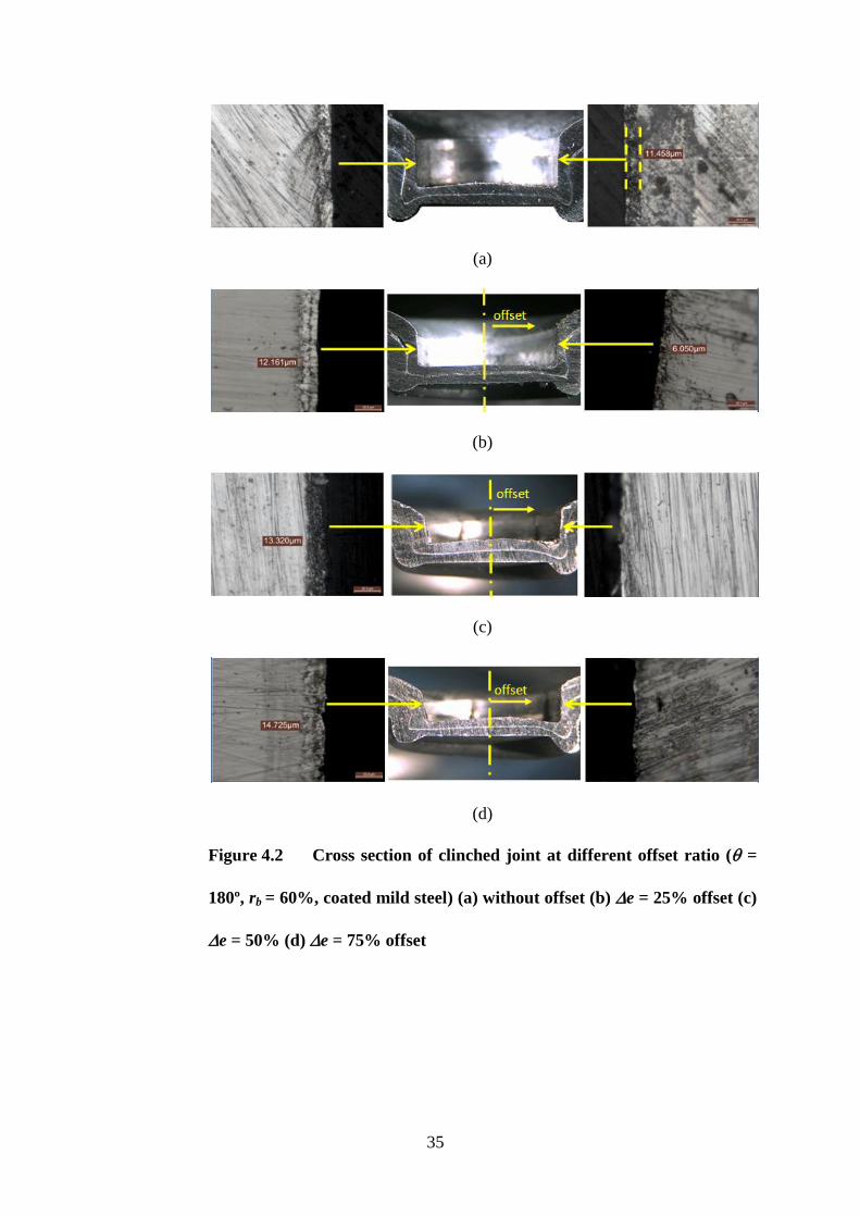
Figure 4.2 shows the cross section of clinched joint where interlock, ts,
neck thickness, tn and coated layer at the left and right side of clinched
specimens are examined with respect to the offset ratio, e. The punch is
offset to = 180 direction (moved to the right) to form smaller die clearance
on right side. The extruded part (ear shape) at the bottom side can be seen
larger on the right side and uneven ear shapes appear at both corners when
offset the ratio, e is given larger than 50%. The results from examining the
cross section are compared in Figure 4.3.
0
10
20
30
40
50
60
70
0 0.5 1 1.5 2 2.5 3
Punch
load
(kN
)
Punch stroke (mm)
Without offset
= 0°, 180°
= 90°, 270°
Force & Stroke
Sensor
35
(a)
(b)
(c)
(d)
Figure 4.2 Cross section of clinched joint at different offset ratio ( =
180º, rb = 60%, coated mild steel) (a) without offset (b) e = 25% offset (c)
e = 50% (d) e = 75% offset

36
Figure 4.2 (b), (c) and (d) show the distribution of the neck thickness,
interlock and the protruding part at the bottom were unevenly formed when
compare to the without offset as shown in Figure 4.2 (a). Figure 4.2 (b), (c)
and (d) also show some similarity to Figure 1.4. The tooling eccentricity
influenced the material flow while forming. The dimension of clinch interlock,
ts and neck thickness, tn were skewed to one side. The distribution of clinch
interlock, ts and neck thickness, tn were not uniform around the clinch joint as
shown in Figure 4.2 (b), (c) and (d). These two parameters are critical to the
joint strength.
Figure 4.3(a) shows the interlock, ts value increases on the right side
while it decreases on the left side along with increment of offset ratio, e. The
different is almost 20% at offset ratio, e = 75% in respect to the one without
offset. This result implies that the pull-out strength (in opening mode) on the
left side is higher while it is lower on the right side.
Figure 4.3 (b) shows that the neck thickness, tn decreases on the right
side due to smaller die clearance given while it increases on the left side along
with the increment of offset ratio, e. The different is almost 15% at offset
ratio, e = 75% in respect to the one without offset. The thinning occurred at
the neck part may easily induce neck failure when loading point is placed on
right side.
The coated layer is examined by microscope at the neck part of upper
layer since this location is most critical to cause neck failure due to large

37
stretching. Figure 4.3 (c) shows a drastic reduction of the coated layer on the
right side when offset ratio, e is increased to 50%, while the value on the left
side remains intact as its original thickness. The coated layer appeared to be
peeled off completely due to severe condition of plastic deformation and
surface friction takes place when material is stretched through the narrow die
clearance. The neck thickness, tn, interlock, ts and coating layer varies around
the clinched joint is due to the alteration of tooling geometry that is caused by
tooling eccentricity (Varis,J.P..2003, Abe et al. 2008, Abe et al. 2012).
(a)
0
0.1
0.2
0.3
0.4
0.5
0% 25% 50% 75%
Inte
rlock
ts (
mm
)
Offset ratio e (%)
Without offset
Lef
t
Right

38
(b)
(c)
Figure 4.3 Comparison of thickness parameter between left and right
side of offset clinched joints ( = 180º, rb = 60%, coated mild steel) (a)
interlock, ts (b) neck thickness, tn (c) coated layer
0
0.1
0.2
0.3
0.4
0.5
0% 25% 50% 75%
Nec
k t
n (
mm
)
Offset ratio e (%)
Without offset
Left Right
0
2
4
6
8
10
12
14
16
0% 25% 50% 75%
Coat
ed l
ayer
(
m)
Offset ratio e (%)
Without offset
Left Right
39
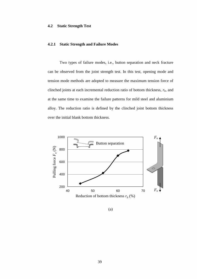
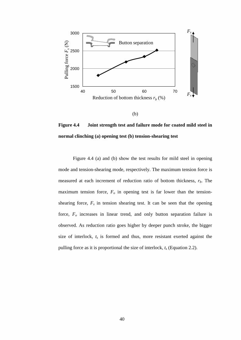
4.2 Static Strength Test
4.2.1 Static Strength and Failure Modes
Two types of failure modes, i.e., button separation and neck fracture
can be observed from the joint strength test. In this test, opening mode and
tension mode methods are adopted to measure the maximum tension force of
clinched joints at each incremental reduction ratio of bottom thickness, rb, and
at the same time to examine the failure patterns for mild steel and aluminium
alloy. The reduction ratio is defined by the clinched joint bottom thickness
over the initial blank bottom thickness.
(a)
200
400
600
800
1000
40 50 60 70
Pull
ing f
orc
e F
o (
N)
Reduction of bottom thickness rb (%)
Button separation
Fo
Fo
40
(b)
Figure 4.4 Joint strength test and failure mode for coated mild steel in
normal clinching (a) opening test (b) tension-shearing test
Figure 4.4 (a) and (b) show the test results for mild steel in opening
mode and tension-shearing mode, respectively. The maximum tension force is
measured at each increment of reduction ratio of bottom thickness, rb. The
maximum tension force, Fo in opening test is far lower than the tension-
shearing force, Fs in tension shearing test. It can be seen that the opening
force, Fo increases in linear trend, and only button separation failure is
observed. As reduction ratio goes higher by deeper punch stroke, the bigger
size of interlock, ts is formed and thus, more resistant exerted against the
pulling force as it is proportional the size of interlock, ts (Equation 2.2).
1500
2000
2500
3000
40 50 60 70
Pull
ing f
orc
e F
s (N
)
Reduction of bottom thickness rb (%)
Button separation
Fs
Fs
41
(a)
(b)
Figure 4.5 Joint strength test and failure mode for aluminium alloy in
normal clinching (a) opening test (b) tension-shearing test
Similar tests are carried out for aluminium alloy, and the results are
plotted in Figure 4.5 (a) and (b). The failure starts from button separation with
the force value of opening force, Fo and shearing force, Fs increased. As the
reduction ratio goes about 40%, the failure mode shifts from button separation
to neck fracture pattern when the opening force, Fo and tension-shearing force,
Fs reach maximum and become constant. The neck fracture is prevailed in
0
50
100
150
200
0 10 20 30 40 50 60 70 80
Pull
ing f
orc
e F
o (
N)
Reduction of bottom thickness rb (%)
Button separation
Neck fracture
0
250
500
750
1000
0 10 20 30 40 50 60 70 80
Pull
ing f
orc
e F
s (N
)
Reduction of bottom thickness rb (%)
Button
separation
Neck fracture
Fo
Fo
Fs
Fs
42
later stage because the stress level at the neck part may have reached the
ultimate point of tensile stress (Equation 2.1).
4.2.2 Static Strength Test for Offset Clinching
According to J.Mucha (2011), when a pair of pulling force is applied to
the structure, the internal forces will appeared on the layer boundary and react
at one side of the corner as illustrated in Figure 4.6. In view of this, it can be
assumed that the joint strength will exhibit significant changes for the case of
offset clinching where interlock, ts and neck thickness, tn of the joint are found
varied with respect to offset direction and offset ratio (see Figure 4.3). Thus,
the opening test and tension-shearing test are carried out in this study to
examine the joint strength behaviour caused by the offset clinching
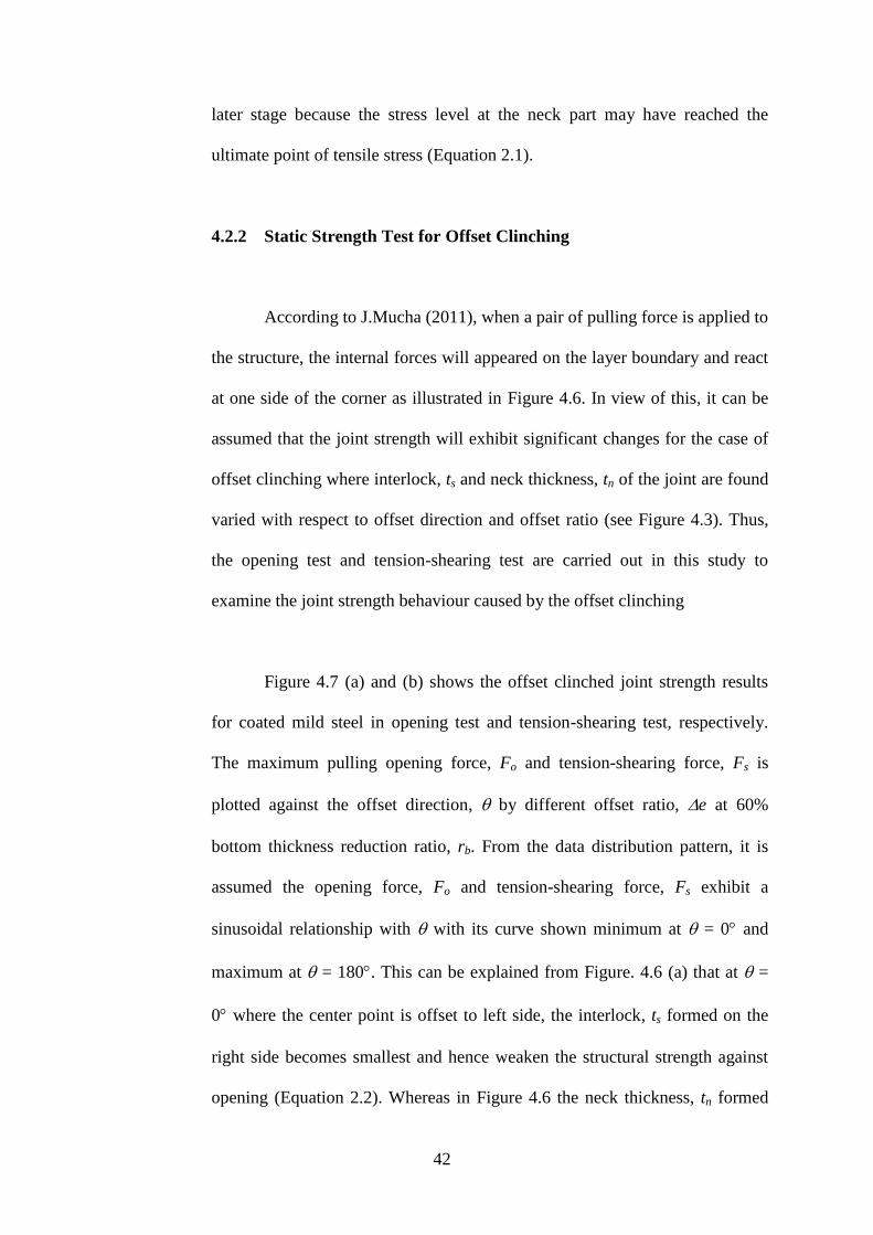
Figure 4.7 (a) and (b) shows the offset clinched joint strength results
for coated mild steel in opening test and tension-shearing test, respectively.
The maximum pulling opening force, Fo and tension-shearing force, Fs is
plotted against the offset direction, by different offset ratio, e at 60%
bottom thickness reduction ratio, rb. From the data distribution pattern, it is
assumed the opening force, Fo and tension-shearing force, Fs exhibit a
sinusoidal relationship with with its curve shown minimum at = 0 and
maximum at = 180. This can be explained from Figure. 4.6 (a) that at =
0 where the center point is offset to left side, the interlock, ts formed on the
right side becomes smallest and hence weaken the structural strength against
opening (Equation 2.2). Whereas in Figure 4.6 the neck thickness, tn formed

43
on the left side becomes thinnest and hence weakened the structural strength
against shearing. The situation is reversed at = 180 with the strength turns
to maximum with larger interlock, ts on the right side and larger neck
thickness, tn on the left side.
(a)
(b)
Figure 4.6 Illustration of internal force interactions at the layer
boundary of clinched joint (a) opening test (b) tension-shearing test
Offset e
Fs
Fs
Internal forces
Fo
e Offset Fo

44
(a)
(b)
Figure 4.7 Joint strength tests at different offset conditions for coated
mild steel (reduction of bottom thickness, rb = 60%) (a) opening test (b)
tension-shearing test
In the opening test shown in Figure 4.7 (a), the strength curves by
offset clinching is generally lower than the one without offset and further
reduced by the higher offset ratio, e. However, it is interesting to see that
offset strength curves shown in Figure 4.7 (b) behave in opposite trend in
tension-shearing test. The phenomenon may be due to the strain hardening
300
400
500
600
700
800
0 90 180 270
Pu
llin
g F
orc
e F
o (
N)
Punch offset orientation (º)
e = 0%
e = 25%
e = 50%
e = 75%
Without offset
2200
2400
2600
2800
0 90 180 270
Pull
ing F
orc
e F
o (
N)
Punch offset orientation (º)
e = 0%
e = 25% e = 50%
e = 75%
Without offset
Fo
Fo
Fs
Fs
45
effect takes place at the neck part for mild steel material and thus exhibits
higher resistance against shearing than the one without offset.
(a)
(b)
Figure 4.8 Joint strength tests at different offset conditions for
aluminium alloy (reduction of bottom thickness, rb = 60%) (a) opening test
(b) tension-shearing test
0
50
100
150
200
250
300
0 90 180 270
Pu
llin
g F
orc
e F
o (
N)
Punch offset orientation (º)
e = 0%
e = 25% e = 50%
e = 75%
Without offset
550
600
650
700
750
0 90 180 270
Pull
ing F
orc
e F
s (N
)
Punch offset orientation (º)
e = 25%
e = 0%
e = 25%
e = 50%
e = 75%
Without offset
Fo
Fo
Fs
Fs

46
For the case of aluminium alloy in Figure 4.8 (a), although the joint
strength show similar curve pattern with the one of coated mild steel in
opening test, however, the values drop drastically when compared at the same
level of offset ratio, e.g., at e = 50%. This is because the neck failure
occurred at neck part of aluminium alloy, whereas only button separation
failure for coated mild steel (see Figure 4.5 (a) and (b) ).
In the case of tension-shearing test for aluminium alloy, the offset
strength curve shown in Figure 4.8 (b) is lower than the one without offset.
The phenomenon is opposed to the case of coated mild steel where it shows
higher strength in Figure 4.7 (b). This may due to the neck failure occurred at
the neck part for aluminium alloy.
4.3 Fatigue Strength Test
Figure 4.9 shows the comparison of fatigue test result in tension-
shearing mode for coated mild steel clinched joint of condition e = 0%, =
0 and e = 50%, = 0 for coated mild steel sheet metal. At 50% of
maximum joint strength, the clinched joint of without offset completed the
fatigue test at 2 x 10⁷ number of cycles. This result agree with the finding of
Carboni et al. (2006) that concluded the endurance limit of a clinched joint of
without offset is 50% of the shearing load. On the other hand, at 50% of
maximum joint strength, the clinched joint of e = 50% failed at 2.5 x 10⁶
number of cycles. It shows a difference of 87.5% by number of cycles when

47
comparing a clinch joint of without offset and e = 50%..The clinched joint of
e = 50% completed the test at 42.5% maximum joint strength in order to
achieve 2 x 10⁷ number of cycles. The fatigue strength of a clinched joint is
weaken due to the tooling eccentricity.
\
Figure 4.9 Relationship between percentage of joint strength and
number of cycles in fatigue tension-shearing test for coated mild steel
(reduction of bottom thickness, rb = 60%).
4.4 Finite Element Simulation for Offset Clinching
Comparisons are made to examine the effectiveness of simulated
results by present 2D rigid-plastic FEM model on forming load and the cross
section of clinched joint in offset and without offset cases. The flow stress
shown in Table 4.1 and the Coulomb’s friction coefficient of 0.2 (Abe et al,
2008) between tools and blank are used for perform the FEM analysis.
0
20
40
60
80
100
1.E+00 1.E+02 1.E+04 1.E+06 1.E+08
Join
t st
ren
gth
per
cen
tage
(%)
Number of cycle (N)
Endurance limit:
2 x 10⁷ cycles
e=0%
e=50%

48
Figure 4.10 Comparison of punch load between experimental and
simulated results (reduction of bottom thickness, rb = 60%, coated mild
steel).
Despite a simplified 2D model is introduced, Figure 4.10 and Figure
4.11 (a) shows a fairly closed agreement between the experimental and
simulated in terms of forming load curve and cross section profile in
clinching. Figure 4.11 (b) shows the present FEM simulation is able to predict
the formation of interlock, ts and the simulated result shows closed agreement
with the experimental results.
0
10
20
30
40
50
60
0 0.5 1 1.5 2 2.5
Punch
Load
(kN
)
Punch Stroke (mm)
Experiment
Axi-symmetric FEM
Plane-strain FEM
49
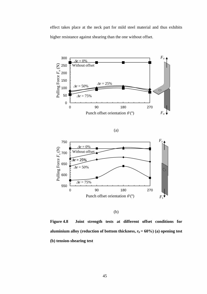
(a)
(b)
Figure 4.11 Comparison of cross section and formation of interlock
between experimental and simulated results (a) cross section (b) interlock
0
0.05
0.1
0.15
0.2
0.25
0 20 40 60 80
Inte
rlock
ts
(mm
)
Reduction of Bottom Thickness rb (%)
Experiment
Simulation
0.49mm
0.22mm 0.22mm
0.48mm
50
(a)
(b)
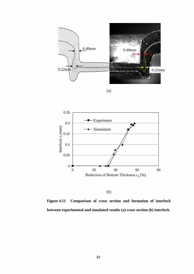
Figure 4.12 Offset clinching simulation by FEM in plain-strain model
(a) experiment result (b) simulation result
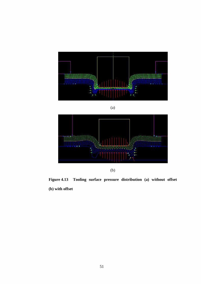
From Figure 4.12, it is perhaps a plane-strain model can be used as the
first attempt of approximation to study the physical phenomenon in offset
clinching. From the offset simulation, it is found that the peak value of tool
contact pressure distribution is shifted off from the center axis (see Figure
4.13). This implies an unintended eccentric force exerted on the punch and the
peak value can increase up to 12% at e = 75% although the total forming
load shows no significant different between the one of without offset and with
offset (see Figure 4.14).
offset
51
(a)
(b)
Figure 4.13 Tooling surface pressure distribution (a) without offset
(b) with offset

52
Figure 4.14 Effect of tooling eccentricity to the punch localized
maximum pressure
Figure 4.15 Cracked punch
As a result of increasing in local maximum pressure, the punch cracked
before achieving the expected tool service lifespan.
1.5
1.6
1.7
1.8
1.9
2.0
0 20 40 60 80
Conta
ct P
ress
ure
(G
Pa)
Offset Ratio e (%)

53
CHAPTER 5
CONCLUSION AND FUTURE WORKS
5.1 Conclusions
In this study, the alignment of the punch and die is purposely offset in
order to study the effect of tool eccentricity in mechanical clinching to the
strength of clinched joint. Two parameters were introduced, i.e. the in-plane
offset direction, and offset ratio, e to define the orientation and intensity of
the offset condition in the misalignment of the tooling. Opening test and
tension-shearing test were carried out to evaluate the joint strength.
The punch load curves shows little difference when a joint is clinched
under the condition of without offset and with offset even up to offset ratio, e
of 75%. However, in the study of the cross section of an offset clinched joint,
the value of interlock, ts and neck thickness, tn varies at different positions
around the round clinched joint due to the non-symmetrical deformation.
The coating layer at the neck part is completely peeled off at 50%
offset ratio due to the sheet metal is stretched through a smaller die clearance
on one side because of tool eccentricity.
54
The strength of a clinched joint is considered to have achieved
maximum level once neck failure mode takes place. Greater reduction of
bottom thickness, rb. will be futile in increasing the joint strength.
In the opening test and tension-shearing test, the maximum pulling
force of the offset clinched joint fluctuates in sinusoidal relationship with
respect to the offset direction, and offset ratio, e.
The intensity of offset ratio,e and offset direction, together alter the
pulling force of a clinched joint. In the opening test, the tool eccentricity of
25% to 75% causes in a decrease in joint strength by a range of 60-70% for
aluminium alloy and 0-43% for mild steel. While in the tension-shearing test,
the joint strength is reduced by 0-20% for aluminium alloy. However, there is
a special phenomenon in the tension-shearing test of mild steel where the joint
strength is increased by 2-18%, this may be caused by strain-hardening effect.
In the tension-shearing fatigue test, the fatigue strength of a clinched
joint with offset condition of = 0 and e = 50% is generally 5-10% weaker
to a clinched joint without offset.
The use of 2D rigid-plastic FEM as simulation tool is considered
sufficient as the first attempt of approximation to investigate the sensibility of
design parameters such as offset parameters and the use of different materials.
It is predicted that the peak value of tool contact pressure distribution is
shifted off from the center axis in offset clinching simulation. This implies that

55
an unintended eccentric force exerted on the punch and the peak value can
increase up to 12% at e = 75% although the total forming load shows no
significant difference with the one without offset. This effect shortens the
lifespan of tools.
The tolerance of the tool eccentricity should be limited to e = 25%
and offset direction of = 180 in order to acquire the expected quality of
clinched joint and preserve tool service lifespan. Cross section of a clinched
joint shall be evaluated to investigate the alignment of the clinching tools.
Tools shall be replaced or reconfigure if the neck thickness, tn and interlock, ts
deviate more e = 25% and offset direction of = 180.
5.2 Future Works
Although the effect of eccentricity is investigated, more experiments
maybe needed in the eccentricity range less than 25% for industrial use. In
current work, the study of tool eccentricity effect is focused more on the static
strength of a mechanical clinching joint. Therefore, more fatigue testing at
different degree of offset and offset direction should be tested in order to have
a better understanding about the effect of tool eccentricity to the dynamic
strength of a mechanical clinching joint.
In this research, 2D FEM model was applied to study on the effect of
tool eccentricity on clinched joint. Therefore, future research can be conducted
to study the effect by using 3D FEM model to provide a more accurate result

56
for the explanation to be accepted about the occurance of neck fracture failure
caused by the lower strain hardening effect at the interlock part in case of
aluminium over to the steel.

57
REFERENCES
Abe, Y., Kato, T., Mori, K., 2007. Joining of aluminium alloy and mild steel
sheets using mechanical clinching. Materials Science Forum 561-565, pp.
1043-1046.
Abe, Y., Matsuda, A., Kato, T., Mori, K., 2008. Plastic joining of aluminium
alloy and high strength steel sheets by mechanical clinching. Special research
int. 79(2008), Special Edition Metal Forming Conference 2008, Volume 1.
Abe, Y., Kato, T., Mori, K., 2011. Joining of aluminium alloy sheets by
rectangular mechanical clinching. The 14th International ESAFORM
Conference on Material Forming AIP Conf. Proc. 1353, pp. 1253-1258.
Abe, Y., Mori, K., Kato, T., 2012. Joining of high strength steel and
aluminium alloy sheets by mechanical clinching with dies for control of metal
flow. Journal of Materials Processing Technology 212 (4), pp. 884–889.
Ali, M.S., 2005. A support system for evaluating a suitable joining method in
the production of sheet metal goods. Lappeenranta University of Technology,
Finland.

58
Altan,T., Boulger, F.W., 1973. Flow stress of metals and its application in
metal forming analyses, Trans. ASME, J.Eng. Ind., p1009
Balawender, T., Sadowski, T., Knec, M., 2011. Technological problems and
experimental investigation of hybrid: clinched- adhesively bonded joint,
Archives of Metallurgy and Materials, 56(2), pp. 439-446.
Bellini, P., Bruno, I., Nesi, P., 2004. A distributed system for computer vision
quality control on clinched boards. Journal on Real-Time Imaging, 10(3), pp.
161-176.
Chan-Joo Lee, J.-Y.K., Dae-Cheol Ko, Byung-Min Kim., 2009. Design of
mechanical clinching tools for joining of aluminium alloy sheets. Materials
and Design 31, pp. 1854-1861.
Coppieters, S., Cooreman, S., Lava, P., Sol, H., Van Houtte, P., Debruyne, D.,
2010. Reproducing the experimental pull-out and shear strength of clinched
sheet metal connections using FEA, International Journal of Material
Forming 4(4), pp 429-440.

59
Coppieters, S., Lava, P., Baes, S., Sol, H., Van Houtte, P., Debruyne, D., 2011.
Analytical method to predict the pull-out strength of clinched connections.
Thin-Walled Structures 52, pp. 42-52.
Dingfield, G., 2008. Eckold brought mechanical joining technology to market
perfection 25 years of clinching technology- development of a new technique.
Eckold GmbH & Co. KG, pp 1-6.
Lee, C.J., Kim, J.Y., Lee, S.K., Ko, D.C., Kim, B.M., 2010. Design of
mechanical clinching tools for joining of aluminium alloy sheets. Materials
and Design 31, pp. 1854–1861.
Mori, K., Osakada, K., Oda, T., 1982. Simulation of plane-strain rolling by the
rigid-plastic finite element method. International Journal of Mechanical
Sciences 24, pp. 519-527.
Mori,K., Wang, C.C., Osakada, K., 1994. Analysis of plate and sheet forming
process by combination of elastic & rigid-plastic fem. Japan Society of
Mechanical Engineers Series C, 60(573), p.96

60
Mori,K., Wang, C.C., Osakada, K., 1995. Controlled FEM simulation for
determining history of blank holding force in deep drawing. CIRP Annals-
Manufacturing Technology, 44(1), pp. 243-246.
Mori,K., Wang, C.C., Osakada, K., 1996. Inclusion of elastic deformation in
rigid-plastic finite element analysis. International Journal of Mechanical
Sciences, 38(6), pp. 621-631.
Mori, K., Abe, Y., Kato, T., 2012. Mechanism of superiority of fatigue
strength for aluminium alloy sheets joined by mechanical clinching and self-
pierce riveting. Journal of Materials Processing Technology 212, pp. 1900–
1905.
Mucha, J., 2011. The analysis of rectangular clinching joint in the shearing
test. Maintenance and Reliability NR, 3(51), pp. 45-50.
Mucha, J., 2011. The analysis of lock forming mechanism in the clinching
joint. Materials and Design 32, pp. 4943 – 4954.
61
Mucha, J., Kascak, L., Spisak, E., 2011. Joining the car-body sheets using
clinching process with various thickness and mechanical property
arrangements. Archives of Civil and Mechanical Engineering 11(1), pp.135-
148.
NongN. K.O., Yu Z., Zhiyuan Q., Changcheng T., Feipeng L., 2003. Research
on press joining technology for automotive metallic sheets. Journal of
Material Processing Technology, 137(1-3), pp.159-163.
Osakada, K., Nakano, J., Mori, K., 1982. Finite element method for rigid-
plastic analysis of metal forming-formulation for finite deformation.
International Journal of Mechanical Sciences 24, pp. 459-468.
Oudjene, M., Ben-Ayed, L., 2008. On the parametrical study of clinch joining
of metallic sheets using the taguchi method. Engineering Structures 30, pp.
1782-1788.
Varis, J.P., 2003. The suitability of clinching as a joining method for high-
strength structural steel. Journal of Materials Processing Technology 132, pp.
242-249.
62
Varis, J.P., Lepistö, J., 2003. A simple testing-based procedure and simulation
of the clinching process using finite element analysis for establishing clinching
parameters. Thin-Walled Structures 41, pp. 691–709.
Varis, J., 2006. Ensure the integrity in clinching process. Journal of Materials
Processing Technology, 174, pp. 277-785.
Wang, C.C., Mori, K., Osakada. K., 1995. A simple method for measuring
flow stress of metal plate by u-shape bending. Japan Society of Mechanical
Engineers Series C, 61(590), p. 4094.
Wang, C.C., 2008. Finite element simulation for forging process using euler’s
fixed meshing method. Materials Science Forum, 720(575), pp. 1139-1144.
Wang, C.C., 2009. Development of finite element simulator for forging
process design using euler’s fixed meshing method. International Journal of
Precision Technology 1(2), PP. 173-182.

63
APPENDIX A
TENSILE TEST RESULT
Figure A1: Stress-strain curve of aluminium alloy A1100 H14
Figure A2: Stress-strain curve of coated mild steel GL400 FN AZ150
64
APPENDIX B
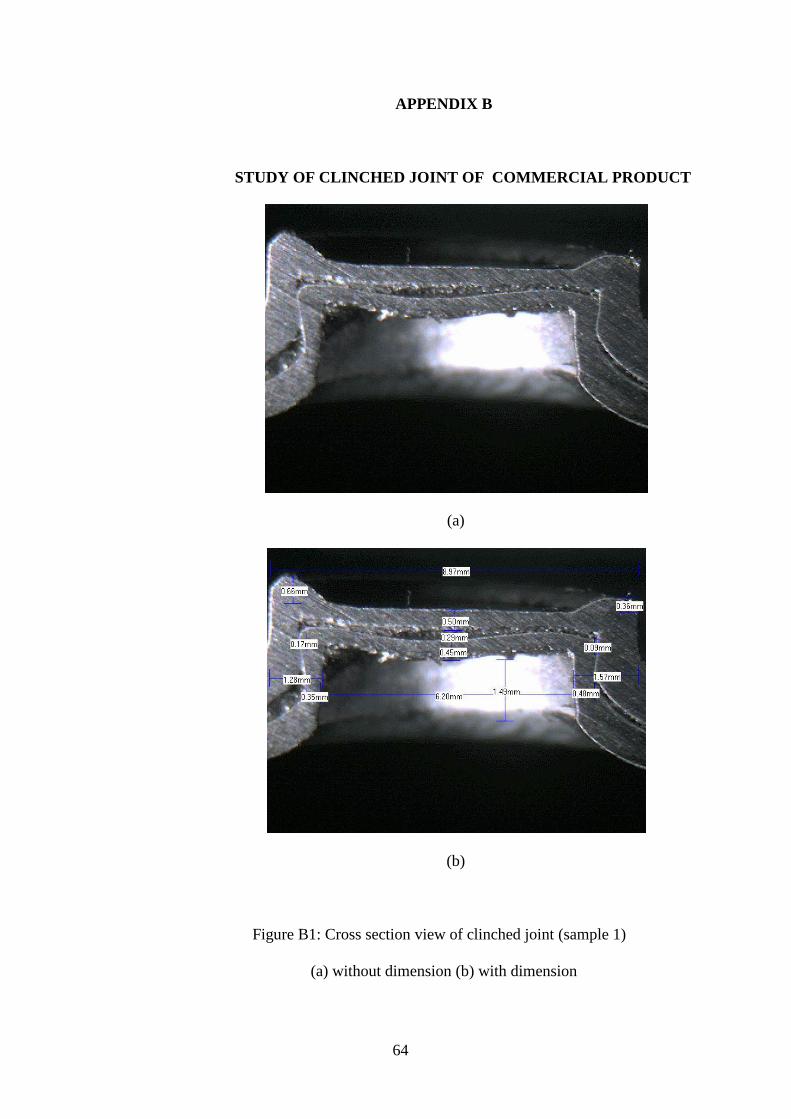
STUDY OF CLINCHED JOINT OF COMMERCIAL PRODUCT
(a)
(b)
Figure B1: Cross section view of clinched joint (sample 1)
(a) without dimension (b) with dimension

65
(a)
(b)
Figure B2: Cross section view of clinched joint (sample 2)
(a) without dimension (b) with dimension

66
APPENDIX C
EXPERIMENT APPARATUS
Figure C1: Die set
Figure C2: Punch and die
67
APPENDIX D
LIST OF PUBLICATION
1.0 Journal Paper
Cheong, W.C., Kam, H.K., Wang, C.C., Lim, Y.P., 2013. Study of
cold rotary forming by using rigid-plastic finite element method.
Advanced Materials Research 626, pp. 662-666.
Cheong, W.C., Kam, H.K., Wang, C.C., Lim, Y.P., 2014. Rigid-plastic
finite element simulation of cold forging and sheet metal forming by
eulerian meshing method. Advanced Material Research 970, pp. 177-
184.
Kam, H.K., Cheong, W.C., Wang, C.C., 2013. Development of
lubricants evaluation for different friction laws by using rigid-plastic
finite element method. Advanced Materials Research 626, pp 584-588.
Kam, H.K., Cheong, W.C., Wang, C.C., 2014. Effect of tool
eccentricity on the joint strength in mechanical clinching process.
Material Research Innovation, Accepted (Thomsom ISI indexed
journal).
68
2.0 Conference Paper
Cheong, W.C., Kam, H.K., Wang, C.C., Lim, Y.P., 2012. Application
of rigid-plastic finite element method using euler’s fixed meshing
method for cold forging. 2nd
Annual International Conference on
Material Science, Metal & Manufacturing (M3 2012), pp.92-97.
Kam, H.K., Cheong, W.C., Wang, C.C., 2012. Effect of tools
eccentricity to the pull-out strength in sheet metal clinching process.
2nd
Annual International Conference on Material Science, Metal &
Manufacturing (M3 2012), pp. 57-62.
Kam, H.K., Cheong, W.C., Wang, C.C., 2014. Effect of tool
eccentricity on the joint strength in mechanical clinching process. 11th
Iinternational Conference on Technology of Plasticity, 2014, Accepted