an evolution friendly modular architecture to produce
TRANSCRIPT
Robotics and Autonomous Systems 63 (2015) 195–205
Contents lists available at ScienceDirect
Robotics and Autonomous Systems
journal homepage: www.elsevier.com/locate/robot
An evolution friendly modular architecture to produce feasible robotsA. Faiña a, F. Bellas b,∗, F. Orjales b, D. Souto b, R.J. Duro b
a IT University of Copenhagen, Denmarkb Integrated Group for Engineering Research, Universidade da Coruña, Spain
h i g h l i g h t s
• We present a modular architecture to produce feasible robots through evolution.• The architecture is based on a set of a heterogeneous modules.• The modules contain a large number of connection faces per module.• The design and the implementation of prototype modules is described in detail.• Different experiments show its potential for evolving robot morphologies and control.
a r t i c l e i n f o
Article history:Available online 7 August 2014
Keywords:Modular robotsEvolutionary designEvolvability
a b s t r a c t
This paper proposes the use of a modular robotic architecture in order to produce feasible robots throughevolution. To this end, the main requirements the architecture must fulfill are analyzed and a top-downmethodology is employed to obtain the different types of modules that make it up. Specifically, the prob-lem of how to increase the evolvability or evolution friendliness of the system is addressed by consideringa heterogeneous modular architecture with a large number of connection faces per module. Afterwards,a prototypical implementation of these modules with the required features is described and different ex-periments provide an indication of how versatile the architecture is for evolving robot morphologies andcontrol for specific tasks and how easy it is to build them.
© 2014 Elsevier B.V. All rights reserved.
1. Introduction
Designing a robot for a specific task and environment is a com-plex process that relies heavily on the expertise of designers. Itusually involves two isolated steps where the morphology of therobot is first selected according to the environment and task fea-tures and, afterwards, the controller is programmed. These twoisolated phases for designing the morphology of the robot and itsbehavior do not exploit the fact that morphology, controller, andenvironment are highly interdependent. In fact, several authorshave pointed out that embodiment is a key aspect for developingreally intelligent robots [1,2]. Complex, robust, and well adaptedbehaviors can be obtained with simpler controllers by exploitingthe ‘‘morphological intelligence’’ of the robots [3–5].
One of the main approaches to address this complex designprocess is based on evolution. In fact, in the last three decades,
∗ Correspondence to: Escuela Politécnica Superior, Universidade da Coruña,Mendizábal s/n, 15403 Ferrol (A Coruña), Spain. Tel.: +34 981 337400x3886; fax:+34 981 337410.
E-mail addresses: [email protected] (A. Faiña), [email protected], [email protected],[email protected] (F. Bellas), [email protected] (F. Orjales),[email protected] (D. Souto), [email protected] (R.J. Duro).
http://dx.doi.org/10.1016/j.robot.2014.07.0140921-8890/© 2014 Elsevier B.V. All rights reserved.
several examples can be found where evolutionary algorithmshave been successfully employed to design controllers for robots.On one hand, some authors have resorted to fixed morpholo-gies [6–8]. These embodiment approaches use the interrelationsbetween the morphology of the robot and its environment to finda suitable controller which provides the desired behavior. On theother hand, in order to automate thewhole robot designprocess fora task and environment, some authors have introduced the mor-phology of the robot as part of the search space and they simulta-neously co-evolve morphology and control. As commented above,the main advantage of this approach is that it exploits the interre-lations between the morphology, the control and the environmentfor a specific task.
Following this second approach, authors such as Sims, in theirseminal work, coevolved the morphology and the control of vir-tual creatures for tasks such as walking, swimming or jumping [9].His work was based on cubic bodies joined by hinges, neural net-works as a control system and a generative encoding. After hiswork, other authors have coevolved robots for different tasks in asimilar way [10–12]. Nevertheless, these approaches only producevirtual creatures that cannot be transferred to reality without anad hoc adaptation. Furthermore, as the algorithms do not take into
196 A. Faiña et al. / Robotics and Autonomous Systems 63 (2015) 195–205
account any physical constraint, most of the solutions are unfeasi-ble. For example,most of these approaches employ jointswith hightorque motors, very light weight structures and dynamic enginesconfigured to achieve fast evaluations, but with low accuracy.
Other authors have studied how to achieve feasiblemorpholog-ical designs automatically. To this end, one interesting approachwas employed in the Golem project [13]. Here, the morphologi-cal shape and the control parameters of virtual structures basedon bars (some of them with telescopic actuators) and ball–socketjoints were coevolved. Afterwards, some selected morphologieswere processed by an algorithm to obtain feasible designs whichcould be built using a 3D printer. Aftermanually removing the sup-port material and installing the motors, these robots were able tooperate using an external control structure. More recently, Cheneyet al. [14] have coevolved soft robots using generative encodings.These robots can be built using an ad hoc process and they can beactuated varying the external pressure [15].
A different approach to automatically obtain feasible robots isto make use of some kind of blocks as a basic set of elementarybuilding parts for the morphological evolution. This approach im-plies a discrete search space, but it guarantees that all solutions canbe built. In this line, some authors employ Lego bricks as the ba-sic element for morphological construction. A point in case is [16],which is more focused on morphology than on control or, morerecently [17], that employs three different types of parts (a hingejoint, a controller block and several Lego bricks) for evolving therobots. Apart from Lego bricks [18], proposed using bars and cir-cular sockets (actuated or fixed) as basic elements to design robotsusing a generative encoding based on Lindenmayer systems.
The main drawback of these approaches is that, although therobots they produce are feasible and can be built, they are only aproof of concept to show that coevolution can achieve successfulrobots for simple tasks like locomotion on flat surfaces in labo-ratory environments. Furthermore, most of the robots need a la-borious building process to obtain the desired morphologies and,obviously, Lego bricks are not a suitable architecture to generateuseful robots in any real industrial environment.
This paper shares with the previous approach its use of prede-fined blocks, but with a different perspective. The work presentedhere is based on robotic modules, which allow us to quickly de-ploy useful modular robots for complex tasks and environments.Modular robots are built by joining some relatively simple devicescalledmodules. They are autonomous deviceswith a few actuators,sensors, communications, and some computational capabilities.Complex robots with different morphologies can be created bycombining a small set of predesigned modules. There are a lot ofdifferent modular architectures that have shown high versatilityfor building different morphologies [19–23]. The use of modularrobots to coevolve the morphology and control guarantees thatall the solutions obtained are feasible and they make building therobots easier and faster. Nevertheless, compared to using simpleblocks such as Lego parts, the new search space these modulesinduce makes evolution harder due to the increased deceptive-ness. Evolution is still discrete but its resolution is decreased as theblocks are larger. Consequently, the addition or deletion of one ofthe modules generates more pronounced changes in the behaviorof the robot.
The first attempts to design modular robots tried to obtain theconfiguration by only evaluating the morphological features ofserial manipulators [24–26]. That is, the controller and dynamicproperties of the systemwere not taken into account and were re-placed by an analysis of the kinematics of the system. Similarly,Farritor and Dubowsky [27] explored this approach to developrobots for industrial tasks based on a kinematic analysis and a setof features of the task like, for example, the tallest obstacle thatthe robot had to go over. Leger [28] resorted to kinematic and dy-namic analyses to generate field robots based on a base element
with several serial manipulators, where the paths for the end ef-fectors of the manipulator were predefined as a part of the task.Similar to this work, Chocron coevolved modular robots for roughexplorations using dynamic simulators [29].
Despite the fact that all of these approaches generate feasiblerobots, they are mostly based on simulated modular architecturesand they lack a physical implementation. Only a few authors haveexperimented with designing modular robots using real modulararchitectures. In this line, Lund coevolved themorphology and con-trol of line-follower robots based on modules built using assem-blies of Lego parts [30] (in this case they use modules with sensingand acting capabilities, and not only Lego blocks). Also, Marbachand Ijspeert coevolved simulated virtual robots using central pat-tern generators and Yamormodules, an homogeneous architecturebased on hinge joints [31].
While simulated robotic modular architectures present inter-esting properties in order to increase their versatility, and in somecases, even their evolvability, real implemented modular architec-tures generally lack these features. In fact, almost every real mod-ular architecture did not take evolvability as a design parameterwhen they were being designed. For example, most simulated ar-chitectures are heterogeneous or present a high number of con-necting faces. However, most modular architectures implementedin the real-world rely on homogeneous modules with only a fewconnecting faces per module. On the other hand, simulated archi-tectures do not address most of the issues that are faced in real-world architectures such as power transmission, computationaland communication capabilities, structural stability, robustness,etc.
This work seeks to fill this gap by developing a modular archi-tecture that is appropriate for building robots through evolution.Therefore, the architecture must face real hardware issues and, atthe same time, it must provide a high level of versatility to builddifferent robot morphologies and a series of characteristics thatcan help evolution. The architecture will provide a basic tool togenerate feasible and useful robots with robust and well-adaptedbehaviors taking into account the interrelation between the envi-ronment, the morphology, and the controller of the robot.
The paper is structured as follows: Section 2 contains the ini-tial requirements established for the architecture with the aim ofpromoting evolvability and feasibility and the design principlesadopted to fulfil them. Section 3 is devoted to the details of thespecific implementation of the architecture in a set of prototypemodules. In Section 4, the capabilities of the implementedmodulesare shown through the construction of several real robotic struc-tures. Section 5 contains a summary and discussion of the mainresults obtained when the architecture was applied to the evolu-tionary design of robots in linear and static missions. Finally, themain conclusions of this work and future directions in this line arecommented in Section 6.
2. Requirements and design of the architecture
The requirements that a modular robotic architecture must ful-fil in order to facilitate the evolution of real robots able to work indifferent and useful tasks were analyzed in depth. Whereas mostmodular architectures only take into account requirements relatedto the deployment and operation ofmodular robots, here the inter-est is also inmaking the architecturemore evolution friendly. Thus,the combination of the two types of desires lead to the followingrequirements:
• Evolvability: in order to achieve successfulmorphologies for therobots, the architecture should allow for enoughmorphologicalvariation within the population to prevent premature conver-gence and it should allow the generation ofwell-adapted robotsby morphological mutations.
A. Faiña et al. / Robotics and Autonomous Systems 63 (2015) 195–205 197
• Fast deployment: after a newmorphology is obtained by evolu-tion, it should be easy to assemble in a short time.
• Fault tolerance: a failure in one module should not affect theoperation of the other modules. Thus, the robot should be ableto continue with the task.
• Robustness: the modules must work in real environments andthey should resist the external forces that are generated duringtheir operation.
• Reduced cost: the modules must be cheap in order to manufac-ture several of them with a low budget.
• Scalability: the number of modules in one configuration shouldnot affect the performance of the system. Modular robots haveto be able to work with a lot of modules without performancedegradation.
To fulfil the above requirements, a set of design decisions weremade. First of all, a set of heterogeneousmodules with a high num-ber of anchor points were selected as the core elements of thearchitecture. These two features (heterogeneity and high numberof anchor points) increase the evolvability of the system and, aspointed out earlier, they are not present in most real modular ar-chitectures. This high versatility of the modules exponentially in-creases the number of differentmorphologies that can be built. Thelarge number of different phenotypes that can arise, evenwhen us-ing only a relatively small number ofmodules, favors the preserva-tion of highmorphological diversity in the population. On the otherhand, a heterogeneousmodular architecture allows solving a giventask usually with a lower number of modules than a homogeneousone due to the different degrees of freedom they provide. Consider,as an example, a task involving painting a flat wall. Most real mod-ular architectures are based on hinge modules, so they need to as-semble a long string of them with a complex control structure tomove the end effector in front of the wall. On the other hand, ifone has a heterogeneous architecture with some linear actuators,an adequate robot can be obtained with only two modules and avery simple controller.
The second decision that has been made is that the architec-ture should have a low number of different modules so that thesearch space would not become huge. As commented above, this isaimed at promoting evolvability, but preserving feasibility and theadvantages of modularity. Any modular architecture will presentdifferent types of modules depending on their general functional-ity within the robotic structures. These can be organized into fivecategories: actuators, end-effectors, expansion modules (compu-tational capabilities, batteries, etc.), specialized sensors (like cam-eras or ultrasounds) and linkers. It must be pointed out that, ascommented in the previous section, the modules are autonomousdevices that contain their own processor, motor, power system,communications capabilities and sensors. However, froman evolu-tionary point of view, themost important groups are those of actu-atormodules and linkermodules. They are the ones that determinethemain characteristics of themorphology andmotion capabilitiesof a robot. Consequently, from thepoint of viewof evolution friend-liness, those are the ones aimedhere to keep to aminimumnumberwithout losing the advantages of heterogeneous modular systems.
With the two previous features in mind, a top-down method-ology has been followed to specify a basic set of actuator modulesfor the robotic architecture. Inspired by the type of tasks that areperformed in real environments, three general missions have beenselected for the robots: linear, surface and static. The first ones con-sist in following a path across the environment such as movinga payload from one location to another. Surface missions are re-lated with jobs in an area, like cleaning a room. Finally, static mis-sions are those where the robots are fixed to one point and theymove their end-effectors to carry out a task (for instance, paint-ing an object). These basic missions were decomposed into tasksand subtasks as displayed in Fig. 1. Afterwards, the kinematic pairsrequired to accomplish the subtasks were analyzed and it was
decided to employ only two of them with one degree of freedom:revolution and prismatic joints. This makes the modules cheaperand their simple mechanics allow for increased robustness. Never-theless, to achieve basic motion primitives, two different moduleswere designed for each kinematic pair. The prismatic joint is im-plemented as a telescopic module, which increases or decreasesits overall length, or as a slider version with a linear motion overits structure. Similarly, the revolution joint is implemented as a ro-tational version to be employed, for instance, in wheels, and as ahinge version. Finally, the lower layer in Fig. 1 shows some differ-ent end-effector modules that could be used.
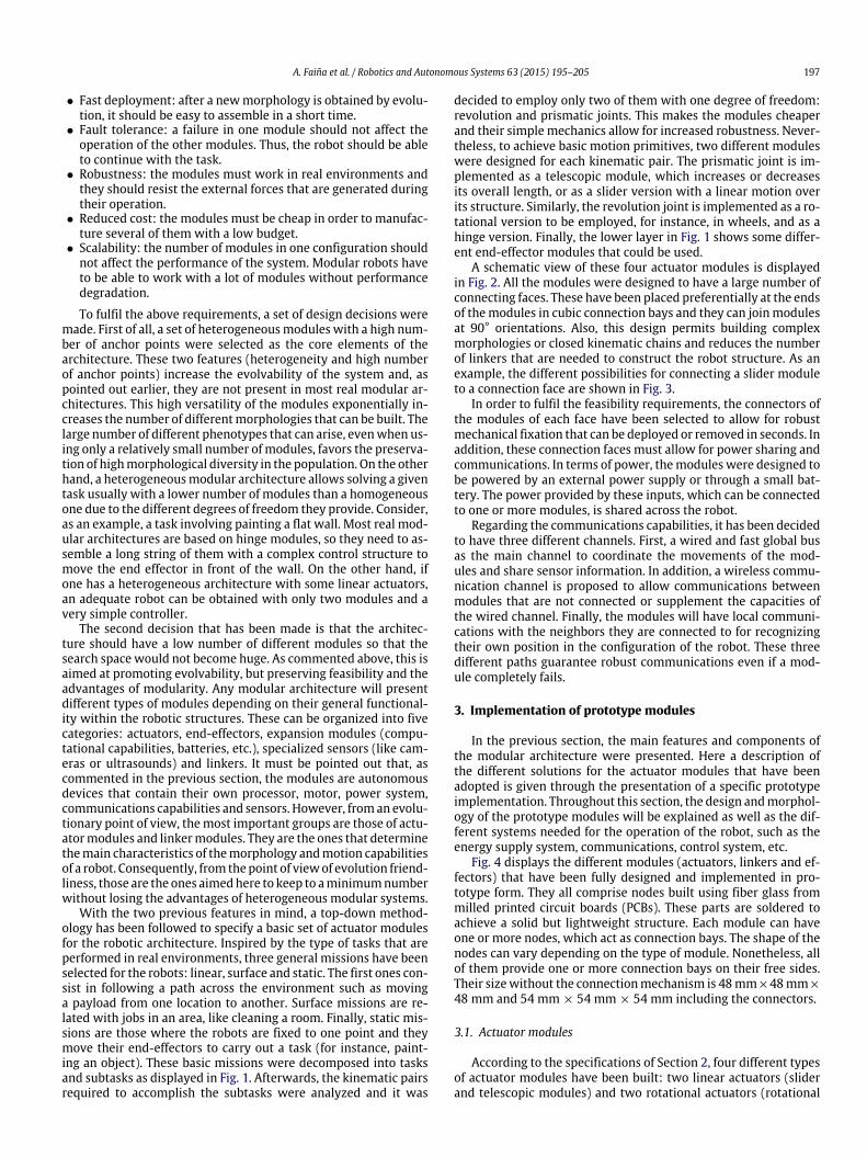
A schematic view of these four actuator modules is displayedin Fig. 2. All the modules were designed to have a large number ofconnecting faces. These have been placed preferentially at the endsof themodules in cubic connection bays and they can joinmodulesat 90° orientations. Also, this design permits building complexmorphologies or closed kinematic chains and reduces the numberof linkers that are needed to construct the robot structure. As anexample, the different possibilities for connecting a slider moduleto a connection face are shown in Fig. 3.
In order to fulfil the feasibility requirements, the connectors ofthe modules of each face have been selected to allow for robustmechanical fixation that can be deployed or removed in seconds. Inaddition, these connection faces must allow for power sharing andcommunications. In terms of power, themodules were designed tobe powered by an external power supply or through a small bat-tery. The power provided by these inputs, which can be connectedto one or more modules, is shared across the robot.
Regarding the communications capabilities, it has been decidedto have three different channels. First, a wired and fast global busas the main channel to coordinate the movements of the mod-ules and share sensor information. In addition, a wireless commu-nication channel is proposed to allow communications betweenmodules that are not connected or supplement the capacities ofthe wired channel. Finally, the modules will have local communi-cations with the neighbors they are connected to for recognizingtheir own position in the configuration of the robot. These threedifferent paths guarantee robust communications even if a mod-ule completely fails.
3. Implementation of prototype modules
In the previous section, the main features and components ofthe modular architecture were presented. Here a description ofthe different solutions for the actuator modules that have beenadopted is given through the presentation of a specific prototypeimplementation. Throughout this section, the design andmorphol-ogy of the prototype modules will be explained as well as the dif-ferent systems needed for the operation of the robot, such as theenergy supply system, communications, control system, etc.
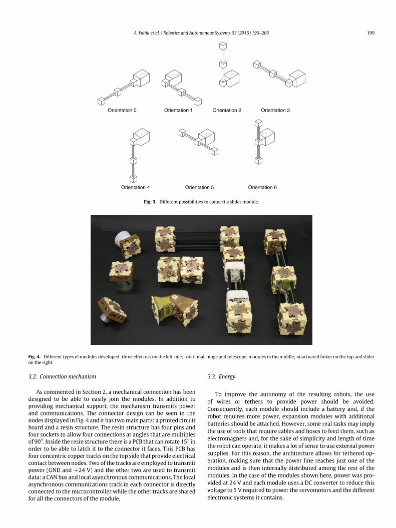
Fig. 4 displays the different modules (actuators, linkers and ef-fectors) that have been fully designed and implemented in pro-totype form. They all comprise nodes built using fiber glass frommilled printed circuit boards (PCBs). These parts are soldered toachieve a solid but lightweight structure. Each module can haveone or more nodes, which act as connection bays. The shape of thenodes can vary depending on the type of module. Nonetheless, allof them provide one or more connection bays on their free sides.Their sizewithout the connectionmechanism is 48mm×48mm×
48 mm and 54 mm × 54 mm × 54 mm including the connectors.
3.1. Actuator modules
According to the specifications of Section 2, four different typesof actuator modules have been built: two linear actuators (sliderand telescopic modules) and two rotational actuators (rotational

198 A. Faiña et al. / Robotics and Autonomous Systems 63 (2015) 195–205
Fig. 1. Diagram of the missions, tasks and sub-tasks considered, and the required actuators and effectors.
Fig. 2. Schematic representation of the four actuator modules.
and hinge modules). They only provide one degree of freedom inorder to increase robustness and they contain different types ofjoints so that it is easy to build most of the kinematic chains usedby real robotic systems. The main features of the actuator modulesare summarized in Table 1.
3.1.1. Slider moduleThe slider module (the one on the right in Fig. 4) is made up of
two cubic nodes, with five connection bays each, joined togetherusing three carbon fiber tubes. Another node, the slider, slidesalong the tubes between the end nodes. The distance between theend nodes is 249 mm and the stroke of the slider node is 189 mm.Its motion is achieved through a servo with a pulley in one of theend nodes that moves a drive belt to which the slider node is fixedthrough a return pulley in the other end node. The sliding nodecontains the electronics of the module.
3.1.2. Telescopic moduleThe telescopic module (the one on the left of the slider module
in Fig. 4) has two cubic nodes on its ends, being the distance
between them variable. One node has the electronic board with allthe control, communications and sensing elements of the module.The other contains a servo with a drive pulley that allows thecontraction and extension of the module.
3.1.3. Rotational moduleThis module (center of Fig. 4, below the linker) has two nodes
that can rotate with respect to each other. A low friction washerbetween the nodes and a shaft prevents misalignments. It is con-figured so as to permit 360° rotations of the nodes with respect toeach other. Among its sensing elements, it can provide the relativerotation between nodes.
3.1.4. Hinge moduleThe hinge module (below the rotational module in Fig. 4) does
not have cubic node in its structure, only one connection bay ineach main block. A shaft joins two main parts built from milledPCBs. These parts rotate relative to each other as a hinge (with therotation axis in one of their ends).
A. Faiña et al. / Robotics and Autonomous Systems 63 (2015) 195–205 199
Orientation 0 Orientation 1 Orientation 2 Orientation 3
Orientation 4 Orientation 5 Orientation 6
Fig. 3. Different possibilities to connect a slider module.
Fig. 4. Different types of modules developed: three effectors on the left side; rotational, hinge and telescopic modules in the middle; unactuated linker on the top and slideron the right.
3.2. Connection mechanism
As commented in Section 2, a mechanical connection has beendesigned to be able to easily join the modules. In addition toproviding mechanical support, the mechanism transmits powerand communications. The connector design can be seen in thenodes displayed in Fig. 4 and it has twomain parts: a printed circuitboard and a resin structure. The resin structure has four pins andfour sockets to allow four connections at angles that are multiplesof 90°. Inside the resin structure there is a PCB that can rotate 15° inorder to be able to latch it to the connector it faces. This PCB hasfour concentric copper tracks on the top side that provide electricalcontact between nodes. Two of the tracks are employed to transmitpower (GND and +24 V) and the other two are used to transmitdata: a CAN bus and local asynchronous communications. The localasynchronous communications track in each connector is directlyconnected to themicrocontroller while the other tracks are sharedfor all the connectors of the module.
3.3. Energy
To improve the autonomy of the resulting robots, the useof wires or tethers to provide power should be avoided.Consequently, each module should include a battery and, if therobot requires more power, expansion modules with additionalbatteries should be attached. However, some real tasks may implythe use of tools that require cables and hoses to feed them, such aselectromagnets and, for the sake of simplicity and length of timethe robot can operate, it makes a lot of sense to use external powersupplies. For this reason, the architecture allows for tethered op-eration, making sure that the power line reaches just one of themodules and is then internally distributed among the rest of themodules. In the case of the modules shown here, power was pro-vided at 24 V and each module uses a DC converter to reduce thisvoltage to 5 V required to power the servomotors and the differentelectronic systems it contains.

200 A. Faiña et al. / Robotics and Autonomous Systems 63 (2015) 195–205
Table 1Main features of the actuator modules.
Slider Telescopic Rotational Hinge
Type of movement Linear Linear Rotational RotationalStroke 189 mm 98 mm 360° (1 turn) 200°Num nodes 3 2 2 2Num connection faces per node 5-4-5 5-5 5-5 1-1Weight 360 g 345 g 250 g 140 g
Fig. 5. Control board for the slider module and its main components.
3.4. Sensors
Every module is able to measure the position of its actuator.Thus, the linear modules have a quadrature encoder with 0.32 mmaccuracy in their position. The rotational modules are servo con-trolled, so, in principle their position is already known. However,to improve precision a circuit has been added to sense the valueof the potentiometer after applying a low pass filter. Additionally,an accelerometer has been incorporated to every module in orderto provide their spatial orientation. This accelerometer, combinedwith the local communications between adjacent modules that isestablished in each attachment face, and that permit identifyingthe type and the face of the neighboring module, permits the de-termination of the morphology and attitude of the robot withoutany external help.
When specific sensors such as cameras, ultrasound sensorsor whatever are required in order to perform a particular task(welding, inspection, measuring, etc.), they are included in specificsensor modules that are attached to one of the free bays of theactuator module that requires it.
3.5. Communications
Communications systems in modular robotics need to ensurethe adequate coordination between modules as well as to respondquickly to possible changes in robotmorphology. This is the reasonwhy different communications channels are used. In this case twoglobal and one local communications channels are considered. Interms of wired global communications, a CAN bus has been chosenas the main communications channel. This bus permits carryingout tasks requiring critical temporal coordination between remotemodules. As a complement to the CAN bus and in order to considercases of isolated modules or CAN bus saturation, a MiWi wirelesscommunications system is implemented.
On the other hand, for local communications, that is, commu-nications that are aimed at the transfer of information between
a node and specific connection bays in its neighbors, an asyn-chronous local communications line has been implemented, whichis mainly used for inter-module identification and to preservesome communications when the global communications systemsfail. As commented above, this allows the detection of the robot’sgeneral morphology through the aggregation of the values of thelocal sensing elements in each module as well as the informationthey have on the modules they are linked to.
Finally, and for programming and debugging purposes, all themodules except the rotational one have a micro-USB connectionto allow communications to an external computer. Fig. 5 shows theprinted circuit board (PCB) of the slider module containing all thecommunications elements.
3.6. Control
In order to be able to implement the control systems withineach module, they all carry their own electronics board with amicro-controller (PIC32MX575F512) and a DC/DC converter forpower supply. The micro-controller is responsible of the low-level tasks of the module: controlling the actuator, managing thecommunications stacks and capturing the values of its sensors.As each actuator module has its own characteristics (number ofconnection faces, encoder type, etc.) and the available space insidethe modules is very limited, a specific PCB has been developed foreach kind of actuator module. As an example, Fig. 5 shows the topand bottom sides of the control board for the slider module.
In addition to the low-level tasks the control elements haveto perform, this solution permits choosing the type of control tobe implemented: centralized or distributed. While in a distributedcontrol scheme, each of the modules contributes to the final be-havior through the control of its own actions depending on its sen-sors or communications to other modules. In a centralized controlscheme, one of the modules would be in charge of controlling theactions of all the other modules, with the advantage of havingredundant units in case of failure. Additionally, all modules em-ploy the CAN bus to coordinate their actions and to synchronize

A. Faiña et al. / Robotics and Autonomous Systems 63 (2015) 195–205 201
their clocks. Obviously, this architecture allows for any intermedi-ate type of control scheme.
4. Some modular robots for useful tasks
The aimof this section is to showhowuseful robots canbe easilybuilt for different tasks by assembling the implemented modulesin ad hoc configurations. In all of these cases the robots werepowered through an external power supply attached by a cableto one of the modules and orders were given to them through aUSB cable connected to the samemodule as the power supply. Thismodulewas taken as themastermodule and bymeans ofmessagesthrough the CAN bus it discovers the other modules that make upthe robot and provides commands to them. It can also discover themorphology of the robot by employing the local communicationsand the orientation of the modules given by their sensors.
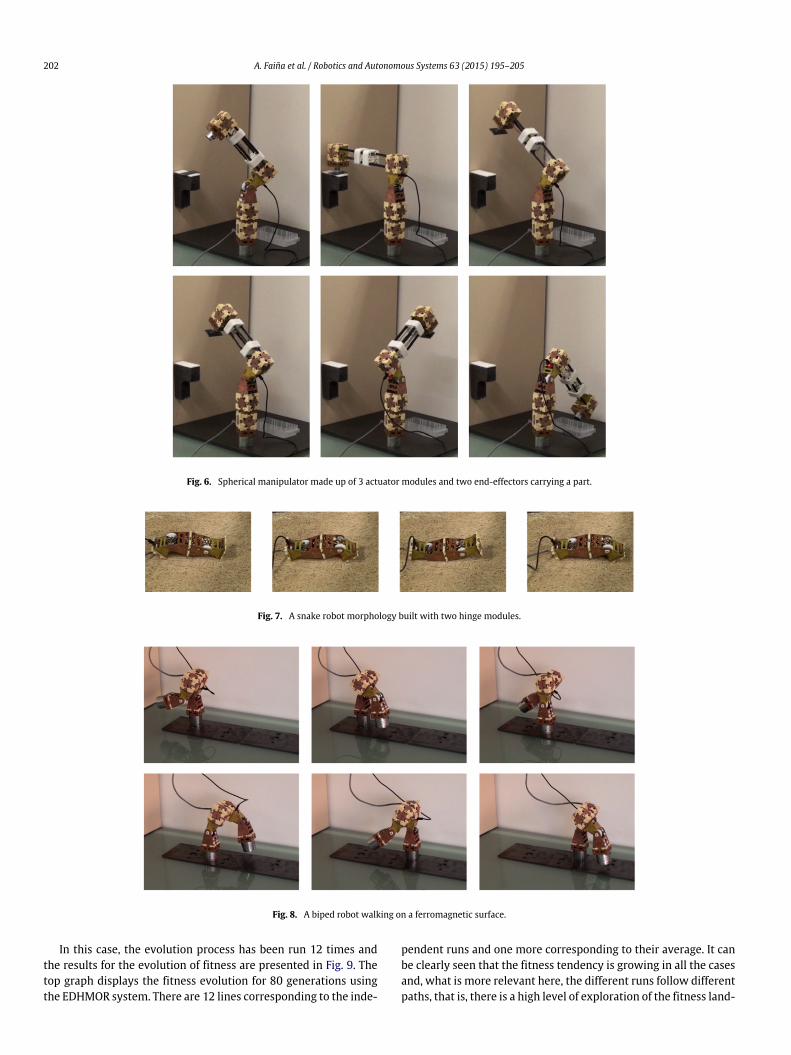
As indicated in the Introduction section, two prototypical tasksin modular robots are locomotion and manipulation. Therefore,some configurations for these tasks will be shown here. Regardingmanipulators, the current architecture allows us to build differentmorphologies like Cartesian, cylindrical and spherical configura-tions or even more complex morphologies such as parallel manip-ulators. For the sake of clarity, a small spherical manipulator hasbeen built using five modules (see Fig. 6). This robot is fixed to theground using a magnetic end effector module (a permanent mag-netwith a coil inside). This allows the robot to be fixedwithout em-ploying energy and it can be unfixed when required. A rotationalmodule, a hinge module and a telescopic module are assembled ina serial chain with a small electromagnet module as an end effec-tor. As shown in the sequence of pictures, the robot is able to pickup a metal part from one place and carry it to a different locationin around 10 s.
Another prototypical configuration in modular robots is thesnake or worm morphology, a serial chain of hinge modules. Thisallows the robot to pass through narrow passages such as pipes.Fig. 7 displays a snake robot configuration, which is built with onlytwo hinge modules. The control parameters allow controlling thedirection of the robot (forward or backwards) and its speed. In thiscase, the movement takes around 8 s but it could be increasedbuilding a snake configuration with more modules.
Finally, in Fig. 8 a bipedal robot built with amore complexmor-phology and greater locomotion capabilities is shown. It is based ona rotational module with two hinge modules attached, each one ofthem with a magnetic module in its end. Thus, the robot is able towalk over ferromagnetic ground and go over obstacles.
This section has briefly shown the capabilities of the architec-ture in terms of being able to build useful robots with differentmorphologies adapted to specific tasks. This versatility is mainlyachieved by using four different types of actuator modules with ahigh number of connection faces. The next section will show howthese features can be exploited by an evolutionary algorithm toachieve well-adapted solutions for different tasks.
5. Evolving robots using this architecture
One of the design requirements of this modular architecturewas its adequateness for use within evolutionary processes. Con-sequently, a verification of whether it meets this requirement isnecessary. It can be postulated that an architecture is amenable toevolution when it allows for easier andmore successful evolution-ary processes. This implies being able to provide for a large numberof possible variations in the resulting robotswhen they are evolvedto solve a given task and ensuring that any of these combinationsof modules produce feasible structures from an operational pointof view so that the need for constraints in the fitness function isavoided.
Feasibility, as indicated in previous sections, is intrinsic tothe way the modules were designed. That is, these modules arecompletely autonomous and they provide enough power to chainseveral together so that any combination ofmodules up to a certainsize will produce feasible structures. This improves evolution asthere is no need to establish structural constraints which wouldmake it much harder.
To address the issue of evolvability, two examples of evolution-ary designs based on the architecture are described in this section.In both, the EDHMOR (Evolutionary Designer of HeterogeneousMOdular Robots) system is applied [32]. It is an automatic designsystem that includes all the elements involved in the process ofevolving robotic structures to solve a target task proposed by thedesigner. It was specifically adapted to be able to handle structuresmade up of the heterogeneous modules defined in the previoussections.
A detailed description of EDHMOR can be found in [32], only itsmain elements will be briefly described here. Three main blocks,algorithm, evaluation, and management make up the system. Thefirst one is in charge of encoding the morphology and control in achromosome to be evolved. A direct tree-like encoding of individu-als is used,with nodes, links between themand control parametersin each node. The chromosomes are evolved using a constructiveevolutionary strategy [32] developed to deal with the high decep-tiveness of the search space, derived from tree based encodingschemes, and to cope with the different time scales involved inthe evolution of morphology and control. The second block of theEDHMOR system, evaluation, includes the definition of the fitnessfunction. It is based on an implicit evaluation methodology thatallows the emergence of original solutions while preserving theirfeasibility by means of a realistic simulator where the physicalconstraints can be easily incorporated and where the main fea-tures of the environment can be properly varied during the eval-uation phase. Specifically, simulation models of the modules havebeen created in theGazebo 3Ddynamic simulator. Finally, the thirdblock consists in the configuration elements and the graphical userinterface, which allow setting up the experiments, storing the re-sults for statistical analysis and evaluating the robot’s behavior ina graphical way [32].
5.1. Linear mission
The first evolutionary design experiment consists in obtaininga robot capable of moving through rough uneven surfaces carryinga payload. Details about the specific experimental setup are de-scribed in [32]. Here the focus will be on the evolution character-istics obtained. The environment contains only an uneven surfaceand the objective is to evolve a robot capable of moving throughthis surface the longest distance possible without dropping a pay-load that is placed on top of it. Regarding the robots, the only el-ement that is common to all of them is a square base to whichthemodules are initially attached and that carries the payload. Thefitness function is directly the traveled distance, although with areward for those individuals that cover a minimum threshold dis-tance and use a low number of modules.
One way of determining how evolvable the architecture is, is tocarry out several runs of the evolutionary process and determinehow many of those produce feasible robots that perform the taskassigned, and how many of those do not achieve the objective. Onthe other hand, onewould expect that, being evolution a stochasticprocess, different runs would produce very different individuals ina problem that is as openly specified as the one proposed here.In other words, there are many structures that should be able toperform the task and, if the architecture has good properties forevolution, there should be a level of variability in the solutionsproduced by different runs.
202 A. Faiña et al. / Robotics and Autonomous Systems 63 (2015) 195–205
Fig. 6. Spherical manipulator made up of 3 actuator modules and two end-effectors carrying a part.
Fig. 7. A snake robot morphology built with two hinge modules.
Fig. 8. A biped robot walking on a ferromagnetic surface.
In this case, the evolution process has been run 12 times andthe results for the evolution of fitness are presented in Fig. 9. Thetop graph displays the fitness evolution for 80 generations usingthe EDHMOR system. There are 12 lines corresponding to the inde-
pendent runs and one more corresponding to their average. It canbe clearly seen that the fitness tendency is growing in all the casesand, what is more relevant here, the different runs follow differentpaths, that is, there is a high level of exploration of the fitness land-

A. Faiña et al. / Robotics and Autonomous Systems 63 (2015) 195–205 203
Fig. 9. Fitness evolution for 12 independent runs in the linear mission (top) andaverage number of modules (bottom).
scape allowed by using the architecture. This is confirmed by thebottom graph of Fig. 9, which shows the average number of mod-ules obtained in the 12 runs and the deviation in each generation. Itis clear that throughout the evolutionary process there are robotsin the populationwith different numbers of modules and, as a con-sequence,with differentmorphologies. In fact, the best robots have
about 12 modules on average, but there is a high diversity rangingfrom 8 to 16 module robots.
These 12 experiments have led to robots that were success-ful in solving the task, although most of them clearly different. Asan example, Fig. 10 displays three robots obtained for three dif-ferent runs and it can be observed how different they are. Obvi-ously, if one desires less variability, a more constrained definitionof the task must be provided and the number of different feasi-ble solutions will be reduced. This was not the objective here asour aim was to show that the architecture allows for many evo-lutionary paths that reach feasible solutions complying with thetask requirements, which is what makes it evolution friendly. Theprevious statement is quite important, as one could think, for in-stance, that a homogeneous modular architecture could also pro-vide for many evolutionary paths. This is true, but in most casesthese would not lead in 80 generations to robots that perform thetask due to the fact that the evolutionary systemwould need to puttogether many more modules in order to be able to carry out thesame actuations, often leading to unfeasible solutions due to powerrequirements, and, in general requiring many more generations.
Just to emphasize the fact that the architecture produces feasi-ble robots, it must be pointed out that all the robots resulting fromthe 12 runs can be easily manufactured using the modular archi-tecture. As an example, Fig. 11 displays a fully functional roboticstructure that corresponds to the solution displayed in the middleimage of Fig. 9.
5.2. Static mission
The second evolutionary design experiment consists in evolvinga robot for a static mission where the robot is in a fixed position,in this case, painting a surface. Again, the specific details of the ex-perimental setup are described in [32], and here the attention willbe focused in what is relevant for the modular architecture. Fig. 13contains screen captures of this second experiment,where the sim-ulation environment is displayed. It consists of a small surface thatis placed at different distances in front of the robot, which starts
Fig. 10. Three different robots obtained using the modular architecture and the EDHMOR system.
Fig. 11. Fully functional prototype robot obtained by evolution and constructed with the modular architecture.
204 A. Faiña et al. / Robotics and Autonomous Systems 63 (2015) 195–205
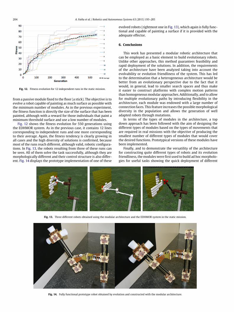
Fig. 12. Fitness evolution for 12 independent runs in the static mission.
from a passivemodule fixed to the floor (a stick). The objective is toevolve a robot capable of painting asmuch surface as possible withthe minimum number of modules. As in the previous experiment,the fitness function is directly the size of the surface that has beenpainted, although with a reward for those individuals that paint aminimum threshold surface and use a low number of modules.
Fig. 12 shows the fitness evolution for 550 generations usingthe EDHMOR system. As in the previous case, it contains 12 linescorresponding to independent runs and one more correspondingto their average. Again, the fitness tendency is clearly growing inall cases and the high diversity of solutions is confirmed, becausemost of the runs reach different, although valid, robotic configura-tions. In Fig. 13, the robots resulting from three of these runs canbe seen. All of them solve the task successfully, although they aremorphologically different and their control structure is also differ-ent. Fig. 14 displays the prototype implementation of one of these
evolved robots (rightmost one in Fig. 13), which again is fully func-tional and capable of painting a surface if it is provided with theadequate effector.
6. Conclusions
This work has presented a modular robotic architecture thatcan be employed as a basic element to build evolutionary robots.Unlike other approaches, this method guarantees feasibility andrapid deployment of the solutions. In addition, the requirementsof the architecture have been analyzed taking into account theevolvability or evolution friendliness of the system. This has ledto the determination that a heterogeneous architecture would bebetter from an evolutionary perspective due to the fact that itwould, in general, lead to smaller search spaces and thus makeit easier to construct platforms with complex motion patternsthanhomogeneousmodular approaches. Additionally, and to allowfor multiple evolutionary paths by introducing flexibility in thearchitecture, each module was endowed with a large number ofconnection faces. This feature increases the possiblemorphologicaldiversity in the population and allows the generation of welladapted robots through mutations.
In terms of the types of modules in the architecture, a topdown approach has been followed with the aim of designing thedifferent types of modules based on the types of movements thatare required in real missions with the objective of producing thesmallest number of different types of modules that would coverthe desired functions. Prototypical versions of these modules havebeen implemented.
Finally, and to demonstrate the versatility of the architecturefor constructing quite different types of robots and its evolutionfriendliness, themoduleswere first used to build ad hocmorpholo-gies for useful tasks showing the quick deployment of different
Fig. 13. Three different robots obtained using the modular architecture and the EDHMOR system in the static mission.
Fig. 14. Fully functional prototype robot obtained by evolution and constructed with the modular architecture.
A. Faiña et al. / Robotics and Autonomous Systems 63 (2015) 195–205 205
robots. Then themorphology and control of severalmodular robotshave been evolved for linear and static missions. These tests haveshown that a large number of different robotic structures can eas-ily be obtained that successfully carry out the proposed tasks, high-lighting the evolvability of the architecture.
References
[1] R. Pfeifer, F. Iida, J. Bongard, New robotics: design principles for intelligentsystems, Artif. Life 11 (1–2) (2005) 99–120.
[2] R. Pfeifer, J. Bongard, How the Body Shapes theWayWe Think: A New View ofIntelligence, MIT Press, 2007.
[3] R. Pfeifer, F. Iida, Morphological computation: connecting body, brain andenvironment, in: Creating Brain-Like Intelligence, 2005.
[4] K. Matsushita, M. Lungarella, C. Paul, Locomoting with less computation butmore morphology, 2005, pp. 2008–2013.
[5] C. Paul, Morphological computation: a basis for the analysis of morphologyand control requirements, Robot. Auton. Syst. 54 (8) (2006) 619–630.
[6] M. Matarić, D. Cliff, Challenges in evolving controllers for physical robots,Robot. Auton. Syst. 19 (1) (1996) 67–83.
[7] D. Floreano, F.Mondada, Evolution of homing navigation in a realmobile robot,IEEE Trans. Syst. Man Cybern. B 26 (3) (1996) 396–407.
[8] D. Floreano, L. Keller, Evolution of adaptive behaviour in robots by means ofDarwinian selection, PLoS Biol. 8 (1) (2010) e1000292.
[9] K. Sims, Evolving virtual creatures, in: Proceedings of the 21st Annual Confer-ence on Computer Graphics and Interactive Techniques—SIGGRAPH’94, 1994,pp. 15–22.
[10] M. Komosin’ski, The Framsticks system: versatile simulator of 3D agents andtheir evolution, Kybernetes 32 (1–2) (2003) 156–173.
[11] N. Chaumont, R. Egli, C. Adami, Evolving virtual creatures and catapults, Artif.Life 13 (2) (2007) 139–157.
[12] M. Mazzapioda, A. Cangelosi, S. Nolfi, Evolving morphology and control: adistributed approach, in: IEEE Congress on Evolutionary Computation, No. IV,2009, pp. 2217–2224.
[13] J.B. Pollack, H. Lipson, The GOLEM project: evolving hardware bodies andbrains, in: Proceedings of the Second NASA/DoD Workshop on EvolvableHardware, 2000, pp. 37–42.
[14] N. Cheney, R. MacCurdy, J. Clune, H. Lipson, Unshackling evolution, in: Pro-ceeding of the Fifteenth Annual Conference on Genetic and EvolutionaryComputation Conference—GECCO’13, 2013, p. 167.
[15] J. Hiller, H. Lipson, Automatic design and manufacture of soft robots, IEEETrans. Robot. 28 (2) (2012) 457–466.
[16] P. Funes, J. Pollack, Evolutionary body building: adaptive physical designs forrobots, Artif. Life 4 (4) (1998) 337–357.
[17] I. Macinnes, E. Di Paolo, Crawling out of the simulation?: Evolving real robotmorphologies using cheap, reusable modules, 2003.
[18] G.S. Hornby, H. Lipson, J.B. Pollack, Evolution of generative design systems formodular physical robots, in: IEEE International Conference on Robotics andAutomation, 2001, pp. 4146–4151.
[19] K. Stoy, D. Brandt, D.J. Christensen, Self-Reconfigurable Robots: An Introduc-tion, Vol. 18, MIT Press, 2010, pp. 237–240.
[20] M. Yim, W.-M. Shen, B. Salemi, D. Rus, M. Moll, H. Lipson, E. Klavins,G.S. Chirikjian, Modular self-reconfigurable robot systems, in: IEEE Roboticsand Automation Magazine, IEEE, 2007.
[21] T. Matsumaru, Design and control of the modular robot system: TOMMS,in: Proc. 1995 IEEE Int. Conf. Robot. Autom., vol. 2, 1965, pp. 2125–2131.
[22] W. Chen, E. Hui, L. Ha, I. Chen, Interactive-motion control of modularreconfigurable manipulators, no. October, 2003, pp. 1620–1625.
[23] S. Kernbach, F. Schlachter, R. Humza, J. Liedke, S. Popesku, S. Russo, T. Ranzani,L. Manfredi, C. Stefanini, R. Matthias, C. Schwarzer, B. Girault, P. Alschbach,E. Meister, O. Scholz, Heterogeneity for increasing performance and reliabilityof self-reconfigurablemulti-robot organisms, in:Workshop on ReconfigurableModular Robotics at IEEE/RSJ International Conference on Intelligent Robotsand Systems, 2011, pp. 1–8.
[24] I. Chen, J.W. Burdick, Determining task optimal modular robot assembly con-figurations, in: IEEE International Conference on Robotics and Automation,1995, pp. 132–137.
[25] J. Han, K.W. Chung, Y. Youm, S.H. Kim, Task based design ofmodular robotma-nipulator using efficient genetic algorithms, in: IEEE International Conferenceon Robotics and Automation, 1997, pp. 507–512.
[26] O. Chocron, Evolutionary design of modular robotic arms, Robotica 26 (03)(2007) 323–330.
[27] S. Farritor, S. Dubowsky, On modular design of field robotic systems, Auton.Robots 10 (1) (2001) 57–65.
[28] C. Leger, Automated synthesis and optimization of robot configurations, in:Proceedings of the 1998 ASME Design Engineering Technical Conferences,1999, pp. 13–16.
[29] O. Chocron, Evolving modular robots for rough terrain exploration, 46 (2007)23–46.
[30] H.H. Lund, Co-evolving control and morphology with LEGO robots, in: H. Fu-mio, R. Pfeifer (Eds.), Morpho-Functional Machines: The New Species,Springer, Japan, 2003, pp. 59–79.
[31] A.J.I. Daniel Marbach, Co-evolution of configuration and control for homo-geneous modular robots, in: Eighth Conference on Intelligent AutonomousSystems, 2004.
[32] Andrés Faíña, Francisco Bellas, Fernando López-Peña, Richard J. Duro,EDHMoR: Evolutionary designer of heterogeneous modular robots, Eng. Appl.Artif. Intell. 26 (10) (2013) 2408–2423.
Andrés Faiña received the M.S. degree in Industrial Engi-neering in 2006 and Ph.D. in 2011 from the University of ACoruña, Spain. He is currently working as a post-doctoralresearcher in the ITUniversity of Copenhagen. Hismain in-terests include modular and self-reconfigurable robotics,mobile robotics and electronic and mechanical design.
Francisco Bellas is a Profesor Titular at the University ofA Coruña, Spain. He received the B.S. and M.S. degrees inPhysics from the University of Santiago de Compostela,Spain, in 2001, and a Ph.D. in Computer Science from theUniversity of A Coruña in 2003. He is amember of the Inte-grated Group for Engineering Research at the University ofA Coruña. His current research activities are related to evo-lutionary algorithms applied to artificial neural networks,multiagent systems and robotics.
Félix Orjales received the M.S. degree in Industrial Engi-neering in 2010 from the University of León, Spain. Heis currently working towards a Ph.D. degree in the De-partment of Industrial Engineering at the University ofA Coruña. He is currently a researcher at the IntegratedGroup for Engineering Research. His research activities arerelated to electronics and unnamed aerial vehicles.
Daniel Souto received the M.S. degree in Industrial Engi-neering in 2007 from the University of A Coruña, Spain. Heis currently working towards a Ph.D. degree in the Depart-ment of Industrial Engineering at the same University. Heis currently a researcher at the Integrated Group for En-gineering Research. His research activities are related toautomatic design and mechanical design of robots.
Richard J. Duro received an M.S. degree in Physics fromthe University of Santiago de Compostela, Spain, in 1989,and a Ph.D. in Physics from the sameUniversity in 1992. Heis currently a Catedrático de Universidad in the Departmentof Computer Science and Head of the Integrated Groupfor Engineering Research at the University of A Coruña.His research interests include higher order neural networkstructures, signal processing and autonomous and evolu-tionary robotics.