an assessment of the strength of knots and splices used as ... · department of mechanical...
TRANSCRIPT

Introduction
Ropes are widely exploited in sailing. Their use onyachts may be broadly divided into two categories,namely the standing and running rigging. Standingrigging consists of the structural components thatsupport the mast and spars, together with equipment
such as guard rails which are present for reasons ofsafety. The running rigging is used to hoist and/orcontrol the sails. Halyards are used to hoist the sailsinto position; sheets are attached to the sails and areused primarily to control the angle of the sails to theboat’s centreline, and therefore the wind. The runningrigging will also generally include ropes that are usedto control the position of moveable components of theboat, which are used for fine adjustment of the sails.
Many different methods have evolved that allowone rope to be attached to another, to a fixed point orto a sail. One common method is to create an eye witha knot, or a splice, or by binding or stitching the end ofthe rope to the standing part with twine. This lastmethod is called seizing. A knot is defined as ‘a way of
© 2006 isea Sports Engineering (2006) 9, 1–13 1
An assessment of the strength of knots and splicesused as eye terminations in a sailing environment
K.A. Milne and A.J. McLaren
Department of Mechanical Engineering, University of Strathclyde, Glasgow, UK
Abstract
Research into knots, splices and other methods of forming an eye termination has been limited,despite the fact that they are essential and strongly affect the performance of a rope. The aim ofthis study was to carry out a comprehensive initial assessment of the breaking strength of eye ter-minations commonly used in a sailing environment, thereby providing direction for further workin the field.
Supports for use in a regular tensile testing machine were specially developed to allow indi-vidual testing of each sample and a realistic spread of statistical data to be obtained. Over 180break tests were carried out on four knots (the bowline, double bowline, figure-of-eight loopand perfection loop) and two splices (three-strand eye splice and braid-on-braid splice). Thefactors affecting their strength were investigated. A statistical approach to the analysis of theresults was adopted.
The type of knot was found to have a significant effect on the strength. This same effect wasseen in both types of rope construction (three-strand and braid-on-braid). Conclusions were alsodrawn as to the effect of splice length, eye size, manufacturer and rope diameter on the breakingstrength of splices. Areas of development and further investigation were identified.
Keywords: break, knot, rope, sailing, splice, strength
Correspondence address:Dr. A.J. McLarenDepartment of Mechanical EngineeringUniversity of StrathclydeGlasgowUKTel: +44 (0) 141 548 3104E-mail: [email protected]
9.1.1 Sports E77 McLaren 27/7/06 2:38 pm Page 1

joining or securing lengths of rope, thread, or otherstrands by tying the material together or arounditself’. A splice is defined as a way ‘to join ends of ropesby intertwining strands’. Unlike knots, a specific spliceis suitable only for a specific type of rope.
The ropes used in sailing are similar in appearanceto those utilised by climbers, but the materials usedare different. Climbing ropes are designed to absorbshock loads in the event of a fall, and are of relativelylow stiffness. By contrast, sailing ropes need to havehigh stiffness to preserve precise control by minimis-ing elastic extension. Whereas it is generally acceptedthat climbing ropes do not fail, either at a knot, orgenerally, unless loaded over an edge (Schubert, 2002;Bailie, 2000), sailing ropes are subject to failure, par-ticularly near the ends where high degrees of wear andchafe are possible during extended use. In addition,sailing ropes are subjected to high static loadings,upon which considerable dynamic fluctuations aresuperimposed. These ropes are also prone to ultraviolet attack due to prolonged exposure in the marineenvironment.
A wealth of information has been published con-cerning the suitability of the various methods offorming a loop termination. This information isavailable in books specifically dedicated to knots andsplices, e.g. Jarman (2000), Shaw (2004), and Pawson(2001). It may also be found in standard sailingtextbooks (Cunliffe, 2000). Recent articles in thesailing press demonstrate the continuous developmentof ropes and splicing techniques (James, 2003;Pawson, 2005).
The published research on polymeric ropes issomewhat limited. Manes (2002) has reviewed workcarried out on the structure of ropes for rock climbing.Leech (2002) considers the hierarchical structure builtup from individual strands, bundles, and sub-ropes, tomake the overall cable. He also considers the frictionalload transfer between the elements of the rope. Pan &Brookstein (2002) have reviewed the recent work thathas been carried out on the modelling of polymerropes.
The theory of knots has stimulated some interest inthe mathematics community. This is typified by theFields Medal winning work of Vaughan Jones, asreviewed by King (1986). At a fundamental level, theeffect of a knot on the strength of a single polymer
strand is discussed by Saitta et al. (1999). This is moreof interest to the polymer scientist due to the micro-scopic scale of the fibres in question. Wu (1993)considered friction and slippage between the strandsof polymeric ropes, and made some observations con-cerning slippage in end terminations.
A particular method for forming an eye terminationmight be selected because it is easy to form or release,because it holds securely, because it is compact andwill slide over apparatus easily, or because it is consid-ered relatively strong. The presence of the eyetermination can have a significant effect upon thefatigue life of a line, its response under dynamicloading and its static breaking load. While muchexperimental and analytical work has been conductedupon synthetic ropes, knowledge about eye termina-tions is limited. Advice on how to create eyeterminations is generally based upon one-off tests ortradition. There is no definitive guide about whichknot to choose or how to form a splice in order to getthe highest splice efficiency, which is defined as theratio of the breaking strength with the eye to the ropestrength.
Limited mathematical modelling has been carriedout. Maddocks & Keller (1987) propound themechanics of some simple hitches while Leech (2003)models the stresses in some commonly used splices.However, such models are founded upon numerousassumptions and, although they help to understandthe mechanics involved, they do not provide accuratepredictions of the breaking loads or the effect ofchanging one of the huge number of variables, such asthe maker of the eye (referred to hereafter as the man-ufacturer), rope type, eye size, length of the workingend or the type of loading. This project has attemptedto carry out an assessment of the static strength ofknots and splices used in a sailing environment and thefactors that affect this strength.
The aim of this study was to carry out a compre-hensive preliminary assessment of the static breakingstrength of several common eye terminations. Theseincluded four knots – the bowline, double bowline,perfection loop and figure-of-eight loop – and twosplices – the three-strand eye splice and the braid-on-braid splice. The effect of various factors upon thebreaking strength of the line was investigated and thepractical relevance of the results discussed.
2 Sports Engineering (2006) 9, 1–13 © 2006 isea
The strength of knots and splices K.A. Milne and A.J. McLaren
9.1.1 Sports E77 McLaren 27/7/06 2:38 pm Page 2

Experimental procedure
This section describes the programme of experimentalwork. First, the determination of the initial baselinestrength of each rope type and diameter is described.Secondly, the preparation of knots and the method bywhich eye splices were prepared, using the specificmethod appropriate to each rope type, is discussed.Thirdly, the apparatus used to test the loops isdetailed. Finally, the procedure used to test thestrength of the knots and splices, and the means bywhich data were recorded, is reviewed.
Determination of rope strengthTwo different commercially available types of ropewere used to make the knots and splices. Both ropetypes were manufactured by Liros Ropes Ltd(Germany). The first was a 16-plait braid-on-braidpolyester rope, sold as the LIROS Top Cruising rope.The second was a three-strand twisted pre-stretchedpolyester rope, sold as the LIROS Prestretch rope. Inthe course of the project, ropes of 6, 8 and 12 mmdiameter were used.
The breaking loads of all diameters of three-strandrope were found. Only the breaking load of the 8 mmbraid-on-braid rope was found, due to the limitationsof the project. The rated breaking load was taken forthe 6 and 12 mm braid-on-braid ropes. The testingwas carried out by Marlow Ropes (now part of BridonInternational Ltd) on an AJT horizontal tensile testmachine, as specified in BS EN 919 (1995). For eachsample set, three samples were tested and the meanstatic break load was calculated. The results are shownin Table 1.
Sample preparationThe knots were made using both types of 8 mm rope.Splices are specific to the type of rope construction. A
three-strand eye splice was manufactured from thepre-stretched rope while a braid-on-braid splice wasmanufactured from the braid-on-braid rope. The eyesize was defined as the inside length of the eye,measured with a flexible tape. The working end is theunloaded end of the rope.
All knot and splice samples were finished in thesame manner. A mark was made 1.3 m along thestanding part of the rope, measuring from the crotchof the eye. The rope was whipped either side of themark, cut and the end sealed by melting.
KnotsThe four knots investigated were the bowline, doublebowline, figure-of-eight loop and perfection loop,shown in Fig. 1. Each sample was prepared with a100 mm working end and a 150 mm internal eye size.
Three-strand eye spliceThe eye splices were manufactured as shown in Fig. 2.Jarman (2000) gives a step-by-step guide of how to dothis. The standard eye splice had four tucks and a15 cm internal eye size. It was manufactured from an8 mm diameter rope by the author. Once the splicewas completed the working ends were cut to a lengthof about 5 mm. The splice was rolled under foot threetimes to settle it.
The following factors were varied during the study,to find their effect on spice efficiency:
● number of tucks● manufacturer● eye size● rope diameter.
The factors were varied one at a time to allow directcomparison of the results. This method did not,however, allow interdependency of the factors to bestudied.
Splices with two, three, four and eight tucks weretested. Samples were prepared by three different man-ufacturers: two adult males and one adult female, all ofwhom had little previous experience of making splices.The different eye sizes tested were 8, 15 and 25 cm.8 cm was the smallest eye that could pass over theshackle used in the test rig. Rope diameters of 6, 8 and12 mm were tested.
© 2006 isea Sports Engineering (2006) 9, 1–13 3
K.A. Milne and A.J. McLaren The strength of knots and splices
Table 1 Average breaking load for the four types of rope tested byMarlow Ropes (now part of Bridon International Ltd)
Type of rope Diameter (mm) Average break load (kN)
3-strand 6 9.223-strand 8 12.563-strand 12 29.23Braid-on-braid 8 14.42
9.1.1 Sports E77 McLaren 27/7/06 2:38 pm Page 3

4 Sports Engineering (2006) 9, 1–13 © 2006 isea
The strength of knots and splices K.A. Milne and A.J. McLaren
a b c d
Figure 1 Knots investigated in the current work: a) bowline, b) double bowline, c) figure-of-eight loop, d) perfection loop.
Figure 2 Sequence of operations involved in the manufacture of aneye splice in three-strand prestretched rope. After Jarman (2000).
Braid-on-braid eye spliceThe braid-on-braid splices were manufactured asshown in Fig. 3. Again the reader is referred to Jarman(2000) for detailed instructions.
The factors considered for this splice were:
● splice length● eye size● rope diameter.
Again eye sizes of 8, 15 and 25 cm and ropediameters of 6, 8 and 12 mm were tested. Variation ofthe splice length for a braid-on-braid splice was moredifficult. Unlike the three-strand eye splice, theinternal construction of the braid-on-braid splice,shown in Fig. 4, has an infinite number of possiblevariations. Dimension OA dictates the final length ofthe splice. Dimension DE dictates the length forwhich the sheath passes through the core. Dimension
9.1.1 Sports E77 McLaren 27/7/06 2:38 pm Page 4

CD is critical in the construction of the splice, as itdictates the amount of sheath that is pushed back. If itis too short it becomes very difficult to milk the sheathover the splice from O to A. Dimension CD could,therefore have an effect upon the breaking strength ofthe rope. If it is very short the sheath has to be strainedexcessively to make it pass over the splice. Thisprocess involves a lot of abrasion.
Initially, just two samples were tested for eachvariation in splice length. Where differences inbreaking load were significant the sample sets were
extended. Seven different splice constructions weretested. These are labelled as Types I to VII. Type I isthe standard as described in Jarman (2000). Type IIvaried the relative length of CD to OA. Type III variedthe absolute length of the splice. Types IV to VIIvaried the amount of core overlap in the internal con-struction. The variations are summarised in Table 2and Fig. 5. ‘Fid’ implies the length of one Swedish fid(the hollow tool shown in Fig. 3), which is approxi-mately 14 cm. For accuracy the length was measuredwith a tape measure.
© 2006 isea Sports Engineering (2006) 9, 1–13 5
K.A. Milne and A.J. McLaren The strength of knots and splices
Figure 3 Sequence of operations involved in the manufacture of a braid-on-braid splice.The ‘fid’, referred to in the text, and in Table 2, is the metal needle, approximately 14 cmin length shown in the Figure. After Jarman (2000).
A
B
CD
E
B
C
O
OA
D
E
B
A
DB
Figure 4 Internal construction of the braid-on-braid splice, showingsignificant points in the structure. The distances between thesepoints define the geometry of the splice in Table 2.
Table 2 Splice constructions for braid-on-braid splices. Here, the geometry is characterised by the lengths of ropebetween the significant points labelled in Figs. 3 and 4. ‘Fid’ refersto the length of a Swedish fid, the 14 cm long splicing needleshown in Fig. 2
Splice length OA DE CD
Type I 1 fid 2⁄3 fid 1 fidType II 1 fid 1⁄3 fid 1 fidType III 1⁄2 fid 1⁄3 fid 1⁄2 fidType IV See Fig. 5Type V See Fig. 5Type VI See Fig. 5Type VII See Fig. 5
9.1.1 Sports E77 McLaren 27/7/06 2:38 pm Page 5

Test apparatusThree rope manufacturers were contacted todetermine the method by which eye splice strengthsare currently measured. The companies concernedwere:
● New England Ropes, Fall River, MA, USA (T.DaCosta)
● Liros Ropes, Lichtenberg, Germany (K.Rosenberger)
● Marlow Ropes, Hailsham, UK (T. Scofield) (nowpart of Bridon International Ltd)
The current method for testing eye terminations inindustry involves creating a line with an eye in eachend. The eyes are then looped over pins in a tensiletesting machine and the line is loaded at a constantcrosshead velocity until failure occurs. The line willalways fail at its weakest point (Pan, 1996), which, ifthe rope has been manufactured correctly, should lie atone of the eye terminations. The major limitation ofthis test method is that the breaking load of the weakereye is invariably measured. Statistically, then, a set ofdata obtained from this test will be inherently flawed.
The method adopted for this work, an adaptationof the support used to drop test dynamic moun-taineering ropes, BS EN 892 (1996), allowed eachindividual eye termination to be tested. The eye ter-mination was looped over a shackle that was attached
6 Sports Engineering (2006) 9, 1–13 © 2006 isea
The strength of knots and splices K.A. Milne and A.J. McLaren
Figure 5 Internal construction of Type IV to VII splices, showing significant points in the structure.The distances between these points define the geometry of the splice in Table 2.
Location ofstopper knot
To knot orspice
Figure 6 Upper support. Utilised in the present work for theattachment of the standing part of the rope to the tensile testingmachine. The position of the stopper knot and eye are indicated.
9.1.1 Sports E77 McLaren 27/7/06 2:38 pm Page 6
to the moving crosshead of a tensile testing machine.As illustrated in Fig. 6, the standing part of the ropewas wrapped around a 100 mm diameter drum, passedthrough a clamp and then a stopper knot was tied inthe end. The stopper knot prevented the rope fromslipping through the clamp under tension. The upperand lower supports were carefully designed such thatneither presented a greater weakness in the rope thanthe eye termination itself; there were no sharp edgesand the rope did not follow any tight bends over thesupports. Furthermore, to prevent failure at thestopper knot, the rope was wrapped at least twicearound the drum, thereby reducing the tension in therope at the clamp. A test was considered valid whenthe rope broke at the eye termination.
The disadvantage of this method was that, as therope could not be totally constrained at the drum, itdid not allow accurate measurement of the elongation.The measured value of elongation included the strainfor the entire length of rope, from the eye terminationto the clamp, and any slack that had existed in the set-up. Bedding-in (loading of the sample prior to themain run to a value well below its breaking strength)was used to take up the slack and thereby limit theextent of this problem.
Sample testingThe samples were tested in a Tinius Olsen 81000vertical tensile testing machine with a load capacity of200 000 lb (4325 kN) and a maximum stroke of 2 m,in order to find their breaking load. A mark was madeon each sample 300 mm from the crotch of the eye.The standing part of the sample was wrapped twicearound the drum and the mark was aligned with itshorizontal longitudinal axis. The standing part wasthen passed through the clamp and a stopper knot wastied in the end. The upper support was clamped intoposition in the tensile testing machine. The eye termi-nation was threaded through a shackle attached to themoving crosshead.
The samples were bedded-in by increasing the loadto 10% of the rope’s rated breaking load three times(except for Type VII braid-on-braid splices, where thefailure load was too unpredictable). Each sample wasthen loaded until failure by applying a constantcrosshead speed of 1 mm/s. The experiment wasrepeated at least five times for each sample set.
The breaking load was defined as the highest loadreached in the rope prior to complete failure. In a real-life situation the load would not be relaxed after theinitial failure and, having reached the maximumsupported load, catastrophic failure would follow. Forthe three-strand pre-stretched rope the maximumsupported load was attained just before the first strandbroke. After this initial failure, relaxation of the twistedstructure occurred, and the load in the line reducedsignificantly. The other two strands would subse-quently break at much lower loads. In comparison, inthe braid-on-braid splices, the core of the rope failedfirst. The sheath finally failed at an even higher load.
An analogue plotter, a dial gauge and a computerprogram, which took measurements at 3 secondintervals, logged the breaking load and elongation.The data obtained from the computer is given here.These measurements were the most precise (to thenearest 0.01 lb or 0.22 N), but data was captured onlyonce every three seconds, meaning that the maximumbreaking load recorded was marginally lower than theactual maximum breaking load. All values wereverified against those obtained from the analogueplotter and the dial gauge.
Results and analysis
This section presents an analysis of the results of thetests carried out. First, a description of the statisticaltechniques utilised is presented. Secondly, a comparisonbetween the strengths of the four knots is discussed.Next, the factors that affect the strength of three-strandeye splices are analysed. Finally, the variation instrength of braid-on-braid eye splices is described.
Statistical analysisThe inherent variance in the breaking strength ofropes is significant. Ropes are discontinuous struc-tures manufactured by the twisting or braiding ofyarns of fibre. The tensile strength of a given length ofrope is dependent upon many factors, including thechemistry of the fibres, the manufacturing method,the number of slack and damaged fibres present frommanufacture (Phoenix, 1979), and the type of ropeconstruction. Further variability is introduced byhuman error when an eye termination is made in arope. There are also errors in the testing technique.
© 2006 isea Sports Engineering (2006) 9, 1–13 7
K.A. Milne and A.J. McLaren The strength of knots and splices
9.1.1 Sports E77 McLaren 27/7/06 2:38 pm Page 7
These factors are difficult to control. The conse-quence is that no two samples will be exactly the sameand there will be random variance in the measuredbreaking loads. One alternative is to try to controlthese factors. However, within the limits of thisproject, this was impracticable. Further, on the basisthat such errors would exist in any eye terminationcreated in the real world, it was decided that it was infact essential to include these variations so that the realsignificance of any results could be demonstrated.However, drawing conclusions from data sets withsuch a degree of variance can become very difficult. Astatistical approach was therefore adopted.
The sample mean and so the average knot or spliceefficiency were calculated for each sample set. Only theefficiency is quoted here. Knot efficiency is defined as:
knot efficiency =
The sample standard deviation was also calculated inorder to find the estimated standard error (ESE) of thedata. The ESE indicates how representative the samplemean is of the population mean. The highest ESE forany sample set was calculated as 45.1% of the averagebreaking load; however this was for a particularlyunpredictable sample set. The next highest ESE was5.44% – most of the errors were around 3%. It wasconcluded that the sample mean was a sufficientlyaccurate point estimate of the population mean.
The effect of varying a factor was initially analysedby comparing the means and spreads of sample data.Even though trends appeared, it was difficult to stateobjectively whether the factor had an effect due to thedegree of variance in the results. A one-way analysis ofvariance (ANOVA) was carried out in these cases toallow an objective decision to be made.
Montgomery et al. (2001) give a detailed explana-tion of ANOVA and hypothesis testing. The nullhypothesis posed was that changing the factor had noeffect. Using a statistics programme the P-value(0"P"1) for the sample set was calculated. In general, ifthe P-value is small then the evidence against the nullhypothesis is very strong. It can be concluded that thefactor in question does affect the breaking load of therope. If the P-value is large then the evidence for thenull hypothesis is strong. It can be concluded that thefactor does not affect the breaking load of the rope.
line strength with knotline strength
ANOVA assumes that the population distribution isnormal, that the observations are independent andthat, except for variance caused by the factor, varianceis the same at each treatment level (each level ofvariation of the factor). These assumptions wereverified by examining plots of the residuals. Theanalysis was carried out using the MINITABcomputer programme.
KnotsThe standing part of the rope, as it exits an eye, willcarry the entire load. The working or free end willcarry no load. The load is transferred from thestanding part to the working part through the knot orsplice until the load is shared equally at the crotch.Load transference occurs through friction and contactbetween the different parts of the rope. In a knot,because of the complex geometry, the load decreasessuddenly where parts of the rope come into contact(Maddocks and Keller, 1987).
The mechanisms of failure in an eye are extremelycomplex. In any length of rope the shortest fibres willinitially take the entire load and fail first. The load willthen redistribute and can be increased further until thelonger fibres start to fail. Failure occurs catastrophi-cally when a certain number of fibres have failed. In aneye the fibres fail due to stress created by contact,friction or bending, or by abrasion. Abrasion occurs asthe knot tightens: fibres both slide over one anotherand move across one another at an angle, in a cuttingaction (Leech, 2003).
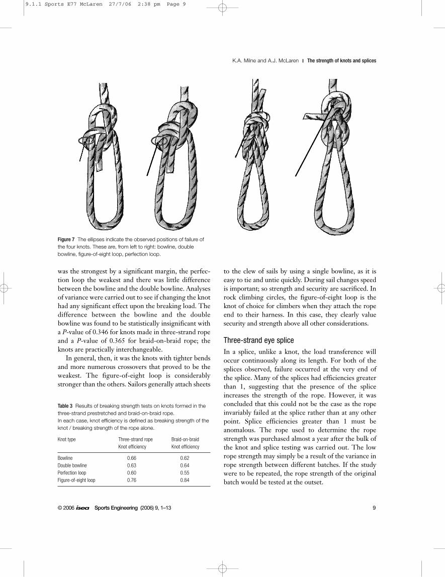
The position of failure of the knots was observed,with the aid of a high-speed camera. Both the figure-of-eight loop and the perfection loop failed just wherethe standing part enters the body of the knot, as shownin Fig. 7. The position of failure of the bowline anddouble bowline was not clear. It appeared to fail at thefirst bend after the standing part enters the knot.However, failure occasionally occurred in otherpositions. Failure where the standing part enters theknot makes sense: the entire standing part of the ropewill see the entire load but, at the point of entry,stresses due to contact and friction are superimposed.
As shown in Table 3, the general trend in thebreaking load was the same for both the three-strandand the braid-on-braid rope; the figure-of-eight loop
8 Sports Engineering (2006) 9, 1–13 © 2006 isea
The strength of knots and splices K.A. Milne and A.J. McLaren
9.1.1 Sports E77 McLaren 27/7/06 2:38 pm Page 8
was the strongest by a significant margin, the perfec-tion loop the weakest and there was little differencebetween the bowline and the double bowline. Analysesof variance were carried out to see if changing the knothad any significant effect upon the breaking load. Thedifference between the bowline and the doublebowline was found to be statistically insignificant witha P-value of 0.346 for knots made in three-strand ropeand a P-value of 0.365 for braid-on-braid rope; theknots are practically interchangeable.
In general, then, it was the knots with tighter bendsand more numerous crossovers that proved to be theweakest. The figure-of-eight loop is considerablystronger than the others. Sailors generally attach sheets
to the clew of sails by using a single bowline, as it iseasy to tie and untie quickly. During sail changes speedis important; so strength and security are sacrificed. Inrock climbing circles, the figure-of-eight loop is theknot of choice for climbers when they attach the ropeend to their harness. In this case, they clearly valuesecurity and strength above all other considerations.
Three-strand eye spliceIn a splice, unlike a knot, the load transference willoccur continuously along its length. For both of thesplices observed, failure occurred at the very end ofthe splice. Many of the splices had efficiencies greaterthan 1, suggesting that the presence of the spliceincreases the strength of the rope. However, it wasconcluded that this could not be the case as the ropeinvariably failed at the splice rather than at any otherpoint. Splice efficiencies greater than 1 must beanomalous. The rope used to determine the ropestrength was purchased almost a year after the bulk ofthe knot and splice testing was carried out. The lowrope strength may simply be a result of the variance inrope strength between different batches. If the studywere to be repeated, the rope strength of the originalbatch would be tested at the outset.
© 2006 isea Sports Engineering (2006) 9, 1–13 9
K.A. Milne and A.J. McLaren The strength of knots and splices
Table 3 Results of breaking strength tests on knots formed in thethree-strand prestretched and braid-on-braid rope. In each case, knot efficiency is defined as breaking strength of theknot / breaking strength of the rope alone.
Knot type Three-strand rope Braid-on-braidKnot efficiency Knot efficiency
Bowline 0.66 0.62Double bowline 0.63 0.64Perfection loop 0.60 0.55Figure-of-eight loop 0.76 0.84
Figure 7 The ellipses indicate the observed positions of failure ofthe four knots. These are, from left to right: bowline, doublebowline, figure-of-eight loop, perfection loop.
9.1.1 Sports E77 McLaren 27/7/06 2:38 pm Page 9
Variation of the number of tucksThe splices with three, four or eight tucks failed bybreaking. The splices with only two tucks failed byslipping. This observation was reflected in the calcu-lated splice efficiencies, listed in Table 4. The longersplices all had extremely high efficiencies with verylittle variance between them, whereas a two-tucksplice could support only 73% of the rope’s ratedbreaking strength. This is only comparable to thestrength of the stronger knots. It is a measure of therelative security afforded by splicing as compared toknots that even two-tuck splices are of similar strengthto the best knot tested. However, again it is noted thata knot is often preferred for ease of tying and untying.
Failure by slipping probably occurs due to dilationof the rope during loading. Most continuous materialsexhibit a Poisson’s ratio effect when loaded. In ropes,the fibres not only contract radially but they movetogether, changing the shape of the strands, to use upthe least possible space. If this effect is not comple-mented by an increase in the resisting frictional forcesthen the splice can simply unravel. The fact that thisoccurs below a certain number of tucks implies theexistence of a critical splice length.
It was hypothesised that above this critical splicelength an increase in the number of tucks had no effectupon the breaking load. An analysis of variance wascarried out on the splice data for three, four and eighttucks. The resulting P-value was 0.693, supporting thehypothesis. This seems logical. The splices that fail bybreaking do so at the top of the splice. At this point therope strands are carrying the full line tension; very littleload transference to the splice strands has occurred.Furthermore, the presence of the splice strands distortsthe rope geometry so that the tension in the strands atthis point is greater than that in the undisturbed lineabove the splice (Leech, 2003). The loads developed at
the point of failure would therefore depend upon thegeometry rather than the splice length.
Variation of the manufacturerThe results for variation of the manufacturer, i.e. theperson making the splice, are presented in Table 5. Ananalysis of variance was carried out which showed thatthe breaking loads are independent of the splice man-ufacturer (P = 0.641). It is noted that all themanufacturers had little experience of splicing, andtherefore it is suggested that further testing be carriedout, perhaps involving professionals. It is thoughtunlikely however that a professional’s splice would bestronger than that of an amateur, so long as the splicegeometry was correctly formed in both cases. This issignificant since it indicates that any reasonablycompetent person can make three-strand splices thatachieve the maximum possible strength.
Variation of the eye sizeThe results for variation of the eye size are presentedin Table 6. A trend was apparent; an increase in eyesize appeared to cause a slight decrease in splice effi-ciency. ANOVA of the data did not strongly supportthe existence of a trend. The P-value was 0.277. Thereis therefore a possibility that breaking load varies witheye size but not substantially. More extensive testing atmore treatment levels would need to be carried outbefore a strong conclusion could be made. It is notobvious why the eye size would affect the splice effi-ciency as the angle of entry of the first tuck does notaffect the geometry of the developed splice.
Variation of the rope diameterVariation of the rope diameter gave unexpected results.These are summarised in Table 7. The 8 mm, 4 tuck
10 Sports Engineering (2006) 9, 1–13 © 2006 isea
The strength of knots and splices K.A. Milne and A.J. McLaren
Table 4 Effect of variation of number of tucks on the spliceefficiency of three-strand prestretched ropes.
Number of tucks Splice efficiency Splice efficiency(computer) (analogue plotter)
2 0.73 0.743 1.07 1.094 1.08 1.108 1.10 1.12
Table 5 Effect of variation of manufacturer (the individual makingthe splice) on the splice efficiency of three-strand prestretchedropes.
Manufacturer Splice efficiency Splice efficiency(computer) (analogue plotter)
Female 1 1.08 1.10Male 1 1.06 1.08Male 2 1.06 1.07
9.1.1 Sports E77 McLaren 27/7/06 2:38 pm Page 10

splice had an efficiency of 104%, but 4 tuck splicesmade from the 6 mm and 12 mm ropes were both con-siderably weaker, with splice efficiencies of 63% and83% respectively. It was expected that if the splicegeometries (the pitch, ratio of fibre diameter to ropediameter, and number of fibres per strand) for differentdiameters of rope were identical then the splice effi-ciency would be the same. However, as this was not thecase and the same diameter fibres are used to manufac-ture all diameters of rope, it was expected that the ropediameter might have an effect upon the breaking load.However, there is no obvious trend in these results.
The packing ratio of a rope is defined as the ratio ofthe rope density to the material density (Leech (1987)).It was assumed that the material density was constant.The rope densities per unit length were calculated forthe 6, 8 and 12 mm diameter ropes and are listed inTable 7, alongside the splice efficiencies. An increase inpacking ratio corresponds to an increase in splice effi-ciency. This is in agreement with the results predictedby Leech (2003) for the Admiralty splice. However, theeffect here is far more pronounced. More extensivetesting would be required to fully understand the effectand interdependency of various factors.
Braid-on-braid spliceVariation of splice lengthThe results of changing the splice length are reportedin Table 8. As with the three-strand splices, twodifferent failure modes were observed. Types I to V(Fig. 4 and Fig. 5) failed by breaking at the top of thesplice. At this point the load in the rope is highest andamplified by the disturbance in the rope geometry.The ANOVA for Types I to V give a P-value of 0.365,suggesting that the variation of the splice constructionhas no effect on the breaking load.
An ANOVA for Types I and II splices alone wascarried out, giving a P-value of 0.147. This suggests
that changing length CD may affect the splice effi-ciency, as discussed in the sample preparation section,but testing of more samples at more lengths of CDwould be required.
One of the five Type VI samples failed by slipping,one failed by breaking and the remaining three failed bya combination of slipping and breaking. In the lattercase, the core failed at point A, shown in Fig. 4, and thesheath slipped out. Despite the different failure modesthe failure load was consistent; the mean splice effi-ciency was 82%, compared to around 100% for Types Ito V splices, with an estimated standard error of 4.58%.
All Type VII samples failed by slipping at consider-ably lower loads. Interestingly, the variance in failureload for these samples was large; the estimatedstandard error as a percentage of the mean ropebreaking load was 45%.
Only the splices with the shortest internal overlapfailed by slipping. It is obvious then that the overlap isessential for both maintaining the geometry of thesplice and developing friction that resists slippageupon loading. The length OA appears to be morecritical in preventing slippage; reducing the length ofcore threaded through the eye, as was done for TypeIV and V splices, has little effect on its own. A combi-nation of a short OA and a short overlap in the eye, as
© 2006 isea Sports Engineering (2006) 9, 1–13 11
K.A. Milne and A.J. McLaren The strength of knots and splices
Table 6 Effect of variation of eye size on the strength of splices inprestretched three-strand ropes.
Eye size, cm Splice efficiency Splice efficiency(computer) (analogue plotter)
8 1.11 1.1315 1.08 1.1025 1.05 1.07
Table 7 Effect of variation of rope diameter on the strength ofsplices in three-strand prestretched ropes. Rope densities per unitlength for each diameter are also shown.
Rope diameter, Splice efficiency Splice efficiency Rope density permm (computer) (analogue plotter) unit length (kg/m2)
6 0.63 0.65 1138.828 1.04 1.10 1263.2812 0.83 0.84 1149.45
Table 8 Effect of variation of splice length on the efficiency ofbraid-on-braid splices.
Splice length Splice efficiency Splice efficiency(computer) (analogue plotter)
Type I 0.98 0.98Type II 1.03 1.04Type III 1.00 1.02Type IV 0.97 1.01Type V 0.99 1.00Type VI 0.82 0.84Type VII 0.15 0.24
9.1.1 Sports E77 McLaren 27/7/06 2:38 pm Page 11

with Type VII splices, invariably results in failurethrough slipping at very unpredictable loads.
In general then, the braid-on-braid splice behavessimilarly to the three-strand splice. Above a certainsplice length the sample fails by breaking and thebreaking load is independent of the construction.Below a certain splice length the sample fails byslipping. In this case the failure load is more unpre-dictable than for the three-strand rope, possiblybecause of the more continuous nature of the splice.
Variation of eye sizeThe results of variation of eye size are shown in Table9. The ANOVA carried out on the data for variationof the eye size gave strong evidence to support the nullhypothesis, i.e. it has no effect upon breaking load.This splice geometry is radically different from thatfor the three-strand rope. The eye size in this casealmost certainly has no effect upon the load state atthe point of failure.
Variation of rope diameterThe results for varying the rope diameter, shown inTable 10, are almost identical to those for the three-strand splice. The 8 mm Type I splice gave anefficiency of 98%. Splices in the 6 mm and 12 mmrope gave efficiencies of 63% and 75% respectively.These results raise the same issues noted previously.The fact that the trends for both rope types are thesame is curious, especially as the two splice geometriesare so dissimilar.
Again the rope densities per unit length were calcu-lated for the 6, 8 and 12 mm diameter ropes and arelisted in Table 10, alongside the splice efficiencies.The highest splice efficiency corresponds to thehighest rope density but that is where the correlationends. Again, more testing would be required to under-stand the interdependency of the factors.
Conclusions
When considering methods of making eye termina-tions for a sailing environment, it is very unlikely thatan improvement of a few percent in the breaking loadwill be sufficient to encourage the adoption ofdifferent manufacturing practices. This is particularlytrue when general variance due to the rope itself canfar outweigh such a small gain. It is therefore inadvis-able to spend excessive amounts of time determiningwhether the eye size, for example, definitely affects theaverage breaking load of a three-strand eye splice,especially when the eye size is to a large extentdictated by the purpose of the eye termination anyway.
From this point of view the most interesting resultsof the investigation have been:
● The demonstration that there is no difference instrength between the single and double bowline,despite traditional opinion.
● The difference in breaking load between knots. Ifstrength alone were considered the figure of eightknot would be the obvious choice (this and itssecurity make it a common preference in climbing).However, other issues such as the length of roperequired and the ease of tying and untying meansthat the bowline may be preferred. The perfectionloop is not recommended; it is weak, complex to tieand uses a lot of line.
● The manufacturer, i.e. the individual making thesplice, has no effect upon the strength of three-strand splices. As discussed, if further testingdemonstrates that employment of a professionalsplice maker does not improve the splice efficiency,then no advantage is gained by paying a more expe-rienced person to do the splicing for you.
● The existence of a critical number of tucks or splicelength was demonstrated. Below this length, the
12 Sports Engineering (2006) 9, 1–13 © 2006 isea
The strength of knots and splices K.A. Milne and A.J. McLaren
Table 9 Effect of variation of eye size on the efficiency of braid-on-braid splices.
Eye size, cm Splice efficiency Splice efficiency(computer) (analogue plotter)
6 0.98 1.008 0.98 0.9812 1.00 1.01
Table 10 Effect of variation of rope diameter on the efficiency ofbraid-on-braid splices.
Rope diameter, Splice efficiency Splice efficiency Rope density mm (computer) (analogue plotter) per unit length
(kg/m2)
6 0.61 0.63 1061.038 0.98 0.98 1114.0812 0.73 0.75 1043.34
9.1.1 Sports E77 McLaren 27/7/06 2:38 pm Page 12

failure mode was different and the splice considerablyweaker and, in the case of the braid-on-braid splice,the failure load was highly unpredictable. Above thislength, an increase in length or the number of tuckscaused no variation in the breaking load.
● Different diameter ropes have totally different spliceefficiencies. 8 mm rope appears to give the highestsplice efficiencies. However, it is noted that a 12mmspliced rope is still significantly stronger, even if theefficiency is lower.
Future work
The present work has concentrated on knots andsimple splices on standard polyester ropes of two con-structions. Future work is needed to examine thestrength of splices in more exotic materials, commonlyused in yacht racing (Pawson (2005)). These materials,while of higher performance than standard ropes,provide significant challenges in the formation ofsplices and knots, due to their high material stiffness.The formation of eye terminations by stitching andwhipping needs to be investigated, together with theeffect of wear, chafe and U.V. attack on the security ofknots and splices.
Acknowledgements
The authors gratefully acknowledge Marlow Ropesfor the baseline rope tests and New England Ropesand LIROS for information provided on rope testingtechniques. Thanks are also due the LaboratoryTechnicians at the Department of MechanicalEngineering, University of Strathclyde and, in partic-ular, to Mr. A. Crockett who patiently assistedthroughout the testing.
ReferencesBailie, M. (2000) Ropes don’t break! Summit, 17, 17.BS EN 892 (1996) Mountaineering equipment, Dynamic
mountaineering ropes, Safety requirements and testmethods.
BS EN 919 (1995) Fibre ropes for general service –Determination of certain physical and mechanicalproperties.
Cunliffe, T. (2000) The Complete Yachtmaster, Adlard ColesNautical, London, UK.
James, H. (2003) Splice up your life, Yachts and Yachting,1460, 42–49.
Jarman, C. (2000) Knots in Use, Adlard Coles Nautical,London, UK.
King, C.C. (1986) Vaughan Jones and knot theory: a NewZealand mathematician unravels a new invariant whichlinks diverse sciences in an unforeseen thread, NewZealand Mathematical Society Newsletter, 37, 28–32.
Leech, C.M. (1987) Theory and numerical methods for themodelling of synthetic ropes, Communications in AppliedNumerical Methods, 3, 407–413.
Leech, C.M. (2002) The modelling of friction in polymerfibre ropes, International Journal of Mechanical Sciences,44, 621–643.
Leech, C.M. (2003) The modelling and analysis of splicesused in synthetic ropes. In: Proceedings Mathematical,Physical and Engineering Sciences. Royal Society, London,459, 1641–1659.
Maddocks, J.H. & Keller, J.B. (1987) Ropes in equilibrium,Siam Journal on Applied Mathematics, 47, 1185–1200.
Manes, A. (2002), Analysis of a Textile Rope withAnalytical Models, in Nylon and Ropes for Mountaineeringand Caving, 8–9 March 2002, Turin, (Italian AlpineClub Technical Committee). Online athttp://www.caimateriali.org/Eventi/torino.html
Montgomery, D.C., Runger, G.C. & Hubele, N.F. (2001).Engineering Statistics. John Wiley & Sons, New York,US.
Pan, N. (1996) Fiber interactions in a twisted fiberstructure under tension, Oceans Conference Record (IEEE),1, 138–143.
Pan, N. & Brookstein, D. (2002) Physical properties oftwisted structures. II. Industrial yarns, cords and ropes,Journal of Applied Polymer Sciences, 83, 610–630
Pawson, D. (2001), Pocket Guide to Knots and Splices,Chartwell Books.
Pawson, D. (2005) Rope Yarns, Yachts and Yachting, 1513,42–46.
Phoenix, S.L. (1979) Statistical theory for the strength oftwisted fiber bundles with applications to yarns andcables, Textile Research Journal, 49, 407–423.
Saitta, A.M., Soper, P.D., Wasserman, E. & Lein, M.L.,(1999) Influence of a knot on the strength of a polymerstrand, Nature, 398, No. 6731, 46–48.
Shaw, S. (2004) The Directory of Knots, Grange Books,Rochester, UK.
Schubert, P. (2002) A Number of Rope Failures amongstGerman and Austrian Mountaineers and Climbers since1968, in Nylon and Ropes for Mountaineering and Caving,8–9 March 2002, Turin, (Italian Alpine Club TechnicalCommittee). Online athttp://www.caimateriali.org/Eventi/torino.html
Wu, H.C. (1993) Frictional constraint of rope strands,Journal of the Textile Institute, 84, 199–213.
© 2006 isea Sports Engineering (2006) 9, 1–13 13
K.A. Milne and A.J. McLaren The strength of knots and splices
9.1.1 Sports E77 McLaren 27/7/06 2:38 pm Page 13

9.1.1 Sports E77 McLaren 27/7/06 2:38 pm Page 14