an analysis of secondary stresses in steel parallel chord pratt - k-rex
TRANSCRIPT
AN ANALYSIS OF SECONDARY STRESSES IN STEEL PARALLEL CHORD PRATT
TRUSSES
by
MEGAN C. SMITH
B.S., Kansas State University, 2009
A REPORT
submitted in partial fulfillment of the requirements for the degree
MASTER OF SCIENCE
Department of Architectural Engineering and Construction Science College of Engineering
KANSAS STATE UNIVERSITY Manhattan, Kansas
2009
Approved by:
Major Professor Dr. Sutton F. Stephens, P.E., S.E.

Abstract
Trusses have been a common structural system for hundreds of years. The design and
analysis of trusses evolved over time to its current state. Most manual truss analyses use the
methods of joints and sections under idealized conditions. These ideal conditions, including
pinned connections, cause discrepancies between the ideal truss being analyzed and the actual
truss being constructed. The discrepancies include joint rigidity, connection eccentricity, and
transverse loading. These cause secondary stresses, which induce bending moment into the truss
members due to the chord’s continuity. Secondary stresses are most severe in continuous
compression chord members. In these members, secondary stresses should be addressed to
determine if they are severe and should be included in the truss design, or if idealized analysis
will suffice.
This report aims to determine the variables that affect the magnitude of secondary
stresses in continuous compression chords due to chord continuity. The variables considered are
chord stiffness, truss depth, and chord efficiency. Pratt trusses with WT chords were analyzed
using the commercial analysis software RISA 3D. Pinned and continuous chord trusses were
compared using the interaction value for each chord member. The results were used to
determine how these variables affect secondary stresses and how secondary stresses can be
predicted. Evaluation criteria were examined to determine the severity of secondary stresses.
These criteria examine the radius of gyration, moment of inertia, depth, and section moduli of the
chord members, and the moment of inertia of the truss for determination of secondary stress
severity.
The results of the studies show that secondary stresses increase with increasing member
stiffness, decreasing member efficiency, and decreasing truss depth. The necessity for secondary
stress consideration can be determined most accurately using the radius of gyration criterion
(L/rx < 50) for the compression chord.
iii
Table of Contents
List of Figures ................................................................................................................................. v
List of Tables ................................................................................................................................. vi
Acknowledgements....................................................................................................................... vii
Dedication .................................................................................................................................... viii
1 Introduction............................................................................................................................. 1
2 History of Truss Analysis ....................................................................................................... 3
2.1 The Ideal Truss ............................................................................................................... 4
2.2 Determinate Truss Analysis............................................................................................ 5
2.2.1 Analytical Methods..................................................................................................... 6
2.2.2 Graphical Methods...................................................................................................... 8
2.3 Complex and Indeterminate Truss Analysis ................................................................. 10
2.4 History of Steel Beam-Column Design ........................................................................ 11
3 Secondary Stresses................................................................................................................ 17
3.1 Connection Eccentricity................................................................................................ 17
3.2 Transverse Loading....................................................................................................... 18
3.3 Joint Rigidity................................................................................................................. 19
3.4 History of Secondary Stresses ...................................................................................... 20
3.4.1 Manderla’s Method................................................................................................... 20
3.4.2 Müller-Breslau’s Method.......................................................................................... 21
3.4.3 Mohr’s Method ......................................................................................................... 21
3.4.4 Slope-Deflection Method.......................................................................................... 22
3.5 Secondary Stress Consideration.................................................................................... 22
3.5.1 Empirical Evaluation Criteria ................................................................................... 23
3.5.2 Code Requirements................................................................................................... 24
3.6 Secondary Stress Analysis ............................................................................................ 25
4 Analytic Studies of Secondary Stresses in Steel Trusses with Chord Continuity ................ 26
4.1 Chord Size Study .......................................................................................................... 28
4.1.1 Truss Geometry......................................................................................................... 29

iv
4.1.2 Truss Loading and Member Selection ...................................................................... 30
4.1.3 Results of Analysis ................................................................................................... 30
4.1.4 Evaluation of Results ................................................................................................ 34
4.1.4.1 Indications of Secondary Stresses..................................................................... 34
4.1.4.2 Prediction of Secondary Stress Severity ........................................................... 35
4.1.4.3 Continuous Chord Member Interaction Diagram ............................................. 37
4.2 Depth to Span Ratio Study............................................................................................ 38
4.2.1 Results of Analysis ................................................................................................... 39
4.2.2 Evaluation of Results ................................................................................................ 46
4.2.2.1 Indications of Secondary Stresses..................................................................... 46
4.2.2.2 Prediction of Secondary Stress Severity ........................................................... 47
4.3 Optimum Member Selection Study .............................................................................. 48
4.3.1 Results of Analysis ................................................................................................... 48
4.3.2 Evaluation of Results ................................................................................................ 54
4.3.2.1 Indications of Secondary Stresses..................................................................... 54
4.3.2.2 Prediction of Secondary Stress Severity ........................................................... 55
5 Conclusion ............................................................................................................................ 57
6 Recommendation .................................................................................................................. 59
References..................................................................................................................................... 60
Bibliography ................................................................................................................................. 62
Appendix A – Method of Joints for Truss Analysis ..................................................................... 65
Appendix B – Truss Moment of Inertia Calculations................................................................... 72
Appendix C – Figure Use Permission........................................................................................... 74

v
List of Figures
Figure 2-1. Truss Classifications .................................................................................................... 6
Figure 2-2. Method of Sections ...................................................................................................... 7
Figure 2-3. Graphical Analysis of Pratt Truss ................................................................................ 8
Figure 2-4. Method of Superposition (Adapted from Figure 3-22(Hibbeler 2006)) .................... 10
Figure 2-5. Strength and Stability Check for Member: (a)KL/r = constant; (b) Constant Moment
and Varying Slenderness (With permission from ASCE, Fig. 1 (Sohal et al. 1989)) .......... 15
Figure 4-1. Critical Chord Members for Analysis ........................................................................ 27
Figure 4-2. Pratt Truss Geometry and Loading ............................................................................ 29
Figure 4-3. Critical Continuous Chord Member Interaction Diagram Neglecting Self Weight... 37
Figure 4-4. Critical Continuous Chord Member Interaction Diagram Neglecting Self Weight... 38
Figure A-1. Truss with Loads ....................................................................................................... 65
Figure A-2. Joint 2 ........................................................................................................................ 66
Figure A-3. Joint 1 ........................................................................................................................ 66
Figure A-4. Joint 4 ........................................................................................................................ 67
Figure A-5. Joint 3 ........................................................................................................................ 67
Figure A-6. Joint 6 ........................................................................................................................ 67
Figure A-7. Joint 5 ........................................................................................................................ 68
Figure A-8. Joint 8 ........................................................................................................................ 68
Figure A-9. Joint 7 ........................................................................................................................ 68
Figure A-10. Joint 10 .................................................................................................................... 69
Figure A-11. Joint 9 ...................................................................................................................... 69
Figure A-12. Truss Member Sizes ................................................................................................ 71

vi
List of Tables
Table 4-1. Required Compressive Strength and Required Flexural Strength in Critical Truss
Chord Members Neglecting Self Weight.............................................................................. 31
Table 4-2. Required Compressive Strength and Required Flexural Strength in Critical Truss
Chord Members Including Self Weight ................................................................................ 31
Table 4-3. Interaction Values for Critical Compression Chord Member ..................................... 32
Table 4-4. Percent Increase in Interaction Value Relative to Ideal Truss .................................... 32
Table 4-5. Evaluation Criteria to Determine Secondary Stress Consideration............................. 33
Table 4-6. New Evaluation Criteria to Determine Secondary Stress Consideration .................... 34
Table 4-7. Required Compressive Strength and Required Flexural Strength in Critical Truss
Chord Members Neglecting Self Weight.............................................................................. 40
Table 4-8. Required Compressive Strength and Required Flexural Strength in Critical Truss
Chord Members Including Self Weight ................................................................................ 41
Table 4-9. Interaction Values in Critical Compression Chord Member....................................... 42
Table 4-10. Percent Increase of Interaction Values in Critical Chord Member ........................... 43
Table 4-11. Evaluation Criteria for Secondary Stress Consideration ........................................... 44
Table 4-12. New Evaluation Criteria for Secondary Stress Consideration .................................. 45
Table 4-13. Axial and Flexural Forces Neglecting Self Weight................................................... 49
Table 4-14. Axial and Flexural Forces Including Self Weight.................................................... 50
Table 4-15. Interaction Values...................................................................................................... 51
Table 4-16. Percent Increase of Interaction Values ...................................................................... 52
Table 4-17. Empirical Constraints for Secondary Stress Consideration....................................... 53
Table 4-18. New Constraints for Secondary Stress Consideration............................................... 54
Table B-1. Truss Moments of Inertia............................................................................................ 73

vii
Acknowledgements
I would like to thank my major professor, Dr. Sutton Stephens, for his support throughout
this project. Without his constant encouragement this report would not have been possible. His
knowledge and assistance was essential to this project and my college education. I would also
like to thank Kimberly Kramer and Rhonda Wilkinson for serving on my graduate committee
and lending invaluable support and feedback to this project.
I would like to thank Brice Schmits for allowing me to expand on his research by lending
me his truss models for consideration. I would also like to thank the Department of Architectural
Engineering, the College of Engineering, and Kansas State University for my educational
experience.

viii
Dedication
To my Parents,
for their endless support and encouragement,
and their continued example of the value of education.

1
1 Introduction
Trusses have been used for centuries as a common part of structural systems. The
understanding of trusses has developed over time. The precursors to modern trusses were
patented in the early 1800s and were made of timber. Wrought iron was then incorporated into
trusses for tension members, followed by cast iron for compression members. Trusses were first
used for large structures to reduce self weight and use smaller individual members.
Over time, specific manual analysis methods were developed for truss design. Most
trusses are considered determinate, and can be analyzed analytically and graphically with the
method of joints or the method of sections. Other trusses are indeterminate, and must be solved
using approximate methods, such as the principles of virtual work and virtual displacement.
Currently, the common manual truss analysis methods assume pinned connections
between the members. This simplification eases truss analysis and design, but does not
accurately represent the behavior of the structure. A pinned connection analysis, also known as
an ideal truss analysis, results in truss members that experience only axial forces. However,
trusses often incorporate continuous chord members. This causes joint rigidity and results in
fixed connections, which are capable of transferring moment. The truss chord members, then,
are subject to a bending moment and shear force that is not considered in the ideal design. These
forces, all those other than axial, cause secondary stresses. Secondary stresses can also be
induced by connection eccentricity and transverse loading. When secondary stresses are present
it is necessary to analyze the members as beam-columns because they have both axial and
flexural forces.
Many complicated methods for the analysis of secondary stresses have been developed.
These methods originated in the late 1800s with Heinrich Manderla, Heinrich Müller-Breslau,
and Otto Mohr. Through simplifications and assumptions their work evolved into the slope-
deflection method that is still used today. Some codes and literature require that secondary
stresses be considered in truss design. They mandate that secondary stresses be considered if
certain evaluation criteria are met in the chord members.
The purpose of this report is to determine if the secondary stresses caused by differences
between ideal and actual analysis have a considerable effect on truss design. Also, this study

2
aims to generate evaluation criteria, based on chord member geometry, which can predict the
severity of secondary stresses and indicate the need for a secondary stress analysis. Three
studies were performed, with the aid of RISA 3D analysis software. The Chord Size Study was
used to determine how varying chord stiffness affects secondary stresses. The Depth to Span
Ratio Study was performed to determine how a changing truss depth will affect secondary
stresses. The Optimum Member Selection Study was executed to determine if chord member
efficiency affects the magnitude of secondary stresses. The severity of secondary stresses was
determined by comparing continuous chord and pinned chord member interaction values. These
values were obtained for the actual truss with continuous chords and the ideal truss with pinned
members, using the 13th Edition of the American Institute of Steel Construction (AISC)
Specification interaction equation. Each study also assessed the evaluation criteria from codes
and literature to determine if these limits are accurate in predicting secondary stress severity.
Also, new criteria were tested in an effort to determine a more appropriate predictor for the
trusses studied in this report.

3
2 History of Truss Analysis
A truss is a series of members essentially pinned together to form a rigid arrangement
(Norris et al. 1976). The basic unit of a truss is a triangle, in order to create stable, rigid
configurations with hinged connections (Zuk 1972). These structures are used to carry loads,
like a beam (Norris et al. 1976). The top and bottom members, called chords, act as the flanges
in a steel beam. Tensile and compressive forces induced from bending moment are resisted in
these chords. The web members, spanning between the chords, behave like the web of a steel
beam to resist shear forces (Brockenbrough and Merritt 1999). Trusses have a wide range of
applications in modern structural engineering. In buildings they can be used to resist gravity and
lateral loads, and reduce drift in high-rise structures. They can also be used in roof systems in
the form of open-web steel joists (Hibbeler 2006). Trusses are often incorporated in long spans
when beams would be too heavy and expensive (Segui 2007). They have evolved since their
invention into the role they play in modern engineering.
Trusses have been used throughout history for the construction of bridges and buildings.
They originated as an adaptation of the arch and were first constructed of wood (Timoshenko
1953). Because they were based on the concept of an arch, early trusses produced horizontal and
vertical reactions at the supports. The first truss to produce only vertical reactions was patented
in 1820, by Ithiel Town. The Town truss, made of timber, is regarded as the precursor to modern
trusses. The first trusses to include metal were patented in the 1840s. The Howe and Pratt
trusses used wrought iron for tension members and timber for compression members
(Brockenbrough and Merritt 1999). The first completely metal trusses were constructed in the
United States and England in the 1840s. In these trusses the remaining timber compression
members were replaced with cast iron, and wrought iron tension members were maintained
(Timoshenko 1953; Brockenbrough and Merritt 1999).
The structures that drove the use of trusses were towers, arches and bridges (Ambrose
1994). Advances in structural engineering drove the development of trusses made of stronger
materials. The necessity for metal trusses originated from the need for railroad bridges and
larger buildings (Timoshenko 1953). Trusses were advantageous because of the reduction in self
weight relative to solid members (Charlton 1982). Also, because the production of steel was

4
limited to smaller sizes, trusses were an efficient way to achieve larger structures out of small
pieces. Trusses with parallel top and bottom chords were developed for use in bridges. The use
of these trusses then expanded to long span roofs and floors, where other building systems, such
as mechanical, electrical and plumbing equipment, could be incorporated more easily through the
open webs (Ambrose 1994).
After centuries of using trusses through experiment and observation, engineers developed
systems of analysis to understand their behavior. The growing use of structural metal
necessitated a more complete investigation of truss behavior (Timoshenko 1953). The basis for
these analysis concepts originated in the sixteenth century with Leonardo da Vinci and Andrea
Palladio. They noticed that one force may be separated into a horizontal and vertical component,
which set the groundwork for basic truss analysis (Zuk 1972; Brockenbrough and Merritt 1999).
An American engineer, Squire Whipple, was the first to publish a book on the analysis of trusses
in which he outlined both analytical and graphical methods to solve determinate trusses
(Timoshenko 1953). These methods are still used to determine the behavior of ideal trusses.
2.1 The Ideal Truss
Truss analysis methods assume certain idealized conditions. These methods originated
before computer analysis, when the assumptions were necessary to ease calculation. The
resulting simplified truss is referred to as an ideal truss (Norris et al. 1976). The assumptions
result in truss members subject only to purely axial loading (Hibbeler 2006). This simplification
allows for easier manual analysis, because bending moment and shear are neglected.
The first assumption is that there are no transverse loads, which are applied along the
span of the members. This means that any loads applied to an ideal truss are applied only at
panel points (Hibbeler 2006; Ambrose 1994). Self weight, a transverse load, is ignored or
collected at the joints (Timoshenko and Young 1945). When no loads are applied along the
members, no bending will be induced. Other than self weight considerations, this assumption is
typically accurate, because cross-framing is usually designed to frame into the truss panel points
(Vinnakota 2006).
The second assumption is to model all connections as frictionless pins (Hibbeler 2006;
Norris et al. 1976). Pinned connections ensure that each member can rotate independently at the
joint during deflection, so that moment transfer cannot occur (Brockenbrough and Merritt 1999).

5
Most trusses are analyzed as ideal trusses under these assumptions. It is commonly believed that
analyzing axial forces for trusses under these assumptions yields an acceptable solution (Norris
et al. 1976; Timoshenko 1953).
2.2 Determinate Truss Analysis
Trusses can be classified as determinate or indeterminate. Depending on their
classification, different methods of analysis should be used. A truss is considered determinate
when the total number of unknowns, including member forces and support reactions, equals two
times the number of joints. This condition ensures that enough equations can be formed to solve
for all of the unknowns in a truss. When there are fewer unknowns than twice the number of
joints, the truss is unstable, and will collapse. When there are more unknowns than twice the
number of joints the truss is statically indeterminate and must be analyzed with approximate
methods (Hibbeler 2006).
Determinate trusses can be further categorized as simple, compound or complex. A
simple truss is constructed completely of triangular elements. A compound truss is created by
connecting multiple simple trusses. Compound trusses are advantageous because smaller simple
trusses can be constructed off-site and assembled on-site to form larger trusses with greater span
capabilities. A complex truss is one that cannot be classified as either simple or compound, and
requires special consideration (Hibbeler 2006). These trusses can be evaluated using both
analytical and graphical methods. Figure 2-1 shows an example of a simple (a), compound (b),
and complex (c) truss:

6
Figure 2-1. Truss Classifications
2.2.1 Analytical Methods
Truss analysis can be done using mathematical equations. The most common analytical
methods are the method of joints and the method of sections. The method of joints was
developed in the 1800s and attributed to multiple engineers (Timoshenko 1953; Charlton 1982).
It is used to analytically evaluate ideal trusses. Each joint is isolated with all forces applied to it.
These forces include the unknown member forces acting in the direction of the members and any
external forces applied at the joint. The joint must be in equilibrium, so the unknown forces can
be solved with statics (Timoshenko and Young 1945). The sum of the forces in the horizontal
and vertical directions must be zero, and can be found by using da Vinci’s and Palladio’s concept
of splitting one force into two components. Since equilibrium must be solved at each truss joint,
this method can become tedious. An example of the method of joints can be found in Appendix
A.
The method of sections was developed by several engineers as an alternative to the time-
consuming method of joints (Timoshenko 1953; Zuk 1972). A portion of the truss is isolated

7
and unknown internal forces are applied to it, as external forces. These unknown forces can be
solved using equilibrium equations. This method requires that a third equilibrium equation be
incorporated, setting the moment about a joint equal to zero. The truss section should be taken at
a point where three members are cut to ensure that the unknowns can be solved using three
equilibrium equations (Timoshenko and Young 1945). An example of the method of sections is
shown in Figure 2-2:
Figure 2-2. Method of Sections
The truss pictured in Figure 2-2 can be analyzed using the method of sections. The truss
has three loads, P, one at each joint. These loads can be used to determine the reactions, R, at the
base. Once these reactions are determined, a section cut is made at a-a, as shown in Figure 2-
2(a). The truss is isolated, and the unknown forces of the cut members are shown in Figure 2-
2(b). An equilibrium equation (Equation 2-1) can be written to sum the moments about point D:
)()()(0 dFdPdRM CED −+−==∑ (Equation 2-1)
FCE can be solved from Equation 2-1, because R, d, and P are known. Once FCE is found,
the method of joints or sections can be employed to determine the forces in the other members.
The methods of joints and sections are often used in conjunction with each other when analyzing
compound trusses (Hibbeler 2006). A combination of the two methods is frequently the most
efficient analysis (Timoshenko and Young 1945).

8
2.2.2 Graphical Methods
Before analytical methods were developed, trusses were graphically analyzed using the
same concepts as the methods of joints and sections. Although graphical analysis methods are
less accurate than analytical methods, the results are obtained more quickly. For this reason,
graphical methods were preferred to analytical methods before the introduction of computer
analysis (Charlton 1982). The methods of joints and sections were represented graphically
through force polygons. Each side of a force polygon represents external and member forces at
the truss joint or section. The line length and direction represent the magnitude and direction of
the force, respectively. A closed polygon indicates that the joint is in equilibrium, and therefore,
can be used to solve unknown forces. The direction of the force is parallel to the corresponding
truss member, and the length of the line can be scaled to determine the magnitude of the force
(Charlton 1982; Ambrose 1994). Also, tension and compression are determined by the direction
of the line, depending on a clockwise or counterclockwise designation (Timoshenko and Young
1945).
Force polygons can be assembled into a simpler figure called a Maxwell diagram. These
diagrams are formed by superimposing the force polygons for each joint by the force vector that
is shared between the joints. Then the magnitude, direction and tensile or compressive nature of
the unknown forces can be determined. These Maxwell diagrams are a more concise
documentation of the analysis than multiple force polygons (Timoshenko and Young 1945). An
example of graphical analysis is shown in Figure 2-3:
Figure 2-3. Graphical Analysis of Pratt Truss

9
Figure 2-3(a) shows a loaded Pratt truss. Once the reactions are determined, the truss can
be solved graphically, as shown in Figure 2-3(b). First, the truss in Figure 2-3(a) is labeled.
These labels represent the spaces between truss members and loads. The capital labels in the
Pratt Truss correspond with the lower case labels in the Force Diagram. The members and joints
are designated by the spaces that they lay between. For instance, the vertical member on the left
side, above the support, is member BO. Once labeled, the force diagram can be created. To
draw the force diagram, a scale must be set. In this example, each grid is five kips. The force
diagram is started by drawing the vertical line on the right side, between b and g, called the load
line. This load line represents the external loads and reactions, and is vertical because these
loads are all vertical. The force between spaces B and C is drawn first, as a 5 kip magnitude line
going downward, since it is a downward force, between b and c. This process continues for all
external forces (cd, de, ef, fg). Then the reaction is drawn, that is between A and G. This is an
upward force, so it is drawn as a 20 kip line, upward, and used to locate point a in the force
diagram. Once the load line is drawn, the unknown member forces can be solved (Ambrose
1994).
First, the left support, joint BOA, will be examined. A line is drawn from point b parallel
to line BO, which is vertical. Then, a line is drawn from point a parallel to member OA. The
point where these two lines intersect is the location of point o. Point o is located in the same
position as point a. Now joint BCNO can be examined. A line is drawn from point o parallel to
member NO. Then a line is drawn from point c parallel to member CN. The intersection of
these lines is the location of point n. This procedure is continued until the entire truss is modeled
in the Maxwell diagram. The resulting diagram is shown in Figure 2-3(b). Once each point is
plotted, the magnitude of the member forces can be determined by the length of the line. For
instance, the forces in members CN and FI are 15 kips, since they are 3 units long, and each unit
represents 5 kips. Also, since points a, o and h are at the same location, members AO and AH are
zero force members (Ambrose 1994).
Both graphical and analytical methods of truss analysis produce satisfactory results. The
choice of method depends on the desired results. Graphical methods are typically faster, easier
to carry out and mistakes are more easily identified. Analytical methods, although more time
consuming, generate results of greater accuracy (Timoshenko 1953). Both analytical and

10
graphical methods, however, are based on ideal trusses and yield approximate results for actual
trusses.
2.3 Complex and Indeterminate Truss Analysis
The analytical and graphical methods discussed previously are used for simple and
compound determinate trusses. Complex and indeterminate trusses require more rigorous
manual analysis. To analyze indeterminate trusses, where the number of unknowns is more than
twice the number of joints, approximate methods must be employed (Hibbeler 2006). These
methods are the principles of virtual work and virtual displacement. The principle of virtual
work removes one member from the truss. This member is replaced with the force that the
member would have provided. This force is found by inducing a small displacement at the joint.
Then the other member forces can be found using statics (Charlton 1982). Mohr and Müller-
Breslau suggested the principle of virtual displacements (Timoshenko 1953). This method also
removes one bar so that there is a degree of freedom at the joint with an infinitesimal
displacement (Timoshenko and Young 1945). Both of these methods use an approximation to
reduce the number of unknowns, to equal two times the number of joints, to form a determinate
truss.
Complex trusses, such as the one in Figure 2-4(a), can be analyzed using the method of
joints. However, the equations formed from the method of joints must be solved simultaneously,
which makes this method tedious (Hibbeler 2006). To avoid this impractical calculation,
Henneberg developed the method of superposition, in which two separate trusses are analyzed
(Timoshenko 1953).
Figure 2-4. Method of Superposition (Adapted from Figure 3-22(Hibbeler 2006))

11
In this method, a member is replaced with a member at a different location. The member
is chosen by observing a joint with three unknowns, rather than two, and removing one of these
members, as seen in Figure 2-4(b). Once the member is removed and placed at a new location to
form a stable, simple truss, the truss is analyzed with the same loading as the original truss
(Hibbeler 2006). Then this truss is analyzed again with equal and opposite unit forces at the
joints of the removed member, as shown in Figure 2-4(c). These two trusses are then
superimposed to determine the force in the missing member, and from there, the rest of the
forces can be found by statics (Timoshenko 1953; Timoshenko and Young 1945).
2.4 History of Steel Beam-Column Design
The truss analysis methods discussed previously are used to evaluate ideal trusses.
However, trusses are not constructed under ideal conditions, which cause discrepancies between
theoretical analysis of an ideal truss and actual behavior. If a more accurate analysis is desired,
trusses are examined without ideal assumptions. When transverse loading and rigid or eccentric
connections are considered, bending is present in the truss members. Ideal truss members
experience purely axial forces, but when bending is introduced, the members must be analyzed
for flexural and axial forces. In this case, the members are considered beam-columns and must
be analyzed using the AISC provisions for combined forces (Ch. H) (AISC 2005a).
The understanding and design of steel beam-columns has evolved over time. The
increased knowledge of structural engineering is reflected in the evolution of beam-column
interaction equations (Sputo 1993). There are three main design concepts to address beam-
columns. These approaches include a limitation on combined stresses, interaction equations
based on working stress, and interaction equations based on strength (Salmon et al. 2009). Over
time, beam-column design has evolved through each of these methodologies to its current state
of strength interaction equations.
Beam-column design began as an elastic approach that limited the combined stresses.
This method was included in the first AISC Specification, in 1923 (AISC 2005a). This
specification required that the flexural and axial stresses be added together, as shown in Equation
2-2 (Sputo 1993):
bendingaxialcombined fff += (Equation 2-2)
12
The combined stress must be less than the yield stress of the material. Although Equation
2-2 was not explicitly included in the Specification, it states that “members subject to both direct
and bending stresses shall be so proportioned that the greatest combined stresses shall not exceed
the allowable limits” (Sputo 1993).
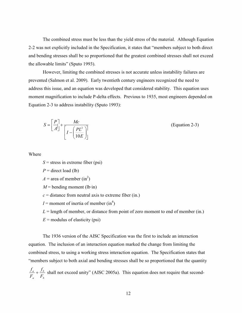
However, limiting the combined stresses is not accurate unless instability failures are
prevented (Salmon et al. 2009). Early twentieth century engineers recognized the need to
address this issue, and an equation was developed that considered stability. This equation uses
moment magnification to include P-delta effects. Previous to 1935, most engineers depended on
Equation 2-3 to address instability (Sputo 1993):
−
+
=
E
PLI
Mc
A
PS
10
2 (Equation 2-3)
Where
S = stress in extreme fiber (psi)
P = direct load (lb)
A = area of member (in2)
M = bending moment (lb·in)
c = distance from neutral axis to extreme fiber (in.)
I = moment of inertia of member (in4)
L = length of member, or distance from point of zero moment to end of member (in.)
E = modulus of elasticity (psi)
The 1936 version of the AISC Specification was the first to include an interaction
equation. The inclusion of an interaction equation marked the change from limiting the
combined stress, to using a working stress interaction equation. The Specification states that
“members subject to both axial and bending stresses shall be so proportioned that the quantity
b
b
a
a
F
f
F
f+ shall not exceed unity” (AISC 2005a). This equation does not require that second-

13
order effects be considered, but was acceptable for the working stresses of the time. The
allowable compression stress, 0.51Fy, and allowable bending stress, 0.60Fy, were low enough
that second-order effects remained below the limit because there is enough extra capacity (Sputo
1993).
After extensive research into the ultimate strength of steel, new stability and strength
equations were developed for beam-columns. In the 1961 revision of the Specification the
straight-line interaction equation was replaced by Equations 2-4 and 2-5. These equations more
accurately represent a beam-column’s behavior because they consider both strength and stability
(Sputo 1993):
0.1
1'
≤
−
+
b
e
a
bm
a
a
FF
f
fC
F
f (Equation 2-4)
0.160.0
≤+b
b
y
a
F
f
F
f (Equation 2-5)
Equation 2-4 addresses stability and second-order moments caused by P-delta effects. Equation
2-5 considers the strength of the member, and lateral-torsional buckling. Fb must be adjusted for
effective length. This Specification allowed the previous straight-line interaction equation to be
used when the axial stress did not exceed fifteen percent of the yield stress. This allowance is
permitted because P-delta effects are small when axial forces are low (Sputo 1993). However,
these equations are complicated, and apply only to 33 ksi and 36 ksi steel. They also only
address bending in one plane, as the variable Cm indicates that there is no lateral translation of
the frame.
AISC simplified Equations 2-4 and 2-5 and broadened their material scope for the 1970
specification. Equation 2-6 and 2-7:
0.1
1
≤
−
+
m
e
m
crM
P
P
C
P
P (Equation 2-6)

14
0.118.1
≤+py M
M
P
P (Equation 2-7)
use plastic design to compare factored loads to a member’s ultimate strength (Sputo 1993).
Plastic design indicates that structures experience equilibrium at or below the yield stress of the
steel (AISC 2005a). For short members the strength equation, Equation 2-7, controls, and for
long members the stability equation, Equation 2-6, controls. For intermediate length members
the magnitudes of the forces determine which equation controls. If a high bending moment is
applied to an intermediate length member, Equation 2-7 controls for strength, but if high axial
loads are applied, then the Equation 2-6 controls for stability (Sohal et al. 1989).
The weakness of Equations 2-6 and 2-7 is the transition between them. As the length of a
member gets smaller, as seen in Figure 2-5(b), the stability equation does not decrease to the
strength equation, and results in a jump between the two curves (Duan and Chen 1989). This
transition between long and short members causes Equation 2-7 to be truncated by Equation 2-6,
as indicated in Figure 2-5(a) and (b). This cut-off causes an inconsistency that indicates that the
interaction equations are unconservative in the transition region, or too conservative everywhere
else (Sohal et al. 1989).

15
Figure 2-5. Strength and Stability Check for Member: (a)KL/r = constant; (b) Constant
Moment and Varying Slenderness (With permission from ASCE, Fig. 1 (Sohal et al. 1989))
These equations remained in effect until the 1986 Specification introduced the Load and
Resistance Factor Design (LRFD) equations. The equations that appear in the current thirteenth
edition of the Specification (Eq. H1-1a and H1-1b) are an updated version of the 1986 LRFD
equations (AISC 2005a). These equations:

16
For 2.0≥c
r
P
P 0.1
9
8≤
++
cy
ry
cx
rx
c
r
M
M
M
M
P
P (Equation 2-8)
For 2.0<c
r
P
P 0.1
2≤
++
cy
ry
cx
rx
c
r
M
M
M
M
P
P (Equation 2-9)
are based on the inelastic behavior of steel (Sputo 1993). The available flexural strength, Mc, is
determined using Chapter F of the Specification, and addresses the limit states of yielding,
lateral-torsional buckling, and local buckling. The available axial strength, Pc, is determined in
Chapter E of the Specification and addresses column slenderness, buckling, and torsional and
flexural-torsional buckling. Secondary P-delta effects are taken into account in the Pr and Mr
terms (AISC 2005a). These equations allow the engineer to select which method of second-
order analysis they would prefer to use (Sputo 1993).
These equations can also be used for members with biaxial bending (AISC 2005a). They
simplify design by including both strength and stability in one equation, so that the designer
needs to use only one equation, instead of two (Sputo 1993). Also, having only one equation
eliminates the discontinuity between the stability and strength equations caused by the previous
set of equations (Duan and Chen 1989). These equations were obtained by curve-fitting into data
mainly for I-shapes bent about the strong axis, although they are applied to all shapes and biaxial
bending (Sohal et al. 1989). For short beam-columns under weak-axis bending and axial
loading, these equations generate an overly conservative design (Duan and Chen 1989).

17
3 Secondary Stresses
There are two types of stresses within a truss, primary and secondary. Primary stresses
are purely axial stresses induced in a pin-jointed ideal truss (Norris et al. 1976; Brockenbrough
and Merritt 1999). Secondary stresses are caused by forces other than axial, including bending,
shear and torsion (Grimm 1908). Secondary stresses are not only due to second-order effects.
Although some secondary stresses do originate from P-delta effects, a majority of secondary
stresses are caused by first-order bending moment that is overlooked in ideal truss analysis
(Brockenbrough and Merritt 1999). These first order moments are produced by the
characteristics of an actual truss that are ignored in the formation of an ideal truss (Charlton
1982). The distinguishing characteristics that cause secondary stresses are connection
eccentricity, traverse loading, and joint rigidity (Norris et al. 1976; Brockenbrough and Merritt
1999).
3.1 Connection Eccentricity
Connections are eccentric when the centers of gravity of the members and connecting
elements do not intersect at one point. In trusses, forces are applied along these centers of
gravity. Eccentricities will produce a moment because the forces are applied away from the
connection center. These moments, and their resulting secondary stresses, are easily minimized
by detailing joints to mimic the behavior of an ideal truss. By ensuring that the centers of gravity
of the elements and connectors are concentric, ideal pinned connections are simulated
(Brockenbrough and Merritt 1999). Detailing concentric connections minimize moments that
cause secondary stresses because the member forces act along the intersecting lines of action of
the centers of gravity (Timoshenko and Young 1945; Norris et al. 1976). Connection
eccentricities caused by imperfections in construction are deemed immaterial because design
procedures and safety factors will accommodate these small flaws (Korol et al. 1986).
If a truss design does not allow for concentric joint connections, due to limiting
geometries, secondary stresses caused by the connection eccentricity need to be considered.
However, this occurrence only needs to be regarded in specific situations (Korol et al. 1986).
These cases occur when member or connection geometries prohibit the alignment of all centers
18
of gravity. In this situation, the moment, caused by the axial force applied at the eccentricity,
must be regarded as an external moment and included in the analysis (Timoshenko and Young
1945).
3.2 Transverse Loading
Transverse loads are the loads applied to a truss, along the members, between joints.
There is always some transverse loading applied to truss members, from self weight. If the
members are pinned, any bending by this loading is confined to its member, as pinned joints
cannot transfer moment. However, if the members are continuous, most often in the chords, then
the panel points are rigid, and capable of transferring bending moment to adjacent members
(Vinnakota 2006).
Although self weight is a transverse load, it is typically collected at the panel points to
eliminate flexural effects and simplify analysis (Timoshenko and Young 1945). However, since
trusses are often used in long-span applications, the self weight can become considerable. A
substantial self weight can greatly contribute to the total stress, and should be considered in truss
design (Brockenbrough and Merritt 1999).
Transverse loading can also occur due to superimposed loads along the length of the
chords. These loads become significant to secondary stresses when there is a large load along
the length of the member. Sometimes a purlin or joist must frame into a truss between panel
points, inducing a point load along the span of the chord. Also, a truss chord can support a
uniform load from roof deck that will cause bending (Segui 2007). However, these
circumstances are rare, and are addressed only in specific situations. A typical procedure to
address these transverse loads is to accumulate the loads at the joints, and analyze the ideal truss
under this loading. After determining the axial forces in the members, the chords that experience
transverse loading should be designed for the combined axial and bending forces (Ambrose
1994). This procedure is satisfactory for small transverse loading and pinned joints, however,
Segui (2007) recommends this three step procedure, be used to analyze superimposed transverse
loads on continuous chords:
1. Calculate the fixed-end moments for the continuous compression chord, based on the
load pattern.
19
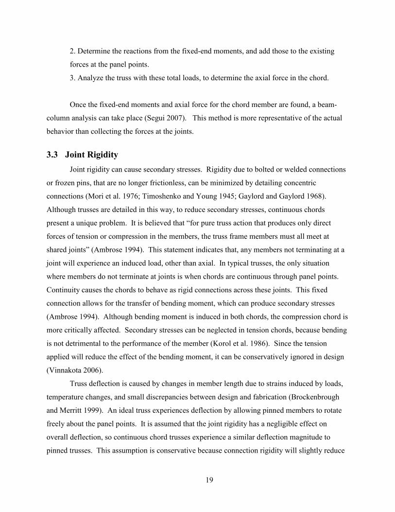
2. Determine the reactions from the fixed-end moments, and add those to the existing
forces at the panel points.
3. Analyze the truss with these total loads, to determine the axial force in the chord.
Once the fixed-end moments and axial force for the chord member are found, a beam-
column analysis can take place (Segui 2007). This method is more representative of the actual
behavior than collecting the forces at the joints.
3.3 Joint Rigidity
Joint rigidity can cause secondary stresses. Rigidity due to bolted or welded connections
or frozen pins, that are no longer frictionless, can be minimized by detailing concentric
connections (Mori et al. 1976; Timoshenko and Young 1945; Gaylord and Gaylord 1968).
Although trusses are detailed in this way, to reduce secondary stresses, continuous chords
present a unique problem. It is believed that “for pure truss action that produces only direct
forces of tension or compression in the members, the truss frame members must all meet at
shared joints” (Ambrose 1994). This statement indicates that, any members not terminating at a
joint will experience an induced load, other than axial. In typical trusses, the only situation
where members do not terminate at joints is when chords are continuous through panel points.
Continuity causes the chords to behave as rigid connections across these joints. This fixed
connection allows for the transfer of bending moment, which can produce secondary stresses
(Ambrose 1994). Although bending moment is induced in both chords, the compression chord is
more critically affected. Secondary stresses can be neglected in tension chords, because bending
is not detrimental to the performance of the member (Korol et al. 1986). Since the tension
applied will reduce the effect of the bending moment, it can be conservatively ignored in design
(Vinnakota 2006).
Truss deflection is caused by changes in member length due to strains induced by loads,
temperature changes, and small discrepancies between design and fabrication (Brockenbrough
and Merritt 1999). An ideal truss experiences deflection by allowing pinned members to rotate
freely about the panel points. It is assumed that the joint rigidity has a negligible effect on
overall deflection, so continuous chord trusses experience a similar deflection magnitude to
pinned trusses. This assumption is conservative because connection rigidity will slightly reduce

20
deflection (Charlton 1982). In order for a truss with continuous chords to achieve a deflection
similar in magnitude to a pinned chord truss, the members must rotate relative to each other, in
the same manner as they would in an ideal truss. At a rigid, continuous connection, a moment is
induced at the fixed end of each member, to achieve this rotation (Grimm 1908; Timoshenko and
Young 1945). This fixed end moment that allows chord deformation for overall truss deflection
is the principal cause of secondary stresses (Brockenbrough and Merritt 1999). The chords are
therefore subjected to axial forces and a bending moment (Norris et al. 1976).
These secondary stresses can be avoided by using spliced chords with no continuity
across panel points. However, most trusses are constructed with continuous chords to reduce the
number of members and connections. Truss fabrication cost is driven by ease of assembly,
which is increased by reduction in the number of connections. Because reducing the number of
connections is desirable, continuous chords are usually incorporated, and secondary stresses will
be present (Ambrose 1994).
3.4 History of Secondary Stresses
The regard for secondary stresses has evolved as engineers gain understanding of truss
behavior. Secondary stresses were given little attention until the late 1800s (Charlton 1982;
Timoshenko 1953). Although engineers considered them in design, no formal research had been
done on the subject. In 1877 Professor Asimont of Munich Polytechnic coined the phrase
“secondary stress” and proposed that a thorough analysis be performed on trusses with rigid
joints (Charlton 1982; Grimm 1908).
3.4.1 Manderla’s Method
In 1880, under the urging of Professor Asimont, Heinrich Manderla was the first to
explore and publish an extensive analysis of secondary stresses (Grimm 1908; Korol et al. 1986).
He demonstrated that, in trusses with rigid joints, displacement and rotation of joints must be
considered (Timoshenko 1953). In his analysis Manderla assumed that all deformations occur
within the plane of the truss, eliminating torsion, and that all loads are applied at panel points
(Grimm 1908). He also assumed that the joints deflected the same amount in an ideal truss and
an actual truss. Because the difference in deflection between an ideal truss and an actual truss is
small, this assumption is valid. Also, because connection rigidity will slightly reduce
deflections, the assumption is conservative (Charlton 1982). Manderla then formulated a

21
relationship between the unknown moment and the angle of rotation of the member. This
relationship was used to solve for the unknown moment, and then find the secondary stresses
(Grimm 1908).
The equations Manderla derived, although accurate, were complicated and time-
consuming. They required simplification for practical engineering application (Timoshenko
1953). His method considers second-order P-delta effects, and lever-arm changes due to axial
deformation of the members (Grimm 1908). Subsequent methods aimed to simplify these
computations by assuming these effects to be negligible.
3.4.2 Müller-Breslau’s Method
Heinrich Müller-Breslau’s method is simplified from Manderla’s method by neglecting
the influence of second-order P-delta effects (Grimm 1908). He reasoned that the P-delta effects
are negligible because a truss chord must be significantly stiff to produce critical secondary
stresses. If the member is stiff, the deflections causing P-delta effects will be minimal (Charlton
1982). Therefore, Müller-Breslau’s method becomes more accurate with increasing stiffness of
the member, as the secondary stresses become more critical (Grimm 1908).
Müller-Breslau treated the joints differently. He assumed that, as the joint rotated, the
members did not change angle in relation to each other (Charlton 1982). He formulated a
relationship between the angle of rotation and the unknown moment, length and moment of
inertia of the member. Once this relationship is established, the unknown moment can be solved
(Grimm 1908).
3.4.3 Mohr’s Method
In 1892, Otto Mohr simplified Manderla’s complicated analysis with a method that
gained widespread use (Timoshenko and Young 1945). Mohr’s method neglects P-delta effects,
just as Müller-Breslau’s method did, but also neglects the changes in the lever-arm due to axial
deformations. Mohr replaces the unknown end moments with angles that relate to these
moments. By doing this, he reduced the number of unknowns in his formulas. Rigid
connections cause member angles on either side of the joint to be equal. He formed equilibrium
equations where the sum of moments at each joint is zero. Since each joint only has one
unknown angle, the number of equations equals the number of unknowns and the equations can

22
be solved. Once these angles are determined, they can be used to find the end moments of each
member, and the secondary stresses (Grimm 1908).
3.4.4 Slope-Deflection Method
The work of Manderla and Mohr, through simplifications and assumptions, evolved into
the slope-deflection method that is still used today. The slope-deflection method relates
unknown rotations and deflections of a member to the load applied (Hibbeler 2006). This
method assumes that truss displacements are unaffected by joint stiffness, and therefore, can be
found using analytical or graphical analysis of an ideal truss (Charlton 1982). Then, the angle of
rotation of a specific member can be found by trigonometry, using the joint displacements. The
fixed-end moment necessary to cause this angle of rotation is found, and is used in beam-column
analysis of the members (Timoshenko and Young 1945).
Many other engineers contributed to the analysis of secondary stresses in trusses. In
1879, a year before Manderla’s method was published, Engesser published a simpler solution in
which the rigidity of web member connections was neglected, and only chord rigidity was
considered. This solution indicates that the most influential rigidities are due to continuous
chords, rather than connections, where the effects of rigidity can be minimized. Landsberg then
contributed a graphical solution using assumptions similar to Engesser (Charlton 1982).
Many books were published on the subject at this time. Winkler published a book in
1881 that contained “an extensive and impressive treatment of secondary stresses in bridge
trusses.” Engesser published a book in 1892 that was adopted as the standard reference for
secondary stresses (Charlton 1982).
3.5 Secondary Stress Consideration
When a bending moment is induced into a compression member, part of the strength of
the member is used to resist this moment, leaving less strength to resist the axial forces (Chen
and Lui 1985). Engineers must determine if secondary stresses are minor enough to neglect, or if
they are going to produce stresses large enough to affect the truss design. Designing a truss
using ideal assumptions is conservative for the overall truss structure because replacing pinned
connections with rigid connections results in “a stiffer structure with a strength at least equal to
(and usually greater than) that calculated for the same structure with hinges” (ASCE 1971).
However, the members need to be examined individually due to the induced moment, to ensure

23
that they are independently adequate to support their forces. If a designer obtains axial forces
from a secondary stress analysis that includes bending moment, he or she must also include
flexural effects in the design, because they affect the magnitude of axial forces (Nair 1988).
A more complicated analysis is required to determine secondary stresses, but they are
usually regarded as negligible (Nair 1988). By the early 1900s enough information was
discovered to indicate that “secondary bending stresses due to continuity are unlikely to affect
the ultimate capacity of ductile truss members.” This approximation was adopted due to the
tedious nature of secondary stress analysis, which was too time-consuming before computer
analyses were available (Korol et al. 1986). Typically, the stresses computed under the
assumption of an ideal truss are adequate for practical design (Norris et al. 1976). However, in
certain situations, with stiff or stocky members, secondary stresses may become critical and need
to be considered. Guidelines have been developed to determine if secondary stresses are critical
enough to investigate.
3.5.1 Empirical Evaluation Criteria
Many empirical limits have been set to determine if secondary stresses should be
investigated. By proportioning member properties, limits can be set that dictate whether
secondary stresses are going to be significant to the truss design. These property ratios are a
numerical way to represent the stiffness of a member relative to its length, as this stockiness is
directly related to the magnitude of secondary stresses (Gaylord and Gaylord 1968; Ambrose
1994).
These rules of thumb can be found in truss design literature. A ratio of length of the
member, L, over radius of gyration, r, less than fifty indicates that the member is sufficiently stiff
to cause significant secondary stresses, which need to be investigated. Alternatively, if the
moment of inertia, I, over the length of the member, L, is larger than fifty percent, the same
conclusion can be drawn (Ambrose 1994).
As these ratios indicate, stiffer members produce higher secondary stresses. Long,
slender members require less moment to achieve rotation, so they produce fewer secondary
stresses. Most trusses have long, slender members and fall into this category. When a designer
considers secondary stresses in truss design, they must also consider the effect that these stresses
have on the axial forces (Ambrose 1994). This process can become complicated, so engineers

24
prefer to keep secondary stresses at a level that is small enough to neglect. By meeting the above
conditions secondary stresses are assumed to be low. Since a certain amount of reserve capacity
exists in current design methods, small amounts of secondary stresses can be accounted for in
this extra capacity. Another guideline states that secondary stresses that do not exceed twenty
percent of the primary stresses can be safely ignored in design (Korol et al. 1986). However,
when joint rigidities reach higher levels, as in a continuous chord, secondary stresses should be
addressed (Ambrose 1994).
3.5.2 Code Requirements
Although it is common practice to ignore secondary effects in truss members, some
specifications require that these effects be considered (Segui 2007). The AISC Specification
does not address this issue, but other specifications, where secondary stresses are very
influential, address their consideration. The American Association of State Highway and
Transportation Officials (AASHTO) LRFD Specification states that “secondary stresses due to
truss distortion or floorbeam deflection need not be considered in any member whose width
measured parallel to the plane of distortion is less than one-tenth of its length” (AASHTO 2004).
Therefore a truss member with a depth less than ten percent its length, will typically produce
secondary stresses below twenty-five percent of primary stresses (Gaylord and Gaylord 1968).
This constraint is a quick check to determine if secondary stresses need to be more closely
investigated. The AASHTO-LRFD Specification also makes concessions for other causes of
secondary stresses. It indicates that truss “design and details shall be such that secondary
stresses will be as small as practicable.” This requirement implies that concentric connections
and framing into joints should be included to reduce secondary stresses due to eccentricities and
transverse loading. Also, the AASHTO-LRFD Specification indicates that stresses due to
connection eccentricities and dead load should be considered (AASHTO 2004).
The North American Standard For Cold-Formed Steel Framing – Truss Design, AISI
S214-07, also specifies when secondary stress must be considered. It indicates that secondary
stresses in continuous chords are significant in cold-formed steel trusses, and must be
investigated. It specifies that truss analysis should be done under the assumption that “chord
members are continuous, except members are assumed to have pinned connections at the heel,
pitch breaks, and chord splices.” Also, web members are assumed to be pinned, indicating that

25
secondary stresses are only significant in the chords. This specification outlines how secondary
stresses should be treated in the compression and tension chord, specifically. It states that the
chords must be evaluated separately for axial load, bending load, and combined axial and
bending loads (AISI 2007).
3.6 Secondary Stress Analysis
To consider secondary stresses in design, the truss must undergo a more rigorous
analysis. The joint rigidities can be accounted for by analyzing the truss as a frame, with joints
that are capable of transferring flexural and shear forces, as well as axial (Nair 1988; Norris et al.
1976). Magnitudes of moments and axial loads in trusses can be found using the stiffness
method, as most computer programs do (Segui 2007). This method, however, is complex
without computer analysis, and typically a simpler method will suffice, such as slope-deflection.
If an entire frame analysis is not desired, the process can be simplified by an ideal truss
analysis followed by the individual examination of the chords as beam-columns (Thomas and
Brown 1975). Using pin-jointed solutions of trusses that have continuous joints generates a
solution that is five to seven percent lower than a more sophisticated frame analysis (Korol et al.
1986). Typically, a result that is within five percent of the actual behavior of a truss in the beam-
column interaction equation is considered adequate. This constraint is demonstrated by the
accuracy of the effective length method for second-order analysis. This method was developed
under the guidelines that it would be no more than five percent unconservative when compared
to actual second-order analysis (Salmon et al. 2009). This indicates that, for beam-column
design, an interaction value of five percent over unity is acceptable for most designs. Since this
method, with its inaccuracies, is accepted by the AISC Specification, a five percent increase in
interaction value, due to secondary stresses, is considered acceptable in this report.

26
4 Analytic Studies of Secondary Stresses in Steel Trusses with
Chord Continuity
As discussed previously, secondary moments, caused by secondary stresses, are induced
in truss members with rigid connections. These moments increase as the connection rigidity
increases (Machaly 1984). The most rigid connection is one in which a member is continuous
through the panel point. This maximum rigidity induces the greatest secondary moment and
thus, the most secondary stresses. The secondary stresses addressed in these studies are due to
joint rigidity, caused by chord continuity, which produces a majority of secondary stresses in
truss members (Brockenbrough and Merritt 1999). Continuous chords prohibit the chord
members from deforming relative to each other, which causes moment transfer and induces shear
and bending stresses (Norris et al. 1976). For construction purposes, it is common to have chord
members that are continuous through one or more panel points (Ambrose 1994). These studies
aim to determine the effect these secondary stresses have on the truss chord members.
Steel trusses are analyzed in these studies using matrix methods of the commercial
analysis software, RISA 3D (RISA 2007), to verify the effects of secondary stresses on the chord
members. The focus is on the compression chord, as it can be seriously affected by secondary
bending stresses. Tension chords are insignificantly influenced by bending moment, and
therefore are disregarded in these studies (Korol et al. 1986). Only the most critical member in
the chord, the one that yields the highest interaction value, is examined. Because most of the
required strength for a compression chord is due to axial loading, the most critical member is the
one with the highest axial compressive force. This member has the highest interaction value, and
is located on either side of the midpoint of the truss. The critical members are shown in Figure
4-1:

27
Figure 4-1. Critical Chord Members for Analysis
Load and Resistance Factor Design (LRFD) is used in these studies. P-delta effects are
included in the solution in RISA 3D, as this provides a more accurate result, however, it is only a
small contributor to secondary stresses. Deflection limits were not considered. To model the
compression chord members as continuous they are input into RISA 3D as separate members,
between panel point, with fixed end connections. This modeling technique ensures that the
unbraced length for each chord member is the length of one panel, which reflects the true
unbraced length of an actual truss chord. Web members are pin connected in all models using
Engesser’s assumption (Charlton 1982). This configuration was applicable because only chord
continuity was being examined as having significant rigidity, so the rigidity of other truss
connections is disregarded. A semirigid web member connection (bolts or welds) would have a
small affect on the joint rigidity, but is ignored in these studies. The additional stiffness may
increase secondary stresses slightly. The trusses are modeled with a pinned support at one end,
and a roller at the other. This arrangement allows for the joints to rotate as the truss deforms
under loading. It also allows for expansion and contraction of the truss members (Vinnakota
2006).
This study focuses on single-plane trusses that have members that are symmetric about
this plane, and loads that are applied in this plane. Under these conditions, any secondary
stresses will be induced within this plane, and there are no torsional effects (Timoshenko and
Young 1945). Self weight is typically neglected in the manual analysis of trusses, so it was
initially ignored in these studies. Neglecting self weight, a transverse load, ensures that joint
rigidity is the only cause of secondary stresses. Self weight is then included, in order to create a
more realistic model, and determine how it affects the results. The trusses are developed
assuming that framing is supported at truss panel points. This framing ensures that the
compression chord is braced at the panel points. These locations are the only points where the

28
loading is applied. This configuration is typical for most trusses. The tension chord would still
only be braced at the truss ends, but it is not considered in these studies. The trusses are assumed
to be spaced twenty feet apart for determination of loading.
The goal of these studies is to determine how secondary stresses induced by chord
continuity increase the required strength of the chord members. Because inducing secondary
moments into a truss chord cause the members to become beam-columns, rather than purely
axial members, the interaction equation for beam-columns is used to examine the effects of
secondary stresses. These effects were gauged by the result of the interaction equation for each
chord. The interaction value was determined using Equation 2-8 (Eq. H1-1a) from the
Specification (AISC 2005a). The interaction values are compared between the pinned and
continuous chord members to determine the increase in flexural effects, caused by secondary
stresses. An increase in interaction value in trusses with continuous chords indicates the
presence of secondary stresses because these stresses increase the required flexural strength
which increases the interaction value. This process is conducted neglecting member self weight,
then again including self weight.
Another goal of these studies is to determine whether the evaluation criteria addressed in
Section 2.5 are appropriate for secondary stress consideration. Also, these studies aim to
develop new evaluation criteria that more closely represent the impact of secondary stresses, and
dictate whether a secondary stress analysis is necessary. Because manual secondary stress
analysis is time consuming, especially compared to ideal truss analysis, it should only be
undertaken when necessary. Criteria can be used to determine whether secondary analysis is
worth considering, so that it is only carried out when secondary stresses critically affect the
design. Three different studies were performed, to determine the effects of member and truss
properties on secondary stresses. The first study examines the effect of member stiffness on
secondary stresses; the second study examines the effect of depth to span ratio, while the third
study examines the effect of member efficiency.
4.1 Chord Size Study
The Chord Size Study was conducted to determine the impact of chord stiffness on the
increase in secondary stresses. Compression chords of several depths were chosen based on
ideal truss analysis, which met the required strength, to determine the influence of stiffness on

29
the magnitude of secondary stresses. Each truss was modeled in three different configurations.
The first configuration is a pin connected ideal truss. The second configuration is a truss with
fixed chords, to represent one continuous chord across the entire truss. The third configuration is
a truss with a pinned connection at the midspan, which represents a splice for construction and
transportation purposes. This splice is modeled as a pinned connection, because the chords are
not continuous through the splice. It was placed at a panel point, as is common in WT chord
truss construction (Brockenbrough and Merritt 1999).
4.1.1 Truss Geometry
The truss geometry was chosen to represent a common truss of typical layout, as seen in
Figure 4-2:
Figure 4-2. Pratt Truss Geometry and Loading
The truss is a 100 feet long parallel chord Pratt truss. Parallel chord Pratt trusses are
advantageous because the longer web members are in tension while the shorter web members are
in compression (Ambrose 1994). Therefore, smaller web members can be used to prevent
compressive buckling failures. Since compression member size is dependant on length, while
tension member size is not, having shorter compression members allows for smaller member
sizes. These smaller members save weight and cost when constructing a truss (Vinnakota 2006).
Pratt trusses are typically used in spans of up to 200 feet (Hibbeler 2006). The 100 foot truss has
a span to depth ratio of 10:1, with a depth of ten feet. The truss is comprised of ten panels, each
of ten feet in length. With ten foot by ten foot panels, the diagonals are sloped at 45 degrees,
which meets the preferred 40 to 60 degrees recommended for economic design (Brockenbrough
and Merritt 1999; Hibbeler 2006).

30
WT sections of A992 steel (Fy = 50 ksi) are used for the truss chords, with double angle
web members of A36 steel (Fy = 36 ksi). This arrangement is common and advantageous. The
double angle webs can be welded directly to the stem of the tee shape, eliminating the need for
gusset plates (Segui 2007).
4.1.2 Truss Loading and Member Selection
The roof dead load applied to the truss was fifteen pounds per square foot, which is
typical for roofs. The roof live load was twenty pounds per square foot, which is the maximum
roof live load (ICC 2006). Using LRFD, the factored load applied to each panel point is ten kips.
This ten kip force is applied at each panel point, except for the end panel points, where half of
the tributary area exists, and therefore, only a five kip force is applied. See Appendix A for the
calculations to attain this loading.
Once the geometry and load pattern were determined, the truss member sizes are
selected. These sizes are chosen based on the ideal truss with pinned connections, which is a
common method of design. The self weight is neglected in these calculations. First, the
reactions are found at the supports, from the superimposed loads. Then, the method of joints is
carried out manually, to determine the axial forces in each truss member. The members are
selected based on these required strengths, using the compression (Tbs. 4-7 and 4-8) and tension
(Tbs. 5-3 and 5-8) tables from the thirteenth edition of the AISC Specification (AISC 2005a).
Many different sizes of compression chord are studied, with differing stiffness, to determine the
effect on secondary stresses. The depth of compression chord ranges from WT4 to WT12. The
WT4 was the shallowest member chosen because a shallower WT makes achieving the web
member connection very difficult. The WT12 was the deepest section selected because deeper
members became heavy and would not practically be chosen for design. The most economical,
lightest section of each depth that meets the required strength is chosen for examination. See
Appendix A for method of joints calculations and member selection.
4.1.3 Results of Analysis
Once all properties of the truss were determined, this information is input into RISA 3D
(RISA 2007). Each truss with a different compression chord member size is modeled in the
three different configurations of fully pinned, fully fixed, and fixed with a pinned splice at the
midpoint. The member required strengths can be used to indicate the effect of secondary

31
stresses. Tables 4-1 and 4-2 show the required compressive strength, Pu, and required flexural
strength, Mu, in the critical chord members, with and without self weight:
Table 4-1. Required Compressive Strength and Required Flexural Strength in Critical
Truss Chord Members Neglecting Self Weight
Table 4-2. Required Compressive Strength and Required Flexural Strength in Critical
Truss Chord Members Including Self Weight
Once the member required strengths were determined, they were manually input into the
interaction equation (Eq. 2-8) to determine the interaction value for each truss chord. Table 4-3
shows the interaction values for each compression chord with and without self weight:

32
Table 4-3. Interaction Values for Critical Compression Chord Member
Once the interaction values are determined, the percent increases in the continuous and
spliced truss chord interaction values, relative to the pinned truss chord interaction value, are
determined. The pinned chord truss model is used as the basis of comparison because it is
representative of how trusses are manually designed, and has no induced secondary stresses
when self weight is neglected. The percent increases are shown in Table 4-4:
Table 4-4. Percent Increase in Interaction Value Relative to Ideal Truss
Once the percent increases were found the results are compared to the evaluation criteria,
as discussed in Section 3.5, to determine if these criteria can predict the severity of secondary
stresses. These criteria are used to indicate whether secondary stress analysis should be

33
considered for the truss. Table 4-5 shows the percent increases and the evaluation criteria found
in various codes and literature:
Table 4-5. Evaluation Criteria to Determine Secondary Stress Consideration
Percent increases over five percent are shaded, to indicate a significant increase, which
should be studied further, as discussed in Section 3.6. The evaluation criteria are shaded if they
exceed the limits set by the codes and literature.
New criteria are then developed and tested to determine whether more accurate
guidelines can be set for the consideration of secondary stresses. Since secondary stresses are
caused by truss deflection and chord stiffness, criteria are chosen that represent these properties.
These criteria include the elastic and plastic section moduli of the chord member, and the
moment of inertia of the entire truss. The elastic section modulus criterion is examined because
it is indicative of the stiffness of the member, as it is dependent on the chord’s moment of inertia
(sx = I/c) (Segui 2007). The plastic section modulus, Z, is examined because it is related to plastic
moment capacity (MP = FyZx) (AISC 2005a). The moment of inertia of the truss as a whole is
examined because it affects a truss’ overall deflection, which causes the member rotation that
induces secondary stresses at the rigid joints. The moment of inertia for the entire truss is
calculated about the center of gravity of the top and bottom chords. The web members are
ignored. See Appendix B for truss moment of inertia calculations.
Because the evaluation criteria found in codes and literature relate to the member length,
this parameter is used in these new criteria. An upper limit of twenty is chosen for the elastic
section modulus criterion, because, as the stiffness increases, indicating an increase in secondary
stresses, the L/sx values decrease. A lower limit of 350 is chosen for the truss moment of inertia

34
criterion, since an increase in moment of inertia, which causes IT/L to increase, indicates a
decrease in deflection, and a decrease in secondary stress. An upper limit of fifteen is designated
for the plastic section modulus criterion because this value will decrease as stiffness increases.
These values are chosen based on the results for the truss including self weight, as this is a more
realistic model. Since stiffness and deflection induce secondary stresses, these criteria may
correlate to the increase in interaction values. Table 4-6 shows the percent increases with the
results of the new criteria. Values exceeding the limits are shaded.
Table 4-6. New Evaluation Criteria to Determine Secondary Stress Consideration
4.1.4 Evaluation of Results
The results of this study are examined to determine how secondary stresses affect truss
compression chords of varying stiffness. First, the required strengths and resulting interaction
values are studied to determine the effect of secondary stresses. Then evaluation criteria are
studied to establish methods of predicting the necessity of secondary stress analysis.
4.1.4.1 Indications of Secondary Stresses
The influence of secondary stresses on member required strengths is observed in Tables
4-1 and 4-2. With the exception of the WT4x29, which has a greater moment of inertia than the
WT5x19.5, the chords are arranged in increasing order of stiffness in the tables. Table 4-1
shows the impact of secondary stresses in trusses where self weight is neglected. In these
trusses, the required compressive strengths are approximately equal in the pinned, continuous
and spliced chord configurations. As expected, there is no required flexural strength in the

35
pinned truss chord, when self weight is neglected, because pinned connections are incapable of
producing secondary stresses and without self weight, there are no transverse loads. The
required flexural strength, however, increases as the stiffness of the compression chord member
increases, in the models with chord continuity, except for the WT4x29. This increase indicates
that secondary stresses are being induced, since the superimposed loading for each truss does not
change. The required flexural strength in the spliced chord is less than the required flexural
strength in the continuous chord truss for each chord member size. This difference indicates that
the pinned connection splice on one side of the critical chord member causes the induced
secondary stresses to be lower, as only one end has a rigid connection that produces secondary
stresses.
Table 4-2 shows the required strengths for the truss analysis that included self weight.
The results are similar to the models neglecting self weight. The required axial strengths,
although higher when self weight is included, remain constant between all trusses. There is a
secondary moment induced in the pinned truss model due to the self weight of the chord
members. However, there is still a noticeable increase in the required flexural strength when
chord continuity is incorporated, due to secondary stresses. These required flexural stresses
increase with increasing member stiffness, and are smaller in the spliced truss than in the
continuous chord truss, much like the models without self weight.
The interaction values in Table 4-3 reflect the changes in member required strengths. As
the required flexural strength increases, so do the interaction values. Also, the interaction value
is less for the truss with the splice, than for the continuous chord truss because the required
flexural strengths of the members are smaller. Even though secondary stresses cause the
interaction value to increase, many chord members still meet unity, especially when self weight
is ignored. They still meet unity because the extra capacity in the members is enough to
accommodate the induced required flexural strength from secondary stresses. Although the
required flexural strengths increase as the member stiffness increases, the interaction values do
not follow this trend, due to the change in member design flexural strength. Therefore, required
flexural strengths alone cannot be used to dictate the consideration of secondary stresses.
4.1.4.2 Prediction of Secondary Stress Severity
Table 4-4 shows the increase in continuous and spliced truss chord interaction values
relative to the pin connected ideal truss values. As the percentages indicate, the increase in the

36
interaction value is smaller when self weight is considered, than when it is neglected. Including
self weight in the analysis adds more required strength to the chord. Because there is more
required strength applied to the chord initially, the addition of secondary stresses will account for
a smaller portion of the required strength. Also, the spliced chord truss has much less of an
increase in the interaction value. This effect is due to the smaller required flexural strengths
caused by the pinned splice at one end of the critical chord member, which does not create
secondary stresses. The spliced chord trusses never experience an interaction value increase
greater than five percent, which indicates that, for this study, this configuration is not critical for
secondary stress consideration.
These percent increases were then compared to the evaluation criteria in Table 4-5. A
five percent increase in the interaction equation value was used as the maximum increase before
secondary stresses should be considered, as discussed in Section 3-6. As the results show, the
length over radius of gyration criterion less than fifty corresponds most accurately, but is
unconservative, when using five percent as the limit. It is unconservative because it correctly
identifies only three out of the four critical truss chords when self weight is considered. The
moment of inertia of the chord member divided by the length, greater than 0.50, was slightly
more unconservative, identifying only two of the four critical members. The depth divided by
length criterion was the least reliable indicator; as it never exceeded 0.10, and therefore, gave no
indication that secondary stresses need to be evaluated. These criteria are most accurate when
examining the interaction values with self weight included.
New proposed evaluation criteria were developed and the results are presented in Table
4-6. The elastic section modulus criterion correlated closely to the increases in interaction
values. It was determined that for this truss, a length over elastic section modulus ratio less than
twenty indicates an increase in the interaction value greater than five percent when self weight is
included. A moment of inertia ratio equal to 350 was designated as the lower limit for this
criterion. This ratio correctly predicts the bottom four truss chords, but incorrectly identified two
truss chords as requiring secondary stress analysis. A plastic section modulus ratio of fifteen was
chosen as the maximum value for this evaluation criterion. This limit correctly identifies the
bottom four truss chords as needing secondary stress evaluation, when self weight is considered.

37
4.1.4.3 Continuous Chord Member Interaction Diagram
Once the data was collected an interaction diagram is formed for each truss member with
continuous chords, neglecting self weight. Self weight was neglected so that the only moments
in the chord members caused by secondary stresses induced by chord continuity. The Mu/ФMn
and Pu/ФPn values for the critical chord member are plotted on an interaction curve. Figure 4-3
shows this plot. As Figure 4-3 shows, the points are in the upper left corner of the graph. This
location indicates that the axial force consumes most of the member’s capacity. If no moment
was present, the points would be located on the y-axis, but the induced secondary moments shift
the interaction values slightly to the right. When these points shift to the right, they are more
likely to cross the line, which indicates the interaction value is exceeding unity, and the members
are undersized.
Figure 4-3. Critical Continuous Chord Member Interaction Diagram Neglecting Self
Weight

38
Figure 4-4 shows the same curve, focused on the area of the interaction values. From
Figure 4-4 it is noted that, as the secondary stresses increase with increasing stiffness, the
moments increase, and the points are further to the right and closer to, or exceeding, unity.
These graphs do not accurately represent the interaction equation (Eq. 2-8), because that
equation includes a factor of 8/9 on the moment contribution. However, it illustrates how the
interaction value is affected by increasing secondary stresses.
Figure 4-4. Critical Continuous Chord Member Interaction Diagram Neglecting Self
Weight
4.2 Depth to Span Ratio Study
After the initial study was performed additional trusses were examined. These trusses are
used to determine the effect of depth to span ratios on secondary stresses. These models are also
used to determine whether the evaluation criteria are valid for trusses of other geometries and
loading. The trusses used in these models were obtained from Brice Schmits’ study on the

39
Design Considerations for Parallel Chord One-Way Long-Span Steel Trusses (Schmits 2009).
Like the first study, these trusses were parallel chord Pratt trusses, with WT chords and double
angle webs. These trusses all had sixteen panels, unlike the ten in the initial study.
4.2.1 Results of Analysis
There were six trusses analyzed for each depth to span ratio. Depth to span ratios
included 1:12, 1:14, 1:16 and 1:18, as is common in modern trusses. The trusses were
distinguished by spans of 100, 150, or 200 feet, and by light or heavy loading. Trusses with light
loading had 20 psf dead load and 20 psf live load. Trusses with heavy loading had 20 psf dead
load and 40 psf live load (Schmits 2009). Each truss was analyzed with pinned chords and a
continuous chord. Although a 100 feet long truss with no splicing is rare, this configuration
causes the most extreme secondary stress effects for examination. A truss with a splice at the
midspan was not examined, since the first study suggests that it does not result in critical
secondary stresses, defined as an increase greater than five percent in the interaction value
(Section 4.1). The optimum compression chord size was selected by RISA 3D for each truss,
using the 1:16 depth to span ratio, continuous chord truss with self weight. The chord sizes were
kept constant for each different depth to span ratio. Therefore, only the changing depth to span
ratio will affect secondary stresses. The web member sizes are the same in each truss. The
trusses are analyzed neglecting and including self weight. The chord sizes and required strengths
in the critical chord members can be found in Table 4-7 for trusses without self weight and Table
4-8 for trusses with self weight. The depth to span ratios are shown in increasing order, as the
depth of the truss gets larger.

40
Table 4-7. Required Compressive Strength and Required Flexural Strength in Critical
Truss Chord Members Neglecting Self Weight

41
Table 4-8. Required Compressive Strength and Required Flexural Strength in Critical
Truss Chord Members Including Self Weight
The required strengths from Tables 4-7 and 4-8 are used to determine the interaction
value from Equation 2-8 for each truss. These results are shown in Table 4-9:

42
Table 4-9. Interaction Values in Critical Compression Chord Member
Once the interaction values were calculated, the percent increases between the pinned and
continuous chord trusses are determined. Table 4-10 shows these percent increases for each
truss configuration:

43
Table 4-10. Percent Increase of Interaction Values in Critical Chord Member
Once the percent increases in interaction value were calculated, the evaluation criteria are
applied, to determine if they predict when secondary stresses should be considered. The results
are shown in Table 4-11 with increases greater than five percent shaded, to indicate a necessity

44
for secondary stress analysis. The evaluation criteria are also shaded, when they exceed the
recommended limits in the codes and literature.
Table 4-11. Evaluation Criteria for Secondary Stress Consideration

45
The new proposed evaluation criteria are applied to these trusses as well, to determine
their effectiveness. These results are shown in Table 4-12. Values exceeding the limits are
shaded.
Table 4-12. New Evaluation Criteria for Secondary Stress Consideration

46
4.2.2 Evaluation of Results
The results of the Depth to Span Ratio Study are evaluated similar to the Chord Size
Study. The required strengths and interaction values indicate the impact of secondary stresses on
the critical chord member. The percent increases and evaluation criteria are used to determine
whether secondary stress analysis can be recommended for different trusses.
4.2.2.1 Indications of Secondary Stresses
Table 4-7 shows the required strengths for the trusses neglecting self weight. As the
depth of the truss increases for any given span, the critical chord member required compressive
strength, Pu, decreases. As the truss depth increases, the moment arm between the two chords
increases, so the axial force in each chord will be smaller to resist the bending moment applied to
the truss. Like the initial study, the required compressive strengths remain relatively unchanged
between the pinned and continuous chord models. The required flexural strength in each chord,
Mu, increases between the pinned and fixed models. No bending moment is expected in the
pinned models when self weight is neglected, because there are only axial forces in these
members with no continuity to induce secondary stresses. The presence of bending moment in
the continuous chord model without self weight indicates that secondary stresses are induced by
the joint rigidity, because chord continuity is the only variable between the models. The required
flexural strengths increase as the depth to span ratios decrease, like the required compressive
strengths. This increase in moment is due to the decrease in the truss’ moment of inertia. A
decreasing moment of inertia causes the deflection to increase. An increasing deflection will
require more member rotation, and result in increased secondary stresses, which produce the
moment in the compression chord members.
The results in Table 4-8 for the trusses that include self weight are very similar to those
of the trusses that do not include self weight. The required compressive strengths remain
unchanged between the pinned and continuous chord trusses. The difference between the models
that include and those that exclude self weight is in the required flexural strength present in the
critical chord member. The self weight induces a small bending moment, in both the pinned and
continuous chord truss. Like the trusses that neglected self-weight, the required flexural strength
increases when the chords are made continuous, due to induced secondary stresses.

47
The interaction values in Table 4-9 resulting from the application of Equation 2-8
increase for each truss, as the depth to span ratio decreases. This increase occurs due to the
increase in required compressive and flexural strengths as the depth to span ratio decreases. The
member sizes do not change, so the chord’s capacity remains constant. Since the capacity
remains constant, the interaction value increases, as the required strengths of the members
increase. Similar to the Chord Size Study, the interaction value is higher in the continuous chord
truss than the ideal pinned truss due to the induced secondary moments. Also, the interaction
values are higher when self weight is considered, due to the increased required strength of the
member.
4.2.2.2 Prediction of Secondary Stress Severity
Table 4-10 shows the percent increase in interaction values, relative to the ideal pinned
truss. The increase in the interaction value becomes larger as the depth to span ratio decreases,
regardless of self weight considerations. Like the first study, the increase is smaller when self
weight is included in the analysis because secondary stresses comprise a smaller amount of the
total required strength of the member.
Table 4-11 indicates that, as in the initial study, the radius of gyration criterion less than
fifty matches most accurately with an increase in the interaction value of five percent or more.
When self weight is considered this criterion correctly identifies all but two trusses that should
be analyzed more closely (1:18 and 1:16, WT5x15, 100’ Span, Heavy Loading). Again, the
moment of inertia criterion was second most accurate, identifying all but six critical members,
and incorrectly identifying four. The depth criterion did not indicate any secondary stress
analysis should take place. These criteria are more likely to correctly predict secondary stress
effects when self weight is included. The results support those found in the initial study.
Table 4-12 shows the results of the new proposed evaluation criteria. In the Chord Size
Study, the elastic section modulus criterion less than twenty indicated a five percent increase,
when including self weight. This criterion, however, does not correlate as accurately in this
study. It incorrectly identified four trusses, and failed to identify six. These results show that
this ratio is not directly related to percent increase, and therefore, cannot be used as a reliable
indicator. A moment of inertia criterion greater than 350 incorrectly identified four trusses, and
failed to identify five others. The plastic section modulus criterion failed to identify two trusses
and incorrectly identified four, when self weight is considered. These results are not consistent

48
with the first study, so these criteria cannot be applied in general cases to identify severe
secondary stresses.
4.3 Optimum Member Selection Study
The first study, described in Section 4.1, examined how secondary stresses affect the
chords of a truss when optimum chord sizes are selected. The second study, described in Section
4.2, examined how secondary stresses affect chords when the depth to span ratio of the truss
changes. The member size was not changed as depth to span ratio changed, and the members
were, therefore, not optimally sized for their application. The Optimum Member Selection Study
aims to determine whether choosing a member resulting in an interaction value close to unity
will affect the secondary stresses differently than choosing an oversized member, with an
interaction value much less than unity.
4.3.1 Results of Analysis
For this study, the truss with a depth to span ratio of 1:12 from the Depth to Span Ratio
Study (Section 4.2) was used. This truss was chosen because the members were oversized and
resulted in interaction values between 0.500 and 0.800, which is an overly conservative design.
The truss chord members were then reduced to a more appropriate size, using RISA 3D, with an
interaction value close to, but not exceeding, unity. These members were sized using the
continuous chord model, including self weight. This model was chosen because it is the least
conservative, and will yield an interaction value closest to unity, due to induced secondary
stresses and self weight, which both contribute to the required flexural strength of the critical
chord member. These two trusses were then compared to determine whether selecting the
optimum member affects secondary stresses, as the optimum size would most likely be chosen
for design. The required strengths in the trusses, neglecting self weight, are found in Table 4-13
and those including self weight in Table 4-14. The initial critical chord size from the second
study is shown first, with the more efficient chord size below it.

49
Table 4-13. Axial and Flexural Forces Neglecting Self Weight

50
Table 4-14. Axial and Flexural Forces Including Self Weight
The required strengths are input into the interaction equation (Eq. 2-8) to attain the
interaction values, shown in Table 4-15:

51
Table 4-15. Interaction Values
Once the interaction values are determined, the percent increases from the pinned to the
continuous chord trusses are calculated. These percent increases are shown in Table 4-16:

52
Table 4-16. Percent Increase of Interaction Values
These percent increases are compared to the evaluation criteria to determine their
accuracy in predicting secondary stress effects. These results are found in Table 4-17. An
increase in the interaction value greater than five percent is shaded, to indicate that secondary
stresses should be examined in these trusses. The evaluation criteria are shaded when they
exceed the limits indicated in the codes and literature.

53
Table 4-17. Empirical Constraints for Secondary Stress Consideration
The new proposed evaluation criteria are also applied to determine if they can be used for
prediction of secondary stress analysis. The results for the new evaluation criteria are shown in
Table 4-18. Values are shaded when they exceed the recommended limits.
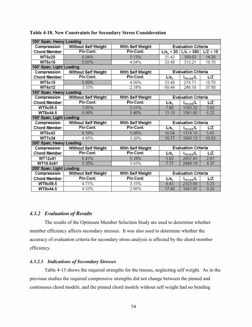
54
Table 4-18. New Constraints for Secondary Stress Consideration
4.3.2 Evaluation of Results
The results of the Optimum Member Selection Study are used to determine whether
member efficiency affects secondary stresses. It was also used to determine whether the
accuracy of evaluation criteria for secondary stress analysis is affected by the chord member
efficiency.
4.3.2.1 Indications of Secondary Stresses
Table 4-13 shows the required strengths for the trusses, neglecting self weight. As in the
previous studies the required compressive strengths did not change between the pinned and
continuous chord models, and the pinned chord models without self weight had no bending

55
moment. The required compressive strengths were unaffected by changing the member size.
The required flexural strength in the chord decreases when the members are downsized,
indicating a decrease in secondary stress. This decrease must be attributed to a decrease in
secondary stress since self weight is not included, so changing the weight of the member does
not affect the required flexural strength.
Table 4-14 shows the required strengths for the trusses, including self weight. The
required compressive strengths remain unaffected between the pinned and continuous chord
models. However, the required compressive strengths decrease when a smaller member is used.
Because this decline does not occur in the models that neglect self weight, it can be attributed to
the use of a lighter member. The pinned chord trusses have a small required flexural strength,
due to self weight, that is slightly decreased when smaller, lighter members are used. The
continuous chord truss model has more of a decrease in required flexural strength, indicating that
secondary stresses are lessened when a smaller member is used. Using a smaller member
increases the deflection of the truss which should indicate an increase in secondary stresses.
However, the chord members experience a decrease in secondary stresses. This decrease in
secondary stresses is caused by the decreased stiffness of the chord member. Under Manderla’s
assumption (Section 3.4.1), the increased deflection is small and causes only a minor increase in
secondary stresses. This minor increase is counteracted by a reduction in secondary stress due to
reduced member stiffness. Because the member is less stiff, less stress is required to achieve the
chord rotation required for truss deflection.
The interaction values resulting from these required strengths are shown in Table 4-15.
The smaller members yield interaction values closer to unity, which indicates a more efficient
design. The interaction value is larger in the more efficient member because the member
capacity is reduced. As in the previous studies, the interaction value increases when the chord
becomes continuous, due to secondary stresses. Also, the interaction values are greater when
self weight is included, due to the extra loading.
4.3.2.2 Prediction of Secondary Stress Severity
The percent increases in interaction value, resulting from chord continuity, are shown in
Table 4-16. Regardless of self weight considerations, the interaction value increased less when
the chord size was reduced. This effect indicates that choosing a more efficient member will
reduce the effects of secondary stresses. However, a more efficient member may not be able to

56
sustain the increase in interaction value, because its value is close to unity. Also, despite chord
size, the inclusion of self weight results in a smaller increase in the interaction value between
pinned and continuous chords, because secondary stress is a smaller portion of the overall
required strength.
The evaluation criteria, in Table 4-17, predicted the magnitude of secondary stresses
similarly to the previous studies. The radius of gyration criterion less than fifty accurately
predicted an increase of greater than five percent for trusses with self weight, with the exception
of one truss (150’ Span, Light Loading, WT7x34). The moment of inertia criterion was a less
reliable predictor, as it incorrectly identified two trusses, and failed to identify one other. The
depth criterion is least accurate, as it did not indicate secondary stress need be considered for any
of the trusses. These results are consistent with the previous studies.
As before, the proposed new evaluation criteria in Table 4-18 do not provide an accurate
prediction for secondary stress consideration. When considering self weight the elastic section
modulus criterion incorrectly identifies four trusses, and fails to identify one other. The moment
of inertia of the truss and the plastic section modulus criteria both incorrectly identify four
trusses for secondary stress consideration. These results indicate that these proposed new criteria
are not related to the increase in interaction values due to induced secondary stresses and cannot
be used as indicators of secondary stress analysis.

57
5 Conclusion
Trusses have many applications and advantages in modern structures. They carry loads
like beams, but are lighter and cheaper. Trusses and their analysis evolved over time to their
present forms. Ideal trusses can be analyzed with graphical or analytical methods. The methods
of joints or sections can be used for most trusses, but some more complex truss structures require
more rigorous analysis.
Secondary stresses in trusses are caused by transverse loading, eccentric connections and
rigid joints. The analysis of trusses under secondary stresses resulted in the development of the
slope-deflection method. When secondary stresses are included in truss analysis, beam-column
design is used to address the addition of bending moment combined with axial compression.
The critical chord member for secondary stress consideration is located at the midpoint of
the compression chord (midspan of the truss). This member is critical because it is in
compression, and has the highest axial force. The three studies performed for this report indicate
the effect of secondary stresses on these critical members. This behavior can be observed in the
changes in required strengths and interaction values from the ideal to the continuous chord
trusses. These affects are observed in the critical compression chord, and the following
conclusions were drawn:
1. When continuous chords are present, secondary stresses induce a bending
moment in the chord members, which increases the required flexural strength.
2. The required flexural strength is smaller when only one of the chord’s
connections is continuous, and the other end has a pinned splice, because only
the rigid connection will produce secondary stresses.
3. Required axial strengths are minimally affected by secondary stresses.
4. Secondary stresses increase required flexural strengths regardless of self weight
consideration.
5. When secondary stresses are present the interaction value of the critical chord
member increases, due to the increase in required flexural strength.

58
6. An increase in member stiffness results in an increase in secondary stresses, in
most cases.
7. Secondary stresses decrease with increasing truss depth, if the span, loads, and
member sizes do not change.
8. Although interaction values increase, they may still meet unity when secondary
stresses are included.
Because of the time-consuming nature of secondary stress analysis, it is advantageous to
have evaluation criteria that will determine whether this analysis is necessary. The following
conclusions can be drawn for secondary stress analysis prediction:
1. An increase of 5% in the interaction value is considered a reasonable guideline
for secondary stress consideration.
2. Trusses with a splice at the critical members do not experience an increase
greater than 5% in interaction value.
3. The increase in interaction value is smaller when self weight is included in the
analysis.
4. There is a larger increase in interaction value due to secondary stresses, as the
member stiffness increases.
5. The increase in interaction value decreases as the depth of the truss increases.
6. The increase in interaction value decreases as the member efficiency increases.
7. The radius of gyration criterion is the most accurate predictor of the necessity
of secondary stress analysis.
8. Moment of inertia of the chord member, moment of inertia of the truss, and
section moduli criteria are less accurate predictors of the necessity of secondary
stress analysis.
9. Depth criterion is not a reliable predictor of severe secondary stresses and
should not be used to dictate secondary stress analysis.

59
6 Recommendation
From the conclusions, recommendations are made regarding the consideration of
secondary stresses in the design of parallel chord Pratt trusses with WT chord members. These
recommendations include:
1. When designing trusses with continuous chords, the radius of gyration criterion
(L/rx < 50) should be used to determine if secondary stress analysis is
necessary.
2. If the criterion indicates that secondary stress analysis is unnecessary, select
members with an interaction value less than 0.95 to account for minor increases
in required flexural strength due to secondary stresses.
3. Include splices at critical chord members, to reduce the effects of secondary
stresses.
4. Select members of lower stiffness to reduce the effects of secondary stresses.
5. Select efficient members to reduce the effects of secondary stresses.
6. When performing secondary stress analysis, include self weight, as this is more
accurate and reduces the effects of secondary stresses.

60
References
Ambrose, James. Design of Building Trusses. New York: John Wiley & Sons, Inc., 1994.
American Association of State Highway and Transportation Officials (AASHTO), (2004).
AASHTO LRFD Bridge Design Specifications, Washington, D.C. American Institute of Steel Construction (AISC), (2005a) Specification for Structural Steel
Buildings, Chicago, IL. American Institute of Steel Construction (AISC), (2005b) Steel Construction Manual,
Chicago, IL. American Iron and Steel Institute (AISI), (2007). North American Standard for Cold-
Formed Steel Framing – Truss Design, AISI S214-07, Washington, D.C. American Society of Civil Engineers (ASCE), (1971). Plastic Design in Steel: A Guide and
Commentary, New York, NY. Brockenbrough, Roger L., and Frederick S. Merritt. Structural Steel Designer’s
Handbook, Third Edition. New York: McGraw-Hill, Inc., 1999. Charlton, T.M. A history of theory of structures in the nineteenth century. Cambridge:
Cambridge University Press, 1982. Chen, W.F. and E.M. Lui (1985). “Columns with end restraint and bending in load and
resistance design factor.” Engineering Journal, 22(3), 105-132. Duan, L, and Chen, W. (1989). “Design interaction equation for steel beam-columns.”
Journal of Structural Engineering, 115(5), 1225-1243. Gaylord, Jr., Edwin H. and Charles N. Gaylord. Structural Engineering Handbook. New
York: McGraw-Hill Book Company, 1968. Grimm, C.R. Secondary Stresses in Bridge Trusses. New York: John Wiley & Sons, 1908. Hibbeler, R.C. Structural Analysis. Upper Saddle River, NJ: Pearson Prentice Hall, 2006. International Code Council, Inc. (ICC), (2006) International Building Code, Washington,
D.C.

61
Korol, R.M., Rutenberg, A. and Bagnariol, D. (1986). “On primary and secondary stresses in triangulated trusses.” Journal of Constructional Steel Research, 6(2), 123-142.
Machaly, El-Sayed Bahaa (1984). “Buckling contribution to the analysis of steel trusses.”
Computers & Structures, 22(3), 445-458. Mori, M., Sato, H., and Hatakeyama, T. (1976). “Fundamental studies on the stress analysis
of triangular trusses.” Memoirs of the Defense Academy, 16(1), 7-49. Nair, R. Shankar (1988). “Secondary stresses in trusses.” Engineering Journal, 25(4), 144. Norris, Charles Head, John Benson Wilbur, and Şenol Utku. Elementary Structural
Analysis, Third Edition. New York: McGraw-Hill Book Company, 1976. RISA-3D Software (RISA 2007), RISA-3D Version 7.0.0, RISA Technologies, Foothill
Ranch, CA. Salmon, Charles G., John E. Johnson, Faris A. Malhas. Steel Structures Design and
Behavior, Fifth Edition. Upper Saddle River, NJ: Pearson Prentice Hall, 2009. Schmits, Brice. Design considerations for parallel chord one-way long-span steel trusses.
Report. Kansas State University, Manhattan, 2008. K-State Research Exchange. Kansas State University, Manhattan, KS. 10 Mar. 2009 <http://krex.k-state.edu>.
Segui, William T. Steel Design, Fourth Edition. Toronto: Thomson, 2007. Sohal, I.S., Duan, L., and Chen, W. (1989). “Design interaction equations for steel
members.” Journal of Structural Engineering, 115(7), 1650-1665. Sputo, Thomas (1993). “History of steel beam-column design.” Journal of Structural
Engineering, 119(2), 547-557. Thomas, H.R. and Brown, D.M. (1975). “Optimum least-cost design of a truss roof system.”
Computers & Structures, 7(1), 13-22. Timoshenko, Stephen P. History of Strength of Materials. New York: McGraw-Hill Book
Company, Inc., 1953. Timoshenko, S. and D.H. Young. Theory of Structures. New York: McGraw-Hill Book
Company, Inc., 1945. Vinnakota, Sriramulu. Steel Structures: Behavior and LRFD. Boston: McGraw-Hill,
2006. Zuk, William. Concepts of Structures. Huntington, New York: Robert E. Krieger
Publishing Co., Inc., 1972.

62
Bibliography
Ambrose, James. Design of Building Trusses. New York: John Wiley & Sons, Inc., 1994.
American Association of State Highway and Transportation Officials (AASHTO), (2004).
AASHTO LRFD Bridge Design Specifications, Washington, D.C. American Institute of Steel Construction (AISC), (2005a) Specification for Structural Steel
Buildings, Chicago, IL. American Institute of Steel Construction (AISC), (2005b) Steel Construction Manual,
Chicago, IL. American Iron and Steel Institute (AISI), (2007). North American Standard for Cold-
Formed Steel Framing – Truss Design, AISI S214-07, Washington, D.C. American Society of Civil Engineers (ASCE), (1971). Plastic Design in Steel: A Guide and
Commentary, New York, NY. Brockenbrough, Roger L., and Frederick S. Merritt. Structural Steel Designer’s
Handbook, Third Edition. New York: McGraw-Hill, Inc., 1999. Charlton, T.M. A history of theory of structures in the nineteenth century. Cambridge:
Cambridge University Press, 1982. Chen, W.F. and E.M. Lui (1985). “Columns with end restraint and bending in load and
resistance design factor.” Engineering Journal, 22(3), 105-132. Cheong-Siat-Moy, Francois and Tom Downs (1980). “New Interaction Equation for Steel
Beam-Columns.” ASCE Journal of the Structural Division, 106(5), 1047-1061. Duan, L, and Chen, W. (1989). “Design interaction equation for steel beam-columns.”
Journal of Structural Engineering, 115(5), 1225-1243. Eshbach, Ovid W. Handbook of Engineering Fundamentals. New York: John Wiley &
Sons, Inc., 1936. Gaylord, Jr., Edwin H. and Charles N. Gaylord. Structural Engineering Handbook. New
York: McGraw-Hill Book Company, 1968. Grimm, C.R. Secondary Stresses in Bridge Trusses. New York: John Wiley & Sons, 1908.

63
Hibbeler, R.C. Structural Analysis. Upper Saddle River, NJ: Pearson Prentice Hall, 2006. International Code Council, Inc. (ICC), (2006) International Building Code, Washington,
D.C. Korol, R.M., Rutenberg, A. and Bagnariol, D. (1986). “On primary and secondary stresses in
triangulated trusses.” Journal of Constructional Steel Research, 6(2), 123-142. Machaly, El-Sayed Bahaa (1984). “Buckling contribution to the analysis of steel trusses.”
Computers & Structures, 22(3), 445-458. Mori, M., Sato, H., and Hatakeyama, T. (1976). “Fundamental studies on the stress analysis
of triangular trusses.” Memoirs of the Defense Academy, 16(1), 7-49. Nair, R. Shankar (1988). “Secondary stresses in trusses.” Engineering Journal, 25(4), 144. Norris, Charles Head, John Benson Wilbur, and Şenol Utku. Elementary Structural
Analysis, Third Edition. New York: McGraw-Hill Book Company, 1976. RISA-3D Software (RISA 2007), RISA-3D Version 7.0.0, RISA Technologies, Foothill
Ranch, CA. Salmon, Charles G., John E. Johnson, Faris A. Malhas. Steel Structures Design and
Behavior, Fifth Edition. Upper Saddle River, NJ: Pearson Prentice Hall, 2009. Schmits, Brice. Design considerations for parallel chord one-way long-span steel trusses.
Report. Kansas State University, Manhattan, 2008. K-State Research Exchange. Kansas State University, Manhattan, KS. 10 Mar. 2009 <http://krex.k-state.edu>.
Segui, William T. Steel Design, Fourth Edition. Toronto: Thomson, 2007. Sohal, I.S., Duan, L., and Chen, W. (1989). “Design interaction equations for steel
members.” Journal of Structural Engineering, 115(7), 1650-1665. Sputo, Thomas (1993). “History of steel beam-column design.” Journal of Structural
Engineering, 119(2), 547-557. Thomas, H.R. and Brown, D.M. (1975). “Optimum least-cost design of a truss roof system.”
Computers & Structures, 7(1), 13-22. Timoshenko, Stephen P. History of Strength of Materials. New York: McGraw-Hill Book
Company, Inc., 1953. Timoshenko, Stephen P. (1945). “Theory of bending, torsion and buckling of thin-walled
members of open cross section.” Journal of the Franklin Institute, 239, 201-219.

64
Timoshenko, S. and D.H. Young. Theory of Structures. New York: McGraw-Hill Book Company, Inc., 1945.
Vinnakota, Sriramulu. Steel Structures: Behavior and LRFD. Boston: McGraw-Hill,
2006. Zuk, William. Concepts of Structures. Huntington, New York: Robert E. Krieger
Publishing Co., Inc., 1972.

65
Appendix A – Method of Joints for Truss Analysis
Parameters ����
� 20’ OC Spacing � 15 psf Dead Load � 20 psf Live Load � Webs: 36 ksi Double Angles � Chords: 50 ksi W-Tees
Calculate P ����
psfpsfpsf 50)20(6.1)15(2.1 =+
klbsftftpsfP 10000,10)20)(10)(50( ===
kkP
52
10
2==
Figure A-1. Truss with Loads
Calculate Reactions ����
)102030405060708090()100(2
)100(0 ++++++++++−==∑ PP
AM yB
kAy 50=

66
( )922
0 PP
BAF yyy +
++==∑
kBy 50=
Determine Member Forces by Method of Joints ����
Each joint is considered separately, starting with Joint 2. Once joint 2 is solved, the
method of joints moves systematically through the truss, to each joint. Due to symmetry, only
half of the truss needs to be analyzed.
Figure A-2. Joint 2
21500 −+==∑ FFy nCompressiokkF 505021 =−=−
∑ −== 420 FFx kF 042 =−
Figure A-3. Joint 1
)45sin(5050 41 °−+−== −∑ FFy TensionkkF 64.6364.6341 ==−
∑ −− +°== 3141 )45cos(0 FFFx nCompressiokkF 454531 =−=−
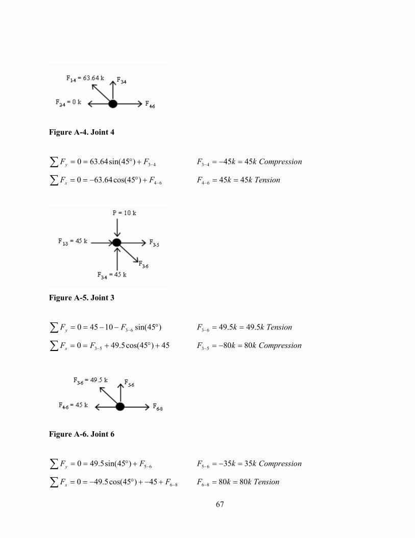
67
Figure A-4. Joint 4
43)45sin(64.630 −+°==∑ FFy nCompressiokkF 454543 =−=−
∑ −+°−== 64)45cos(64.630 FFx TensionkkF 454564 ==−
Figure A-5. Joint 3
)45sin(10450 63 °−−== −∑ FFy TensionkkF 5.495.4963 ==−
∑ +°+== − 45)45cos(5.490 53FFx nCompressiokkF 808053 =−=−
Figure A-6. Joint 6
65)45sin(5.490 −+°==∑ FFy nCompressiokkF 353565 =−=−
∑ −+−+°−== 8645)45cos(5.490 FFx TensionkkF 808086 ==−

68
Figure A-7. Joint 5
)45sin(10350 85 °−−== −∑ FFy TensionkkF 36.3536.3585 ==−
∑ +°+== − 80)45cos(36.350 75FFx nCompressiokkF 10510575 =−=−
Figure A-8. Joint 8
87)45sin(36.350 −+°==∑ FFy nCompressiokkF 252587 =−=−
∑ −+−°−== 10880)45cos(36.350 FFx TensionkkF 105105108 ==−
Figure A-9. Joint 7

69
)45sin(10250 107 °−−== −∑ FFy TensionkkF 21.2121.21107 ==−
∑ +°+== − 105)45cos(21.210 97FFx nCompressiokkF 12012097 =−=−
Figure A-10. Joint 10
109)45sin(21.210 −+°==∑ FFy nCompressiokkF 1515109 =−=−
∑ −+−°−== 1210105)45cos(21.210 FFx TensionkkF 1201201210 ==−
Figure A-11. Joint 9
)45sin(10150 129 °−−== −∑ FFy TensionkkF 07.707.7129 ==−
∑ +°+== − 120)45cos(07.70 119FFx nCompressiokkF 125125119 =−=−
By observation F11-12 = 0 k.
Size Web Members ����
Web members were grouped for practicality based on force, to reduce the number of different
member sizes.

70
Size compression members based on AISC Table 4-8 (AISC 2005b) �
Member Size
1-2, 3-4 2 L 3 x 3 x 3/8
5-6, 7-8 2 L 3 x 3 x ¼
9-10, 11-12 2 L 2 ½ x 2 ½ x ¼
Size tension members based on AISC Table 5-8 (AISC 2005b) �
Member Size
1-4, 3-6 2 L 2 ½ x 2 ½ x ¼
5-8, 7-10 2 L 2 x 2 x 3/16
9-10, 11-12 2 L 2 x 2 x 1/8
Size Chord Members ����
Since the chords are continuous, the maximum force will be used to select one chord size. To
simplify construction, the tension and compression chord will be the same size. The
compression chord force will control the sizing.
Size chord members based on AISC Table 4-7 (AISC 2005b) �
Member Size
Chords WT 5x19.5
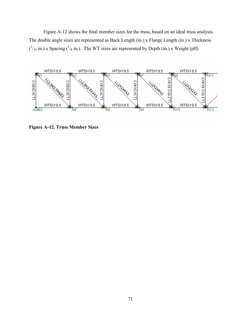
71
Figure A-12 shows the final member sizes for the truss, based on an ideal truss analysis.
The double angle sizes are represented as Back Length (in.) x Flange Length (in.) x Thickness
(1/16 in.) x Spacing (1/8 in.). The WT sizes are represented by Depth (in.) x Weight (plf)
Figure A-12. Truss Member Sizes

72
Appendix B – Truss Moment of Inertia Calculations
The truss moments of inertia were calculated manually. They were calculated about the
center of gravity of the truss cross section, and include only the top and bottom chords. The
following is an example of the calculation:
Truss Properties ����
Top Chord: WT4x29
A = 8.54 in2 (AISC 2005b Table 1-8)
I = 9.12 in4 (AISC 2005b Table 1-8)
Bottom Chord: WT5x19.5
A = 5.73 in2 (AISC 2005b Table 1-8)
I = 8.84 in4 (AISC 2005b Table 1-8)
Truss Depth: d = 120 in
Calculate Center of Gravity of Chords �
81.7173.554.8
)120)(54.8())((=
+=
+=
bottop
top
AA
dACG in from bottom
19.4881.71120 =−=−= botCGdCG in from top
Calculate Moment of Inertia of Truss ����
2222 )81.71)(73.5(84.8)19.48)(54.8(12.9))(())(( +++=+++= botbotbottoptoptopT CGAICGAII
4398,49 inIT =

73
This method is repeated for each truss studied, and the results are shown in Table B-1:
Table B-1. Truss Moments of Inertia

74
Appendix C – Figure Use Permission
AMERICAN SOCIETY OF CIVIL ENGINEERS LICENSE TERMS AND CONDITIONS
Mar 04, 2009
This is a License Agreement between Megan C Smith ("You") and American Society of Civil Engineers ("American Society of Civil Engineers") provided by Copyright Clearance Center ("CCC"). The license consists of your order details, the terms and conditions provided by American Society of Civil Engineers, and the payment terms and conditions.
All payments must be made in full to CCC. For payment instructions, please see
information listed at the bottom of this form.
License Number 2142150778459
License date Mar 04, 2009
Licensed content title Design Interaction Equations for Steel Members
Licensed content author Iqbal S. Sohal; Lian Duan; Wai-Fah Chen
Licensed content publication Journal of Structural Engineering
Licensed content publisher American Society of Civil Engineers
Type of Use Doctoral Thesis
Portion used Figure
Number of figures 1
Institution Kansas State University
Title of your work http://krex.k-state.edu/dspace/
Publisher of your work K-State Research Exchange
Publication date of your work 05/15/2009
Website http://krex.k-state.edu/dspace/
Usage both

75
Billing Type Invoice
Company Megan C Smith
Billing Address 925 Denison Ave #11
Manhattan, KS 66502
United States
Customer reference info
Total $0.00
Terms and Conditions
A Terms and Conditions agreement is a document that describes the terms and conditions of a license to the licensee. ASCE Terms and Conditions are available during the order process, although you may review the Terms and Conditions below, before placing an order. The publisher for this copyrighted material is The American Society of Civil Engineers (ASCE). By clicking "accept", you agree that the following terms and conditions apply to this transaction, along with the billing and payment terms and conditions established by Copyright Clearance Center, Inc. (CCC) at the time that you opened your Rightslink® account. The terms and conditions information is available when you log in to Rightslink.
One Time Permission Each license is unique, covering only the terms and conditions specified in it. Even if you have obtained a license for certain ASCE-copyrighted content, you will need to obtain another license if you plan to reuse that content outside the terms of the existing license. For example: If you already have a license to reuse a figure in a journal, you still need a new license to use the same figure in a magazine.
Embargo Permission will be denied if the content is requested within 3 months of the publication date.
No-Fee License A $0 license is granted to authors who wish to reuse their own content and to authors who wish to reuse ASCE-copyrighted content in their works prepared for another ASCE publication.
Credit Lines A full credit line must be added to the material being reprinted.
• For reuse in non-ASCE publications, add the words "With permission from ASCE" to your source citation.

76
• For reuse in ASCE publications, add a comma and "ASCE" after the author-date citation. For example: (Jones and Taylor 2003, ASCE)
• For online posting, add the following additional notice: "This material may be downloaded for personal use only. Any other use requires prior permission of the American Society of Civil Engineers. This material may be found at [URL/link of abstract in the Civil Engineering Database]." (Online use is a limited use that is essentially equivalent to or substitutes for the print version, and embedded material (or a specific link to it) remains in situ; it does not include use as part of a database or other uses that might conflict with or prejudice the usage of the material by ASCE.)
Online Coursepack
The site must be password protected and posted for the semester only.
ASCE Magazines
Permissions granted only for text from Civil Engineering magazine and ASCE News. Permission
to use photographs, graphics, figures, or tables must be requested from the copyright owner as
noted in the credit line.
Materials Not Copyrighted by ASCE
The requesting party is responsible for ensuring that the material is original to ASCE and that it
does not contain the copyright of another entity or reference that it was reprinted by ASCE with
permission from another source.
General
The foregoing License shall not take effect unless and until ASCE or CCC receives the payment
in accordance with the CCC Billing and Payment Terms and Conditions (including all payment
provisions), which are incorporated herein by reference. Failure to fully comply with the terms of
this License or the CCC Billing and Payment Terms and Conditions shall automatically render
this License null and void.
ASCE or CCC may, at any time, deny the permissions described in this License at their sole
discretion, for any reason or no reason, with a full refund payable to you. Notice of such denial
will be made using the contact information provided by you. Failure to receive such notice will

77
not alter or invalidate the denial. In no event will ASCE or CCC be responsible or liable for any
costs, expenses or damage incurred by you as a result of a denial of your permission request,
other than a refund of the amount(s) paid by you to CCC for denied permissions.
Gratis licenses (referencing $0 in the Total field) are free. Please retain this printable
license for your reference. No payment is required.
If you would like to pay for this license now, please remit this license along with your payment made payable to "COPYRIGHT CLEARANCE CENTER" otherwise you will be invoiced within 30 days of the license date. Payment should be in the form of a check or money order referencing your account number and this license number 2142150778459. If you would prefer to pay for this license by credit card, please go to http://www.copyright.com/creditcard to download our credit card payment authorization form. Make Payment To: Copyright Clearance Center Dept 001 P.O. Box 843006 Boston, MA 02284-3006 If you find copyrighted material related to this license will not be used and wish to cancel, please contact us referencing this license number 2142150778459 and noting the reason for cancellation. Questions? [email protected] or +1-877-622-5543 (toll free in the US) or +1-978-646-2777.