amphenol gt series reversed bayonet coupling connectors · amphenol gt connectors® wall mount...
TRANSCRIPT

Amphenol GT SeriesReversed Bayonet Coupling Connectors12-024-4
Amphenol
®

Table of Contents Page No.Amphenol® GT Series Reversed Bayonet Coupling ConnectorsGeneral Description . . . . . . . . . . . . . . . . . . . . . . . . . . . . . . . . . . . . 1MS/Standard insert availability charts . . . . . . . . . . . . . . . . . . . . . . . . . . . . . 2, 3Special insert availability chart . . . . . . . . . . . . . . . . . . . . . . . . . . . . . . . . 4MS/Standard insert alternate positioning . . . . . . . . . . . . . . . . . . . . . . . . . . . . . 5MS/Standard contact arrangements . . . . . . . . . . . . . . . . . . . . . . . . . . . . . .6-17Special contact arrangements. . . . . . . . . . . . . . . . . . . . . . . . . . . . . . . 18-26Thermocouple contact availability . . . . . . . . . . . . . . . . . . . . . . . . . . . . . . 27Thermocouple contact arrangements . . . . . . . . . . . . . . . . . . . . . . . . . . . . 28-31GT Connector Classes . . . . . . . . . . . . . . . . . . . . . . . . . . . . . . . . . . 32
GT00A wall mount receptacle for front panel mounting . . . . . . . . . . . . . . . . . . . . . . 33GT00AF/00F wall mount receptacle for front panel mounting . . . . . . . . . . . . . . . . . . . . 34GT00CF/00CFZ wall mount receptacle for front panel mounting . . . . . . . . . . . . . . . . . . . 35GT00G wall mount receptacle for front panel mounting . . . . . . . . . . . . . . . . . . . . . . 36GT00LCF/00LCFZ wall mount receptacle for front panel mounting . . . . . . . . . . . . . . . . . . 37GT00R wall mount receptacle for front panel mounting . . . . . . . . . . . . . . . . . . . . . . 38GT00RV wall mount receptacle for front panel mounting . . . . . . . . . . . . . . . . . . . . . 39GT01A inline receptacle . . . . . . . . . . . . . . . . . . . . . . . . . . . . . . . 40GT01AF/01F inline receptacle . . . . . . . . . . . . . . . . . . . . . . . . . . . . . . 41GT01G inline receptacle . . . . . . . . . . . . . . . . . . . . . . . . . . . . . . . 42GT01LCF/01LCFZ inline receptacle . . . . . . . . . . . . . . . . . . . . . . . . . . . . 43GT01R inline receptacle . . . . . . . . . . . . . . . . . . . . . . . . . . . . . . . 44GT01RV inline receptacle . . . . . . . . . . . . . . . . . . . . . . . . . . . . . . . 45GT02R/02RFS box mount receptacle for front panel mounting. . . . . . . . . . . . . . . . . . . . 46GT020R/020RFSM box mount receptacle for front panel mounting . . . . . . . . . . . . . . . . . . 47GT030 square flange receptacle for rear panel mounting . . . . . . . . . . . . . . . . . . . . . 48GT030A square flange receptacle for rear panel mounting . . . . . . . . . . . . . . . . . . . . . 49GT030AF/030F square flange receptacle for rear panel mounting . . . . . . . . . . . . . . . . . . 50GT030G square flange receptacle for rear panel mounting . . . . . . . . . . . . . . . . . . . . . 51GT030R square flange receptacle for rear panel mounting . . . . . . . . . . . . . . . . . . . . . 52GT030RV square flange receptacle for rear panel mounting . . . . . . . . . . . . . . . . . . . . 53GT06A straight plug . . . . . . . . . . . . . . . . . . . . . . . . . . . . . . . . . 54GT06AF/06F straight plug . . . . . . . . . . . . . . . . . . . . . . . . . . . . . . . 55GT06CF straight plug . . . . . . . . . . . . . . . . . . . . . . . . . . . . . . . . 56GT06CFGG straight plug . . . . . . . . . . . . . . . . . . . . . . . . . . . . . . . 57GT06G straight plug . . . . . . . . . . . . . . . . . . . . . . . . . . . . . . . . . 58GT06LC straight plug . . . . . . . . . . . . . . . . . . . . . . . . . . . . . . . . 59GT06LCF/06LCFZ straight plug . . . . . . . . . . . . . . . . . . . . . . . . . . . . . 60GT06PP/064PP panel plug . . . . . . . . . . . . . . . . . . . . . . . . . . . . . . 61GT06R straight plug . . . . . . . . . . . . . . . . . . . . . . . . . . . . . . . . . 62GT06RV straight plug . . . . . . . . . . . . . . . . . . . . . . . . . . . . . . . . 63GT065SL straight plug . . . . . . . . . . . . . . . . . . . . . . . . . . . . . . . . 64GT07R jam nut receptacle . . . . . . . . . . . . . . . . . . . . . . . . . . . . . . . 65GT070 jam nut receptacle . . . . . . . . . . . . . . . . . . . . . . . . . . . . . . . 66GT08A 90° angle plug . . . . . . . . . . . . . . . . . . . . . . . . . . . . . . . . 67GT08AF/08F 90° angle plug . . . . . . . . . . . . . . . . . . . . . . . . . . . . . . 68GT08CFGG 90° angle plug . . . . . . . . . . . . . . . . . . . . . . . . . . . . . . 69GT08R 90° angle plug . . . . . . . . . . . . . . . . . . . . . . . . . . . . . . . . 70GT05 dummy receptacle . . . . . . . . . . . . . . . . . . . . . . . . . . . . . . . 71GTTB thru-bulkhead receptacles . . . . . . . . . . . . . . . . . . . . . . . . . . . . . 72
Sealing gaskets . . . . . . . . . . . . . . . . . . . . . . . . . . . . . . . . . . . . 73Receptacle protection caps . . . . . . . . . . . . . . . . . . . . . . . . . . . . . . . . 74Plug protection caps. . . . . . . . . . . . . . . . . . . . . . . . . . . . . . . . . . . 75M85049/41 (MS3057-A) cable clamp . . . . . . . . . . . . . . . . . . . . . . . . . . . . . 76MS3420 bushing . . . . . . . . . . . . . . . . . . . . . . . . . . . . . . . . . . . . 77M85049/2 (MS3057-C) cable clamp . . . . . . . . . . . . . . . . . . . . . . . . . . . . . . 78Rear mounting data - receptacles, sealing plugs, sealing ranges, backshell torque forces . . . . . . . . . . . . . 79Solder and crimp contact information . . . . . . . . . . . . . . . . . . . . . . . . . . . . 80, 81MS/Standard application tools. . . . . . . . . . . . . . . . . . . . . . . . . . . . . . . . 82How to order, connector intermateability . . . . . . . . . . . . . . . . . . . . . . . . . . . . 83Special Application GT Connectors:
GT-PC Connectors for high voltage power applicationsGT Connectors for the HMI lighting industry . . . . . . . . . . . . . . . . . . . . . . . . . 84
Sales office listing
Amphenol Aerospace is a Certified ISO 9001 Manufacturer
1
®Amphenol GT Connectors
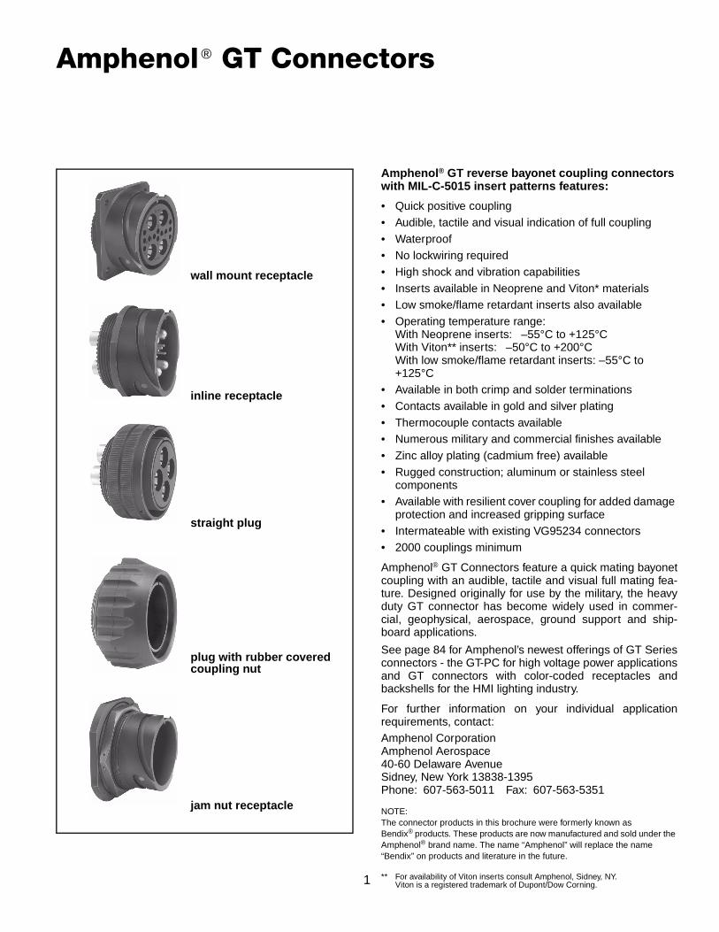
wall mount receptacle
inline receptacle
straight plug
plug with rubber coveredcoupling nut
jam nut receptacle
Amphenol® GT reverse bayonet coupling connectors with MIL-C-5015 insert patterns features:
• Quick positive coupling• Audible, tactile and visual indication of full coupling• Waterproof• No lockwiring required• High shock and vibration capabilities• Inserts available in Neoprene and Viton* materials• Low smoke/flame retardant inserts also available• Operating temperature range:
With Neoprene inserts: –55°C to +125°CWith Viton** inserts: –50°C to +200°CWith low smoke/flame retardant inserts: –55°C to +125°C
• Available in both crimp and solder terminations• Contacts available in gold and silver plating• Thermocouple contacts available• Numerous military and commercial finishes available• Zinc alloy plating (cadmium free) available• Rugged construction; aluminum or stainless steel
components• Available with resilient cover coupling for added damage
protection and increased gripping surface• Intermateable with existing VG95234 connectors• 2000 couplings minimum
Amphenol® GT Connectors feature a quick mating bayonetcoupling with an audible, tactile and visual full mating fea-ture. Designed originally for use by the military, the heavyduty GT connector has become widely used in commer-cial, geophysical, aerospace, ground support and ship-board applications.
See page 84 for Amphenol’s newest offerings of GT Seriesconnectors - the GT-PC for high voltage power applicationsand GT connectors with color-coded receptacles andbackshells for the HMI lighting industry.
For further information on your individual applicationrequirements, contact:Amphenol CorporationAmphenol Aerospace40-60 Delaware AvenueSidney, New York 13838-1395Phone: 607-563-5011 Fax: 607-563-5351
NOTE:The connector products in this brochure were formerly known asBendix® products. These products are now manufactured and sold under the Amphenol® brand name. The name “Amphenol” will replace the name“Bendix” on products and literature in the future.
** For availability of Viton inserts consult Amphenol, Sidney, NY.Viton is a registered trademark of Dupont/Dow Corning.
2
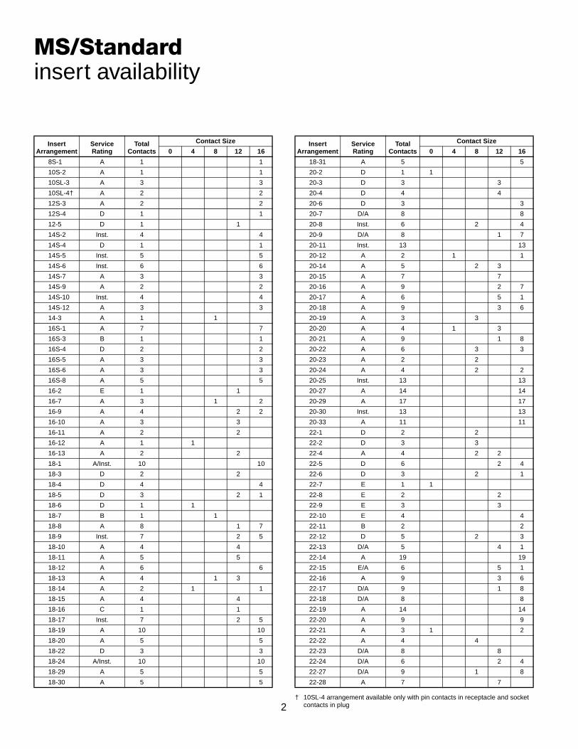
MS/Standardinsert availability
InsertArrangement
ServiceRating
TotalContacts
Contact Size
0 4 8 12 16
8S-1 A 1 1
10S-2 A 1 1
10SL-3 A 3 3
10SL-4† A 2 2
12S-3 A 2 2
12S-4 D 1 1
12-5 D 1 1
14S-2 Inst. 4 4
14S-4 D 1 1
14S-5 Inst. 5 5
14S-6 Inst. 6 6
14S-7 A 3 3
14S-9 A 2 2
14S-10 Inst. 4 4
14S-12 A 3 3
14-3 A 1 1
16S-1 A 7 7
16S-3 B 1 1
16S-4 D 2 2
16S-5 A 3 3
16S-6 A 3 3
16S-8 A 5 5
16-2 E 1 1
16-7 A 3 1 2
16-9 A 4 2 2
16-10 A 3 3
16-11 A 2 2
16-12 A 1 1
16-13 A 2 2
18-1 A/Inst. 10 10
18-3 D 2 2
18-4 D 4 4
18-5 D 3 2 1
18-6 D 1 1
18-7 B 1 1
18-8 A 8 1 7
18-9 Inst. 7 2 5
18-10 A 4 4
18-11 A 5 5
18-12 A 6 6
18-13 A 4 1 3
18-14 A 2 1 1
18-15 A 4 4
18-16 C 1 1
18-17 Inst. 7 2 5
18-19 A 10 10
18-20 A 5 5
18-22 D 3 3
18-24 A/Inst. 10 10
18-29 A 5 5
18-30 A 5 5
† 10SL-4 arrangement available only with pin contacts in receptacle and socket contacts in plug
18-31 A 5 5
20-2 D 1 1
20-3 D 3 3
20-4 D 4 4
20-6 D 3 3
20-7 D/A 8 8
20-8 Inst. 6 2 4
20-9 D/A 8 1 7
20-11 Inst. 13 13
20-12 A 2 1 1
20-14 A 5 2 3
20-15 A 7 7
20-16 A 9 2 7
20-17 A 6 5 1
20-18 A 9 3 6
20-19 A 3 3
20-20 A 4 1 3
20-21 A 9 1 8
20-22 A 6 3 3
20-23 A 2 2
20-24 A 4 2 2
20-25 Inst. 13 13
20-27 A 14 14
20-29 A 17 17
20-30 Inst. 13 13
20-33 A 11 11
22-1 D 2 2
22-2 D 3 3
22-4 A 4 2 2
22-5 D 6 2 4
22-6 D 3 2 1
22-7 E 1 1
22-8 E 2 2
22-9 E 3 3
22-10 E 4 4
22-11 B 2 2
22-12 D 5 2 3
22-13 D/A 5 4 1
22-14 A 19 19
22-15 E/A 6 5 1
22-16 A 9 3 6
22-17 D/A 9 1 8
22-18 D/A 8 8
22-19 A 14 14
22-20 A 9 9
22-21 A 3 1 2
22-22 A 4 4
22-23 D/A 8 8
22-24 D/A 6 2 4
22-27 D/A 9 1 8
22-28 A 7 7
InsertArrangement
ServiceRating
TotalContacts
Contact Size
0 4 8 12 16

3
MS/Standardinsert availability, cont.
InsertArrangement
ServiceRating
TotalContacts
Contact Size
0 4 8 12 16
22-33 D/A 7 7
22-34 D 5 3 2
24-2 D 7 7
24-3 D 7 2 5
24-5 A 16 16
24-6 D/A 8 8
24-7 A 16 2 14
24-9 A 2 2
24-10 A 7 7
24-11 A 9 3 6
24-12 A 5 2 3
24-16 D/A 7 1 3 3
24-17 D 5 2 3
24-20 D 11 2 9
24-21 D 10 1 9
24-22 D 4 4
24-27 E 7 7
24-28 Inst. 24 24
28-1 D/A 9 3 6
28-2 D 14 2 12
28-3 E 3 3
28-4 E/D 9 2 7
28-5 D 5 2 1 2
28-6 D 3 3
28-7 D 2 2
28-8 E/D/A 12 2 10
28-9 D 12 6 6
28-10 D/A 7 2 2 3
28-11 A 22 4 18
28-12 A 26 26
28-13 A 26 26
28-15 A 35 35
28-16 A 20 20
28-17 B/D/A 15 15
28-18 C/D/A/Inst. 12 12
28-19 B/D/A 10 4 6
28-20 A 14 10 4
28-21 A 37 37
28-22 D 6 3 3
32-1 E/D 5 2 3
32-2 E 5 3 2
32-3 D 9 1 2 2 4
32-4 A/D 14 2 12
32-5 D 2 2
32-6 A 23 2 3 2 16
32-7 Inst./A 35 7 28
32-8 A 30 6 24
32-9 D 14 2 12
32-10 E/B/D/A 7 2 2 3
32-12 A/D 15 5 10
32-13 D 23 5 18
32-15 D 8 2 6
32-16 A 23 2 3 2 16
32-17 D 4 4
32-22 A 54 54
32-31 A 31 31
36-1 D 22 4 18
36-3 D 6 3 3
36-4 D/A 3 3
36-5 A 4 4
36-6 A 6 2 4
36-7 A 47 7 40
36-8 A 47 1 46
36-9 A 31 1 2 14 14
36-10 A 48 48
36-11 A 48 48
36-12 A 48 48
36-13 E/A 17 2 15
36-14 D 16 5 5 6
36-15 D/A 35 35
36-16 A 47 7 40
36-17 A 47 7 40
36-18 A 31 1 2 14 14
36-20 A 34 2 2 30
36-52 A 52 52
40-1 D 30 6 24
40-9 A 47 1 22 24
40-56 A 85 85
InsertArrangement
ServiceRating
TotalContacts
Contact Size
0 4 8 12 16

4
InsertArrange
mentServiceRating
TotalCon-tacts
Contact Size
0 4 8 12 16
Coax**
0 4 8 12
14-A7 A 7 7
16-59 A 4 4
20-51 A 3 3
20-57 A 7 7*
20-58 A 10 5 5
20-59 A 3 3*
20-66 A 6 5* 1
20-79 A/D 8 1 7
22-63 A 12 4 8
22-65 A/D 8 8*
22-70 A 13 8 5
22-80 A 3 3*
24-51 A 5 5
24-52 Hi Volt. 1 1
24-53 A 5 5
24-58 A 13 3 3 7
24-59 A 14 7 7
24-60 A 7 7*
24-65 A 15 11 4
24-66 D 7 7
24-67 Inst. 19 19
24-71 A 7 7*
24-75 A 7 7*
24-79 A 5 5
24-80 Inst. 23 23
24-84 A 19 1 18
24-96 Inst. 28 28
24-AJ A 25 25
28-51 A 12 12
28-59 A 17 7 10
28-66 A 16 2 14
28-72 Coax 3 3
28-74 A 16 7* 9
28-75 A 16 7* 9
28-79 A 16 7 9
28-82 D 6 2 4
28-84 A 9 9
28-AY A 9 4 5
32-25 A 25 25
32-52 D 8 2 6
32-53 Inst./E 42 5 37
32-56 A 30 6* 24
32-57 Coax 8 6 2
32-58 Coax 4 4
32-60 A 23 15 8
32-62 Coax 23 2 1 2 16 2
32-64 Inst. 54 54
32-68 A 16 12 4
Specialinsert availability
** Coaxial cable data can be found on insert arrangement drawings, pages 18-26. For further information on coaxial contacts and cable see catalog 12-130.
32-73 A 46 46
32-75 Coax 9 2 7
32-76 A 19 19
32-79 D 5 4 1
32-82 A 16 4 12
32-AF A 55 55
36-51 D 4 2 2
36-54 A 39 8 31
36-55 A 39 8* 31
36-59 A 53 3* 50
36-60 A 47 7* 40
36-64 Coax 4 4
36-65 Coax 4 4
36-71 A 53 3 50
36-73 Coax 7 7
36-74 A 44 43 1
36-75 A 48 48*
36-76 A 47 47
36-77 D 7 7
36-78 A 14 12 2
36-79 A 20 20
36-80 A 20 20*
36-83 Coax 7 7
36-85 A/D 35 35*
36-AF A 48 48
40-5 A 5 5
40-10 A 29 4 9 16
40-35 D 35 35
40-53 A 60 60
40-57 E 4 4
40-61 A 59 1 3 55
40-62 A 60 60
40-63 A 61 61*
40-64 Coax 36 3 20 13
40-66 Coax 4 4
40-67 A 11 1 10
40-68 A 21 21
40-70 A 61 61
40-72 A 11 1 10
40-73 A 61 61
40-74 A 6 1 4 1
40-75 E 5 4 1
40-80 A 11 10 1
40-81 A 62 62*
40-82 A 62 62
40-85 A 60 60*
40-86 E 4 4
40-87 D 7 7
40-AG A 38 38
InsertArrange
mentServiceRating
TotalCon-tacts
Contact Size
0 4 8 12 16
Coax**
0 4 8 12
* Crimp contacts accommodate wire the same size as the contact as well as wire of the next smaller, even size. Arrangements identified with an asterisk (*) are exceptions. See insert arrangement drawings on pages 18-26 for application wire size.
5
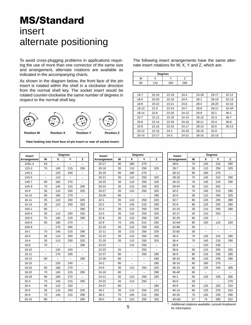
To avoid cross-plugging problems in applications requir-ing the use of more than one connector of the same sizeand arrangement, alternate rotations are available asindicated in the accompanying charts.
As shown in the diagram below, the front face of the pininsert is rotated within the shell in a clockwise directionfrom the normal shell key. The socket insert would berotated counter-clockwise the same number of degrees inrespect to the normal shell key.
Position W Position X Position Y Position Z
View looking into front face of pin insert or rear of socket insert.
The following insert arrangements have the same alter-nate insert rotations for W, X, Y and Z, which are:
Degrees
W X Y Z
80 110 250 280
16-7 20-16 22-18 24-4 24-28 28-17 32-12
18-5 20-20 22-19 24-5 28-1 28-19 32-13
18-9 20-22 22-21 24-6 28-4 28-20 32-22
18-13 22-3 22-24 24-7 28-8 28-21 32-AF
18-14 22-6 22-25 24-12 28-9 32-1 36-1
20-7 22-12 22-29 24-14 28-10 32-3 36-7
20-8 22-14 22-33 24-16 28-11 32-4 36-8
20-9 22-15 22-34 24-17 28-14 32-6 36-13
20-12 22-16 24-1 24-20 28-15 32-9
20-14 22-17 24-3 24-21 28-16 32-10
MS/Standardinsertalternate positioning
InsertArrangement
Degrees
W X Y Z
10SL-4 63 – – –
12S-3 70 145 215 290
14S-2 – 120 240 –
14S-5 – 110 – –
14S-7 90 180 270 –
14S-9 70 145 215 290
16-9 35 110 250 325
16-10 90 180 270 –
16-11 35 110 250 325
16-13 35 110 250 325
16S-1 80 – – 280
16S-4 35 110 250 325
16S-5 70 145 215 290
16S-6 90 180 270 –
16S-8 – 170 265 –
18-1 70 145 215 290
18-3 35 110 250 325
18-4 35 110 250 325
18-8 70 – – 290
18-10 – 120 240 –
18-11 – 170 265 –
18-12 80 – – 280
18-15 – 120 240 –
18-20 90 180 270 –
18-22 70 145 215 290
18-29 90 180 270 –
20-3 70 145 215 290
20-4 45 110 250 –
20-5 35 110 250 325
20-6 70 145 215 290
20-15 80 – – 280
20-17 90 180 270 –
20-18 35 110 250 325
20-19 90 180 270 –
20-21 35 110 250 325
20-23 35 110 250 325
20-24 35 110 250 325
20-27 35 110 250 325
20-29 80 – – 280
22-1 35 110 250 325
22-2 70 145 215 290
22-4 35 110 250 325
22-5 35 110 250 325
22-8 35 110 250 325
22-9 70 145 215 290
22-10 35 110 250 325
22-11 35 110 250 325
22-13 35 110 250 325
22-20 35 110 250 325
22-22 – 110 250 –
22-23 35 – 250 –
22-27 80 – 250 280
22-28 80 – – 280
24-2 80 – – 280
24-9 35 110 250 325
24-10 80 – – 280
24-11 35 110 250 325
24-22 45 110 250 –
24-27 80 – – 280
28-2 35 110 250 325
28-3 70 145 215 290
28-5 35 110 250 325
InsertArrangement
Degrees
W X Y Z
* Additional rotations available; consult Amphenol for information.
28-6 70 145 215 290
28-7 35 110 250 325
28-12 90 180 270 –
28-18 70 145 215 290
28-22 70 145 215 290
28-AY 45 110 250 –
32-2 70 145 215 290
32-5 35 110 250 325
32-7 80 125 235 280
32-8 80 125 235 280
32-15 35 110 250 280
32-17 45 110 250 –
32-25 60 120 – –
32-64* 80 100 110 250
32-68 30 – – –
32-82 30 – – –
36-3 70 145 215 290
36-4 70 145 215 290
36-5 – 120 240 –
36-6 35 110 250 325
36-9 80 125 235 280
36-10 80 125 235 280
36-14 90 180 270 –
36-15 60 125 245 305
36-AF 65 – – –
40-1 65 130 235 300
40-5 33 – – 270
40-9 65 125 225 310
40-10 65 125 225 310
40-35 70 130 230 290
40-AG 37 74 285 322
InsertArrangement
Degrees
W X Y Z
6
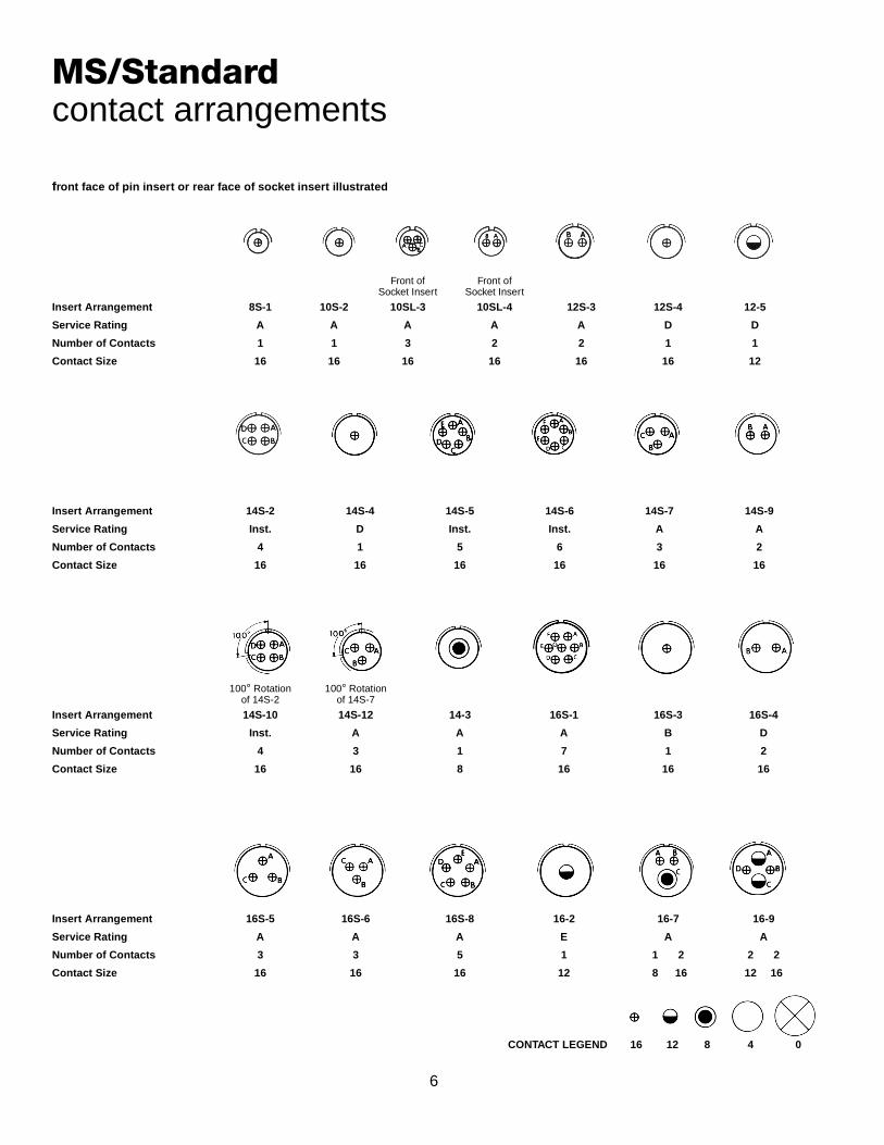
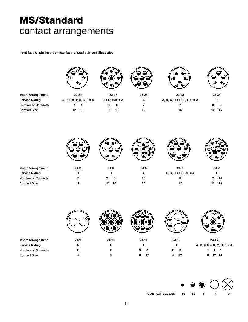
front face of pin insert or rear face of socket insert illustrated
MS/Standardcontact arrangements
Insert Arrangement 8S-1 10S-2 10SL-3 10SL-4 12S-3 12S-4 12-5
Service Rating A A A A A D D
Number of Contacts 1 1 3 2 2 1 1
Contact Size 16 16 16 16 16 16 12
Insert Arrangement 14S-2 14S-4 14S-5 14S-6 14S-7 14S-9
Service Rating Inst. D Inst. Inst. A A
Number of Contacts 4 1 5 6 3 2
Contact Size 16 16 16 16 16 16
Insert Arrangement 14S-10 14S-12 14-3 16S-1 16S-3 16S-4
Service Rating Inst. A A A B D
Number of Contacts 4 3 1 7 1 2
Contact Size 16 16 8 16 16 16
Insert Arrangement 16S-5 16S-6 16S-8 16-2 16-7 16-9
Service Rating A A A E A A
Number of Contacts 3 3 5 1 1 2 2 2
Contact Size 16 16 16 12 8 16 12 16
CONTACT LEGEND 16 12 8 4 0
Front ofSocket Insert
Front ofSocket Insert
100° Rotationof 14S-2
100° Rotationof 14S-7

7
front face of pin insert or rear face of socket insert illustrated
MS/Standardcontact arrangements
Insert Arrangement 16-10 16-11 16-12 16-13 18-1 18-3
Service Rating A A A A B, C, F, G = A; Bal. = Inst. D
Number of Contacts 3 2 1 2* 10 2
Contact Size 12 12 4 12 16 12
Insert Arrangement 18-4 18-5 18-6 18-7 18-8 18-9
Service Rating D D D B A Inst.
Number of Contacts 4 2 1 1 1 1 7 2 5
Contact Size 16 12 16 4 8 12 16 12 16
Insert Arrangement 18-10 18-11 18-12 18-13 18-14 18-15
Service Rating A A A A A A
Number of Contacts 4 5 6 1 3 1 1 4**
Contact Size 12 12 16 8 12 4 16 12
Insert Arrangement 18-16 18-17 18-19 18-20 18-22 18-24
Service Rating C Inst. A A D B, C, F, G = A; Bal. = Inst.
Number of Contacts 1 2 5 10 5 3 10
Contact Size 12 12 16 16 16 16 16
CONTACT LEGEND 16 12 8 4 0
* A = Iron; B = Constantan** A, C = Iron; B, D = Constantan
100° Rotationof 18-9
250° Rotationof 18-1

8
front face of pin insert or rear face of socket insert illustrated
MS/Standardcontact arrangements
Insert Arrangement 18-29 18-30 18-31 20-2 20-3 20-4
Service Rating A A A D D D
Number of Contacts 5 5 5 1 3 4
Contact Size 16 16 16 0 12 12
Insert Arrangement 20-6 20-7 20-8 20-9 20-11 20-12
Service Rating D A, B, H, G = D; C, D, E, F = A Inst. H = D; Bal. = A Inst. A
Number of Contacts 3 8 2 4 1 7 13 1 1
Contact Size 16 16 8 16 12 16 16 4 16
Insert Arrangement 20-14 20-15 20-16 20-17 20-18 20-19
Service Rating A A A A A A
Number of Contacts 2 3 7 2 7 5 1 3 6 3
Contact Size 8 12 12 12 16 12 16 12 16 8
CONTACT LEGEND 16 12 8 4 0
110° Rotationof 18-20
260° Rotationof 18-20

9
front face of pin insert or rear face of socket insert illustrated
MS/Standardcontact arrangements
Insert Arrangement 20-20 20-21 20-22 20-23 20-24 20-25
Service Rating A A A A A Inst.
Number of Contacts 1 3 1 8 3 3 2 2 2 13
Contact Size 4 12 12 16 8 16 8 8 16 16
Insert Arrangement 20-27 20-29 20-30 20-33 22-1 22-2
Service Rating A A Inst. A D D
Number of Contacts 14 17 13 11 2 3
Contact Size 16 16 16 16 8 8
Insert Arrangement 22-4 22-5 22-6 22-7 22-8
Service Rating A D D E E
Number of Contacts 2 2 2 4 2 1 1 2
Contact Size 8 12 12 16 8 16 0 12
CONTACT LEGEND 16 12 8 4 0
250° Rotationof 20-11
100° Rotationof 20-11

10
front face of pin insert or rear face of socket insert illustrated
MS/Standardcontact arrangements
Insert Arrangement 22-9 22-10 22-11 22-12 22-13
Service Rating E E B D E = D; A, B, C, D = A
Number of Contacts 3 4 2 2 3 4 1
Contact Size 12 16 16 8 16 12 16
Insert Arrangement 22-14 22-15 22-16 22-17 22-18
Service Rating A D = E; A, B, C, E, F = A A A = D; Bal. = A A, B, F, G, H = D; C, D, E = A
Number of Contacts 19 5 1 3 6 1 8 8
Contact Size 16 12 16 12 16 12 16 16
Insert Arrangement 22-19 22-20 22-21 22-22 22-23
Service Rating A A A A H = D; Bal. = A
Number of Contacts 14 9 1 2 4 8
Contact Size 16 16 0 16 8 12
CONTACT LEGEND 16 12 8 4 0
11
front face of pin insert or rear face of socket insert illustrated
MS/Standardcontact arrangements
Insert Arrangement 22-24 22-27 22-28 22-33 22-34
Service Rating C, D, E = D; A, B, F = A J = D; Bal. = A A A, B, C, D = D; E, F, G = A D
Number of Contacts 2 4 1 8 7 7 3 2
Contact Size 12 16 8 16 12 16 12 16
Insert Arrangement 24-2 24-3 24-5 24-6 24-7
Service Rating D D A A, G, H = D; Bal. = A A
Number of Contacts 7 2 5 16 8 2 14
Contact Size 12 12 16 16 12 12 16
Insert Arrangement 24-9 24-10 24-11 24-12 24-16
Service Rating A A A A A, B, F, G = D; C, D, E = A
Number of Contacts 2 7 3 6 2 3 1 3 3
Contact Size 4 8 8 12 4 12 8 12 16
CONTACT LEGEND 16 12 8 4 0
12
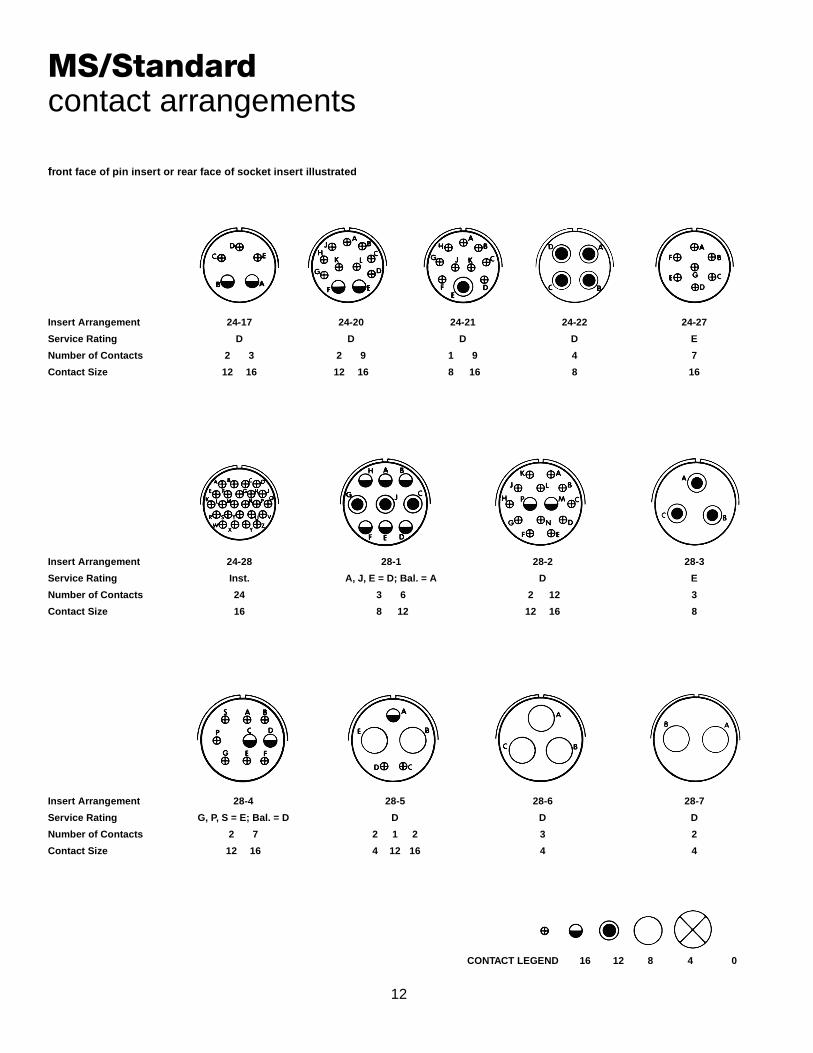
front face of pin insert or rear face of socket insert illustrated
MS/Standardcontact arrangements
Insert Arrangement 24-17 24-20 24-21 24-22 24-27
Service Rating D D D D E
Number of Contacts 2 3 2 9 1 9 4 7
Contact Size 12 16 12 16 8 16 8 16
Insert Arrangement 24-28 28-1 28-2 28-3
Service Rating Inst. A, J, E = D; Bal. = A D E
Number of Contacts 24 3 6 2 12 3
Contact Size 16 8 12 12 16 8
Insert Arrangement 28-4 28-5 28-6 28-7
Service Rating G, P, S = E; Bal. = D D D D
Number of Contacts 2 7 2 1 2 3 2
Contact Size 12 16 4 12 16 4 4
CONTACT LEGEND 16 12 8 4 0

13
front face of pin insert or rear face of socket insert illustrated
MS/Standardcontact arrangements
Insert Arrangement 28-8 28-9 28-10 28-11
Service Rating L, M = E; B = D; Bal. = A D G = D; Bal. = A A
Number of Contacts 2 10 6 6 2 2 3 4 18
Contact Size 12 16 12 16 4 8 12 12 16
Insert Arrangement 28-12 28-13 28-15 28-16
Service Rating A A A A
Number of Contacts 26 26 35 20
Contact Size 16 16 16 16
Insert Arrangement 28-17 28-18 28-19
Service Rating R = B; M, N, P = D; A to L = A M = C; G, H, J, K, L = D; A, B = A; Bal. = Inst. H, M = B; A, B = D; Bal. = A
Number of Contacts 15 12 4 6
Contact Size 16 16 12 16
CONTACT LEGEND 16 12 8 4 0
100° Rotationof 28-12

14
front face of pin insert or rear face of socket insert illustrated
MS/Standardcontact arrangements
Insert Arrangement 28-20 28-21 28-22 32-1
Service Rating A A D A = E; B, C, D, E = D
Number of Contacts 10 4 37 3 3 2 3
Contact Size 12 16 16 4 16 0 12
Insert Arrangement 32-2 32-3 32-4 32-5
Service Rating E D F, J, K, N = A; Bal. = D D
Number of Contacts 3 2 1 2 2 4 2 12 2
Contact Size 4 16 0 4 12 16 12 16 0
Insert Arrangement 32-6 32-7 32-8 32-9
Service Rating A A, B, h, j = Inst.; Bal. = A A D
Number of Contacts 2 3 2 16 7 28 6 24 2 12
Contact Size 4 8 12 16 12 16 12 16 4 16
CONTACT LEGEND 16 12 8 4 0

15
front face of pin insert or rear face of socket insert illustrated
MS/Standardcontact arrangements
Insert Arrangement 32-10 32-12 32-13 32-15
Service Rating A, F = E; G = B; B, E = D; C, D = A C, D, E, F, G = A; Bal. = D D D
Number of Contacts 2 2 3 5 10 5 18 2 6
Contact Size 4 8 16 12 16 12 16 0 12
Insert Arrangement 32-16 32-17 32-22 32-31
Service Rating A D A A
Number of Contacts 2 3 2 16 4 54 31
Contact Size 4 8 12 16 4 16 16
Insert Arrangement 36-1 36-3 36-4 36-5
Service Rating D D A = D; B, C = A A
Number of Contacts 4 18 3 3 3 4
Contact Size 12 16 0 12 0 0
CONTACT LEGEND 16 12 8 4 0
100° Rotationof 32-6

16
front face of pin insert or rear face of socket insert illustrated
MS/Standardcontact arrangements
Insert Arrangement 36-6 36-7 36-8 36-9
Service Rating A A A A
Number of Contacts 2 4 7 40 1 46 1 2 14 14
Contact Size 0 4 12 16 12 16 4 8 12 16
Insert Arrangement 36-10 36-11 36-12
Service Rating A A A
Number of Contacts 48 48 48
Contact Size 16 16 16
Insert Arrangement 36-13 36-14 36-15
Service Rating N, P, Q = E; Bal. = A D M = D; Bal. = A
Number of Contacts 2 15 5 5 6 35
Contact Size 12 16 8 12 16 16
CONTACT LEGEND 16 12 8 4 0
100° Rotationof 36-10
110° Rotationof 36-10
17
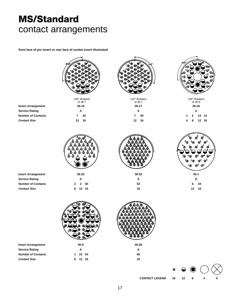
front face of pin insert or rear face of socket insert illustrated
MS/Standardcontact arrangements
Insert Arrangement 36-16 36-17 36-18
Service Rating A A A
Number of Contacts 7 40 7 40 1 2 14 14
Contact Size 12 16 12 16 4 8 12 16
Insert Arrangement 36-20 36-52 40-1
Service Rating A A D
Number of Contacts 2 2 30 52 6 24
Contact Size 8 12 16 16 12 16
Insert Arrangement 40-9 40-56
Service Rating A A
Number of Contacts 1 22 24 85
Contact Size 8 12 16 16
CONTACT LEGEND 16 12 8 4 0
110° Rotationof 36-7
100° Rotationof 36-9
100° Rotationof 36-7
18
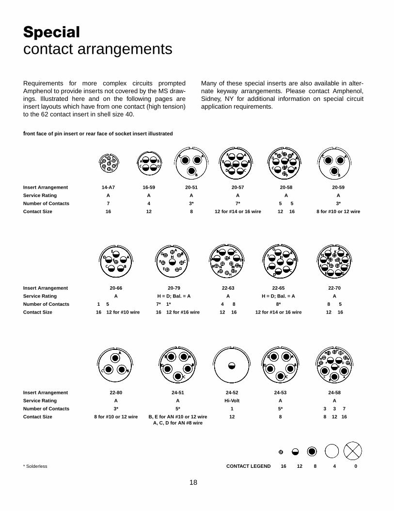
Specialcontact arrangements
Requirements for more complex circuits promptedAmphenol to provide inserts not covered by the MS draw-ings. Illustrated here and on the following pages areinsert layouts which have from one contact (high tension)to the 62 contact insert in shell size 40.
Many of these special inserts are also available in alter-nate keyway arrangements. Please contact Amphenol,Sidney, NY for additional information on special circuitapplication requirements.
front face of pin insert or rear face of socket insert illustrated
Insert Arrangement 14-A7 16-59 20-51 20-57 20-58 20-59
Service Rating A A A A A A
Number of Contacts 7 4 3* 7* 5 5 3*
Contact Size 16 12 8 12 for #14 or 16 wire 12 16 8 for #10 or 12 wire
Insert Arrangement 20-66 20-79 22-63 22-65 22-70
Service Rating A H = D; Bal. = A A H = D; Bal. = A A
Number of Contacts 1 5 7* 1* 4 8 8* 8 5
Contact Size 16 12 for #10 wire 16 12 for #16 wire 12 16 12 for #14 or 16 wire 12 16
Insert Arrangement 22-80 24-51 24-52 24-53 24-58
Service Rating A A Hi-Volt A A
Number of Contacts 3* 5* 1 5* 3 3 7
Contact Size 8 for #10 or 12 wire B, E for AN #10 or 12 wire 12 8 8 12 16A, C, D for AN #8 wire
* Solderless CONTACT LEGEND 16 12 8 4 0
19
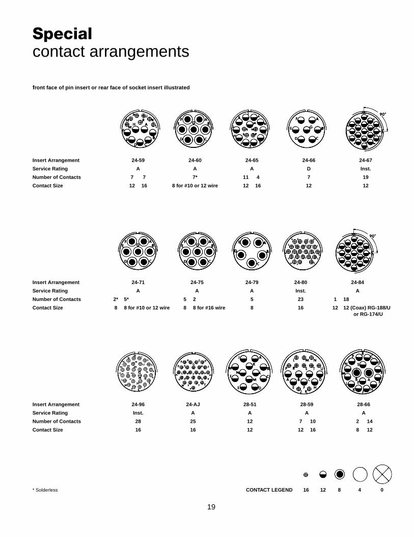
front face of pin insert or rear face of socket insert illustrated
Specialcontact arrangements
Insert Arrangement 24-59 24-60 24-65 24-66 24-67
Service Rating A A A D Inst.
Number of Contacts 7 7 7* 11 4 7 19
Contact Size 12 16 8 for #10 or 12 wire 12 16 12 12
Insert Arrangement 24-71 24-75 24-79 24-80 24-84
Service Rating A A A Inst. A
Number of Contacts 2* 5* 5 2 5 23 1 18
Contact Size 8 8 for #10 or 12 wire 8 8 for #16 wire 8 16 12 12 (Coax) RG-188/Uor RG-174/U
Insert Arrangement 24-96 24-AJ 28-51 28-59 28-66
Service Rating Inst. A A A A
Number of Contacts 28 25 12 7 10 2 14
Contact Size 16 16 12 12 16 8 12
* Solderless CONTACT LEGEND 16 12 8 4 0
20
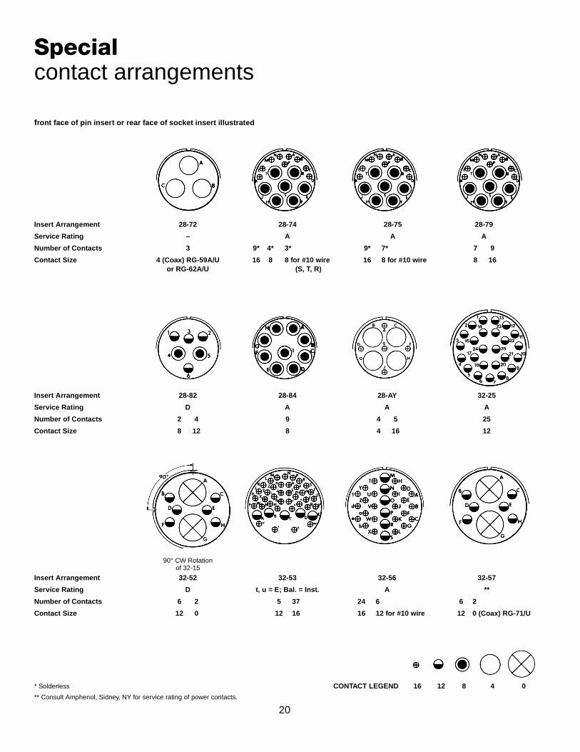
front face of pin insert or rear face of socket insert illustrated
Specialcontact arrangements
Insert Arrangement 28-72 28-74 28-75 28-79
Service Rating – A A A
Number of Contacts 3 9* 4* 3* 9* 7* 7 9
Contact Size 4 (Coax) RG-59A/U 16 8 8 for #10 wire 16 8 for #10 wire 8 16or RG-62A/U (S, T, R)
Insert Arrangement 28-82 28-84 28-AY 32-25
Service Rating D A A A
Number of Contacts 2 4 9 4 5 25
Contact Size 8 12 8 4 16 12
Insert Arrangement 32-52 32-53 32-56 32-57
Service Rating D t, u = E; Bal. = Inst. A **
Number of Contacts 6 2 5 37 24 6 6 2
Contact Size 12 0 12 16 16 12 for #10 wire 12 0 (Coax) RG-71/U
* Solderless CONTACT LEGEND 16 12 8 4 0
** Consult Amphenol, Sidney, NY for service rating of power contacts.
90° CW Rotationof 32-15

21
front face of pin insert or rear face of socket insert illustrated
Specialcontact arrangements
Insert Arrangement 32-58 32-60 32-62
Service Rating – A **
Number of Contacts 4 15 8 2 1 2 16 2
Contact Size 4 (Coax) RG-161/U 16 8 (Coax) RG-124/U 4 8 12 16 8 (Coax) RG-124/Uor RG-179/U
Insert Arrangement 36-64 32-68 32-73 32-75
Service Rating Inst. A A 8, 9 = D
Number of Contacts 54 12 4 46 2 7
Contact Size 16 16 4 (Coax) RG-58C/U 16 12 8 (Coax) RG-180B/U
Insert Arrangement 32-76 32-79 38-82 32-AF
Service Rating A D A A
Number of Contacts 19 4 1 4 12 55
Contact Size 12 4 8 4 16 16
** Consult Amphenol, Sidney, NY for service rating of power contacts. CONTACT LEGEND 16 12 8 4 0

22
front face of pin insert or rear face of socket insert illustrated
Specialcontact arrangements
Insert Arrangement 36-51 36-54 36-55
Service Rating D A A
Number of Contacts 2 2 8 31 31 8
Contact Size 0 4 8 16 16 8 for #6 wire
Insert Arrangement 36-59 36-60 36-64
Service Rating A ** –
Number of Contacts 50 3 40 7 4
Contact Size 16 12 for #10 wire 16 12 for #10 wire 0 (Coax) RG-11/U,RG-12/U or RG-13/U
Insert Arrangement 36-65 36-71 36-73
Service Rating – A –
Number of Contacts 4 3 50 7
Contact Size 0 (Coax) RG-59/U, RG-62/U 12 16 4 (Coax) RG-62B/Uor RG-71/U
** Consult Amphenol, Sidney, NY for service rating of power contacts. CONTACT LEGEND 16 12 8 4 0
23
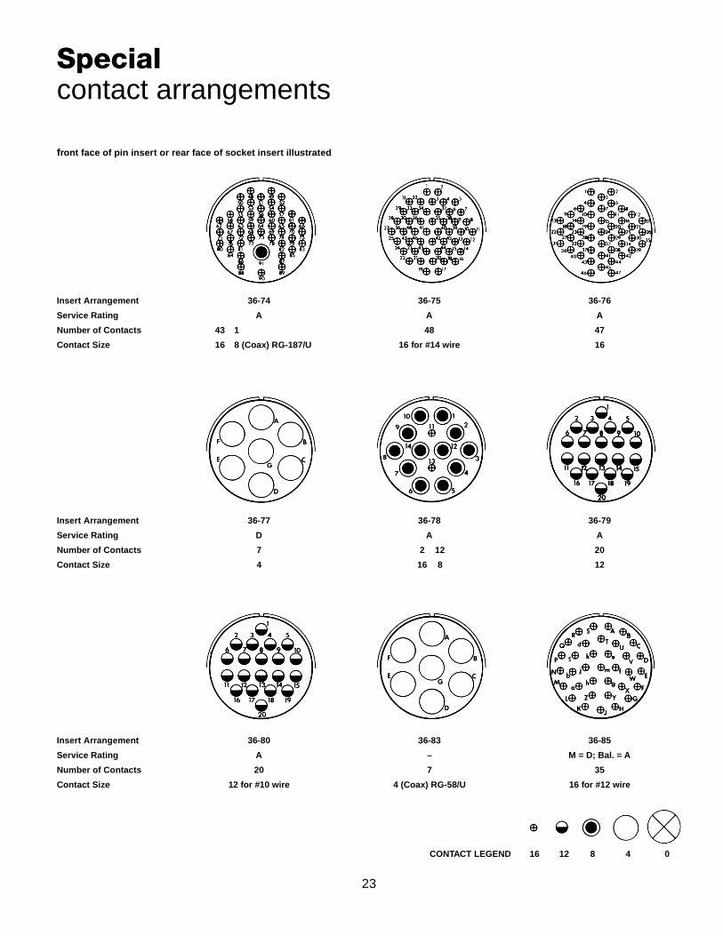
front face of pin insert or rear face of socket insert illustrated
Specialcontact arrangements
Insert Arrangement 36-74 36-75 36-76
Service Rating A A A
Number of Contacts 43 1 48 47
Contact Size 16 8 (Coax) RG-187/U 16 for #14 wire 16
Insert Arrangement 36-77 36-78 36-79
Service Rating D A A
Number of Contacts 7 2 12 20
Contact Size 4 16 8 12
Insert Arrangement 36-80 36-83 36-85
Service Rating A – M = D; Bal. = A
Number of Contacts 20 7 35
Contact Size 12 for #10 wire 4 (Coax) RG-58/U 16 for #12 wire
CONTACT LEGEND 16 12 8 4 0
24
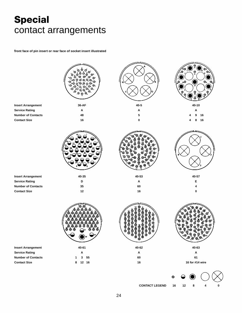
front face of pin insert or rear face of socket insert illustrated
Specialcontact arrangements
Insert Arrangement 36-AF 40-5 40-10
Service Rating A A A
Number of Contacts 48 5 4 9 16
Contact Size 16 0 4 8 16
Insert Arrangement 40-35 40-53 40-57
Service Rating D A E
Number of Contacts 35 60 4
Contact Size 12 16 0
Insert Arrangement 40-61 40-62 40-63
Service Rating A A A
Number of Contacts 1 3 55 60 61
Contact Size 8 12 16 16 16 for #14 wire
CONTACT LEGEND 16 12 8 4 0

25
front face of pin insert or rear face of socket insert illustrated
Specialcontact arrangements
Insert Arrangement 40-64 40-66 40-67
Service Rating – – A
Number of Contacts 3 20 13 4 1 10
Contact Size 12 16 8 (Coax) RG-124/U 0 (Coax) RG-63 B/U 16 4 (Coax) RG-59/U
Insert Arrangement 40-68 40-70 40-72
Service Rating A A A
Number of Contacts 21 61 1 10
Contact Size 8 16 16 4 (Coax) RG-9B/U
Insert Arrangement 40-73 40-74 40-75
Service Rating A A E
Number of Contacts 61 1 1 4 1 4
Contact Size 16 12 4 (Coax) RG-62/U 0 (Coax) RG-9B/U 12 0or RG-214/U
CONTACT LEGEND 16 12 8 4 0

26
front face of pin insert or rear face of socket insert illustrated
Specialcontact arrangements
Insert Arrangement 40-80 40-81 40-82
Service Rating A A A
Number of Contacts 1 10 62 62
Contact Size 16 4 16 for #14 wire 16
Insert Arrangement 40-85 40-86 40-87
Service Rating A – D
Number of Contacts 60 4 7
Contact Size 16 for #14 wire 0 (Coax) RG-115A/U 4
Insert Arrangement 40-AG
Service Rating A
Number of Contacts 38
Contact Size 12
CONTACT LEGEND 16 12 8 4 0
27
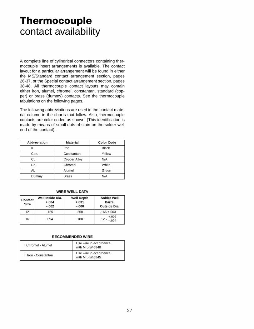
A complete line of cylindrical connectors containing ther-mocouple insert arrangements is available. The contactlayout for a particular arrangement will be found in eitherthe MS/Standard contact arrangement section, pages26-37, or the Special contact arrangement section, pages38-48. All thermocouple contact layouts may containeither iron, alumel, chromel, constantan, standard (cop-per) or brass (dummy) contacts. See the thermocoupletabulations on the following pages.
The following abbreviations are used in the contact mate-rial column in the charts that follow. Also, thermocouplecontacts are color coded as shown. (This identification ismade by means of small dots of stain on the solder wellend of the contact).
Abbreviation Material Color Code
Ir. Iron Black
Con. Constantan Yellow
Cu. Copper Alloy N/A
Ch. Chromel White
Al. Alumel Green
Dummy Brass N/A
WIRE WELL DATA
ContactSize
Well Inside Dia.+.004–.002
Well Depth+.031–.000
Solder WellBarrel
Outside Dia.
12 .125 .250 .166 ±.003
16 .094 .188 .125
RECOMMENDED WIRE
I Chromel - AlumelUse wire in accordancewith MIL-W-5848
II Iron - ConstantanUse wire in accordancewith MIL-W-5845
Thermocouplecontact availability
+.002–.004
28
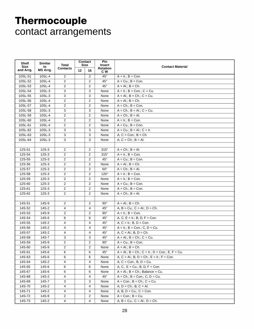
Shell Size
and Arrg.
Similar to
MS Arrg.
Total Contacts
ContactSize
Pin Insert
RotationC W
Contact Material12 16
10SL-51 10SL-4 2 2 45° A = Ir.; B = Con.
10SL-52 10SL-4 2 2 45° A = Cu.; B = Con.
10SL-53 10SL-4 2 2 45° A = Al.; B = Ch.
10SL-54 10SL-3 3 3 None A = Ir.; B = Con.; C = Cu.
10SL-55 10SL-3 3 3 None A = Al.; B = Ch.; C = Cu.
10SL-56 10SL-4 2 2 None A = Al.; B = Ch.
10SL-57 10SL-4 2 2 None A = Ch.; B = Con.
10SL-58 10SL-3 3 3 None A = Ch.; B = Al.; C = Cu.
10SL-59 10SL-4 2 2 None A = Ch.; B = Al.
10SL-60 10SL-4 2 2 None A = Ir.; B = Con.
10SL-61 10SL-4 2 2 None A = Cu.; B = Con.
10SL-62 10SL-3 3 3 None A = Cu.; B = Al.; C = Ir.
10SL-63 10SL-3 3 3 None A, C = Con.; B = Ch.
10SL-64 10SL-3 3 3 None A, C = Ch.; B = Al.
12S-51 12S-3 2 2 315° A = Ch.; B = Al.
12S-54 12S-3 2 2 315° A = Ir.; B = Con.
12S-55 12S-3 2 2 45° A = Cu.; B = Con.
12S-56 12S-3 2 2 None A = Al.; B = Ch.
12S-57 12S-3 2 2 60° A = Ch.; B = Al.
12S-58 12S-3 2 2 120° A = Ir.; B = Con.
12S-59 12S-3 2 2 None A = Ir.; B = Con.
12S-60 12S-3 2 2 None A = Cu.; B = Con.
12S-61 12S-3 2 2 None A = Ch.; B = Con.
12S-62 12S-3 2 2 None A = Ch.; B = Al.
14S-51 14S-9 2 2 90° A = Al.; B = Ch.
14S-52 14S-2 4 4 45° A, B = Cu.; C = Al.; D = Ch.
14S-53 14S-9 2 2 90° A = Ir.; B = Con.
14S-54 14S-6 6 6 45° A, C, E = Ir.; B, D, F = Con.
14S-55 14S-2 4 4 45° A, C = Ir.; B, D = Con.
14S-56 14S-2 4 4 45° A = Ir.; B = Con.; C, D = Cu.
14S-57 14S-2 4 4 45° A, C = Al.; B, D = Ch.
14S-58 14S-7 3 3 45° A = Al.; B = Ch.; C = Cu.
14S-59 14S-9 2 2 90° A = Cu.; B = Con.
14S-60 14S-9 2 2 None A = Al.; B = Ch.
14S-61 14S-6 6 6 45° A = Al.; B = Ch.; C = Ir.; D = Con.; E, F = Cu.
14S-63 14S-6 6 6 None A, C = Al.; B, D = Ch.; E = Ir.; F = Con.
14S-64 14S-2 4 4 None A, C = Con.; B, D = Cu.
14S-65 14S-6 6 6 None A, C., E = Cu.; B, D, F = Con.
14S-67 14S-6 6 6 None A = Al.; B = Ch.; Balance = Cu.
14S-68 14S-2 4 4 45° A = Ch.; B = Con.; C, D = Cu.
14S-69 14S-7 3 3 None A = Con.; B = Ch.; C = Cu.
14S-70 14S-2 4 4 None A, D = Ch.; B, C = Al.
14S-71 14S-2 4 4 None A, B, D = Cu.; C = Con.
14S-72 14S-9 2 2 None A = Con.; B = Cu.
14S-73 14S-2 4 4 None A, B = Cu.; C = Al.; D = Ch.
Thermocouplecontact arrangements

29
Thermocouplecontact arrangements
Shell Size
and Arrg.
Similar to
MS Arrg.
Total Contacts
ContactSize
Pin Insert
RotationC W
Contact Material12 16
14S-74 14S-2 4 4 None A, B = Ch.; C, D = Al.
14S-75 14S-2 4 4 None A, B = Cu.; C, D = Con.
14S-76 14S-2 4 4 None A, C = Al.; B, D = Ch.
14S-77 14S-2 4 4 None A, D = Al.; B, C = Ch.
14S-78 14S-9 2 2 None A = Ch.; B = Al.
16S-52 16S-4 2 2 None A = Ch.; B = Al.
16S-54 16S-1 7 7 None A = Al.; B = Ch.; Balance = Cu.
16S-55 16S-1 7 7 None A = Con.; Balance = Cu.
16-52 16-11 2 2 90° A = Al.; B = Ch.
16-53 16-9 4 2 2 70° A = Al.; C = Ch.; B, D = Cu.
16-55 16-10 3 3 45° A = Al.; B = Ch.; C = Cu.
16-56 16-13 2 2 90° A = Con.; B = Cu.
16-57 16-10 3 3 None A = Al.; B = Cu.; C = Ch.
16-58 16-10 3 3 None A = Con.; B, C = Cu.
16-60 16-13 2 2 None A = Al.; B = Ch.
16-62 16-11 2 2 None A = Con.; B = Cu.
18-51 18-12 6 6 None A = Ir.; B, E = Con.; D = Cu.; C, F = Dummy
18-52 18-11 5 5 None A = Ir.; B = Con.; C = Ch.; D = Al.; E = Dummy
18-53 18-12 6 6 None A, D = Ir.; B, E = Con.; C, F = Dummy
18-54 18-15 4 4 None A, C = Al.; B, D = Ch.
18-56 18-1 10 10 45° A, C, E, G, I = Ir.; B, D, F, H, J = Con.
18-57 18-12 6 6 45° A, C, E = Al.; B, D, F = Ch.
18-59 18-12 6 6 45° A, C = Ir.; B, E, F = Con.; D = Cu.
18-60 18-11 5 5 45° A, D = Al.; B, C, = Ch.; E = Cu.
18-61 18-12 6 6 None A, C = Ir.; B, D = Con.; E = Ch.; F = Al.
18-62 18-12 6 6 None A, B, C = Ir.; D, E, F = Con.
18-63 18-15 4 4 None A, C = Con.; B, D = Cu.
18-65 18-12 6 6 None A = Ir.; B = Con.; Balance = Cu.
18-66 18-1 10 10 None A, C, E, G, I = Cu.; B, D, F, H, J = Con.
18-67 18-12 6 6 None A, C, E = Cu.; B, D, F = Con.
18-68 18-11 5 5 None A, D = Al.; B, C = Ch.; E = Cu.
18-69 18-1 10 10 None A = Al.; B = Ch.; Balance = Cu.
18-70 18-11 5 5 None A = Ir.; B = Con.; C = Ch.; D = Al.; E = Cu.
18-71 18-15 4 4 None A = Con.; Balance = Cu.
18-72 18-15 4 4 None D = Con.; Balance = Cu.
18-73 18-9 7 2 5 None A = Al.; D = Ch.; Balance = Cu.
18-74 18-12 6 6 None A = Ch.; B = Al.; D = Ir.; E = Cu.; C, F = Con.
20-52 20-4 4 4 315° A = Ir.; B = Con.; C = Ch.; D = Al.
20-56 20-7 8 8 45° A, B, G, H = Ir.; C, D, E, F = Con.
20-60 20-7 8 8 45° D = Ch.; E = Al.; Balance = Cu.
20-61 20-29 17 17 45° A, B, M = Cu.; Balance = Con.
20-62 20-15 7 7 80° A, C, E = Al.; B, D, F = Ch.; G = Cu.
20-64 20-27 14 14 None A = Al.; C = Ch.; Balance = Cu.
30
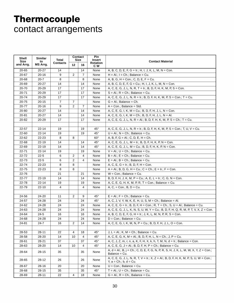
Thermocouplecontact arrangements
Shell Size
and Arrg.
Similar to
MS Arrg.
Total Contacts
ContactSize
Pin Insert
RotationC W
Contact Material12 16
20-65 20-27 14 14 None A, B, C, D, E, F, G = Ir.; H, I, J, K, L, M, N = Con.
20-67 20-16 9 2 7 None H = Al.; I = Ch.; Balance = Cu.
20-68 20-7 8 8 None A, B, G, H = Con.; C, D, E, F = Cu.
20-69 20-27 14 14 None A, B, C, D, E, F, G = Cu.; H, I, J, K, L, M, N = Con.
20-70 20-29 17 17 None A, C, E, G, J, L, N, R, T = Ir.; B, D, F, H, K, M, P, S = Con.
20-71 20-29 17 17 None S = Al.; R = Ch.; Balance = Cu.
20-74 20-29 17 17 None A, C, E, G, J, L, N, R = Ir.; B, D, F, H, K, M, P, S = Con.; T = Cu.
20-75 20-15 7 7 None G = Al.; Balance = Ch.
20-77 20-16 9 2 7 None A = Con.; Balance = Std.
20-80 20-27 14 14 None A, C, E, G, I, K, M = Cu.; B, D, F, H, J, L, N = Con.
20-81 20-27 14 14 None A, C, E, G, I, K, M = Ch.; B, D, F, H, J, L, N = Al.
20-82 20-29 17 17 None A, C, E, G, J, L, N, R = Al.; B, D, F, H, K, M, P, S = Ch.; T = Cu.
22-57 22-14 19 19 45° A, C, E, G, J, L, N, R = Ir.; B, D, F, H, K, M, P, S = Con.; T, U, V = Cu.
22-60 22-14 19 19 45° U = Al.; N = Ch.; Balance = Cu.
22-62 22-23 8 8 60° A, B, F, G = Al.; C, D, E, H = Ch.
22-68 22-19 14 14 45° A, C, E, G, J, L, M = Ir.; B, D, F, H, K, P, N = Con.
22-69 22-19 14 14 45° A, C, E, G, J, L, M = Cu.; B, D, F, H, K, P, N = Con.
22-71 22-14 19 19 None V = Al.; U = Ch.; Balance = Cu.
22-72 22-5 6 2 4 None B = Al.; E = Ch.; Balance = Cu.
22-73 22-5 6 2 4 None E = Al.; B = Ch.; Balance = Cu.
22-74 22-23 8 8 None A, C, E, G = Ir.; B, D, F, H = Con.
22-75 22-23 8 8 None A = Al.; B, D, G, H = Cu.; C = Ch.; E = Ir.; F = Con.
22-76 21 21 None W = Con.; Balance = Cu.
22-77 22-19 14 14 None B, D, F, H, J, K, M, P = Cu.; A, E, L = Ir.; C, G, N = Con.
22-78 22-14 19 19 None A, C, E, G, H, K, M, P, R, T = Con.; Balance = Cu.
22-79 22-10 4 4 None A, C, = Con.; B, D = Cu.
24-56 24-20 11 2 9 45° E = Al.; F = Ch.; Balance = Cu.
24-57 24-28 24 24 45° A, C, J, V, Y, W, K, E, H, U, S, M = Ch.; Balance = Al.
24-62 24-28 24 24 None A, C, E, G = Ir.; B, D, F, H = Con.; R, T = Ch.; S, U = Al.; Balance = Cu.
24-63 24-28 24 24 None A, C, E, G, J, L, K, N, S, U, W, Y = Cu.; B, D, F, H, Q, R, M, P, T, V, X, Z = Con.
24-64 24-5 16 16 None A, B, C, D, E, F, G, H = Ir.; J, K, L, M, N, P, R, S = Con.
24-68 24-28 24 24 None D = Con.; Balance = Cu.
24-81 24-7 16 2 14 None A, C, E, G, I, K, M, N, P = Cu.; B, D, F, H, J, L, O = Con.
28-53 28-11 22 4 18 45° J, L = Al.; K, M = Ch.; Balance = Cu.
28-58 28-20 14 10 4 45° A, C, E, G, K, M = Al.; B, D, F, H, L, N = Ch.; J, P = Cu.
28-61 28-21 37 37 45° A, C, J, Z, m, r, n, a, K, F, H, X, k, h, T, M, N, d = Ir.; Balance = Con.
28-63 28-20 14 10 4 45° A, C, E, G, J = Al.; B, D, F, H, P = Ch.; Balance = Cu.
28-64 28-15 35 35 None A, d = Al.; B, j = Ch.; C, D, E, F, G, N, P, R, S, H, J, K, L, M, W, X, Y, Z = Con.;Balance = Cu.
28-65 28-12 26 26 None A, C, E, G, J, L, N, R, T, V = Ir.; X, Z = Al.; B, D, F, H, K, M, P, S, U, W = Con.;Y, a = Ch.; b, d = Cu.
28-67 28-16 20 20 None U = Con.; Balance = Cu.
28-68 28-15 35 35 45° T = Al.; U = Ch.; Balance = Cu.
28-69 28-11 22 4 18 None G = Al.; R = Ch.; Balance = Cu.

31
Thermocouplecontact arrangements
* Amphenol arrangement
Shell Sizeand Arrg.
Similar toMS Arrg.
Total Contacts
ContactSize
Pin InsertRotation
C WContact Material
12 1628-70 28-11 22 4 18 None A = Al.; B = Ch.; Balance = Cu.
28-77 28-11 22 4 18 None J = Con.; Balance = Cu.
28-81 28-21 37 37 None A, D, S, Z, n, s = Ir.; B, J, K, f, g, r = Con.; G, L, P, b, e, j = Al.; F, H, T, X, h, k = Ch.; Balance = Cu.
32-51 32-8 30 6 24 90° M = Ch.; N = Al.; Balance = Cu.
32-55 32-8 30 6 24 125° M, N = Ch.; O, P = Al.; Balance = Cu.
36-53 36-7 47 7 40 45° u, v, w = Al.; x, y, z = Ch.; Balance = Cu.
36-56 36-10 48 48 None A, C, E, G, L, J, H, P, R, T, V, X Z, b, d, f, h, k, q, n, m, u, w, y = Con.;Balance = Cu.
36-57 36-8 47 1 46 None W = Al.; f = Ch. Balance = Cu.
36-58 36-15 35 35 None H = Al.; G = Ch.; Balance = Cu.
36-61 36-15 35 35 None A, C, E, J, K, L, M, N, P, R, T, V, f, X, Y, h, j, c = Con.; Balance = Cu.
36-62 36-10 48 48 None A, C, E, = Al.; B, D, F = Ch.; Balance = Cu.
36-82 36-52* 52 52 None v, g = Ir.; p, y, c = Con. x = Ch.; Balance = Cu.
40-58 40-56* 85 85 NoneA, C, E, H, K, M, P, S, U, W, Y, a, c, f, h, j, m, p, r, t, v, x, z, AB, AD, AF, AJ, AL, AN, AP, AS, AU, AW, AY, BA, BC, BE, BH, BK, BM, BP, BS, BU = Ir.; Balance = Con.
40-59 40-56* 85 85 None B = Ch.; C = Con.; Balance = Cu.
40-77 40-53* 60 60 None 55, 60 = Ir.; 57, 58, 59 = Con.; 56 = Ch.; Balance = Cu.
40-78 40-53* 60 60 None 50, 51 = Ir.; 27, 28, 29, 31, 32, 34, 36, 37 = Con.; 25, 39, 40, 41 = Al.;43, 44, 45, 46, 47, 48, 49, 52, 53, 54 = Ch.; Balance = Cu.

32
GTConnectorClasses

33
GT00Awall mount receptacle for front panel mounting
All dimensions for reference only.
Inches
ShellSize
BThread
Class 2AF
Min.K
Min.L
Max.
M+ .016– .000
N+ .000– .006
P± .008
R± .004
S± .012
T+ .004– .000
10SL .6250-24 UNEF .409 .374 1.969 .559 .717 .110 .717 1.000 .126
14S .7500-20 UNEF .520 .374 1.969 .559 .969 .126 .906 1.181 .126
16S .8750-20 UNEF .638 .374 1.969 .559 1.079 .126 .969 1.280 .126
16 .8750-20 UNEF .638 .374 2.362 .748 1.079 .126 .969 1.280 .126
18 1.0000-20 UNEF .756 .374 2.362 .748 1.213 .157 1.063 1.378 .126
20 1.1875-18 UNEF .867 .374 2.362 .748 1.346 .157 1.157 1.496 .126
22 1.1875-18 UNEF .965 .374 2.362 .748 1.472 .157 1.252 1.614 .126
24 1.4375-18 UNEF 1.094 .374 2.560 .811 1.610 .157 1.374 1.752 .146
28 1.4375-18 UNEF 1.228 .374 2.560 .811 1.839 .157 1.563 2.000 .146
32 1.7500-18 UNS 1.488 .433 2.560 .874 2.102 .157 1.752 2.244 .169
36 2.0000-18 UNS 1.780 .465 3.150 .874 2.346 .157 1.937 2.500 .169
40 2.2500-16 UN 2.016 .465 3.150 .874 2.579 .157 2.185 2.752 .169
Millimeters
ShellSize
FMin.
KMin.
LMax.
M+ 0.4– 0.0
N+ 0.00– 0.15
P± 0.2
R± 0.1
S± 0.3
T+ 0.1– 0.0
10SL 10.4 9.5 50 14.2 18.2 2.8 18.2 25.4 3.2
14S 13.2 9.5 50 14.2 24.6 3.2 23.0 30.0 3.2
16S 16.2 9.5 50 14.2 27.4 3.2 24.6 32.5 3.2
16 16.2 9.5 60 19.0 27.4 3.2 24.6 32.5 3.2
18 19.2 9.5 60 19.0 30.8 4.0 27.0 35.0 3.2
20 22.0 9.5 60 19.0 34.2 4.0 29.4 38.0 3.2
22 24.5 9.5 60 19.0 37.4 4.0 31.8 41.0 3.2
24 27.8 9.5 65 20.6 40.9 4.0 34.9 44.5 3.7
28 31.2 9.5 65 20.6 46.7 4.0 39.7 50.8 3.7
32 37.8 11.0 65 22.2 53.4 4.0 44.5 57.0 4.3
36 45.2 11.8 80 22.2 59.6 4.0 49.2 63.5 4.3
40 51.2 11.8 80 22.2 65.5 4.0 55.5 69.9 4.3
• Four through mounting holes or optional threaded holes• Includes backshell for accessory attachment• Without grommet and cable clamp• Non-environment proof

34
GT00AF/00Fwall mount receptacle for front panel mounting
All dimensions for reference only.
Inches
ShellSize
LMax.
M+ .016– .000
N+ .000– .006
P± .008
R± .004
S± .012
T+ .004– .000
ZMax.
KKMax.
LLMax.
10SL 2.362 .559 .717 .110 .717 1.000 .126 .220 .894 4.720
14S 2.440 .559 .969 .126 .906 1.181 .126 .312 1.083 4.720
16S 2.756 .559 1.079 .126 .969 1.280 .126 .437 1.181 4.720
16 2.756 .748 1.079 .126 .969 1.280 .126 .437 1.181 4.921
18 3.031 .748 1.213 .157 1.063 1.378 .126 .562 1.300 4.921
20 3.031 .748 1.346 .157 1.157 1.496 .126 .625 1.476 4.921
22 3.031 .748 1.472 .157 1.252 1.614 .126 .625 1.476 4.921
24 3.346 .811 1.610 .157 1.374 1.752 .146 .750 1.705 4.921
28 3.346 .811 1.839 .157 1.563 2.000 .146 .750 1.705 4.921
32 3.346 .874 2.102 .157 1.752 2.244 .169 .937 2.035 4.921
36 4.133 .874 2.346 .157 1.937 2.500 .169 1.250 2.283 5.315
40 5.118 .874 2.579 .157 2.185 2.752 .169 1.375 2.579 5.709
Millimeters
ShellSize
LMax.
M+ 0.4– 0.0
N+ 0.00– 0.15
P± 0.2
R± 0.1
S± 0.3
T+ 0.1– 0.0
ZMax.
KKMax.
LLMax.
10SL 60 14.2 18.2 2.8 18.2 25.4 3.2 5.58 22.7 120
14S 62 14.2 24.6 3.2 23.0 30.0 3.2 7.92 27.5 120
16S 70 14.2 27.4 3.2 24.6 32.5 3.2 11.09 30.0 120
16 70 19.0 27.4 3.2 24.6 32.5 3.2 11.09 30.0 125
18 77 19.0 30.8 4.0 27.0 35.0 3.2 14.27 33.0 125
20 77 19.0 34.2 4.0 29.4 38.0 3.2 15.87 37.5 125
22 77 19.0 37.4 4.0 31.8 41.0 3.2 15.87 37.5 125
24 85 20.6 40.9 4.0 34.9 44.5 3.7 19.05 43.3 125
28 85 20.6 46.7 4.0 39.7 50.8 3.7 19.05 43.3 125
32 85 22.2 53.4 4.0 44.5 57.0 4.3 23.79 51.7 125
36 105 22.2 59.6 4.0 49.2 63.5 4.3 31.75 58.0 135
40 130 22.2 65.5 4.0 55.5 69.9 4.3 34.92 65.5 145
GT00AF• Without grommet• Cable clamp included• Non-environment proof• Four through mounting holes or optional threaded holes
GT00F• With wire sealing grommet and cable clamp• For use with individual wires• Environment proof• Four through mounting holes or optional threaded holes

35
GT00CF/00CFZwall mount receptacle for front panel mountingGT00CF• Without individual wire sealing grommet• Environment proof• Four through mounting holes or optional threaded holes• Includes clamp to grip and seal jacketed cable
GT00CFZ• Same as GT00CF except: individual wire sealing grommet
included for added moisture protection• Environment proof• Four through mounting holes or optional threaded holes• Includes clamp to grip and seal jacketed cable
All dimensions for reference only.
Inches
ShellSize
LApprox.
M+ .016– .000
N+ .000– .006
P± .008
R± .004
S± .012
T+ .004– .000
Z
Open Closed
10SL 2.740 .559 .717 .110 .717 1.000 .126 .312 .094
14S 2.898 .559 .969 .126 .906 1.181 .126 .438 .230
16S 2.898 .559 1.079 .126 .969 1.280 .126 .531 .315
16 3.217 .748 1.079 .126 .969 1.280 .126 .531 .315
18 3.307 .748 1.213 .157 1.063 1.378 .126 .625 .378
20 3.311 .748 1.346 .157 1.157 1.496 .126 .748 .445
22 3.350 .748 1.472 .157 1.252 1.614 .126 .748 .445
24 3.484 .811 1.610 .157 1.374 1.752 .146 .937 .610
28 3.736 .811 1.839 .157 1.563 2.000 .146 .937 .610
32 4.142 .874 2.102 .157 1.752 2.244 .169 1.250 .921
36 4.390 .874 2.346 .157 1.937 2.500 .169 1.378 .921
40 4.988 .874 2.579 .157 2.185 2.752 .169 1.624 1.177
Millimeters
ShellSize
LApprox.
M+ 0.4– 0.0
N+ 0.00– 0.15
P± 0.2
R± 0.1
S± 0.3
T+ 0.1– 0.0
Z
Open Closed
10SL 69.6 14.2 18.2 2.8 18.2 25.4 3.2 7.93 2.38
14S 73.6 14.2 24.6 3.2 23.0 30.0 3.2 11.12 5.84
16S 73.6 14.2 27.4 3.2 24.6 32.5 3.2 13.48 8.00
16 81.7 19.0 27.4 3.2 24.6 32.5 3.2 13.48 8.00
18 84.0 19.0 30.8 4.0 27.0 35.0 3.2 15.87 9.60
20 84.1 19.0 34.2 4.0 29.4 38.0 3.2 19.00 11.30
22 85.1 19.0 37.4 4.0 31.8 41.0 3.2 19.00 11.30
24 88.5 20.6 40.9 4.0 34.9 44.5 3.7 23.80 15.50
28 94.9 20.6 46.7 4.0 39.7 50.8 3.7 23.80 15.50
32 105.9 22.2 53.4 4.0 44.5 57.0 4.3 31.75 23.40
36 111.5 22.2 59.6 4.0 49.2 63.5 4.3 35.00 23.40
40 126.7 22.2 65.5 4.0 55.5 69.9 4.3 41.25 29.90
36
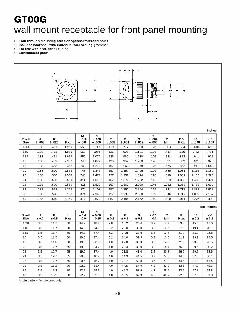
GT00Gwall mount receptacle for front panel mounting• Four through mounting holes or optional threaded holes• Includes backshell with individual wire sealing grommet• For use with heat-shrink tubing• Environment proof
All dimensions for reference only.
Inches
ShellSize
J± .008
K± .020
LMax.
M+ .016– .000
N+ .000– .006
P± .008
R± .004
S± .012
T+ .004– .000
ZMin.
BBMax.
JJ± .008
KK± .008
10SL .138 .461 1.969 .559 .717 .110 .717 1.000 .126 .303 .524 .610 .669
14S .138 .461 1.969 .559 .969 .126 .906 1.181 .126 .417 .669 .752 .791
16S .138 .461 1.969 .559 1.079 .126 .969 1.280 .126 .531 .862 .941 .925
16 .138 .453 2.362 .748 1.079 .126 .969 1.280 .126 .531 .862 .941 .925
18 .138 .453 2.362 .748 1.213 .157 1.063 1.378 .126 .575 .862 .941 1.043
20 .138 .500 2.559 .748 1.346 .157 1.157 1.496 .126 .736 1.031 1.165 1.189
22 .138 .500 2.559 .748 1.472 .157 1.252 1.614 .126 .819 1.031 1.165 1.323
24 .138 .500 2.559 .811 1.610 .157 1.374 1.752 .146 .969 1.358 1.488 1.421
28 .138 .500 2.559 .811 1.839 .157 1.563 2.000 .146 1.062 1.358 1.488 1.630
32 .138 .598 2.756 .874 2.102 .157 1.752 2.244 .169 1.311 1.717 1.882 1.913
36 .138 .598 3.150 .874 2.346 .157 1.937 2.500 .169 1.516 1.717 1.882 2.157
40 .138 .610 3.150 .874 2.579 1.57 2.185 2.752 .169 1.898 2.071 2.276 2.402
Millimeters
ShellSize
J± 0.2
K± 0.5
LMax.
M+ 0.4– 0.0
N+ 0.00– 0.15
P± 0.2
R± 0.1
S± 0.3
T+ 0.1– 0.0
ZMin.
BMax.
JJ± 0.2
KK± 0.2
10SL 3.5 11.7 50 14.2 18.2 2.8 18.2 25.4 3.2 7.7 13.3 15.5 17.0
14S 3.5 11.7 50 14.2 24.6 3.2 23.0 30.0 3.2 10.6 17.0 19.1 20.1
16S 3.5 11.7 50 14.2 27.4 3.2 24.6 32.5 3.2 13.5 21.9 23.9 23.5
16 3.5 11.5 60 19.0 27.4 3.2 24.6 32.5 3.2 13.5 21.9 23.9 23.5
18 3.5 11.5 60 19.0 30.8 4.0 27.0 35.0 3.2 14.6 21.9 23.9 26.5
20 3.5 12.7 65 19.0 34.2 4.0 29.4 38.0 3.2 18.7 26.2 29.6 30.2
22 3.5 12.7 65 19.0 37.4 4.0 31.8 41.0 3.2 20.8 26.2 29.6 33.6
24 3.5 12.7 65 20.6 40.9 4.0 34.9 44.5 3.7 24.6 34.5 37.8 36.1
28 3.5 12.7 65 20.6 46.7 4.0 39.7 50.8 3.7 27.0 34.5 37.8 41.4
32 3.5 15.2 70 22.2 53.4 4.0 44.5 57.0 4.3 33.3 43.6 47.8 48.6
36 3.5 15.2 80 22.2 59.6 4.0 49.2 63.5 4.3 38.5 43.6 47.8 54.8
40 3.5 15.5 80 22.2 65.5 4.0 55.5 69.9 4.3 48.2 52.6 57.8 61.0

37
GT00LCF/00LCFZwall mount receptacle for front panel mountingGT00LCF• Includes a backshell with extended length to provide
more working room for stripped jacketed cable• Environment proof• Four through mounting holes or optional threaded holes• Includes clamp to grip and seal jacketed cable
GT00LCFZ• Same as GT00LCF except: individual wire sealing grommet
included for added moisture protection• Environment proof• Four through mounting holes or optional threaded holes• Includes clamp to grip and seal jacketed cable
All dimensions for reference only.
Inches
ShellSize
LApprox.
M+ .016– .000
N+ .000– .006
P± .008
R± .004
S± .012
T+ .004– .000
Z
Open Closed
10SL 3.811 .559 .717 .110 .717 1.000 .126 .312 .094
14S 3.843 .559 .969 .126 .906 1.181 .126 .438 .230
16S 3.843 .559 1.079 .126 .969 1.280 .126 .531 .315
16 4.217 .748 1.079 .126 .969 1.280 .126 .531 .315
18 4.409 .748 1.213 .157 1.063 1.378 .126 .625 .378
20 4.409 .748 1.346 .157 1.157 1.496 .126 .748 .445
22 4.413 .748 1.472 .157 1.252 1.614 .126 .748 .445
24 4.535 .811 1.610 .157 1.374 1.752 .146 .937 .610
28 4.744 .811 1.839 .157 1.563 2.000 .146 .937 .610
32 5.079 .874 2.102 .157 1.752 2.244 .169 1.250 .921
36 5.327 .874 2.346 .157 1.937 2.500 .169 1.378 .921
40 5.327 .874 2.579 .157 2.185 2.752 .169 1.624 1.177
Millimeters
ShellSize
LApprox.
M+ 0.4– 0.0
N+ 0.00– 0.15
P± 0.2
R± 0.1
S± 0.3
T+ 0.1– 0.0
Z
Open Closed
10SL 96.8 14.2 18.2 2.8 18.2 25.4 3.2 7.93 2.38
14S 97.6 14.2 24.6 3.2 23.0 30.0 3.2 11.12 5.84
16S 97.6 14.2 27.4 3.2 24.6 32.5 3.2 13.48 8.00
16 107.1 19.0 27.4 3.2 24.6 32.5 3.2 13.48 8.00
18 112.0 19.0 30.8 4.0 27.0 35.0 3.2 15.87 9.60
20 112.0 19.0 34.2 4.0 29.4 38.0 3.2 19.00 11.30
22 112.1 19.0 37.4 4.0 31.8 41.0 3.2 19.00 11.30
24 115.2 20.6 40.9 4.0 34.9 44.5 3.7 23.80 15.50
28 120.5 20.6 46.7 4.0 39.7 50.8 3.7 23.80 15.50
32 129.0 22.2 53.4 4.0 44.5 57.0 4.3 31.75 23.40
36 135.3 22.2 59.6 4.0 49.2 63.5 4.3 35.00 23.40
40 135.3 22.2 65.5 4.0 55.5 69.9 4.3 41.25 29.90

38
GT00Rwall mount receptacle for front panel mounting• Four through mounting holes or optional threaded holes• With individual wire sealing grommet• Includes backshell for conduit termination• Environment proof
All dimensions for reference only.
Inches
ShellSize
BThread
Class 2AF
Min.K
Min.L
Max.
M+ .016– .000
N+ .000– .006
P± .008
R± .004
S± .012
T+ .004– .000
10SL .6250-24 UNEF .409 .374 1.969 .559 .717 .110 .717 1.000 .126
14S .7500-20 UNEF .520 .374 1.969 .559 .969 .126 .906 1.181 .126
16S .8750-20 UNEF .638 .374 1.969 .559 1.079 .126 .969 1.280 .126
16 .8750-20 UNEF .638 .374 2.362 .748 1.079 .126 .969 1.280 .126
18 1.0000-20 UNEF .756 .374 2.362 .748 1.213 .157 1.063 1.378 .126
20 1.1875-18 UNEF .866 .374 2.362 .748 1.346 .157 1.157 1.496 .126
22 1.1875-18 UNEF .965 .374 2.362 .748 1.472 .157 1.252 1.614 .126
24 1.4375-18 UNEF 1.094 .374 2.559 .811 1.610 .157 1.374 1.752 .146
28 1.4375-18 UNEF 1.228 .374 2.559 .811 1.839 .157 1.563 2.000 .146
32 1.7500-18 UNS 1.488 .433 2.559 .874 2.102 .157 1.752 2.244 .169
36 2.0000-18 UNS 1.780 .465 3.150 .874 2.346 .157 1.937 2.500 .169
40 2.2500-16 UN 2.016 .465 3.150 .874 2.579 .157 2.185 2.752 .169
Millimeters
ShellSize
FMin.
KMin.
LMax.
M+ 0.4– 0.0
N+ 0.00– 0.15
P± 0.2
R± 0.1
S± 0.3
T+ 0.1– 0.0
10SL 10.4 9.5 50 14.2 18.2 2.8 18.2 25.4 3.2
14S 13.2 9.5 50 14.2 24.6 3.2 23.0 30.0 3.2
16S 16.2 9.5 50 14.2 27.4 3.2 24.6 32.5 3.2
16 16.2 9.5 60 19.0 27.4 3.2 24.6 32.5 3.2
18 19.2 9.5 60 19.0 30.8 4.0 27.0 35.0 3.2
20 22.0 9.5 60 19.0 34.2 4.0 29.4 38.0 3.2
22 24.5 9.5 60 19.0 37.4 4.0 31.8 41.0 3.2
24 27.8 9.5 65 20.6 40.9 4.0 34.9 44.5 3.7
28 31.2 9.5 65 20.6 46.7 4.0 39.7 50.8 3.7
32 37.8 11.0 65 22.2 53.4 4.0 44.5 57.0 4.3
36 45.2 11.8 80 22.2 59.6 4.0 49.2 63.5 4.3
40 51.2 11.8 80 22.2 65.5 4.0 55.5 69.9 4.3
39
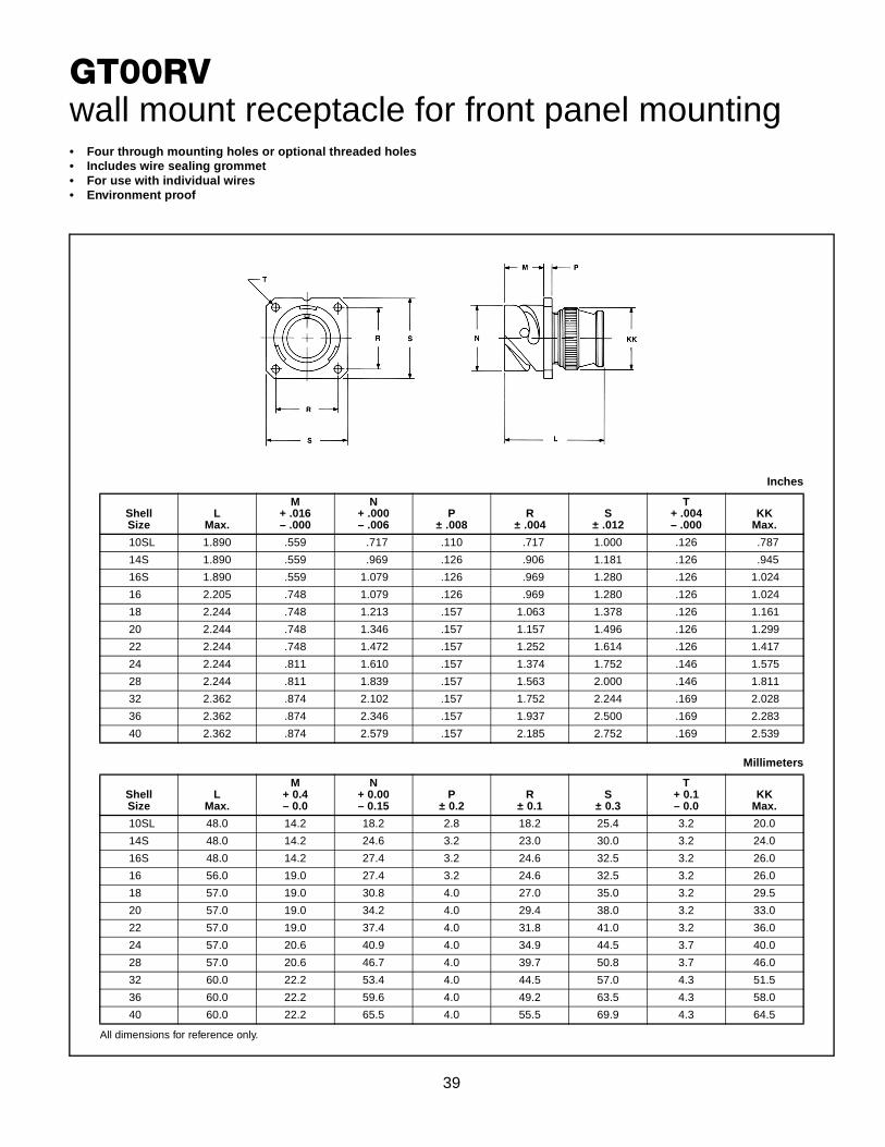
GT00RVwall mount receptacle for front panel mounting• Four through mounting holes or optional threaded holes• Includes wire sealing grommet• For use with individual wires• Environment proof
All dimensions for reference only.
Inches
ShellSize
LMax.
M+ .016– .000
N+ .000– .006
P± .008
R± .004
S± .012
T+ .004– .000
KKMax.
10SL 1.890 .559 .717 .110 .717 1.000 .126 .787
14S 1.890 .559 .969 .126 .906 1.181 .126 .945
16S 1.890 .559 1.079 .126 .969 1.280 .126 1.024
16 2.205 .748 1.079 .126 .969 1.280 .126 1.024
18 2.244 .748 1.213 .157 1.063 1.378 .126 1.161
20 2.244 .748 1.346 .157 1.157 1.496 .126 1.299
22 2.244 .748 1.472 .157 1.252 1.614 .126 1.417
24 2.244 .811 1.610 .157 1.374 1.752 .146 1.575
28 2.244 .811 1.839 .157 1.563 2.000 .146 1.811
32 2.362 .874 2.102 .157 1.752 2.244 .169 2.028
36 2.362 .874 2.346 .157 1.937 2.500 .169 2.283
40 2.362 .874 2.579 .157 2.185 2.752 .169 2.539
Millimeters
ShellSize
LMax.
M+ 0.4– 0.0
N+ 0.00– 0.15
P± 0.2
R± 0.1
S± 0.3
T+ 0.1– 0.0
KKMax.
10SL 48.0 14.2 18.2 2.8 18.2 25.4 3.2 20.0
14S 48.0 14.2 24.6 3.2 23.0 30.0 3.2 24.0
16S 48.0 14.2 27.4 3.2 24.6 32.5 3.2 26.0
16 56.0 19.0 27.4 3.2 24.6 32.5 3.2 26.0
18 57.0 19.0 30.8 4.0 27.0 35.0 3.2 29.5
20 57.0 19.0 34.2 4.0 29.4 38.0 3.2 33.0
22 57.0 19.0 37.4 4.0 31.8 41.0 3.2 36.0
24 57.0 20.6 40.9 4.0 34.9 44.5 3.7 40.0
28 57.0 20.6 46.7 4.0 39.7 50.8 3.7 46.0
32 60.0 22.2 53.4 4.0 44.5 57.0 4.3 51.5
36 60.0 22.2 59.6 4.0 49.2 63.5 4.3 58.0
40 60.0 22.2 65.5 4.0 55.5 69.9 4.3 64.5
40
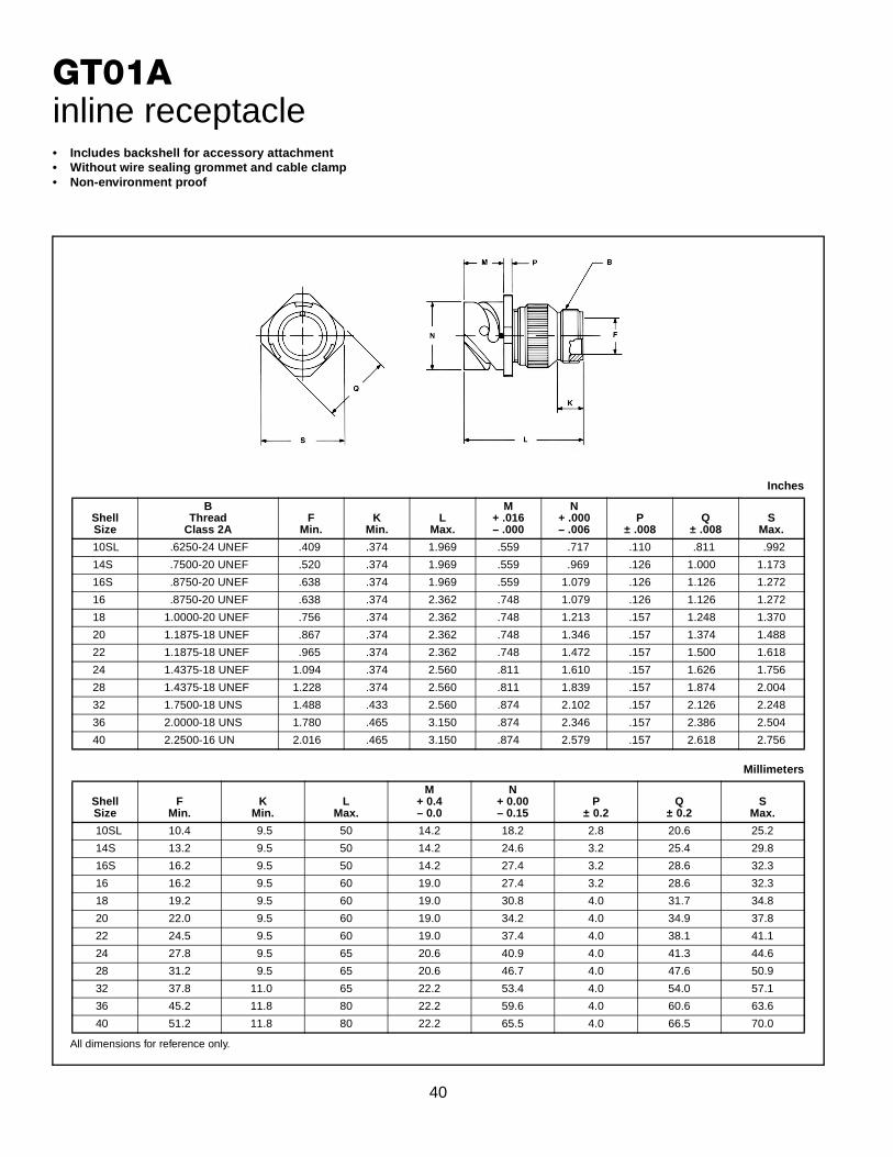
GT01Ainline receptacle• Includes backshell for accessory attachment• Without wire sealing grommet and cable clamp• Non-environment proof
All dimensions for reference only.
Inches
ShellSize
BThread
Class 2AF
Min.K
Min.L
Max.
M+ .016– .000
N+ .000– .006
P± .008
Q± .008
SMax.
10SL .6250-24 UNEF .409 .374 1.969 .559 .717 .110 .811 .992
14S .7500-20 UNEF .520 .374 1.969 .559 .969 .126 1.000 1.173
16S .8750-20 UNEF .638 .374 1.969 .559 1.079 .126 1.126 1.272
16 .8750-20 UNEF .638 .374 2.362 .748 1.079 .126 1.126 1.272
18 1.0000-20 UNEF .756 .374 2.362 .748 1.213 .157 1.248 1.370
20 1.1875-18 UNEF .867 .374 2.362 .748 1.346 .157 1.374 1.488
22 1.1875-18 UNEF .965 .374 2.362 .748 1.472 .157 1.500 1.618
24 1.4375-18 UNEF 1.094 .374 2.560 .811 1.610 .157 1.626 1.756
28 1.4375-18 UNEF 1.228 .374 2.560 .811 1.839 .157 1.874 2.004
32 1.7500-18 UNS 1.488 .433 2.560 .874 2.102 .157 2.126 2.248
36 2.0000-18 UNS 1.780 .465 3.150 .874 2.346 .157 2.386 2.504
40 2.2500-16 UN 2.016 .465 3.150 .874 2.579 .157 2.618 2.756
Millimeters
ShellSize
FMin.
KMin.
LMax.
M+ 0.4– 0.0
N+ 0.00– 0.15
P± 0.2
Q± 0.2
SMax.
10SL 10.4 9.5 50 14.2 18.2 2.8 20.6 25.2
14S 13.2 9.5 50 14.2 24.6 3.2 25.4 29.8
16S 16.2 9.5 50 14.2 27.4 3.2 28.6 32.3
16 16.2 9.5 60 19.0 27.4 3.2 28.6 32.3
18 19.2 9.5 60 19.0 30.8 4.0 31.7 34.8
20 22.0 9.5 60 19.0 34.2 4.0 34.9 37.8
22 24.5 9.5 60 19.0 37.4 4.0 38.1 41.1
24 27.8 9.5 65 20.6 40.9 4.0 41.3 44.6
28 31.2 9.5 65 20.6 46.7 4.0 47.6 50.9
32 37.8 11.0 65 22.2 53.4 4.0 54.0 57.1
36 45.2 11.8 80 22.2 59.6 4.0 60.6 63.6
40 51.2 11.8 80 22.2 65.5 4.0 66.5 70.0

41
GT01AF/01Finline receptacle
All dimensions for reference only.
Inches
ShellSize
LMax.
M+ .016– .000
N+ .000– .006
P± .008
Q± .008
SMax.
ZNominal
KKMax.
LLMax.
10SL 2.362 .559 .717 .110 .811 .992 .220 .894 4.720
14S 2.441 .559 .969 .126 1.000 1.173 .312 1.083 4.720
16S 2.756 .559 1.079 .126 1.126 1.272 .437 1.181 4.720
16 2.756 .748 1.079 .126 1.126 1.272 .437 1.181 4.921
18 3.031 .748 1.213 .157 1.248 1.370 .562 1.300 4.921
20 3.031 .748 1.346 .157 1.374 1.488 .625 1.476 4.921
22 3.031 .748 1.472 .157 1.500 1.618 .625 1.476 4.921
24 3.346 .811 1.610 .157 1.626 1.756 .750 1.705 4.921
28 3.346 .811 1.839 .157 1.874 2.004 .750 1.705 4.921
32 3.346 .874 2.102 .157 2.126 2.248 .937 2.035 4.921
36 4.134 .874 2.346 .157 2.386 2.504 1.250 2.283 5.315
40 5.118 .874 2.579 .157 2.618 2.756 1.375 2.579 5.709
Millimeters
ShellSize
LMax.
M+ 0.4– 0.0
N+ 0.00– 0.15
P± 0.2
Q± 0.2
SMax.
ZNominal
KKMax.
LLMax.
10SL 60 14.2 18.2 2.8 20.6 25.2 5.58 22.7 120
14S 62 14.2 24.6 3.2 25.4 29.8 7.92 27.5 120
16S 70 14.2 27.4 3.2 28.6 32.3 11.09 30.0 120
16 70 19.0 27.4 3.2 28.6 32.3 11.09 30.0 125
18 77 19.0 30.8 4.0 31.7 34.8 14.27 33.0 125
20 77 19.0 34.2 4.0 34.9 37.8 15.87 37.5 125
22 77 19.0 37.4 4.0 38.1 41.1 15.87 37.5 125
24 85 20.6 40.9 4.0 41.3 44.6 19.05 43.3 125
28 85 20.6 46.7 4.0 47.6 50.9 19.05 43.3 125
32 85 22.2 53.4 4.0 54.0 57.1 23.79 51.7 125
36 105 22.2 59.6 4.0 60.6 63.6 31.75 58.0 135
40 130 22.2 65.5 4.0 66.5 70.0 34.92 65.5 145
GT01AF• With cable clamp• Wire sealing grommet not included• Non-environment proof
GT01F• With wire sealing grommet and cable clamp• For use with individual wires• Environment proof

42
GT01Ginline receptacle• Includes wire sealing grommet• For use with heat-shrink tubing• Environment proof
All dimensions for reference only.
Inches
ShellSize
J± .008
K± .020
LMax.
M+ .016– .000
N+ .000– .006
P± .008
Q± .008
SMax.
ZMin.
BBMax.
JJ± .008
KK± .008
10SL .138 .461 1.969 .559 .717 .110 .811 .992 .303 .524 .610 .669
14S .138 .461 1.969 .559 .969 .126 1.000 1.173 .417 .669 .752 .791
16S .138 .461 1.969 .559 1.079 .126 1.126 1.272 .531 .862 .941 .925
16 .138 .453 2.362 .748 1.079 .126 1.126 1.272 .531 .862 .941 .925
18 .138 .453 2.362 .748 1.213 .157 1.248 1.370 .575 .862 .941 1.043
20 .138 .500 2.559 .748 1.346 .157 1.374 1.488 .736 1.031 1.165 1.189
22 .138 .500 2.559 .748 1.472 .157 1.500 1.618 .819 1.031 1.165 1.323
24 .138 .500 2.559 .811 1.610 .157 1.626 1.756 .969 1.358 1.488 1.421
28 .138 .500 2.559 .811 1.839 .157 1.874 2.004 1.063 1.358 1.488 1.630
32 .138 .598 2.756 .874 2.102 .157 2.126 2.248 1.311 1.717 1.882 1.913
36 .138 .598 3.150 .874 2.346 .157 2.386 2.504 1.516 1.717 1.882 2.157
40 .138 .610 3.150 .874 2.579 1.57 2.618 2.756 1.898 2.071 2.276 2.402
Millimeters
ShellSize
J± 0.2
K± 0.5
LMax.
M+ 0.4– 0.0
N+ 0.00– 0.15
P± 0.2
Q± 0.2
SMax.
ZMin.
BMax.
JJ± 0.2
KK± 0.2
10SL 3.5 11.7 50 14.2 18.2 2.8 20.6 25.2 7.7 13.3 15.5 17.0
14S 3.5 11.7 50 14.2 24.6 3.2 25.4 29.8 10.6 17.0 19.1 20.1
16S 3.5 11.7 50 14.2 27.4 3.2 28.6 32.3 13.5 21.9 23.9 23.5
16 3.5 11.5 60 19.0 27.4 3.2 28.6 32.3 13.5 21.9 23.9 23.5
18 3.5 11.5 60 19.0 30.8 4.0 31.7 34.8 14.6 21.9 23.9 26.5
20 3.5 12.7 65 19.0 34.2 4.0 34.9 37.8 18.7 26.2 29.6 30.2
22 3.5 12.7 65 19.0 37.4 4.0 38.1 41.1 20.8 26.2 29.6 33.6
24 3.5 12.7 65 20.6 40.9 4.0 41.3 44.6 24.6 34.5 37.8 36.1
28 3.5 12.7 65 20.6 46.7 4.0 47.6 50.9 27.0 34.5 37.8 41.4
32 3.5 15.2 70 22.2 53.4 4.0 54.0 57.1 33.3 43.6 47.8 48.6
36 3.5 15.2 80 22.2 59.6 4.0 60.6 63.6 38.5 43.6 47.8 54.8
40 3.5 15.5 80 22.2 65.5 4.0 66.5 70.0 48.2 52.6 57.8 61.0

43
GT01LCF/01LCFZinline receptacleGT01LCF• Long backshell provides more working room for
stripped jacketed cable• Includes cable clamp to grip and seal
jacketed cable• Environment proof
GT01LCFZ• Same as GT01LCF except: individual wire sealing grommet
included for added moisture protection• Environment proof
All dimensions for reference only.
Inches
ShellSize
LApprox.
M+ .016– .000
N+ .000– .006
P± .008
Q± .008
SMax.
Z
Open Closed
10SL 3.811 .559 .717 .110 .811 .992 .312 .094
14S 3.843 .559 .969 .126 1.000 1.173 .438 .230
16S 3.843 .559 1.079 .126 1.126 1.272 .531 .315
16 4.217 .748 1.079 .126 1.126 1.272 .531 .315
18 4.409 .748 1.213 .157 1.248 1.370 .625 .378
20 4.409 .748 1.346 .157 1.374 1.488 .748 .445
22 4.413 .748 1.472 .157 1.500 1.618 .748 .445
24 4.535 .811 1.610 .157 1.626 1.756 .937 .610
28 4.744 .811 1.839 .157 1.874 2.004 .937 .610
32 5.079 .874 2.102 .157 2.126 2.248 1.250 .921
36 5.327 .874 2.346 .157 2.386 2.504 1.378 .921
40 5.327 .874 2.579 .157 2.618 2.756 1.624 1.177
Millimeters
ShellSize
LApprox.
M+ 0.4– 0.0
N+ 0.00– 0.15
P± 0.2
Q± 0.2
SMax.
Z
Open Closed
10SL 96.8 14.2 18.2 2.8 20.6 25.2 7.93 2.38
14S 97.6 14.2 24.6 3.2 25.4 29.8 11.12 5.84
16S 97.6 14.2 27.4 3.2 28.6 32.3 13.48 8.00
16 107.1 19.0 27.4 3.2 28.6 32.3 13.48 8.00
18 112.0 19.0 30.8 4.0 31.7 34.8 15.87 9.60
20 112.0 19.0 34.2 4.0 34.9 37.8 19.00 11.30
22 112.1 19.0 37.4 4.0 38.1 41.1 19.00 11.30
24 115.2 20.6 40.9 4.0 41.3 44.6 23.80 15.50
28 120.5 20.6 46.7 4.0 47.6 50.9 23.80 15.50
32 129.0 22.2 53.4 4.0 54.0 57.1 31.75 23.40
36 135.3 22.2 59.6 4.0 60.6 63.6 35.00 23.40
40 135.3 22.2 65.5 4.0 66.5 70.0 41.25 29.90
44
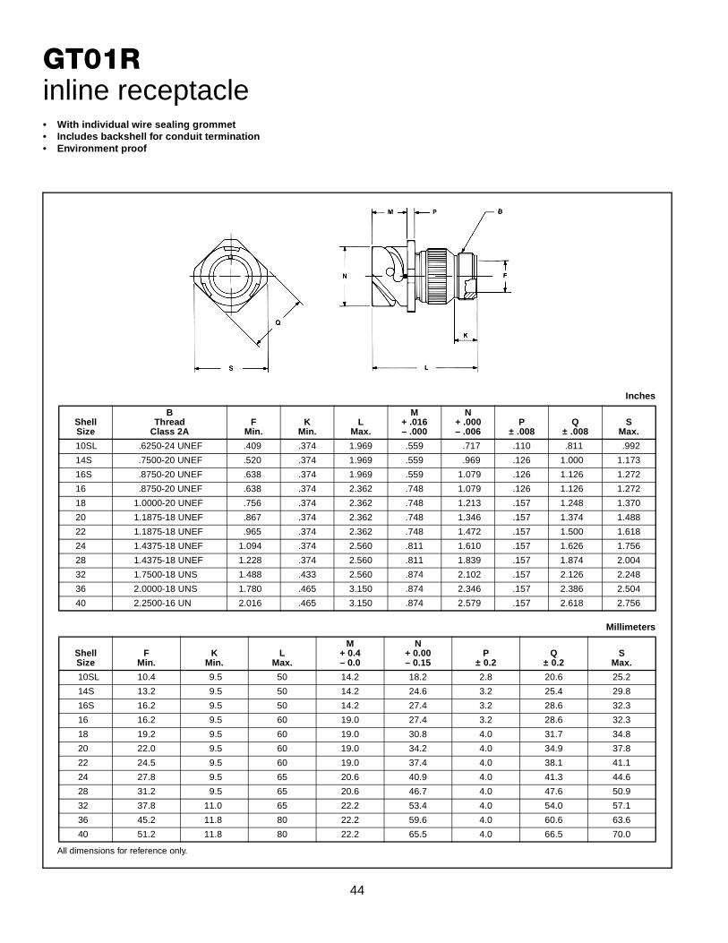
GT01Rinline receptacle• With individual wire sealing grommet• Includes backshell for conduit termination• Environment proof
All dimensions for reference only.
Inches
ShellSize
BThread
Class 2AF
Min.K
Min.L
Max.
M+ .016– .000
N+ .000– .006
P± .008
Q± .008
SMax.
10SL .6250-24 UNEF .409 .374 1.969 .559 .717 .110 .811 .992
14S .7500-20 UNEF .520 .374 1.969 .559 .969 .126 1.000 1.173
16S .8750-20 UNEF .638 .374 1.969 .559 1.079 .126 1.126 1.272
16 .8750-20 UNEF .638 .374 2.362 .748 1.079 .126 1.126 1.272
18 1.0000-20 UNEF .756 .374 2.362 .748 1.213 .157 1.248 1.370
20 1.1875-18 UNEF .867 .374 2.362 .748 1.346 .157 1.374 1.488
22 1.1875-18 UNEF .965 .374 2.362 .748 1.472 .157 1.500 1.618
24 1.4375-18 UNEF 1.094 .374 2.560 .811 1.610 .157 1.626 1.756
28 1.4375-18 UNEF 1.228 .374 2.560 .811 1.839 .157 1.874 2.004
32 1.7500-18 UNS 1.488 .433 2.560 .874 2.102 .157 2.126 2.248
36 2.0000-18 UNS 1.780 .465 3.150 .874 2.346 .157 2.386 2.504
40 2.2500-16 UN 2.016 .465 3.150 .874 2.579 .157 2.618 2.756
Millimeters
ShellSize
FMin.
KMin.
LMax.
M+ 0.4– 0.0
N+ 0.00– 0.15
P± 0.2
Q± 0.2
SMax.
10SL 10.4 9.5 50 14.2 18.2 2.8 20.6 25.2
14S 13.2 9.5 50 14.2 24.6 3.2 25.4 29.8
16S 16.2 9.5 50 14.2 27.4 3.2 28.6 32.3
16 16.2 9.5 60 19.0 27.4 3.2 28.6 32.3
18 19.2 9.5 60 19.0 30.8 4.0 31.7 34.8
20 22.0 9.5 60 19.0 34.2 4.0 34.9 37.8
22 24.5 9.5 60 19.0 37.4 4.0 38.1 41.1
24 27.8 9.5 65 20.6 40.9 4.0 41.3 44.6
28 31.2 9.5 65 20.6 46.7 4.0 47.6 50.9
32 37.8 11.0 65 22.2 53.4 4.0 54.0 57.1
36 45.2 11.8 80 22.2 59.6 4.0 60.6 63.6
40 51.2 11.8 80 22.2 65.5 4.0 66.5 70.0

45
GT01RVinline receptacle• Includes wire sealing grommet• For use with individual wires• Environment proof
All dimensions for reference only.
Inches
ShellSize
LMax.
M+ .016– .000
N+ .000– .006
P± .008
Q± .008
SMax.
KKMax.
10SL 1.890 .559 .717 .110 .811 .992 .787
14S 1.890 .559 .969 .126 1.000 1.173 .945
16S 1.890 .559 1.079 .126 1.126 1.272 1.024
16 2.205 .748 1.079 .126 1.126 1.272 1.024
18 2.244 .748 1.213 .157 1.248 1.370 1.161
20 2.244 .748 1.346 .157 1.374 1.488 1.299
22 2.244 .748 1.472 .157 1.500 1.618 1.417
24 2.244 .811 1.610 .157 1.626 1.756 1.575
28 2.244 .811 1.839 .157 1.874 2.004 1.811
32 2.362 .874 2.102 .157 2.126 2.248 2.028
36 2.362 .874 2.346 .157 2.386 2.504 2.283
40 2.362 .874 2.579 .157 2.618 2.756 2.539
Millimeters
ShellSize
LMax.
M+ 0.4– 0.0
N+ 0.00– 0.15
P± 0.2
Q± 0.2
SMax.
KKMax.
10SL 48.0 14.2 18.2 2.8 20.6 25.2 20.0
14S 48.0 14.2 24.6 3.2 25.4 29.8 24.0
16S 48.0 14.2 27.4 3.2 28.6 32.3 26.0
16 56.0 19.0 27.4 3.2 28.6 32.3 26.0
18 57.0 19.0 30.8 4.0 31.7 34.8 29.5
20 57.0 19.0 34.2 4.0 34.9 37.8 33.0
22 57.0 19.0 37.4 4.0 38.1 41.1 36.0
24 57.0 20.6 40.9 4.0 41.3 44.6 40.0
28 57.0 20.6 46.7 4.0 47.6 50.9 46.0
32 60.0 22.2 53.4 4.0 54.0 57.1 51.5
36 60.0 22.2 59.6 4.0 60.6 63.6 58.0
40 60.0 22.2 65.5 4.0 66.5 70.0 64.5
46
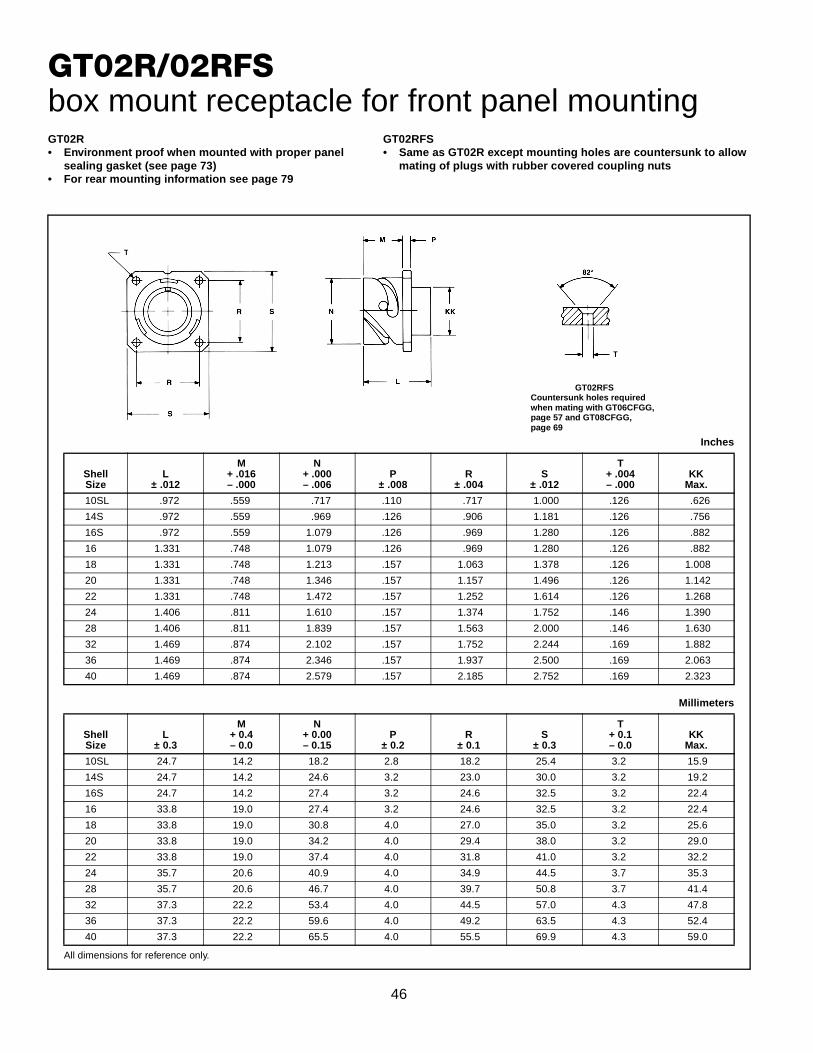
GT02R/02RFSbox mount receptacle for front panel mounting
All dimensions for reference only.
Inches
ShellSize
L± .012
M+ .016– .000
N+ .000– .006
P± .008
R± .004
S± .012
T+ .004– .000
KKMax.
10SL .972 .559 .717 .110 .717 1.000 .126 .626
14S .972 .559 .969 .126 .906 1.181 .126 .756
16S .972 .559 1.079 .126 .969 1.280 .126 .882
16 1.331 .748 1.079 .126 .969 1.280 .126 .882
18 1.331 .748 1.213 .157 1.063 1.378 .126 1.008
20 1.331 .748 1.346 .157 1.157 1.496 .126 1.142
22 1.331 .748 1.472 .157 1.252 1.614 .126 1.268
24 1.406 .811 1.610 .157 1.374 1.752 .146 1.390
28 1.406 .811 1.839 .157 1.563 2.000 .146 1.630
32 1.469 .874 2.102 .157 1.752 2.244 .169 1.882
36 1.469 .874 2.346 .157 1.937 2.500 .169 2.063
40 1.469 .874 2.579 .157 2.185 2.752 .169 2.323
Millimeters
ShellSize
L± 0.3
M+ 0.4– 0.0
N+ 0.00– 0.15
P± 0.2
R± 0.1
S± 0.3
T+ 0.1– 0.0
KKMax.
10SL 24.7 14.2 18.2 2.8 18.2 25.4 3.2 15.9
14S 24.7 14.2 24.6 3.2 23.0 30.0 3.2 19.2
16S 24.7 14.2 27.4 3.2 24.6 32.5 3.2 22.4
16 33.8 19.0 27.4 3.2 24.6 32.5 3.2 22.4
18 33.8 19.0 30.8 4.0 27.0 35.0 3.2 25.6
20 33.8 19.0 34.2 4.0 29.4 38.0 3.2 29.0
22 33.8 19.0 37.4 4.0 31.8 41.0 3.2 32.2
24 35.7 20.6 40.9 4.0 34.9 44.5 3.7 35.3
28 35.7 20.6 46.7 4.0 39.7 50.8 3.7 41.4
32 37.3 22.2 53.4 4.0 44.5 57.0 4.3 47.8
36 37.3 22.2 59.6 4.0 49.2 63.5 4.3 52.4
40 37.3 22.2 65.5 4.0 55.5 69.9 4.3 59.0
GT02RFSCountersunk holes requiredwhen mating with GT06CFGG,page 57 and GT08CFGG,page 69
GT02R• Environment proof when mounted with proper panel
sealing gasket (see page 73)• For rear mounting information see page 79
GT02RFS• Same as GT02R except mounting holes are countersunk to allow
mating of plugs with rubber covered coupling nuts

47
GT020R/020RFSMbox mount receptacle for front panel mounting
All dimensions for reference only.
Inches
ShellSize
BThread
Class 2AL
± .012
M+ .016– .000
N+ .000– .006
P± .008
R± .004
S± .012
T+ .004– .000
10SL .6250-24UNEF .972 .559 .717 .110 .717 1.000 .126
14S .7500-20UNEF .972 .559 .969 .126 .906 1.181 .126
16S .8750-20UNEF .972 .559 1.079 .126 .969 1.280 .126
16 .8750-20UNEF 1.331 .748 1.079 .126 .969 1.280 .126
18 1.0000-20UNEF 1.331 .748 1.213 .157 1.063 1.378 .126
20 1.1250-18UNEF 1.331 .748 1.346 .157 1.157 1.496 .126
22 1.2500-18UNEF 1.331 .748 1.472 .157 1.252 1.614 .126
24 1.3750-18UNEF 1.406 .811 1.610 .157 1.374 1.752 .146
28 1.6250-18UNEF 1.406 .811 1.839 .157 1.563 2.000 .146
32 1.8750-16UN 1.469 .874 2.102 .157 1.752 2.244 .169
36 2.0625-16UN 1.469 .874 2.346 .157 1.937 2.500 .169
40 2.3125-16UN 1.469 .874 2.579 .157 2.185 2.752 .169
Millimeters
ShellSize
L± 0.3
M+ 0.4– 0.0
N+ 0.00– 0.15
P± 0.2
R± 0.1
S± 0.3
T+ 0.1– 0.0
10SL 24.7 14.2 18.2 2.8 18.2 25.4 3.2
14S 24.7 14.2 24.6 3.2 23.0 30.0 3.2
16S 24.7 14.2 27.4 3.2 24.6 32.5 3.2
16 33.8 19.0 27.4 3.2 24.6 32.5 3.2
18 33.8 19.0 30.8 4.0 27.0 35.0 3.2
20 33.8 19.0 34.2 4.0 29.4 38.0 3.2
22 33.8 19.0 37.4 4.0 31.8 41.0 3.2
24 35.7 20.6 40.9 4.0 34.9 44.5 3.7
28 35.7 20.6 46.7 4.0 39.7 50.8 3.7
32 37.3 22.2 53.4 4.0 44.5 57.0 4.3
36 37.3 22.2 59.6 4.0 49.2 63.5 4.3
40 37.3 22.2 65.5 4.0 55.5 69.9 4.3
GT020R• Threaded rear to accept accessory hardware• Environment proof when mounted with proper
panel sealing gasket (see page 73)• For rear mounting information see page 79
GT020RFSM• Same as GT020R except mounting holes are countersunk
to allow mating of plugs with rubber covered coupling nuts
GT020RFSMCountersunk holes requiredwhen mating with GT06CFGG,page 57 and GT08CFGG,page 69

48
GT030square flange receptacle for rear panel mounting
All dimensions for reference only.
Inches
ShellSize
BThread
Class 2AL
± .012
M+ .016– .000
N+ .000– .006
P± .008
R± .004
S± .012
T+ .004– .000
10SL .6250-24UNEF 1.087 .717 .717 .110 .717 1.000 .126
14S .7500-20UNEF 1.087 .717 .969 .126 .906 1.181 .126
16S .8750-20UNEF 1.087 .717 1.079 .126 .969 1.280 .126
16 .8750-20UNEF 1.331 .846 1.079 .126 .969 1.280 .126
18 1.0000-20UNEF 1.331 .907 1.213 .157 1.063 1.378 .126
20 1.1250-18UNEF 1.331 .907 1.346 .157 1.157 1.496 .126
22 1.2500-18UNEF 1.331 .907 1.472 .157 1.252 1.614 .126
24 1.3750-18UNEF 1.331 .907 1.610 .157 1.374 1.752 .146
28 1.6250-18UNEF 1.406 .947 1.839 .157 1.563 2.000 .146
32 1.8750-16UN 1.469 .947 2.102 .157 1.752 2.244 .169
36 2.0625-16UN 1.469 .947 2.346 .157 1.937 2.500 .169
40 2.3125-16UN 1.469 .947 2.579 .157 2.185 2.752 .169
Millimeters
ShellSize
L± 0.3
M+ 0.4– 0.0
N+ 0.00– 0.15
P± 0.2
R± 0.1
S± 0.3
T+ 0.1– 0.0
10SL 27.6 18.2 18.2 2.8 18.2 25.4 3.2
14S 27.6 18.2 24.6 3.2 23.0 30.0 3.2
16S 27.6 18.2 27.4 3.2 24.6 32.5 3.2
16 33.8 21.5 27.4 3.2 24.6 32.5 3.2
18 33.8 23.05 30.8 4.0 27.0 35.0 3.2
20 33.8 23.05 34.2 4.0 29.4 38.0 3.2
22 33.8 23.05 37.4 4.0 31.8 41.0 3.2
24 33.8 23.05 40.9 4.0 34.9 44.5 3.7
28 35.7 24.05 46.7 4.0 39.7 50.8 3.7
32 37.3 24.05 53.4 4.0 44.5 57.0 4.3
36 37.3 24.05 59.6 4.0 49.2 63.5 4.3
40 37.3 24.05 65.5 4.0 55.5 69.9 4.3
• Four through mounting holes or optional threaded holes• Threaded rear to accept accessory attachment• Environment proof when mounted with a proper
sealing gasket (see page 73)

49
GT030Asquare flange receptacle for rear panel mounting• Four through mounting holes or optional threaded holes• Backshell included for accessory attachment• Without a wire sealing grommet and cable clamp• Non-environment proof
All dimensions for reference only.
Inches
ShellSize
BThread
Class 2AF
Min.K
Min.L
Max.
M+ .016– .000
N+ .000– .006
P± .008
R± .004
S± .012
T+ .004– .000
10SL .6250-24 UNEF .409 .374 1.969 .717 .717 .110 .717 1.000 .126
14S .7500-20 UNEF .520 .374 1.969 .717 .969 .126 .906 1.181 .126
16S .8750-20 UNEF .638 .374 1.969 .717 1.079 .126 .969 1.280 .126
16 .8750-20 UNEF .638 .374 2.362 .846 1.079 .126 .969 1.280 .126
18 1.0000-20 UNEF .756 .374 2.362 .907 1.213 .157 1.063 1.378 .126
20 1.1875-18 UNEF .867 .374 2.362 .907 1.346 .157 1.157 1.496 .126
22 1.1875-18 UNEF .965 .374 2.362 .907 1.472 .157 1.252 1.614 .126
24 1.4375-18 UNEF 1.094 .374 2.560 .907 1.610 .157 1.374 1.752 .146
28 1.4375-18 UNEF 1.228 .374 2.560 .947 1.839 .157 1.563 2.000 .146
32 1.7500-18 UNS 1.488 .433 2.560 .947 2.102 .157 1.752 2.244 .169
36 2.0000-18 UNS 1.780 .465 3.150 .947 2.346 .157 1.937 2.500 .169
40 2.2500-16 UN 2.016 .465 3.150 .947 2.579 .157 2.185 2.752 .169
Millimeters
ShellSize
FMin.
KMin.
LMax.
M+ 0.4– 0.0
N+ 0.00– 0.15
P± 0.2
R± 0.1
S± 0.3
T+ 0.1– 0.0
10SL 10.4 9.5 50 18.20 18.2 2.8 18.2 25.4 3.2
14S 13.2 9.5 50 18.20 24.6 3.2 23.0 30.0 3.2
16S 16.2 9.5 50 18.20 27.4 3.2 24.6 32.5 3.2
16 16.2 9.5 60 21.50 27.4 3.2 24.6 32.5 3.2
18 19.2 9.5 60 23.05 30.8 4.0 27.0 35.0 3.2
20 22.0 9.5 60 23.05 34.2 4.0 29.4 38.0 3.2
22 24.5 9.5 60 23.05 37.4 4.0 31.8 41.0 3.2
24 27.8 9.5 65 23.05 40.9 4.0 34.9 44.5 3.7
28 31.2 9.5 65 24.05 46.7 4.0 39.7 50.8 3.7
32 37.8 11.0 65 24.05 53.4 4.0 44.5 57.0 4.3
36 45.2 11.8 80 24.05 59.6 4.0 49.2 63.5 4.3
40 51.2 11.8 80 24.05 65.5 4.0 55.5 69.9 4.3
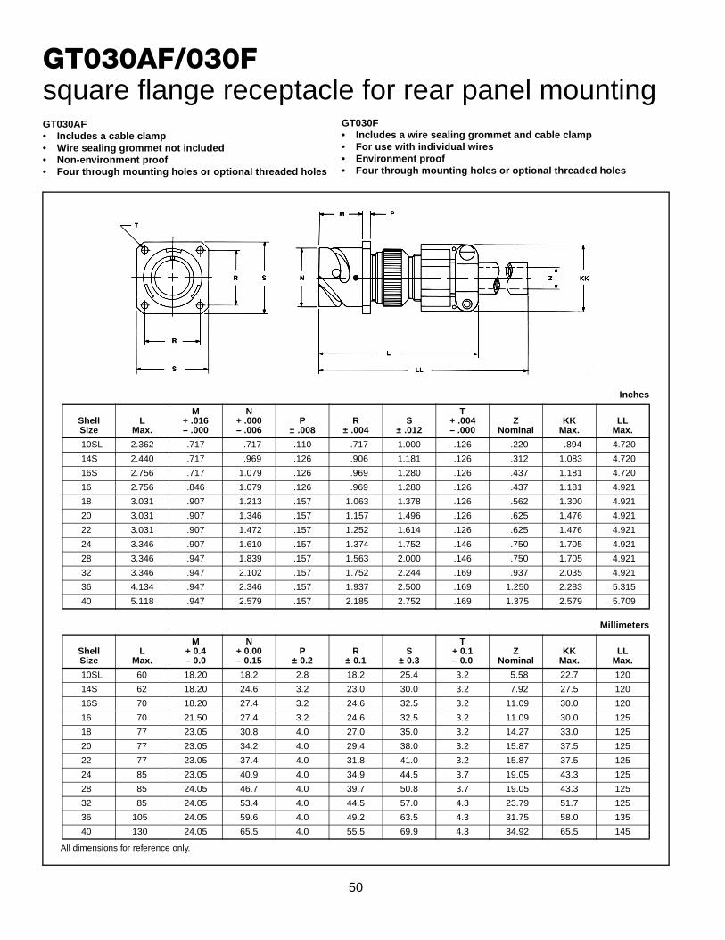
50
GT030AF/030Fsquare flange receptacle for rear panel mounting
All dimensions for reference only.
Inches
ShellSize
LMax.
M+ .016– .000
N+ .000– .006
P± .008
R± .004
S± .012
T+ .004– .000
ZNominal
KKMax.
LLMax.
10SL 2.362 .717 .717 .110 .717 1.000 .126 .220 .894 4.720
14S 2.440 .717 .969 .126 .906 1.181 .126 .312 1.083 4.720
16S 2.756 .717 1.079 .126 .969 1.280 .126 .437 1.181 4.720
16 2.756 .846 1.079 .126 .969 1.280 .126 .437 1.181 4.921
18 3.031 .907 1.213 .157 1.063 1.378 .126 .562 1.300 4.921
20 3.031 .907 1.346 .157 1.157 1.496 .126 .625 1.476 4.921
22 3.031 .907 1.472 .157 1.252 1.614 .126 .625 1.476 4.921
24 3.346 .907 1.610 .157 1.374 1.752 .146 .750 1.705 4.921
28 3.346 .947 1.839 .157 1.563 2.000 .146 .750 1.705 4.921
32 3.346 .947 2.102 .157 1.752 2.244 .169 .937 2.035 4.921
36 4.134 .947 2.346 .157 1.937 2.500 .169 1.250 2.283 5.315
40 5.118 .947 2.579 .157 2.185 2.752 .169 1.375 2.579 5.709
Millimeters
ShellSize
LMax.
M+ 0.4– 0.0
N+ 0.00– 0.15
P± 0.2
R± 0.1
S± 0.3
T+ 0.1– 0.0
ZNominal
KKMax.
LLMax.
10SL 60 18.20 18.2 2.8 18.2 25.4 3.2 5.58 22.7 120
14S 62 18.20 24.6 3.2 23.0 30.0 3.2 7.92 27.5 120
16S 70 18.20 27.4 3.2 24.6 32.5 3.2 11.09 30.0 120
16 70 21.50 27.4 3.2 24.6 32.5 3.2 11.09 30.0 125
18 77 23.05 30.8 4.0 27.0 35.0 3.2 14.27 33.0 125
20 77 23.05 34.2 4.0 29.4 38.0 3.2 15.87 37.5 125
22 77 23.05 37.4 4.0 31.8 41.0 3.2 15.87 37.5 125
24 85 23.05 40.9 4.0 34.9 44.5 3.7 19.05 43.3 125
28 85 24.05 46.7 4.0 39.7 50.8 3.7 19.05 43.3 125
32 85 24.05 53.4 4.0 44.5 57.0 4.3 23.79 51.7 125
36 105 24.05 59.6 4.0 49.2 63.5 4.3 31.75 58.0 135
40 130 24.05 65.5 4.0 55.5 69.9 4.3 34.92 65.5 145
GT030AF• Includes a cable clamp• Wire sealing grommet not included• Non-environment proof• Four through mounting holes or optional threaded holes
GT030F• Includes a wire sealing grommet and cable clamp• For use with individual wires• Environment proof• Four through mounting holes or optional threaded holes

51
GT030Gsquare flange receptacle for rear panel mounting• Four through mounting holes or optional threaded holes• With wire sealing grommet for individual wires• Includes backshell for use with heat-shrink tubing• Environment proof
All dimensions for reference only.
Inches
ShellSize
J± .008
K± .020
LMax.
M+ .016– .000
N+ .000– .006
P± .008
R± .004
S± .012
T+ .004– .000
ZMin.
BBMax.
JJ± .008
KK± .008
10SL .138 .461 1.969 .717 .717 .110 .717 1.000 .126 .303 .524 .610 .669
14S .138 .461 1.969 .717 .969 .126 .906 1.181 .126 .417 .669 .752 .791
16S .138 .461 1.969 .717 1.079 .126 .969 1.280 .126 .531 .862 .941 .925
16 .138 .453 2.362 .846 1.079 .126 .969 1.280 .126 .531 .862 .941 .925
18 .138 .453 2.362 .907 1.213 .157 1.063 1.378 .126 .575 .862 .941 1.043
20 .138 .500 2.559 .907 1.346 .157 1.157 1.496 .126 .736 1.031 1.165 1.189
22 .138 .500 2.559 .907 1.472 .157 1.252 1.614 .126 .819 1.031 1.165 1.323
24 .138 .500 2.559 .907 1.610 .157 1.374 1.752 .146 .969 1.358 1.488 1.421
28 .138 .500 2.559 .947 1.839 .157 1.563 2.000 .146 1.063 1.358 1.488 1.630
32 .138 .598 2.756 .947 2.102 .157 1.752 2.244 .169 1.311 1.717 1.882 1.913
36 .138 .598 3.150 .947 2.346 .157 1.937 2.500 .169 1.516 1.717 1.882 2.157
40 .138 .610 3.150 .947 2.579 1.57 2.185 2.752 .169 1.898 2.071 2.276 2.402
Millimeters
ShellSize
J± 0.2
K± 0.5
LMax.
M+ 0.4– 0.0
N+ 0.00– 0.15
P± 0.2
R± 0.1
S± 0.3
T+ 0.1– 0.0
ZMin.
BMax.
JJ± 0.2
KK± 0.2
10SL 3.5 11.7 50 18.20 18.2 2.8 18.2 25.4 3.2 7.7 13.3 15.5 17.0
14S 3.5 11.7 50 18.20 24.6 3.2 23.0 30.0 3.2 10.6 17.0 19.1 20.1
16S 3.5 11.7 50 18.20 27.4 3.2 24.6 32.5 3.2 13.5 21.9 23.9 23.5
16 3.5 11.5 60 21.50 27.4 3.2 24.6 32.5 3.2 13.5 21.9 23.9 23.5
18 3.5 11.5 60 23.05 30.8 4.0 27.0 35.0 3.2 14.6 21.9 23.9 26.5
20 3.5 12.7 65 23.05 34.2 4.0 29.4 38.0 3.2 18.7 26.2 29.6 30.2
22 3.5 12.7 65 23.05 37.4 4.0 31.8 41.0 3.2 20.8 26.2 29.6 33.6
24 3.5 12.7 65 23.05 40.9 4.0 34.9 44.5 3.7 24.6 34.5 37.8 36.1
28 3.5 12.7 65 24.05 46.7 4.0 39.7 50.8 3.7 27.0 34.5 37.8 41.4
32 3.5 15.2 70 24.05 53.4 4.0 44.5 57.0 4.3 33.3 43.6 47.8 48.6
36 3.5 15.2 80 24.05 59.6 4.0 49.2 63.5 4.3 38.5 43.6 47.8 54.8
40 3.5 15.5 80 24.05 65.5 4.0 55.5 69.9 4.3 48.2 52.6 57.8 61.0

52
GT030Rsquare flange receptacle for rear panel mounting• Four through mounting holes or optional threaded holes• With a wire sealing grommet for individual wires• Includes backshell for conduit termination• Environment proof
All dimensions for reference only.
Inches
ShellSize
BThread
Class 2AF
Min.K
Min.L
Max.
M+ .016– .000
N+ .000– .006
P± .008
R± .004
S± .012
T+ .004– .000
10SL .6250-24 UNEF .409 .374 1.969 .717 .717 .110 .717 1.000 .126
14S .7500-20 UNEF .520 .374 1.969 .717 .969 .126 .906 1.181 .126
16S .8750-20 UNEF .638 .374 1.969 .717 1.079 .126 .969 1.280 .126
16 .8750-20 UNEF .638 .374 2.362 .846 1.079 .126 .969 1.280 .126
18 1.0000-20 UNEF .756 .374 2.362 .907 1.213 .157 1.063 1.378 .126
20 1.1875-18 UNEF .867 .374 2.362 .907 1.346 .157 1.157 1.496 .126
22 1.1875-18 UNEF .965 .374 2.362 .907 1.472 .157 1.252 1.614 .126
24 1.4375-18 UNEF 1.094 .374 2.560 .907 1.610 .157 1.374 1.752 .146
28 1.4375-18 UNEF 1.228 .374 2.560 .947 1.839 .157 1.563 2.000 .146
32 1.7500-18 UNS 1.488 .433 2.560 .947 2.102 .157 1.752 2.244 .169
36 2.0000-18 UNS 1.780 .465 3.150 .947 2.346 .157 1.937 2.500 .169
40 2.2500-16 UN 2.016 .465 3.150 .947 2.579 .157 2.185 2.752 .169
Millimeters
ShellSize
FMin.
KMin.
LMax.
M+ 0.4– 0.0
N+ 0.00– 0.15
P± 0.2
R± 0.1
S± 0.3
T+ 0.1– 0.0
10SL 10.4 9.5 50 18.20 18.2 2.8 18.2 25.4 3.2
14S 13.2 9.5 50 18.20 24.6 3.2 23.0 30.0 3.2
16S 16.2 9.5 50 18.20 27.4 3.2 24.6 32.5 3.2
16 16.2 9.5 60 21.50 27.4 3.2 24.6 32.5 3.2
18 19.2 9.5 60 23.05 30.8 4.0 27.0 35.0 3.2
20 22.0 9.5 60 23.05 34.2 4.0 29.4 38.0 3.2
22 24.5 9.5 60 23.05 37.4 4.0 31.8 41.0 3.2
24 27.8 9.5 65 23.05 40.9 4.0 34.9 44.5 3.7
28 31.2 9.5 65 24.05 46.7 4.0 39.7 50.8 3.7
32 37.8 11.0 65 24.05 53.4 4.0 44.5 57.0 4.3
36 45.2 11.8 80 24.05 59.6 4.0 49.2 63.5 4.3
40 51.2 11.8 80 24.05 65.5 4.0 55.5 69.9 4.3

53
GT030RVsquare flange receptacle for rear panel mounting• Four through mounting holes or optional threaded holes• With wire sealing grommet for individual wires• Environment proof
All dimensions for reference only.
Inches
ShellSize
LMax.
M+ .016– .000
N+ .000– .006
P± .008
R± .004
S± .012
T+ .004– .000
KKMax.
10SL 1.890 .717 .717 .110 .717 1.000 .126 .787
14S 1.890 .717 .969 .126 .906 1.181 .126 .945
16S 1.890 .717 1.079 .126 .969 1.280 .126 1.024
16 2.205 .846 1.079 .126 .969 1.280 .126 1.024
18 2.244 .907 1.213 .157 1.063 1.378 .126 1.161
20 2.244 .907 1.346 .157 1.157 1.496 .126 1.299
22 2.244 .907 1.472 .157 1.252 1.614 .126 1.417
24 2.244 .907 1.610 .157 1.374 1.752 .146 1.575
28 2.244 .947 1.839 .157 1.563 2.000 .146 1.811
32 2.362 .947 2.102 .157 1.752 2.244 .169 2.028
36 2.362 .947 2.346 .157 1.937 2.500 .169 2.283
40 2.362 .947 2.579 .157 2.185 2.752 .169 2.539
Millimeters
ShellSize
LMax.
M+ 0.4– 0.0
N+ 0.00– 0.15
P± 0.2
R± 0.1
S± 0.3
T+ 0.1– 0.0
KKMax.
10SL 48.0 18.20 18.2 2.8 18.2 25.4 3.2 20.0
14S 48.0 18.20 24.6 3.2 23.0 30.0 3.2 24.0
16S 48.0 18.20 27.4 3.2 24.6 32.5 3.2 26.0
16 56.0 21.50 27.4 3.2 24.6 32.5 3.2 26.0
18 57.0 23.05 30.8 4.0 27.0 35.0 3.2 29.5
20 57.0 23.05 34.2 4.0 29.4 38.0 3.2 33.0
22 57.0 23.05 37.4 4.0 31.8 41.0 3.2 36.0
24 57.0 23.05 40.9 4.0 34.9 44.5 3.7 40.0
28 57.0 24.05 46.7 4.0 39.7 50.8 3.7 46.0
32 60.0 24.05 53.4 4.0 44.5 57.0 4.3 51.5
36 60.0 24.05 59.6 4.0 49.2 63.5 4.3 58.0
40 60.0 24.05 65.5 4.0 55.5 69.9 4.3 64.5

54
GT06Astraight plug
All dimensions for reference only.
Inches
ShellSize
BThread
Class 2AF
Min.K
Min.L
Max.Q
Max.
10SL .6250-24UNEF .409 .374 1.969 .898
14S .7500-20UNEF .520 .374 1.969 1.150
16S .8750-20UNEF .638 .374 1.969 1.260
16 .8750-20UNEF .638 .374 2.362 1.260
18 1.0000-20UNEF .756 .374 2.362 1.437
20 1.1875-18UNEF .867 .374 2.362 1.571
22 1.1875-18UNEF .965 .374 2.362 1.697
24 1.4375-18UNEF 1.094 .374 2.560 1.835
28 1.4375-18UNEF 1.228 .374 2.560 2.102
32 1.7500-18UNS 1.488 .433 2.560 2.366
36 2.0000-18UNS 1.780 .465 3.150 2.610
40 2.2500-16UN 2.016 .465 3.150 2.850
Millimeters
ShellSize
FMin.
KMin.
LMax.
QMax.
10SL 10.4 9.5 50 22.8
14S 13.2 9.5 50 29.2
16S 16.2 9.5 50 32.0
16 16.2 9.5 60 32.0
18 19.2 9.5 60 36.5
20 22.0 9.5 60 39.9
22 24.5 9.5 60 43.1
24 27.8 9.5 65 46.6
28 31.2 9.5 65 53.4
32 37.8 11.0 65 60.1
36 45.2 11.8 80 66.3
40 51.2 11.8 80 72.4
• Without grommet and cable clamp• If a cable clamp is required, see pages 76 and 78• Non-environment proof
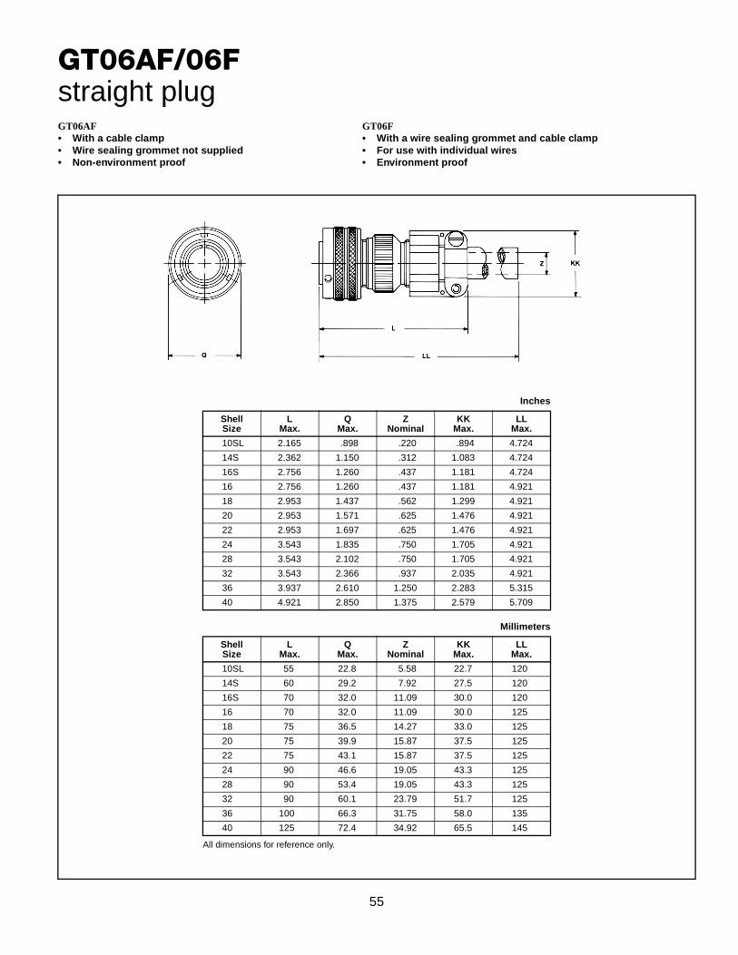
55
GT06AF/06Fstraight plug
All dimensions for reference only.
Inches
ShellSize
LMax.
QMax.
ZNominal
KKMax.
LLMax.
10SL 2.165 .898 .220 .894 4.724
14S 2.362 1.150 .312 1.083 4.724
16S 2.756 1.260 .437 1.181 4.724
16 2.756 1.260 .437 1.181 4.921
18 2.953 1.437 .562 1.299 4.921
20 2.953 1.571 .625 1.476 4.921
22 2.953 1.697 .625 1.476 4.921
24 3.543 1.835 .750 1.705 4.921
28 3.543 2.102 .750 1.705 4.921
32 3.543 2.366 .937 2.035 4.921
36 3.937 2.610 1.250 2.283 5.315
40 4.921 2.850 1.375 2.579 5.709
Millimeters
ShellSize
LMax.
QMax.
ZNominal
KKMax.
LLMax.
10SL 55 22.8 5.58 22.7 120
14S 60 29.2 7.92 27.5 120
16S 70 32.0 11.09 30.0 120
16 70 32.0 11.09 30.0 125
18 75 36.5 14.27 33.0 125
20 75 39.9 15.87 37.5 125
22 75 43.1 15.87 37.5 125
24 90 46.6 19.05 43.3 125
28 90 53.4 19.05 43.3 125
32 90 60.1 23.79 51.7 125
36 100 66.3 31.75 58.0 135
40 125 72.4 34.92 65.5 145
GT06AF• With a cable clamp• Wire sealing grommet not supplied• Non-environment proof
GT06F• With a wire sealing grommet and cable clamp• For use with individual wires• Environment proof

56
GT06CFstraight plug
All dimensions for reference only.
Inches
ShellSize
JApprox.
LApprox.
QMax.
Z
Open Closed
10SL .551 2.752 .898 .312 .094
14S .732 2.898 1.150 .438 .230
16S .732 2.898 1.260 .531 .315
16 .653 3.216 1.260 .531 .315
18 .705 3.307 1.437 .625 .378
20 .705 3.311 1.571 .748 .445
22 .744 3.350 1.697 .748 .445
24 .689 3.484 1.835 .937 .610
28 .921 3.736 2.102 .937 .610
32 1.016 4.142 2.366 1.250 .921
36 1.031 4.390 2.610 1.378 .921
40 1.614 4.640 2.854 1.624 1.177
Millimeters
ShellSize
JApprox.
LApprox.
QMax.
Z
Open Closed
10SL 14.0 69.6 22.8 7.93 2.38
14S 18.6 73.6 29.2 11.12 5.84
16S 18.6 73.6 32.0 13.48 8.00
16 16.6 81.7 32.0 13.48 8.00
18 17.9 84.0 36.5 15.87 9.60
20 17.9 84.1 39.9 19.00 11.30
22 18.9 85.1 43.1 19.00 11.30
24 17.5 88.5 46.6 23.80 15.50
28 23.4 94.9 53.4 23.80 15.50
32 25.8 105.2 60.1 31.75 23.40
36 26.2 111.5 66.3 35.00 23.40
40 41.0 111.5 72.5 41.25 29.90
• With a cable clamp and seal• For use with jacketed cable• Environment proof

57
GT06CFGGstraight plug• With rubber covered coupling nut for extreme shock
applications• The shrouded coupling nut protects the plug from damage• Provides a superior gripping surface• Seals the bayonet ramps
• Includes a backshell• Mates with GT020RFSM (see page 47)• Environment proof
All dimensions for reference only.
Inches
ShellSize
JApprox.
LApprox.
QMax.
SDia.
Z
Open Closed
10SL .551 3.150 1.319 1.122 .312 .094
18 .701 3.346 1.929 1.713 .625 .378
20 .705 3.937 2.028 1.811 .748 .445
22 .705 3.937 2.224 1.988 .748 .445
24 .689 4.016 2.362 2.126 .937 .610
28 .921 4.291 2.638 2.402 .937 .610
32 1.016 5.315 2.992 2.661 1.250 .921
36 1.031 5.039 3.240 2.925 1.378 .921
40 1.614 5.315 3.465 3.150 1.624 1.177
Millimeters
ShellSize
JApprox.
LApprox.
QMax.
SDia.
Z
Open Closed
10SL 14.0 80 33.5 28.5 7.93 2.38
18 17.8 85 49.0 43.5 15.87 9.60
20 17.9 100 51.5 46.0 19.00 11.30
22 17.9 100 56.5 50.5 19.00 11.30
24 17.5 102 60.0 54.0 23.80 15.50
28 23.4 109 67.0 61.0 23.80 15.50
32 25.6 135 76.0 67.6 31.75 23.40
36 26.2 128 82.3 74.3 35.00 23.40
40 41.0 135 88.0 80.0 41.25 29.90

58
GT06Gstraight plug• With a wire sealing grommet• For use with individual wires• Includes a backshell for use with heat-shrink tubing• Environment proof
All dimensions for reference only.
Inches
ShellSize
J± .008
K± .020
LMax.
QMax.
ZMin.
BBMax.
JJ± .008
KK± .008
10SL .138 .461 1.969 .898 .303 .524 .610 .669
14S .138 .461 1.969 1.150 .417 .669 .752 .791
16S .138 .461 1.969 1.260 .531 .862 .941 .925
16 .138 .453 2.362 1.260 .531 .862 .941 .925
18 .138 .453 2.362 1.437 .575 .862 .941 1.043
20 .138 .500 2.559 1.571 .736 1.031 1.165 1.189
22 .138 .500 2.559 1.697 .819 1.031 1.165 1.323
24 .138 .500 2.559 1.835 .969 1.358 1.488 1.421
28 .138 .500 2.559 2.102 1.063 1.358 1.488 1.630
32 .138 .598 2.756 2.366 1.311 1.717 1.882 1.913
36 .138 .598 3.150 2.610 1.516 1.717 1.882 2.157
40 .138 .610 3.150 2.854 1.898 2.071 2.276 2.402
Millimeters
ShellSize
J± 0.2
K± 0.5
LMax.
QMax.
ZMin.
BBMax.
JJ± 0.2
KK± 0.2
10SL 3.5 11.7 50 22.8 7.7 13.3 15.5 17.0
14S 3.5 11.7 50 29.2 10.6 17.0 19.1 20.1
16S 3.5 11.7 50 32.0 13.5 21.9 23.9 23.5
16 3.5 11.5 60 32.0 13.5 21.9 23.9 23.5
18 3.5 11.5 60 36.5 14.6 21.9 23.9 26.5
20 3.5 12.7 65 39.9 18.7 26.2 29.6 30.2
22 3.5 12.7 65 43.1 20.8 26.2 29.6 33.6
24 3.5 12.7 65 46.6 24.6 34.5 37.8 36.1
28 3.5 12.7 65 53.4 27.0 34.5 37.8 41.4
32 3.5 15.2 70 60.1 33.3 43.6 47.8 48.6
36 3.5 15.2 80 66.3 38.5 43.6 47.8 54.8
40 3.5 15.2 80 72.5 48.2 52.6 57.8 61.0

59
GT06LCstraight plug
All dimensions for reference only. * For example, typical part number would be:GTC06LC28-8PA59
Inches
ShellSize
LRef.
QMax.
Cable Range
AXX Part No. Suffix* Min. Max.
10SL 3.000 .898 A16 .250 .375
14S 3.000 1.150 A54 .375 .500
16S 3.000 1.260 A10 .500 .625
16 3.250 1.260 A12 .625 .750
18 3.250 1.437 A42 .750 .875
20 3.250 1.571 A11 .875 1.000
22 3.250 1.697 A55 1.000 1.125
24 3.250 1.835 A14 1.125 1.250
28 3.600 2.102 A56 1.250 1.375
32 3.600 2.366 A74 1.375 1.500
36 3.600 2.610 A57 1.500 1.625
40 3.600 2.854 A58 1.625 1.750
Millimeters
ShellSize
LRef.
QMax.
Cable Range
AXX Part No. Suffix* Min. Max.
10SL 76.2 22.8 A16 6.3 9.5
14S 76.2 29.2 A54 9.5 12.7
16S 76.2 32.0 A10 12.7 15.8
16 82.5 32.0 A12 15.8 19.0
18 82.5 36.4 A42 19.0 22.2
20 82.5 39.9 A11 22.2 25.4
22 82.5 43.1 A55 25.4 28.5
24 82.5 46.6 A14 28.5 31.7
28 91.4 53.3 A56 31.7 34.9
32 91.4 60.0 A74 34.9 38.1
36 91.4 66.2 A57 38.1 41.2
40 91.4 72.4 A58 41.2 44.4
• Includes a backshell with a basket weave strain relief cord grip• With a wire sealing grommet• Environment proof

60
GT06LCF/06LCFZstraight plug
All dimensions for reference only.
Inches
ShellSize
JApprox.
LApprox.
QMax.
Z
Open Closed
10SL 1.654 3.811 .898 .312 .094
14S 1.677 3.843 1.150 .438 .230
16S 1.677 3.843 1.260 .531 .315
16 1.677 4.217 1.260 .531 .315
18 1.803 4.409 1.437 .625 .378
20 1.807 4.409 1.571 .748 .445
22 1.807 4.413 1.697 .748 .445
24 1.752 4.535 1.835 .937 .610
28 1.949 4.756 2.102 .937 .610
32 1.953 5.079 2.366 1.250 .921
36 1.969 5.327 2.610 1.378 .921
40 1.969 5.327 2.854 1.624 1.177
Millimeters
ShellSize
JApprox.
LApprox.
QMax.
Z
Open Closed
10SL 42.0 96.8 22.8 7.93 2.38
14S 42.6 97.6 29.2 11.12 5.84
16S 42.6 97.6 32.0 13.48 8.00
16 42.6 107.1 32.0 13.48 8.00
18 45.8 112.0 36.5 15.87 9.60
20 45.9 112.0 39.9 19.00 11.30
22 45.9 112.1 43.1 19.00 11.30
24 44.5 115.2 46.6 23.80 15.50
28 49.5 120.8 53.4 23.80 15.50
32 49.6 129.0 60.1 31.75 23.40
36 50.0 135.3 66.3 35.00 23.40
40 50.0 135.3 72.5 41.25 29.90
GT06LCF• With cable clamp and seal• Long backshell provides more working room
for jacketed cable• Environment proof
GT06LCFZ• Same as GT06LCF except: Individual wire sealing
grommet for added moisture• Environment proof
GT06LCF• With cable clamp and seal• Long backshell provides more working room
for jacketed cable• Environment proof

61
GT06PP/064PPpanel plug
All dimensions for reference only.
Inches
ShellSize
LApprox.
QMax.
Q1
Max.P
± .008R
± .004S
± .012
T+ .004– .000
10SL 1.087 .898 .953 .110 .717 1.000 .126
14S 1.091 1.150 1.208 .126 .906 1.181 .126
16S 1.091 1.260 1.319 .126 .969 1.280 .126
16 1.469 1.260 1.319 .126 .969 1.280 .126
18 1.500 1.437 1.510 .157 1.063 1.378 .126
20 1.500 1.571 1.660 .157 1.157 1.496 .126
22 1.500 1.697 1.770 .157 1.252 1.614 .126
24 1.598 1.835 1.910 .157 1.374 1.752 .146
28 1.626 2.102 2.085 .157 1.563 2.000 .146
32 1.764 2.366 2.440 .157 1.752 2.244 .169
36 1.764 2.610 2.660 .157 1.937 2.500 .169
40 1.764 2.850 2.910 .157 2.185 2.752 .169
Millimeters
ShellSize
LApprox.
QMax.
Q1
Max.P
± 0.2R
± 0.1S
± 0.3
T+ 0.1– 0.0
10SL 27.6 22.8 24.2 2.8 18.2 25.4 3.2
14S 27.7 29.2 30.6 3.2 23.0 30.0 3.2
16S 27.7 32.0 33.5 3.2 24.6 32.5 3.2
16 37.3 32.0 33.5 3.2 24.6 32.5 3.2
18 38.1 36.5 38.3 4.0 27.0 35.0 3.2
20 38.1 39.9 42.1 4.0 29.4 38.0 3.2
22 38.1 43.1 44.9 4.0 31.8 41.0 3.2
24 40.6 46.6 48.5 4.0 34.9 44.5 3.7
28 41.3 53.4 52.9 4.0 39.7 50.8 3.7
32 44.8 60.1 61.9 4.0 44.5 57.0 4.3
36 44.8 66.3 67.5 4.0 49.2 63.5 4.3
40 44.8 72.4 73.9 4.0 55.5 69.9 4.3
GT06PP• Square flange mounting with four through holes• Environment proof with proper panel sealing gasket
(see page 73)
GT064PP• Square flange mounting with four through holes• Environment proof with proper panel sealing gasket
(see page 73)• Includes a heavy duty coupling nut
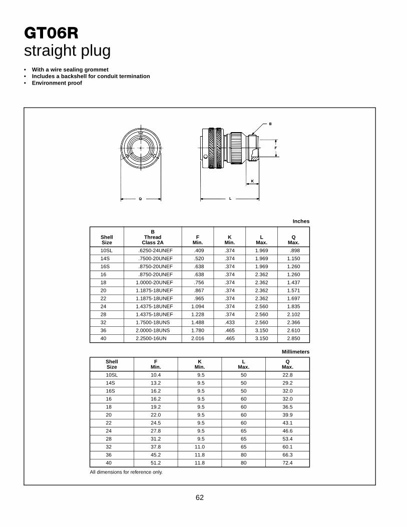
62
GT06Rstraight plug• With a wire sealing grommet• Includes a backshell for conduit termination• Environment proof
All dimensions for reference only.
Inches
ShellSize
BThread
Class 2AF
Min.K
Min.L
Max.Q
Max.
10SL .6250-24UNEF .409 .374 1.969 .898
14S .7500-20UNEF .520 .374 1.969 1.150
16S .8750-20UNEF .638 .374 1.969 1.260
16 .8750-20UNEF .638 .374 2.362 1.260
18 1.0000-20UNEF .756 .374 2.362 1.437
20 1.1875-18UNEF .867 .374 2.362 1.571
22 1.1875-18UNEF .965 .374 2.362 1.697
24 1.4375-18UNEF 1.094 .374 2.560 1.835
28 1.4375-18UNEF 1.228 .374 2.560 2.102
32 1.7500-18UNS 1.488 .433 2.560 2.366
36 2.0000-18UNS 1.780 .465 3.150 2.610
40 2.2500-16UN 2.016 .465 3.150 2.850
Millimeters
ShellSize
FMin.
KMin.
LMax.
QMax.
10SL 10.4 9.5 50 22.8
14S 13.2 9.5 50 29.2
16S 16.2 9.5 50 32.0
16 16.2 9.5 60 32.0
18 19.2 9.5 60 36.5
20 22.0 9.5 60 39.9
22 24.5 9.5 60 43.1
24 27.8 9.5 65 46.6
28 31.2 9.5 65 53.4
32 37.8 11.0 65 60.1
36 45.2 11.8 80 66.3
40 51.2 11.8 80 72.4

63
GT06RVstraight plug
All dimensions for reference only.
Inches
ShellSize
LMax.
QMax.
KKMax.
10SL 1.417 .898 .787
14S 1.437 1.150 .945
16S 1.437 1.260 1.024
16 1.929 1.260 1.024
18 1.929 1.437 1.161
20 1.969 1.571 1.299
22 1.969 1.697 1.417
24 2.008 1.835 1.543
28 2.008 2.102 1.811
32 2.087 2.366 2.028
36 2.106 2.610 2.283
40 2.126 2.850 2.539
Millimeters
ShellSize
LMax.
QMax.
KKMax.
10SL 36.0 22.8 20.0
14S 36.5 29.2 24.0
16S 36.5 32.0 26.0
16 49.0 32.0 26.0
18 49.0 36.5 29.5
20 50.0 39.9 33.0
22 50.0 43.1 36.0
24 51.0 46.6 40.0
28 51.0 53.4 46.0
32 53.0 60.1 51.5
36 53.5 66.3 58.0
40 54.0 72.4 64.5
• With a wire sealing grommet• For use with individual wires• Environment proof

64
GT065SL(*)straight plug
All dimensions for reference only. * Add suffix 1 or 2 for desired cable range.
Inches
ShellSize
LRef.
QMax.
Cable Range
(1)* (2)*
10SL 3.516 1.007 .11–.26 .07–.12
14S 3.628 1.259 .15–.32 .07–.24
16S 3.808 1.410 .19–.39 .11–.28
16 4.355 1.410 .19–.39 .11–.28
18 4.249 1.547 .23–.47 .19–.35
20 4.255 1.681 .39–.56 .27–.47
22 4.329 1.847 .51–.71 .35–.63
24 4.816 1.965 .51–.71 .35–.63
28 4.817 2.222 .70–.98 .51–.79
32 4.817 2.482 .86–1.26 .78–1.02
36 5.048 2.721 1.26–1.50 .98–1.22
40 4.978 2.953 1.45–1.75 1.14–1.38
Millimeters
ShellSize
LRef.
QMax.
Cable Range
(1)* (2)*
10SL 89.3 25.5 2.7–6.6 1.7–3.0
14S 92.1 31.9 3.8–8.1 1.7–6.0
16S 96.7 35.8 4.8–9.9 2.7–7.1
16 110.6 35.8 4.8–9.9 2.7–7.1
18 107.9 39.2 5.8–11.9 4.8–8.8
20 108.0 42.6 9.9–14.2 6.8–11.9
22 109.9 46.9 12.9–18.0 8.8–16.0
24 122.3 49.9 12.9–18.0 8.8–16.0
28 122.3 56.4 17.7–24.8 12.9–20.0
32 122.3 63.0 21.8–32.0 19.8–25.9
36 128.2 69.1 32.0–38.1 24.8–30.9
40 126.4 75.0 36.8–44.4 28.9–35.05
• Includes a long heavy duty coupling nut• Includes a liquid tight strain relief to grip and seal jacketed cable• Environment proof

65
GT07Rjam nut receptacle• For rear panel single hole mounting• Panel seal O-ring included• Environment proof
All dimensions for reference only.
Inches
ShellSize
BThread
Class 2AG
± .012
JWall Thickness M
± .012
N+ .000– .006
P± .007
R± .016
S± .012Min. Max.
10SL .8750-20 UNEF .441 .094 .205 .965 .717 .157 1.062 1.252
14S 1.1250-18 UNEF .575 .094 .295 1.055 .969 .189 1.312 1.626
16S 1.2500-18 UNEF .618 .094 .295 1.055 1.079 .189 1.500 1.748
16 1.2500-18 UNEF .618 .094 .295 1.264 1.079 .189 1.500 1.748
18 1.3750-18 UNEF .661 .094 .354 1.327 1.213 .189 1.562 1.874
20 1.5000-18 UNEF .709 .094 .358 1.327 1.346 .189 1.750 2.000
22 1.6250-18 UNEF .795 .094 .358 1.327 1.472 .189 2.000 2.252
24 1.7500-18 UNEF .795 .094 .358 1.327 1.610 .189 2.000 2.252
28 2.0000-18 UNS .886 .094 .394 1.386 1.839 .220 2.188 2.500
32 2.2500-16 UN .972 .094 .394 1.386 2.102 .220 2.438 2.748
36 2.5000-16 UN 1.059 .094 .327 1.386 2.346 .220 2.812 3.000
40 2.7500-16 UN 1.165 .094 .327 1.386 2.579 .220 3.000 3.248
Millimeters
ShellSize
G± 0.3
JWall Thickness M
± 0.3
N+ 0.00– 0.15
P± 0.2
R± 0.4
S± 0.3Min. Max.
10SL 11.2 2.4 5.2 24.5 18.2 4.0 27 31.8
14S 14.6 2.4 7.5 26.8 24.6 4.8 33 41.3
16S 15.7 2.4 7.5 26.8 27.4 4.8 38 44.4
16 15.7 2.4 7.5 32.1 27.4 4.8 38 44.4
18 16.8 2.4 9.0 33.7 30.8 4.8 40 47.6
20 18.0 2.4 9.1 33.7 34.2 4.8 44 50.8
22 20.2 2.4 9.1 33.7 37.4 4.8 51 57.2
24 20.2 2.4 9.1 33.7 40.9 4.8 51 57.2
28 22.5 2.4 10.0 35.2 46.7 5.6 56 63.5
32 24.7 2.4 10.0 35.2 53.4 5.6 62 69.8
36 26.9 2.4 8.3 35.2 59.6 5.6 71 76.2
40 29.6 2.4 8.3 35.2 65.5 5.6 76 82.5

66
GT070jam nut receptacle• For rear panel single hole mounting• Threaded rear for accessories• Environment proof
All dimensions for reference only.
Inches
ShellSize
BThread
Class 2AG
± .012
JWall Thickness L
± .010M
± .012
N+ .000– .006
P± .007
R± .016
S± .012
BBThread
Class 2AMin. Max.
10SL .8750-20 UNEF .441 .094 .205 1.425 .965 .717 .157 1.062 1.252 .6250-24 UNEF
14S 1.1250-18 UNEF .575 .094 .295 1.531 1.055 .969 .189 1.312 1.626 .7500-20 UNEF
16S 1.2500-18 UNEF .618 .094 .295 1.531 1.055 1.079 .189 1.500 1.748 .8750-20 UNEF
16 1.2500-18 UNEF .618 .094 .295 1.909 1.264 1.079 .189 1.500 1.748 .8750-20 UNEF
18 1.3750-18 UNEF .661 .094 .354 1.941 1.327 1.213 .189 1.562 1.874 1.0000-20 UNEF
20 1.5000-18 UNEF .709 .094 .358 1.941 1.327 1.346 .189 1.750 2.000 1.1250-18 UNEF
22 1.6250-18 UNEF .795 .094 .358 1.941 1.327 1.472 .189 2.000 2.252 1.2500-18 UNEF
24 1.7500-18 UNEF .795 .094 .358 1.953 1.327 1.610 .189 2.000 2.252 1.3750-18 UNEF
28 2.0000-18 UNS .886 .094 .394 2.043 1.386 1.839 .220 2.188 2.500 1.6250-18 UNEF
32 2.2500-16 UN .972 .094 .394 2.043 1.386 2.102 .220 2.438 2.748 1.8750-16 UN
36 2.5000-16 UN 1.059 .094 .327 2.043 1.386 2.346 .220 2.812 3.000 2.0625-16 UN
40 2.7500-16 UN 1.165 .094 .327 2.043 1.386 2.579 .220 3.000 3.248 2.3125-16 UN
Millimeters
ShellSize
G± 0.3
JWall Thickness l
± 0.3M
± 0.3
N+ 0.00– 0.15
P± 0.2
R± 0.4
S± 0.3Min. Max.
10SL 11.2 2.4 5.2 36.2 24.5 18.2 4.0 27 31.8
14S 14.6 2.4 7.5 38.9 26.8 24.6 4.8 33 41.3
16S 15.7 2.4 7.5 38.9 26.8 27.4 4.8 38 44.4
16 15.7 2.4 7.5 48.5 32.1 27.4 4.8 38 44.4
18 16.8 2.4 9.0 49.3 33.7 30.8 4.8 40 47.6
20 18.0 2.4 9.1 49.3 33.7 34.2 4.8 44 50.8
22 20.2 2.4 9.1 49.3 33.7 37.4 4.8 51 57.2
24 20.2 2.4 9.1 49.6 33.7 40.9 4.8 51 57.2
28 22.5 2.4 10.0 51.9 35.2 46.7 5.6 56 63.5
32 24.7 2.4 10.0 51.9 35.2 53.4 5.6 62 69.8
36 26.9 2.4 8.3 51.9 35.2 59.6 5.6 71 76.2
40 29.6 2.4 8.3 51.9 35.2 65.5 5.6 76 82.5
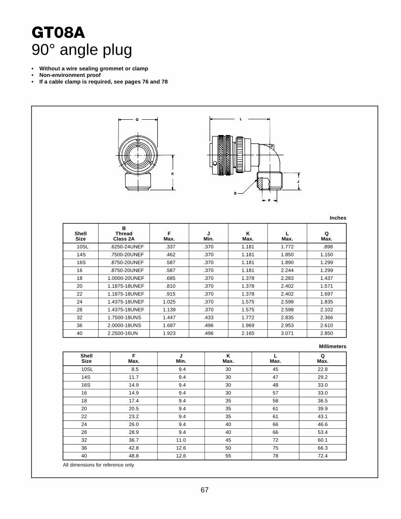
67
GT08A90° angle plug
All dimensions for reference only.
Inches
ShellSize
BThread
Class 2AF
Max.J
Min.K
Max.L
Max.Q
Max.
10SL .6250-24UNEF .337 .370 1.181 1.772 .898
14S .7500-20UNEF .462 .370 1.181 1.850 1.150
16S .8750-20UNEF .587 .370 1.181 1.890 1.299
16 .8750-20UNEF .587 .370 1.181 2.244 1.299
18 1.0000-20UNEF .685 .370 1.378 2.283 1.437
20 1.1875-18UNEF .810 .370 1.378 2.402 1.571
22 1.1875-18UNEF .915 .370 1.378 2.402 1.697
24 1.4375-18UNEF 1.025 .370 1.575 2.598 1.835
28 1.4375-18UNEF 1.139 .370 1.575 2.598 2.102
32 1.7500-18UNS 1.447 .433 1.772 2.835 2.366
36 2.0000-18UNS 1.687 .496 1.969 2.953 2.610
40 2.2500-16UN 1.923 .496 2.165 3.071 2.850
Millimeters
ShellSize
FMax.
JMin.
KMax.
LMax.
QMax.
10SL 8.5 9.4 30 45 22.8
14S 11.7 9.4 30 47 29.2
16S 14.9 9.4 30 48 33.0
16 14.9 9.4 30 57 33.0
18 17.4 9.4 35 58 36.5
20 20.5 9.4 35 61 39.9
22 23.2 9.4 35 61 43.1
24 26.0 9.4 40 66 46.6
28 28.9 9.4 40 66 53.4
32 36.7 11.0 45 72 60.1
36 42.8 12.6 50 75 66.3
40 48.8 12.6 55 78 72.4
• Without a wire sealing grommet or clamp• Non-environment proof• If a cable clamp is required, see pages 76 and 78
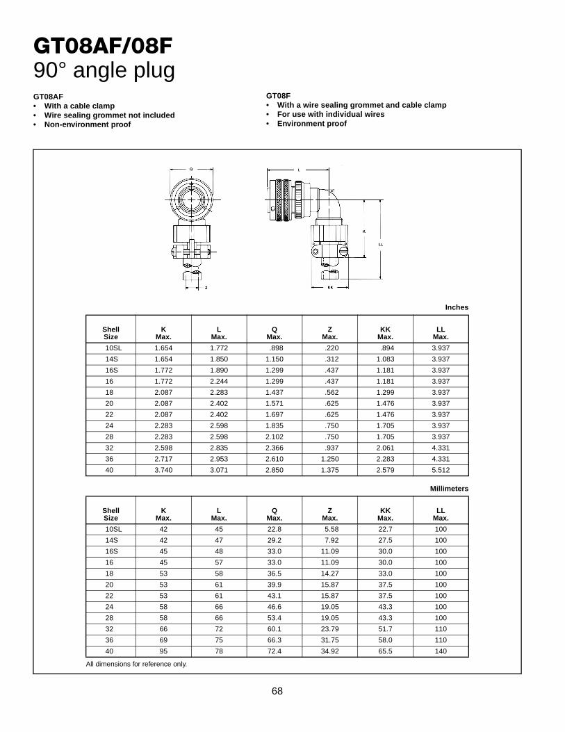
68
GT08AF/08F90° angle plug
GT08F• With a wire sealing grommet and cable clamp• For use with individual wires• Environment proof
GT08AF• With a cable clamp• Wire sealing grommet not included• Non-environment proof
All dimensions for reference only.
Inches
ShellSize
KMax.
LMax.
QMax.
ZMax.
KKMax.
LLMax.
10SL 1.654 1.772 .898 .220 .894 3.937
14S 1.654 1.850 1.150 .312 1.083 3.937
16S 1.772 1.890 1.299 .437 1.181 3.937
16 1.772 2.244 1.299 .437 1.181 3.937
18 2.087 2.283 1.437 .562 1.299 3.937
20 2.087 2.402 1.571 .625 1.476 3.937
22 2.087 2.402 1.697 .625 1.476 3.937
24 2.283 2.598 1.835 .750 1.705 3.937
28 2.283 2.598 2.102 .750 1.705 3.937
32 2.598 2.835 2.366 .937 2.061 4.331
36 2.717 2.953 2.610 1.250 2.283 4.331
40 3.740 3.071 2.850 1.375 2.579 5.512
Millimeters
ShellSize
KMax.
LMax.
QMax.
ZMax.
KKMax.
LLMax.
10SL 42 45 22.8 5.58 22.7 100
14S 42 47 29.2 7.92 27.5 100
16S 45 48 33.0 11.09 30.0 100
16 45 57 33.0 11.09 30.0 100
18 53 58 36.5 14.27 33.0 100
20 53 61 39.9 15.87 37.5 100
22 53 61 43.1 15.87 37.5 100
24 58 66 46.6 19.05 43.3 100
28 58 66 53.4 19.05 43.3 100
32 66 72 60.1 23.79 51.7 110
36 69 75 66.3 31.75 58.0 110
40 95 78 72.4 34.92 65.5 140
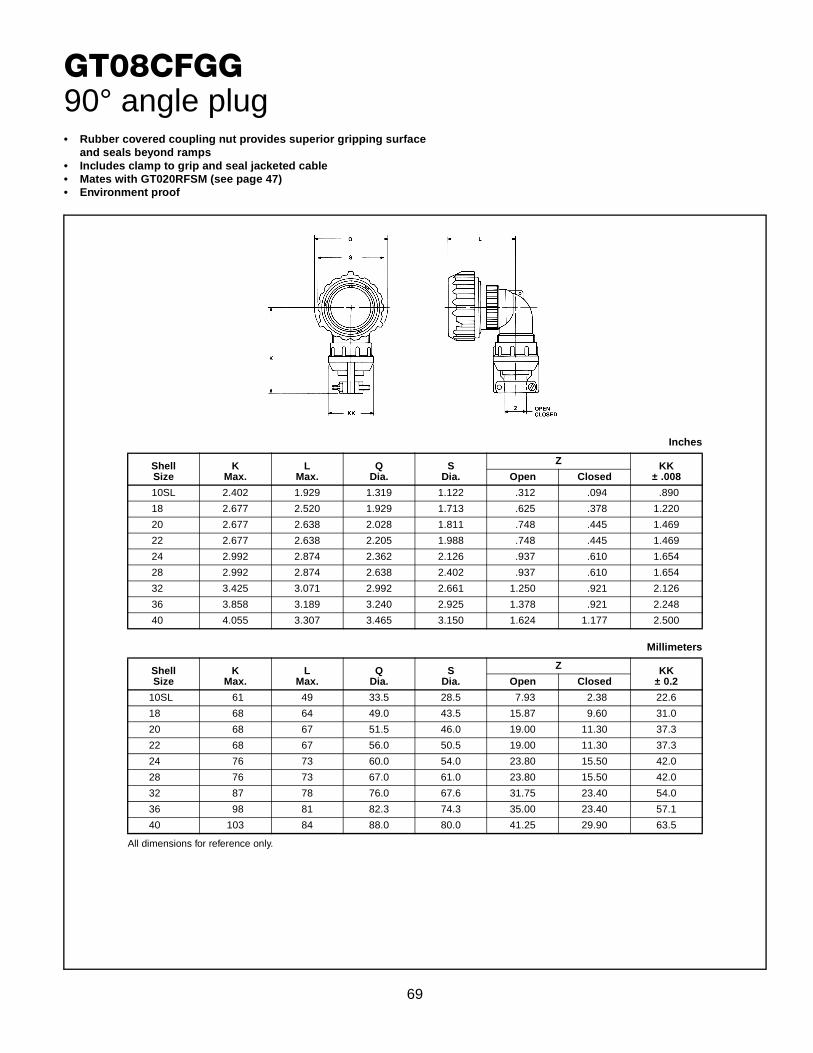
69
GT08CFGG90° angle plug• Rubber covered coupling nut provides superior gripping surface
and seals beyond ramps• Includes clamp to grip and seal jacketed cable• Mates with GT020RFSM (see page 47)• Environment proof
All dimensions for reference only.
Inches
ShellSize
KMax.
LMax.
QDia.
SDia.
Z KK± .008Open Closed
10SL 2.402 1.929 1.319 1.122 .312 .094 .890
18 2.677 2.520 1.929 1.713 .625 .378 1.220
20 2.677 2.638 2.028 1.811 .748 .445 1.469
22 2.677 2.638 2.205 1.988 .748 .445 1.469
24 2.992 2.874 2.362 2.126 .937 .610 1.654
28 2.992 2.874 2.638 2.402 .937 .610 1.654
32 3.425 3.071 2.992 2.661 1.250 .921 2.126
36 3.858 3.189 3.240 2.925 1.378 .921 2.248
40 4.055 3.307 3.465 3.150 1.624 1.177 2.500
Millimeters
ShellSize
KMax.
LMax.
QDia.
SDia.
Z KK± 0.2Open Closed
10SL 61 49 33.5 28.5 7.93 2.38 22.6
18 68 64 49.0 43.5 15.87 9.60 31.0
20 68 67 51.5 46.0 19.00 11.30 37.3
22 68 67 56.0 50.5 19.00 11.30 37.3
24 76 73 60.0 54.0 23.80 15.50 42.0
28 76 73 67.0 61.0 23.80 15.50 42.0
32 87 78 76.0 67.6 31.75 23.40 54.0
36 98 81 82.3 74.3 35.00 23.40 57.1
40 103 84 88.0 80.0 41.25 29.90 63.5

70
GT08R90° angle plug
All dimensions for reference only.
Inches
ShellSize
BThread
Class 2AF
Max.J
Min.K
Max.L
Max.Q
Max.
10SL .6250-24UNEF .337 .370 1.181 1.772 .898
14S .7500-20UNEF .462 .370 1.181 1.850 1.150
16S .8750-20UNEF .587 .370 1.181 1.890 1.299
16 .8750-20UNEF .587 .370 1.181 2.244 1.299
18 1.0000-20UNEF .685 .370 1.378 2.283 1.437
20 1.1875-18UNEF .810 .370 1.378 2.402 1.571
22 1.1875-18UNEF .915 .370 1.378 2.402 1.697
24 1.4375-18UNEF 1.025 .370 1.575 2.598 1.835
28 1.4375-18UNEF 1.139 .370 1.575 2.598 2.102
32 1.7500-18UNS 1.447 .433 1.772 2.835 2.366
36 2.0000-18UNS 1.687 .496 1.969 2.953 2.610
40 2.2500-16UN 1.923 .496 2.165 3.071 2.850
Millimeters
ShellSize
FMax.
JMin.
KMax.
LMax.
QMax.
10SL 8.5 9.4 30 45 22.8
14S 11.7 9.4 30 47 29.2
16S 14.9 9.4 30 48 33.0
16 14.9 9.4 30 57 33.0
18 17.4 9.4 35 58 36.5
20 20.5 9.4 35 61 39.9
22 23.2 9.4 35 61 43.1
24 26.0 9.4 40 66 46.6
28 28.9 9.4 40 66 53.4
32 36.7 11.0 45 72 60.1
36 42.8 12.6 50 75 66.3
40 48.8 12.6 55 78 72.4
• With a wire sealing grommet for conduit termination• For use with individual wires• Environment proof
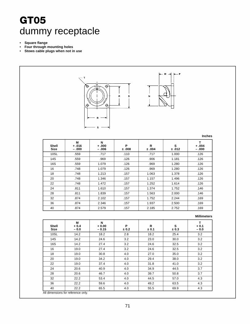
71
GT05dummy receptacle• Square flange• Four through mounting holes• Stows cable plugs when not in use
All dimensions for reference only.
Inches
ShellSize
M+ .016– .000
N+ .000– .006
P± .008
R± .004
S± .012
T+ .004– .000
10SL .559 .717 .110 .717 1.000 .126
14S .559 .969 .126 .906 1.181 .126
16S .559 1.079 .126 .969 1.280 .126
16 .748 1.079 .126 .969 1.280 .126
18 .748 1.213 .157 1.063 1.378 .126
20 .748 1.346 .157 1.157 1.496 .126
22 .748 1.472 .157 1.252 1.614 .126
24 .811 1.610 .157 1.374 1.752 .146
28 .811 1.839 .157 1.563 2.000 .146
32 .874 2.102 .157 1.752 2.244 .169
36 .874 2.346 .157 1.937 2.500 .169
40 .874 2.579 .157 2.185 2.752 .169
Millimeters
ShellSize
M+ 0.4– 0.0
N+ 0.00– 0.15
P± 0.2
R± 0.1
S± 0.3
T+ 0.1– 0.0
10SL 14.2 18.2 2.8 18.2 25.4 3.2
14S 14.2 24.6 3.2 23.0 30.0 3.2
16S 14.2 27.4 3.2 24.6 32.5 3.2
16 19.0 27.4 3.2 24.6 32.5 3.2
18 19.0 30.8 4.0 27.0 35.0 3.2
20 19.0 34.2 4.0 29.4 38.0 3.2
22 19.0 37.4 4.0 31.8 41.0 3.2
24 20.6 40.9 4.0 34.9 44.5 3.7
28 20.6 46.7 4.0 39.7 50.8 3.7
32 22.2 53.4 4.0 44.5 57.0 4.3
36 22.2 59.6 4.0 49.2 63.5 4.3
40 22.2 65.5 4.0 55.5 69.9 4.3

72
GTTBthru-bulkhead receptacles
All dimensions for reference only.
Inches
ShellSize
LMax.
M+ .016– .000
N+ .000– .006
P± .008
R± .004
S± .012
T+ .004– .000
10SL 1.488 .717 .717 .110 .717 1.000 .126
14S 1.488 .717 .969 .126 .906 1.181 .126
16S 1.488 .717 1.079 .126 .969 1.280 .126
16 2.049 .846 1.079 .126 .969 1.280 .126
18 2.049 .907 1.213 .157 1.063 1.378 .126
20 2.049 .907 1.346 .157 1.157 1.496 .126
22 2.049 .907 1.472 .157 1.252 1.614 .126
24 2.049 .907 1.610 .157 1.374 1.752 .146
28 2.049 .947 1.839 .157 1.563 2.000 .146
32 2.049 .947 2.102 .157 1.752 2.244 .169
36 2.049 .947 2.346 .157 1.937 2.500 .169
40 2.049 .947 2.579 .157 2.185 2.752 .169
Millimeters
ShellSize
LMax.
M+ 0.4– 0.0
N+ 0.00– 0.15
P± 0.2
R± 0.1
S± 0.3
T+ .004– .000
10SL 37.7 18.2 18.2 2.8 18.2 25.4 3.2
14S 37.7 18.2 24.6 3.2 23.0 30.0 3.2
16S 37.7 18.2 27.4 3.2 24.6 32.5 3.2
16 52.0 21.5 27.4 3.2 24.6 32.5 3.2
18 52.0 23.0 30.8 4.0 27.0 35.0 3.2
20 52.0 23.0 34.2 4.0 29.4 38.0 3.2
22 52.0 23.0 37.4 4.0 31.8 41.0 3.2
24 52.0 23.0 40.9 4.0 34.9 44.5 3.7
28 52.0 24.0 46.7 4.0 39.7 50.8 3.7
32 52.0 24.0 53.4 4.0 44.5 57.0 4.3
36 52.0 24.0 59.6 4.0 49.2 63.5 4.3
40 52.0 24.0 65.5 4.0 55.5 69.9 4.3
• Accepts mating plug on both sides• Four through mounting holes

73
GT Connectors – accessories10-40450, 10-36675, 10-580649 sealing gaskets
The Amphenol® plain flat gasket of synthetic rubber materialis provided to take complete advantage of waterproof andpressure sealing features. It is for use with the flangemounted receptacle.
This flat gasket is provided to give the maximum in connectorperformance. Its special feature is in providing the maximumradio shielding under difficult conditions of high receiver sen-sitivity and low signal strength while retaining the sealingcharacteristics of the plain gasket. This gasket is for use withthe flange mounting receptacle.
This gasket is provided for applications where the majorrequirement is resistance to the injurious effects of extremelylow temperature. Even at temperatures as low as –67°F thisgasket retains its resiliency and will seal a pressure differen-tial of 30 psi.
The rear panel gasket is equivalent to the plain flat gasketmade of synthetic rubber material, and is used for back panelmounting.
Inches
Installation Dimensions
MSShellSize
A± .010
Front Panel Versions
B+ .016– .000
Rear Panel Version
B+ .016– .000
C+ .016– .000
D± .010
10SL .719 .625 .724 1.000 .172
14S .906 .875 .976 1.188 .172
16S .969 1.000 1.087 1.281 .172
16 .969 1.000 1.087 1.281 .172
18 1.063 1.125 1.220 1.375 .203
20 1.156 1.250 1.354 1.500 .203
22 1.250 1.375 1.480 1.625 .203
24 1.375 1.500 1.618 1.750 .203
28 1.563 1.750 1.846 2.000 .203
32 1.750 2.000 2.110 2.250 .219
36 1.938 2.188 2.354 2.500 .219
40 2.188 2.438 2.587 2.750 .219
Millimeters
Installation Dimensions
MSShellSize
A± 0.2
Front Panel Versions
B+ 0.4– 0.0
Rear Panel Version
B+ 0.4– 0.0
C+ 0.4– 0.0
D± 0.2
10SL 18.2 15.9 18.4 25.4 4.36
14S 23.0 22.2 24.8 30.2 4.36
16S 24.6 25.4 27.6 32.5 4.36
16 24.6 25.4 27.6 32.5 4.36
18 27.0 28.57 31.0 35.0 5.15
20 29.4 31.75 34.4 38.1 5.15
22 31.8 34.9 37.6 41.2 5.15
24 34.9 38.1 41.1 44.5 5.15
28 39.7 44.45 46.9 50.8 5.15
32 44.5 50.8 53.6 57.2 5.56
36 49.2 55.57 59.8 63.5 5.56
40 55.6 61.92 65.7 69.9 5.56
Order Data
Front Panel Plain Version
Front PanelShielding Version
Front PanelLow Temperature
Version
Rear PanelVersion
10-40450-10 10-40450-10S 10-36675-10 10-580649-10
10-40450-14 10-40450-14S 10-36675-14 10-580649-14
10-40450-16 10-40450-16S 10-36675-16 10-580649-16
10-40450-16 10-40450-16S 10-36675-16 10-580649-16
10-40450-18 10-40450-18S 10-36675-18 10-580649-18
10-40450-20 10-40450-20S 10-36675-20 10-580649-20
10-40450-22 10-40450-22S 10-36675-22 10-580649-22
10-40450-24 10-40450-24S 10-36675-24 10-580649-24
10-40450-28 10-40450-28S 10-36675-28 10-580649-26
10-40450-32 10-40450-32S 10-36675-32 10-580649-32
10-40450-36 10-40450-36S 10-36675-36 10-580649-36
10-40450-40 10-40450-40S 10-36675-40 10-580649-40

74
GT Connectors – accessoriesreceptacle protection caps
* To complete order number, add shell size and suffix number. For example, shell size 11 with olive drab cadmium plate would be10-580902-113.
All dimensions for reference only.
Inches
ShellSize
D+ .020– .000
LMax.
NMax.
LLApprox.
11 .173 .650 .905 5.000
14 .173 .650 1.181 5.000
16 .173 .827 1.280 5.000
17 .173 .650 1.280 5.000
18 .173 .827 1.457 5.000
20 .173 .827 1.594 5.000
22 .173 .827 1.713 5.000
24 .173 .827 1.850 5.000
28 .220 .827 2.126 7.480
32 .220 .827 2.382 7.480
36 .220 .827 2.638 6.890
40 .220 .827 2.874 7.480
Millimeters
ShellSize
D+ 0.5– 0.0
LMax.
NMax.
LLApprox.
11 4.4 16.5 23.0 127
14 4.4 16.5 30.0 127
16 4.4 21.0 32.5 127
17 4.4 16.5 32.5 127
18 4.4 21.0 37.0 127
20 4.4 21.0 40.5 127
22 4.4 21.0 43.5 127
24 4.4 21.0 47.0 127
28 5.6 21.0 54.0 190
32 5.6 21.0 60.5 190
36 5.6 21.0 67.0 175
40 5.6 21.0 73.0 190
Finish Suffix
Black anodize -XX2
Olive drab cadmium plate -XX3
Olive drab cadmium nickel base -XX9
• Protective metal caps which seal the front of receptacles• Includes a chain for retention of the cap at the required
location• For receptacles: GT00, 01, 02, 020, 030, 070
* 10-580902-XXX

75
GT Connectors – accessoriesplug protection caps• Protective metal caps which seal the front of plugs• Includes a chain for retention of the cap at the required
location• For receptacles: GT06, 08
* To complete order number, add shell size and suffix number. For example, shell size 11 with olive drab cadmium plate would be10-580903-113.
All dimensions for reference only.
Inches
ShellSize
D+ .020– .000
LMax.
NMax.
LLApprox.
11 .157 .945 .807 5.000
14 .157 .945 1.059 5.000
16 .157 .945 1.169 5.000
17 .157 .945 1.169 5.000
18 .157 .945 1.303 5.000
20 .189 1.260 1.437 5.520
22 .189 1.260 1.563 5.520
24 .189 1.260 1.701 5.520
28 .189 1.260 1.929 7.480
32 .220 1.260 2.193 7.480
36 .220 1.260 2.437 7.480
40 .220 1.260 2.665 7.480
Millimeters
ShellSize
D+ 0.5– 0.0
LMax.
NMax.
LLApprox.
11 4.0 24 20.5 127
14 4.0 24 26.9 127
16 4.0 24 29.7 127
17 4.0 24 29.7 127
18 4.0 24 33.1 127
20 4.8 32 36.5 140
22 4.8 32 39.7 140
24 4.8 32 43.2 140
28 4.8 32 49.0 190
32 5.6 32 55.7 190
36 5.6 32 61.9 190
40 5.6 32 67.7 190
Finish Suffix
Black anodize -XX2
Olive drab cadmium plate -XX3
Olive drab cadmium nickel base -XX9
* 10-580903-XXX

76
GT Connectors – accessoriesM85049/41 (MS3057-A) cable clamp
All dimensions for reference only.
Inches
PartNumber
Used withShell Size
Used withBushing B D G F
VThread
Class 2B
M85049/41-4A 10SL MS3420-4 .315 .395 .812 .866 .6250-24 UNEF
M85049/41-6A 14S MS3420-6 .442 .395 .875 1.063 .7500-20 UNEF
M85049/41-8A 16 - 16S MS3420-8 .568 .395 .945 1.145 .8750-20 UNEF
M85049/41-10A 18 MS3420-10 .633 .395 .945 1.244 1.0000-20 UNEF
M85049/41-12A 20 - 22 MS3420-12 .758 .395 .945 1.475 1.1875-18 UNEF
M85049/41-16A 24 - 28 MS3420-16 .948 .395 1.031 1.700 1.4375-18 UNEF
M85049/41-20A 32 MS3420-20 1.256 .460 1.094 2.055 1.7500-18 UNS
M85049/41-24A 36 MS3420-24 1.380 .520 1.157 2.265 2.0000-18 UNS
M85049/41-28A 40 MS3420-28 1.625 .520 1.685 2.683 2.2500-16 UN
Millimeters
PartNumber
Used withShell Size
Used withBushing B D G F
M85049/41-4A 10SL MS3420-4 8.0 10.0 20.6 22
M85049/41-6A 14S MS3420-6 11.0 10.0 22.2 27
M85049/41-8A 16 - 16S MS3420-8 14.4 10.0 24.0 29
M85049/41-10A 18 MS3420-10 16.1 10.0 24.0 32
M85049/41-12A 20 - 22 MS3420-12 19.2 10.0 24.0 37
M85049/41-16A 24 - 28 MS3420-16 24.1 10.0 26.2 43
M85049/41-20A 32 MS3420-20 31.9 11.7 27.8 52
M85049/41-24A 36 MS3420-24 35.0 13.2 29.4 58
M85049/41-28A 40 MS3420-28 41.3 13.2 42.8 68
• Concentric cable clamps, insure strain relief and centrallocation of the cable
• Can be used with bushing MS3420

77
GT Connectors – accessoriesMS3420 bushing
All dimensions for reference only.
Inches
PartNumber
Used withCable Clamp A B C D
MS3420-3 M85049/41-3A .130 .210 .379 2.875
MS3420-4 M85049/41-4A .220 .302 .505 2.750
MS3420-6 M85049/41-6A .312 .427 .619 2.625
MS3420-8 M85049/41-8A .437 .552 .744 2.500
MS3420-10 M85049/41-10A .562 .615 .889 2.375
MS3420-12 M85049/41-12A .625 .740 1.084 2.250
MS3420-16 M85049/41-16A .750 .927 1.314 2.125
MS3420-20 M85049/41-20A .937 1.240 1.598 2.000
MS3420-24 M85049/41-24A 1.250 1.365 1.847 1.875
MS3420-28 M85049/41-28A 1.375 1.614 2.085 1.750
Millimeters
PartNumber
Used withCable Clamp A B C D
MS3420-3 M85049/41-3A 3.30 5.3 9.60 73.0
MS3420-4 M85049/41-4A 5.58 7.7 12.80 69.8
MS3420-6 M85049/41-6A 7.92 10.8 15.70 66.8
MS3420-8 M85049/41-8A 11.09 14.0 18.90 63.5
MS3420-10 M85049/41-10A 14.27 15.6 22.58 60.3
MS3420-12 M85049/41-12A 15.87 18.8 27.50 57.1
MS3420-16 M85049/41-16A 19.05 23.5 33.40 53.9
MS3420-20 M85049/41-20A 23.79 31.5 40.60 50.8
MS3420-24 M85049/41-24A 31.75 34.7 46.90 47.6
MS3420-28 M85049/41-28A 34.92 41.0 52.90 44.4
• Bushing of synthetic rubber to be used with cable clamps for protection of the cable or wires
• Can be telescoped for smaller cable diameters
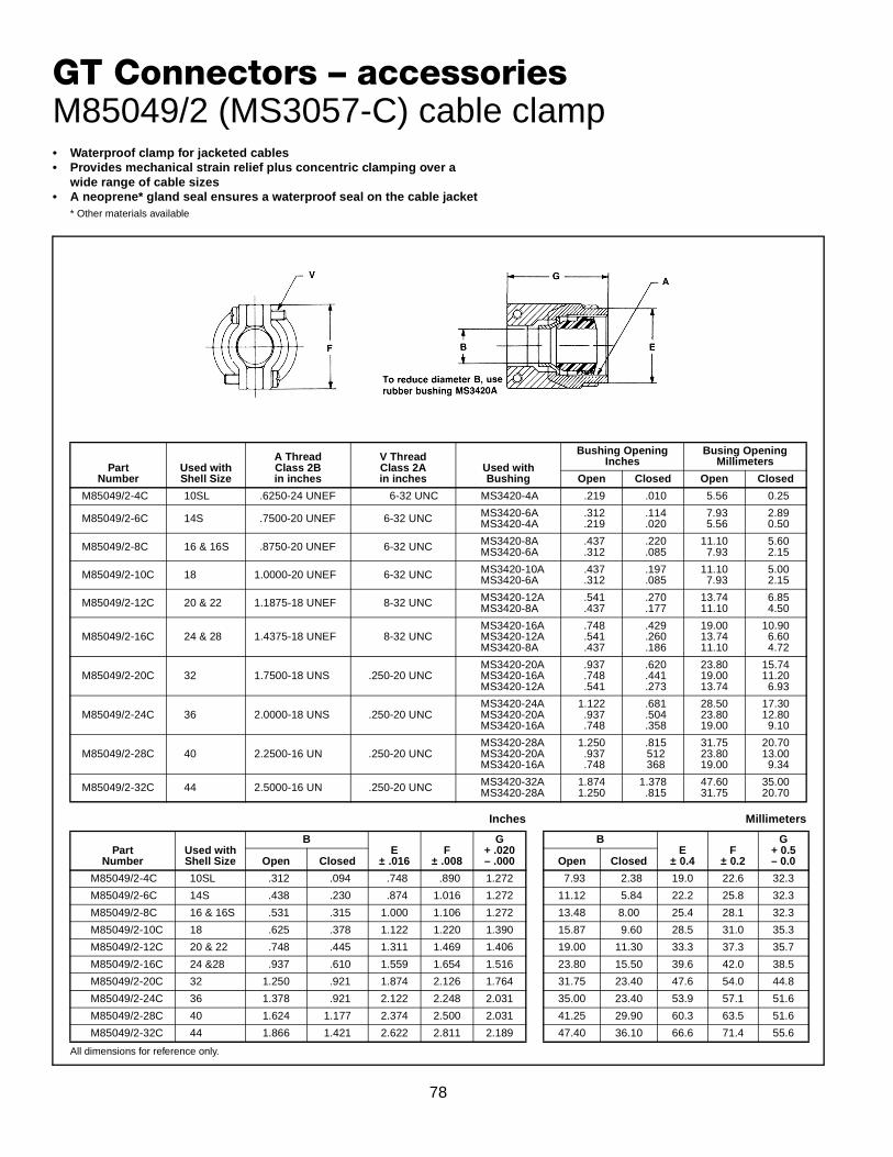
78
GT Connectors – accessoriesM85049/2 (MS3057-C) cable clamp
PartNumber
Used withShell Size
A ThreadClass 2Bin inches
V ThreadClass 2Ain inches
Used with Bushing
Bushing OpeningInches
Busing OpeningMillimeters
Open Closed Open Closed
M85049/2-4C 10SL .6250-24 UNEF 6-32 UNC MS3420-4A .219 .010 5.56 0.25
M85049/2-6C 14S .7500-20 UNEF 6-32 UNC MS3420-6AMS3420-4A
.312
.219.114.020
7.935.56
2.890.50
M85049/2-8C 16 & 16S .8750-20 UNEF 6-32 UNC MS3420-8AMS3420-6A
.437
.312.220.085
11.107.93
5.602.15
M85049/2-10C 18 1.0000-20 UNEF 6-32 UNC MS3420-10AMS3420-6A
.437
.312.197.085
11.107.93
5.002.15
M85049/2-12C 20 & 22 1.1875-18 UNEF 8-32 UNC MS3420-12AMS3420-8A
.541
.437.270.177
13.7411.10
6.854.50
M85049/2-16C 24 & 28 1.4375-18 UNEF 8-32 UNCMS3420-16AMS3420-12AMS3420-8A
.748
.541
.437
.429
.260
.186
19.0013.7411.10
10.906.604.72
M85049/2-20C 32 1.7500-18 UNS .250-20 UNCMS3420-20AMS3420-16AMS3420-12A
.937
.748
.541
.620
.441
.273
23.8019.0013.74
15.7411.206.93
M85049/2-24C 36 2.0000-18 UNS .250-20 UNCMS3420-24AMS3420-20AMS3420-16A
1.122.937.748
.681
.504
.358
28.5023.8019.00
17.3012.809.10
M85049/2-28C 40 2.2500-16 UN .250-20 UNCMS3420-28AMS3420-20AMS3420-16A
1.250.937.748
.815512368
31.7523.8019.00
20.7013.009.34
M85049/2-32C 44 2.5000-16 UN .250-20 UNC MS3420-32AMS3420-28A
1.8741.250
1.378.815
47.6031.75
35.0020.70
All dimensions for reference only.
Inches
PartNumber
Used withShell Size
BE
± .016F
± .008
G+ .020– .000Open Closed
M85049/2-4C 10SL .312 .094 .748 .890 1.272
M85049/2-6C 14S .438 .230 .874 1.016 1.272
M85049/2-8C 16 & 16S .531 .315 1.000 1.106 1.272
M85049/2-10C 18 .625 .378 1.122 1.220 1.390
M85049/2-12C 20 & 22 .748 .445 1.311 1.469 1.406
M85049/2-16C 24 &28 .937 .610 1.559 1.654 1.516
M85049/2-20C 32 1.250 .921 1.874 2.126 1.764
M85049/2-24C 36 1.378 .921 2.122 2.248 2.031
M85049/2-28C 40 1.624 1.177 2.374 2.500 2.031
M85049/2-32C 44 1.866 1.421 2.622 2.811 2.189
Millimeters
BE
± 0.4F
± 0.2
G+ 0.5– 0.0Open Closed
7.93 2.38 19.0 22.6 32.3
11.12 5.84 22.2 25.8 32.3
13.48 8.00 25.4 28.1 32.3
15.87 9.60 28.5 31.0 35.3
19.00 11.30 33.3 37.3 35.7
23.80 15.50 39.6 42.0 38.5
31.75 23.40 47.6 54.0 44.8
35.00 23.40 53.9 57.1 51.6
41.25 29.90 60.3 63.5 51.6
47.40 36.10 66.6 71.4 55.6
• Waterproof clamp for jacketed cables• Provides mechanical strain relief plus concentric clamping over a
wide range of cable sizes• A neoprene* gland seal ensures a waterproof seal on the cable jacket
* Other materials available

79
GT – accessoriesrear mounting data – receptacles, 10-405996sealing plugs, sealing ranges, backshell torque forces
REAR MOUNTING DATAMAXIMUM PANEL THICKNESS
Size
Dimension D
GT00/020 GT030
Inches (mm) Inches (mm)
10SL .146 3.70 .303 7.70
14S .146 3.70 .303 7.70
16S .146 3.70 .303 7.70
16 .145 3.70 .242 6.15
18 .145 3.70 .303 7.70
20 .145 3.70 .303 7.70
22 .145 3.70 .303 7.70
24 .207 5.25 .303 7.70
28 .207 5.25 .343 8.70
32 .241 6.10 .309 7.85
36 .241 6.10 .309 7.85
40 .237 6.02 .309 7.85
SEALING PLUG 10-405996-XX
Sealing plugs are used to fill unused holes in multi-holedgrommet configurations.
All dimensions for reference only.
GROMMET HOLESEALING RANGES
Hole Size
Sealing Range
(mm) Inches
16 2.3 – 3.0 .090 – .118
12 3.2 – 4.5 .126 – .177
8 3.8 – 6.5 .150 – .256
4 7.1 – 9.3 .279 – .366
0 10.0 – 13.7 .394 – .539
RECOMMENDED TORQUE FORCESCONNECTOR BACKSHELLS
SizeIn./Lb.Max.
10SL 26
14S 44
16 50
16S 50
18 55
20 65
22 85
24 90
28 114
32 120
36 153
40 170
Order No.Contact
SizeWireSize
Color Code
Inches
A Dia.±.010
B±.005
C±.010
10-405996-16 16 20-16 Blue .083 .133 .564**
10-405996-12 12 14-12 Yellow .121 .171 .564**
10-405996-8 8 10-8 White .185 .315 .470
10-405996-4 4 4-6 Blue .310 .415 .470
10-405996-0 0 0-2 Yellow .440 .605 1.000
** ± .020 (in.) *** ± 0.5 (mm)
Millimeters
A Dia.± 0.2
B± 0.1
C± 0.2
2.1 3.4 14.3***
3.1 4.3 14.3***
4.7 8.0 11.9
7.9 10.5 11.9
11.2 15.4 25.4

80
Machined copper alloy contacts in a full range of sizes, with closed entry socket design in thesize 12 and 16 contacts. A heavy silver-plated finish is deposited on all MS style solder con-tacts for maximum corrosion resistance, maximum current carrying capacity and low millivoltdrop. Gold plated contacts are also available. (See how to order, pg. 83).
SOLDER CONTACTS*
PartNumber
Pin/Socket
Mating EndSize
Wire BarrelSize
AllowableWire Size
Test Current**Amps
10-40569
10-597107-16( ) or10-40568
Pin
Socket16 Short 16
16182022
13107.55
10-40599
10-597107-17( ) or10-40598
Pin
Socket16 Long 16
16182022
13107.55
10-33646
10-597107-13( ) or10-33644
Pin
Socket12 12 12
142317
10-35531
10-35532
Pin
Socket8 8 8
104633
10-35529
10-35530
Pin
Socket4 4
46
8060
10-35527
10-35528
Pin
Socket0 0
012
150125100
* Solder Wells Filled
** Contact ratings as stated are test ratings only. The connector may not withstand full rated current through all contacts continuously. Please note that the electrical data given is not an establishment of electrical safety factors. This is left entirely in the designer’s hands as he can best determine which peak voltage, switching surges, transients, etc. can be expected in a particular circuit.
Table ICONTACT ARRANGEMENT
SERVICE RATING
MSService Rating
RecommendedOperating Voltage*
at Sea Level
Effective Creepage Distance
Nom.
Mechanical Spacing
Nom.DC AC (RMS)
Inst. 250 200 1/16
A 700 500 1/8 1/16
D 1250 900 3/16 1/8
E 1750 1250 1/4 3/16
B 2450 1750 5/16 1/4
C 4200 3000 1 5/16
* The values listed in Table I represent operating val-ues which include a generous safety factor. It maybe necessary for some applications to exceed theoperating voltages listed here. If this is necessary,designers will find Table II useful for determining thedegree to which the recommended values of Table Ican be exceeded.
† Not corrected for changes in density due to variations in temperature
** No attempt has been made to recommend operating voltages. The designer must determine his own oper-ating voltage by the application of a safety factor to the above derating chart to compensate for circuit tran-sients, surges, etc.
Table IIALTITUDE VOLTAGEDERATING** CHART
MSService Rating
NominalDistance
Standard SeaLevel Conditions
Pressure Altitude †50,000 Feet
Pressure Altitude †70,000 Feet
Airspace Creepage
Minimum Flashover
VoltageAC (RMS)
TestVoltage
AC (RMS)
Minimum Flashover
VoltageAC (RMS)
TestVoltage
AC (RMS)
Minimum Flashover
VoltageAC (RMS)
TestVoltage
AC (RMS)
Inst. 1/32 1/16 1400 1000 550 400 325 260
A 1/16 1/8 2800 2000 800 600 450 360
D 1/8 3/16 3600 2800 900 675 500 400
E 3/16 1/4 4500 3500 1000 750 550 440
B 1/4 5/16 5700 4500 1100 825 600 480
C 5/16 1 8500 7000 1300 975 700 560
GT Connectorssolder contacts

81
Machined from copper alloys and silver-plated for maximum corrosion resistance, with a minimum milli-volt drop and a maximum current carrying capacity, the size 16 and 12 socket contacts are of the closedentry design. Crimp contacts are available for all MS insert arrangements and are identified with anAmphenol® proprietary number. Gold plated contacts are also available. (See how to order, pg. 83).
CRIMP CONTACTS*
PartNumber
Pin/Socket
Mating EndSize
Wire BarrelSize
AllowableWire Size
Required Wire Adapter Sleeve
Test Current**Amps
10-40553
10-597109-161 or10-40552
Pin
Socket16 Short 16
16182022*
–––
10-74696-6
13107.55
10-40557
10-597109-171 or10-40556
Pin
Socket16 Long 16
16182022*
–––
10-74696-6
13107.55
10-40561
10-597109-131 or10-40560
Pin
Socket12 12 12
14––
2317
10-40792
10-40793
Pin
Socket8 8 8
10*–
10-74696-14633
10-40564
10-40565
Pin
Socket4 4
46*
–10-74696-2
8060
10-581806
10-581808
Pin
Socket0 0
02*
–10-74696-7
150125
* When using wire adapter sleeve shown
** Contact ratings as stated are test ratings only. The connector may not withstand full rated current through all contacts continuously. Please note that the electrical data given is not an establishment of electrical safety factors. This is left entirely in the designer’s hands as he can best determine which peak voltage, switching surges, transients, etc. can be expected in a particular circuit.
Additional contact variations are available; consult Amphenol, Sidney, NY for information.
Table ICONTACT ARRANGEMENT
SERVICE RATING
MSService Rating
RecommendedOperating Voltage*
at Sea Level
Effective Creepage Distance
Nom.
Mechanical Spacing
Nom.DC AC (RMS)
Inst. 250 200 1/16
A 700 500 1/8 1/16
D 1250 900 3/16 1/8
E 1750 1250 1/4 3/16
B 2450 1750 5/16 1/4
C 4200 3000 1 5/16
* The values listed in Table I represent operating val-ues which include a generous safety factor. It maybe necessary for some applications to exceed theoperating voltages listed here. If this is necessary,designers will find Table II useful for determining thedegree to which the recommended values of Table Ican be exceeded.
† Not corrected for changes in density due to variations in temperature
** No attempt has been made to recommend operating voltages. The designer must determine his own oper-ating voltage by the application of a safety factor to the above derating chart to compensate for circuit tran-sients, surges, etc.
Table IIALTITUDE VOLTAGEDERATING** CHART
MSService Rating
NominalDistance
Standard SeaLevel Conditions
Pressure Altitude †50,000 Feet
Pressure Altitude †70,000 Feet
Airspace Creepage
Minimum Flashover
VoltageAC (RMS)
TestVoltage
AC (RMS)
Minimum Flashover
VoltageAC (RMS)
TestVoltage
AC (RMS)
Minimum Flashover
VoltageAC (RMS)
TestVoltage
AC (RMS)
Inst. 1/32 1/16 1400 1000 550 400 325 260
A 1/16 1/8 2800 2000 800 600 450 360
D 1/8 3/16 3600 2800 900 675 500 400
E 3/16 1/4 4500 3500 1000 750 550 440
B 1/4 5/16 5700 4500 1100 825 600 480
C 5/16 1 8500 7000 1300 975 700 560
GT Connectorscrimp contacts
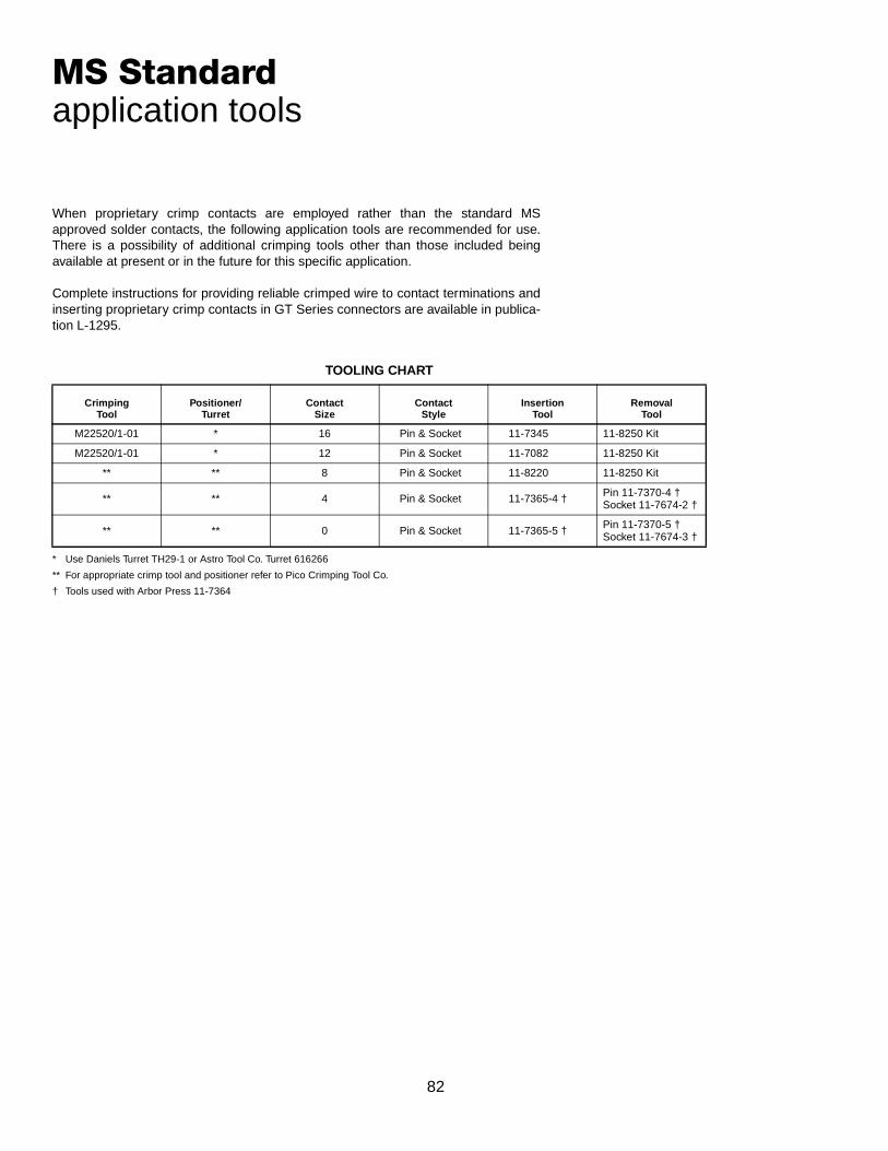
82
When proprietary crimp contacts are employed rather than the standard MSapproved solder contacts, the following application tools are recommended for use.There is a possibility of additional crimping tools other than those included beingavailable at present or in the future for this specific application.
Complete instructions for providing reliable crimped wire to contact terminations andinserting proprietary crimp contacts in GT Series connectors are available in publica-tion L-1295.
* Use Daniels Turret TH29-1 or Astro Tool Co. Turret 616266
** For appropriate crimp tool and positioner refer to Pico Crimping Tool Co.
† Tools used with Arbor Press 11-7364
TOOLING CHART
CrimpingTool
Positioner/Turret
ContactSize
ContactStyle
InsertionTool
RemovalTool
M22520/1-01 * 16 Pin & Socket 11-7345 11-8250 Kit
M22520/1-01 * 12 Pin & Socket 11-7082 11-8250 Kit
** ** 8 Pin & Socket 11-8220 11-8250 Kit
** ** 4 Pin & Socket 11-7365-4 † Pin 11-7370-4 †Socket 11-7674-2 †
** ** 0 Pin & Socket 11-7365-5 †Pin 11-7370-5 †Socket 11-7674-3 †
MS Standardapplication tools

83
Amphenol GT Connectorshow to order, connector intermateability
Part Number SystemGT C 00 A 36-5 P W (002)
1 2 3 4 5 6 7
1. Contact Style and Insert MaterialC = CrimpS = SolderCY = Crimp with VitonSY = Solder with VitonCL = Crimp with low smoke/flame retardant insertsSL = Solder with low smoke/flame retardant insertsNo designation required for Neoprene components
2. Shell Style00 - Wall mount receptacle01 - Inline receptacle02 - Box mount receptacle020 - Box mount receptacle with accessory threads030 - Square flange receptacle - rear panel mount05 - Dummy receptacle06 - Straight plug062 - Straight plug with deep serrated coupling nut*064 - Panel mounted plug with heavy duty coupling nut065 - Straight plug with long heavy duty coupling nut07 - Jam nut receptacle - rear panel mount070 - Jam nut receptacle with accessory threads08 - 90° angle plugTB - Thru-bulkhead
3. Connector ClassSee pages 32–72
4. Shell Size and ArrangementSee pages 2–4For thermocouple arrangements, see pages 27–31
5. Contact StyleP designates pin contactsS designates socket contacts
6. Alternate PositionW, X, Y and Z - See page 5.No suffix required for normal position.
7. Connector Modification*Omit for standard olive drab with silver plated contactsi.e.: (G96) Black anodize
(014) Olive drab cadmium plate, nickel base(A24) gold/nickel plated contacts(025) Black zinc cobalt(027) Conductive black zinc cobalt(024) Green zinc cobalt
* Consult Amphenol, Sidney, NY
MATEABILITY WITHIDENTICAL CONTACT ARRANGEMENTS
Connector Style Mateable with Style
GT00 GT06 / 062 / 064 / 065 / 08
GT01 GT06 / 062 / 064 / 065 / 08
GT02 GT06 / 062 / 064 / 065 / 08
GT020 GT06 / 062 / 064 / 065 / 08
GT030 GT06 / 062 / 064 / 065 / 08
GT06 / 062 / 064 / 065 GT00 / 01 / 02 / 020 / 03 / 030 / 05 / 070 / TB
GT07 / 070 GT06 / 062 / 064 / 065 / 08
GT08 GT00 / 01 / 02 / 020 / 03 / 030 / 05 / 070 / TB
GTTB GT06 / 062 / 064 / 065 / 08
®

84
Special ApplicationGT Connectors
GT-PC Connectors for High Voltage Power Appli-cations
The Amphenol® GT-PC connectors were developed for use inthe High Voltage Power Distribution industry. Incorporating allthe standard features of the popular GT series, these con-nectors will prevent accidental electrical shocks to the techni-cians. “Dead Front” pin contacts in size 0 are recessed into asocket insert, preventing inadvertent contact with a live cir-cuit. The GT-PC series has been UL approved.
“First Mate - Last Break” features on one or more of the pinsprovide an additional measure of operator safety.
Termination to the conductors is accomplished with an Allenwrench or the traditional crimp or solder method. If Allenwrench is used, torque allen screws 40-50 in. lbs.
Other features of the GT-PC connector include:• Quick positive coupling; audible, tactile and visual mating
indicators• Full range of shell styles available• Waterproof• No lockwiring required• Wide selection of backshells and adapters available• Numerous conductive and non-conductive plating options• Heavy duty, rubber over-molded coupling nut increases
gripping surface and prevents damage to the connector insevere environments
• Up to 100 amps per contact, continuous current carryingcapability
• Available in insert patterns:22-7, 36-4, 36-5, 40-5, 40-57 Consult Amphenol Aerospace for availability of other pat-terns.
For further information on Amphenol® GT-PC connectors,request Product Data Sheet #173 from your local Amphenolsales office or Amphenol, Sidney, NY.
GT Connectors for the HMI Lighting Industry
Amphenol provides the GT connector for the HMI lighting industry. These connectorsare designed for the rugged use experienced during stage shows and other entertain-ment events, even outside in the elements. The same GT feature of a three point bayo-net coupling system which gives visual and tactile indication of full mating, and thesame ruggedness to survive 2000 mating cycles are provided.
Unique features of this connector series include color-coded receptacle shells withmatching backshells on the cable plugs. The colors can be matched to specific wattagecables and/or light systems. A wide selection of environment adapters designed to sealon the outside diameter of specific cable diameters can be fitted to the backshells.
Applications for these connectors include power and control of lighting trusses, andportable power and dimmer racks.
For more information on Amphenol® GT connectors for the HMI lighting industryrequest Product Data Sheet #174 from your local sales office or Amphenol, Sidney, NY
Amphenol ® GT-PC Connectors with Featuresthat Provide Increased Operator Safety