amphenol gt series reverse bayonet coupling connectors · amphenol gt series reverse bayonet...
TRANSCRIPT

Amphenol GT SeriesReverse Bayonet Coupling Connectors
Amphenol
12-024-8
®
Ruggedized Connector Seriesfor Rail/Mass Transit and otherHarsh Environments
AMPHENOL CORPORATIONAmphenol Industrial Operations
40-60 Delaware AvenueSidney, New York 13838-1395Phone: 800-678-0141 or 607-563-5011www.amphenol-industrial.com

Table of Contents Page No.Amphenol® GT Series Reversed Bayonet Coupling ConnectorsGeneral Description - - - - - - - - - - - - - - - - - - - - - - - - - - - - - - - - - - - - - - - - - - - - - - - - - - - - - - - - - - - - - - - - - - - 1GT Series insert availability charts - - - - - - - - - - - - - - - - - - - - - - - - - - - - - - - - - - - - - - - - - - - - - - - - - - - - - - - 2-4GT Series insert alternate positioning - - - - - - - - - - - - - - - - - - - - - - - - - - - - - - - - - - - - - - - - - - - - - - - - - - - - - - - 5GT Series contact arrangements - - - - - - - - - - - - - - - - - - - - - - - - - - - - - - - - - - - - - - - - - - - - - - - - - - - - - - - 6-28GT Connector Classes - - - - - - - - - - - - - - - - - - - - - - - - - - - - - - - - - - - - - - - - - - - - - - - - - - - - - - - - - - - - - - - - 29
GT00A wall mount receptacle for front panel mounting - - - - - - - - - - - - - - - - - - - - - - - - - - - - - - - - - - - - - 30GT00AF/00F wall mount receptacle for front panel mounting - - - - - - - - - - - - - - - - - - - - - - - - - - - - - - - - - 31GT00CF/00CFZ wall mount receptacle for front panel mounting - - - - - - - - - - - - - - - - - - - - - - - - - - - - - - - 32GT00G wall mount receptacle for front panel mounting - - - - - - - - - - - - - - - - - - - - - - - - - - - - - - - - - - - - - 33GT00LCF/00LCFZ wall mount receptacle for front panel mounting - - - - - - - - - - - - - - - - - - - - - - - - - - - - - 34GT00R wall mount receptacle for front panel mounting - - - - - - - - - - - - - - - - - - - - - - - - - - - - - - - - - - - - - 35GT00RV wall mount receptacle for front panel mounting - - - - - - - - - - - - - - - - - - - - - - - - - - - - - - - - - - - - 36GT01A inline receptacle - - - - - - - - - - - - - - - - - - - - - - - - - - - - - - - - - - - - - - - - - - - - - - - - - - - - - - - - - - - 37GT01AF/01F inline receptacle- - - - - - - - - - - - - - - - - - - - - - - - - - - - - - - - - - - - - - - - - - - - - - - - - - - - - - - 38GT01G inline receptacle - - - - - - - - - - - - - - - - - - - - - - - - - - - - - - - - - - - - - - - - - - - - - - - - - - - - - - - - - - - 39GT01LCF/01LCFZ inline receptacle - - - - - - - - - - - - - - - - - - - - - - - - - - - - - - - - - - - - - - - - - - - - - - - - - - 40GT01R inline receptacle - - - - - - - - - - - - - - - - - - - - - - - - - - - - - - - - - - - - - - - - - - - - - - - - - - - - - - - - - - - 41GT01RV inline receptacle - - - - - - - - - - - - - - - - - - - - - - - - - - - - - - - - - - - - - - - - - - - - - - - - - - - - - - - - - - 42GT02R/02RFS box mount receptacle for front panel mounting - - - - - - - - - - - - - - - - - - - - - - - - - - - - - - - - 43GT020R/020RFSM box mount receptacle for front panel mounting- - - - - - - - - - - - - - - - - - - - - - - - - - - - - 44GT030 square flange receptacle for rear panel mounting- - - - - - - - - - - - - - - - - - - - - - - - - - - - - - - - - - - - 45GT030A square flange receptacle for rear panel mounting- - - - - - - - - - - - - - - - - - - - - - - - - - - - - - - - - - - 46GT030AF/030F square flange receptacle for rear panel mounting - - - - - - - - - - - - - - - - - - - - - - - - - - - - - 47GT030G square flange receptacle for rear panel mounting - - - - - - - - - - - - - - - - - - - - - - - - - - - - - - - - - - 48GT030LCF/030LCFZ square flange receptacle for rear panel mounting - - - - - - - - - - - - - - - - - - - - - - - - - 49GT030R square flange receptacle for rear panel mounting - - - - - - - - - - - - - - - - - - - - - - - - - - - - - - - - - - 50GT030RV square flange receptacle for rear panel mounting - - - - - - - - - - - - - - - - - - - - - - - - - - - - - - - - - 51GT06A straight plug - - - - - - - - - - - - - - - - - - - - - - - - - - - - - - - - - - - - - - - - - - - - - - - - - - - - - - - - - - - - - - 52GT06AF/06F straight plug- - - - - - - - - - - - - - - - - - - - - - - - - - - - - - - - - - - - - - - - - - - - - - - - - - - - - - - - - - 53GT06CF straight plug - - - - - - - - - - - - - - - - - - - - - - - - - - - - - - - - - - - - - - - - - - - - - - - - - - - - - - - - - - - - - 54GT06CFGG straight plug - - - - - - - - - - - - - - - - - - - - - - - - - - - - - - - - - - - - - - - - - - - - - - - - - - - - - - - - - - 55GT06G straight plug- - - - - - - - - - - - - - - - - - - - - - - - - - - - - - - - - - - - - - - - - - - - - - - - - - - - - - - - - - - - - - 56GT06G2 straight plug - - - - - - - - - - - - - - - - - - - - - - - - - - - - - - - - - - - - - - - - - - - - - - - - - - - - - - - - - - - - - 57GT06LC straight plug - - - - - - - - - - - - - - - - - - - - - - - - - - - - - - - - - - - - - - - - - - - - - - - - - - - - - - - - - - - - - 58GT06LCF/06LCFZ straight plug - - - - - - - - - - - - - - - - - - - - - - - - - - - - - - - - - - - - - - - - - - - - - - - - - - - - - 59GT06LT straight plug - - - - - - - - - - - - - - - - - - - - - - - - - - - - - - - - - - - - - - - - - - - - - - - - - - - - - - - - - - - - - 60GT06PFC straight plug- - - - - - - - - - - - - - - - - - - - - - - - - - - - - - - - - - - - - - - - - - - - - - - - - - - - - - - - - - - - 61GT06PG straight plug- - - - - - - - - - - - - - - - - - - - - - - - - - - - - - - - - - - - - - - - - - - - - - - - - - - - - - - - - - - - - 62GT06PP/064PP panel plug - - - - - - - - - - - - - - - - - - - - - - - - - - - - - - - - - - - - - - - - - - - - - - - - - - - - - - - - - 63GT06R straight plug - - - - - - - - - - - - - - - - - - - - - - - - - - - - - - - - - - - - - - - - - - - - - - - - - - - - - - - - - - - - - - 64GT06RV straight plug - - - - - - - - - - - - - - - - - - - - - - - - - - - - - - - - - - - - - - - - - - - - - - - - - - - - - - - - - - - - - 65GT06SB straight plug - - - - - - - - - - - - - - - - - - - - - - - - - - - - - - - - - - - - - - - - - - - - - - - - - - - - - - - - - - - - - 66GT06SBT straight plug - - - - - - - - - - - - - - - - - - - - - - - - - - - - - - - - - - - - - - - - - - - - - - - - - - - - - - - - - - - - 67GT065SL straight plug - - - - - - - - - - - - - - - - - - - - - - - - - - - - - - - - - - - - - - - - - - - - - - - - - - - - - - - - - - - - 68GT07R jam nut receptacle - - - - - - - - - - - - - - - - - - - - - - - - - - - - - - - - - - - - - - - - - - - - - - - - - - - - - - - - - 69GT070 jam nut receptacle- - - - - - - - - - - - - - - - - - - - - - - - - - - - - - - - - - - - - - - - - - - - - - - - - - - - - - - - - - 70GT08A 90° angle plug - - - - - - - - - - - - - - - - - - - - - - - - - - - - - - - - - - - - - - - - - - - - - - - - - - - - - - - - - - - - 71GT08AF/08F 90° angle plug - - - - - - - - - - - - - - - - - - - - - - - - - - - - - - - - - - - - - - - - - - - - - - - - - - - - - - - - 72GT08CFGG 90° angle plug- - - - - - - - - - - - - - - - - - - - - - - - - - - - - - - - - - - - - - - - - - - - - - - - - - - - - - - - - 73GT08LT 90° angle plug- - - - - - - - - - - - - - - - - - - - - - - - - - - - - - - - - - - - - - - - - - - - - - - - - - - - - - - - - - - - 74GT08PFC 90° angle plug - - - - - - - - - - - - - - - - - - - - - - - - - - - - - - - - - - - - - - - - - - - - - - - - - - - - - - - - - - 75GT08R 90° angle plug - - - - - - - - - - - - - - - - - - - - - - - - - - - - - - - - - - - - - - - - - - - - - - - - - - - - - - - - - - - - 76GT05 dummy receptacle - - - - - - - - - - - - - - - - - - - - - - - - - - - - - - - - - - - - - - - - - - - - - - - - - - - - - - - - - - 77GTTB thru-bulkhead receptacles- - - - - - - - - - - - - - - - - - - - - - - - - - - - - - - - - - - - - - - - - - - - - - - - - - - - - 78
Sealing gaskets - - - - - - - - - - - - - - - - - - - - - - - - - - - - - - - - - - - - - - - - - - - - - - - - - - - - - - - - - - - - - - - - - - - - - 79Receptacle protection caps - - - - - - - - - - - - - - - - - - - - - - - - - - - - - - - - - - - - - - - - - - - - - - - - - - - - - - - - - - - - - 80Plug protection caps - - - - - - - - - - - - - - - - - - - - - - - - - - - - - - - - - - - - - - - - - - - - - - - - - - - - - - - - - - - - - - - - - - 81MS3057-A cable clamp - - - - - - - - - - - - - - - - - - - - - - - - - - - - - - - - - - - - - - - - - - - - - - - - - - - - - - - - - - - - - - - - 82MS3420 bushing - - - - - - - - - - - - - - - - - - - - - - - - - - - - - - - - - - - - - - - - - - - - - - - - - - - - - - - - - - - - - - - - - - - - - 83MS3057-C style (10-350349) cable clamp - - - - - - - - - - - - - - - - - - - - - - - - - - - - - - - - - - - - - - - - - - - - - - - - - - - 84Rear mounting data - receptacles, sealing plugs, sealing ranges - - - - - - - - - - - - - - - - - - - - - - - - - - - - - - - - - - - 85Crimp and solder contact information - - - - - - - - - - - - - - - - - - - - - - - - - - - - - - - - - - - - - - - - - - - - - - - - - - - 86, 87
HOW TO ORDER, connector intermateability - - - - - - - - - - - - - - - - - - - - - - - - - - - - - - - - - - - - - - - - - - - - - - - - 88GT Amphe-Power Connectors with RADSOK® Technology,
Amphe-Power™ Amphe-GTR, Power GT - - - - - - - - - - - - - - - - - - - - - - - - - - - - - - - - - - - - - - - - - - - - - - - 89Special Application GT Connectors:
GTC-M Series with metal clips, GT-PC Connectors for high voltage power applications,GT Connectors for the HMI Lighting industry - - - - - - - - - - - - - - - - - - - - - - - - - - - - - - - - - - - - - - - - - - - - 90
Additional Amphenol Industrial Products for the Rail Industry - - - - - - - - - - - - - - - - - - - - - - - - - - - - - - - - - - 91, 92Sales office listing
Amphenol Aerospace operates quality systems that are certified to ISO9001: 2000 by third party registrars.

1
Designed originally for use by the military, the heavy dutyGT connector has become widely used in commercial,geophysical, aerospace, ground support and shipboardapplications. It is the preferred connector for mass transit.
Variety of Shell Styles are Available
Wall Mount Receptacle
Inline Receptacle
Straight Plug
Plug With Rubber CoveredCoupling Nut
Jam Nut Receptacle
Amphenol® GT reverse bayonet coupling connectors with MIL-C-5015 insert patterns features:
• Quick positive coupling• Audible, tactile and visual indication of full coupling• Waterproof – IP67 rated• No lockwiring required• High shock and vibration capabilities• Inserts available in Neoprene and Viton* materials• Low smoke/flame retardant inserts also available• Operating temperature range:
With Neoprene inserts: –55°C to +125°CWith Viton** inserts: –50°C to +200°CWith low smoke/flame retardant inserts: –55°C to +125°C
• Available in both crimp and solder terminations• Contacts available in gold and silver plating• Numerous military and commercial finishes available• Zinc alloy plating (cadmium free) available• Rugged construction; aluminum or stainless steel
components• Available with resilient cover coupling for added damage
protection and increased gripping surface• Intermateable with existing VG95234 connectors• 2000 couplings minimum• UL recognized• Up to 50% more ampacity with the use of RADSOK®
technology (see page 89)
Amphenol’s special offerings of GT Series connectors (seeend of catalog) include: GT Amphe-Power® Connectors withRADSOK® technology, the GTC-M Series with metal clipinserts and GT-PC Series for high voltage power applica-tions. There is also information on other Amphenol IndustrialProducts for the Rail Industry at the end of this catalog.
For further information on your individual application require-ments, contact:
Amphenol CorporationAmphenol Industrial Operations40-60 Delaware AvenueSidney, New York 13838-1395Phone: 607-563-5011 Fax: 607-563-5351www.amphenol-industrial.com
NOTE:The connector products in this brochure were formerly known as
Bendix® products. These products are now manufactured and sold
under the Amphenol® brand name. The name “Amphenol” will replace the name “Bendix” on products and literature in the future.
**For availability of Viton inserts consult Amphenol, Sidney, NY.Viton is a registered trademark of Dupont/Dow Corning.
Amphenol GT Connectorswith reverse bayonet couplingthe preferred connector for mass transit
®
2
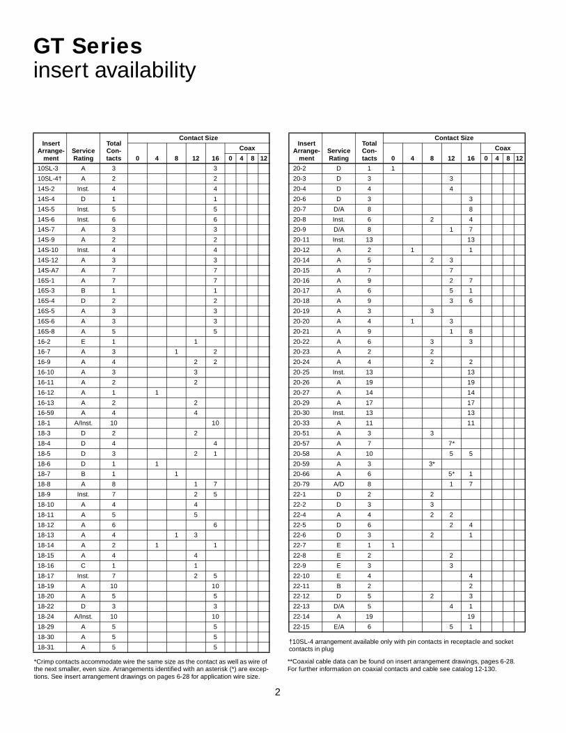
GT Seriesinsert availability
InsertArrange-
mentServiceRating
TotalCon-tacts
Contact Size
0 4 8 12 16
Coax
0 4 8 12
10SL-3 A 3 3
10SL-4† A 2 2
14S-2 Inst. 4 4
14S-4 D 1 1
14S-5 Inst. 5 5
14S-6 Inst. 6 6
14S-7 A 3 3
14S-9 A 2 2
14S-10 Inst. 4 4
14S-12 A 3 3
14S-A7 A 7 7
16S-1 A 7 7
16S-3 B 1 1
16S-4 D 2 2
16S-5 A 3 3
16S-6 A 3 3
16S-8 A 5 5
16-2 E 1 1
16-7 A 3 1 2
16-9 A 4 2 2
16-10 A 3 3
16-11 A 2 2
16-12 A 1 1
16-13 A 2 2
16-59 A 4 4
18-1 A/Inst. 10 10
18-3 D 2 2
18-4 D 4 4
18-5 D 3 2 1
18-6 D 1 1
18-7 B 1 1
18-8 A 8 1 7
18-9 Inst. 7 2 5
18-10 A 4 4
18-11 A 5 5
18-12 A 6 6
18-13 A 4 1 3
18-14 A 2 1 1
18-15 A 4 4
18-16 C 1 1
18-17 Inst. 7 2 5
18-19 A 10 10
18-20 A 5 5
18-22 D 3 3
18-24 A/Inst. 10 10
18-29 A 5 5
18-30 A 5 5
18-31 A 5 5†10SL-4 arrangement available only with pin contacts in receptacle and socket contacts in plug
20-2 D 1 1
20-3 D 3 3
20-4 D 4 4
20-6 D 3 3
20-7 D/A 8 8
20-8 Inst. 6 2 4
20-9 D/A 8 1 7
20-11 Inst. 13 13
20-12 A 2 1 1
20-14 A 5 2 3
20-15 A 7 7
20-16 A 9 2 7
20-17 A 6 5 1
20-18 A 9 3 6
20-19 A 3 3
20-20 A 4 1 3
20-21 A 9 1 8
20-22 A 6 3 3
20-23 A 2 2
20-24 A 4 2 2
20-25 Inst. 13 13
20-26 A 19 19
20-27 A 14 14
20-29 A 17 17
20-30 Inst. 13 13
20-33 A 11 11
20-51 A 3 3
20-57 A 7 7*
20-58 A 10 5 5
20-59 A 3 3*
20-66 A 6 5* 1
20-79 A/D 8 1 7
22-1 D 2 2
22-2 D 3 3
22-4 A 4 2 2
22-5 D 6 2 4
22-6 D 3 2 1
22-7 E 1 1
22-8 E 2 2
22-9 E 3 3
22-10 E 4 4
22-11 B 2 2
22-12 D 5 2 3
22-13 D/A 5 4 1
22-14 A 19 19
22-15 E/A 6 5 1
InsertArrange-
mentServiceRating
TotalCon-tacts
Contact Size
0 4 8 12 16
Coax
0 4 8 12
*Crimp contacts accommodate wire the same size as the contact as well as wire of the next smaller, even size. Arrangements identified with an asterisk (*) are excep-tions. See insert arrangement drawings on pages 6-28 for application wire size.
**Coaxial cable data can be found on insert arrangement drawings, pages 6-28. For further information on coaxial contacts and cable see catalog 12-130.

3
GT Seriesinsert availability, cont.
InsertArrange
mentServiceRating
TotalCon-tacts
Contact Size
0 4 8 12 16
Coax**
0 4 8 12
22-16 A 9 3 6
22-17 D/A 9 1 8
22-18 D/A 8 8
22-19 A 14 14
22-20 A 9 9
22-21 A 3 1 2
22-22 A 4 4
22-23 D/A 8 8
22-24 D/A 6 2 4
22-27 D/A 9 1 8
22-28 A 7 7
22-33 D/A 7 7
22-34 D 5 3 2
22-63 A 12 4 8
22-65 D/A 8 8*
22-70 A 13 8 5
22-80 A 3 3*
24-2 D 7 7
24-3 D 7 2 5
24-5 A 16 16
24-6 D/A 8 8
24-7 A 16 2 14
24-9 A 2 2
24-10 A 7 7
24-11 A 9 3 6
24-12 A 5 2 3
24-16 D/A 7 1 3 3
24-17 D 5 2 3
24-19 A 12 12
24-20 D 11 2 9
24-21 D 10 1 9
24-22 D 4 4
24-27 E 7 7
24-28 Inst. 24 24
24-51 A 5 5
24-52 Hi Volt. 1 1
24-53 A 5 5
24-58 A 13 3 3 7
24-59 A 14 7 7
24-60 A 7 7*
24-65 A 15 11 4
24-66 D 7 7
24-67 Inst. 19 19
24-71 A 7 7*
24-75 A 7 7*
24-79 A 5 5
24-80 Inst. 23 23
24-84 A 19 1 18
24-96 Inst. 28 28
24-AJ A 25 25
28-1 D/A 9 3 6
28-2 D 14 2 12
28-3 E 3 3
28-4 E/D 9 2 7
28-5 D 5 2 1 2
28-6 D 3 3
28-7 D 2 2
28-8 E/D/A 12 2 10
28-9 D 12 6 6
28-10 D/A 7 2 2 3
28-11 A 22 4 18
28-12 A 26 26
28-13 A 26 26
28-15 A 35 35
28-16 A 20 20
28-17 B/D/A 15 15
28-18 C/D/A/Inst. 12 12
28-19 B/D/A 10 4 6
28-20 A 14 10 4
28-21 A 37 37
28-22 D 6 3 3
28-51 A 12 12
28-59 A 17 7 10
28-66 A 16 2 14
28-72 Coax 3 3
28-74 A 16 7* 9
28-75 A 16 7* 9
28-79 A 16 7 9
28-82 D 6 2 4
28-84 A 9 9
28-AY A 9 4 5
32-1 E/D 5 2 3
32-2 E 5 3 2
32-3 D 9 1 2 2 4
32-4 A/D 14 2 12
32-5 D 2 2
32-6 A 23 2 3 2 16
32-7 Inst./A 35 7 28
32-8 A 30 6 24
32-9 D 14 2 12
32-10 E/B/D/A 7 2 2 3
32-12 A/D 15 5 10
32-13 D 23 5 18
32-15 D 8 2 6
32-16 A 23 2 3 2 16
InsertArrange
mentServiceRating
TotalCon-tacts
Contact Size
0 4 8 12 16
Coax**
0 4 8 12
*Crimp contacts accommodate wire the same size as the contact as well as wire of the next smaller, even size. Arrangements identified with an asterisk (*) are excep-tions. See insert arrangement drawings on pages 6-28 for application wire size.
**Coaxial cable data can be found on insert arrangement drawings, pages 6-28. For further information on coaxial contacts and cable see catalog 12-130.

4
InsertArrange-
mentServiceRating
TotalCon-tacts
Contact Size
0 4 8 12 16
Coax**
0 4 8 12
32-17 D 4 4
32-22 A 54 54
32-25 A 25 25
32-31 A 31 31
32-48 Inst. 48 48
32-52 D 8 2 6
32-53 E/Inst. 42 5 37
32-56 A 30 6* 24
32-57 Coax 8 6 2
32-58 Coax 4 4
32-59 A 42 40 2
32-60 A 23 15 8
32-62 Coax 23 2 1 2 16 2
32-64 Inst. 54 54
32-68 A 16 12 4
32-73 A 46 46
32-75 Coax 9 2 7
32-76 A 19 19
32-79 D 5 4 1
32-82 A 16 4 12
32-AF A 55 55
32-AM A 1 1 size 4/0
36-1 D 22 4 18
36-3 D 6 3 3
36-4 D/A 3 3
36-5 A 4 4
36-6 A 6 2 4
36-7 A 47 7 40
36-8 A 47 1 46
36-9 A 31 1 2 14 14
36-10 A 48 48
36-11 A 48 48
36-12 A 48 48
36-13 E/A 17 2 15
36-14 D 16 5 5 6
36-15 D/A 35 35
36-16 A 47 7 40
36-17 A 47 7 40
36-18 A 31 1 2 14 14
36-20 A 34 2 2 30
36-22 D 22 22
36-51 D 4 2 2
36-52 A 52 52
36-54 A 39 8 31
36-55 A 39 8* 31
36-59 A 53 3* 50
36-60 A 47 7* 40
36-64 Coax 4 4
36-65 Coax 4 4
GT Seriesinsert availability, cont.
**Coaxial cable data can be found on insert arrangement drawings, pages 6-28. For further information on coaxial contacts and cable see catalog 12-130.
36-71 A 53 3 50
36-73 Coax 7 7
36-74 A 44 43 1
36-75 A 48 48*
36-76 A 47 47
36-77 D 7 7
36-78 A 14 12 2
36-79 A 20 20
36-80 A 20 20*
36-83 Coax 7 7
36-85 A/D 35 35*
36-97 C 1 1 size 4/0
36-99 D 12 3 3 3 3
36-AF A 48 48
40-1 D 30 6 24
40-5 A 5 5
40-9 A 47 1 22 24
40-10 A 29 4 9 16
40-30 A 30 1 29
40-35 D 35 35
40-53 A 60 60
40-56 A 85 85
40-57 E 4 4
40-61 A 59 1 3 55
40-62 A 60 60
40-63 A 61 61*
40-64 Coax 36 3 20 13
40-66 Coax 4 4
40-67 A 11 1 10
40-68 A 21 21
40-70 A 61 61
40-72 A 11 1 10
40-73 A 61 61
40-74 A 6 1 4 1
40-75 E 5 4 1
40-80 A 11 10 1
40-81 A 62 62*
40-82 A 62 62
40-85 A 60 60*
40-86 Coax 4 4
40-87 D 7 7
40-AD A 8 4 4
40-AG A 38 38
40-AP E 2 2 size 4/0
40-AR Inst. 13 3 3 7
40-AS A 40 25 15
40-AT A 43 1 24 18
40-AU A 14 3 10 1
40-AV D 3 3 size 2/0
InsertArrange-
mentServiceRating
TotalCon-tacts
Contact Size
0 4 8 12 16
Coax**
0 4 8 12
*Crimp contacts accommodate wire the same size as the contact as well as wire of the next smaller, even size. Arrangements identified with an asterisk (*) are exceptions. See insert arrangement drawings on pages 6-28 for applica-tion wire size.

5
GT Seriesinsert alternate positioning
To avoid cross-plugging problems in applications requir-ing the use of more than one connector of the same sizeand arrangement, alternate rotations are available asindicated in the accompanying charts.
As shown in the diagram below, the front face of the pininsert is rotated within the shell in a clockwise directionfrom the normal shell key. The socket insert would berotated counter-clockwise the same number of degreesin respect to the normal shell key.
Position W Position X Position Y Position Z
View looking into front face of pin insert or rear of socket insert.
The following insert arrangements have the same alter-nate insert rotations for W, X, Y and Z, which are:
Degrees
W X Y Z
80 110 250 280
T
16-7 20-16 22-18 24-4 24-28 28-16 32-10
18-5 20-20 22-19 24-5 24-AJ 28-17 32-12
18-9 20-22 22-21 24-6 28-1 28-19 32-13
18-13 22-3 22-24 24-7 28-4 28-20 32-22
18-14 22-6 22-25 24-12 28-8 28-21 32-AF
20-7 22-12 22-29 24-14 28-9 32-1 36-1
20-8 22-14 22-33 24-16 28-10 32-3 36-7
20-9 22-15 22-34 24-17 28-11 32-4 36-8
20-12 22-16 24-1 24-20 28-14 32-6 36-13
20-14 22-17 24-3 24-21 28-15 32-9 40-53
InsertArrangement
Degrees
W X Y Z
10SL-4 63 – – –
14S-2 – 120 240 –
14S-5 – 110 – –
14S-7 90 180 270 –
14S-9 70 145 215 290
16-9 35 110 250 325
16-10 90 180 270 –
16-11 35 110 250 325
16-13 35 110 250 325
16S-1 80 – – 280
16S-4 35 110 250 325
16S-5 70 145 215 290
16S-6 90 180 270 –
16S-8 – 170 265 –
18-1 70 145 215 290
18-3 35 110 250 325
18-4 35 110 250 325
18-8 70 – – 290
18-10 – 120 240 –
18-11 – 170 265 –
18-12 80 – – 280
18-15 – 120 240 –
18-20 90 180 270 –
18-22 70 145 215 290
18-29 90 180 270 –
20-3 70 145 215 290
20-4 45 110 250 –
20-5 35 110 250 325
20-6 70 145 215 290
20-15 80 – – 280
20-17 90 180 270 –
20-18 35 110 250 325
20-19 90 180 270 –
20-21 35 110 250 325
20-23 35 110 250 325
20-24 35 110 250 325
20-27 35 110 250 325
20-29 80 – – 280
20-33 – – – 280
22-1 35 110 250 325
22-2 70 145 215 290
22-4 35 110 250 325
22-5 35 110 250 325
22-8 35 110 250 325
22-9 70 145 215 290
22-10 35 110 250 325
22-11 35 110 250 325
22-13 35 110 250 325
22-20 35 110 250 325
22-22 – 110 250 –
22-23 35 – 250 –
22-27 80 – 250 280
22-28 80 – – 280
24-2 80 – – 280
24-9 35 110 250 325
24-10 80 – – 280
24-11 35 110 250 325
24-22 45 110 250 –
24-27 80 – – 280
24-96 65 – – –
28-2 35 110 250 325
28-3 70 145 215 290
28-5 35 110 250 325
28-6 70 145 215 290
InsertArrangement
Degrees
W X Y Z
*Additional rotations available; consult Amphenol for information.
28-7 35 110 250 325
28-12 90 180 270 –
28-18 70 145 215 290
28-22 70 145 215 290
28-AY 45 110 250 –
32-2 70 145 215 290
32-5 35 110 250 325
32-7 80 125 235 280
32-8 80 125 235 280
32-15 35 110 250 280
32-17 45 110 250 –
32-25 60 120 – –
32-64* 80 100 110 250
32-68 30 – – –
32-82 30 – – –
36-3 70 145 215 290
36-4 70 145 215 290
36-5 – 120 240 –
36-6 35 110 250 325
36-9 80 125 235 280
36-10 80 125 235 280
36-14 90 180 270 –
36-15 60 125 245 305
36-AF 65 – – –
40-1 65 130 235 300
40-5 33 – – 270
40-9 65 125 225 310
40-10 65 125 225 310
40-35 70 130 230 290
40-56 72 144 216 288
40-AG 37 74 285 322
InsertArrangement
Degrees
W X Y Z
AB
AB A
B
AB

6
ABC
AB A
BC
DA
B
C
D
E
F A
B
CD
E A
B
C
AB100˚
A
BC
D
100˚
A
B
C
A
B
CD
E
F
G
AB
A
BC
A
B
C A
BC
D
E A B
C
A
B
C
D
A
F
ED
C
BG
front face of pin insert or rear face of socket insert illustrated
GT Seriescontact arrangements
Insert Arrangement 10SL-3 10SL-4 14S-2 14S-4 14S-5
Service Rating A A Inst. D Inst.
Number of Contacts 3 2 4 1 5
Contact Size 16 16 16 16 16
Insert Arrangement 14S-6 14S-7 14S-9 14S-10 14S-12
Service Rating Inst. A A Inst. A
Number of Contacts 6 3 2 4 3
Contact Size 16 16 16 16 16
Insert Arrangement 14S-A7 16S-1 16S-3 16S-4 16S-5
Service Rating A A B D A
Number of Contacts 7 7 1 2 3
Contact Size 16 16 16 16 16
Insert Arrangement 16S-6 16S-8 16-2 16-7 16-9
Service Rating A A E A A
Number of Contacts 3 5 1 1 2 2 2
Contact Size 16 16 12 8 16 12 16
CONTACT LEGEND 16 12 8 4 0
Front ofSocket Insert
Front ofSocket Insert
100° Rotationof 14S-2
100° Rotationof 14S-7

7
A
B
AB
AB
A
BC
DA
BC
A
B
CD
E
FG
H
A
B
C
D
E
F
G
A
BC
DA
BC
D
E
A
B
C
D
EF
A
B
C
D
A
B
A
B
C
D
100˚
A
B
C
D
E
F
G
A
B CD E F G
H
K
J
A B
CD
E
front face of pin insert or rear face of socket insert illustrated
GT Seriescontact arrangements
Insert Arrangement 16-10 16-11 16-12 16-13 16-59
Service Rating A A A A A
Number of Contacts 3 2 1 2* 4
Contact Size 12 12 4 12 12
Insert Arrangement 18-1 18-3 18-4 18-5 18-6 18-7
Service Rating B, C, F, G = A; Bal. = Inst. D D D D B
Number of Contacts 10 2 4 2 1 1 1
Contact Size 16 12 16 12 16 4 8
Insert Arrangement 18-8 18-9 18-10 18-11 18-12 18-13
Service Rating A Inst. A A A A
Number of Contacts 1 7 2 5 4 5 6 1 3
Contact Size 12 16 12 16 12 12 16 8 12
Insert Arrangement 18-14 18-15 18-16 18-17 18-19 18-20
Service Rating A A C Inst. A A
Number of Contacts 1 1 4** 1 2 5 10 5
Contact Size 4 16 12 12 12 16 16 16
CONTACT LEGEND 16 12 8 4 0
* A = Iron; B = Constantan**A, C = Iron; B, D = Constantan
100° Rotationof 18-9
A
B
C
DE
F
G
H
I
J
B
C AA B
C D

8
110˚A B
CD
E
A
BC
A
BC
A
B
C
DE
F
GH
A
B
C
D
E F
A
B
C
DE
F
G H
A
B C
D
E
F
G H
J
K
L
M
N
A
B
A
B
C
D
E A
B
CD
E G
F
AB
C
D
EF
G
HI
A
BC
D
E
F
260˚
A B
CD
E
front face of pin insert or rear face of socket insert illustrated
GT Seriescontact arrangements
Insert Arrangement 18-22 18-24 18-29 18-30 18-31 20-2
Service Rating D B, C, F, G = A; Bal. = Inst. A A A D
Number of Contacts 3 10 5 5 5 1
Contact Size 16 16 16 16 16 0
Insert Arrangement 20-3 20-4 20-6 20-7 20-8 20-9
Service Rating D D D A, B, H, G = D; C, D, E, F = A Inst. H = D; Bal. = A
Number of Contacts 3 4 3 8 2 4 1 7
Contact Size 12 12 16 16 8 16 12 16
Insert Arrangement 20-11 20-12 20-14 20-15 20-16 20-17
Service Rating Inst. A A A A A
Number of Contacts 13 1 1 2 3 7 2 7 5 1
Contact Size 16 4 16 8 12 12 12 16 12 16
CONTACT LEGEND 16 12 8 4 0
110° Rotationof 18-20
A
BC
D
E
A
B
D
C
250˚
A
B
C
DE
F
G
H
I
JA B
G
250° Rotationof 18-1
260° Rotationof 18-20

9
A
B
C
D
A
B
C
DE
F
G
H
I A
B
C
D
E
FA
B
A
B
C
D
100˚
A
B C
D
E
F
G H
J
K
L
M
N
AB
CD
EF
G
H
IJ
K
L
M
N
A BC
D
E
FGH
J
K
L
MN
PT
S R
250˚A
B C
D
E
F
G H
J
K
L
M
N
AB
C
D
EF
K
H
JM
L
front face of pin insert or rear face of socket insert illustrated
GT Seriescontact arrangements
Insert Arrangement 20-18 20-19 20-20 20-21 20-22 20-23
Service Rating A A A A A A
Number of Contacts 3 6 3 1 3 1 8 3 3 2
Contact Size 12 16 8 4 12 12 16 8 16 8
Insert Arrangement 20-24 20-25 20-26 20-27 20-29 20-30
Service Rating A Inst. A A A Inst.
Number of Contacts 2 2 13 19 14 17 13
Contact Size 8 16 16 16 16 16 16
Insert Arrangement 20-33 20-51 20-57 20-58 20-59 20-66
Service Rating A A A A A A
Number of Contacts 11 3* 7* 5 5 3* 1 5
Contact Size 16 8 12 for #14 or 16 wire 12 16 8 for #10 or 12 wire 16 12 for #10 wire
* Solderless CONTACT LEGEND 16 12 8 4 0
250° Rotationof 20-11
100° Rotationof 20-11
A
BC
A
B
C
D
E
F
GH
I
A
BC
D
EF
G
H S R
JT
VP
K
LM
U N
A
B
CA
B
CD
E G
FA
BC
D E
F
HJ
K
L
A
B
C A
BC
D
E
F

10
A
BC
A
BC
D
AB
A
B
CD
E A
BC
DE
A
B
C
D
EF
G
H
J
K
L M
NU
V
RS
T P
A
B
E
F
CD
front face of pin insert or rear face of socket insert illustrated
GT Seriescontact arrangements
Insert Arrangement 20-79 22-1 22-2 22-4 22-5
Service Rating H=D; Bal. = A D D A D
Number of Contacts 7* 1* 2 3 2 2 2 4
Contact Size 16 12 for #16 wire 8 8 8 12 12 16
Insert Arrangement 22-6 22-7 22-8 22-9 22-10
Service Rating D E E E E
Number of Contacts 2 1 1 2 3 4
Contact Size 8 16 0 12 12 16
Insert Arrangement 22-11 22-12 22-13 22-14 22-15
Service Rating B D E = D; A, B, C, D = A A D = E; A, B, C, E, F = A
Number of Contacts 2 2 3 4 1 19 5 1
Contact Size 16 8 16 12 16 16 12 16
* Solderless CONTACT LEGEND 16 12 8 4 0
A
B
C
D
A
B
CD
E
F
A
B
C
AB
AB
A
BC
A
B
C
DE
F
G
H

11
A
B
C
D
E
F
AB
C
D
E
F
G
H
J
A
B
C
E
F
G
D
A
BCE
FG
D A
BC
DE
front face of pin insert or rear face of socket insert illustrated
GT Seriescontact arrangements
Insert Arrangement 22-16 22-17 22-18 22-19 22-20
Service Rating A A = D; Bal. = A A, B, F, G, H = D; C, D, E = A A A
Number of Contacts 3 6 1 8 8 14 9
Contact Size 12 16 12 16 16 16 16
Insert Arrangement 22-21 22-22 22-23 22-24 22-27
Service Rating A A H = D; Bal. = A C, D, E = D; A, B, F = A J = D; Bal. = A
Number of Contacts 1 2 4 8 2 4 1 8
Contact Size 0 16 8 12 12 16 8 16
Insert Arrangement 22-28 22-33 22-34 22-63 22-65
Service Rating A A, B, C, D = D; E. F. G = A D A H = D; Bal. = A
Number of Contacts 7 7 3 2 4 8 8*
Contact Size 12 16 12 16 12 16 12 for #14 or 16 wire
* Solderless CONTACT LEGEND 16 12 8 4 0
A
B
C
D
E
F G H
J
AB
C
D
E
F
G
H
J
A
B
C
D
E
F
G
H
AB
C
D
EF
G
H
J
KL
M
N
P
A
B
CDE
F
G H
J
A
B
C A
BC
DA
B
CD
E
FG
H
A
B C
EF
HJ
K
L
MN
D
A
B
CD
E
FG
H

12
AB
C
D
E
AB
C
D
EF
G
H
J
K L
A
B
C
D
EFH
J
K
L
M
N
front face of pin insert or rear face of socket insert illustrated
GT Seriescontact arrangements
Insert Arrangement 22-70 22-80 24-2 24-3 24-5
Service Rating A A D D A
Number of Contacts 8 5 3* 7 2 5 16
Contact Size 12 16 8 for #10 or 12 wire 12 12 16 16
Insert Arrangement 24-6 24-7 24-9 24-10 24-11
Service Rating A, G, H = D; Bal. = A A A A A
Number of Contacts 8 2 14 2 7 3 6
Contact Size 12 12 16 4 8 8 12
Insert Arrangement 24-12 24-16 24-17 24-19 24-20
Service Rating A A, B, F, G = D; C, D, E = A D A D
Number of Contacts 2 3 1 3 3 2 3 12 2 9
Contact Size 4 12 8 12 16 12 16 16 12 16
* Solderless CONTACT LEGEND 16 12 8 4 0
A
B
CD
E
F
G
A
B
C
E
F
G
D
A BC
D EF G H
J KL M N
PS
R
AB
C
D
E
F
G
H
AB
C
D
E
FG
H
J
KL
M
NP
I O
AB
A
B
CD
E
FG
A B C
D E F
G
H
I
A
B
C
D
E
A
B
C
D
E
FG
A
B
C
DE
F
H
JK
LM
N
P
A
BC
13
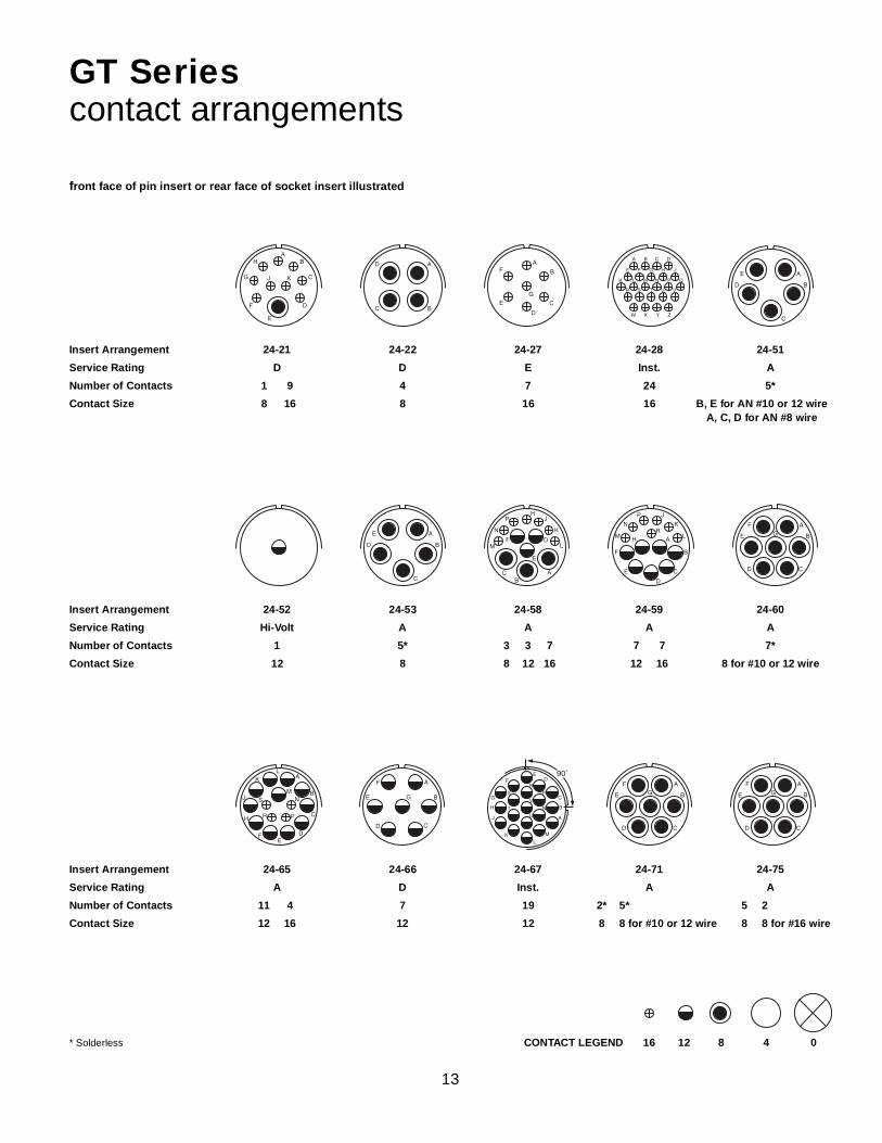
front face of pin insert or rear face of socket insert illustrated
GT Seriescontact arrangements
Insert Arrangement 24-21 24-22 24-27 24-28 24-51
Service Rating D D E Inst. A
Number of Contacts 1 9 4 7 24 5*
Contact Size 8 16 8 16 16 B, E for AN #10 or 12 wireA, C, D for AN #8 wire
Insert Arrangement 24-52 24-53 24-58 24-59 24-60
Service Rating Hi-Volt A A A A
Number of Contacts 1 5* 3 3 7 7 7 7*
Contact Size 12 8 8 12 16 12 16 8 for #10 or 12 wire
Insert Arrangement 24-65 24-66 24-67 24-71 24-75
Service Rating A D Inst. A A
Number of Contacts 11 4 7 19 2* 5* 5 2
Contact Size 12 16 12 12 8 8 for #10 or 12 wire 8 8 for #16 wire
* Solderless CONTACT LEGEND 16 12 8 4 0
A B C D
E F G H J
K L M N P Q
R S T U V
W X Y Z
AB
C
D
E
F
G
H
J K
A
BC
D A
B
C
D
E
F
G
A
B
C
D
E
F
H
J
K
LM
N
P
RA
B
CD
E
FG
A
B
C
DE
F
H
J
KL
MN
PR
S
A
B
CD
E
F
G
90˚
A
B
C
DE
F
G
H
J
KL
M
N
P
R
S
TU
V
A
B
CD
E
FG
A
B
C
D
E
A
B
C
D
E
AB
C
D
E
F
HJ
K
LM
N
P
A
B
CD
E
FG
14
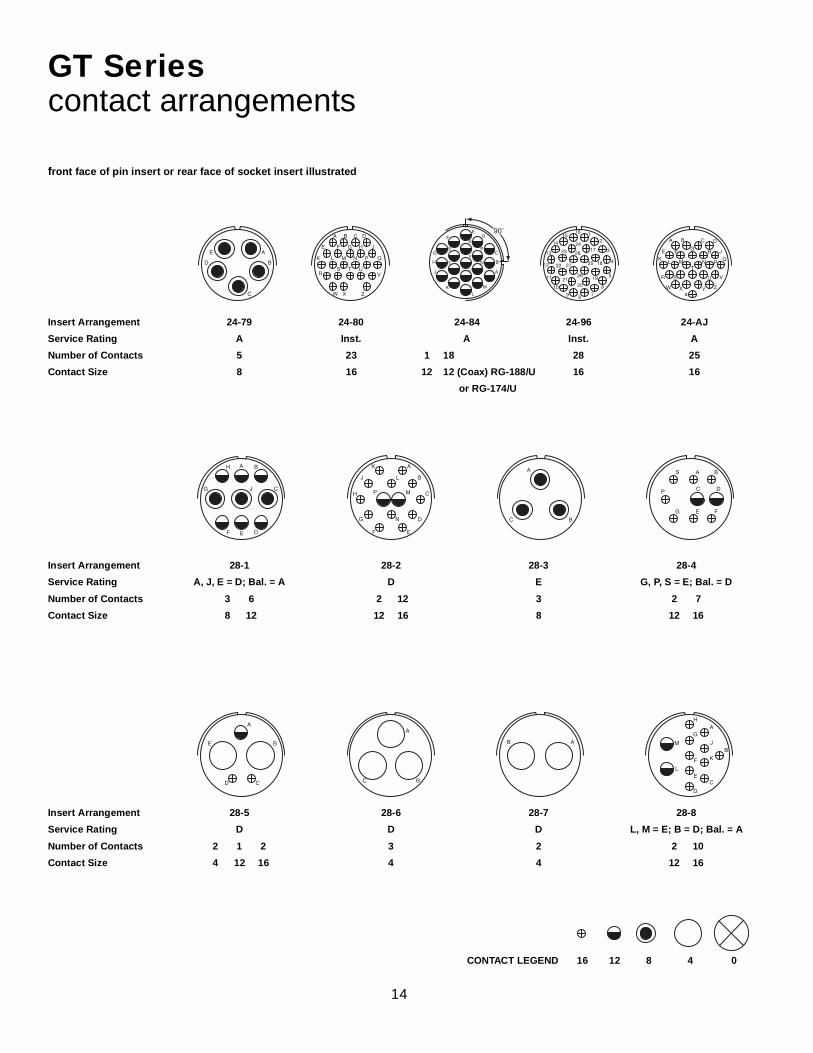
front face of pin insert or rear face of socket insert illustrated
GT Seriescontact arrangements
Insert Arrangement 24-79 24-80 24-84 24-96 24-AJ
Service Rating A Inst. A Inst. A
Number of Contacts 5 23 1 18 28 25
Contact Size 8 16 12 12 (Coax) RG-188/U 16 16
or RG-174/U
Insert Arrangement 28-1 28-2 28-3 28-4
Service Rating A, J, E = D; Bal. = A D E G, P, S = E; Bal. = D
Number of Contacts 3 6 2 12 3 2 7
Contact Size 8 12 12 16 8 12 16
Insert Arrangement 28-5 28-6 28-7 28-8
Service Rating D D D L, M = E; B = D; Bal. = A
Number of Contacts 2 1 2 3 2 2 10
Contact Size 4 12 16 4 4 12 16
CONTACT LEGEND 16 12 8 4 0
A B
C
DEF
G
H
J
A
B
C
D
EF
G
H
J
K
L
M
N
P
A
BC
A B
C DP
S
E FG
A
B
CD
E
A
BC
AB
A
B
C
D
E
A B C D
E F G H J
K L M N P Q
RS T U
V
W X Z
90˚
A
B
C
DE
F
G
H
J
KL
M
N
P
R
S
TU
V
12
3
4
5
6
789
10
11
12
13
14
1516
17
18
1920
21
22
23
24
25
26
27
28
A B C D
E FG
H JK
L M N PQ
R S
T
U V
W X ZYa
A
B
C
D
E
F
G
H
J
K
L
M

15
front face of pin insert or rear face of socket insert illustrated
GT Seriescontact arrangements
Insert Arrangement 28-9 28-10 28-11 28-12
Service Rating D G = D; Bal. = A A A
Number of Contacts 6 6 2 2 3 4 18 26
Contact Size 12 16 4 8 12 12 16 16
Insert Arrangement 28-13 28-15 28-16 28-17
Service Rating A A A R = B; M, N, P = D; A to L = A
Number of Contacts 26 35 20 15
Contact Size 16 16 16 16
Insert Arrangement 28-18 28-19 28-20
Service Rating M = C; G, H, J, K,L = D; A, B = A; Bal. = Inst. H, M = B; A, B, = D; Bal. = A A
Number of Contacts 12 4 6 10 4
Contact Size 16 12 16 12 16
* Solderless CONTACT LEGEND 16 12 8 4 0
A
B
C
DE
F
G
HJ
K
LM
A
B
CD
E
F
GA
B
C
D
E
F
G
H
J
K
L
MI
N
P
R
S
T
U
V
W
X
A
B
C
D
E
F
GH
JK
L
M
PR
N
ST
U
V
WX
Y
Z
a
b
d
100˚ A
B
C
D
E
F
GH
JK
L
M
PR
N
ST
U
V
WX
Y
Z
a
b
d
A
B
CD
E
FG
H J K
L
M
N
P
R
AB
C
D
E
FG
H
J
K
L
M
A B
C
E
GH
J
K
L
M
A BC D E F G
H J K L M
P R S T
N
W
X Y Z
U V
a b c
de
f
gh
j k
ml
AB
C
D
EFG
H
J
K
L M
PQR
S
T
UV N
A
B
C
D
EF
G
H
J
K
LM
NP
100° Rotationof 32-6

16
front face of pin insert or rear face of socket insert illustrated
GT Seriescontact arrangements
Insert Arrangement 28-21 28-22 28-51 28-59
Service Rating A D A A
Number of Contacts 37 3 3 12 7 10
Contact Size 16 4 16 12 12 16
Insert Arrangement 28-66 28-72 28-74 28-75
Service Rating A – A A
Number of Contacts 2 14 3 9* 4* 3* 9* 7*
Contact Size 8 12 4 (Coax) RG-59A/U 16 8 8 for #10 wire 16 8 for #10 wireor RG-62A/U (S, T, R)
Insert Arrangement 28-79 28-82 28-84 28-AY
Service Rating A D A A
Number of Contacts 7 9 2 4 9 4 5
Contact Size 8 16 8 12 8 4 16
* Solderless CONTACT LEGEND 16 12 8 4 0
A
B
C
DE
F
A
B
C
DE
F
H
J
K
L
M
N A B C D
EF
H
J K
L M N
P R S T U
AB
C
D
E
F
HJ
K
L
M
N
PR
S
T
A
BC
AB
CD
EFH
J
K
L
MN
PR
S
T
AB
CD
EFH
J
K
L
MN
PR
S
T
AB
CD
EFH
J
K
L
MN
PR
S
T1 23
4 5
6
A
B
C
DE
F
G
H
I
AB C
DE F G H J
K L M N P R
S T U V W X Z
a b c d e f
gh
jk m
n p r s
AB C
D E F
G H
J

17
front face of pin insert or rear face of socket insert illustrated
GT Seriescontact arrangements
CONTACT LEGEND 16 12 8 4 0
Insert Arrangement 32-1 32-2 32-3 32-4
Service Rating A = E; B, C, D, E = D E D F, J, K, N = A:, Bal. = D
Number of Contacts 2 3 3 2 1 2 2 4 2 12
Contact Size 0 12 4 16 0 4 12 16 12 16
Insert Arrangement 32-5 32-6 32-7
Service Rating D A A, B, h, j = Inst.; Bal. = A
Number of Contacts 2 2 3 2 16 7 28
Contact Size 0 4 8 12 16 12 16
Insert Arrangement 32-8 32-9 32-10
Service Rating A D A, F = E; G = B; B, E = D; C, D = A
Number of Contacts 6 24 2 12 2 2 3
Contact Size 12 16 4 16 4 8 16
A
B
CD
E
A
B
C
D
E
AB
C
D E F
G
H
J
A
B
A B
C DE FG H
JK L M N
O
P R
ST
U V
W
I
X
A
B
C
D
E
F
G
H
I
J
K
L
M
N
O
P
R
S
T
U
V
W
X
Y
Z
a
b
c
d
e
f
g
h
j
k
A B
C D E F G
H I J K
L M N
A
B
C
D
E
F
G
H
J
K
L
M
N
O
A
B
C
D
E
F
G
H
I
J
K
L
M
N
O
P
R
S
T
U
V
W
X
Y
Z
a
b
c
d
e
A
B
CD
E
F
G

18
GT Seriescontact arrangements
A
B C
D E
F
G
H
100˚A B
C D
E FG H
I J
K L M N
O
P R
ST
U V
W X
A
BC
D
A BC D E
F G H J
K L MN O P R
S T U V WX Y Z a
b c d e f
g h j km n p r
tq
s u vx y
z AAAB AC
AD AE
AF AG
w
100° Rotationof 32-6
Insert Arrangement 32-12 32-13 32-15 32-16
Service Rating C, D, E, F, G = A; Bal. = D D D A
Number of Contacts 5 10 5 18 2 6 2 3 2 16
Contact Size 12 16 12 16 0 12 4 8 12 16
Insert Arrangement 32-17 32-22 32-25 32-31
Service Rating D A A A
Number of Contacts 4 54 25 31
Contact Size 4 16 12 16
Insert Arrangement 32-48 32-52 32-53 32-56
Service Rating Inst. D t, u = E; Bal. = Inst. A
Number of Contacts 48 2 6 5 37 24 6
Contact Size 16 0 12 12 16 16 12 for #10 wire
1312
11
10
9
87
6
5
4
3
21
23
19 2221
20
15
18
1716
14
2425
90˚ A
B C
D E
F
G
H A B C D E
F
H
J
KL
M N PR
S
T
U
VW
X
YZ
a b cd
f
gh
ij k
m
np
r
t uv w
s
q
1
2
3
4
5
6
7
8
9
10
11
12
13
14
15
16
17
18
19
20
21
22
23
24
25
26 27
28
29
30 31
90° CW Rotationof 32-15
A BC D E F H
J K L M N P
R S T U V W X
Y Z a b c d f g
h i j k m n p
q r s t u v
w x y z AA
BB CC
A
B
C
D
E
F
G
H
J
K
L
M
N
PR
S
T
U
V
W
XY
Z
A B
C D E F G
H J K
L M
O P
N
A
B
C
D
E
F
G
H
I
J
K
L
M
N
O
P
R
S
T
U
V
W
X
Y
Z
a
b
c
d
e
CONTACT LEGEND 16 12 8 4 0
front face of pin insert or rear face of socket insert illustrated

19
CONTACT LEGEND 16 12 8 4 0
** Consult Amphenol, Sidney, NY for service rating of power contacts.
front face of pin insert or rear face of socket insert illustrated
GT Seriescontact arrangements
Insert Arrangement 32-57 32-58 32-59 32-60
Service Rating ** – A A
Number of Contacts 6 2 4 40 2 15 8
Contact Size 12 0 (Coax) RG-71/U 4 (Coax) RG-161/U 16 8 (Coax) RG-161/U 16 8 (Coax) RG-124/Uor RG-179/U
Insert Arrangement 32-62 32-64 32-68
Service Rating ** Inst. A
Number of Contacts 2 1 2 16 2 54 12 4
Contact Size 4 8 12 16 8 (Coax) RG-124/U 16 16 4 (Coax) RG-58C/U
Insert Arrangement 32-73 32-75 32-76 32-79
Service Rating A 8, 9 = D A D
Number of Contacts 46 2 7 19 4 1
Contact Size 16 12 8 (Coax) RG-180B/U 12 4 8
A B
C DE FG H
JK L M N
O
P R
ST
U V
W
I
X
A B
C D EF G H J
K L MN O P R
S T U V W
X Y Z ab c d e f
g h j km n p r
t u vw
sx y
z
q
AAAB AC
AD AEAF AG
A B
CD
E
F G H
J
K L M
N P
Q R
12
3
4
5
6
7
8
91011
12
13
14
15
16
17
18
1920 21
22
23
24
25
26
27
282930
31
32
33
34
35
36
37
38
39
4041
42
43
44
45
46
1
2
3
4
5
6 7
8 9
1 2 3
4 5 6 7
8 9 10 11 12
13 14 15 16
17 18 19
A
BC
D
E
A
BC
D
A
B
CD
E
F
H
J
K
LM
N
P
R
S
T
U
VW
X
Y
Z
a
A
B C
D E
F
G
H
AB
C
D
E
F
H
JK
LMN
PR
S
T
U
V
W
XY
T
U
Z
a
b
c
d
fgh
i
j
k
m
n
pq
w
vs
t

20
A B
CD
E
F GH I J
K L M NO P R S T
U V W X
Y Z a b c
d e f gh j k m
n p
r
t
s
u v
x y
z
w
AB C
D EFG H
I J K LMN
O P RS
T UV
WX
YZ
a
b c d e
f g h jk
mn p r
tuv w
s
x yz
front face of pin insert or rear face of socket insert illustrated
GT Seriescontact arrangements
Insert Arrangement 32-82 32-AF 32-AM 36-1
Service Rating A A A D
Number of Contacts 4 12 55 1 4 18
Contact Size 4 16 16 4/0 12 16
Insert Arrangement 36-3 36-4 36-5
Service Rating D A = D; B, C = A A
Number of Contacts 3 3 3 4
Contact Size 0 12 0 0
Insert Arrangement 36-6 36-7 36-8
Service Rating A A A
Number of Contacts 2 4 7 40 1 46
Contact Size 0 4 12 16 12 16
CONTACT LEGEND 16 12 8 4 0 4/0
.
A B C
D E F G H
I J K L M N
O P R S T
U V W
A
B
CD
E
FA
BC
A
B
C
D
A
B
C
D
E
F
A BC D E
F G H JK L M
N O P RS T U V W
X Y Z a
b c d e fg h j k
nm p rt u v
ws
x y
z
q
AAAB AC
AD AEAF AG
AH
A B
CD
E
F G H
J
K L M
N P
Q R

21
110˚
A B
CD
EF G
H I JK L M N
O P R ST
U V W XY Z a b c
d ef g
h j km
n p
r
tu v
ws
x y
z
Insert Arrangement 36-9 36-10 36-11
Service Rating A A A
Number of Contacts 1 2 14 14 48 48
Contact Size 4 8 12 16 16 16
Insert Arrangement 36-12 36-13 36-14
Service Rating A N, P, Q = E; Bal. = A D
Number of Contacts 48 2 15 5 5 6
Contact Size 16 12 16 8 12 16
Insert Arrangement 36-15 36-16 36-17
Service Rating M = D; Bal. = A A A
Number of Contacts 35 7 40 7 40
Contact Size 16 12 16 12 16
110° Rotationof 36-7
front face of pin insert or rear face of socket insert illustrated
GT Seriescontact arrangements
CONTACT LEGEND 16 12 8 4 0
A B
C D E F G
H J K L M N
O P Q R S T U
V W X Y Z a b c
d e f g h j k
m n p r
t u v w
s
x
y z
q
100˚
A B
C D E F G
H J K L M N
O P Q R S T U
V W X Y Z a b c
d e f g h j k
m n p r
t u v w
s
x
y z
q
110˚
A B
C D E F G
H J K L M N
O P Q R S T U
V W X Y Z a b c
d e f g h j k
m n p r
t u v w
s
x
y z
q
A
B
C
DEF
G
H
J
K
LM
NP
Q
R S
A
B
C
D
E
F
G
H
J
K
L
M
N
I P
Q
A
B
C
D
E
F
G
HJ
K
L
M
N
P
Q
R
S
TU
V
W
X
YZ
a
b
c
d
e
f
gh
j
k
m
100° Rotationof 36-10
110° Rotationof 36-10
A
B
C
D
E
F
G
H
I
J
K
L
M
N
O
P
R
S
T
U
V
W
X
Y
Z
a
b
c
d
e
f
100˚A B
C D EF G
H I JK
L MN
OP R S
T
U V W XY Z a b c
d e f g
h j kmn p
r
t
u vw
s
x y
z
100° Rotationof 36-7

22
A
B
CD
AB
C
D
E
F
H
J
K
LM
NPR
S
T
U
V
W
X
Y
Za b
c
d
f
g
h
ij
km
n
p
r t
s
q
AB
C
D
E
F
H
J
K
LM
NPR
S
T
U
V
W
X
Y
Za b
c
d
f
g
h
ij
km
n
p
r t
s
q
A B C D
E F H J K
L M N P R S T U
V W XY Z a b
c d f g h i j k
m n p r t
u v w
s
x y z
q
AA AB
AC
AD
AE
AF
AH
AJ
A B
CD
E
F GH I J
K L M NO P R S T
U V W X
Y Z a b c
d e f gh j k m
n p
r
t
s
u v
x y
z
w
1
2
3
4
5
6
78
9
10
11
12
13
14
15
16
17
20
21
22
19
18
front face of pin insert or rear face of socket insert illustrated
GT Seriescontact arrangements
Insert Arrangement 36-18 36-20 36-22
Service Rating A A D
Number of Contacts 1 2 14 14 2 2 30 22
Contact Size 4 8 12 16 8 12 16 12
Insert Arrangement 36-51 36-52 36-54
Service Rating D A A
Number of Contacts 2 2 52 8 31
Contact Size 0 4 16 8 16
Insert Arrangement 36-55 36-59 36-60
Service Rating A A A
Number of Contacts 31 8 50 3 40 7
Contact Size 16 8 for #6 wire 16 12 for #10 wire 16 12 for #10 wire
CONTACT LEGEND 16 12 8 4 0
A B
C D E F G
H J K L M N
P R S T U V W
X Y Z a b c
d e f gh j
k m
A B C D
E F H J K
L M N P R S
T U V W X Y Z
a b c d f g h i
j k m n p r
t u v ws x
y z
q
AA ABAC
AD
AE AF
AH
100˚
A
B
C
D
E
F
G
H
I
J
K
L
M
N
O
P
R
S
T
U
V
W
X
Y
Z
a
b
c
d
e
f
100° Rotationof 36-9
23
48 4950 51 52
53 5455 56 57
58 59 60 6162 63 64 65 66
67 68 69 7071 72 73 74 75
76 77 78 7980 81 82 83
84 8586 87
88 8990
91
1 2
3 4 5
6 7
89
10 11
1213
1415
16
17
18
19
202122
2324
25
2627
28
29
30
31 32
33 34
3536
37
38
394041
42 43
4445
4647
48
1 23
4 56 7 8
9 10 11 1213 14 15 16 17
18 19 20 2122 23 24 25 26
27 28 29 3031 32 33 34 35
36 37 38 3940 41 42
43 4445
46 47
A
B
C
D
E
F
G
1
2
3
4
56
7
8
9
10
11
12
13
14
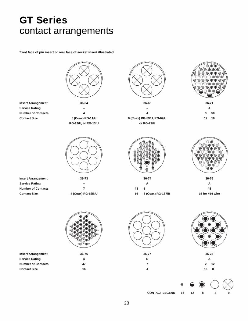
front face of pin insert or rear face of socket insert illustrated
GT Seriescontact arrangements
Insert Arrangement 36-64 36-65 36-71
Service Rating – – A
Number of Contacts 4 4 3 50
Contact Size 0 (Coax) RG-11/U 0 (Coax) RG-59/U, RG-62/U 12 16
RG-12/U, or RG-13/U or RG-71/U
Insert Arrangement 36-73 36-74 36-75
Service Rating – A A
Number of Contacts 7 43 1 48
Contact Size 4 (Coax) RG-62B/U 16 8 (Coax) RG-187/B 16 for #14 wire
Insert Arrangement 36-76 36-77 36-78
Service Rating A D A
Number of Contacts 47 7 2 12
Contact Size 16 4 16 8
CONTACT LEGEND 16 12 8 4 0
A
B
C
D
A B C D
E F H J K
L M N P R S T U
V W XY Z a b
c d f g h i j k
m n p r t
u v w
s
x y z
q
AA AB
AC
AD
AE
AF
AH
AJ
A
B
C
D
E
F
G
A
B
C
D

24
AB
C
D
E
F
GHJ
KL
M
N
OP
Q
R
S
T
UV
W
X
Y
Z
ab
c
d ef
g
h
j
k
m
npr
ts
q
u
v
w
x
y
z
A
B
GC
N
1
2
3
4
5
6
7
8
910
11
12
front face of pin insert or rear face of socket insert illustrated
GT Seriescontact arrangements
Insert Arrangement 36-79 36-80 36-83
Service Rating A A –
Number of Contacts 20 20 7
Contact Size 12 12 for #10 wire 4 (Coax) RG-58/U
Insert Arrangement 36-85 36-97 36-99
Service Rating M = D; Bal. = A C D
Number of Contacts 35 1 3 3 3 3
Contact Size 16 for #12 wire 4/0 4 8 12 16
Insert Arrangement 36-AF 40-1 40-5
Service Rating A D A
Number of Contacts 48 6 24 5
Contact Size 16 12 16 0
CONTACT LEGEND 16 12 8 4 0 4/0
1
2 3 4 5
6 7 8 9 10
11 12 13 14 15
16 17 18 19
20
A
B
C
D
E
F
G
A
B
C
D
E
F
GHJ
K
L
M
N
P
Q
RS
T
U
V
W
XYZ
a
b
c
d
f
gh
j
k
m
e
A B C
D E F G
H I J K L
M N O P R S
T U V W X
Y Z a b
c d e
1
2 3 4 5
6 7 8 9 10
11 12 13 14 15
16 17 18 19
20

25
12
3
4
5
6
7
8
9
1011
12
13
14
15
16
17
18
19
20
21
22
23
24
25
26
27
28
29
30
front face of pin insert or rear face of socket insert illustrated
GT Seriescontact arrangements
Insert Arrangement 40-9 40-10 40-30
Service Rating A A A
Number of Contacts 1 22 24 4 9 16 29 1
Contact Size 8 12 16 4 8 16 12 4
Insert Arrangement 40-35 40-53 40-56
Service Rating D A A
Number of Contacts 35 60 85
Contact Size 12 16 16
Insert Arrangement 40-57 40-61 40-62
Service Rating E A A
Number of Contacts 4 1 3 55 60
Contact Size 0 8 12 16 16
CONTACT LEGEND 16 12 8 4 0
1 2
3 4 5 6 7
8 9 10 11 12 13 14 15
16 17 18 19 20 21 22 23 24
25 26 27 28 29 30 31 32
33 34 35 36 37 38 39 40 41
42 43 44 45 46 47 48 49
50 51 52 53 54 55 56
57
58
59
12
34
5
6
7
8
910
1112
1314
1516
17
18
19
20
2122
2324
2526
2728
29
30
3132
333536
37
38
39
4041
4243
4445
46
47
34
4849
5051
52
5354
5556
5758
59
60
1
2
3
4
5
6
7
89
10
11
12
13
14
1516
17 18
19
20
21
222324
25
26
27
28
29
30
3132
33
34
35
12
3
4
5
6
7
8
9
1011
121314
15
16
17
18
19
20
21
22
2324
2526
27
28
29
30
31
3233
343536
37
38
39
40
4142
4344
45
46
47
484950
51
52
53
54
55
56
57
5859
60
1
2
3
4
A B C D
E F H J K L M
N P R S T U V W
X Y Z a b c d f g
h i j k m n p r
t u v w
s
x y z
q
AA AB
AC AD AE AF AH AJ AK AL AM AN
AP AR AS AT AU AV AW AX AY
AZ BA BB
BV
BC BD BE BF BH
BJ BK BL BM BN
BS BT BU
BP BR
ABC D
E
HK
GJF
L
QPN
I
M
R S
O
V
Y
Z
W
U
X
b
a
c
T
A BC
D EF
G HI J K L
M N O P Q R S T
U V W X Y Z a
b c de f
g h i
jk
l m
n
pr
t us
o
q

26
front face of pin insert or rear face of socket insert illustrated
GT Seriescontact arrangements
Insert Arrangement 40-63 40-64 40-66
Service Rating A – –
Number of Contacts 61 3 20 13 4
Contact Size 16 for #14 wire 12 16 8 (Coax) RG-124/U 0 (Coax) RG-63 B/U
Insert Arrangement 40-67 40-68 40-70
Service Rating A A A
Number of Contacts 1 10 21 61
Contact Size 16 4 (Coax) RG-59/U 8 16
Insert Arrangement 40-72 40-73 40-74
Service Rating A A A
Number of Contacts 1 10 61 1 1 4
Contact Size 16 4 (Coax) RG-9B/U 16 12 4 (Coax) RG-62/U 0 (Coax) RG-9B/Uor RG-214/U
CONTACT LEGEND 16 12 8 4 0
1
2
3
4
A B
C D E
F H J
K LM
A
B
C
D
E
F
G
H
J
K
L
M
N
P
R
S
TU
V
W
X
1
2 3 4 5
6 7 8 9 10
11 12 13 14 15 16 17 18
19 20 21 22 23 24 25 26 27
28 29 30 31 32 33 34 35
36 37 38 39 40 41 42 43 44
45 46 47 48 49 50 51 52
53 54 55 56 57
58 59 60 61
A B
C D E
F H J
K LM
12
3
4
5
6
7
8
9
10
111213
1415
16
17
18
19
20
21
2223
24
25 2627
28
29
30
31
32
3334
35
36
37
38
39
40
4142
43 44
45
46
47
48
49
50
51
52
53
54
5556
57
58
59
6061
1
2
34
5
6
A
B
C
D
E
F
H
J
K
L
M
N
P
RS
T
U
V
W
X
YZa
b
c
d
f
gh
i
j
km
n
p
q
12
3
4
5
6
7
8
9
10
111213
1415
16
17
18
19
20
21
2223
24
25 2627
28
29
30
31
32
3334
35
36
37
38
39
40
4142
43 44
45
46
47
48
49
50
51
52
53
54
5556
57
58
59
6061

27
front face of pin insert or rear face of socket insert illustrated
GT Seriescontact arrangements
Insert Arrangement 40-75 40-80 40-81
Service Rating E A A
Number of Contacts 4 1 10 1 62
Contact Size 0 12 4 16 16 for #14 wire
Insert Arrangement 40-82 40-85 40-86
Service Rating A A –
Number of Contacts 62 60 4
Contact Size 16 16 for #14 wire 0 (Coax) RG-115A/U
Insert Arrangement 40-87 40-AD 40-AG
Service Rating D A A
Number of Contacts 7 4 4 38
Contact Size 4 0 8 12
CONTACT LEGEND 16 12 8 4 0
1
2
3
4
5
A B
C D E
F H J
K LM
1 2 3 4
5 6 7 8 9 10 11
12 13 14 15 16 17 18 19
20 21 22 23 24 25 26 27 28
29 30 31 32 33 34 35 36
37 38 39 40 41 42 43 44 45
46 47 48 49 50 51 52 53
54 55 56 57 58
59 60 61 62
1
2
3
4
12
3
4
5
6
7
8
9
1011
121314
15
16
17
18
19
20
21
22
2324
2526
27
28
29
30
31
3233
343536
37
38
39
40
4142
4344
45
46
47
484950
51
52
53
54
55
56
57
5859
60
1 2 3 4
5 6 7 8 9 10 11
12 13 14 15 16 17 18 19
20 21 22 23 24 25 26 27 28
29 30 31 32 33 34 35 36
37 38 39 40 41 42 43 44 45
46 47 48 49 50 51 52 53
54 55 56 57 58
59 60 61 62
1
2
3
45
6
7
8
9
10
11
12
1314
15
16
17
18
19
20
21
22
23
24
25
26
27282930
31
32
33
34
35
36
37
38A
BH
G C
DE
F
1
2
34
5
6
7

28
A B
A
B C
D
E
F
G
H
J
K
L
M
N
1
2
3
45
6
7
8 9
10
11
12
131415
16
17
18
19
20
21
2223
24
25
26
2728
29
3031 32
3334 35
36
37
3839
40
1
2
3
4
5
6
7
89
10
11
12
13
14
15
16
17
18
19
20
2122
23
24
25
26 27 28 29
30 31 32 33
35 36 37 38
40 41 42 43
34 39
A
B
C
D
E
F
G
H
JK
L
M
N
PA B
C
front face of pin insert or rear face of socket insert illustrated
GT Seriescontact arrangements
Insert Arrangement 40-AP 40-AR 40-AS
Service Rating E Inst. A
Number of Contacts 2 3 3 7 25 15
Contact Size 4/0 0 4 12 12 16
Insert Arrangement 40-AT 40-AU 40-AV
Service Rating A A D
Number of Contacts 1 24 18 3 10 1 3
Contact Size 8 12 16 4 8 16 2/0
CONTACT LEGEND 16 12 8 4 0 2/0 4/0

29
GTConnectorClasses

30
GT00Awall mount receptacle for front panel mounting
All dimensions for reference only.
Inches
ShellSize
BThread
Class 2AF
Min.K
Min.L
Max.
M+ .016– .000
N+ .000– .006
P± .008
R± .004
S± .012
T+ .004– .000
10SL .6250-24 UNEF .409 .374 1.969 .717 .717 .110 .717 1.000 .126
14S .7500-20 UNEF .520 .374 1.969 .717 .969 .126 .906 1.181 .126
16S .8750-20 UNEF .638 .374 1.969 .717 1.079 .126 .969 1.280 .126
16 .8750-20 UNEF .638 .374 2.362 .846 1.079 .126 .969 1.280 .126
18 1.0000-20 UNEF .756 .374 2.362 .907 1.213 .157 1.063 1.378 .126
20 1.1875-18 UNEF .867 .374 2.362 .907 1.346 .157 1.157 1.496 .126
22 1.1875-18 UNEF .965 .374 2.362 .907 1.472 .157 1.252 1.614 .126
24 1.4375-18 UNEF 1.094 .374 2.560 .907 1.610 .157 1.374 1.752 .146
28 1.4375-18 UNEF 1.228 .374 2.560 .947 1.839 .157 1.563 2.000 .146
32 1.7500-18 UNS 1.488 .433 2.560 .947 2.102 .157 1.752 2.244 .169
36 2.0000-18 UNS 1.780 .465 3.150 .947 2.346 .157 1.937 2.500 .169
40 2.2500-16 UN 2.016 .465 3.150 .947 2.579 .157 2.185 2.752 .169
Millimeters
ShellSize
FMin.
KMin.
LMax.
M+ 0.4– 0.0
N+ 0.00– 0.15
P± 0.2
R± 0.1
S± 0.3
T+ 0.1– 0.0
10SL 10.4 9.5 50 18.2 18.2 2.8 18.2 25.4 3.2
14S 13.2 9.5 50 18.2 24.6 3.2 23.0 30.0 3.2
16S 16.2 9.5 50 18.2 27.4 3.2 24.6 32.5 3.2
16 16.2 9.5 60 21.5 27.4 3.2 24.6 32.5 3.2
18 19.2 9.5 60 23.0 30.8 4.0 27.0 35.0 3.2
20 22.0 9.5 60 23.0 34.2 4.0 29.4 38.0 3.2
22 24.5 9.5 60 23.0 37.4 4.0 31.8 41.0 3.2
24 27.8 9.5 65 23.0 40.9 4.0 34.9 44.5 3.7
28 31.2 9.5 65 24.1 46.7 4.0 39.7 50.8 3.7
32 37.8 11.0 65 24.1 53.4 4.0 44.5 57.0 4.3
36 45.2 11.8 80 24.1 59.6 4.0 49.2 63.5 4.3
40 51.2 11.8 80 24.1 65.5 4.0 55.5 69.9 4.3
• Four through mounting holes or optional threaded holes• Includes backshell for accessory attachment• Without grommet and cable clamp• Non-environment proof
R
R S
S
T
N F
L
K
M P B

31
GT00AF/00Fwall mount receptacle for front panel mounting
All dimensions for reference only.
Inches
ShellSize
LMax.
M+ .016– .000
N+ .000– .006
P± .008
R± .004
S± .012
T+ .004– .000
ZMax.
KKMax.
LLMax.
10SL 2.362 .717 .717 .110 .717 1.000 .126 .220 .894 4.720
14S 2.440 .717 .969 .126 .906 1.181 .126 .312 1.083 4.720
16S 2.756 .717 1.079 .126 .969 1.280 .126 .437 1.181 4.720
16 2.756 .846 1.079 .126 .969 1.280 .126 .437 1.181 4.921
18 3.031 .907 1.213 .157 1.063 1.378 .126 .562 1.300 4.921
20 3.031 .907 1.346 .157 1.157 1.496 .126 .625 1.476 4.921
22 3.031 .907 1.472 .157 1.252 1.614 .126 .625 1.476 4.921
24 3.346 .907 1.610 .157 1.374 1.752 .146 .750 1.705 4.921
28 3.346 .947 1.839 .157 1.563 2.000 .146 .750 1.705 4.921
32 3.346 .947 2.102 .157 1.752 2.244 .169 .937 2.035 4.921
36 4.134 .947 2.346 .157 1.937 2.500 .169 1.250 2.283 5.315
40 5.118 .947 2.579 .157 2.185 2.752 .169 1.375 2.579 5.709
Millimeters
ShellSize
LMax.
M+ 0.4– 0.0
N+ 0.00– 0.15
P± 0.2
R± 0.1
S± 0.3
T+ 0.1– 0.0
ZMax.
KKMax.
LLMax.
10SL 60 18.2 18.2 2.8 18.2 25.4 3.2 5.58 22.7 120
14S 62 18.2 24.6 3.2 23.0 30.0 3.2 7.92 27.5 120
16S 70 18.2 27.4 3.2 24.6 32.5 3.2 11.09 30.0 120
16 70 21.5 27.4 3.2 24.6 32.5 3.2 11.09 30.0 125
18 77 23.0 30.8 4.0 27.0 35.0 3.2 14.27 33.0 125
20 77 23.0 34.2 4.0 29.4 38.0 3.2 15.87 37.5 125
22 77 23.0 37.4 4.0 31.8 41.0 3.2 15.87 37.5 125
24 85 23.0 40.9 4.0 34.9 44.5 3.7 19.05 43.3 125
28 85 24.1 46.7 4.0 39.7 50.8 3.7 19.05 43.3 125
32 85 24.1 53.4 4.0 44.5 57.0 4.3 23.79 51.7 125
36 105 24.1 59.6 4.0 49.2 63.5 4.3 31.75 58.0 135
40 130 24.1 65.5 4.0 55.5 69.9 4.3 34.92 65.5 145
GT00AF• Without grommet• Cable clamp included• Non-environment proof• Four through mounting holes or optional threaded holes
GT00F• With wire sealing grommet and cable clamp• For use with individual wires• Environment proof• Four through mounting holes or optional threaded holes
N
L
M P
Z KK
LL
R
R S
S
T

32
GT00CF/00CFZwall mount receptacle for front panel mountingGT00CF• Without individual wire sealing grommet• Environment proof• Four through mounting holes or optional threaded holes• Includes clamp to grip and seal jacketed cable
GT00CFZ• Same as GT00CF except: individual wire sealing grommet
included for added moisture protection• Environment proof• Four through mounting holes or optional threaded holes• Includes clamp to grip and seal jacketed cable
All dimensions for reference only.
Inches
ShellSize
LApprox.
M+ .016– .000
N+ .000– .006
P± .008
R± .004
S± .012
T+ .004– .000
Z
Open Closed
10SL 2.740 .717 .717 .110 .717 1.000 .126 .312 .094
14S 2.898 .717 .969 .126 .906 1.181 .126 .438 .230
16S 2.898 .717 1.079 .126 .969 1.280 .126 .531 .315
16 3.217 .846 1.079 .126 .969 1.280 .126 .531 .315
18 3.307 .907 1.213 .157 1.063 1.378 .126 .625 .378
20 3.311 .907 1.346 .157 1.157 1.496 .126 .748 .445
22 3.350 .907 1.472 .157 1.252 1.614 .126 .748 .445
24 3.484 .907 1.610 .157 1.374 1.752 .146 .937 .610
28 3.736 .947 1.839 .157 1.563 2.000 .146 .937 .610
32 4.142 .947 2.102 .157 1.752 2.244 .169 1.250 .921
36 4.390 .947 2.346 .157 1.937 2.500 .169 1.378 .921
40 4.988 .947 2.579 .157 2.185 2.752 .169 1.624 1.177
Millimeters
ShellSize
LApprox.
M+ 0.4– 0.0
N+ 0.00– 0.15
P± 0.2
R± 0.1
S± 0.3
T+ 0.1– 0.0
Z
Open Closed
10SL 69.6 18.2 18.2 2.8 18.2 25.4 3.2 7.93 2.38
14S 73.6 18.2 24.6 3.2 23.0 30.0 3.2 11.12 5.84
16S 73.6 18.2 27.4 3.2 24.6 32.5 3.2 13.48 8.00
16 81.7 21.5 27.4 3.2 24.6 32.5 3.2 13.48 8.00
18 84.0 23.0 30.8 4.0 27.0 35.0 3.2 15.87 9.60
20 84.1 23.0 34.2 4.0 29.4 38.0 3.2 19.00 11.30
22 85.1 23.0 37.4 4.0 31.8 41.0 3.2 19.00 11.30
24 88.5 23.0 40.9 4.0 34.9 44.5 3.7 23.80 15.50
28 94.9 24.1 46.7 4.0 39.7 50.8 3.7 23.80 15.50
32 105.9 24.1 53.4 4.0 44.5 57.0 4.3 31.75 23.40
36 111.5 24.1 59.6 4.0 49.2 63.5 4.3 35.00 23.40
40 126.7 24.1 65.5 4.0 55.5 69.9 4.3 41.25 29.90
R
R S
S
T
N
L
M P
Z OPENCLOSED

33
GT00Gwall mount receptacle for front panel mounting• Four through mounting holes or optional threaded holes• Includes backshell with individual wire sealing grommet• For use with heat-shrink tubing• Environment proof
All dimensions for reference only.
Inches
ShellSize
J± .008
K± .020
LMax.
M+ .016– .000
N+ .000– .006
P± .008
R± .004
S± .012
T+ .004– .000
ZMin.
BBMax.
JJ± .008
KK± .008
10SL .138 .461 1.969 .717 .717 .110 .717 1.000 .126 .303 .524 .610 .669
14S .138 .461 1.969 .717 .969 .126 .906 1.181 .126 .417 .669 .752 .791
16S .138 .461 1.969 .717 1.079 .126 .969 1.280 .126 .531 .862 .941 .925
16 .138 .453 2.362 .846 1.079 .126 .969 1.280 .126 .531 .862 .941 .925
18 .138 .453 2.362 .907 1.213 .157 1.063 1.378 .126 .575 .862 .941 1.043
20 .138 .500 2.559 .907 1.346 .157 1.157 1.496 .126 .736 1.031 1.165 1.189
22 .138 .500 2.559 .907 1.472 .157 1.252 1.614 .126 .819 1.031 1.165 1.323
24 .138 .500 2.559 .907 1.610 .157 1.374 1.752 .146 .969 1.358 1.488 1.421
28 .138 .500 2.559 .947 1.839 .157 1.563 2.000 .146 1.062 1.358 1.488 1.630
32 .138 .598 2.756 .947 2.102 .157 1.752 2.244 .169 1.311 1.717 1.882 1.913
36 .138 .598 3.150 .947 2.346 .157 1.937 2.500 .169 1.516 1.717 1.882 2.157
40 .138 .610 3.150 .947 2.579 .157 2.185 2.752 .169 1.898 2.071 2.276 2.402
Millimeters
ShellSize
J± 0.2
K± 0.5
LMax.
M+ 0.4– 0.0
N+ 0.00– 0.15
P± 0.2
R± 0.1
S± 0.3
T+ 0.1– 0.0
ZMin.
BBMax.
JJ± 0.2
KK± 0.2
10SL 3.5 11.7 50 18.2 18.2 2.8 18.2 25.4 3.2 7.7 13.3 15.5 17.0
14S 3.5 11.7 50 18.2 24.6 3.2 23.0 30.0 3.2 10.6 17.0 19.1 20.1
16S 3.5 11.7 50 18.2 27.4 3.2 24.6 32.5 3.2 13.5 21.9 23.9 23.5
16 3.5 11.5 60 21.5 27.4 3.2 24.6 32.5 3.2 13.5 21.9 23.9 23.5
18 3.5 11.5 60 23.0 30.8 4.0 27.0 35.0 3.2 14.6 21.9 23.9 26.5
20 3.5 12.7 65 23.0 34.2 4.0 29.4 38.0 3.2 18.7 26.2 29.6 30.2
22 3.5 12.7 65 23.0 37.4 4.0 31.8 41.0 3.2 20.8 26.2 29.6 33.6
24 3.5 12.7 65 23.0 40.9 4.0 34.9 44.5 3.7 24.6 34.5 37.8 36.1
28 3.5 12.7 65 24.1 46.7 4.0 39.7 50.8 3.7 27.0 34.5 37.8 41.4
32 3.5 15.2 70 24.1 53.4 4.0 44.5 57.0 4.3 33.3 43.6 47.8 48.6
36 3.5 15.2 80 24.1 59.6 4.0 49.2 63.5 4.3 38.5 43.6 47.8 54.8
40 3.5 15.5 80 24.1 65.5 4.0 55.5 69.9 4.3 48.2 52.6 57.8 61.0
R
R S
S
T
N
L
M P
KKJJBBZ
J
K

34
GT00LCF/00LCFZwall mount receptacle for front panel mountingGT00LCF• Includes a backshell with extended length to provide
more working room for stripped jacketed cable• Environment proof• Four through mounting holes or optional threaded holes• Includes clamp to grip and seal jacketed cable
GT00LCFZ• Same as GT00LCF except: individual wire sealing grommet
included for added moisture protection• Environment proof• Four through mounting holes or optional threaded holes• Includes clamp to grip and seal jacketed cable
All dimensions for reference only.
Inches
ShellSize
LApprox.
M+ .016– .000
N+ .000– .006
P± .008
R± .004
S± .012
T+ .004– .000
Z
Open Closed
10SL 3.811 .717 .717 .110 .717 1.000 .126 .312 .094
14S 3.843 .717 .969 .126 .906 1.181 .126 .438 .230
16S 3.843 .717 1.079 .126 .969 1.280 .126 .531 .315
16 4.217 .846 1.079 .126 .969 1.280 .126 .531 .315
18 4.409 .907 1.213 .157 1.063 1.378 .126 .625 .378
20 4.409 .907 1.346 .157 1.157 1.496 .126 .748 .445
22 4.413 .907 1.472 .157 1.252 1.614 .126 .748 .445
24 4.535 .907 1.610 .157 1.374 1.752 .146 .937 .610
28 4.744 .947 1.839 .157 1.563 2.000 .146 .937 .610
32 5.079 .947 2.102 .157 1.752 2.244 .169 1.250 .921
36 5.327 .947 2.346 .157 1.937 2.500 .169 1.378 .921
40 5.327 .947 2.579 .157 2.185 2.752 .169 1.624 1.177
Millimeters
ShellSize
LApprox.
M+ 0.4– 0.0
N+ 0.00– 0.15
P± 0.2
R± 0.1
S± 0.3
T+ 0.1– 0.0
Z
Open Closed
10SL 96.8 18.2 18.2 2.8 18.2 25.4 3.2 7.93 2.38
14S 97.6 18.2 24.6 3.2 23.0 30.0 3.2 11.12 5.84
16S 97.6 18.2 27.4 3.2 24.6 32.5 3.2 13.48 8.00
16 107.1 21.5 27.4 3.2 24.6 32.5 3.2 13.48 8.00
18 112.0 23.0 30.8 4.0 27.0 35.0 3.2 15.87 9.60
20 112.0 23.0 34.2 4.0 29.4 38.0 3.2 19.00 11.30
22 112.1 23.0 37.4 4.0 31.8 41.0 3.2 19.00 11.30
24 115.2 23.0 40.9 4.0 34.9 44.5 3.7 23.80 15.50
28 120.5 24.1 46.7 4.0 39.7 50.8 3.7 23.80 15.50
32 129.0 24.1 53.4 4.0 44.5 57.0 4.3 31.75 23.40
36 135.3 24.1 59.6 4.0 49.2 63.5 4.3 35.00 23.40
40 135.3 24.1 65.5 4.0 55.5 69.9 4.3 41.25 29.90
R
R S
S
T
N
L
M P
Z OPENCLOSED

35
GT00Rwall mount receptacle for front panel mounting• Four through mounting holes or optional threaded holes• With individual wire sealing grommet• Includes backshell for conduit termination• Environment proof
All dimensions for reference only.
Inches
ShellSize
BThread
Class 2AF
Min.K
Min.L
Max.
M+ .016– .000
N+ .000– .006
P± .008
R± .004
S± .012
T+ .004– .000
10SL .6250-24 UNEF .409 .374 1.969 .717 .717 .110 .717 1.000 .126
14S .7500-20 UNEF .520 .374 1.969 .717 .969 .126 .906 1.181 .126
16S .8750-20 UNEF .638 .374 1.969 .717 1.079 .126 .969 1.280 .126
16 .8750-20 UNEF .638 .374 2.362 .846 1.079 .126 .969 1.280 .126
18 1.0000-20 UNEF .756 .374 2.362 .907 1.213 .157 1.063 1.378 .126
20 1.1875-18 UNEF .866 .374 2.362 .907 1.346 .157 1.157 1.496 .126
22 1.1875-18 UNEF .965 .374 2.362 .907 1.472 .157 1.252 1.614 .126
24 1.4375-18 UNEF 1.094 .374 2.560 .907 1.610 .157 1.374 1.752 .146
28 1.4375-18 UNEF 1.228 .374 2.560 .947 1.839 .157 1.563 2.000 .146
32 1.7500-18 UNS 1.488 .433 2.560 .947 2.102 .157 1.752 2.244 .169
36 2.0000-18 UNS 1.780 .465 3.150 .947 2.346 .157 1.937 2.500 .169
40 2.2500-16 UN 2.016 .465 3.150 .947 2.579 .157 2.185 2.752 .169
Millimeters
ShellSize
FMin.
KMin.
LMax.
M+ 0.4– 0.0
N+ 0.00– 0.15
P± 0.2
R± 0.1
S± 0.3
T+ 0.1– 0.0
10SL 10.4 9.5 50 18.2 18.2 2.8 18.2 25.4 3.2
14S 13.2 9.5 50 18.2 24.6 3.2 23.0 30.0 3.2
16S 16.2 9.5 50 18.2 27.4 3.2 24.6 32.5 3.2
16 16.2 9.5 60 21.5 27.4 3.2 24.6 32.5 3.2
18 19.2 9.5 60 23.0 30.8 4.0 27.0 35.0 3.2
20 22.0 9.5 60 23.0 34.2 4.0 29.4 38.0 3.2
22 24.5 9.5 60 23.0 37.4 4.0 31.8 41.0 3.2
24 27.8 9.5 65 23.0 40.9 4.0 34.9 44.5 3.7
28 31.2 9.5 65 24.1 46.7 4.0 39.7 50.8 3.7
32 37.8 11.0 65 24.1 53.4 4.0 44.5 57.0 4.3
36 45.2 11.8 80 24.1 59.6 4.0 49.2 63.5 4.3
40 51.2 11.8 80 24.1 65.5 4.0 55.5 69.9 4.3
R
R S
S
T
N
M P
K
F
B
L

36
GT00RVwall mount receptacle for front panel mounting• Four through mounting holes or optional threaded holes• Includes wire sealing grommet• For use with individual wires• Environment proof
All dimensions for reference only.
Inches
ShellSize
LMax.
M+ .016– .000
N+ .000– .006
P± .008
R± .004
S± .012
T+ .004– .000
KKMax.
10SL 1.890 .717 .717 .110 .717 1.000 .126 .787
14S 1.890 .717 .969 .126 .906 1.181 .126 .945
16S 1.890 .717 1.079 .126 .969 1.280 .126 1.024
16 2.205 .846 1.079 .126 .969 1.280 .126 1.024
18 2.244 .907 1.213 .157 1.063 1.378 .126 1.161
20 2.244 .907 1.346 .157 1.157 1.496 .126 1.299
22 2.244 .907 1.472 .157 1.252 1.614 .126 1.417
24 2.244 .907 1.610 .157 1.374 1.752 .146 1.575
28 2.244 .947 1.839 .157 1.563 2.000 .146 1.811
32 2.362 .947 2.102 .157 1.752 2.244 .169 2.028
36 2.362 .947 2.346 .157 1.937 2.500 .169 2.283
40 2.362 .947 2.579 .157 2.185 2.752 .169 2.539
Millimeters
ShellSize
LMax.
M+ 0.4– 0.0
N+ 0.00– 0.15
P± 0.2
R± 0.1
S± 0.3
T+ 0.1– 0.0
KKMax.
10SL 48.0 18.2 18.2 2.8 18.2 25.4 3.2 20.0
14S 48.0 18.2 24.6 3.2 23.0 30.0 3.2 24.0
16S 48.0 18.2 27.4 3.2 24.6 32.5 3.2 26.0
16 56.0 21.5 27.4 3.2 24.6 32.5 3.2 26.0
18 57.0 23.0 30.8 4.0 27.0 35.0 3.2 29.5
20 57.0 23.0 34.2 4.0 29.4 38.0 3.2 33.0
22 57.0 23.0 37.4 4.0 31.8 41.0 3.2 36.0
24 57.0 23.0 40.9 4.0 34.9 44.5 3.7 40.0
28 57.0 24.1 46.7 4.0 39.7 50.8 3.7 46.0
32 60.0 24.1 53.4 4.0 44.5 57.0 4.3 51.5
36 60.0 24.1 59.6 4.0 49.2 63.5 4.3 58.0
40 60.0 24.1 65.5 4.0 55.5 69.9 4.3 64.5
R
R S
S
T
N
M P
L
KK

3 7
GT01Ainline receptacle• Includes backshell for accessory attachment• Without wire sealing grommet and cable clamp• Non-environment proof
All dimensions for reference only.
Inches
ShellSize
BThread
Class 2AF
Min.K
Min.L
Max.
M+ .016– .000
N+ .000– .006
P± .008
Q± .008
SMax.
10SL .6250-24 UNEF .409 .374 1.969 .717 .717 .110 .811 .992
14S .7500-20 UNEF .520 .374 1.969 .717 .969 .126 1.000 1.173
16S .8750-20 UNEF .638 .374 1.969 .717 1.079 .126 1.126 1.272
16 .8750-20 UNEF .638 .374 2.362 .846 1.079 .126 1.126 1.272
18 1.0000-20 UNEF .756 .374 2.362 .907 1.213 .157 1.248 1.370
20 1.1875-18 UNEF .867 .374 2.362 .907 1.346 .157 1.374 1.488
22 1.1875-18 UNEF .965 .374 2.362 .907 1.472 .157 1.500 1.618
24 1.4375-18 UNEF 1.094 .374 2.560 .907 1.610 .157 1.626 1.756
28 1.4375-18 UNEF 1.228 .374 2.560 .947 1.839 .157 1.874 2.004
32 1.7500-18 UNS 1.488 .433 2.560 .947 2.102 .157 2.126 2.248
36 2.0000-18 UNS 1.780 .465 3.150 .947 2.346 .157 2.386 2.504
40 2.2500-16 UN 2.016 .465 3.150 .947 2.579 .157 2.618 2.756
Millimeters
ShellSize
FMin.
KMin.
LMax.
M+ 0.4– 0.0
N+ 0.00– 0.15
P± 0.2
Q± 0.2
SMax.
10SL 10.4 9.5 50 18.2 18.2 2.8 20.6 25.2
14S 13.2 9.5 50 18.2 24.6 3.2 25.4 29.8
16S 16.2 9.5 50 18.2 27.4 3.2 28.6 32.3
16 16.2 9.5 60 21.5 27.4 3.2 28.6 32.3
18 19.2 9.5 60 23.0 30.8 4.0 31.7 34.8
20 22.0 9.5 60 23.0 34.2 4.0 34.9 37.8
22 24.5 9.5 60 23.0 37.4 4.0 38.1 41.1
24 27.8 9.5 65 23.0 40.9 4.0 41.3 44.6
28 31.2 9.5 65 24.1 46.7 4.0 47.6 50.9
32 37.8 11.0 65 24.1 53.4 4.0 54.0 57.1
36 45.2 11.8 80 24.1 59.6 4.0 60.6 63.6
40 51.2 11.8 80 24.1 65.5 4.0 66.5 70.0
N
M P
L
F
K
B
Q
S

38
GT01AF/01Finline receptacle
All dimensions for reference only.
Inches
ShellSize
LMax.
M+ .016– .000
N+ .000– .006
P± .008
Q± .008
SMax.
ZNominal
KKMax.
LLMax.
10SL 2.362 .717 .717 .110 .811 .992 .220 .894 4.720
14S 2.440 .717 .969 .126 1.000 1.173 .312 1.083 4.720
16S 2.756 .717 1.079 .126 1.126 1.272 .437 1.181 4.720
16 2.756 .846 1.079 .126 1.126 1.272 .437 1.181 4.921
18 3.031 .907 1.213 .157 1.248 1.370 .562 1.300 4.921
20 3.031 .907 1.346 .157 1.374 1.488 .625 1.476 4.921
22 3.031 .907 1.472 .157 1.500 1.618 .625 1.476 4.921
24 3.346 .907 1.610 .157 1.626 1.756 .750 1.705 4.921
28 3.346 .947 1.839 .157 1.874 2.004 .750 1.705 4.921
32 3.346 .947 2.102 .157 2.126 2.248 .937 2.035 4.921
36 4.134 .947 2.346 .157 2.386 2.504 1.250 2.283 5.315
40 5.118 .947 2.579 .157 2.618 2.756 1.375 2.579 5.709
Millimeters
ShellSize
LMax.
M+ 0.4– 0.0
N+ 0.00– 0.15
P± 0.2
Q± 0.2
SMax.
ZNominal
KKMax.
LLMax.
10SL 60 18.2 18.2 2.8 20.6 25.2 5.58 22.7 120
14S 62 18.2 24.6 3.2 25.4 29.8 7.92 27.5 120
16S 70 18.2 27.4 3.2 28.6 32.3 11.09 30.0 120
16 70 21.5 27.4 3.2 28.6 32.3 11.09 30.0 125
18 77 23.0 30.8 4.0 31.7 34.8 14.27 33.0 125
20 77 23.0 34.2 4.0 34.9 37.8 15.87 37.5 125
22 77 23.0 37.4 4.0 38.1 41.1 15.87 37.5 125
24 85 23.0 40.9 4.0 41.3 44.6 19.05 43.3 125
28 85 24.1 46.7 4.0 47.6 50.9 19.05 43.3 125
32 85 24.1 53.4 4.0 54.0 57.1 23.79 51.7 125
36 105 24.1 59.6 4.0 60.6 63.6 31.75 58.0 135
40 130 24.1 65.5 4.0 66.5 70.0 34.92 65.5 145
GT01AF• With cable clamp• Wire sealing grommet not included• Non-environment proof
GT01F• With wire sealing grommet and cable clamp• For use with individual wires• Environment proof
Q
S
N
L
M P
Z KK
LL

39
GT01Ginline receptacle• Includes wire sealing grommet• For use with heat-shrink tubing• Environment proof
All dimensions for reference only.
Inches
ShellSize
J± .008
K± .020
LMax.
M+ .016– .000
N+ .000– .006
P± .008
Q± .008
SMax.
ZMin.
BBMax.
JJ± .008
KK± .008
10SL .138 .461 1.969 .717 .717 .110 .811 .992 .303 .524 .610 .669
14S .138 .461 1.969 .717 .969 .126 1.000 1.173 .417 .669 .752 .791
16S .138 .461 1.969 .717 1.079 .126 1.126 1.272 .531 .862 .941 .925
16 .138 .453 2.362 .846 1.079 .126 1.126 1.272 .531 .862 .941 .925
18 .138 .453 2.362 .907 1.213 .157 1.248 1.370 .575 .862 .941 1.043
20 .138 .500 2.559 .907 1.346 .157 1.374 1.488 .736 1.031 1.165 1.189
22 .138 .500 2.559 .907 1.472 .157 1.500 1.618 .819 1.031 1.165 1.323
24 .138 .500 2.559 .907 1.610 .157 1.626 1.756 .969 1.358 1.488 1.421
28 .138 .500 2.559 .947 1.839 .157 1.874 2.004 1.063 1.358 1.488 1.630
32 .138 .598 2.756 .947 2.102 .157 2.126 2.248 1.311 1.717 1.882 1.913
36 .138 .598 3.150 .947 2.346 .157 2.386 2.504 1.516 1.717 1.882 2.157
40 .138 .610 3.150 .947 2.579 1.57 2.618 2.756 1.898 2.071 2.276 2.402
Millimeters
ShellSize
J± 0.2
K± 0.5
LMax.
M+ 0.4– 0.0
N+ 0.00– 0.15
P± 0.2
Q± 0.2
SMax.
ZMin.
BMax.
JJ± 0.2
KK± 0.2
10SL 3.5 11.7 50 18.2 18.2 2.8 20.6 25.2 7.7 13.3 15.5 17.0
14S 3.5 11.7 50 18.2 24.6 3.2 25.4 29.8 10.6 17.0 19.1 20.1
16S 3.5 11.7 50 18.2 27.4 3.2 28.6 32.3 13.5 21.9 23.9 23.5
16 3.5 11.5 60 21.5 27.4 3.2 28.6 32.3 13.5 21.9 23.9 23.5
18 3.5 11.5 60 23.0 30.8 4.0 31.7 34.8 14.6 21.9 23.9 26.5
20 3.5 12.7 65 23.0 34.2 4.0 34.9 37.8 18.7 26.2 29.6 30.2
22 3.5 12.7 65 23.0 37.4 4.0 38.1 41.1 20.8 26.2 29.6 33.6
24 3.5 12.7 65 23.0 40.9 4.0 41.3 44.6 24.6 34.5 37.8 36.1
28 3.5 12.7 65 24.1 46.7 4.0 47.6 50.9 27.0 34.5 37.8 41.4
32 3.5 15.2 70 24.1 53.4 4.0 54.0 57.1 33.3 43.6 47.8 48.6
36 3.5 15.2 80 24.1 59.6 4.0 60.6 63.6 38.5 43.6 47.8 54.8
40 3.5 15.5 80 24.1 65.5 4.0 66.5 70.0 48.2 52.6 57.8 61.0
Q
S
N
L
M P
KKJJBBZ
J
K

40
GT01LCF/01LCFZinline receptacleGT01LCF• Long backshell provides more working room for
stripped jacketed cable• Includes cable clamp to grip and seal
jacketed cable• Environment proof
GT01LCFZ• Same as GT01LCF except: individual wire sealing grommet
included for added moisture protection• Environment proof
All dimensions for reference only.
Inches
ShellSize
LApprox.
M+ .016– .000
N+ .000– .006
P± .008
Q± .008
SMax.
Z
Open Closed
10SL 3.811 .717 .717 .110 .811 .992 .312 .094
14S 3.843 .717 .969 .126 1.000 1.173 .438 .230
16S 3.843 .717 1.079 .126 1.126 1.272 .531 .315
16 4.217 .846 1.079 .126 1.126 1.272 .531 .315
18 4.409 .907 1.213 .157 1.248 1.370 .625 .378
20 4.409 .907 1.346 .157 1.374 1.488 .748 .445
22 4.413 .907 1.472 .157 1.500 1.618 .748 .445
24 4.535 .907 1.610 .157 1.626 1.756 .937 .610
28 4.744 .947 1.839 .157 1.874 2.004 .937 .610
32 5.079 .947 2.102 .157 2.126 2.248 1.250 .921
36 5.327 .947 2.346 .157 2.386 2.504 1.378 .921
40 5.327 .947 2.579 .157 2.618 2.756 1.624 1.177
Millimeters
ShellSize
LApprox.
M+ 0.4– 0.0
N+ 0.00– 0.15
P± 0.2
Q± 0.2
SMax.
Z
Open Closed
10SL 96.8 18.2 18.2 2.8 20.6 25.2 7.93 2.38
14S 97.6 18.2 24.6 3.2 25.4 29.8 11.12 5.84
16S 97.6 18.2 27.4 3.2 28.6 32.3 13.48 8.00
16 107.1 21.5 27.4 3.2 28.6 32.3 13.48 8.00
18 112.0 23.0 30.8 4.0 31.7 34.8 15.87 9.60
20 112.0 23.0 34.2 4.0 34.9 37.8 19.00 11.30
22 112.1 23.0 37.4 4.0 38.1 41.1 19.00 11.30
24 115.2 23.0 40.9 4.0 41.3 44.6 23.80 15.50
28 120.5 24.1 46.7 4.0 47.6 50.9 23.80 15.50
32 129.0 24.1 53.4 4.0 54.0 57.1 31.75 23.40
36 135.3 24.1 59.6 4.0 60.6 63.6 35.00 23.40
40 135.3 24.1 65.5 4.0 66.5 70.0 41.25 29.90
Q
S
N
L
M P
Z OPENCLOSED

41
GT01Rinline receptacle• With individual wire sealing grommet• Includes backshell for conduit termination• Environment proof
All dimensions for reference only.
Inches
ShellSize
BThread
Class 2AF
Min.K
Min.L
Max.
M+ .016– .000
N+ .000– .006
P± .008
Q± .008
SMax.
10SL .6250-24 UNEF .409 .374 1.969 .717 .717 .110 .811 .992
14S .7500-20 UNEF .520 .374 1.969 .717 .969 .126 1.000 1.173
16S .8750-20 UNEF .638 .374 1.969 .717 1.079 .126 1.126 1.272
16 .8750-20 UNEF .638 .374 2.362 .846 1.079 .126 1.126 1.272
18 1.0000-20 UNEF .756 .374 2.362 .907 1.213 .157 1.248 1.370
20 1.1875-18 UNEF .867 .374 2.362 .907 1.346 .157 1.374 1.488
22 1.1875-18 UNEF .965 .374 2.362 .907 1.472 .157 1.500 1.618
24 1.4375-18 UNEF 1.094 .374 2.560 .907 1.610 .157 1.626 1.756
28 1.4375-18 UNEF 1.228 .374 2.560 .947 1.839 .157 1.874 2.004
32 1.7500-18 UNS 1.488 .433 2.560 .947 2.102 .157 2.126 2.248
36 2.0000-18 UNS 1.780 .465 3.150 .947 2.346 .157 2.386 2.504
40 2.2500-16 UN 2.016 .465 3.150 .947 2.579 .157 2.618 2.756
Millimeters
ShellSize
FMin.
KMin.
LMax.
M+ 0.4– 0.0
N+ 0.00– 0.15
P± 0.2
Q± 0.2
SMax.
10SL 10.4 9.5 50 18.2 18.2 2.8 20.6 25.2
14S 13.2 9.5 50 18.2 24.6 3.2 25.4 29.8
16S 16.2 9.5 50 18.2 27.4 3.2 28.6 32.3
16 16.2 9.5 60 21.5 27.4 3.2 28.6 32.3
18 19.2 9.5 60 23.0 30.8 4.0 31.7 34.8
20 22.0 9.5 60 23.0 34.2 4.0 34.9 37.8
22 24.5 9.5 60 23.0 37.4 4.0 38.1 41.1
24 27.8 9.5 65 23.0 40.9 4.0 41.3 44.6
28 31.2 9.5 65 24.1 46.7 4.0 47.6 50.9
32 37.8 11.0 65 24.1 53.4 4.0 54.0 57.1
36 45.2 11.8 80 24.1 59.6 4.0 60.6 63.6
40 51.2 11.8 80 24.1 65.5 4.0 66.5 70.0
N
M P
L
F
K
B
Q
S

42
GT01RVinline receptacle• Includes wire sealing grommet• For use with individual wires• Environment proof
All dimensions for reference only.
Inches
ShellSize
LMax.
M+ .016– .000
N+ .000– .006
P± .008
Q± .008
SMax.
KKMax.
10SL 1.890 .717 .717 .110 .811 .992 .787
14S 1.890 .717 .969 .126 1.000 1.173 .945
16S 1.890 .717 1.079 .126 1.126 1.272 1.024
16 2.205 .846 1.079 .126 1.126 1.272 1.024
18 2.244 .907 1.213 .157 1.248 1.370 1.161
20 2.244 .907 1.346 .157 1.374 1.488 1.299
22 2.244 .907 1.472 .157 1.500 1.618 1.417
24 2.244 .907 1.610 .157 1.626 1.756 1.575
28 2.244 .947 1.839 .157 1.874 2.004 1.811
32 2.362 .947 2.102 .157 2.126 2.248 2.028
36 2.362 .947 2.346 .157 2.386 2.504 2.283
40 2.362 .947 2.579 .157 2.618 2.756 2.539
Millimeters
ShellSize
LMax.
M+ 0.4– 0.0
N+ 0.00– 0.15
P± 0.2
Q± 0.2
SMax.
KKMax.
10SL 48.0 18.2 18.2 2.8 20.6 25.2 20.0
14S 48.0 18.2 24.6 3.2 25.4 29.8 24.0
16S 48.0 18.2 27.4 3.2 28.6 32.3 26.0
16 56.0 21.5 27.4 3.2 28.6 32.3 26.0
18 57.0 23.0 30.8 4.0 31.7 34.8 29.5
20 57.0 23.0 34.2 4.0 34.9 37.8 33.0
22 57.0 23.0 37.4 4.0 38.1 41.1 36.0
24 57.0 23.0 40.9 4.0 41.3 44.6 40.0
28 57.0 24.1 46.7 4.0 47.6 50.9 46.0
32 60.0 24.1 53.4 4.0 54.0 57.1 51.5
36 60.0 24.1 59.6 4.0 60.6 63.6 58.0
40 60.0 24.1 65.5 4.0 66.5 70.0 64.5
Q
S
N
M P
L
KK

43
R
R S
S
T
N
M P
KK
L
82º
T
GT02R/02RFSbox mount receptacle for front panel mounting
All dimensions for reference only.
Inches
ShellSize
L± .012
M+ .016– .000
N+ .000– .006
P± .008
R± .004
S± .012
T+ .004– .000
KKMax.
10SL 1.087 .717 .717 .110 .717 1.000 .126 .626
14S 1.087 .717 .969 .126 .906 1.181 .126 .756
16S 1.087 .717 1.079 .126 .969 1.280 .126 .882
16 1.331 .846 1.079 .126 .969 1.280 .126 .882
18 1.331 .907 1.213 .157 1.063 1.378 .126 1.008
20 1.331 .907 1.346 .157 1.157 1.496 .126 1.142
22 1.331 .907 1.472 .157 1.252 1.614 .126 1.268
24 1.331 .907 1.610 .157 1.374 1.752 .146 1.390
28 1.406 .947 1.839 .157 1.563 2.000 .146 1.630
32 1.469 .947 2.102 .157 1.752 2.244 .169 1.882
36 1.469 .947 2.346 .157 1.937 2.500 .169 2.063
40 1.469 .947 2.579 .157 2.185 2.752 .169 2.323
ShellSize
L± 0.3
M+ 0.4– 0.0
N+ 0.00– 0.15
P± 0.2
R± 0.1
S± 0.3
T+ 0.1– 0.0
KKMax.
10SL 27.6 18.2 18.2 2.8 18.2 25.4 3.2 15.9
14S 27.6 18.2 24.6 3.2 23.0 30.0 3.2 19.2
16S 27.6 18.2 27.4 3.2 24.6 32.5 3.2 22.4
16 33.8 21.5 27.4 3.2 24.6 32.5 3.2 22.4
18 33.8 23.0 30.8 4.0 27.0 35.0 3.2 25.6
20 33.8 23.0 34.2 4.0 29.4 38.0 3.2 29.0
22 33.8 23.0 37.4 4.0 31.8 41.0 3.2 32.2
24 33.8 23.0 40.9 4.0 34.9 44.5 3.7 35.3
28 35.7 24.1 46.7 4.0 39.7 50.8 3.7 41.4
32 37.3 24.1 53.4 4.0 44.5 57.0 4.3 47.8
36 37.3 24.1 59.6 4.0 49.2 63.5 4.3 52.4
40 37.3 24.1 65.5 4.0 55.5 69.9 4.3 59.0
GT02R• Environment proof when mounted with proper panel
sealing gasket (see page 79)• For rear mounting information see page 85
GT02RFS• Same as GT02R except mounting holes are countersunk to allow
mating of plugs with rubber covered coupling nuts
GT02RFSCountersunk holes requiredwhen mating with GT06CFGG,page 55 and GT08CFGG,page 73

44
R
R S
T
82º
T
R
R S
S
82º
T
N
M P
L
B
GT020R/020RFSMbox mount receptacle for front panel mounting
All dimensions for reference only.
Inches
ShellSize
BThread
Class 2AL
± .012
M+ .016– .000
N+ .000– .006
P± .008
R± .004
S± .012
T+ .004– .000
10SL .6250-24UNEF 1.087 .717 .717 .110 .717 1.000 .126
14S .7500-20UNEF 1.087 .717 .969 .126 .906 1.181 .126
16S .8750-20UNEF 1.087 .717 1.079 .126 .969 1.280 .126
16 .8750-20UNEF 1.331 .846 1.079 .126 .969 1.280 .126
18 1.0000-20UNEF 1.331 .907 1.213 .157 1.063 1.378 .126
20 1.1250-18UNEF 1.331 .907 1.346 .157 1.157 1.496 .126
22 1.2500-18UNEF 1.331 .907 1.472 .157 1.252 1.614 .126
24 1.3750-18UNEF 1.331 .907 1.610 .157 1.374 1.752 .146
28 1.6250-18UNEF 1.406 .947 1.839 .157 1.563 2.000 .146
32 1.8750-16UN 1.469 .947 2.102 .157 1.752 2.244 .169
36 2.0625-16UN 1.469 .947 2.346 .157 1.937 2.500 .169
40 2.3125-16UN 1.469 .947 2.579 .157 2.185 2.752 .169
Millimeters
ShellSize
L± 0.3
M+ 0.4– 0.0
N+ 0.00– 0.15
P± 0.2
R± 0.1
S± 0.3
T+ 0.1– 0.0
10SL 27.6 18.2 18.2 2.8 18.2 25.4 3.2
14S 27.6 18.2 24.6 3.2 23.0 30.0 3.2
16S 27.6 18.2 27.4 3.2 24.6 32.5 3.2
16 33.8 21.5 27.4 3.2 24.6 32.5 3.2
18 33.8 23.0 30.8 4.0 27.0 35.0 3.2
20 33.8 23.0 34.2 4.0 29.4 38.0 3.2
22 33.8 23.0 37.4 4.0 31.8 41.0 3.2
24 33.8 23.0 40.9 4.0 34.9 44.5 3.7
28 35.7 24.1 46.7 4.0 39.7 50.8 3.7
32 37.3 24.1 53.4 4.0 44.5 57.0 4.3
36 37.3 24.1 59.6 4.0 49.2 63.5 4.3
40 37.3 24.1 65.5 4.0 55.5 69.9 4.3
GT020R• Threaded rear to accept accessory hardware• Environment proof when mounted with proper
panel sealing gasket (see page 79)• For rear mounting information see page 85
GT020RFSM• Same as GT020R except mounting holes are countersunk
to allow mating of plugs with rubber covered coupling nuts
GT020RFSMCountersunk holes requiredwhen mating with GT06CFGG,page 55 and GT08CFGG,page 73

45
GT030square flange receptacle for rear panel mounting
All dimensions for reference only.
Inches
ShellSize
BThread
Class 2AL
± .012
M+ .016– .000
N+ .000– .006
P± .008
R± .004
S± .012
T+ .004– .000
10SL .6250-24UNEF 1.087 .717 .717 .110 .717 1.000 .126
14S .7500-20UNEF 1.087 .717 .969 .126 .906 1.181 .126
16S .8750-20UNEF 1.087 .717 1.079 .126 .969 1.280 .126
16 .8750-20UNEF 1.331 .846 1.079 .126 .969 1.280 .126
18 1.0000-20UNEF 1.331 .907 1.213 .157 1.063 1.378 .126
20 1.1250-18UNEF 1.331 .907 1.346 .157 1.157 1.496 .126
22 1.2500-18UNEF 1.331 .907 1.472 .157 1.252 1.614 .126
24 1.3750-18UNEF 1.331 .907 1.610 .157 1.374 1.752 .146
28 1.6250-18UNEF 1.406 .947 1.839 .157 1.563 2.000 .146
32 1.8750-16UN 1.469 .947 2.102 .157 1.752 2.244 .169
36 2.0625-16UN 1.469 .947 2.346 .157 1.937 2.500 .169
40 2.3125-16UN 1.469 .947 2.579 .157 2.185 2.752 .169
Millimeters
ShellSize
L± 0.3
M+ 0.4– 0.0
N+ 0.00– 0.15
P± 0.2
R± 0.1
S± 0.3
T+ 0.1– 0.0
10SL 27.6 18.2 18.2 2.8 18.2 25.4 3.2
14S 27.6 18.2 24.6 3.2 23.0 30.0 3.2
16S 27.6 18.2 27.4 3.2 24.6 32.5 3.2
16 33.8 21.5 27.4 3.2 24.6 32.5 3.2
18 33.8 23.05 30.8 4.0 27.0 35.0 3.2
20 33.8 23.05 34.2 4.0 29.4 38.0 3.2
22 33.8 23.05 37.4 4.0 31.8 41.0 3.2
24 33.8 23.05 40.9 4.0 34.9 44.5 3.7
28 35.7 24.05 46.7 4.0 39.7 50.8 3.7
32 37.3 24.05 53.4 4.0 44.5 57.0 4.3
36 37.3 24.05 59.6 4.0 49.2 63.5 4.3
40 37.3 24.05 65.5 4.0 55.5 69.9 4.3
• Four through mounting holes or optional threaded holes• Threaded rear to accept accessory attachment• Environment proof when mounted with a proper
sealing gasket (see page 79)
R
R S
S
T
N
M
R S N
P
B
L

46
GT030Asquare flange receptacle for rear panel mounting• Four through mounting holes or optional threaded holes• Backshell included for accessory attachment• Without a wire sealing grommet and cable clamp• Non-environment proof
All dimensions for reference only.
Inches
ShellSize
BThread
Class 2AF
Min.K
Min.L
Max.
M+ .016– .000
N+ .000– .006
P± .008
R± .004
S± .012
T+ .004– .000
10SL .6250-24 UNEF .409 .374 1.969 .717 .717 .110 .717 1.000 .126
14S .7500-20 UNEF .520 .374 1.969 .717 .969 .126 .906 1.181 .126
16S .8750-20 UNEF .638 .374 1.969 .717 1.079 .126 .969 1.280 .126
16 .8750-20 UNEF .638 .374 2.362 .846 1.079 .126 .969 1.280 .126
18 1.0000-20 UNEF .756 .374 2.362 .907 1.213 .157 1.063 1.378 .126
20 1.1875-18 UNEF .867 .374 2.362 .907 1.346 .157 1.157 1.496 .126
22 1.1875-18 UNEF .965 .374 2.362 .907 1.472 .157 1.252 1.614 .126
24 1.4375-18 UNEF 1.094 .374 2.560 .907 1.610 .157 1.374 1.752 .146
28 1.4375-18 UNEF 1.228 .374 2.560 .947 1.839 .157 1.563 2.000 .146
32 1.7500-18 UNS 1.488 .433 2.560 .947 2.102 .157 1.752 2.244 .169
36 2.0000-18 UNS 1.780 .465 3.150 .947 2.346 .157 1.937 2.500 .169
40 2.2500-16 UN 2.016 .465 3.150 .947 2.579 .157 2.185 2.752 .169
Millimeters
ShellSize
FMin.
KMin.
LMax.
M+ 0.4– 0.0
N+ 0.00– 0.15
P± 0.2
R± 0.1
S± 0.3
T+ 0.1– 0.0
10SL 10.4 9.5 50 18.20 18.2 2.8 18.2 25.4 3.2
14S 13.2 9.5 50 18.20 24.6 3.2 23.0 30.0 3.2
16S 16.2 9.5 50 18.20 27.4 3.2 24.6 32.5 3.2
16 16.2 9.5 60 21.50 27.4 3.2 24.6 32.5 3.2
18 19.2 9.5 60 23.05 30.8 4.0 27.0 35.0 3.2
20 22.0 9.5 60 23.05 34.2 4.0 29.4 38.0 3.2
22 24.5 9.5 60 23.05 37.4 4.0 31.8 41.0 3.2
24 27.8 9.5 65 23.05 40.9 4.0 34.9 44.5 3.7
28 31.2 9.5 65 24.05 46.7 4.0 39.7 50.8 3.7
32 37.8 11.0 65 24.05 53.4 4.0 44.5 57.0 4.3
36 45.2 11.8 80 24.05 59.6 4.0 49.2 63.5 4.3
40 51.2 11.8 80 24.05 65.5 4.0 55.5 69.9 4.3
R
R S
S
T
N F
L
K
M P B
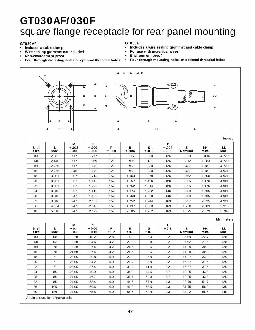
47
GT030AF/030Fsquare flange receptacle for rear panel mounting
All dimensions for reference only.
Inches
ShellSize
LMax.
M+ .016– .000
N+ .000– .006
P± .008
R± .004
S± .012
T+ .004– .000
ZNominal
KKMax.
LLMax.
10SL 2.362 .717 .717 .110 .717 1.000 .126 .220 .894 4.720
14S 2.440 .717 .969 .126 .906 1.181 .126 .312 1.083 4.720
16S 2.756 .717 1.079 .126 .969 1.280 .126 .437 1.181 4.720
16 2.756 .846 1.079 .126 .969 1.280 .126 .437 1.181 4.921
18 3.031 .907 1.213 .157 1.063 1.378 .126 .562 1.300 4.921
20 3.031 .907 1.346 .157 1.157 1.496 .126 .625 1.476 4.921
22 3.031 .907 1.472 .157 1.252 1.614 .126 .625 1.476 4.921
24 3.346 .907 1.610 .157 1.374 1.752 .146 .750 1.705 4.921
28 3.346 .947 1.839 .157 1.563 2.000 .146 .750 1.705 4.921
32 3.346 .947 2.102 .157 1.752 2.244 .169 .937 2.035 4.921
36 4.134 .947 2.346 .157 1.937 2.500 .169 1.250 2.283 5.315
40 5.118 .947 2.579 .157 2.185 2.752 .169 1.375 2.579 5.709
Millimeters
ShellSize
LMax.
M+ 0.4– 0.0
N+ 0.00– 0.15
P± 0.2
R± 0.1
S± 0.3
T+ 0.1– 0.0
ZNominal
KKMax.
LLMax.
10SL 60 18.20 18.2 2.8 18.2 25.4 3.2 5.58 22.7 120
14S 62 18.20 24.6 3.2 23.0 30.0 3.2 7.92 27.5 120
16S 70 18.20 27.4 3.2 24.6 32.5 3.2 11.09 30.0 120
16 70 21.50 27.4 3.2 24.6 32.5 3.2 11.09 30.0 125
18 77 23.05 30.8 4.0 27.0 35.0 3.2 14.27 33.0 125
20 77 23.05 34.2 4.0 29.4 38.0 3.2 15.87 37.5 125
22 77 23.05 37.4 4.0 31.8 41.0 3.2 15.87 37.5 125
24 85 23.05 40.9 4.0 34.9 44.5 3.7 19.05 43.3 125
28 85 24.05 46.7 4.0 39.7 50.8 3.7 19.05 43.3 125
32 85 24.05 53.4 4.0 44.5 57.0 4.3 23.79 51.7 125
36 105 24.05 59.6 4.0 49.2 63.5 4.3 31.75 58.0 135
40 130 24.05 65.5 4.0 55.5 69.9 4.3 34.92 65.5 145
GT030AF• Includes a cable clamp• Wire sealing grommet not included• Non-environment proof• Four through mounting holes or optional threaded holes
GT030F• Includes a wire sealing grommet and cable clamp• For use with individual wires• Environment proof• Four through mounting holes or optional threaded holes
R
R S
S
T
R S N
L
M P
Z KK
LL

48
GT030Gsquare flange receptacle for rear panel mounting• Four through mounting holes or optional threaded holes• With wire sealing grommet for individual wires• Includes backshell for use with heat-shrink tubing• Environment proof
All dimensions for reference only.
Inches
ShellSize
J± .008
K± .020
LMax.
M+ .016– .000
N+ .000– .006
P± .008
R± .004
S± .012
T+ .004– .000
ZMin.
BBMax.
JJ± .008
KK± .008
10SL .138 .461 1.969 .717 .717 .110 .717 1.000 .126 .303 .524 .610 .669
14S .138 .461 1.969 .717 .969 .126 .906 1.181 .126 .417 .669 .752 .791
16S .138 .461 1.969 .717 1.079 .126 .969 1.280 .126 .531 .862 .941 .925
16 .138 .453 2.362 .846 1.079 .126 .969 1.280 .126 .531 .862 .941 .925
18 .138 .453 2.362 .907 1.213 .157 1.063 1.378 .126 .575 .862 .941 1.043
20 .138 .500 2.559 .907 1.346 .157 1.157 1.496 .126 .736 1.031 1.165 1.189
22 .138 .500 2.559 .907 1.472 .157 1.252 1.614 .126 .819 1.031 1.165 1.323
24 .138 .500 2.559 .907 1.610 .157 1.374 1.752 .146 .969 1.358 1.488 1.421
28 .138 .500 2.559 .947 1.839 .157 1.563 2.000 .146 1.063 1.358 1.488 1.630
32 .138 .598 2.756 .947 2.102 .157 1.752 2.244 .169 1.311 1.717 1.882 1.913
36 .138 .598 3.150 .947 2.346 .157 1.937 2.500 .169 1.516 1.717 1.882 2.157
40 .138 .610 3.150 .947 2.579 1.57 2.185 2.752 .169 1.898 2.071 2.276 2.402
Millimeters
ShellSize
J± 0.2
K± 0.5
LMax.
M+ 0.4– 0.0
N+ 0.00– 0.15
P± 0.2
R± 0.1
S± 0.3
T+ 0.1– 0.0
ZMin.
BMax.
JJ± 0.2
KK± 0.2
10SL 3.5 11.7 50 18.20 18.2 2.8 18.2 25.4 3.2 7.7 13.3 15.5 17.0
14S 3.5 11.7 50 18.20 24.6 3.2 23.0 30.0 3.2 10.6 17.0 19.1 20.1
16S 3.5 11.7 50 18.20 27.4 3.2 24.6 32.5 3.2 13.5 21.9 23.9 23.5
16 3.5 11.5 60 21.50 27.4 3.2 24.6 32.5 3.2 13.5 21.9 23.9 23.5
18 3.5 11.5 60 23.05 30.8 4.0 27.0 35.0 3.2 14.6 21.9 23.9 26.5
20 3.5 12.7 65 23.05 34.2 4.0 29.4 38.0 3.2 18.7 26.2 29.6 30.2
22 3.5 12.7 65 23.05 37.4 4.0 31.8 41.0 3.2 20.8 26.2 29.6 33.6
24 3.5 12.7 65 23.05 40.9 4.0 34.9 44.5 3.7 24.6 34.5 37.8 36.1
28 3.5 12.7 65 24.05 46.7 4.0 39.7 50.8 3.7 27.0 34.5 37.8 41.4
32 3.5 15.2 70 24.05 53.4 4.0 44.5 57.0 4.3 33.3 43.6 47.8 48.6
36 3.5 15.2 80 24.05 59.6 4.0 49.2 63.5 4.3 38.5 43.6 47.8 54.8
40 3.5 15.5 80 24.05 65.5 4.0 55.5 69.9 4.3 48.2 52.6 57.8 61.0
R
R S
S
T
N
L
M P
KKJJBBZ
J
K
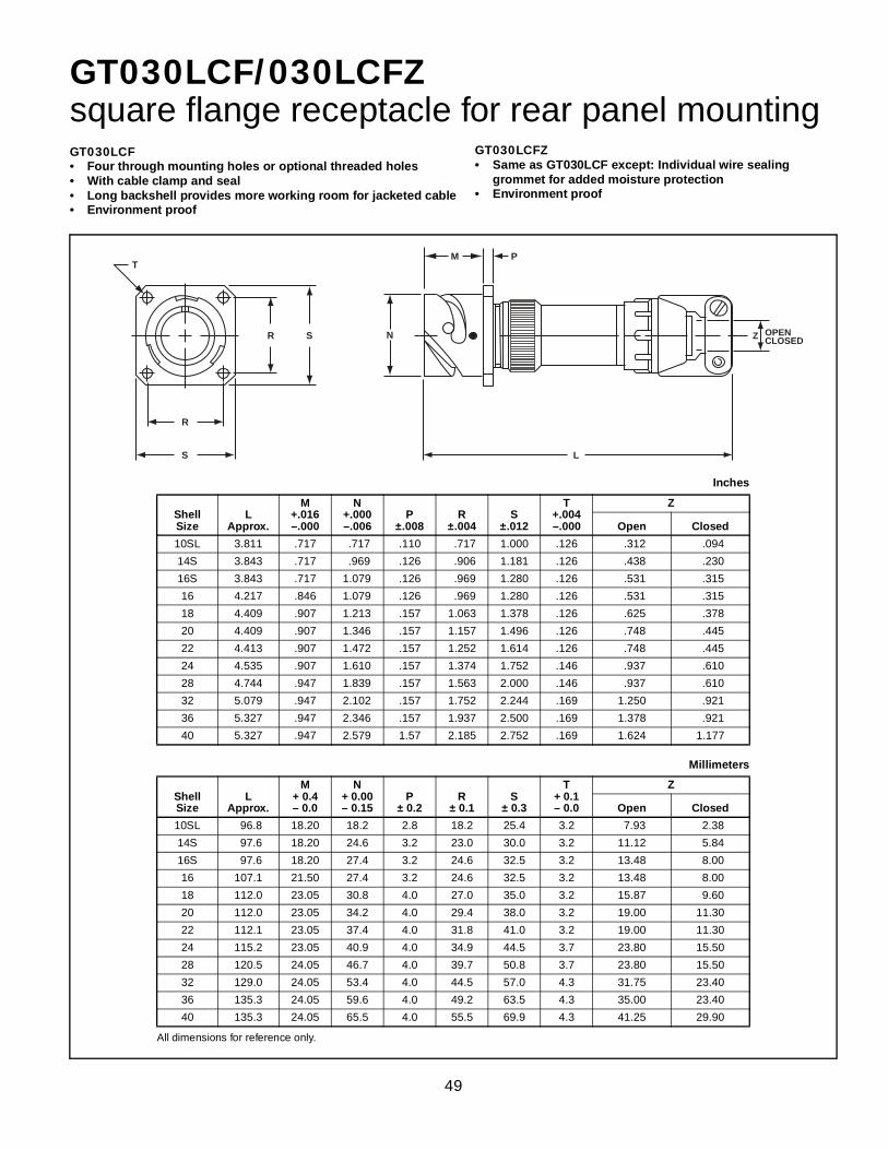
49
GT030LCF/030LCFZsquare flange receptacle for rear panel mounting
All dimensions for reference only.
Inches
ShellSize
LApprox.
M+.016–.000
N+.000–.006
P±.008
R±.004
S±.012
T+.004–.000
Z
Open Closed
10SL 3.811 .717 .717 .110 .717 1.000 .126 .312 .094
14S 3.843 .717 .969 .126 .906 1.181 .126 .438 .230
16S 3.843 .717 1.079 .126 .969 1.280 .126 .531 .315
16 4.217 .846 1.079 .126 .969 1.280 .126 .531 .315
18 4.409 .907 1.213 .157 1.063 1.378 .126 .625 .378
20 4.409 .907 1.346 .157 1.157 1.496 .126 .748 .445
22 4.413 .907 1.472 .157 1.252 1.614 .126 .748 .445
24 4.535 .907 1.610 .157 1.374 1.752 .146 .937 .610
28 4.744 .947 1.839 .157 1.563 2.000 .146 .937 .610
32 5.079 .947 2.102 .157 1.752 2.244 .169 1.250 .921
36 5.327 .947 2.346 .157 1.937 2.500 .169 1.378 .921
40 5.327 .947 2.579 1.57 2.185 2.752 .169 1.624 1.177
Millimeters
ShellSize
LApprox.
M+ 0.4– 0.0
N+ 0.00– 0.15
P± 0.2
R± 0.1
S± 0.3
T+ 0.1– 0.0
Z
Open Closed
10SL 96.8 18.20 18.2 2.8 18.2 25.4 3.2 7.93 2.38
14S 97.6 18.20 24.6 3.2 23.0 30.0 3.2 11.12 5.84
16S 97.6 18.20 27.4 3.2 24.6 32.5 3.2 13.48 8.00
16 107.1 21.50 27.4 3.2 24.6 32.5 3.2 13.48 8.00
18 112.0 23.05 30.8 4.0 27.0 35.0 3.2 15.87 9.60
20 112.0 23.05 34.2 4.0 29.4 38.0 3.2 19.00 11.30
22 112.1 23.05 37.4 4.0 31.8 41.0 3.2 19.00 11.30
24 115.2 23.05 40.9 4.0 34.9 44.5 3.7 23.80 15.50
28 120.5 24.05 46.7 4.0 39.7 50.8 3.7 23.80 15.50
32 129.0 24.05 53.4 4.0 44.5 57.0 4.3 31.75 23.40
36 135.3 24.05 59.6 4.0 49.2 63.5 4.3 35.00 23.40
40 135.3 24.05 65.5 4.0 55.5 69.9 4.3 41.25 29.90
GT030LCFZ• Same as GT030LCF except: Individual wire sealing
grommet for added moisture protection• Environment proof
GT030LCF• Four through mounting holes or optional threaded holes• With cable clamp and seal• Long backshell provides more working room for jacketed cable• Environment proof
R
R S
S
T
N
L
M P
Z OPENCLOSED

50
GT030Rsquare flange receptacle for rear panel mounting• Four through mounting holes or optional threaded holes• With a wire sealing grommet for individual wires• Includes backshell for conduit termination• Environment proof
All dimensions for reference only.
Inches
ShellSize
BThread
Class 2AF
Min.K
Min.L
Max.
M+ .016– .000
N+ .000– .006
P± .008
R± .004
S± .012
T+ .004– .000
10SL .6250-24 UNEF .409 .374 1.969 .717 .717 .110 .717 1.000 .126
14S .7500-20 UNEF .520 .374 1.969 .717 .969 .126 .906 1.181 .126
16S .8750-20 UNEF .638 .374 1.969 .717 1.079 .126 .969 1.280 .126
16 .8750-20 UNEF .638 .374 2.362 .846 1.079 .126 .969 1.280 .126
18 1.0000-20 UNEF .756 .374 2.362 .907 1.213 .157 1.063 1.378 .126
20 1.1875-18 UNEF .867 .374 2.362 .907 1.346 .157 1.157 1.496 .126
22 1.1875-18 UNEF .965 .374 2.362 .907 1.472 .157 1.252 1.614 .126
24 1.4375-18 UNEF 1.094 .374 2.560 .907 1.610 .157 1.374 1.752 .146
28 1.4375-18 UNEF 1.228 .374 2.560 .947 1.839 .157 1.563 2.000 .146
32 1.7500-18 UNS 1.488 .433 2.560 .947 2.102 .157 1.752 2.244 .169
36 2.0000-18 UNS 1.780 .465 3.150 .947 2.346 .157 1.937 2.500 .169
40 2.2500-16 UN 2.016 .465 3.150 .947 2.579 .157 2.185 2.752 .169
Millimeters
ShellSize
FMin.
KMin.
LMax.
M+ 0.4– 0.0
N+ 0.00– 0.15
P± 0.2
R± 0.1
S± 0.3
T+ 0.1– 0.0
10SL 10.4 9.5 50 18.20 18.2 2.8 18.2 25.4 3.2
14S 13.2 9.5 50 18.20 24.6 3.2 23.0 30.0 3.2
16S 16.2 9.5 50 18.20 27.4 3.2 24.6 32.5 3.2
16 16.2 9.5 60 21.50 27.4 3.2 24.6 32.5 3.2
18 19.2 9.5 60 23.05 30.8 4.0 27.0 35.0 3.2
20 22.0 9.5 60 23.05 34.2 4.0 29.4 38.0 3.2
22 24.5 9.5 60 23.05 37.4 4.0 31.8 41.0 3.2
24 27.8 9.5 65 23.05 40.9 4.0 34.9 44.5 3.7
28 31.2 9.5 65 24.05 46.7 4.0 39.7 50.8 3.7
32 37.8 11.0 65 24.05 53.4 4.0 44.5 57.0 4.3
36 45.2 11.8 80 24.05 59.6 4.0 49.2 63.5 4.3
40 51.2 11.8 80 24.05 65.5 4.0 55.5 69.9 4.3
R
R S
S
T
N F
L
K
M P B

51
GT030RVsquare flange receptacle for rear panel mounting• Four through mounting holes or optional threaded holes• With wire sealing grommet for individual wires• Environment proof
All dimensions for reference only.
Inches
ShellSize
LMax.
M+ .016– .000
N+ .000– .006
P± .008
R± .004
S± .012
T+ .004– .000
KKMax.
10SL 1.890 .717 .717 .110 .717 1.000 .126 .787
14S 1.890 .717 .969 .126 .906 1.181 .126 .945
16S 1.890 .717 1.079 .126 .969 1.280 .126 1.024
16 2.205 .846 1.079 .126 .969 1.280 .126 1.024
18 2.244 .907 1.213 .157 1.063 1.378 .126 1.161
20 2.244 .907 1.346 .157 1.157 1.496 .126 1.299
22 2.244 .907 1.472 .157 1.252 1.614 .126 1.417
24 2.244 .907 1.610 .157 1.374 1.752 .146 1.575
28 2.244 .947 1.839 .157 1.563 2.000 .146 1.811
32 2.362 .947 2.102 .157 1.752 2.244 .169 2.028
36 2.362 .947 2.346 .157 1.937 2.500 .169 2.283
40 2.362 .947 2.579 .157 2.185 2.752 .169 2.539
Millimeters
ShellSize
LMax.
M+ 0.4– 0.0
N+ 0.00– 0.15
P± 0.2
R± 0.1
S± 0.3
T+ 0.1– 0.0
KKMax.
10SL 48.0 18.20 18.2 2.8 18.2 25.4 3.2 20.0
14S 48.0 18.20 24.6 3.2 23.0 30.0 3.2 24.0
16S 48.0 18.20 27.4 3.2 24.6 32.5 3.2 26.0
16 56.0 21.50 27.4 3.2 24.6 32.5 3.2 26.0
18 57.0 23.05 30.8 4.0 27.0 35.0 3.2 29.5
20 57.0 23.05 34.2 4.0 29.4 38.0 3.2 33.0
22 57.0 23.05 37.4 4.0 31.8 41.0 3.2 36.0
24 57.0 23.05 40.9 4.0 34.9 44.5 3.7 40.0
28 57.0 24.05 46.7 4.0 39.7 50.8 3.7 46.0
32 60.0 24.05 53.4 4.0 44.5 57.0 4.3 51.5
36 60.0 24.05 59.6 4.0 49.2 63.5 4.3 58.0
40 60.0 24.05 65.5 4.0 55.5 69.9 4.3 64.5
R
R S
S
T
N
M P
L
KK

52
GT06Astraight plug
All dimensions for reference only.
Inches
ShellSize
BThread
Class 2AF
Min.K
Min.L
Max.Q
Max.
10SL .6250-24UNEF .409 .374 1.969 .898
14S .7500-20UNEF .520 .374 1.969 1.150
16S .8750-20UNEF .638 .374 1.969 1.260
16 .8750-20UNEF .638 .374 2.362 1.260
18 1.0000-20UNEF .756 .374 2.362 1.437
20 1.1875-18UNEF .867 .374 2.362 1.571
22 1.1875-18UNEF .965 .374 2.362 1.697
24 1.4375-18UNEF 1.094 .374 2.560 1.835
28 1.4375-18UNEF 1.228 .374 2.560 2.102
32 1.7500-18UNS 1.488 .433 2.560 2.366
36 2.0000-18UNS 1.780 .465 3.150 2.610
40 2.2500-16UN 2.016 .465 3.150 2.850
Millimeters
ShellSize
FMin.
KMin.
LMax.
QMax.
10SL 10.4 9.5 50 22.8
14S 13.2 9.5 50 29.2
16S 16.2 9.5 50 32.0
16 16.2 9.5 60 32.0
18 19.2 9.5 60 36.5
20 22.0 9.5 60 39.9
22 24.5 9.5 60 43.1
24 27.8 9.5 65 46.6
28 31.2 9.5 65 53.4
32 37.8 11.0 65 60.1
36 45.2 11.8 80 66.3
40 51.2 11.8 80 72.4
• Without grommet and cable clamp• If a cable clamp is required, see pages 82 and 84• Non-environment proof
Q
B
F
K
L

53
GT06AF/06Fstraight plug
All dimensions for reference only.
Inches
ShellSize
LMax.
QMax.
ZNominal
KKMax.
LLMax.
10SL 2.165 .898 .220 .894 4.724
14S 2.362 1.150 .312 1.083 4.724
16S 2.756 1.260 .437 1.181 4.724
16 2.756 1.260 .437 1.181 4.921
18 2.953 1.437 .562 1.299 4.921
20 2.953 1.571 .625 1.476 4.921
22 2.953 1.697 .625 1.476 4.921
24 3.543 1.835 .750 1.705 4.921
28 3.543 2.102 .750 1.705 4.921
32 3.543 2.366 .937 2.035 4.921
36 3.937 2.610 1.250 2.283 5.315
40 4.921 2.850 1.375 2.579 5.709
Millimeters
ShellSize
LMax.
QMax.
ZNominal
KKMax.
LLMax.
10SL 55 22.8 5.58 22.7 120
14S 60 29.2 7.92 27.5 120
16S 70 32.0 11.09 30.0 120
16 70 32.0 11.09 30.0 125
18 75 36.5 14.27 33.0 125
20 75 39.9 15.87 37.5 125
22 75 43.1 15.87 37.5 125
24 90 46.6 19.05 43.3 125
28 90 53.4 19.05 43.3 125
32 90 60.1 23.79 51.7 125
36 100 66.3 31.75 58.0 135
40 125 72.4 34.92 65.5 145
GT06AF• With a cable clamp• Wire sealing grommet not supplied• Non-environment proof
GT06F• With a wire sealing grommet and cable clamp• For use with individual wires• Environment proof
Q
Z KK
L
LL

54
GT06CFstraight plug
All dimensions for reference only.
Inches
ShellSize
JApprox.
LApprox.
QMax.
Z
Open Closed
10SL .551 2.752 .898 .312 .094
14S .732 2.898 1.150 .438 .230
16S .732 2.898 1.260 .531 .315
16 .653 3.216 1.260 .531 .315
18 .705 3.307 1.437 .625 .378
20 .705 3.311 1.571 .748 .445
22 .744 3.350 1.697 .748 .445
24 .689 3.484 1.835 .937 .610
28 .921 3.736 2.102 .937 .610
32 1.016 4.142 2.366 1.250 .921
36 1.031 4.390 2.610 1.378 .921
40 1.614 4.640 2.854 1.624 1.177
Millimeters
ShellSize
JApprox.
LApprox.
QMax.
Z
Open Closed
10SL 14.0 69.6 22.8 7.93 2.38
14S 18.6 73.6 29.2 11.12 5.84
16S 18.6 73.6 32.0 13.48 8.00
16 16.6 81.7 32.0 13.48 8.00
18 17.9 84.0 36.5 15.87 9.60
20 17.9 84.1 39.9 19.00 11.30
22 18.9 85.1 43.1 19.00 11.30
24 17.5 88.5 46.6 23.80 15.50
28 23.4 94.9 53.4 23.80 15.50
32 25.8 105.2 60.1 31.75 23.40
36 26.2 111.5 66.3 35.00 23.40
40 41.0 111.5 72.5 41.25 29.90
• With a cable clamp and seal• For use with jacketed cable• Environment proof
Q
Z
J
Cable jacketStrip length
L
OPENCLOSED

55
GT06CFGGstraight plug• With rubber covered coupling nut for extreme shock
applications• The shrouded coupling nut protects the plug from damage• Provides a superior gripping surface• Seals the bayonet ramps
• Includes a backshell• Mates with GT020RFSM (see page 44)• Environment proof
All dimensions for reference only.
Inches
ShellSize
JApprox.
LApprox.
QMax.
SDia.
Z
Open Closed
10SL .551 3.150 1.319 1.122 .312 .094
18 .701 3.346 1.929 1.713 .625 .378
20 .705 3.937 2.028 1.811 .748 .445
22 .705 3.937 2.224 1.988 .748 .445
24 .689 4.016 2.362 2.126 .937 .610
28 .921 4.291 2.638 2.402 .937 .610
32 1.016 5.315 2.992 2.661 1.250 .921
36 1.031 5.039 3.240 2.925 1.378 .921
40 1.614 5.315 3.465 3.150 1.624 1.177
Millimeters
ShellSize
JApprox.
LApprox.
QMax.
SDia.
Z
Open Closed
10SL 14.0 80 33.5 28.5 7.93 2.38
18 17.8 85 49.0 43.5 15.87 9.60
20 17.9 100 51.5 46.0 19.00 11.30
22 17.9 100 56.5 50.5 19.00 11.30
24 17.5 102 60.0 54.0 23.80 15.50
28 23.4 109 67.0 61.0 23.80 15.50
32 25.6 135 76.0 67.6 31.75 23.40
36 26.2 128 82.3 74.3 35.00 23.40
40 41.0 135 88.0 80.0 41.25 29.90
LQ
S Z
J
Cable jacketStrip length
OPENCLOSED

56
GT06Gstraight plug• With a wire sealing grommet• For use with individual wires• Includes a backshell for use with heat-shrink tubing• Environment proof
All dimensions for reference only.
Inches
ShellSize
J± .008
K± .020
LMax.
QMax.
ZMin.
BBMax.
JJ± .008
KK± .008
10SL .138 .461 1.969 .898 .303 .524 .610 .669
14S .138 .461 1.969 1.150 .417 .669 .752 .791
16S .138 .461 1.969 1.260 .531 .862 .941 .925
16 .138 .453 2.362 1.260 .531 .862 .941 .925
18 .138 .453 2.362 1.437 .575 .862 .941 1.043
20 .138 .500 2.559 1.571 .736 1.031 1.165 1.189
22 .138 .500 2.559 1.697 .819 1.031 1.165 1.323
24 .138 .500 2.559 1.835 .969 1.358 1.488 1.421
28 .138 .500 2.559 2.102 1.063 1.358 1.488 1.630
32 .138 .598 2.756 2.366 1.311 1.717 1.882 1.913
36 .138 .598 3.150 2.610 1.516 1.717 1.882 2.157
40 .138 .610 3.150 2.854 1.898 2.071 2.276 2.402
Millimeters
ShellSize
J± 0.2
K± 0.5
LMax.
QMax.
ZMin.
BBMax.
JJ± 0.2
KK± 0.2
10SL 3.5 11.7 50 22.8 7.7 13.3 15.5 17.0
14S 3.5 11.7 50 29.2 10.6 17.0 19.1 20.1
16S 3.5 11.7 50 32.0 13.5 21.9 23.9 23.5
16 3.5 11.5 60 32.0 13.5 21.9 23.9 23.5
18 3.5 11.5 60 36.5 14.6 21.9 23.9 26.5
20 3.5 12.7 65 39.9 18.7 26.2 29.6 30.2
22 3.5 12.7 65 43.1 20.8 26.2 29.6 33.6
24 3.5 12.7 65 46.6 24.6 34.5 37.8 36.1
28 3.5 12.7 65 53.4 27.0 34.5 37.8 41.4
32 3.5 15.2 70 60.1 33.3 43.6 47.8 48.6
36 3.5 15.2 80 66.3 38.5 43.6 47.8 54.8
40 3.5 15.2 80 72.5 48.2 52.6 57.8 61.0
Q
BB JJ KKZ
J
K
L

57
GT06G2straight plug• For use with individual wires and termination of heat shrink tubing• With individual wire sealing grommet• Backshell includes free spinning adapter• Environment proof
All dimensions for reference only.
Inches
ShellSize
CMin.
DMax.
E±.008
LMax.
M±.020
QMax.
R±.007
10SL .303 .524 .610 1.969 .461 .898 .669
14S .417 .669 .752 1.969 .461 1.150 .791
16S .531 .862 .941 1.969 .461 1.299 .925
16 .531 .862 .941 2.362 .453 1.299 .925
18 .637 .862 .941 2.362 .453 1.437 1.043
20 .736 1.031 1.165 2.559 .500 1.571 1.189
22 .877 1.031 1.165 2.559 .500 1.697 1.323
24 .969 1.358 1.488 2.559 .500 1.835 1.421
28 1.094 1.358 1.488 2.559 .500 2.102 1.630
32 1.392 1.717 1.882 2.756 .598 2.366 1.913
36 1.539 1.717 1.882 3.150 .598 2.610 2.157
40 1.898 2.071 2.276 3.150 .610 2.850 2.402
Millimeters
ShellSize
CMin.
DMax.
E±.008
LMax.
M±.020
QMax.
R±.007
10SL 7.7 13.3 15.5 50.0 11.7 22.8 17.0
14S 10.6 17.0 19.1 50.0 11.7 29.2 20.1
16S 13.5 21.9 23.9 50.0 11.7 32.0 23.5
16 13.5 21.9 23.9 60.0 11.5 32.0 23.5
18 16.2 21.9 23.9 60.0 11.5 36.5 26.5
20 18.7 26.2 29.6 65.0 12.7 39.9 30.2
22 22.3 26.2 29.6 65.0 12.7 43.1 33.6
24 24.6 34.5 37.8 65.0 12.7 46.6 36.0
28 27.8 34.5 37.8 65.0 12.7 53.4 41.4
32 35.4 43.6 47.8 70.0 15.2 60.1 48.6
36 39.1 43.6 47.8 80.0 15.2 66.3 54.8
40 48.2 52.6 57.8 80.0 15.5 72.5 61.0
Q
E
R
DC
L
.138±.008
M

58
GT06LCstraight plug
All dimensions for reference only. * For example, typical part number would be:GTC06LC28-8PA59
Inches
ShellSize
LRef.
QMax.
Cable Range
AXX Part No. Suffix* Min. Max.
10SL 3.000 .898 A16 .250 .375
14S 3.000 1.150 A54 .375 .500
16S 3.000 1.260 A10 .500 .625
16 3.250 1.260 A12 .625 .750
18 3.250 1.437 A42 .750 .875
20 3.250 1.571 A11 .875 1.000
22 3.250 1.697 A55 1.000 1.125
24 3.250 1.835 A14 1.125 1.250
28 3.600 2.102 A56 1.250 1.375
32 3.600 2.366 A74 1.375 1.500
36 3.600 2.610 A57 1.500 1.625
40 3.600 2.854 A58 1.625 1.750
Millimeters
ShellSize
LRef.
QMax.
Cable Range
AXX Part No. Suffix* Min. Max.
10SL 76.2 22.8 A16 6.3 9.5
14S 76.2 29.2 A54 9.5 12.7
16S 76.2 32.0 A10 12.7 15.8
16 82.5 32.0 A12 15.8 19.0
18 82.5 36.4 A42 19.0 22.2
20 82.5 39.9 A11 22.2 25.4
22 82.5 43.1 A55 25.4 28.5
24 82.5 46.6 A14 28.5 31.7
28 91.4 53.3 A56 31.7 34.9
32 91.4 60.0 A74 34.9 38.1
36 91.4 66.2 A57 38.1 41.2
40 91.4 72.4 A58 41.2 44.4
• Includes a backshell with a basket weave strain relief cord grip• Environment proof
Q
Cable RangeMin./Max.
L

59
GT06LCF/06LCFZstraight plug
All dimensions for reference only.
Inches
ShellSize
LApprox.
QMax.
Z
Open Closed
10SL 3.811 .898 .312 .094
14S 3.843 1.150 .438 .230
16S 3.843 1.260 .531 .315
16 4.217 1.260 .531 .315
18 4.409 1.437 .625 .378
20 4.409 1.571 .748 .445
22 4.413 1.697 .748 .445
24 4.535 1.835 .937 .610
28 4.756 2.102 .937 .610
32 5.079 2.366 1.250 .921
36 5.327 2.610 1.378 .921
40 5.327 2.854 1.624 1.177
Millimeters
ShellSize
LApprox.
QMax.
Z
Open Closed
10SL 96.8 22.8 7.93 2.38
14S 97.6 29.2 11.12 5.84
16S 97.6 32.0 13.48 8.00
16 107.1 32.0 13.48 8.00
18 112.0 36.5 15.87 9.60
20 112.0 39.9 19.00 11.30
22 112.1 43.1 19.00 11.30
24 115.2 46.6 23.80 15.50
28 120.8 53.4 23.80 15.50
32 129.0 60.1 31.75 23.40
36 135.3 66.3 35.00 23.40
40 135.3 72.5 41.25 29.90
GT06LCF• With cable clamp and seal• Long backshell provides more working room
for jacketed cable• Environment proof
GT06LCFZ• Same as GT06LCF except: Individual wire sealing
grommet for added moisture protection• Environment proof
GT06LCF• With cable clamp and seal• Long backshell provides more working room
for jacketed cable• Environment proof
Q
L
Z OPENCLOSED

60
GT06LTstraight plug
All dimensions for reference only.
Inches
ShellSize
LMax.
QMax.
10SL
Dependent on Conduit and Shell Combination
Consult Amphenol,Sidney, NY for further information
.898
14S 1.150
16S 1.299
16 1.299
18 1.437
20 1.571
22 1.697
24 1.835
28 2.102
32 2.366
36 2.610
40 2.850
Millimeters
ShellSize
LMax.
QMax.
10SL
Dependent on Conduit and Shell Combination
Consult Amphenol,Sidney, NY for further information
22.81
14S 29.21
16S 32.99
16 32.99
18 36.50
20 39.90
22 43.10
24 46.61
28 53.39
32 60.10
36 66.29
40 72.39
Inches
CConduit
Size
3/8
1/2
3/4
1
1-1/4
1-1/2
2
• For termination of metallic core conduit• With individual wire sealing grommet• Environment proof
L
Q
CDIA. OF CONDUIT

61
GT06PFCstraight plug
All dimensions for reference only.
Inches
ShellSize
CConduit Size
LMax.
QMax.
10SL
Wide Variety of Sizes
Consult Amphenol, Sidney, NY for further information
Dependent on Conduit and Shell Combination
Consult Amphenol,Sidney, NY for further information
.898
14S 1.150
16S 1.299
16 1.299
18 1.437
20 1.571
22 1.697
24 1.835
28 2.102
32 2.366
36 2.610
40 2.850
Millimeters
ShellSize
CConduit Size
LMax.
QMax.
10SL
Wide Variety of Sizes
Consult Amphenol, Sidney, NY for further information
Dependent on Conduit and Shell Combination
Consult Amphenol,Sidney, NY for further information
22.81
14S 29.21
16S 32.99
16 32.99
18 36.50
20 39.90
22 43.10
24 46.61
28 53.39
32 60.10
36 66.29
40 72.39
• For termination of plastic flexible corrugated conduit• With individual wire sealing grommet• Environment proof
Q
L
CDIA. OF CONDUIT

62
GT06PGstraight plug• Long adapter with internal PG thread• With wire sealing grommet• Environment proof
All dimensions for reference only.Additional shell size/PG thread combinations available
Inches
ShellSize
PG*Thread
LRef.
QMax.
10SL 7 2.873 .898
14S 9 2.904 1.150
16S 11 2.904 1.299
16 11 3.291 1.299
18 13.5 3.406 1.437
20 16 3.391 1.571
22 21 3.395 1.697
24 21 3.470 1.835
28 29 3.604 2.102
32 36 3.751 2.366
36 42 3.795 2.610
40 48 3.795 2.850
Millimeters
ShellSize
PG*Thread
LRef.
QMax.
10SL 7 73.0 22.8
14S 9 73.8 29.2
16S 11 73.8 32.0
16 11 83.6 32.0
18 13.5 86.5 36.5
20 16 86.1 39.9
22 21 86.2 43.1
24 21 88.1 46.6
28 29 91.5 53.4
32 36 95.3 60.1
36 42 96.4 66.3
40 48 96.4 72.5
Q L
PG THREAD

63
GT06PP/064PPpanel plug
All dimensions for reference only.
Inches
ShellSize
LApprox.
QMax.
Q1
Max.P
± .008R
± .004S
± .012
T+ .004– .000
10SL 1.087 .898 .953 .110 .717 1.000 .126
14S 1.091 1.150 1.208 .126 .906 1.181 .126
16S 1.091 1.260 1.319 .126 .969 1.280 .126
16 1.469 1.260 1.319 .126 .969 1.280 .126
18 1.500 1.437 1.510 .157 1.063 1.378 .126
20 1.500 1.571 1.660 .157 1.157 1.496 .126
22 1.500 1.697 1.770 .157 1.252 1.614 .126
24 1.598 1.835 1.910 .157 1.374 1.752 .146
28 1.626 2.102 2.085 .157 1.563 2.000 .146
32 1.764 2.366 2.440 .157 1.752 2.244 .169
36 1.764 2.610 2.660 .157 1.937 2.500 .169
40 1.764 2.850 2.910 .157 2.185 2.752 .169
ShellSize
LApprox.
QMax.
Q1
Max.P
± 0.2R
± 0.1S
± 0.3
T+ 0.1– 0.0
10SL 27.6 22.8 24.2 2.8 18.2 25.4 3.2
14S 27.7 29.2 30.6 3.2 23.0 30.0 3.2
16S 27.7 32.0 33.5 3.2 24.6 32.5 3.2
16 37.3 32.0 33.5 3.2 24.6 32.5 3.2
18 38.1 36.5 38.3 4.0 27.0 35.0 3.2
20 38.1 39.9 42.1 4.0 29.4 38.0 3.2
22 38.1 43.1 44.9 4.0 31.8 41.0 3.2
24 40.6 46.6 48.5 4.0 34.9 44.5 3.7
28 41.3 53.4 52.9 4.0 39.7 50.8 3.7
32 44.8 60.1 61.9 4.0 44.5 57.0 4.3
36 44.8 66.3 67.5 4.0 49.2 63.5 4.3
40 44.8 72.4 73.9 4.0 55.5 69.9 4.3
GT06PP• Square flange mounting with four through holes• Environment proof with proper panel sealing gasket
(see page 79)
GT064PP• Square flange mounting with four through holes• Environment proof with proper panel sealing gasket
(see page 79)• Includes a heavy duty coupling nut
S
R
S R
T
GT06PP
P
Q
L
S R
S
R
T
GT064PP
L
P
Q1

64
GT06Rstraight plug• With a wire sealing grommet• Includes a backshell for conduit termination• Environment proof
All dimensions for reference only.
Inches
ShellSize
BThread
Class 2AF
Min.K
Min.L
Max.Q
Max.
10SL .6250-24UNEF .409 .374 1.969 .898
14S .7500-20UNEF .520 .374 1.969 1.150
16S .8750-20UNEF .638 .374 1.969 1.260
16 .8750-20UNEF .638 .374 2.362 1.260
18 1.0000-20UNEF .756 .374 2.362 1.437
20 1.1875-18UNEF .867 .374 2.362 1.571
22 1.1875-18UNEF .965 .374 2.362 1.697
24 1.4375-18UNEF 1.094 .374 2.560 1.835
28 1.4375-18UNEF 1.228 .374 2.560 2.102
32 1.7500-18UNS 1.488 .433 2.560 2.366
36 2.0000-18UNS 1.780 .465 3.150 2.610
40 2.2500-16UN 2.016 .465 3.150 2.850
Millimeters
ShellSize
FMin.
KMin.
LMax.
QMax.
10SL 10.4 9.5 50 22.8
14S 13.2 9.5 50 29.2
16S 16.2 9.5 50 32.0
16 16.2 9.5 60 32.0
18 19.2 9.5 60 36.5
20 22.0 9.5 60 39.9
22 24.5 9.5 60 43.1
24 27.8 9.5 65 46.6
28 31.2 9.5 65 53.4
32 37.8 11.0 65 60.1
36 45.2 11.8 80 66.3
40 51.2 11.8 80 72.4
Q
B
F
K
L

65
GT06RVstraight plug
All dimensions for reference only.
Inches
ShellSize
LMax.
QMax.
KKMax.
10SL 1.417 .898 .787
14S 1.437 1.150 .945
16S 1.437 1.260 1.024
16 1.929 1.260 1.024
18 1.929 1.437 1.161
20 1.969 1.571 1.299
22 1.969 1.697 1.417
24 2.008 1.835 1.543
28 2.008 2.102 1.811
32 2.087 2.366 2.028
36 2.106 2.610 2.283
40 2.126 2.850 2.539
Millimeters
ShellSize
LMax.
QMax.
KKMax.
10SL 36.0 22.8 20.0
14S 36.5 29.2 24.0
16S 36.5 32.0 26.0
16 49.0 32.0 26.0
18 49.0 36.5 29.5
20 50.0 39.9 33.0
22 50.0 43.1 36.0
24 51.0 46.6 40.0
28 51.0 53.4 46.0
32 53.0 60.1 51.5
36 53.5 66.3 58.0
40 54.0 72.4 64.5
• With a wire sealing grommet• For use with individual wires• Environment proof
KK
Q L

66
GT06SBstraight plug• For termination of shielded braid and heatshrink tube or boot.• With individual wire sealing grommet• Environment proof
All dimensions for reference only.
Inches
ShellSize
CMin.
DMax.
EMax.
FRef.
LRef.
QMax.
RMax.
10SL .303 .641 .775 .625 2.034 .898 .786
14S .417 .786 .873 .750 2.049 1.150 .944
16S .531 .905 1.025 .875 2.049 1.299 1.023
16 .531 .905 1.025 .875 2.505 1.299 1.023
18 .637 .965 1.147 1.000 2.552 1.437 1.160
20 .736 1.122 1.305 1.125 2.552 1.571 1.296
22 .819 1.196 1.373 1.250 2.418 1.697 1.416
24 .981 1.364 1.521 1.375 2.632 1.835 1.562
28 1.067 1.476 1.657 1.500 2.566 2.102 1.806
32 1.311 1.732 1.927 1.750 2.628 2.366 2.027
36 1.631 2.007 2.207 2.062 2.676 2.610 2.281
40 1.882 2.283 2.486 2.312 2.628 2.850 2.538
Millimeters
ShellSize
CMin.
DMax.
EMax.
FRef.
LRef.
QMax.
RMax.
10SL 7.7 16.3 19.7 15.9 51.7 22.8 20.0
14S 10.6 20.0 22.2 19.1 52.0 29.2 24.0
16S 13.5 23.0 26.0 22.2 52.0 32.0 26.0
16 13.5 23.0 26.0 22.2 63.6 32.0 26.0
18 16.2 24.5 29.1 25.4 64.8 36.5 29.5
20 18.7 28.5 33.1 28.6 64.8 39.9 32.9
22 20.8 30.4 34.9 31.8 61.4 43.1 36.0
24 24.9 34.6 38.6 34.9 66.8 46.6 39.7
28 27.1 37.5 42.5 38.1 65.2 53.4 45.9
32 33.3 44.0 48.9 44.5 66.8 60.1 51.5
36 41.4 51.0 56.1 52.4 68.0 66.3 57.9
40 47.8 58.0 63.1 58.7 66.8 72.5 64.5
Q
ER
D
C
L
F
.138 REF

67
GT06SBTstraight plug• For termination of shielded braid and heatshrink tube or boot• With wire sealing grommet• Environment proof
All dimensions for reference only.
Inches
ShellSize
CMin.
DMax.
EMax.
FRef.
LRef.
QMax.
RMax.
10SL .303 .641 .775 .437 2.401 .898 .786
14S .417 .768 .873 .563 2.520 1.150 .944
16S .531 .905 1.025 .626 2.756 1.299 1.023
16 .531 .905 1.025 .626 3.150 1.299 1.023
18 .637 .965 1.147 .752 3.150 1.437 1.160
20 .736 1.122 1.305 .878 3.150 1.571 1.296
22 .819 1.196 1.373 1.000 3.150 1.697 1.416
24 .981 1.364 1.521 1.126 3.150 1.835 1.562
28 1.067 1.476 1.657 1.252 3.150 2.102 1.806
32 1.311 1.732 1.927 1.252 3.150 2.366 2.027
36 1.631 2.007 2.207 1.752 3.350 2.610 2.281
40 1.882 2.283 2.486 2.000 3.350 2.850 2.538
Millimeters
ShellSize
CMin.
DMax.
EMax.
FRef.
LRef.
QMax.
RMax.
10SL 7.7 16.3 19.7 11.1 61.0 22.8 20.0
14S 10.6 20.0 22.2 14.3 64.0 29.2 24.0
16S 13.5 23.0 26.0 15.9 71.0 32.0 26.0
16 13.5 23.0 26.0 15.9 80.0 32.0 26.0
18 16.2 24.5 29.1 19.1 80.0 36.5 29.5
20 18.7 28.5 33.1 22.3 80.0 39.9 32.9
22 20.8 30.4 34.9 25.4 80.0 43.1 36.0
24 24.9 34.6 38.6 28.6 80.0 46.6 39.7
28 27.1 37.5 42.5 31.8 80.0 53.4 45.9
32 33.3 44.0 48.9 31.8 80.0 60.1 51.5
36 41.4 51.0 56.1 44.5 85.1 66.3 57.9
40 47.8 58.0 63.1 50.8 85.1 72.5 64.5
Q
ER
D
C
L
F
.138 REF

68
GT065SL(*)straight plug
All dimensions for reference only. * Add suffix 1 or 2 for desired cable range.
Inches
ShellSize
LRef.
QMax.
Cable Range
(1)* (2)*
10SL 3.516 1.007 .11–.26 .07–.12
14S 3.628 1.259 .15–.32 .07–.24
16S 3.808 1.410 .19–.39 .11–.28
16 4.355 1.410 .19–.39 .11–.28
18 4.249 1.547 .23–.47 .19–.35
20 4.255 1.681 .39–.56 .27–.47
22 4.329 1.847 .51–.71 .35–.63
24 4.816 1.965 .51–.71 .35–.63
28 4.817 2.222 .70–.98 .51–.79
32 4.817 2.482 .86–1.26 .78–1.02
36 5.048 2.721 1.26–1.50 .98–1.22
40 4.978 2.953 1.45–1.75 1.14–1.38
Millimeters
ShellSize
LRef.
QMax.
Cable Range
(1)* (2)*
10SL 89.3 25.5 2.7–6.6 1.7–3.0
14S 92.1 31.9 3.8–8.1 1.7–6.0
16S 96.7 35.8 4.8–9.9 2.7–7.1
16 110.6 35.8 4.8–9.9 2.7–7.1
18 107.9 39.2 5.8–11.9 4.8–8.8
20 108.0 42.6 9.9–14.2 6.8–11.9
22 109.9 46.9 12.9–18.0 8.8–16.0
24 122.3 49.9 12.9–18.0 8.8–16.0
28 122.3 56.4 17.7–24.8 12.9–20.0
32 122.3 63.0 21.8–32.0 19.8–25.9
36 128.2 69.1 32.0–38.1 24.8–30.9
40 126.4 75.0 36.8–44.4 28.9–35.05
• Includes a long heavy duty coupling nut• Includes a liquid tight strain relief to grip and seal jacketed cable• Environment proof
Q
Cable Range*
L

69
GT07Rjam nut receptacle• For rear panel single hole mounting• Panel seal O-ring included• Environment proof
All dimensions for reference only.
Inches
ShellSize
BThread
Class 2AG
± .012
JWall Thickness M
± .012
N+ .000– .006
P± .007
R± .016
S± .012Min. Max.
10SL .8750-20 UNEF .441 .094 .205 .965 .717 .157 1.062 1.252
14S 1.1250-18 UNEF .575 .094 .295 1.055 .969 .189 1.312 1.626
16S 1.2500-18 UNEF .618 .094 .295 1.055 1.079 .189 1.500 1.748
16 1.2500-18 UNEF .618 .094 .295 1.264 1.079 .189 1.500 1.748
18 1.3750-18 UNEF .661 .094 .354 1.327 1.213 .189 1.562 1.875
20 1.5000-18 UNEF .709 .094 .358 1.327 1.346 .189 1.750 2.000
22 1.6250-18 UNEF .795 .094 .358 1.327 1.472 .189 2.000 2.134
24 1.7500-18 UNEF .795 .094 .358 1.327 1.610 .189 2.000 2.252
28 2.0000-18 UNS .886 .094 .394 1.386 1.839 .220 2.188 2.500
32 2.2500-16 UN .972 .094 .394 1.386 2.102 .220 2.438 2.748
36 2.5000-16 UN 1.059 .094 .327 1.386 2.346 .220 2.812 3.000
40 2.7500-16 UN 1.165 .094 .327 1.386 2.579 .220 2.953 3.248
Millimeters
ShellSize
G± 0.3
JWall Thickness M
± 0.3
N+ 0.00– 0.15
P± 0.2
R± 0.4
S± 0.3Min. Max.
10SL 11.2 2.4 5.2 24.5 18.2 4.0 27 31.8
14S 14.6 2.4 7.5 26.8 24.6 4.8 33 41.3
16S 15.7 2.4 7.5 26.8 27.4 4.8 38 44.4
16 15.7 2.4 7.5 32.1 27.4 4.8 38 44.4
18 16.8 2.4 9.0 33.7 30.8 4.8 40 47.6
20 18.0 2.4 9.1 33.7 34.2 4.8 44 50.8
22 20.2 2.4 9.1 33.7 37.4 4.8 51 54.2
24 20.2 2.4 9.1 33.7 40.9 4.8 51 57.2
28 22.5 2.4 10.0 35.2 46.7 5.6 56 63.5
32 24.7 2.4 10.0 35.2 53.4 5.6 62 69.8
36 26.9 2.4 8.3 35.2 59.6 5.6 71 76.2
40 29.6 2.4 8.3 35.2 65.5 5.6 75 82.5
G
S
S
G
R
N
M
P
BO-Ring
J

70
GT070jam nut receptacle• For rear panel single hole mounting• Threaded rear for accessories• Environment proof
All dimensions for reference only.
Inches
ShellSize
BThread
Class 2AG
± .012
JWall Thickness L
± .010M
± .012
N+ .000– .006
P± .007
R± .016
S± .012
BBThread
Class 2AMin. Max.
10SL .8750-20 UNEF .441 .094 .205 1.425 .965 .717 .157 1.062 1.252 .6250-24 UNEF
14S 1.1250-18 UNEF .575 .094 .295 1.531 1.055 .969 .189 1.312 1.626 .7500-20 UNEF
16S 1.2500-18 UNEF .618 .094 .295 1.531 1.055 1.079 .189 1.500 1.748 .8750-20 UNEF
16 1.2500-18 UNEF .618 .094 .295 1.909 1.264 1.079 .189 1.500 1.748 .8750-20 UNEF
18 1.3750-18 UNEF .661 .094 .354 1.941 1.327 1.213 .189 1.562 1.875 1.0000-20 UNEF
20 1.5000-18 UNEF .709 .094 .358 1.941 1.327 1.346 .189 1.750 2.000 1.1250-18 UNEF
22 1.6250-18 UNEF .795 .094 .358 1.941 1.327 1.472 .189 2.000 2.134 1.2500-18 UNEF
24 1.7500-18 UNEF .795 .094 .358 1.953 1.327 1.610 .189 2.000 2.252 1.3750-18 UNEF
28 2.0000-18 UNS .886 .094 .394 2.043 1.386 1.839 .220 2.188 2.500 1.6250-18 UNEF
32 2.2500-16 UN .972 .094 .394 2.043 1.386 2.102 .220 2.438 2.748 1.8750-16 UN
36 2.5000-16 UN 1.059 .094 .327 2.043 1.386 2.346 .220 2.812 3.000 2.0625-16 UN
40 2.7500-16 UN 1.165 .094 .327 2.043 1.386 2.579 .220 2.953 3.248 2.3125-16 UN
Millimeters
ShellSize
G± 0.3
JWall Thickness L
± 0.3M
± 0.3
N+ 0.00– 0.15
P± 0.2
R± 0.4
S± 0.3Min. Max.
10SL 11.2 2.4 5.2 36.2 24.5 18.2 4.0 27 31.8
14S 14.6 2.4 7.5 38.9 26.8 24.6 4.8 33 41.3
16S 15.7 2.4 7.5 38.9 26.8 27.4 4.8 38 44.4
16 15.7 2.4 7.5 48.5 32.1 27.4 4.8 38 44.4
18 16.8 2.4 9.0 49.3 33.7 30.8 4.8 40 47.6
20 18.0 2.4 9.1 49.3 33.7 34.2 4.8 44 50.8
22 20.2 2.4 9.1 49.3 33.7 37.4 4.8 51 54.2
24 20.2 2.4 9.1 49.6 33.7 40.9 4.8 51 57.2
28 22.5 2.4 10.0 51.9 35.2 46.7 5.6 56 63.5
32 24.7 2.4 10.0 51.9 35.2 53.4 5.6 62 69.8
36 26.9 2.4 8.3 51.9 35.2 59.6 5.6 71 76.2
40 29.6 2.4 8.3 51.9 35.2 65.5 5.6 75 82.5
N
M
P
BO-Ring
BB
L
JG
S
S
G
R

71
GT08A90° angle plug
All dimensions for reference only.
Inches
ShellSize
BThread
Class 2AF
Max.J
Min.K
Max.L
Max.Q
Max.
10SL .6250-24UNEF .337 .370 1.181 1.772 .898
14S .7500-20UNEF .462 .370 1.181 1.850 1.150
16S .8750-20UNEF .587 .370 1.181 1.890 1.299
16 .8750-20UNEF .587 .370 1.181 2.244 1.299
18 1.0000-20UNEF .685 .370 1.378 2.283 1.437
20 1.1875-18UNEF .810 .370 1.378 2.402 1.571
22 1.1875-18UNEF .915 .370 1.378 2.402 1.697
24 1.4375-18UNEF 1.025 .370 1.575 2.598 1.835
28 1.4375-18UNEF 1.139 .370 1.575 2.598 2.102
32 1.7500-18UNS 1.447 .433 1.772 2.835 2.366
36 2.0000-18UNS 1.687 .496 1.969 2.953 2.610
40 2.2500-16UN 1.923 .496 2.165 3.071 2.850
Millimeters
ShellSize
FMax.
JMin.
KMax.
LMax.
QMax.
10SL 8.5 9.4 30 45 22.8
14S 11.7 9.4 30 47 29.2
16S 14.9 9.4 30 48 33.0
16 14.9 9.4 30 57 33.0
18 17.4 9.4 35 58 36.5
20 20.5 9.4 35 61 39.9
22 23.2 9.4 35 61 43.1
24 26.0 9.4 40 66 46.6
28 28.9 9.4 40 66 53.4
32 36.7 11.0 45 72 60.1
36 42.8 12.6 50 75 66.3
40 48.8 12.6 55 78 72.4
• Without a wire sealing grommet or clamp• Non-environment proof• If a cable clamp is required, see pages 82 and 84
Q
K
J
L
F
B

72
GT08AF/08F90° angle plug
GT08F• With a wire sealing grommet and cable clamp• For use with individual wires• Environment proof
GT08AF• With a cable clamp• Wire sealing grommet not included• Non-environment proof
All dimensions for reference only.
Inches
ShellSize
KMax.
LMax.
QMax.
ZMax.
KKMax.
LLMax.
10SL 1.654 1.772 .898 .220 .894 3.937
14S 1.654 1.850 1.150 .312 1.083 3.937
16S 1.772 1.890 1.299 .437 1.181 3.937
16 1.772 2.244 1.299 .437 1.181 3.937
18 2.087 2.283 1.437 .562 1.299 3.937
20 2.087 2.402 1.571 .625 1.476 3.937
22 2.087 2.402 1.697 .625 1.476 3.937
24 2.283 2.598 1.835 .750 1.705 3.937
28 2.283 2.598 2.102 .750 1.705 3.937
32 2.598 2.835 2.366 .937 2.061 4.331
36 2.717 2.953 2.610 1.250 2.283 4.331
40 3.740 3.071 2.850 1.375 2.579 5.512
Millimeters
ShellSize
KMax.
LMax.
QMax.
ZMax.
KKMax.
LLMax.
10SL 42 45 22.8 5.58 22.7 100
14S 42 47 29.2 7.92 27.5 100
16S 45 48 33.0 11.09 30.0 100
16 45 57 33.0 11.09 30.0 100
18 53 58 36.5 14.27 33.0 100
20 53 61 39.9 15.87 37.5 100
22 53 61 43.1 15.87 37.5 100
24 58 66 46.6 19.05 43.3 100
28 58 66 53.4 19.05 43.3 100
32 66 72 60.1 23.79 51.7 110
36 69 75 66.3 31.75 58.0 110
40 95 78 72.4 34.92 65.5 140
Q L
Z KK
K
LL

73
GT08CFGG90° angle plug• Rubber covered coupling nut provides superior gripping surface
and seals beyond ramps• Includes clamp to grip and seal jacketed cable• Mates with GT020RFSM (see page 44)• Environment proof
All dimensions for reference only.* 14s, 16s and 16 shell sizes are available upon request.
Inches
ShellSize*
KMax.
LMax.
QDia.
SDia.
Z KK± .008Open Closed
10SL 2.402 1.929 1.319 1.122 .312 .094 .890
18 2.677 2.520 1.929 1.713 .625 .378 1.220
20 2.677 2.638 2.028 1.811 .748 .445 1.469
22 2.677 2.638 2.205 1.988 .748 .445 1.469
24 2.992 2.874 2.362 2.126 .937 .610 1.654
28 2.992 2.874 2.638 2.402 .937 .610 1.654
32 3.425 3.071 2.992 2.661 1.250 .921 2.126
36 3.858 3.189 3.240 2.925 1.378 .921 2.248
40 4.055 3.307 3.465 3.150 1.624 1.177 2.500
Millimeters
ShellSize*
KMax.
LMax.
QDia.
SDia.
Z KK± 0.2Open Closed
10SL 61 49 33.5 28.5 7.93 2.38 22.6
18 68 64 49.0 43.5 15.87 9.60 31.0
20 68 67 51.5 46.0 19.00 11.30 37.3
22 68 67 56.0 50.5 19.00 11.30 37.3
24 76 73 60.0 54.0 23.80 15.50 42.0
28 76 73 67.0 61.0 23.80 15.50 42.0
32 87 78 76.0 67.6 31.75 23.40 54.0
36 98 81 82.3 74.3 35.00 23.40 57.1
40 103 84 88.0 80.0 41.25 29.90 63.5
Z OPENCLOSEDKK
Q
S
K
L

74
GT08LT90° angle plug
All dimensions for reference only.
Inches
ShellSize
KMax.
LMax.
QMax.
10SL
Dependent on Conduit and Shell Combination
Consult Amphenol,Sidney, NY for further information
1.772 .898
14S 1.850 1.150
16S 1.890 1.299
16 2.244 1.299
18 2.283 1.437
20 2.402 1.571
22 2.402 1.697
24 2.598 1.835
28 2.598 2.102
32 2.835 2.366
36 2.953 2.610
40 3.071 2.850
Millimeters
ShellSize
KMax.
LMax.
QMax.
10SL
Dependent on Conduit and Shell Combination
Consult Amphenol,Sidney, NY for further information
45.01 22.81
14S 46.99 29.21
16S 48.01 32.99
16 57.00 32.99
18 57.99 36.50
20 61.01 39.90
22 61.01 43.10
24 65.99 46.61
28 65.99 53.39
32 72.01 60.10
36 75.01 66.29
40 78.00 72.39
• For termination of metallic core conduit• With individual wire sealing grommet• Environment proof
Inches
CConduit
Size
3/8
1/2
3/4
1
1-1/4
1-1/2
2
Millimeters
CConduit
Size
9.53
12.70
19.05
25.40
31.75
38.10
50.80
Q L
K
C DIA. OF CONDUIT

75
Q L
CDIA. OFCONDUIT
K
GT08PFC90° angle plug
All dimensions for reference only.
Inches
ShellSize
CConduit Size
KMax.
LMax.
QMax.
10SL
Wide Variety of Sizes
Consult Amphenol, Sidney, NY for further information
Dependent on Conduit and Shell Combination
Consult Amphenol,Sidney, NY for further information
1.772 .898
14S 1.850 1.150
16S 1.890 1.299
16 2.244 1.299
18 2.283 1.437
20 2.402 1.571
22 2.402 1.697
24 2.598 1.835
28 2.598 2.102
32 2.835 2.366
36 2.953 2.610
40 3.071 2.850
Millimeters
ShellSize
CConduit Size
KMax.
LMax.
QMax.
10SL
Wide Variety of Sizes
Consult Amphenol, Sidney, NY for further information
Dependent on Conduit and Shell Combination
Consult Amphenol,Sidney, NY for further information
45.01 22.81
14S 46.99 29.21
16S 48.01 32.99
16 57.00 32.99
18 57.99 36.50
20 61.01 39.90
22 61.01 43.10
24 65.99 46.61
28 65.99 53.39
32 72.01 60.10
36 75.01 66.29
40 78.00 72.39
• For termination of plastic flexible corrugated conduit• With individual wire sealing grommet• Environment proof

76
GT08R90° angle plug
All dimensions for reference only.
Inches
ShellSize
BThread
Class 2AF
Max.J
Min.K
Max.L
Max.Q
Max.
10SL .6250-24UNEF .337 .370 1.181 1.772 .898
14S .7500-20UNEF .462 .370 1.181 1.850 1.150
16S .8750-20UNEF .587 .370 1.181 1.890 1.299
16 .8750-20UNEF .587 .370 1.181 2.244 1.299
18 1.0000-20UNEF .685 .370 1.378 2.283 1.437
20 1.1875-18UNEF .810 .370 1.378 2.402 1.571
22 1.1875-18UNEF .915 .370 1.378 2.402 1.697
24 1.4375-18UNEF 1.025 .370 1.575 2.598 1.835
28 1.4375-18UNEF 1.139 .370 1.575 2.598 2.102
32 1.7500-18UNS 1.447 .433 1.772 2.835 2.366
36 2.0000-18UNS 1.687 .496 1.969 2.953 2.610
40 2.2500-16UN 1.923 .496 2.165 3.071 2.850
Millimeters
ShellSize
FMax.
JMin.
KMax.
LMax.
QMax.
10SL 8.5 9.4 30 45 22.8
14S 11.7 9.4 30 47 29.2
16S 14.9 9.4 30 48 33.0
16 14.9 9.4 30 57 33.0
18 17.4 9.4 35 58 36.5
20 20.5 9.4 35 61 39.9
22 23.2 9.4 35 61 43.1
24 26.0 9.4 40 66 46.6
28 28.9 9.4 40 66 53.4
32 36.7 11.0 45 72 60.1
36 42.8 12.6 50 75 66.3
40 48.8 12.6 55 78 72.4
• With a wire sealing grommet for conduit termination• For use with individual wires• Environment proof
Q
K
J
L
F
B
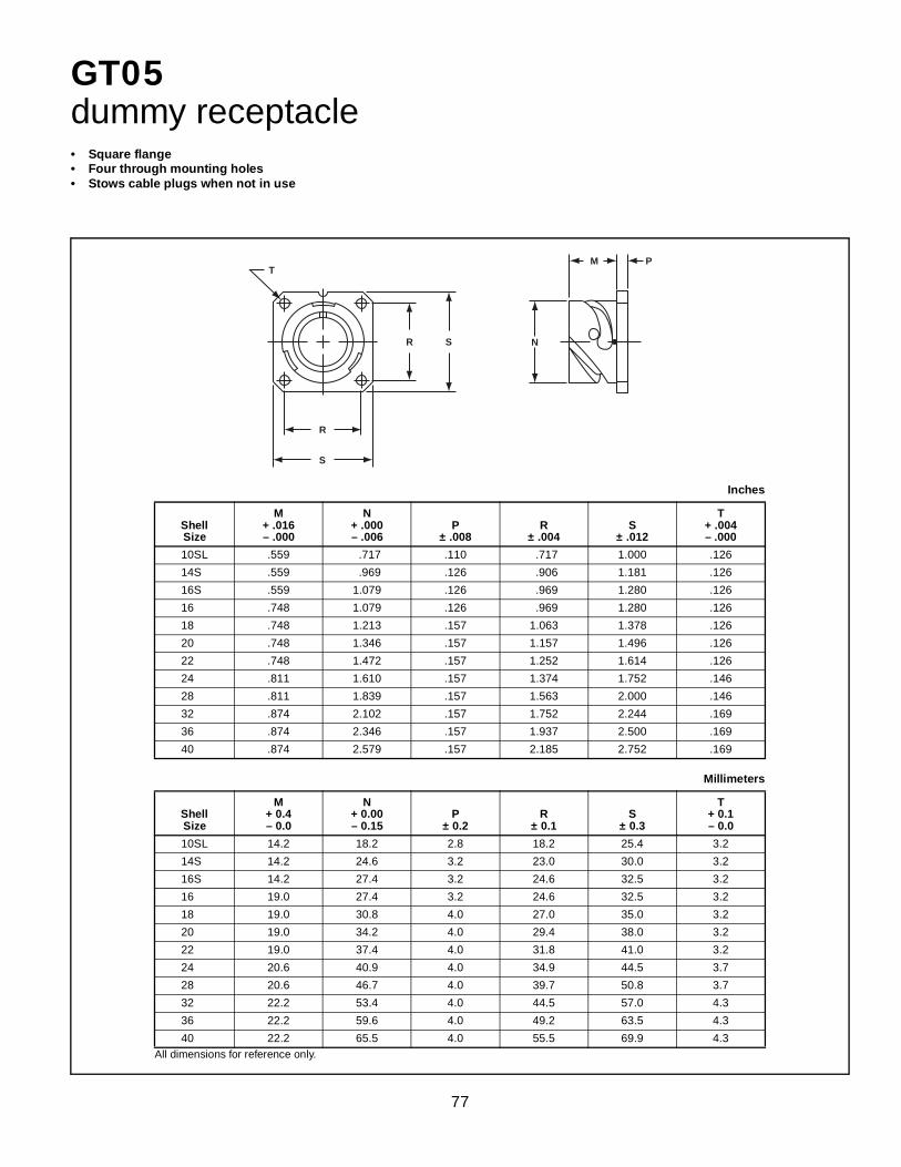
77
GT05dummy receptacle• Square flange• Four through mounting holes• Stows cable plugs when not in use
All dimensions for reference only.
Inches
ShellSize
M+ .016– .000
N+ .000– .006
P± .008
R± .004
S± .012
T+ .004– .000
10SL .559 .717 .110 .717 1.000 .126
14S .559 .969 .126 .906 1.181 .126
16S .559 1.079 .126 .969 1.280 .126
16 .748 1.079 .126 .969 1.280 .126
18 .748 1.213 .157 1.063 1.378 .126
20 .748 1.346 .157 1.157 1.496 .126
22 .748 1.472 .157 1.252 1.614 .126
24 .811 1.610 .157 1.374 1.752 .146
28 .811 1.839 .157 1.563 2.000 .146
32 .874 2.102 .157 1.752 2.244 .169
36 .874 2.346 .157 1.937 2.500 .169
40 .874 2.579 .157 2.185 2.752 .169
Millimeters
ShellSize
M+ 0.4– 0.0
N+ 0.00– 0.15
P± 0.2
R± 0.1
S± 0.3
T+ 0.1– 0.0
10SL 14.2 18.2 2.8 18.2 25.4 3.2
14S 14.2 24.6 3.2 23.0 30.0 3.2
16S 14.2 27.4 3.2 24.6 32.5 3.2
16 19.0 27.4 3.2 24.6 32.5 3.2
18 19.0 30.8 4.0 27.0 35.0 3.2
20 19.0 34.2 4.0 29.4 38.0 3.2
22 19.0 37.4 4.0 31.8 41.0 3.2
24 20.6 40.9 4.0 34.9 44.5 3.7
28 20.6 46.7 4.0 39.7 50.8 3.7
32 22.2 53.4 4.0 44.5 57.0 4.3
36 22.2 59.6 4.0 49.2 63.5 4.3
40 22.2 65.5 4.0 55.5 69.9 4.3
R
R S
S
T
N
M P

78
GTTBthru-bulkhead receptacles
All dimensions for reference only.
Inches
ShellSize
LMax.
M+ .016– .000
N+ .000– .006
P± .008
R± .004
S± .012
T+ .004– .000
10SL 1.488 .717 .717 .110 .717 1.000 .126
14S 1.488 .717 .969 .126 .906 1.181 .126
16S 1.488 .717 1.079 .126 .969 1.280 .126
16 2.049 .846 1.079 .126 .969 1.280 .126
18 2.049 .907 1.213 .157 1.063 1.378 .126
20 2.049 .907 1.346 .157 1.157 1.496 .126
22 2.049 .907 1.472 .157 1.252 1.614 .126
24 2.049 .907 1.610 .157 1.374 1.752 .146
28 2.049 .947 1.839 .157 1.563 2.000 .146
32 2.049 .947 2.102 .157 1.752 2.244 .169
36 2.049 .947 2.346 .157 1.937 2.500 .169
40 2.049 .947 2.579 .157 2.185 2.752 .169
Millimeters
ShellSize
LMax.
M+ 0.4– 0.0
N+ 0.00– 0.15
P± 0.2
R± 0.1
S± 0.3
T+ .004– .000
10SL 37.7 18.2 18.2 2.8 18.2 25.4 3.2
14S 37.7 18.2 24.6 3.2 23.0 30.0 3.2
16S 37.7 18.2 27.4 3.2 24.6 32.5 3.2
16 52.0 21.5 27.4 3.2 24.6 32.5 3.2
18 52.0 23.0 30.8 4.0 27.0 35.0 3.2
20 52.0 23.0 34.2 4.0 29.4 38.0 3.2
22 52.0 23.0 37.4 4.0 31.8 41.0 3.2
24 52.0 23.0 40.9 4.0 34.9 44.5 3.7
28 52.0 24.0 46.7 4.0 39.7 50.8 3.7
32 52.0 24.0 53.4 4.0 44.5 57.0 4.3
36 52.0 24.0 59.6 4.0 49.2 63.5 4.3
40 52.0 24.0 65.5 4.0 55.5 69.9 4.3
• Accepts mating plug on both sides• Four through mounting holes
R
R S
S
T
N N
P M
L

79
GT Connectors – accessories10-40450, 10-36675, 10-580649 sealing gaskets
PLAIN FLAT GASKETThe Amphenol® plain flat gasket of synthetic rubber materialis provided to take complete advantage of waterproof andpressure sealing features. It is for use with the flangemounted receptacle.
SHIELDING GASKETThis flat gasket is provided to give the maximum in connectorperformance. Its special feature is in providing the maximumradio shielding under difficult conditions of high receiver sen-sitivity and low signal strength while retaining the sealingcharacteristics of the plain gasket. This gasket is for use withthe flange mounting receptacle.
LOW TEMPERATURE GASKETThis gasket is provided for applications where the majorrequirement is resistance to the injurious effects of extremelylow temperature. Even at temperatures as low as –67°F thisgasket retains its resiliency and will seal a pressure differen-tial of 30 psi.
Additional versions of gaskets are available including lowsmoke zero halogen, and also high temperature and conduc-tive types. Consult Amphenol lndustrial Operations, SidneyNY, for further information.Installation Dimensions
MSShellSize
A± .010
Front Panel Versions
B+ .016– .000
Rear Panel Version
B+ .016– .000
C+ .016– .000
D± .010
10SL .719 .625 .724 1.000 .172
14S .906 .875 .976 1.188 .172
16S .969 1.000 1.087 1.281 .172
16 .969 1.000 1.087 1.281 .172
18 1.063 1.125 1.220 1.375 .203
20 1.156 1.250 1.354 1.500 .203
22 1.250 1.375 1.480 1.625 .203
24 1.375 1.500 1.618 1.750 .203
28 1.563 1.750 1.846 2.000 .203
32 1.750 2.000 2.110 2.250 .219
36 1.938 2.188 2.354 2.500 .219
40 2.188 2.438 2.587 2.750 .219
Installation Dimensions
MSShellSize
A± 0.2
Front Panel Versions
B+ 0.4– 0.0
Rear Panel Version
B+ 0.4– 0.0
C+ 0.4– 0.0
D± 0.2
10SL 18.2 15.9 18.4 25.4 4.36
14S 23.0 22.2 24.8 30.2 4.36
16S 24.6 25.4 27.6 32.5 4.36
16 24.6 25.4 27.6 32.5 4.36
18 27.0 28.57 31.0 35.0 5.15
20 29.4 31.75 34.4 38.1 5.15
22 31.8 34.9 37.6 41.2 5.15
24 34.9 38.1 41.1 44.5 5.15
28 39.7 44.45 46.9 50.8 5.15
32 44.5 50.8 53.6 57.2 5.56
36 49.2 55.57 59.8 63.5 5.56
40 55.6 61.92 65.7 69.9 5.56
Order Data forFront Panel Mount Gaskets
Front Panel Plain Version
Front PanelShielding Version
Front PanelLow Temperature
Version
Front PanelLow Smoke ZH
Version
10-40450-10 10-40450-10S 10-36675-10 LS-40450-10
10-40450-14 10-40450-14S 10-36675-14 LS-40450-14
10-40450-16 10-40450-16S 10-36675-16 LS-40450-16
10-40450-18 10-40450-18S 10-36675-18 LS-40450-18
10-40450-20 10-40450-20S 10-36675-20 LS-40450-20
10-40450-22 10-40450-22S 10-36675-22 LS-40450-22
10-40450-24 10-40450-24S 10-36675-24 LS-40450-24
10-40450-28 10-40450-28S 10-36675-28 LS-40450-26
10-40450-32 10-40450-32S 10-36675-32 LS-40450-32
10-40450-36 10-40450-36S 10-36675-36 LS-40450-36
10-40450-40 10-40450-40S 10-36675-40 LS-40450-40
Order Data forRear Panel Mount Gaskets
Rear PanelPlain Version
Rear PanelLow Smoke ZH
Version
10-580649-11 LS-580649-11
10-580649-14 LS-580649-14
10-580649-16 LS-580649-16
10-580649-18 LS-580649-18
10-580649-20 LS-580649-20
10-580649-22 LS-580649-22
10-580649-24 LS-580649-24
10-580649-26 LS-580649-26
10-580649-32 LS-580649-32
10-580649-36 LS-580649-36
10-580649-40 LS-580649-40
C
A
CA
BD4 HOLES
.031± .010
.08 ± 0.3 mm
.020 ± .0040.5 ± 0.1 mmSHIELDING
.031 ± .0100.8 ± 0.3 mmLOWTEMPERATURE

80
GT Connectors – accessoriesreceptacle protection caps
* To complete order number, add shell size and suffix number. For example, shell size 11 with olive drab cadmium plate would be10-580902-113.
All dimensions for reference only.
Inches
ShellSize
D+ .020– .000
LMax.
NMax.
LLApprox.
11 .173 .700 .905 5.000
14 .173 .700 1.181 5.000
16 .173 .700 1.280 5.000
17 .173 .900 1.280 5.000
18 .173 .900 1.457 5.000
20 .173 .900 1.594 5.000
22 .173 .900 1.713 5.000
24 .173 .900 1.850 5.000
28 .220 .900 2.126 7.480
32 .261 .900 2.382 7.480
36 .261 .900 2.638 7.480
40 .261 .900 2.874 7.480
Millimeters
ShellSize
D+ 0.5– 0.0
LMax.
NMax.
LLApprox.
11 4.4 17.8 23.0 127
14 4.4 17.8 30.0 127
16 4.4 17.8 32.5 127
17 4.4 22.9 32.5 127
18 4.4 22.9 37.0 127
20 4.4 22.9 40.5 127
22 4.4 22.9 43.5 127
24 4.4 22.9 47.0 127
28 5.6 22.9 54.0 190
32 5.6 22.9 60.5 190
36 5.6 22.9 67.0 175
40 5.6 22.9 73.0 190
Finish Suffix
Black anodize -XXZ
Olive drab cadmium plate -XX3
Olive drab cadmium nickel base -XX9
Electroless nickel -XXG
Green zinc cobalt -XXU
Black zinc cobalt -XXY
• Protective metal caps which seal the front of receptacles• Includes a chain for retention of the cap at the required
location• For receptacles: GT00, 01, 02, 020, 030, 070
* 10-580902-XXX
D
LL
L
N

81
GT Connectors – accessoriesplug protection caps• Protective metal caps which seal the front of plugs• Includes a chain for retention of the cap at the required
location• For plugs: GT06, 08
* To complete order number, add shell size and suffix number. For example, shell size 11 with olive drab cadmium plate would be10-580903-113.
All dimensions for reference only.
Inches
ShellSize
D+ .020– .000
LMax.
NMax.
LLApprox.
11 .157 .945 .807 5.000
14 .157 .945 1.059 5.000
16 .157 .945 1.169 5.000
17 .157 .945 1.169 5.000
18 .157 .945 1.303 5.000
20 .189 1.260 1.437 5.520
22 .189 1.260 1.563 5.520
24 .189 1.260 1.701 5.520
28 .220 1.260 1.929 7.480
32 .261 1.260 2.193 7.480
36 .261 1.260 2.437 7.480
40 .261 1.260 2.665 7.480
Millimeters
ShellSize
D+ 0.5– 0.0
LMax.
NMax.
LLApprox.
11 4.0 24 20.5 127
14 4.0 24 26.9 127
16 4.0 24 29.7 127
17 4.0 24 29.7 127
18 4.0 24 33.1 127
20 4.8 32 36.5 140
22 4.8 32 39.7 140
24 4.8 32 43.2 140
28 4.8 32 49.0 190
32 5.6 32 55.7 190
36 5.6 32 61.9 190
40 5.6 32 67.7 190
Finish Suffix
Black anodize -XXZ
Olive drab cadmium plate -XX3
Olive drab cadmium nickel base -XX9
Electroless nickel -XXG
Green zinc cobalt -XXU
Black zinc cobalt -XXY
* 10-580903-XXX
D
LL
N
L

82
GT Connectors – accessoriesMS3057-A style cable clamp
All dimensions for reference only.
Inches
PartNumber
Used withShell Size
Used withBushing B D G F
VThread
Class 2B
97-3057-1004 10SL MS3420-4 .315 .395 .812 .866 .6250-24 UNEF
97-3057-1007 14S MS3420-6 .442 .395 .875 1.063 .7500-20 UNEF
97-3057-1008 16 - 16S MS3420-8 .568 .395 .945 1.145 .8750-20 UNEF
97-3057-1010 18 MS3420-10 .633 .395 .945 1.244 1.0000-20 UNEF
97-3057-1012 20 - 22 MS3420-12 .758 .395 .945 1.475 1.1875-18 UNEF
97-3057-1016 24 - 28 MS3420-16 .948 .395 1.031 1.700 1.4375-18 UNEF
97-3057-1020 32 MS3420-20 1.256 .460 1.094 2.055 1.7500-18 UNS
97-3057-1024 36 MS3420-24 1.380 .520 1.157 2.265 2.0000-18 UNS
10-824810-028 40 MS3420-28 1.625 .520 1.685 2.683 2.2500-16 UN
Millimeters
PartNumber
Used withShell Size
Used withBushing B D G F
97-3057-1004 10SL MS3420-4 8.0 10.0 20.6 22
97-3057-1007 14S MS3420-6 11.0 10.0 22.2 27
97-3057-1008 16 - 16S MS3420-8 14.4 10.0 24.0 29
97-3057-1010 18 MS3420-10 16.1 10.0 24.0 32
97-3057-1012 20 - 22 MS3420-12 19.2 10.0 24.0 37
97-3057-1016 24 - 28 MS3420-16 24.1 10.0 26.2 43
97-3057-1020 32 MS3420-20 31.9 11.7 27.8 52
97-3057-1024 36 MS3420-24 35.0 13.2 29.4 58
10-824810-028 40 MS3420-28 41.3 13.2 42.8 68
• Concentric cable clamps, insure strain relief and centrallocation of the cable
• Can be used with bushing MS3420
B
Q
FE
V
G
D

83
GT Connectors – accessoriesMS3420 bushing
All dimensions for reference only.
Inches
PartNumber
Used withCable Clamp A B C D
MS3420-3 M85049/41-3A .130 .210 .379 2.875
MS3420-4 M85049/41-4A .220 .302 .505 2.750
MS3420-6 M85049/41-6A .312 .427 .619 2.625
MS3420-8 M85049/41-8A .437 .552 .744 2.500
MS3420-10 M85049/41-10A .562 .615 .889 2.375
MS3420-12 M85049/41-12A .625 .740 1.084 2.250
MS3420-16 M85049/41-16A .750 .927 1.314 2.125
MS3420-20 M85049/41-20A .937 1.240 1.598 2.000
MS3420-24 M85049/41-24A 1.250 1.365 1.847 1.875
MS3420-28 M85049/41-28A 1.375 1.614 2.085 1.750
Millimeters
PartNumber
Used withCable Clamp A B C D
MS3420-3 M85049/41-3A 3.30 5.3 9.60 73.0
MS3420-4 M85049/41-4A 5.58 7.7 12.80 69.8
MS3420-6 M85049/41-6A 7.92 10.8 15.70 66.8
MS3420-8 M85049/41-8A 11.09 14.0 18.90 63.5
MS3420-10 M85049/41-10A 14.27 15.6 22.58 60.3
MS3420-12 M85049/41-12A 15.87 18.8 27.50 57.1
MS3420-16 M85049/41-16A 19.05 23.5 33.40 53.9
MS3420-20 M85049/41-20A 23.79 31.5 40.60 50.8
MS3420-24 M85049/41-24A 31.75 34.7 46.90 47.6
MS3420-28 M85049/41-28A 34.92 41.0 52.90 44.4
• Bushing of synthetic rubber to be used with cable clamps for protection of the cable or wires
• Can be telescoped for smaller cable diameters
A
C
D1.6mm.062 in.
B

84
GT Connectors – accessoriesMS3057-C style (10-350349) cable clamp
PartNumber
Used withShell Size
A ThreadClass 2Bin inches
V ThreadClass 2Ain inches
Used with Bushing
Bushing OpeningInches
Busing OpeningMillimeters
Open Closed Open Closed
10-350349-123 10SL .6250-24 UNEF 6-32 UNC MS3420-4A .219 .010 5.56 0.25
10-350349-143 14S .7500-20 UNEF 6-32 UNC MS3420-6AMS3420-4A
.312
.219.114.020
7.935.56
2.890.50
10-350349-163 16 & 16S .8750-20 UNEF 6-32 UNC MS3420-8AMS3420-6A
.437
.312.220.085
11.107.93
5.602.15
10-350349-183 18 1.0000-20 UNEF 6-32 UNC MS3420-10AMS3420-6A
.437
.312.197.085
11.107.93
5.002.15
10-350349-203 20 & 22 1.1875-18 UNEF 8-32 UNC MS3420-12AMS3420-8A
.541
.437.270.177
13.7411.10
6.854.50
10-350349-243 24 & 28 1.4375-18 UNEF 8-32 UNCMS3420-16AMS3420-12AMS3420-8A
.748
.541
.437
.429
.260
.186
19.0013.7411.10
10.906.604.72
10-350349-323 32 1.7500-18 UNS .250-20 UNCMS3420-20AMS3420-16AMS3420-12A
.937
.748
.541
.620
.441
.273
23.8019.0013.74
15.7411.206.93
10-350349-363 36 2.0000-18 UNS .250-20 UNCMS3420-24AMS3420-20AMS3420-16A
1.122.937.748
.681
.504
.358
28.5023.8019.00
17.3012.809.10
10-350349-403 40 2.2500-16 UN .250-20 UNCMS3420-28AMS3420-20AMS3420-16A
1.250.937.748
.815512368
31.7523.8019.00
20.7013.009.34
All dimensions for reference only.
Inches
PartNumber
Used withShell Size
BE
± .016F
± .008
G+ .020– .000Open Closed
10-350349-123 10SL .312 .094 .748 .890 1.272
10-350349-143 14S .438 .230 .874 1.016 1.272
10-350349-163 16 & 16S .531 .315 1.000 1.106 1.272
10-350349-183 18 .625 .378 1.122 1.220 1.390
10-350349-203 20 & 22 .748 .445 1.311 1.469 1.406
10-350349-243 24 &28 .937 .610 1.559 1.654 1.516
10-350349-323 32 1.250 .921 1.874 2.126 1.764
10-350349-363 36 1.378 .921 2.122 2.248 2.031
10-350349-403 40 1.624 1.177 2.374 2.500 2.031
Millimeters
BE
± 0.4F
± 0.2
G+ 0.5– 0.0Open Closed
7.93 2.38 19.0 22.6 32.3
11.12 5.84 22.2 25.8 32.3
13.48 8.00 25.4 28.1 32.3
15.87 9.60 28.5 31.0 35.3
19.00 11.30 33.3 37.3 35.7
23.80 15.50 39.6 42.0 38.5
31.75 23.40 47.6 54.0 44.8
35.00 23.40 53.9 57.1 51.6
41.25 29.90 60.3 63.5 51.6
• Waterproof clamp for jacketed cables• Provides mechanical strain relief plus concentric clamping over a
wide range of cable sizes• A neoprene* gland seal ensures a waterproof seal on the cable jacket
* Other materials available
F
V
EB
GA
To reduce diameter B, userubber brushing MS3420A
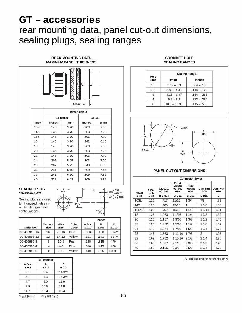
85
GT – accessoriesrear mounting data, panel cut-out dimensions,sealing plugs, sealing ranges
REAR MOUNTING DATAMAXIMUM PANEL THICKNESS
Size
Dimension D
GT00/020 GT030
Inches (mm) Inches (mm)
10SL .146 3.70 .303 7.70
14S .146 3.70 .303 7.70
16S .146 3.70 .303 7.70
16 .145 3.70 .242 6.15
18 .145 3.70 .303 7.70
20 .145 3.70 .303 7.70
22 .145 3.70 .303 7.70
24 .207 5.25 .303 7.70
28 .207 5.25 .343 8.70
32 .241 6.10 .309 7.85
36 .241 6.10 .309 7.85
40 .237 6.02 .309 7.85
PANEL CUT-OUT DIMENSIONS
ShellSize
A Dia.Hole Size
Connector Styles
02, 020, 00, 030
Front Mount 02, 00,
020
Rear Mount
030Jam Nut
070Jam Nut
070
B ±.004 C Dia. C Dia. D Dia. E
10SL .126 .717 11/16 1 3/4 7/8 .83
14S .126 .906 13/16 1 1 1/8 1.08
16S/16 .126 .969 15/16 1 1/8 1 1/14 1.21
18 .126 1.063 1 1/16 1 1/4 1 3/8 1.32
20 .126 1.157 1 3/16 1 3/8 1 1/2 1.45
22 .126 1.252 1 5/16 1 1/2 1 5/8 1.57
24 .146 1.374 1 7/16 1 5/8 1 3/4 1.70
28 .146 1.563 1 11/16 1 7/8 2 1.95
32 .169 1.752 1 15/16 2 1/8 2 1/4 2.20
36 .169 1.937 2 1/8 2 3/8 2 1/2 2.45
40 .169 2.185 2 3/8 2 5/8 2 3/4 2.70
SEALING PLUG10-405996-XX
Sealing plugs are usedto fill unused holes in multi-holed grommet configurations.
GROMMET HOLESEALING RANGES
Hole Size
Sealing Range
(mm) Inches
16 1.62 – 3.3 .064 – .130
12 2.89 – 4.31 .114 – .170
8 4.16 – 6.47 .164 – .255
4 6.9 – 9.3 .272 – .370
0 10.5 – 13.97 .415 – .550
** ± .020 (in.) *** ± 0.5 (mm)
Order No.Contact
SizeWireSize
Color Code
Inches
A Dia.±.010
B±.005
C±.010
10-405996-16 16 20-16 Blue .083 .133 .564**
10-405996-12 12 14-12 Yellow .121 .171 .564**
10-405996-8 8 10-8 Red .185 .315 .470
10-405996-4 4 4-6 Blue .310 .415 .470
10-405996-0 0 0-2 Yellow .440 .605 1.000
Millimeters
A Dia.± 0.2
B± 0.1
C± 0.2
2.1 3.4 14.3***
3.1 4.3 14.3***
4.7 8.0 11.9
7.9 10.5 11.9
11.2 15.4 25.4
All dimensions for reference only.
D MAX.
B DIA.
A DIA.
45O
C.135
3.4 + 0.8 – 0.6 mm
+.030 –.025 in.
B TYP.
C DIA.
A DIA.
E TYP.
D DIA.

86
CRIMP CONTACTSCRIMP CONTACT DATA APPLICATION TOOLS
PART NUMBER
MATING SIZE
WIRE WELL Crimp Tools
Positioner/Die Set
Locator/Color
PIN CONTACT SOCKET CONTACT
SILVER GOLD(“D”) SILVER GOLD(“D”)
10-40553 10-597160-15D 10-597109-161 10-597109-16D
16S
16-18-20
Daniels AF8 or Equivalent
TH29-1 orEquivalent
Red
10-606014-40 10-597160-40D 10-597109-401 10-597109-40D 12-14
10-606014-221 10-597160-19D 10-597109-191 10-597109-19D 14-16
10-606014-291 10-597160-34D 10-597109-341 10-597109-34D 20-22
10-606014-46 10-597160-46D 10-597109-461 10-597109-46D 20-24
10-40557 10-597160-16D 10-597109-171 10-597109-17D
16
16-18-20
Pin - BlueSocket - Green
10-606014-022 10-597160-22D 10-597109-221 10-597109-22D 12-14
10-606014-171 10-597160-17D 10-597109-141 10-597109-14D 14-16
10-606014-311 10-597160-33D 10-597109-331 10-597109-33D 20-22
10-606014-361 10-597160-36D 10-597109-361 10-597109-36D 20-24
10-606014-121 10-597160-12D 10-597109-131 10-597109-13D
12
12-14
Green
10-606014-231 10-597160-23D 10-597109-231 10-597109-23D 8-10
10-606014-251 10-597160-26D 10-597109-261 10-597109-26D 10-12
10-606014-271 10-597160-27D 10-597109-271 10-597109-27D 14-16-18
10-606014-261 10-597160-24D 10-597109-241 10-597109-24D 18-20
10-606014-201 10-597160-20D 10-597109-201 10-597109-20D 20-22
10-40792 10-597160-8D 10-40793 10-597109-8D
8
8
Pico 400BHD
Pico 414DA-8NPico
Pin - 4025Socket - 4026
10-606014-41 10-597160-41D 10-597109-411 10-597109-41D 6
10-606014-321 10-597160-28D 10-606015-321 10-597109-28D 10-12
10-606014-381 10-597160-38D 10-597109-381 10-597109-38D 12-14
10-40564 10-597160-4D 10-40565 10-597109-4D
4
4
Pico 414DA-4N Pico 404310-606014-58 10-597160-58D 10-597109-581 10-597109-58D 6
10-606014-331 10-597160-35D 10-597109-351 10-597109-35D 8
10-606014-44 10-597160-44D 10-606015-441 10-597109-44D 10
10-581806-000 10-597160-1D 10-581808-000 10-597159-1D
0
0
Pico 414DA-0NPico
Pin - 4042-1Socket - 4042
10-606014-341 10-597160-29D 10-597109-291 10-597109-29D 0-2
10-606014-351 10-597160-30D 10-606015-351 10-597109-30D 4
10-597276-48 10-597276-48D 10-606015-48 10-597109-48D 2/0 2/0Pico 500
Pico 514DA2/0N PicoPin - 6490
10-597276-47 10-597276-47D 10-606015-47 10-597109-47D 4/0 4/0 Pico 514DA4/0N Socket - 6491
Machined from copper alloys and silver or gold plated for maximum corrosion resistance, with a mini-mum millivolt drop and a maximum current carrying capacity, the size 16 and 12 socket contacts are ofthe closed entry design. Crimp contacts are available for all MS insert arrangements and are identifiedwith an Amphenol® proprietary number.
GT Connectorscrimp contacts and application tools
See page 87 for further contact information applicable to both crimp and solder contacts.Additional contact variations including thermocouple and RADSOK power contacts are available; consult Amphenol, Sidney, NY for information.

87
Machined copper alloy contacts in a full range of sizes, with closed entry socket design in thesize 12 and 16 contacts. A heavy silver-plated finish is deposited on all MS style solder con-tacts for maximum corrosion resistance, maximum current carrying capacity and low millivoltdrop. Gold plated contacts are also available. (See how to order, pg. 88).
Pin/Socket
Mating EndSize
Wire BarrelSize
AllowableWire Size
Test Current**Amps
Pin
Socket16 Short† 16
16182022
13107.55
Pin
Socket16 Long 16
16182022
13107.55
Pin
Socket12 12 12
142317
Pin
Socket8 8
810
4633
Pin
Socket4 4
46
8060
Pin
Socket0 0
012
150125100
** Contact ratings as stated are test ratings only. The connector may not withstand full rated current through all contacts continuously. Please note that the electrical data given is not an establishment of electrical safety factors. This is left entirely in the designer’s hands as he can best determine which peak voltage, switching surges, transients, etc. can be expected in a particular circuit.
Table IMIL-SPEC CONTACT ARRANGEMENT
SERVICE RATING
MSService Rating
RecommendedOperating Voltage*
at Sea Level
Effective Creepage Distance
Nom.
Mechanical Spacing
Nom.DC AC (RMS)
Inst. 250 200 1/16
A 700 500 1/8 1/16
D 1250 900 3/16 1/8
E 1750 1250 1/4 3/16
B 2450 1750 5/16 1/4
C 4200 3000 1 5/16
* The values listed in Table I represent operating valueswhich include a generous safety factor. It may be nec-essary for some applications to exceed the operatingvoltages listed here. If this is necessary, designers willfind Table II useful for determining the degree to whichthe recommended values of Table I can be exceeded.
Table II
ALTITUDE VOLTAGE DERATING** CHART
† Not corrected for changes in density due to variations in temperature
** No attempt has been made to recommend operating voltages. The designer must determine his own oper-ating voltage by the application of a safety factor to the above derating chart to compensate for circuit tran-sients, surges, etc.
MSService Rating
NominalDistance
Standard SeaLevel Conditions
Pressure Altitude †50,000 Feet
Pressure Altitude †70,000 Feet
Airspace Creepage
Minimum Flashover
VoltageAC (RMS)
TestVoltage
AC (RMS)
Minimum Flashover
VoltageAC (RMS)
TestVoltage
AC (RMS)
Minimum Flashover
VoltageAC (RMS)
TestVoltage
AC (RMS)
Inst. 1/32 1/16 1400 1000 550 400 325 260
A 1/16 1/8 2800 2000 800 600 450 360
D 1/8 3/16 3600 2800 900 675 500 400
E 3/16 1/4 4500 3500 1000 750 550 440
B 1/4 5/16 5700 4500 1100 825 600 480
C 5/16 1 8500 7000 1300 975 700 560
GT Connectorssolder contacts
† The 10SL, 14S and 16S connectors require short contacts.

88
Amphenol GT Connectorshow to order, connector intermateability
Part Number SystemGT C 00 A FF 36-5 P W (014)
1 2 3 4 5 6 7 8
1. Contact Style and Insert MaterialC = CrimpCN = Crimp with stainless steelS = SolderSN = Solder with stainless steelCY = Crimp with VitonSY = Solder with VitonCL = Crimp with low smoke/flame retardant insertsSL = Solder with low smoke/flame retardant insertsNo designation required for Neoprene components
2. Shell Style00 - Wall mount receptacle01 - Inline receptacle02 - Box mount receptacle020 - Box mount receptacle with accessory threads030 - Square flange receptacle - rear panel mount05 - Dummy receptacle06 - Straight plug062 - Straight plug with deep serrated coupling nut*064 - Panel mounted plug with heavy duty coupling nut065 - Straight plug with long heavy duty coupling nut07 - Jam nut receptacle - rear panel mount070 - Jam nut receptacle with accessory threads08 - 90° angle plugTB - Thru-bulkhead
3. Connector Class - For details, see pages 29-78A - Adapter for accessory attachment, non-environmental
AF - Adapter, clamp for individual wires, non-environmental
CF - Adapter, jacketed cable clamp, environmental
CFGG- Adapter, jacketed cable clamp, over molded coupling nut,environmental
CFZ - Adapter, jacketed cable clamp, individual wire sealinggrommet, environmental
F - Adapter, clamp for individual wires, individual wire sealinggrommet, environmental.
G - Adapter for heat shrink tubing, individual wire sealinggrommet, environmental
G2 - Free turning adapter for heat shrink tubing, individual wiresealing grommet, environmental
GTTB - Thru bulkhead receptacle, accepts mating plug on both sides
LC - Long adapter, backshell with jacketed cable basket weavegrip, with individual wire sealing grommet, environmental
LCF - Long adapter, jacketed cable clamp, environmental
LCFZ - Long adapter, jacketed cable clamp, individual wire sealinggrommet, environmental
LT - Adapter, backshell for terminating metallic core conduit
PFC - Adapter, backshell for plastic corrugated conduit, individualwire sealing grommet, environmental
PG - Long adapter with PG threads, individual wire sealinggrommet, environmental
PP - Panel mounted plug
R - Adapter for accessory attachment, individual wire sealinggrommet, environmental
R - (02/03) No thread, no accessories, environmental with panelsealing gasket
R - (020) No accessories, environmental with panel sealinggasket
RFS - (02) No accessories, countersunk mounting holes for usewith over molded coupling nut, environmental with panelsealing gasket
RFSM - (020) No accessories, countersunk mounting holes for usewith over molded coupling nut, environmental with panelsealing gasket
RV - Adapter, individual wire sealing grommet, environmental
SB - Adapter for termination of EMI/RFI shielded braid with heatshrink tubing or boot, individual wire sealing grommet,environmental
SBT - Adapter for termination of EMI/RFI shielded braid with heatshrink tubing or boot, individual wire sealing grommet,environmental
SL - Long adapter, jacketed cable liquid tight strain relief,environmental
4. Designation for Mounting Hole - Receptacle OnlyFF - UN ThreadsFM - Metric ThreadsNo designation for standard through hole mounting holes.
5. Shell Size and ArrangementSee pages 2–4
6. Contact StyleP designates pin contactsS designates socket contacts
7. Alternate PositionW, X, Y and Z - See page 5.No suffix required for normal position.
8. Connector Modification*Omit for standard olive drab with silver plated contactsi.e.: (014) Olive drab cadmium plate, nickel base
(B30) gold/nickel plated contacts(025) Black zinc cobalt(027) Conductive black zinc cobalt(024) Green zinc cobalt(LC) Less contacts
MATEABILITY WITHIDENTICAL CONTACT ARRANGEMENTS
Connector Style Mateable with Style
GT00 GT06 / 062 / 064 / 065 / 08
GT01 GT06 / 062 / 064 / 065 / 08
GT02 GT06 / 062 / 064 / 065 / 08
GT020 GT06 / 062 / 064 / 065 / 08
GT030 GT06 / 062 / 064 / 065 / 08
GT06 / 062 / 064 / 065 GT00 / 01 / 02 / 020 / 03 / 030 / 05 / 070 / TB
GT07 / 070 GT06 / 062 / 064 / 065 / 08
GT08 GT00 / 01 / 02 / 020 / 03 / 030 / 05 / 070 / TB
GTTB GT06 / 062 / 064 / 065 / 08
®
* Consult Amphenol, Sidney, NY

89
Amphenol GT Connectorswith RADSOK technology
Amphenol offers Amphe-Power Connectors, high amperagecapability connectors designed for the most demanding industrialand transportation applications. The GT connectors, in most shellstyles, can be enhanced with RADSOK contacts that handle upto 150% higher amperages than standard contacts.
The RADSOK contact is a hyperbolic, stamped grid configurationwithin the socket. As male pin is inserted, axial members in thefemale half deflect, imparting high current flow across the con-nection with minimal voltage loss. This design ensures a large,coaxial, face-to-face surface area engagement and provideshigher current capacity with minimized temperature rise. TheRADSOK’s strongest benefit is its very low mill-volt drop becauseof the intimate contact provided by the spring force of the grid.RADSOK contacts are available in size 8 (69 amps), size 4 (120amps), and size 0 (250 amps). Current Amphe-Power lines sup-port from 50A to 500A continuous duty. Hybrid arrangementswith RADSOK and power contacts can be tailored to meet cus-tomer needs.
For more information on GT Amphe-Power Connectors, requestBrochure SL-391.
The RADSOK Contact Advantage:• Low contact Resistance• Low milli-volt drop performance • Higher current capacity with minimized temperature rise.• Reliability under vibration and shock.• High quality, consistency and lower cost
Amphe-Power™ Amphe-GTRThe Amphe-Power™ GT series provides the benefit of a GT con-nector in a high performance composite material. The GT-R islisted to UL/CUL 2238 Standard, Control Number 19VP. It alsomeets all of the specifications for high power process control andserver applications. Performance level is the same as that of theGT series. RADSOK contacts enable an increased current ratingof 120A on individual contacts, and a standard PG threadachieves an IP67 seal rating.
Compression (setscrew) wire termination to the 4/6AWG or 8/10AWG conductors allows for easy field replacement of pin orsocket contacts. It also provides for easy complete plug or recep-tacle assemblies, all without a need for specialized tooling.
Power GTThe Power GT is a modification to the GT series incorporatingthree 8.0mm RADSOK contacts mounted in a common termina-tion to busbar or cable, enhanced to an ultra-high current densityin a compact shell size 28 layout. This design created the firstTUV “finger-proof” 500A connector in the marketplace with the“dead-front” pin design to prevent contact with live circuits. Inenvironmental versions, this connector achieves IP67 perfor-mance.
The ninety-degree wire orientation on the plug provides low-pro-file mounting for tight packaging requirements. This plug isdesigned to be over-molded, and can also be fitted with mechan-ical hardware for individual requirements.
Amphenol ®GT Amphe-Power Connectorswith RADSOK ® high amperage contacts
®
Amphe-Power Composite GTR Connector
Power GT, Finger-Proof 500A Connector

90
GTC-M Series - The GT with Metal Clip InsertsAmphenol’s GTC-M series combines the GT reverse bayonet con-nector and the rear release metal clip retention system which isused in the Amphenol®/Matrix® MIL-C-5015 connector line.Another benefit is the captivated coupling nut assembly whichallows unmating without the rear accessories attached.
Improved environmental sealing is achieved with this series. Thecrimp joint is covered by a three-webbed fluorinated silicone grom-met that seals on the wires without the necessity of an additionalsealing clamp. An interfacial seal with conical towers on the pininsert matches with recesses on the socket; a match that providesthe popular “cork and bottle” seal during mating. The grommet andthe interfacial seal provides adequate sealing during environmen-tal extremes. The GTC-M series is intermateable and intermount-able with the standard GT series, and it uses standard M85049style rear accessories. For more information on the GTC-M Series,request Product Data Sheet #181.
GT-PC Connectors for High Voltage Power ApplicationsThe Amphenol® GT-PC connectors were developed for use in theHigh Voltage Power Distribution industry. Incorporating all thestandard features of the popular GT series, these connectors willprevent accidental electrical shocks to the technicians. “DeadFront” pin contacts in size 0 are recessed into a socket insert, pre-venting inadvertent contact with a live circuit. Higher amperagelevels are provided - up to 100 amps per contact. The GT-PCseries has been UL approved. “First Mate - Last Break” features onone or more of the pins provide an additional measure of operatorsafety. Currently there are 5 insert patterns available. ConsultAmphenol Industrial Operations for more information.
GT Connectors for the HMI Lighting IndustryAmphenol provides GT connectors for the rugged use experiencedduring stage shows and other entertainment events, even outsidein the elements. The same 3-point bayonet coupling system andthe same ruggedness to survive 2000 mating cycles are provided.The unique features of this connector series include color-codedreceptacle shells with matching backshells on the cable plugs. Thecolors can be matched to specific wattage cables and/or light sys-tems. A wide selection of environmental adapters designed to sealon the outside diameter of specific cable diameters can be fitted tothe backshells. Applications for these connectors include powerand control of lighting trusses, and portable power and dimmerracks. For more information request Product Data Sheet #174.
Amphenol ® GTC-M with Metal Clip Inserts
Amphenol ® GT-PC Connectors for High VoltagePower Applications
Amphenol ® GT Connectors for the HMI Lighting Industry
Amphenol GT Connectorsspecial applications
®

91
Additional Amphenol Industrial Connectorsfor the Rail Industry
ARCL SeriesAmphenol has developed a heavy duty 5015 type connector with38999 Series III type coupling for use in mass transportation andheavy equipment applications. The ARCL Series has the sameelectrical characteristics as 5015 standard product but it has rug-ged ratchet double start stub threads. These rugged double stubthreads eliminate mis-mating and provide for easy cleaning.
Other features/benefits of the ARCL connector series:
• 5 key/keyway alignment feature.• Operating temperature is from –55°C to +125°C.
Operating voltage is to 3000 VAC (RMS) at sea level.• Crimp and solder termination available.• 5 shell styles with all the 5015 insert patterns available.• Supplied with low smoke, low halogen inserts which are
flame retardant, but also can be supplied with standard 5015 inserts.
• Wide variety of backend accessories for all styles of cable and conduit, and a variety of cable strain reliefs including over-molding and heat shrink boots.
• RADSOK high amperage sockets can be incorporated.
Star-Line® SeriesAmphenol/Pyle Star-Line Series is another heavy duty environ-mental cylindrical connector widely used in mass transportationand in the oil exploration market. Ideal for high amperage andhigh density control and instrumentation applications, this serieshas features and benefits as follows;
• Hard anodic coating for dielectric strength with heat and cor-rosion resistance.
• Operating temperature is from –67°F to +257°F.Amperages up to 1135 amps at 1000VAC or DC rating avail-able.
• Double lead Acme threads provide complete coupling in one turn of the coupling nut, and do not clog under adverse weather conditions.
• Solder, crimp and pressure terminals; circuit breaking power and control types available.
• UL listed and CSA listed for circuit breaking capability.• 5 shell styles with over 150 insert patterns.• 3 retention styles with captive contacts or insertable/remov-
able contacts.• Variety of backend accessories including basketweave cable
grips, straight or angled adapters and receptacles mounted to junction boxes.
Over-Molded CableCables can be designed with custom overmold to AmphenolIndustrial cylindrical connectors for almost any application inmass transportation or any other types of industrial markets.Overmold seals to the rear of the connector and to the cablejacket to provide moisture sealing. Cables may be designed tomeet any environmental performance requirement and any elec-trical performance requirement. Variety of materials are avail-able: neoprene, hypalon and others.
Consult Amphenol Industrial Operations for further informationon these industrial products.
Amphenol ® ARCL Series
Amphenol® Star-Line® Series
Over-Molded Cable for Industrial Connectors

92
Additional Amphenol Industrial Productsfor the Rail Industry, cont.
Trans-Power® ConnectorsAmphenol/Pyle provides head-end power connectors for com-mercial rail systems. These meet Amtrak specification D-77-24,APTA #RP-E-016. Features and benefits include:
• Slip-fit, double seated for environmental protection.• Retention by receptacle cover or optional accessories.• Crimp termination per Amtrak and APTA specifications.• Socket contacts provide uniform pressure for low mating and
unmating forces, low voltage drop, consistently low tempera-ture rise and shock resistance.
• Operating ambient temperature is –57°F to +110°F.Electrical performance up to 600 volts, 400 Amps.
• All molded elastomeric rubber body on jumper. Raintight per U/L standard.
27 Pole Train-line Receptacles and JumpersAmphenol/Pyle 27 pole MU (multiple unit) and communicationreceptacles and jumpers are provided for rail applications. Jump-ers are either standard car to car, between locomotives orbetween locomotives and lead cars. These products aredesigned to Amtrak and APTA specifications. Other design fea-tures and benefits:
• Locomotive jumpers are keyed differently from all other 27 pole jumpers to prevent mis-mating. They also have identifi-cation markings to distinquish their proper usage on locomo-tives.
• Receptacles are a rugged aluminum housing with a spring loaded cover. Receptacles can be provided with or without leads.
• Push-pull mating.
Amphe-Y Composite Molded ConnectorsThe Amphe-Y is a new Amphenol product for mass transit appli-cation that uses RADSOK high amperage sockets. It is a moldedinterconnect system that provides rapid and safe connect anddisconnect for traction motor installation and repair.
This packaging solution consists of a molded base plate, a silver-plated copper “connector” with RADSOK contacts, and a moldedtop cover. When attached to the traction motor, this unit creates asafe, reliable and efficient means of conducting high amperagecurrent from the third rail or catenary to the propulsion controller.Each “leg” of this assembly can safely accommodate up to 1000amps through the 18mm RADSOK contacts.
Amphenol has wide capabilities in designing specialty moldedinterconnect solutions, such as the new Amphe-Y, for power and/or harsh environment applications. Custom designs can includebayonet, theaded or push-pull coupling with crimp solder or pres-sure termination. They can utilize RADSOK or standard contactsand can be designed to meet specific environmental sealingrequirements and temperature ratings.
Consult Amphenol Industrial Operations for further informationon these industrial products.
Amphenol ® Trans-Power® Connectorsfor Rail Mass Transit
Amphenol® 27 Pole Train-lineReceptacle and Jumpers for Rail Mass Transit
Amphe-Y Molded Interconnect System forRail Mass Transit

Amphenol GT SeriesReverse Bayonet Coupling Connectors
Amphenol
12-024-8
®
Ruggedized Connector Seriesfor Rail/Mass Transit and otherHarsh Environments
AMPHENOL CORPORATIONAmphenol Industrial Operations
40-60 Delaware AvenueSidney, New York 13838-1395Phone: 800-678-0141 or 607-563-5011www.amphenol-industrial.com