amir robust report
TRANSCRIPT
UNIVERSITY OF BRITISH COLUMBIA
MECHANICAL ENGINEERING DEPARTMENT
SIMON FRASER UNIVERSITY
THE SCHOOL OF ENGINEERING SCIENCE
Multivariable Feedback Control Robust Controller Design for a
Robotic Hand Exoskeleton
Supervised by: Dr. Ryozo Nagamune
Dr. Carlo Menon
Amirreza Ziai M. A. Sc. Candidate
Simon Fraser University The School of Engineering Science
December 2009
Page 2 of 20
Introduction
Intelligent and sophisticated robots are emerging in every aspect of our lives. In the past decade,
researchers have been looking for ways to incorporate robots with humans. Majority of these
efforts has had the goal of benefiting human motion or medical rehabilitation in mind. Wearable
robots, whether designed for rehabilitation, power augmentation or replicating the human
motion, are designed based on the same concepts.
More advanced robotic systems that are capable of assisting patients with their daily living tasks
(such as stroke or nerve disorder patients who are dependent on other) are sought after. Robots
that can intelligently detect the intention of patient and assist them with movements, making
them independent of others.
A robotic exoskeleton capable of providing torque to a patient's hand has been designed and
developed in Menrva lab (The school of engineering science, Simon Fraser University). Since
the device is intended to be used with human being, it is very crucial to control it in a precise and
safe manner, avoiding further injury to the patient.
Dynamics of the robotic exoskeleton and the patient's hand are coupled. Human involvement in
this system introduces a set of uncertainties. Every patient has a different hand size and weight
that in turn changes the inertia of the system as a whole. In order to mitigate the effects of the
uncertainties introduced by the patient and to have a general controller, designing a robust
controller was considered.
Modeling
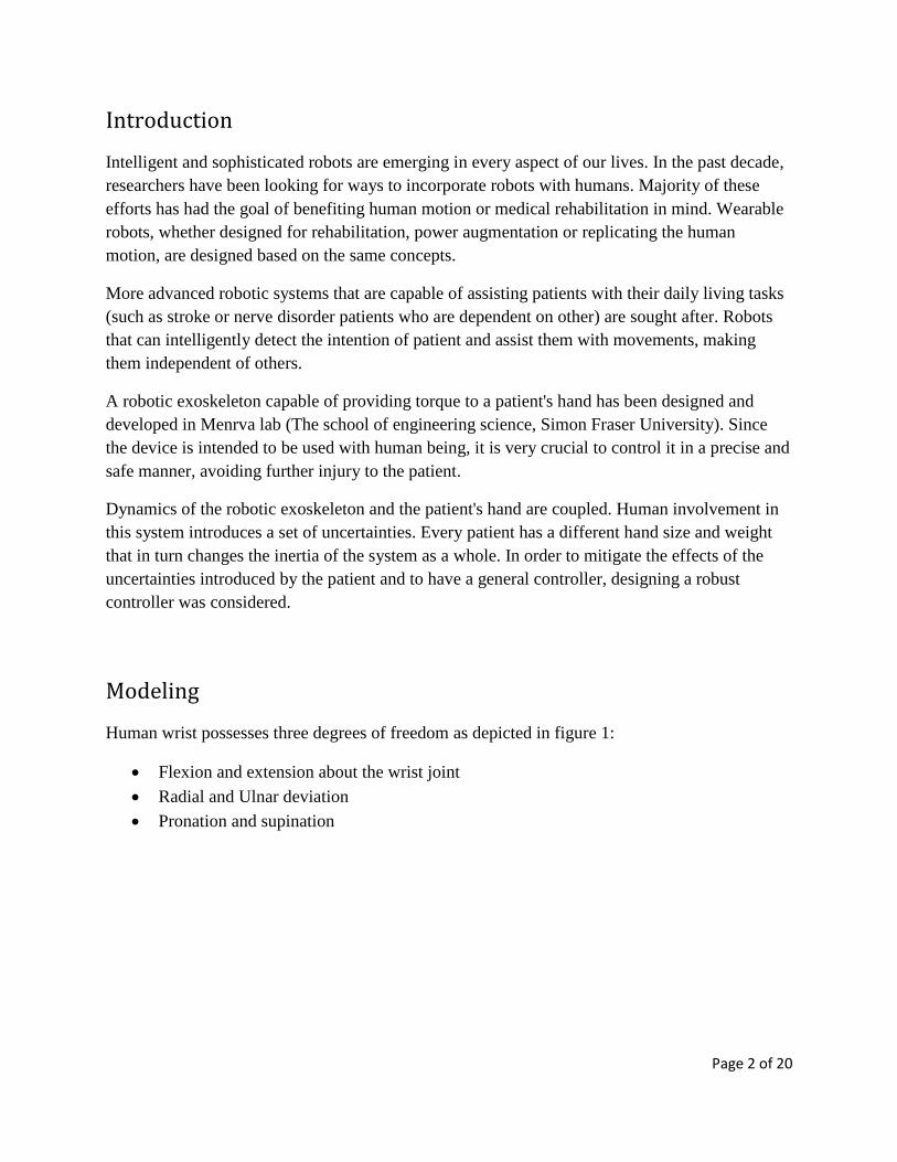
Human wrist possesses three degrees of freedom as depicted in figure 1:
Flexion and extension about the wrist joint
Radial and Ulnar deviation
Pronation and supination
Page 3 of 20
Figure 1- Human wrist degrees of freedom
http://www.revolutionarytennis.com/step12-5contact.html
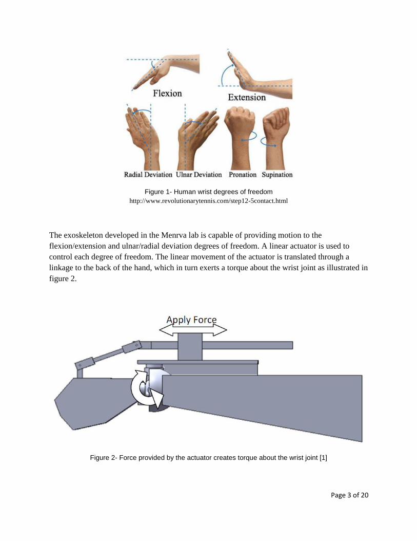
The exoskeleton developed in the Menrva lab is capable of providing motion to the
flexion/extension and ulnar/radial deviation degrees of freedom. A linear actuator is used to
control each degree of freedom. The linear movement of the actuator is translated through a
linkage to the back of the hand, which in turn exerts a torque about the wrist joint as illustrated in
figure 2.
Figure 2- Force provided by the actuator creates torque about the wrist joint [1]
Page 4 of 20
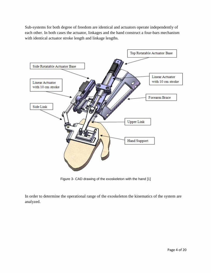
Sub-systems for both degree of freedom are identical and actuators operate independently of
each other. In both cases the actuator, linkages and the hand construct a four-bars mechanism
with identical actuator stroke length and linkage lengths.
Figure 3- CAD drawing of the exoskeleton with the hand [1]
In order to determine the operational range of the exoskeleton the kinematics of the system are
analyzed.
Page 5 of 20
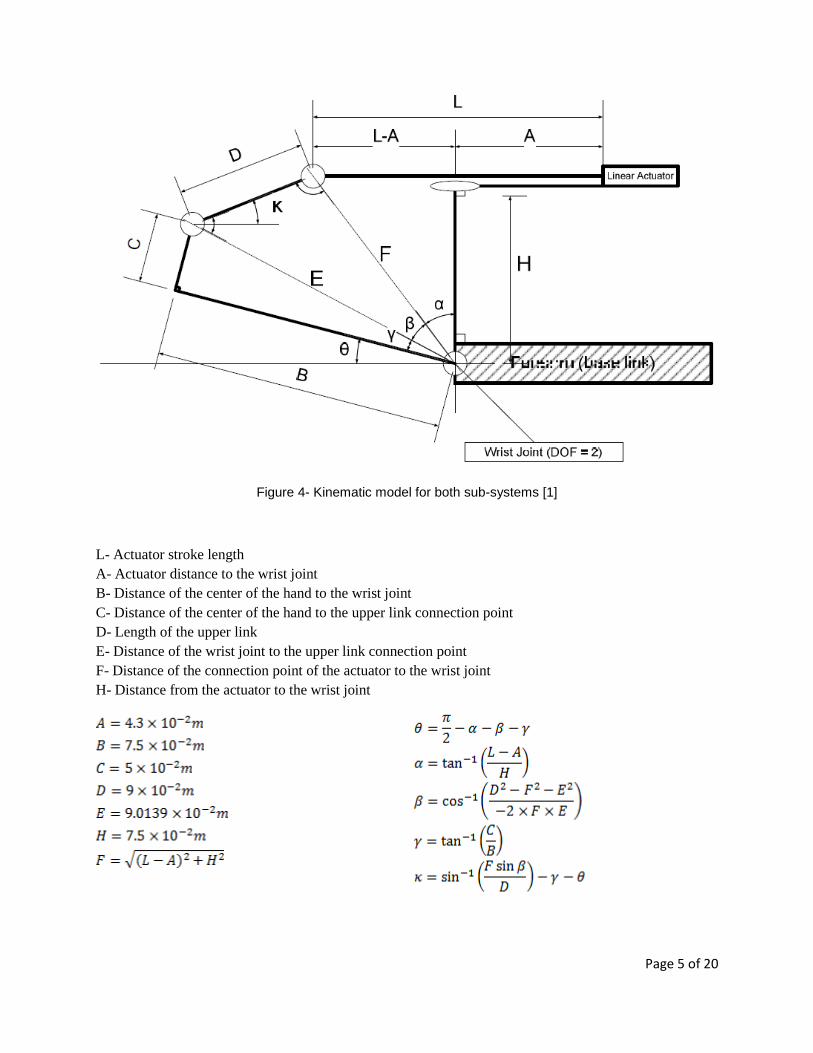
Figure 4- Kinematic model for both sub-systems [1]
L- Actuator stroke length
A- Actuator distance to the wrist joint
B- Distance of the center of the hand to the wrist joint
C- Distance of the center of the hand to the upper link connection point
D- Length of the upper link
E- Distance of the wrist joint to the upper link connection point
F- Distance of the connection point of the actuator to the wrist joint
H- Distance from the actuator to the wrist joint
Page 6 of 20
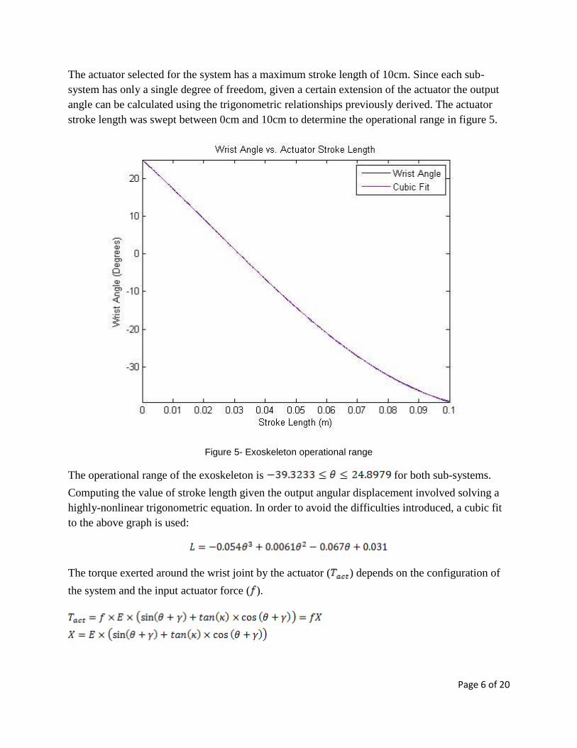
The actuator selected for the system has a maximum stroke length of 10cm. Since each sub-
system has only a single degree of freedom, given a certain extension of the actuator the output
angle can be calculated using the trigonometric relationships previously derived. The actuator
stroke length was swept between 0cm and 10cm to determine the operational range in figure 5.
Figure 5- Exoskeleton operational range
The operational range of the exoskeleton is for both sub-systems.
Computing the value of stroke length given the output angular displacement involved solving a
highly-nonlinear trigonometric equation. In order to avoid the difficulties introduced, a cubic fit
to the above graph is used:
The torque exerted around the wrist joint by the actuator ( ) depends on the configuration of
the system and the input actuator force ( ).
Page 7 of 20
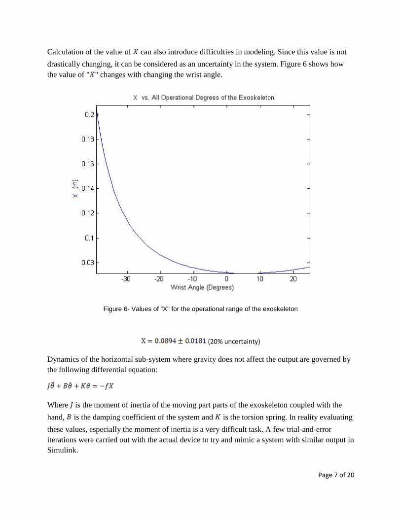
Calculation of the value of can also introduce difficulties in modeling. Since this value is not
drastically changing, it can be considered as an uncertainty in the system. Figure 6 shows how
the value of " " changes with changing the wrist angle.
Figure 6- Values of "X" for the operational range of the exoskeleton
(20% uncertainty)
Dynamics of the horizontal sub-system where gravity does not affect the output are governed by
the following differential equation:
Where is the moment of inertia of the moving part parts of the exoskeleton coupled with the
hand, is the damping coefficient of the system and is the torsion spring. In reality evaluating
these values, especially the moment of inertia is a very difficult task. A few trial-and-error
iterations were carried out with the actual device to try and mimic a system with similar output in
Simulink.
Page 8 of 20
Dynamics of the actuator were also taken into account. The actuator is unable to follow the input
current instantly and acts as a first-order lag system. The time constant of the actuator system
was also measured experimentally. The parameter " " equals " ".
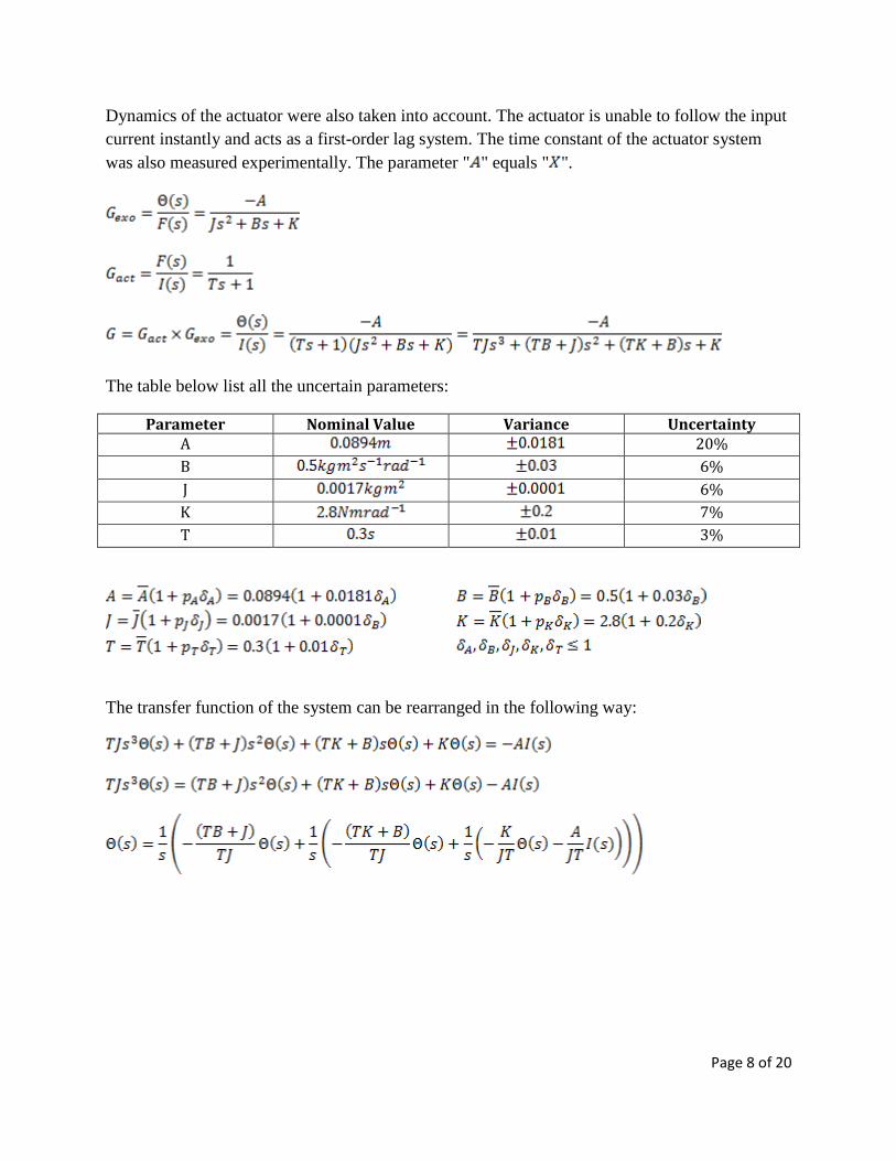
The table below list all the uncertain parameters:
Parameter Nominal Value Variance Uncertainty A 20%
B 6%
J 6%
K 7%
T 3%
The transfer function of the system can be rearranged in the following way:
Page 9 of 20
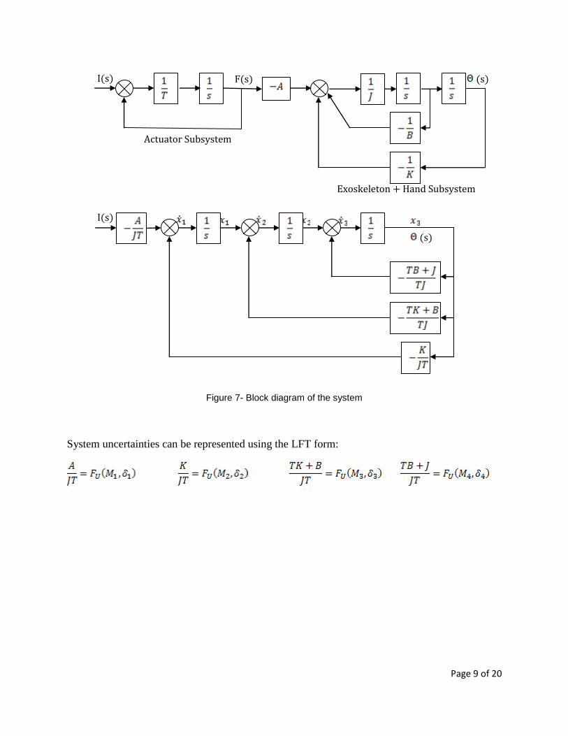
Figure 7- Block diagram of the system
System uncertainties can be represented using the LFT form:
I(s)
(s)
I(s) F(s) (s)
Actuator Subsystem
Exoskeleton + Hand Subsystem

Page 10 of 20
Figure 8- Block diagram of the system with the LFT blocks
I(s)
(s)

Page 11 of 20
Page 12 of 20
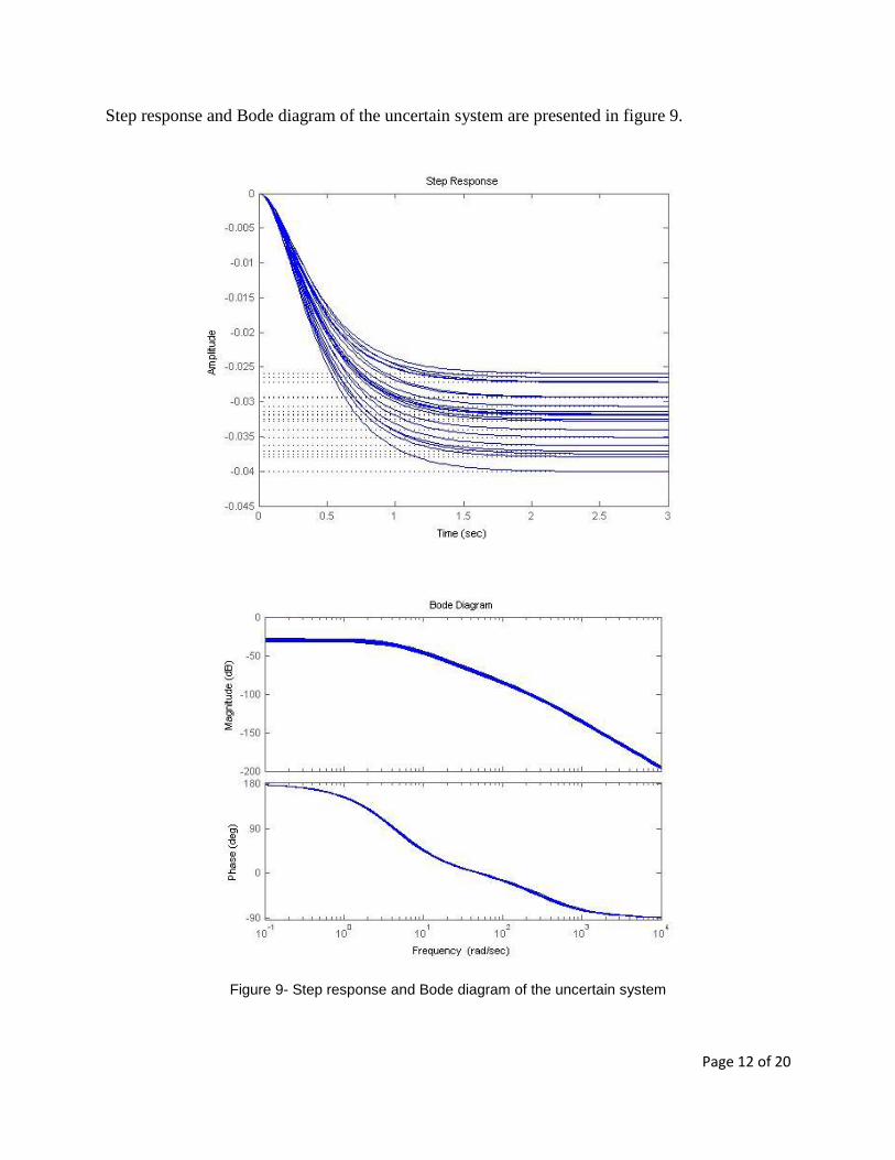
Step response and Bode diagram of the uncertain system are presented in figure 9.
Figure 9- Step response and Bode diagram of the uncertain system
Page 13 of 20
Controller Design
It is desirable to design a controller that satisfies the following condition:
Robust stability
Robust performance
Low-order
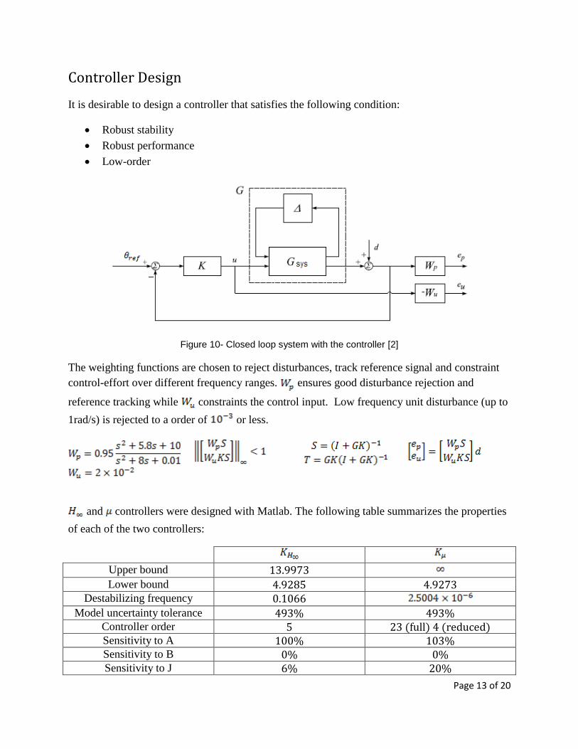
Figure 10- Closed loop system with the controller [2]
The weighting functions are chosen to reject disturbances, track reference signal and constraint
control-effort over different frequency ranges. ensures good disturbance rejection and
reference tracking while constraints the control input. Low frequency unit disturbance (up to
1rad/s) is rejected to a order of or less.
and controllers were designed with Matlab. The following table summarizes the properties
of each of the two controllers:
Upper bound 13.9973 Lower bound 4.9285 4.9273
Destabilizing frequency 0.1066 Model uncertainty tolerance 493% 493%
Controller order 5 23 (full) 4 (reduced) Sensitivity to A 100% 103% Sensitivity to B 0% 0% Sensitivity to J 6% 20%
Page 14 of 20
Sensitivity to K 5% 26% Sensitivity to T 1% 1%
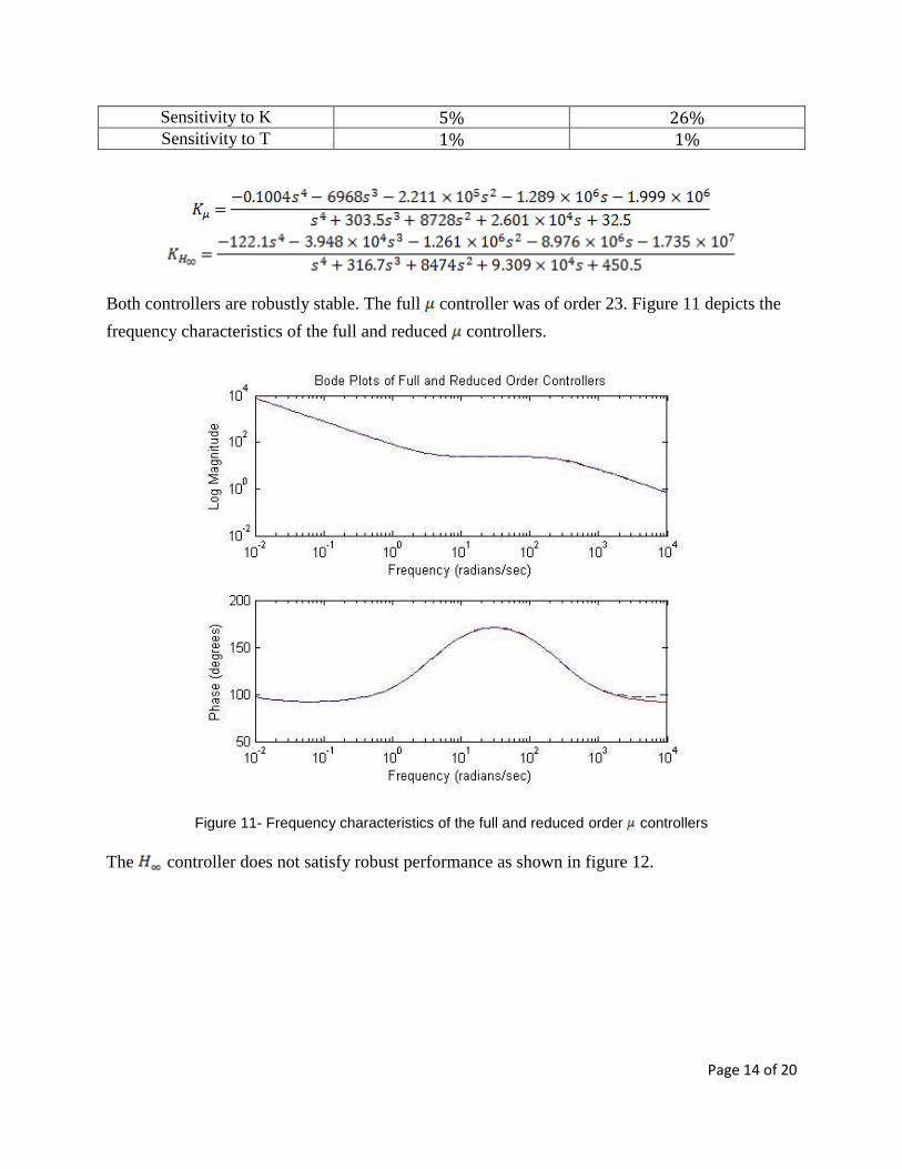
Both controllers are robustly stable. The full controller was of order 23. Figure 11 depicts the
frequency characteristics of the full and reduced controllers.
Figure 11- Frequency characteristics of the full and reduced order controllers
The controller does not satisfy robust performance as shown in figure 12.

Page 15 of 20
Figure 12 - Nominal and robust performance for the controller
Parameters resulting in the largest peak in the sensitivity function are computed as follows:
Figure 13 illustrates the closed loop response to a step reference signal for both controllers.
Figure 13 - Closed loop step response
Page 16 of 20
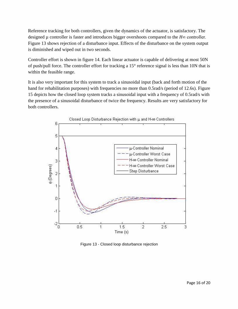
Reference tracking for both controllers, given the dynamics of the actuator, is satisfactory. The
designed µ controller is faster and introduces bigger overshoots compared to the H∞ controller.
Figure 13 shows rejection of a disturbance input. Effects of the disturbance on the system output
is diminished and wiped out in two seconds.
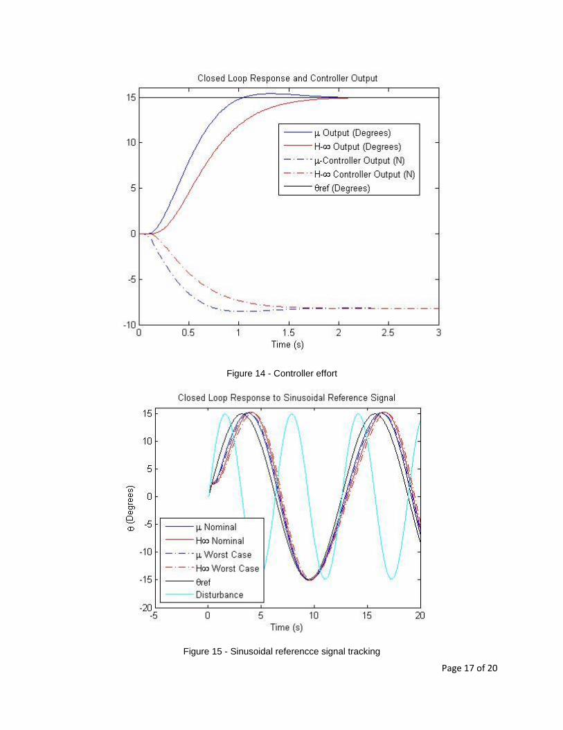
Controller effort is shown in figure 14. Each linear actuator is capable of delivering at most 50N
of push/pull force. The controller effort for tracking a 15° reference signal is less than 10N that is
within the feasible range.
It is also very important for this system to track a sinusoidal input (back and forth motion of the
hand for rehabilitation purposes) with frequencies no more than 0.5rad/s (period of 12.6s). Figure
15 depicts how the closed loop system tracks a sinusoidal input with a frequency of 0.5rad/s with
the presence of a sinusoidal disturbance of twice the frequency. Results are very satisfactory for
both controllers.
Figure 13 - Closed loop disturbance rejection
Page 17 of 20
Figure 14 - Controller effort
Figure 15 - Sinusoidal referencce signal tracking
Page 18 of 20
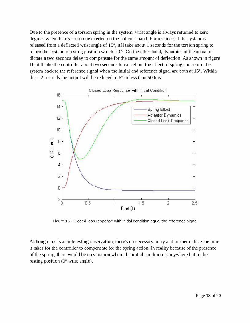
Due to the presence of a torsion spring in the system, wrist angle is always returned to zero
degrees when there's no torque exerted on the patient's hand. For instance, if the system is
released from a deflected wrist angle of 15°, it'll take about 1 seconds for the torsion spring to
return the system to resting position which is 0°. On the other hand, dynamics of the actuator
dictate a two seconds delay to compensate for the same amount of deflection. As shown in figure
16, it'll take the controller about two seconds to cancel out the effect of spring and return the
system back to the reference signal when the initial and reference signal are both at 15°. Within
these 2 seconds the output will be reduced to 6° in less than 500ms.
Figure 16 - Closed loop response with initial condition equal the reference signal
Although this is an interesting observation, there's no necessity to try and further reduce the time
it takes for the controller to compensate for the spring action. In reality because of the presence
of the spring, there would be no situation where the initial condition is anywhere but in the
resting position (0° wrist angle).
Page 19 of 20
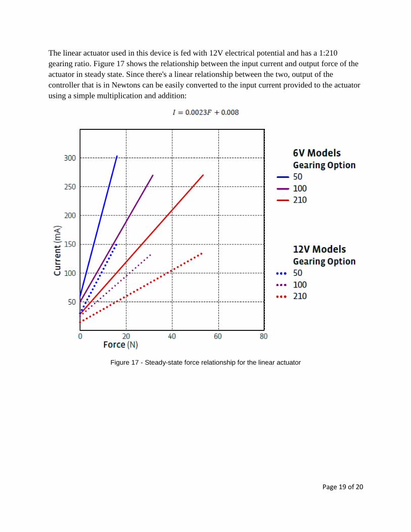
The linear actuator used in this device is fed with 12V electrical potential and has a 1:210
gearing ratio. Figure 17 shows the relationship between the input current and output force of the
actuator in steady state. Since there's a linear relationship between the two, output of the
controller that is in Newtons can be easily converted to the input current provided to the actuator
using a simple multiplication and addition:
Figure 17 - Steady-state force relationship for the linear actuator

Page 20 of 20
Conclusions & Future Work
Mechanics of a robotic hand exoskeleton were analyzed. Dynamics of the system consisting of
the linear actuator, exoskeleton and the patient's hand were modeled with uncertainties involved
in the application of the device.
Two controllers, based on the performance specifications imposed by two weighting functions
were designed. While both controllers guarantee robust stability, only the µ controller guarantees
robust performance. Closed loop time response characteristics of both controller were
satisfactory. The µ controller provides faster transient time responses with bigger overshoots
while the H∞ controller results in a more sluggish response with no overshoot in most cases.
Both controllers are of relative low order making their physical implementation feasible.
Next step to this project would be to implement the controller using a microcontroller in order to
control the device in real-time. The ultimate goal of this project would be to design a controller
that can satisfy robust stability and performance for a wide range of users with different hand
weights and dimensions.
References
[1] Zhen Gang Xiao, " CO-OP Work Report for ENSC 196", Menrva Lab, The School of
Engineering Science, Simon Fraser University, Summer 2009
[2] D.-W. Gu, P. Hr. Petkov and M. M. Konstantinov, "Robust Control Design with MATLAB",
Springer