american national standard evaluation of subsurface … · of the art, may be considered at the...
TRANSCRIPT

ANSI/ANS-2.17-20xx (Draft Rev. 11) May 26, 2010
DRAFT FOR NFSC BALLOT / PUBLIC REVIEW
American National Standard
Evaluation of Subsurface Radionuclide Transport at Commercial
Nuclear Power Production Facilities
Secretariat American Nuclear Society Prepared by the American Nuclear Society Standards Committee Working Group ANS-2.17 Published by the American Nuclear Society 555 North Kensington Avenue La Grange Park, Illinois 60526 USA Approved Month DD, 201X by the American National Standards Institute, Inc.

i
American National Standard
Designation of this document as an American National Standard attests that the principles of openness and due process have been followed in the approval procedure and that a consensus of those directly and mate-rially affected by the standard has been achieved. This standard was developed under the procedures of the Standards Committee of the American Nuclear Society; these procedures are accredited by the American National Standards Institute, Inc., as meeting the criteria for American National Standards. The consensus committee that approved the standard was ba-lanced to ensure that competent, concerned, and varied interests have had an opportunity to participate. An American National Standard is intended to aid industry, consumers, governmental agencies, and general interest groups. Its use is entirely voluntary. The existence of an American National Standard, in and of it-self, does not preclude anyone from manufacturing, marketing, purchasing, or using products, processes, or procedures not conforming to the standard. By publication of this standard, the American Nuclear Society does not insure anyone utilizing the standard against liability allegedly arising from or after its use. The content of this standard reflects acceptable prac-tice at the time of its approval and publication. Changes, if any, occurring through developments in the state of the art, may be considered at the time that the standard is subjected to periodic review. It may be reaf-firmed, revised, or withdrawn at any time in accordance with established procedures. Users of this standard are cautioned to determine the validity of copies in their possession and to establish that they are of the lat-est issue. The American Nuclear Society accepts no responsibility for interpretations of this standard made by any individual or by any ad hoc group of individuals. Requests for interpretation should be sent to the Standards Department at Society Headquarters. Action will be taken to provide appropriate response in accordance with established procedures that ensure consensus on the interpretation. Comments on this standard are encouraged and should be sent to Society Headquarters.
Published by American Nuclear Society 555 North Kensington Avenue La Grange Park, Illinois 60526 USA Copyright © 201X by American Nuclear Society. All rights reserved. Any part of this standard may be quoted. Credit lines should read “Extracted from American National Standard
ANSI/ANS-2.17-201X with permission of the publisher, the American Nuclear Society.” Reproduction prohibited under
copyright convention unless written permission is granted by the American Nuclear Society.
Printed in the United States of America
ii
Foreword (This Foreword is not a part of American National Standard “Evaluation of Subsurface Radionuclide Transport at Com-
mercial Nuclear Power Production Facilities”, ANSI/ANS-2.17-201X.)
This standard constitutes a major revision of the original standard, ANSI/ANS-2.17-1980, which was adopted on April 9, 1980, reaffirmed on October 3, 1989, and with-drawn on July 28, 2000. A new working group, Working Group ANS-2.17 of ANS-25 Subcommittee (Siting: Environmental & Emergency Preparedness) of the American Nuclear Standards Committee, was constituted November 2005 to revise the original standard.
This standard might reference documents and other standards that have been superseded or withdrawn at the time the standard is applied. A statement has been included in the references section that provides guidance on the use of references. This standard mentions, but does not exhaustively describe, the concepts of generating risk-informed insights, performance-based requirements, and a graded approach to qual-ity assurance. The user is advised that one or more of these techniques could enhance the application of this standard. Two appendices are provided to assist practitioners who would implement the guidance in this standard. Appendix A provides information on relevant U.S. Nuclear Regulatory Commission regulatory criteria and guidance, and its Table A provides a listing of stan-dard documents (e.g., ANS, ASTM, ISO, etc) for conducting subsurface radionuclide transport characterization, monitoring, and modeling programs. Appendix B provides tables that summarize information and parameters identified in the guidance.

iii
The ANS-2.17 Working Group of the Standards Committee of the American Nuclear Society had the fol-lowing membership:
J. S. Bollinger (Co-Chair), Savannah River National Laboratory T. C. Rasmussen (Co-Chair), University of Georgia M. J. Barvenik, GZA GeoEnvironmental, Inc. R. L. Beauheim, Sandia National Laboratories G. S. Bodvarsson1, Lawrence Berkeley National Laboratory J. M. Godfrey, Southern Nuclear Company D. Goswami, Washington State Department of Ecology V. Guvanasen, HydroGeoLogic, Inc. C. D. Martinec, Duke Energy P. D. Meyer, Pacific Northwest National Laboratory F. J. Molz, III, Clemson University T. J. Nicholson, U.S. Nuclear Regulatory Commission D. Scott, Radiation Safety and Control Services, Inc. E. P. Weeks, U.S. Geological Survey D. G. Wells, Washington Savannah River Company M. H. Young, Desert Research Institute
This standard was prepared under the guidance of Subcommittee ANS-25, Siting: Environmental & Emergency Preparedness, of the American Nuclear Society. At the time of the ballot, Subcommittee ANS-25 was composed of the following members:
K. R. Bryson (Chair), Shaw Environmental, Inc. C. A. Mazzola (Vice Chair), Shaw Environmental, Inc. J. S. Bollinger, Savannah River National Laboratory C. Costantino, Individual A. N. Findikakis, Bechtel Corporation C. Guggino, Bechtel Corporation D. Hang, Individual K. Hanson, AMEC Geomatrix J. J. Litehiser, Bechtel Corporation T. C. Rasmussen, University of Georgia J. D. Stevenson, Individual L. W. Vail, Pacific Northwest National Laboratory S. A. Vigeant, Shaw Environmental & Infrastructure
1 The working group would like to gratefully acknowledge the contributions by G.S. “Bo” Bodvarsson, who died
prior to the completion of this standard.

iv
The standard was processed and approved for submittal to ANSI by the Nuclear Facilities Standards Committee (NFSC) of the American Nuclear Society. Committee approval of the standard does not nec-essarily imply that all members voted for approval. At the time it approved this standard the NFSC had the following membership:
C. A. Mazzola (Chair), Shaw Environmental & Infrastructure, Inc. R. M. Ruby (Vice Chair), Constellation Energy J. K. August, CORE, Inc. W. H. Bell, South Carolina Electric & Gas Company J. R. Brault, Shaw MOX Project C. K. Brown, Southern Nuclear Operating Company R. H. Bryan, Tennessee Valley Authority K. R. Bryson, Shaw Environmental, Inc. C. E. Carpenter, U.S. Nuclear Regulatory Commission T. Dennis, Individual D. R. Eggett, Automated Engineering Services Corporation R. W. Englehart, Individual P. Guha, U.S. Department of Energy R. Hall, Exelon Generation Company, LLC P. S. Hastings, Duke Energy R. A. Hill, ERIN Enginneering and Research, Inc. N. P. Kadambi, Individual E. M. Lloyd, Exitech Corporation E. P. Loewen, General Electric S. A. Lott, Los Alamos National Laboratory J. E. Love, Bechtel Power Corporation R. H. McFetridge, Westinghouse Electric Corporation C. H. Moseley, ASME/NQA Liaison (BWXT Y-12) D. G. Newton, AREVA NP W. N. Prillaman, AREVA NP W. B. Reuland, Individual D. J. Spellman, Oak Ridge National Laboratory S. L. Stamm, Shaw Nuclear Services J. D. Stevenson, Individual J. A. Wehrenberg, Southern Nuclear Operating Company M. J. Wright, Entergy Operations, Inc.
v
Contents Section Page
1.0 SCOPE 1
2.0 DEFINITIONS 2
2.1 Acronyms and Initialisms 2 2.2 Definition of Terms 2
3.0 PERFORMANCE ASSESSMENT METHODOLOGY 9
3.1 Performance Assessment Activities 9 3.2 Performance Assessment Elements 12
4.0 SITE CHARACTERIZATION 15
4.1 Conceptual Site Model 15 4.2 Facilities Characterization 17 4.3 Hydrogeologic Characterization 18
5.0 MATHEMATICAL MODELING 23
5.1 Model Scope 23 5.2 Calibration, Prediction, and Updating 26 5.3 Uncertainty Assessment 28
6.0 PERFORMANCE-CONFIRMATION MONITORING 30
6.1 Types of Monitoring Data 30 6.2 Monitoring Methods 31 6.3 Monitoring Locations and Frequencies 32
7.0 INFORMATION MANAGEMENT 34
7.1 Characterization and Monitoring Data Management 34 7.2 Mathematical Model Management 35
8.0 REFERENCES 37
APPENDIX A. CONSULTATION AND COORDINATION 42
APPENDIX B. SUMMARY OF INFORMATION AND PARAMETERS 46
1
Evaluation of Subsurface Radionuclide Transport at Com-1
mercial Nuclear Power Production Facilities 2
1.0 Scope 3
This national standard establishes the requirements for evaluating the occurrence and movement of radio-4
nuclides in the subsurface resulting from abnormal radionuclide releases at commercial nuclear power 5
production facilities. 6
This standard applies to abnormal radionuclide releases that affect groundwater, water supplies derived 7
from groundwater, and surface waters affected by subsurface transport, including exposure pathways 8
across the groundwater-surface water transition zone. 9
This standard does not apply to: 10
Subsurface occurrence and movement of non-radioactive materials, other than as indicators of 11
subsurface radionuclide occurrence and movement in soil and groundwater; 12
Surface occurrence and movement of radionuclides, except to the extent that surface radionuclide 13
occurrence and movement may affect, or be affected by, onsite subsurface radionuclide occur-14
rence and movement (e.g., a surface release that subsequently infiltrates and affects groundwater, 15
a subsurface release that affects surface water, including exposure pathways across the groundwa-16
ter-surface water transition zone); 17
Corrective action, which may be required as the result of a subsurface radionuclide release; and 18
Dose calculations to demonstrate compliance with any regulatory requirement. 19
20

2
2.0 Definitions 1
2.1 Acronyms and Initialisms 2
ALARA: As Low As Is Reasonably Achievable 3
ANS: American Nuclear Society 4
ANSI: American National Standards Institute 5
ASTM: ASTM International, previously known as the American Society for Testing and Materials 6
CFR: Code of Federal Regulations 7
CRWMS: Civilian Radioactive Waste Management System Management and Operating Contractor 8
CSM: Conceptual Site Model 9
DQOs: Data Quality Objectives 10
EIS: Environmental Impact Statement 11
EPRI: Electric Power Research Institute 12
FEPs: Features, Events, and Processes 13
IAEA: International Atomic Energy Association 14
NEI: Nuclear Energy Institute 15
NGWA: National Ground Water Association 16
NRC: National Research Council 17
REMP: Radiological Environmental Monitoring Programs 18
RETS: Radioactive Effluent Technical Specifications 19
TEDE: Total Effective Dose Equivalent 20
U.S.: United States 21
USEPA: U.S. Environmental Protection Agency 22
USNRC: U.S. Nuclear Regulatory Commission 23 2.2 Definition of Terms 24
Abnormal radionuclide release: An unplanned or uncontrolled release of licensed radioactive material, 25
3
including leaks and spills to the site environs (e.g., locations outside of nuclear power plant systems, 1
structures, and components), which may be undetected at the time of the original release. 2
As low as is reasonably achievable (ALARA): Every reasonable effort is made to maintain exposures to 3
radiation as far below the dose limits as is practical consistent with the purpose for which the licensed ac-4
tivity is undertaken, taking into account the state of technology, the economics of improvements in rela-5
tion to state of technology, the economics of improvements in relation to benefits to the public health and 6
safety, and other societal and socioeconomic considerations, and in relation to utilization of nuclear ener-7
gy and licensed materials in the public interest. 8
Ambient flow: Natural horizontal or vertical groundwater movement through the subsurface; or resulting 9
from natural hydraulic gradients in an open borehole, well or piezometer. 10
Aquifer: A geologic formation, group of formations, or part of a formation that contains sufficient satu-11
rated permeable material to yield significant quantities of water to springs, seeps, and wells. 12
Aquifer, confined: An aquifer bounded above by an aquitard. 13
Aquifer, unconfined: An aquifer whose upper surface is a water table. 14
Aquitard: A geologic formation that restricts, but does not prevent, groundwater movement into or be-15
tween aquifers. 16
Baseline concentration, local: The concentration or activity of a substance that is indicative of local site 17
conditions prior to the operation of the nuclear facility. 18
Baseline concentration, regional: The concentration or activity of a substance that is indicative of re-19
gional conditions prior to the operation of the nuclear facility. 20
Biogeochemical processes: The chemical interactions that exist between the atmosphere, hydrosphere, 21
lithosphere, and biosphere. 22
Capillary zone: The region above the water table where pores are saturated, but the water gage pressure 23
is negative; also called the tension-saturated zone. 24
Conceptual site model (CSM): An abstract, qualitative representation of the relevant flow and transport 25
FEPs that affect subsurface radionuclide transport at the site. The CSM is best presented as a set of two-26
dimensional graphics (plan and profile) or a three-dimensional graphic (isometric), which qualitatively 27
present the interrelationships between the FEPs, along with supporting text. 28
Confining layer: A geologic unit within the saturated or unsaturated zones that has a distinctly lower hy-29
4
draulic conductivity than the underlying and overlying geologic units; also called an aquitard when in the 1
saturated zone. 2
Contamination: Occurrence of material in a location where it is not considered indigenous to its sur-3
roundings. 4
Corrective action: Activities undertaken to manage or remediate the occurrence or movement of subsur-5
face radionuclides. 6
Critical outcome: A long-term, strategic goal, stated in terms of the expected results, that captures the 7
essence of the desired end state to be achieved. 8
Data quality objectives (DQOs): Qualitative and quantitative statements derived from the DQO process 9
that clarify the study objectives, define the most appropriate type of data to collect, determine the most 10
appropriate conditions from which to collect the data, and specify tolerable limits on decision error rates. 11
Because DQOs will be used to establish the quality and quantity of data needed to support decisions, they 12
should encompass the total uncertainty resulting from all data collection activities, including analytical 13
and sampling activities. 14
Data quality objective process: A systematic, strategic-planning tool based on the scientific method that 15
identifies and defines the type, quality, and quantity of data needed to satisfy a specified use. DQOs are 16
the qualitative and quantitative outputs from the DQO process. 17
Dual porosity model: A flow and transport model applied to a porous medium composed of two porosity 18
fractions or domains. One fraction stores and transmits solute (mobile flow domain), while the second 19
fraction only stores solute (immobile domain). Fluid and solute exchange between the mobile and immo-20
bile domains occur as functions of the hydraulic head and concentration gradient between the two, respec-21
tively. 22
Effluent concentration limit: The concentration values (given in Columns 1 and 2 of Table 2 in 10 CFR 23
Part 20, Appendix B) equivalent to the radionuclide concentrations which, if inhaled or ingested conti-24
nuously over the course of a year, would produce a total effective dose equivalent of 0.05 rem (50 milli-25
rem or 0.5 millisieverts). 26
Effluent discharge (radioactive): Any outflow in which plant-related, licensed radioactive material is 27
released from a system, structure, or component and enters the unrestricted area. 28
Engineered barrier: A man-made cover, wall, or device used to prevent fluid flow or contaminant mi-29
gration. 30
5
Exposure pathway: A mechanism by which radioactive material is transferred from the (local) environ-1
ment to humans. There are three commonly recognized exposure pathways; inhalation, ingestion, and di-2
rect radiation. For example, ingestion is an exposure pathway, and it may include dose contributions from 3
one or more routes of exposure. For example, one route of exposure that may contribute to the ingestion 4
exposure pathway is often referred to as grass-cow-milk-infant-thyroid route of exposure. 5
Features, events, and processes (FEP): An assessment of the relevant: 1) Features, which are identified 6
physical characteristics of the total system, and how they behave over time; 2) Events, which are occur-7
rences of abnormal radionuclide releases; and 3) Processes, which include physical, chemical, and biolog-8
ical processes that govern radionuclide transport. 9
Flux: The volumetric or mass discharge per unit cross-sectional area of medium (solids plus pores); 10
called the Darcian flux when applied to water movement. 11
Groundwater: All water contained in pores, fractures or voids at or below the water table (also called 12
the phreatic surface); also identifies water in the phreatic zone.2 13
Groundwater recharge: The process involved in the addition of water to the phreatic zone; also, the 14
amount of water added to the saturated zone. 15
Hydraulic gradient: The change in hydraulic head with distance. 16
Hydraulic head: One of several measures of the energy content of water (in this case, energy per unit 17
weight), expressed as a height of freshwater above a datum. In fresh groundwater, the hydraulic head is 18
commonly found using the water surface elevation in an open borehole, well, or piezometer. 19
Hydrostratigraphy: A conceptual framework that classifies geologic materials of considerable lateral 20
extent into reasonably distinct hydrologic systems. 21
Infiltration: The movement of water from above the ground surface into the vadose zone. 22
Intermediate point of compliance: A location used as a reference point for the purpose of protecting the 23
groundwater resource, where there are no immediate existing receptors but where contamination is re-24
garded as undesirable. 25
Mathematical model: A quantitative representation of the relevant flow and transport FEPs that affect 26
2 Regulatory agencies and industry may consider groundwater to include all subsurface water, so that all contami-
nants in the subsurface are evaluated, and not only those in the phreatic zone.

6
subsurface radionuclide transport at the site. The mathematical model can be an algebraic equation for 1
simple, homogeneous systems, or it can be a computer model in more complicated systems. 2
Normal radionuclide release: The known, planned, or approved release of radionuclides to the environ-3
ment, including controlled releases of low-level radioactive materials. 4
Perched water: Subsurface water collecting on low-permeability geologic materials that are separated 5
from an underlying main body of groundwater by an unsaturated zone. Water located above the water ta-6
ble whose water gage pressure is greater than zero. 7
Performance assessment: A systematic analysis that addresses the types and likelihood of abnormal ra-8
dionuclide releases, their resulting impacts, and how these impacts compare to regulatory standards. 9
Performance-based regulation: Regulations that are outcome-oriented rather than procedure-oriented. 10
An approach to regulatory practice that establishes performance and results as the primary bases for deci-11
sion making. Performance-based regulations have the following attributes: (1) measurable, calculable or 12
objectively observable parameters exist or can be developed to monitor performance; (2) objective criteria 13
exist or can be developed to assess performance; (3) licensees have flexibility to determine how to meet 14
the established performance criteria in ways that will encourage and reward improved outcomes; and (4) a 15
framework exists or can be developed in which the failure to meet a performance criterion, while undesir-16
able, will not in and of itself constitute or result in an immediate safety concern. 17
Performance indicator: An observable hydrologic (e.g., water content, water flux, water quality parame-18
ter) or radiologic (e.g., tritium) parameter, the value (or change in value) of which is used to determine 19
whether a performance objective is achieved. 20
Performance objective: A targeted outcome or goal desired to achieve a successful end result (e.g., a 21
goal to meet a defined level of environmental quality). 22
Performance threshold: A quantitative criterion for each performance indicator that defines when per-23
formance objectives are, or are not being, met. 24
Phreatic zone: The region below the water table where water gage pressure is greater than or equal to ze-25
ro. 26
Porosity: The ratio of the volume of pores, fractures, or voids in soil or rock to the total volume (solid 27
plus pore volumes). 28
Receptor: An individual located outside of the controlled area (e.g., offsite) that may receive a radionuc-29
lide exposure via subsurface transport. 30
7
Restricted area: An area, access to which is limited by the licensee for the purpose of protecting individ-1
uals against undue risks from exposure to radiation and radioactive materials. Restricted area does not in-2
clude areas used as residential quarters, but separate rooms in a residential building may be set apart as a 3
restricted area. 4
Risk-informed approach: An approach to regulatory decision-making represents a philosophy whereby 5
risk insights are considered together with other factors to establish requirements that better focus licensee 6
and regulatory attention on design and operational issues commensurate with their importance to health 7
and safety. This approach enhances the traditional approach by: (a) allowing explicit consideration of a 8
broader set of potential challenges to safety, (b) providing a logical means for prioritizing these chal-9
lenges based on risk significance, operating experience, and/or engineering judgment, (c) facilitating con-10
sideration of a broader set of resources to defend against these challenges, (d) explicitly identifying and 11
quantifying sources of uncertainty in the analysis, and (e) leading to better decision-making by providing 12
a means to test the sensitivity of the results to key assumptions. Where appropriate, a risk-informed regu-13
latory approach can also be used to reduce unnecessary conservatism in deterministic approaches, or can 14
be used to identify areas with insufficient conservatism and provide the bases for additional requirements 15
or regulatory actions. 16
Risk factors: Parameters related to a radiological risk assessment; e.g., proximity of a member of a pub-17
lic to a facility with subsurface contamination, interconnection between an aquifer and the facility’s sub-18
surface contamination, groundwater transport rates, direction of flow, dilution factors from local surface 19
water bodies and/or groundwater flow, etc. 20
Route of exposure: A specific scenario by which radioactive material may be transferred from the envi-21
ronment to an individual or human receptor causing an exposure. For the ingestion exposure pathway, the 22
routes of exposure could include the ingestion of leafy vegetables, milk, water, fish, etc. 23
Saturated zone: The zone in the subsurface where the pores are filled with water (phreatic zone plus ca-24
pillary zone). 25
Shall, should, and may: The word “shall” is used to denote a requirement; the word “should” is used to 26
denote a recommendation; and the word “may” is used to denote permission, neither a requirement nor a 27
recommendation. 28
Soil water potential: A measure of the energy content of water in unsaturated materials, the spatial gra-29
dient of which causes soil water movement. The energy content is the sum of gravitational, pressure, os-30
motic, and other forces. 31
8
Spatially explicit data: Attributes that can be geo-referenced to a specific location. 1
Subsurface: All rock, soil, and fill material below the ground surface. 2
Subsurface water: Water contained in pores and voids within geologic media below the ground surface. 3
Sum-of-the-fractions rule: Calculated by dividing each nuclide's concentration by the appropriate limit 4
and adding the resulting values. The appropriate limits must all be taken from the same column of the 5
same table in 10 CFR part 61.55. The sum of the fractions for the column must be less than one if the 6
waste class is to be determined by that column. 7
System: In the context of this standard, the system consists of: 1) all facilities from which a release to the 8
groundwater could occur; 2) all facility policies or procedures that may impact or cause a release; 3) the 9
man-machine interface of a facility that may cause or contribute to a release; 4) all engineered barriers 10
and leak detection systems; 5) the local and regional hydrogeology; and 6) all monitoring well networks 11
and procedures for gathering and analyzing soil and groundwater samples. 12
Unity rule: Used to determine whether the sum of the ratios of the quantity of each isotope to the appli-13
cable value in 10 CFR part 20, Appendix B, is greater than one. 14
Unrestricted area: An area, access to which is neither limited nor controlled by the licensee. 15
Unsaturated zone: A subsurface region where pores are filled partially with water and partially with air; 16
most commonly, the zone between the ground surface and the top of the capillary zone. 17
Vadose zone: A subsurface region where the water gage pressure is negative; most commonly, the zone 18
between the ground surface and the water table. 19
Water table: The water surface in an unconfined aquifer corresponding to where the water gage pressure 20
is zero, also called the phreatic surface. 21
22

9
3.0 Performance Assessment Methodology 1
A graded, risk-informed, performance-assessment methodology shall be used for evaluating the effects of 2
subsurface radionuclide transport. The graded risk-informed approach allows risk, derived from accident 3
probability and consequences, to be used to optimize the use of resources while achieving a high level of 4
safety3. The performance assessment shall be based on the complexity of geologic and hydrologic condi-5
tions, the types of radioactive materials and facility components present at the site, the types and effec-6
tiveness of engineered and natural barriers, and the proximity to surface water and groundwater recep-7
tors.4 8
3.1 Performance Assessment Activities 9
Performance assessment is used in this ANSI standard to prescribe site characterization, mathematical 10
modeling, and performance-confirmation monitoring. The goal is to understand and describe the relevant 11
geologic, hydrologic, physical, biological, and chemical processes that significantly affect subsurface ra-12
dionuclide transport. Performance assessment is used to develop and evaluate alternative site characteri-13
zation, monitoring, and modeling strategies, with the objective of providing data and information that is 14
used to demonstrate whether system design or regulatory requirements have been met. 15
16
3 The performance-assessment methodology may be used to demonstrate regulatory compliance where the basis
for compliance is a risk level. In this case, probabilities may be determined from statistical data or reasonable es-timates based on failure analyses of the facility.
4 For example, a facility with a less-significant radionuclide source term, minor subsurface contamination, simple or well-understood hydrogeology, or having limited effects on groundwater resources, generally requires less ex-tensive site characterization, mathematical modeling, and performance-confirmation monitoring than a facility with significant subsurface contamination that has the potential to exceed national radiation protection standards.
10
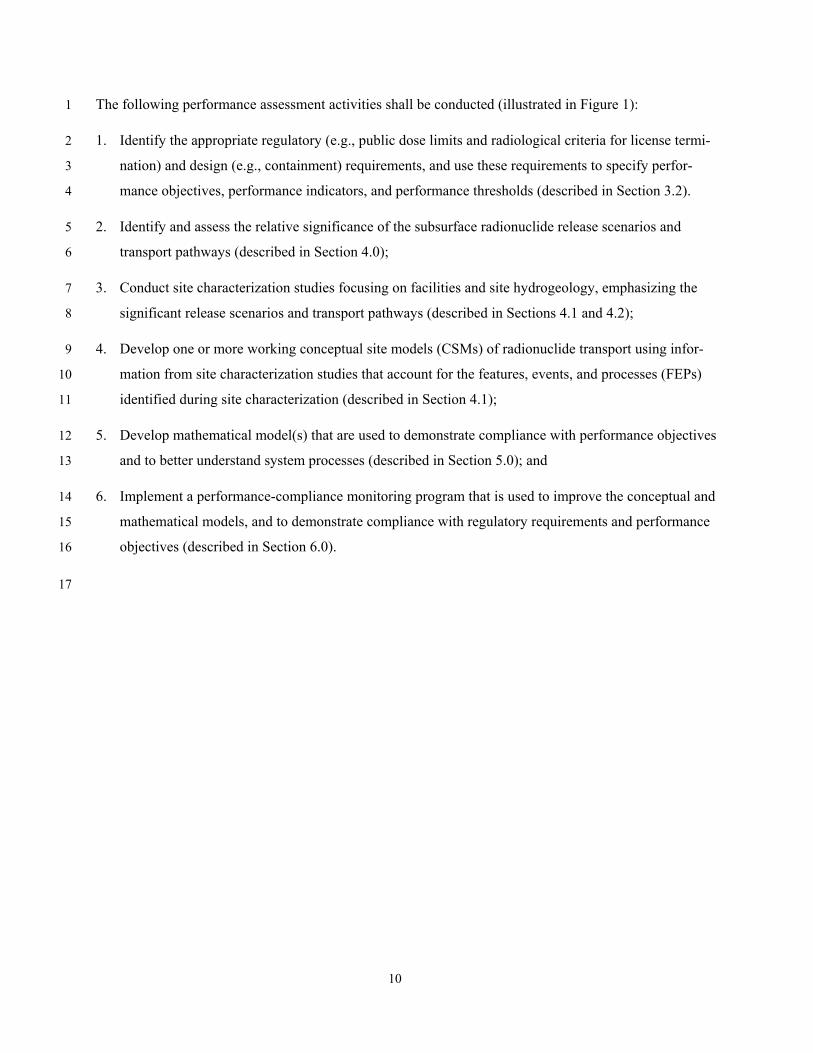
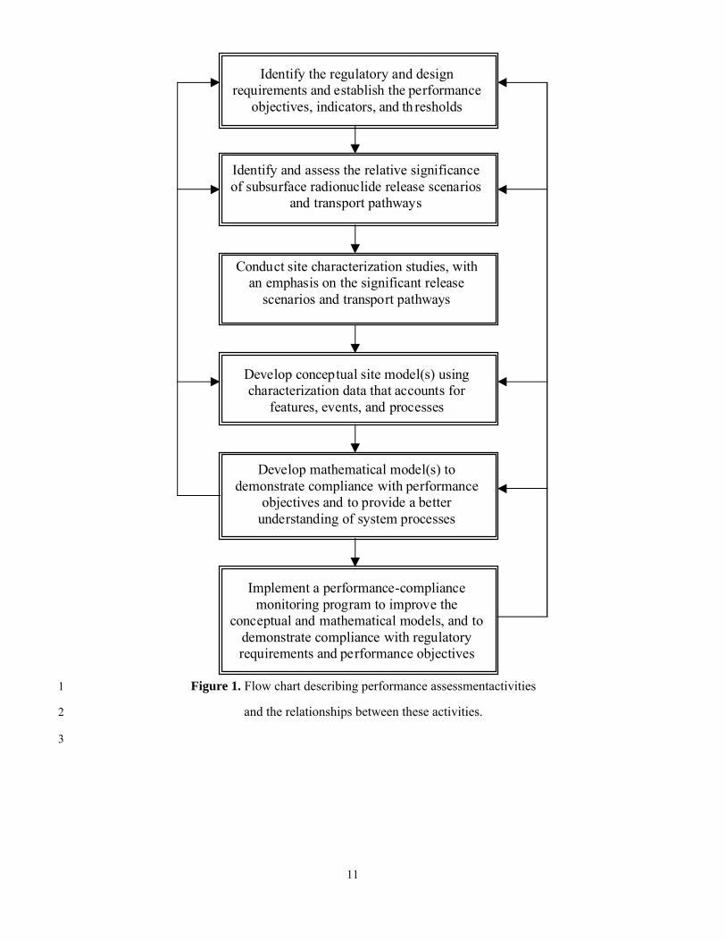
The following performance assessment activities shall be conducted (illustrated in Figure 1): 1
1. Identify the appropriate regulatory (e.g., public dose limits and radiological criteria for license termi-2
nation) and design (e.g., containment) requirements, and use these requirements to specify perfor-3
mance objectives, performance indicators, and performance thresholds (described in Section 3.2). 4
2. Identify and assess the relative significance of the subsurface radionuclide release scenarios and 5
transport pathways (described in Section 4.0); 6
3. Conduct site characterization studies focusing on facilities and site hydrogeology, emphasizing the 7
significant release scenarios and transport pathways (described in Sections 4.1 and 4.2); 8
4. Develop one or more working conceptual site models (CSMs) of radionuclide transport using infor-9
mation from site characterization studies that account for the features, events, and processes (FEPs) 10
identified during site characterization (described in Section 4.1); 11
5. Develop mathematical model(s) that are used to demonstrate compliance with performance objectives 12
and to better understand system processes (described in Section 5.0); and 13
6. Implement a performance-compliance monitoring program that is used to improve the conceptual and 14
mathematical models, and to demonstrate compliance with regulatory requirements and performance 15
objectives (described in Section 6.0). 16
17
11
Figure 1. Flow chart describing performance assessmentactivities 1
and the relationships between these activities. 2
3
Identify the regulatory and designrequirements and establish the performance
objectives, indicators, and th resholds
Identify and assess the relative significanceof subsurface radionuclide release scenarios
and transport pathways
Conduct site characterization studies, withan emphasis on the significant release
scenarios and transport pathways
Develop conceptual site model(s) usingcharacterization data that accounts for
features, events, and processes
Implement a performance-compliancemonitoring program to improve the
conceptual and mathematical models, and todemonstrate compliance with regulatoryrequirements and performance objectives
Develop mathematical model(s) todemonstrate compliance with performance
objectives and to provide a betterunderstanding of system processes

12
3.2 Performance Assessment Elements 1
The performance assessment is structured such that the following elements are required: 2
1. Performance objectives shall be established for all regulatory and design requirements6. Separate per-3
formance objectives for onsite7 and offsite8 areas shall be established. It is acceptable to establish per-4
formance objectives that are more stringent than regulatory requirements if greater risk factors are 5
present. 6
2. Performance indicators shall be defined for the purpose of establishing whether the performance ob-7
jective has, or has not, been met. An ideal performance indicator is one that unambiguously deter-8
mines whether a performance objective is being met. If different pathways exhibit different transport 9
and exposure risks, then separate performance indicators (and thresholds) shall be developed for these 10
pathways.9 Table 1 presents a ranked list of radionuclides at commercial nuclear facilities, and may 11
be appropriate performance indicators, but those selected may differ depending upon site-specific 12
structures, systems and components (e.g., spent-fuel pool, radwaste tank, condensate tank, effluent-13
transfer pipes, etc.), their associated radionuclide inventories, and transport characteristics. Appropri-14
ate consideration shall be given for identifying normal radionuclide concentrations that result from 15
routine operations. 16
17
6 Potentially relevant regulatory requirements are provided in Appendix A. 7 For example, onsite dose limits include the 10 CFR 20.1402 license termination criteria of ≤ 25 mrem/yr (unre-
stricted use). 8 For example, offsite public dose limits include the USNRC limit of 100 mrem/yr (all pathways), USEPA 40 CFR
141.66 limit of 4 mrem/yr (drinking-water pathway), and 10 CFR 50, Appendix I numerical guides for design objectives and limiting conditions for operation of ≤3 mrem/yr (to a real individual using realistic liquid effluent exposure pathways).
9 For example, tritium concentration in groundwater is likely to be selected as a performance indicator because of its prevalence within nuclear facilities, its mobility, and operational experiences where tritium leaks and spills have occurred. Other mobile radionuclides may also be selected if they are likely to be present.

13
Table 1. Ranked list of radionuclides at commercial nuclear power facilities (typical pressurized water 1
reactor) based on their relative abundance, activity, and transport characteristics (after Scott, 2008). 2
Relative Rank
Radionuclide Half-Life*
(years)
1 Strontium-90 28.90
2 Cesium-137 30.08
3 Cobalt-60 5.27
4 Hydrogen-3† 12.32
5 Cesium-134 2.07
6 Iodine-129 1.57 x 10⁷
7 Nickel-63 100.1
8 Carbon-14 5,700
9 Plutonium-238 87.7
10 Americium-241 432.6
* From the National Nuclear Data Center, Brookhaven National Laboratory 3
† Hydrogen-3 is an alternative name for tritium. 4
3. Performance thresholds for radioactivity concentrations in environmental samples shall be specified 5
for each performance indicator, and this threshold shall be used to determine whether each perfor-6
mance objective has been met. Suitable methods for specifying a performance threshold include using 7
a derived concentration directly associated with the performance objective10, statistically significant 8
deviations from local baseline concentrations, an alternative radiological threshold as defined by per-9
formance objectives, or expected changes in water quality parameters or hydrologic conditions result-10
ing from an abnormal release. 11
These criteria also include radionuclide concentrations (either volume- or flux-averaged), travel 12
times, mass fluxes, or predicted doses. Demonstrating that a performance objective has been, or can 13
be, met during operations or at the time of decommissioning requires knowledge of radioactivity le-14
vels in the environment (including subsurface) and the exposure pathways to individual members of 15
10 For example, a performance threshold of 20,000 pCi/L of tritium in drinking water may be derived based on the
USEPA performance objective of 4 mrem/yr. Performance thresholds for the offsite public dose performance ob-jective could be established that correspond to 1%, 10%, and 100% of the 4 mrem USEPA drinking water per-formance objective. Performance thresholds for onsite areas could be established based on a 1%, 10%, or 100% of the license termination criteria of 10 CFR 20.1402.
14
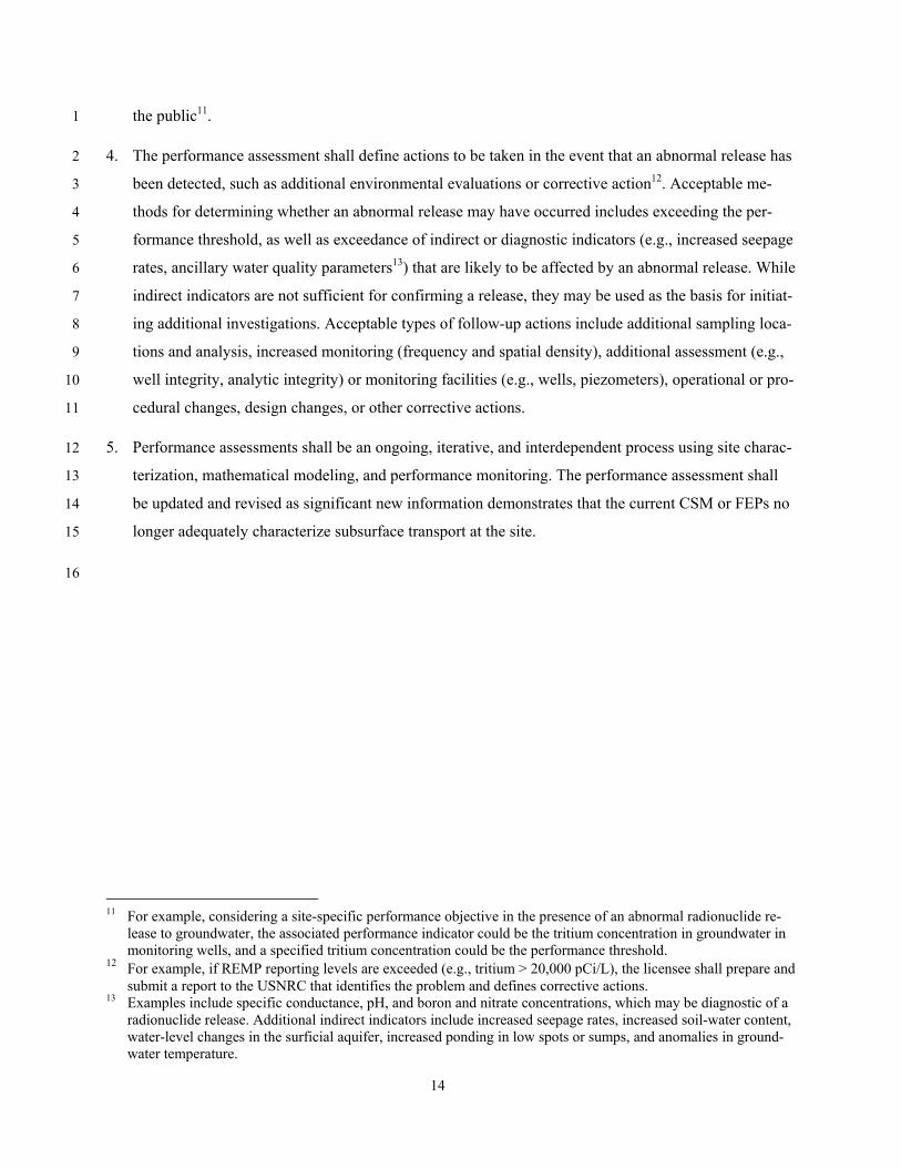
the public11. 1
4. The performance assessment shall define actions to be taken in the event that an abnormal release has 2
been detected, such as additional environmental evaluations or corrective action12. Acceptable me-3
thods for determining whether an abnormal release may have occurred includes exceeding the per-4
formance threshold, as well as exceedance of indirect or diagnostic indicators (e.g., increased seepage 5
rates, ancillary water quality parameters13) that are likely to be affected by an abnormal release. While 6
indirect indicators are not sufficient for confirming a release, they may be used as the basis for initiat-7
ing additional investigations. Acceptable types of follow-up actions include additional sampling loca-8
tions and analysis, increased monitoring (frequency and spatial density), additional assessment (e.g., 9
well integrity, analytic integrity) or monitoring facilities (e.g., wells, piezometers), operational or pro-10
cedural changes, design changes, or other corrective actions. 11
5. Performance assessments shall be an ongoing, iterative, and interdependent process using site charac-12
terization, mathematical modeling, and performance monitoring. The performance assessment shall 13
be updated and revised as significant new information demonstrates that the current CSM or FEPs no 14
longer adequately characterize subsurface transport at the site. 15
16
11 For example, considering a site-specific performance objective in the presence of an abnormal radionuclide re-
lease to groundwater, the associated performance indicator could be the tritium concentration in groundwater in monitoring wells, and a specified tritium concentration could be the performance threshold.
12 For example, if REMP reporting levels are exceeded (e.g., tritium > 20,000 pCi/L), the licensee shall prepare and submit a report to the USNRC that identifies the problem and defines corrective actions.
13 Examples include specific conductance, pH, and boron and nitrate concentrations, which may be diagnostic of a radionuclide release. Additional indirect indicators include increased seepage rates, increased soil-water content, water-level changes in the surficial aquifer, increased ponding in low spots or sumps, and anomalies in ground-water temperature.
15
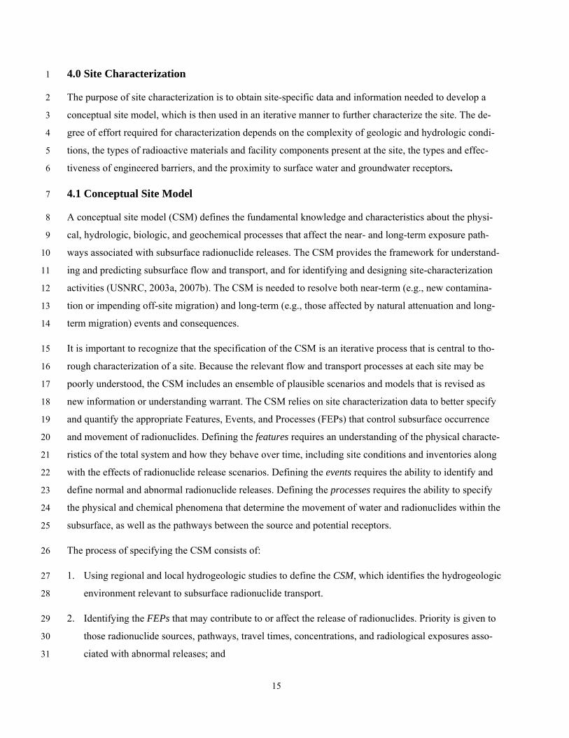
4.0 Site Characterization 1
The purpose of site characterization is to obtain site-specific data and information needed to develop a 2
conceptual site model, which is then used in an iterative manner to further characterize the site. The de-3
gree of effort required for characterization depends on the complexity of geologic and hydrologic condi-4
tions, the types of radioactive materials and facility components present at the site, the types and effec-5
tiveness of engineered barriers, and the proximity to surface water and groundwater receptors. 6
4.1 Conceptual Site Model 7
A conceptual site model (CSM) defines the fundamental knowledge and characteristics about the physi-8
cal, hydrologic, biologic, and geochemical processes that affect the near- and long-term exposure path-9
ways associated with subsurface radionuclide releases. The CSM provides the framework for understand-10
ing and predicting subsurface flow and transport, and for identifying and designing site-characterization 11
activities (USNRC, 2003a, 2007b). The CSM is needed to resolve both near-term (e.g., new contamina-12
tion or impending off-site migration) and long-term (e.g., those affected by natural attenuation and long-13
term migration) events and consequences. 14
It is important to recognize that the specification of the CSM is an iterative process that is central to tho-15
rough characterization of a site. Because the relevant flow and transport processes at each site may be 16
poorly understood, the CSM includes an ensemble of plausible scenarios and models that is revised as 17
new information or understanding warrant. The CSM relies on site characterization data to better specify 18
and quantify the appropriate Features, Events, and Processes (FEPs) that control subsurface occurrence 19
and movement of radionuclides. Defining the features requires an understanding of the physical characte-20
ristics of the total system and how they behave over time, including site conditions and inventories along 21
with the effects of radionuclide release scenarios. Defining the events requires the ability to identify and 22
define normal and abnormal radionuclide releases. Defining the processes requires the ability to specify 23
the physical and chemical phenomena that determine the movement of water and radionuclides within the 24
subsurface, as well as the pathways between the source and potential receptors. 25
The process of specifying the CSM consists of: 26
1. Using regional and local hydrogeologic studies to define the CSM, which identifies the hydrogeologic 27
environment relevant to subsurface radionuclide transport. 28
2. Identifying the FEPs that may contribute to or affect the release of radionuclides. Priority is given to 29
those radionuclide sources, pathways, travel times, concentrations, and radiological exposures asso-30
ciated with abnormal releases; and 31

16
3. Providing quantitative data and information about processes and parameters that allows for the de-1
velopment of a mathematical (parametric) model to help understand and manage the geologic, hydro-2
logic, and geochemical environment at the facility. 3
The CSM shall define the geographic region of concern, which includes the topography, watershed area 4
(i.e., the surface-water drainage basin where the facility is located), and watershed boundaries. Within the 5
specified region, the CSM shall include those hydrographic (e.g., rivers, streams, lakes, ponds, wetlands, 6
estuaries, coastal sea levels), geologic (hydrostratigraphy, faults, hydrogeologic unit interfaces, fracture 7
zones), and hydrogeologic (e.g., phreatic and confined aquifers, confining layers, unsaturated zone, 8
perched systems, springs) features that are likely to affect subsurface radionuclide transport. 9
The CSM shall also include additional features at sites with greater complexity that may be part of, or 10
have direct influence on, transport pathways. These include preferential flowpaths (e.g., buried stream 11
channels, lineaments, fracture connectivity, voids, conduits), adjacent aquifers or watersheds with subsur-12
face flow interactions (e.g., leakage) or pathways, and groundwater-surface-water interactions (e.g., 13
coastal zones, recharge and discharge zones, groundwater-surface-water transition zones (USEPA, 14
2008)). The interaction with these systems is important, in that pathways with limited transport capacity 15
are not as important from a risk and characterization perspective as those that may be affected by an ab-16
normal event. 17
The CSM shall specify the likely radionuclides of concern at the facility, along with the likely pathways 18
for radionuclide movement. This requires a conceptualization of the source term, including type (e.g., liq-19
uid waste management system tank, residual radioactivity in soil), location, volume, mass, concentrations, 20
release mechanisms, etc. In addition, the receptor locations, regulatory boundaries, and target aquifers 21
shall be identified. While the water-table aquifer is likely to be the primary pathway, complex hydrogeo-22
logic conditions may warrant the identification of pathways through other hydrogeologic units (e.g., va-23
dose zone, underlying confined and semi-confined aquifers). The CSM shall also specify the biological 24
and geochemical processes that are likely to affect radionuclide occurrence and transport characteristics. 25
Alternative CSMs shall be proposed as suitable hypotheses (i.e., hypotheses that can be tested using cha-26
racterization or monitoring data) during early stages of site investigations at complex sites (e.g., where 27
fractures or heterogeneities may substantially affect transport behavior). Because reducing uncertainties 28
associated with alternative CSMs is an important component of site characterization, alternative interpre-29
tations regarding the major lateral, upper, and lower hydrologic boundaries of the unconfined aquifer and 30
other physical boundaries (e.g., surface-water bodies, surface outcrops, recharge boundaries) shall be pro-31
vided whenever these alternative interpretations are likely to affect subsurface radionuclide transport. 32
17
Periodic evaluation and updating of the CSM shall be performed every five years (or more frequently to 1
coincide with facility alterations) to assure that observed monitoring data are consistent with the CSM. 2
When updating the CSM, the most current values of hydrogeologic parameters, as well as additional hy-3
drogeologic characterization, mathematical modeling, and monitoring data, shall be included. The effects 4
of seasonal fluctuations, significant recharge events, and droughts shall be used to the extent practicable 5
to improve the CSM. 6
Visualization tools are useful for integration of data and information into figures, graphs, stylized visual 7
diagrams (i.e., cartoons) in both plan and profile views, and shall be used to clearly depict the CSM and 8
alternative CSMs. Relevant site information shall include, but is not limited to, hydrostratigraphy, facility 9
location, boring and well locations, heads in each aquifer, arrows depicting flow direction, and interaction 10
at groundwater-surface water transition zones. 11
4.2 Facilities Characterization 12
Facilities shall be characterized in terms of their specific components, procedures, and processes for 13
which an abnormal radionuclide release may occur, with the goal being to identify the potential release 14
modes along with the likelihood of these releases. Guidance for the evaluation of failure modes can be ob-15
tained from USNRC (1990a).14 16
Facilities. Specific facility information includes the locations and characteristics (e.g., dimensions, con-17
struction materials, hydraulic properties, radionuclide inventories) of the relevant: 18
Surface facilities (e.g., spent-fuel pools, holding ponds, condensate tanks, pipelines); 19
Liquid waste management systems (e.g., for newer facilities, a failure of a liquid waste manage-20 ment system tank shall be postulated and evaluated against the effluent concentration limits given 21 in 10 CRF Part 20. These tanks should be explicitly identified in the list of facilities); 22
Subsurface facilities (e.g., spent-fuel pools, drains, pipes, conduits, artificial fill, backfill, pads, 23 foundations, and the associated vadose zone); 24
Engineered barriers (e.g., liners, caps, cutoff walls, leak detection systems, and interceptor wells); 25
Well construction data (e.g., grouted and screened intervals, screen and casing type, depth, di-26 ameter, perforation, surface seals, aquifers penetrated, location, elevation, use, owner, discharge 27 rates, static hydraulic heads, and drawdown); and 28
Abandoned wells and piezometers, along with the method of abandonment. 29
14 Licensing of new power reactor sites 10 CFR 100.20(c)(3) requires that: “Factors important to hydrological
radionuclide transport (such as soil, sediment, and rock characteristics, adsorption and retention coefficients, groundwater velocity, and distances to the nearest surface body of water) must be obtained from on-site mea-surement.”
18
Modifications. Because the hydrogeologic regime, as well as biogeochemical processes, may be altered 1
by construction and ongoing facility modifications, important surface and subsurface modifications shall 2
be catalogued and updated to reflect actual site conditions. Changes in subsurface flow conditions result-3
ing from new and previous facility construction and operation shall be documented. These changes can be 4
due to groundwater control or foundation improvement activities, such as installation of slurry trenches 5
and rock grouting, or the construction of buildings with deep foundations that act as barriers to groundwa-6
ter flow, and may include changes in hydraulic heads within pertinent aquifers, changes in hydraulic con-7
ductivity, placement of engineered fill, altered surface topography, and changes in the direction or quanti-8
ty of groundwater flow. Anticipated changes in water quality (due to, for example, intrusion of saline wa-9
ter, stormwater or irrigation water infiltration, domestic and municipal wastewater disposal, and induced 10
movement within or between aquifers) shall be assessed and recorded. These construction and facility 11
changes shall be identified and incorporated within the CSM during periodic updates, or whenever per-12
formance thresholds are exceeded. 13
Abnormal releases. Facility operational practices and procedures that are likely to affect the potential re-14
lease and subsequent subsurface movement of radionuclides to the environment shall be identified. Data 15
relevant to past abnormal radionuclide releases include corrective actions implemented, radionuclide in-16
ventories, release locations and magnitudes, travel paths, and travel times to both potential receptors and 17
regulatory boundaries. 18
4.3 Hydrogeologic Characterization 19
Hydrogeologic properties from previous regional studies shall be used to plan the detailed site studies, if 20
available. Because regional properties are not an acceptable substitute for locally derived information, site 21
hydrogeologic properties shall be acquired to either confirm regional estimates, or to provide unique es-22
timates of local conditions. Hydrogeologic information from previous characterization activities that may 23
have been performed for other purposes at the site shall also be used, if available. Technical documents 24
that provide information about or can assist with the development and implementation of hydrogeologic 25
characterization programs include Bennett (1976), Driscoll (1986), USNRC (1988, 2007b), USEPA 26
(1994), Stephens (1996), Faybishenko et al. (2000), Evans et al. (2001), Boulding and Ginn (2003), and 27
Nielson et al. (2006). 28
Baseline conditions. Ambient subsurface flow conditions shall be defined to establish a baseline against 29
which future conditions are compared. Sufficient data shall be collected to characterize the hydraulic 30
head, hydraulic gradients (magnitude and direction), and the natural variation and bounds of these esti-31
mates in the unconfined aquifer, and those confined aquifers identified in the CSM that contribute to risk-32
19
significant pathways. Also, if appropriate to the CSM, sufficient data shall be collected to provide a gen-1
eral description of hydraulic conditions in the vadose zone under extreme conditions (e.g., potential flood-2
ing or full saturation). Data collected to establish baseline conditions are also normally used to support 3
groundwater model calibration and validation. The baseline data collection program shall therefore con-4
sider modeling needs and ensure that the data needed to support modeling are obtained. 5
Baseline conditions shall be monitored with sufficient frequency and duration to define the probable 6
range of dynamic hydrologic behaviors, and to provide the capability for identifying unusual hydrologic 7
responses. Subsurface conditions (in particular, groundwater levels) shall be monitored on a monthly ba-8
sis for at least a year to establish the seasonal variability. More frequent monitoring may be needed in 9
complex fractured rock or karstic systems. Precipitation data shall be used to determine whether the data-10
collection period is representative of the long-term precipitation and recharge conditions. Available his-11
toric local and regional groundwater level measurements should be examined, together with onsite mea-12
surements, for determining the annual variation in groundwater levels. 13
Hydraulic heads shall be measured in those surface waters (e.g., rivers, lakes, wetlands, springs, estuaries, 14
bays, oceans, groundwater-surface water transition zones) identified as relevant to radionuclide transport 15
in the CSM. The relationships between observed surface water and subsurface hydraulic heads shall be 16
used to estimate the average and range of hydraulic head response, as well as their effects on the magni-17
tude and direction of subsurface transport at the facility. In addition to hydraulic head measurements to 18
determine groundwater flow conditions, concurrent estimates of groundwater flow (using, for example, 19
Darcy’s Law) shall also be made to assist in characterizing the water budget and to calibrate groundwater 20
flow models. Flow estimates may also be needed in order to determine dilution factors when contami-21
nated groundwater discharges to perennial stream prior to leaving the restricted area. For sites where the 22
CSM indicates that changes in surface loading (e.g., precipitation, barometric pressure, streamflow, tidal 23
fluctuations, cooling water intake and discharge canals) affect aquifer hydraulic heads, the observation 24
well water-level responses to these processes shall be quantified. Similarly, for facilities in coastal areas, 25
the hydrologic behavior of offshore discharges and tidal influences shall be included if identified in the 26
CSM. For example, the baseline variation in surface and subsurface salinity shall be monitored if they are 27
included in the CSM. 28
Regional and local water-quality data shall be used to resolve ambiguities in the CSM, such as to identify 29
modes of recharge to the aquifers, or flow within complex hydrogeologic environments, and to assess the 30
interaction of groundwater between geologic formations. Tracer tests are an acceptable method for site 31
characterization at complex sites where existing water-quality data fail to resolve ambiguities in the CSM. 32

20
Baseline concentrations of performance indicators (e.g., tritium) shall be collected in pathways identified 1
in the CSM (e.g., precipitation, surface water, coastal waters, groundwater) to determine their spatial and 2
temporal variability, as well as to aid in the specification of performance thresholds. 3
Water budget. The CSM shall include a water budget analysis for the site showing the precipitation, 4
evapotranspiration, runoff, recharge, and groundwater discharge. Groundwater flow models (e.g., numeri-5
cal or algebraic) are useful tools for quantifying the water budget and reconciling field observations. Pub-6
lished information may be used to estimate infiltration as a percentage of precipitation to evaluate evapo-7
transpiration-runoff-recharge relationships. The CSM shall include recharge-discharge relationships be-8
tween surface water and groundwater (and between aquifers, if appropriate), including induced recharge 9
from past and current site operations, and natural recharge from direct infiltration of precipitation, surface 10
water, and site runoff. An important consideration is the variation of short-term (daily to monthly) and 11
long-term (seasonal to decadal) interactions in the water budget, or at time scales defined by the CSM 12
(e.g., shorter intervals may be needed to evaluate tidal and/or streambank exchanges). Other important 13
considerations include the long-term variation in regional recharge and discharge rates, as well as local 14
changes in groundwater flow direction, especially those that may affect radionuclide transport over the 15
facility lifetime. These variations may be assumed constant over appropriately discrete periods (e.g., five-16
year increments) and evaluated for a suitable range of aquifer recharge and discharge conditions. In addi-17
tion to using precipitation data to assess whether the data-collection period is representative of long-term 18
conditions, drought indices (e.g., Palmer Drought Severity Index) may also be helpful in determining the 19
representativeness of the data as they typically consider the cumulative effects of above- or below-20
average precipitation. 21
Transport pathways. Sufficient data shall be collected to evaluate transport in pathways identified by the 22
CSM. This requires, at a minimum, the identification of regional groundwater and surface water uses and 23
potential receptors, and the calculation of travel times and flow paths. Calculation using simple mathe-24
matical models is appropriate at sites with limited hydrogeologic complexity and exposure risks. For 25
complex conditions or with greater risks, additional site-specific data on transport, such as the effective 26
porosity and dispersivity, may be needed, along with more complex numerical flow and transport models. 27
Core-sample analyses and field tracer tests are acceptable methods for determining site-specific transport 28
properties. 29
Physical properties. Site-specific physical properties of the hydrogeologic units shall be collected to un-30
derstand and predict radionuclide transport at the site. Of primary interest are the physical properties that 31
affect flow and transport characteristics, including the bulk density, total and effective porosity, grain-size 32
distribution, and mineralogical composition. Physical properties that might affect radionuclide transport, 33
21
such as preferential flowpaths (e.g., faults, lineaments, fractures, voids, conduits), shall be characterized, 1
including their frequency, dimensions, orientation, and interconnectivity. Spatially explicit data shall be 2
collected using continuous soil or rock samples as well as surface and subsurface (borehole) geophysical 3
methods, as appropriate to the complexity of the site. 4
Hydraulic properties. The hydraulic properties of hydrogeologic units that have been specified in the 5
CSM as providing pathways to potential receptors or to compliance locations shall be characterized. To 6
be conservative, all aquifers that provide pathways of concern shall be characterized, plus the next under-7
lying hydrostratigraphic unit. This characterization includes test borings in these units, at least one of 8
which at complex sites would be used to collect a continuous set of samples spanning the length of the 9
borehole. Borehole geophysical logging shall be performed in selected test borings. Borings shall be con-10
ducted in a manner that they do not create subsurface radionuclide pathways. In-hole horizontal and ver-11
tical flow measurements shall be conducted in selected test borings, if appropriate, to identify zones with 12
higher flow rates for both ambient-flow and stressed (e.g., pumping) conditions. Acceptable methods for 13
conducting surface and subsurface geophysical studies to characterize preferential flow paths include hy-14
draulic tomography, tracer tests, seismic arrays, and electromagnetic techniques. 15
Quantitative estimates of hydraulic parameters identified as relevant by the CSM (e.g., hydraulic conduc-16
tivity, transmissivity, specific storage, specific yield, specific capacity, storativity, leakance) shall be ob-17
tained using aquifer tests (e.g., single and multiple borehole pumping tests, slug tests, specific capacity 18
tests, falling/rising head tests, borehole flowmeter or dilution tests). For anisotropic media, the directional 19
components of hydraulic properties are also important and shall be obtained with appropriate tests. Again, 20
special interest is placed on the hydraulic properties of features identified in the CSM that may affect ra-21
dionuclide transport, such as preferential flowpaths (e.g., faults, lineaments, fractures, voids, conduits). 22
Transport through the vadose zone may be assumed to be instantaneous for purposes of obtaining con-23
servative estimates of travel times (thus eliminating the need for defining vadose zone hydraulic proper-24
ties). Yet, the interpretation of monitoring well responses might require detailed vadose zone characteri-25
zation. If vadose zone characteristics are relevant, the moisture characteristic curves and unsaturated hy-26
draulic conductivity functions shall be determined15. 27
Estimates of ambient flow magnitudes and directions for a range of hydrologic conditions shall be deter-28
mined. These estimates shall be confirmed using tracer or borehole methods at complex sites. The use of 29
15 A practical way to accomplish this is to use, for example, pedotransfer functions based on particle-size distribu-
tions, such as described by Schaap et al. (2001), although laboratory-derived functions may be needed, depending upon the extent to which the vadose zone affects facility performance.

22
in situ borehole flowmeters is acceptable for evaluating the vertical flow direction within and between 1
hydrogeologic units. 2
Chemical properties. In cases where an abnormal release has occurred or is suspected, sufficient data 3
shall be collected to define the fluid chemistry and potential reactions of formation fluids and solids from 4
the release. Appropriate transport characterization parameters (e.g., total ion-exchange capacity, distribu-5
tion coefficients, pH, redox potential) shall be determined for performance indicators that are affected by 6
geochemical processes. Laboratory measurements of the distribution coefficient for individual nuclides 7
shall be obtained if conservative values16 produce estimates of contaminant transport that do not satisfy 8
performance objectives. These measurements shall be made using samples of the materials found along 9
critical groundwater pathways and groundwater from the site. Column tests with undisturbed core sam-10
ples are preferred. In the event that undisturbed core samples are not available, they may be replaced by 11
batch tests with grab samples. However, it should be noted that the latter tends to result in distribution 12
coefficients that are larger than in-situ values. The effects of chelating agents and other chemicals that 13
might be present in a liquid effluent release and are known to enhance the mobility of radionuclides in 14
groundwater shall be determined. The influence of biological processes (e.g., plant water uptake) on hy-15
drogeologic and geochemical processes shall be included, if appropriate. 16
17
16 Either zero for new power plants (10 CFR 100.20(c)(3)) or determined from published literature otherwise.

23
5.0 Mathematical Modeling 1
The modeling goal is to assist in the risk-informed understanding and prediction of groundwater flow and 2
transport. Mathematical modeling shall be used to support performance assessment by demonstrating that 3
design and regulatory-compliance goals are met during the design and permitting stages, as well as during 4
the operation and decommissioning stages. During the design and permitting stages, mathematical models 5
assist in demonstrating facility safety (with characterization and monitoring data being used to establish 6
model accuracy), for planning, designing, and evaluating monitoring strategies, for performing radiologi-7
cal exposure assessments, for evaluating the effects of facilities (including normal radionuclide releases, 8
if necessary) on the hydrologic system, and as an integration tool for documenting and analyzing hydro-9
geologic processes and assumptions. During the operation stage, models assist in interpreting monitoring 10
data, determining the source, direction, and rate of movement of abnormal releases, and estimating the 11
zone of contamination, if present. Because model predictions are compared with monitoring data at regu-12
lar intervals, models assist in updating the CSM as new information and insight of system behavior is 13
gained. A robust modeling program also provides valuable assistance during the decommissioning stage 14
by anticipating the likely occurrence and movement of radionuclides in the subsurface. 15
While recognizing that monitoring data are key to demonstrating the continuing safety of the facility dur-16
ing the operational stage, it is important to note that mathematical models provide additional utility by in-17
tegrating hydrologic parameters and processes, testing CSM interpretations when monitoring data are 18
ambiguous, counter-intuitive, or do not provide sufficient confidence in system performance. Models are 19
also important for reconciling monitoring and characterization data with the CSM, to estimate the poten-20
tial movement of contaminants on the site, and to develop mitigation plans for the purpose of preventing 21
offsite migration of contaminations. As such, modeling is a tool that supports the groundwater-monitoring 22
program and performance testing of CSM hypotheses. Models are especially helpful for determining flow 23
directions and magnitudes, as well as for determining the rate of groundwater and radionuclide movement 24
in response to natural and anthropogenic stresses. 25
5.1 Model Scope 26
The mathematical model shall incorporate the physical and chemical processes and parameters relevant to 27
describing the flow and transport of radionuclides at the site. Model scope shall incorporate the appropri-28
ate FEPs, and provide documentation to support the proposed level of model complexity, including, as 29
required, the spatial extent, heterogeneities, scale effects, transient perturbations, etc. The model calibra-30
tion accuracy shall be determined using a documented process of model testing and field confirmation. 31
The analytic or numeric methods for model implementation shall be defined for both fluid flow and ra-32

24
dionuclide transport. The model selection process shall demonstrate that model capabilities are consistent 1
with the appropriate processes, parameters, site conditions, and data availability. 2
The level of effort associated with mathematical modeling shall be consistent with the degree of complex-3
ity and uncertainty in the underlying CSM, hydrogeologic conditions, the inventories and types of radio-4
nuclides that may be released to the subsurface, the proximity to potential receptors, and exposure path-5
way mechanisms. The appropriate level of model complexity balances model accuracy against modeling 6
effort, with the ultimate goal being the risk-informed understanding and prediction of subsurface transport 7
of radionuclides. An acceptable model at sites where the hydrogeologic setting is simple and the potential 8
for risk to receptors is remote is an algebraic equation using Darcy’s Law that is solved manually. 9
Coupled, partial-differential equations that are solved numerically are acceptable for: i) heterogeneous 10
and active groundwater systems, ii) liquid, vapor, and gas fluxes in the unsaturated zone, iii) dual porosity 11
flow and transport through heterogeneous media (Freehley et al., 2000), iv) regional flow and transport 12
through confined aquifers and confining layers below the unconfined aquifer (Aral, 1990); v) sites with 13
complex hydrogeologic conditions in close proximity to potential receptors; and vi) sites where an ab-14
normal release has occurred. 15
For a simple flow regime, it is acceptable in an initial transport analysis to account for advection and ra-16
dioactive decay only. If the estimated concentrations meet the performance objectives, no further analysis 17
is needed.17 If not, then analysis shall consider additional processes as defined by the CSM, including e.g., 18
radionuclide fluxes in aqueous, sorbed, vapor, and gaseous phases, and associated hydrologic processes 19
and mass-transport phenomena including e.g., advection, diffusion, volatilization, hydrodynamic disper-20
sion (longitudinal and transverse), adsorption, and radioactive chain decay. 21
Additional useful modeling guidance can be found in Yeh (1981), Aral (1990), NRC (1990), Anderson 22
and Woessner (1992), Mercer and Faust (1992), Wang and Anderson (1995), Chien et al. (2003), USNRC 23
(2003a), and Fetter (2008). Additional guidance for modeling contaminant transport is available in Codell 24
and Duguid (1983), Wexler (1992), and Zheng and Bennett (2002). 25
Spatial scale of analysis. The model shall include potential onsite and near-boundary receptor locations, 26
as defined by the CSM. The model shall resolve features that affect flow and radionuclide transport for 27
normal releases, as well as for abnormal releases, as defined by the CSM. To the extent feasible, the mod-28
el shall incorporate natural hydrological boundaries such as rivers or basin margins, rather than terminat-29
17 Tritium is a useful radionuclide for modeling because it can be assumed to move at the same rate as
water, unaffected by chemical processes such as sorption.

25
ing the model area at arbitrary locations unrelated to hydrologic conditions, such as property boundaries. 1
Temporal scale of analysis. The model shall simulate flow over a representative time period because 2
flow conditions may change due to changing site operations, stresses (e.g., recharge, discharge), boundary 3
conditions (e.g., lateral inflows and outflows, heads), and land use. Historical data shall be used for initial 4
model calibration while model predictions shall be compared against monitoring data for model evalua-5
tion. 6
Model geometry. The model geometry shall be consistent with the CSM. Use of a simplified geometry18 7
is acceptable as long as it is consistent with the CSM. It is acceptable for the flow and transport model 8
dimensionalities to differ.19 9
Flow parameters. The mathematical model shall incorporate those flow parameters relevant to the CSM. 10
The model shall represent the spatial variability of these parameters as determined using characterization 11
and monitoring data. In addition, site-specific components (sources, artificial fill, backfill, geotechnical 12
properties) shall be included, along with the characteristics of natural and induced preferential pathways 13
of significance, as defined by the CSM. 14
Hydrologic boundaries. Appropriate time-dependent and spatially varying Dirichlet (head), Neumann 15
(fluid flux), or Cauchy (mixed) boundary conditions, and appropriate time- and space-dependent sources 16
and sinks of fluids shall be used, as defined by the CSM. Combinatory (composite) modeling techniques 17
are acceptable for establishing interfaces between vadose-zone and surface-water model(s). 18
Radionuclide retardation. If identified in the CSM, the model shall simulate geochemical retardation on 19
a radionuclide-specific basis. Using a linear-equilibrium adsorption model meets the intent of this model 20
component; however, the user should be prepared to justify use of linear or non-linear isotherms for spe-21
cific radionuclides. The capability to allow adsorption to vary not only by radionuclide, but also spatially 22
(i.e., to be a function also of the hydrogeologic unit in which transport occurs), shall be included if identi-23
fied in the CSM. 24
Dispersion and molecular diffusion. If identified in the CSM, the model shall simulate dispersion and 25
molecular diffusion on a radionuclide-specific basis. Using a constant dispersivity meets the intent of this 26
model component; however, the user should be prepared to justify approaches for spatially uniform or va-27
riable dispersivity. 28
18 For example, one-dimensional flow tube, horizontal, two-dimensional flow through confined aquifers, and vertic-
al one-dimensional fluid flow through confining layers and the unsaturated zone. 19 For example, a multi-dimensional flow model may be needed to define the flow path from a release point, but a
one-dimensional transport analysis along this path may be adequate.

26
Radioactive decay. If identified in the CSM, the model shall simulate the effect of first-order radioactive 1
decay. The capability to simulate first-order radioactive decay can be important for radionuclides whose 2
half-life is sufficiently short, and travel times are sufficiently long, to affect observed concentrations. This 3
capability may also be useful in estimating the effect of chemical degradation if the degradation process 4
can be approximated using this type of decay function. While chain decay is not usually significant for 5
most of the mobile radioactive constituents, there may be instances where the capability to calculate the 6
effect of chain decay in transport simulations is a desirable feature, particularly in cases where the decay 7
products are mobile, have greater toxicity than the parent, or are detected as part of the monitoring pro-8
gram. 9
Flowpath modeling. If identified in the CSM, the model shall provide streamline (for steady-state condi-10
tions) and pathline (for transient conditions) analyses in two and three dimensions. Predicting radionuc-11
lide migration rates and directions requires additional information about the effective porosity and sorp-12
tion capabilities of the aquifer. One method for evaluating predictive model accuracy is to compare mod-13
el-calculated radionuclide flow behavior with field measurements and observations of natural or artificial 14
tracers. 15
Reactive transport or transport with chemical transformation. If defined in the CSM, the model shall 16
perform transport calculations of reactive radionuclides (e.g., Sr-85). Reactive transport models have the 17
capability to simulate complex radionuclide-transport behavior in the vicinity of certain facility and ra-18
dionuclide release locations (Brusseau, 1994; Goldberg et al., 2007). In analyzing the behavior of reactive 19
radionuclides, consideration should be given to the presence of organic or inorganic complexants in the 20
released liquids during the accident. Also, consideration should be given to the effect of chelates on ad-21
sorption. The use of reactive transport models, however, is not presently viewed as practical because of 22
substantial geochemical data and computational requirements, but should be used in appropriate circums-23
tances when such models become practicable or if particularly simple, but important, chemical reactions 24
are involved. 25
5.2 Calibration, Prediction, and Updating 26
Model calibration. The primary goal of model calibration is to establish that the CSM adequately 27
represents site conditions, as evidenced by the ability to minimize discrepancies between observed and 28
predicted behavior. Characterization data from literature sources may not provide sufficient spatial detail 29
to resolve predictions at the local scale, and may require additional, site-specific characterization data. 30
Monitoring data from the site shall be used to evaluate model predictions, and these data shall be obtained 31
with sufficient spatial and temporal resolution to allow appropriate comparisons. Hydrologic and water-32

27
quality observations shall be compared with model predictions using natural (hydrometeorological) and 1
anthropogenic (pumping, recharge, tracer) events. 2
Where appropriate observed data exist, model calibration shall compare observed with simulated condi-3
tions for hydraulic heads, hydraulic gradients, groundwater flow directions, water mass balances, and ra-4
dionuclide concentrations, migration rates, and directions. These comparisons shall be presented as maps, 5
tables, or graphs. The objective of calibration is to minimize the statistical difference between observed 6
and simulated conditions. Typically, the mean absolute residual error (mean absolute difference between 7
observed and simulated groundwater flow conditions) should be less than ten percent of the variability in 8
the field data across the model domain. In the event that radionuclide concentration(s) span over several 9
orders of magnitude, uncertainties associated with groundwater transport conditions (typically measured 10
by the mean absolute residual of the logarithmic concentration error) should be less than an order of mag-11
nitude (i.e., less than one on a logarithmic scale), and shall include a conservative bias. . A description of 12
model-calibration procedures shall be provided, along with calibration data sets and assumptions. Differ-13
ences between model predictions and field observations shall be discussed. 14
Periodic model calibration shall be performed in conjunction with updating of the CSM, as noted in Sec-15
tion 4.1. During calibration, it is important to focus on circumstances when predictions are inconsistent 16
with field observations, because inconsistencies could indicate a fundamental error in the CSM, mathe-17
matical representation, or field measurement; or that an abnormal event has taken place. Regardless of the 18
cause, efforts should be taken to evaluate what led to the inconsistency so that either the errors are re-19
solved and avoided in the future, or the abnormal event is further evaluated. Model results that indicate 20
significant deviations from the CSM should be used to revise or update the CSM, or to further evaluate 21
the monitoring strategy. 22
Additional information about model calibration can be found in model-calibration literature that includes 23
Hill and Tiedeman (2007). 24
Model predictions. Models shall be used to make predictive estimates of radionuclide concentrations at 25
appropriate compliance points. The model shall represent future conditions consistent with source terms, 26
boundary conditions, and material properties (using either best estimate or bounding values) as defined in 27
the CSM (and alternative CSMs, where present) to assure that the predictive model is bounding and pro-28
tective of the public. 29
Model updating. The conceptual and mathematical models need to provide a flexible and evolving plat-30
form for analyzing flow and radionuclide transport at the site. As more data are collected, it is likely that 31
predictive capabilities of the associated model will be enhanced. Thus, an iterative, interdependent, ongo-32

28
ing effort toward reconciling monitoring data with the CSM is an important part of model updating. Mod-1
el forecasts are compared with monitoring data, and vice versa. In essence, one can view the iterative and 2
interdependent process as computer-aided thinking and evaluation (modeling) that is continuously refined 3
by measurements (monitoring). Additional monitoring locations, characterization activities, or model 4
complexity may be required to assist with this analysis, especially if source terms have changed. The 5
adopted model framework is one in which new concepts shall be tested by incorporating additional data. 6
5.3 Uncertainty Assessment 7
Model uncertainties can be traced back to three basic sources: natural heterogeneity, measurement errors, 8
and structural differences between the CSM and the real world system (USNRC, 1990). Model uncertain-9
ties shall be explicitly identified and estimated with respect to various assumptions in the CSM (e.g., un-10
anticipated features, events, processes), hydrogeologic data and parameters (e.g., measurement and statis-11
tical variation in hydrogeologic properties, baseline, and boundary conditions, over space and time), and 12
mathematical codes (e.g., mathematical approximation of processes, numerical errors). Acceptable and 13
widely used methods for accounting for model uncertainties include using explicit or implicit margins of 14
safety, bounding or best-estimate (expected value) approaches, stochastic (Monte Carlo) methods, and 15
probabilistic risk assessments.20 16
In circumstances where model uncertainties indicate a significant risk of failure in achieving performance 17
objectives, acceptable and widely used methods for reducing model uncertainties include a) improved 18
characterization, monitoring, and sampling methods (e.g., alternative monitoring network design, more 19
frequent or accurate measurements), b) alternative CSM definition (e.g., consideration of alternative fea-20
tures, events, and processes), and c) improved model calibration (e.g., statistically based parameter opti-21
mization techniques, sensitivity analyses, and Monte Carlo simulations). Also acceptable and widely used 22
is a sequential, multi-stage (i.e., each stage planned and executed based on information from previous 23
stages) site characterization, monitoring, and modeling strategy that take full advantage of these three me-24
thods. Because transport models are sensitive to local heterogeneity of aquifer properties, the scope of da-25
ta collection and modeling is likely to be related to the complexity of the model and the geologic. The se-26
quential, multi-stage strategy where site characterization, data collection, and model calibration are per-27
formed iteratively provides an opportunity to efficiently reduce uncertainties to acceptable levels. 28
29
20 Use of probabilistic methods requires a result commensurate with the performance objective. For example, when
comparing the results of a probabilistic analysis to a deterministic compliance criterion, the mean result should be used unless otherwise specified in regulations or guidance (USNRC 2009a; USNRC 2000b).

29
Additional information about uncertainty assessment can be found in Saltelli et al. (2000), Helton et al 1
(2006), and USNRC (2000b, 2003a, 2009a). 2
3
30
6.0 Performance-Confirmation Monitoring 1
Monitoring shall be used to support performance assessment. The primary purpose of monitoring is to 2
provide an evaluation process that assures that an abnormal release will be detected, and that facility 3
components comply with performance objectives and meet necessary state and federal regulatory stan-4
dards. Another purpose is to confirm the accuracy of the CSM. This implies that the monitoring program 5
provides ongoing confirmation of the understanding of radionuclide concentrations in groundwater. 6
Monitoring is also important for guiding actions if an abnormal release is detected. The monitoring pro-7
gram provides information about the source, magnitude, migration rate, and potential exposures asso-8
ciated with the release. 9
The monitoring strategy considers site risk factors (e.g., geologic complexity, distance to potential recep-10
tors, depth to groundwater), so that extensive monitoring may not be appropriate at all sites. Additional 11
information regarding monitoring data can be found in Freeze and Cherry (1979), USNRC (1990b, 12
2007b, 2008), USEPA (1994), Stephens (1996), Colin and Quevauviller (1998), Fetter (2000), Ward et al. 13
(2004), Nielsen (2006), NEI (2007), Rosenberry and LaBaugh (2008), and EPRI (2008). 14
6.1 Types of Monitoring Data 15
Hydrology. The hydraulic head shall be monitored because its spatial and temporal variation controls 16
(along with the hydraulic conductivity and specific storage or water content) the rate and direction of wa-17
ter movement, and the change in fluid storage. Water-level measurements are adequate at low-risk sites, 18
while more detailed (e.g., water flux,flow, multi-level contaminant) monitoring shall be conducted at 19
complex sites. 20
Water flow (e.g., from leak detection systems, drains, vertical flow within boreholes, and into lysimeters 21
placed within the unsaturated zone) shall be monitored at complex sites because it directly indicates sub-22
surface flow. The water content, or saturation, within the unsaturated zone shall be monitored when the 23
depth to the water table is significant because it responds to changes in flow at the surface or from subsur-24
face releases. The soil water potential shall be monitored where unsaturated flow is important because it 25
is needed to calculate the hydraulic gradient and the water flux. 26
Additional ancillary hydrologic data that influence subsurface conditions (e.g., precipitation, streamflow, 27
barometric pressure, tidal stages) may also be monitored, especially if these data assist in discriminating 28
between natural variability and a hydraulic response resulting from an abnormal release. Yet, the hydrau-29
lic change caused by an abnormal release may fall below detection levels, even when these external influ-30
ences are removed from the data. 31
31
Water quality. Subsurface water quality shall be monitored, as defined by the performance indicators. 1
Tritium concentration is a likely performance indicator because of its ubiquity at nuclear facilities and its 2
conservative transport nature (i.e., it is not sorbed and does not decay over short time periods). Monitor-3
ing for other radionuclides depends upon the anticipated inventory or release scenarios at the site, along 4
with other factors including the solubility, mobility, and volatility of the radionuclide. Screening mea-5
surements (e.g., gross alpha, gross beta, total gamma) may also be used as an indicator of radionuclide 6
presence. Additional parameters (e.g., temperature, specific conductance, pH, dissolved oxygen, redox 7
potential, boron) may be used as additional indicators of abnormal releases, depending upon site condi-8
tions and possible release scenarios. 9
6.2 Monitoring Methods 10
Sites with low risk for groundwater contamination, with greater distances to receptors, or with simple 11
flow geometries, need not be monitored as comprehensively as those where increased risks or complexi-12
ties are present. 13
Hydrology. Acceptable methods for monitoring the hydraulic head in the saturated zone include manual 14
measurement of depth-to-water in piezometers at low-risk sites. Water-level recorders (e.g., pressure 15
transducers, capacitance probes) placed in nested piezometers (i.e., wells installed at multiple depths) 16
shall be used at sites with complex hydrology. Where appropriate to the CSM, ambient and induced fluid 17
flows within a well shall be monitored using borehole flowmeters to determine vertical flow components. 18
Where appropriate to the CSM, the hydraulic head in the unsaturated zone shall be determined using ten-19
siometer probes or other sensors with an operational range appropriate for the soil conditions, or inferred 20
from the soil-moisture content using time-domain reflectometry in conjunction with moisture characteris-21
tic curves. Where appropriate to the CSM, flux through the unsaturated zone shall be estimated using cap-22
ture-type lysimeters, or using the hydraulic gradient (from soil water potential measurements) and the un-23
saturated hydraulic conductivity function, as described above. Where appropriate to the CSM, water ex-24
change across the groundwater-surface water transition zone shall be determined or inferred using an ap-25
propriate technique. Exchange may be determined using water-level measurements in nested piezometers 26
installed at multiple depths combined with vertical hydraulic conductivity estimates. Alternatively, ex-27
change may be determined from seepage runs (measurement of streamflow gain or loss in selected reach-28
es), or by the use of seepage meters 29
Water quality. Water quality samples shall be collected to demonstrate compliance with performance ob-30
jectives. A wide array of sampling devices (e.g., portable pumps, dedicated pumps, bailers in oxic condi-31
tions) and sampling techniques (purging multiple well volumes, low flow sampling, no purge sampling) 32
32
are available. Where appropriate to the CSM, water quality data may be collected in situ using dedicated 1
probes (e.g., temperature, specific conductance, pH, dissolved oxygen, redox potential, gross alpha, gross 2
beta, gamma), allowing for the early detection of water quality changes. Where appropriate to the CSM, 3
gas-phase sampling shall be used to determine the presence of volatile radionuclides (e.g., tritium, carbon-4
14, iodine-129) and daughter products (e.g., helium-3) in the unsaturated zone. Surface and subsurface 5
resistivity arrays are suitable methods for detecting subsurface changes in soil moisture content or elec-6
trical conductivity. 7
6.3 Monitoring Locations and Frequencies 8
The number and location of monitoring wells needed to evaluate performance objectives depends upon 9
site conditions, as defined in the CSM. The monitoring system shall be capable of measuring performance 10
indicators that demonstrate compliance with applicable state and federal criteria, especially near the com-11
pliance boundary and intermediate points of compliance. 12
Flow and transport models developed for the site provide important guidance for finding optimal monitor-13
ing locations. These monitoring locations shall be close enough to the locations where a release to the 14
subsurface may occur to ensure that the source of the detected contamination is identified. However, 15
monitoring well locations are often constrained by proximity to subsurface structures, systems and com-16
ponents - their presence shall not interfere with normal operations. Likewise, wells should not be placed 17
in areas where the surrounding infrastructure interferes with sampling and maintenance. 18
Monitoring locations include preferential flowpaths identified in the CSM because an important monitor-19
ing goal is to assure that plumes do not escape detection. Also, the farther the wells are from the facility, 20
the more important it will be to consider the likely vertical trajectory of possible radionuclide plumes. 21
Both the unconfined and confined aquifers (potentially at multiple depths in a deep, unconfined aquifer) 22
shall be sampled if downward flow conditions are present. The unsaturated zone shall be monitored if the 23
depth to water is substantial and is identified in the CSM as being a critical pathway. 24
While water levels and water-quality samples have traditionally been collected from permanent, long-25
screen monitoring wells or piezometers, vertical ambient flow in such wells may compromise these mea-26
surements (Elci et al., 2001, 2003). To avoid these problems, samples should be taken over short, vertical 27
intervals whenever possible to provide higher resolution information about hydraulic-head and water-28
quality variation with depth. In place of long-screen wells, various types of multi-level sampling wells are 29
available, along with methods for converting long-screen wells into multi-level samplers. 30
At least one sampling well shall be placed upgradient of the facility to provide local baseline water quali-31
ty data. The possibility that abnormal releases may alter local hydraulic gradients, inducing flow in unan-32
33
ticipated directions shall be considered. Monitoring wells placed near topographic lows may be useful for 1
detecting releases to surface water that accumulate in these areas. Examination or control of surface ele-2
vations aids in the design of the well monitoring infrastructure. 3
Additional monitoring wells shall be placed downgradient of those components identified in the characte-4
rization of operating facilities from which releases may occur. The number and location of the wells shall 5
be sufficient to detect significant water-quality changes due to radionuclide releases from those facilities. 6
Because hydrologic conditions tend to vary over time, a key aspect of monitoring data management is the 7
routine statistical characterization of monitoring data, especially performance indicators. Identification of 8
trends and anomalous hydrologic behavior provide important information about system performance. 9
Short-duration releases may not be detected if transport is rapid and sampling is not sufficiently frequent. 10
The sampling frequency shall be sufficiently often such that sampling is able todetect intermittent or brief 11
releases. Also, the hydrologic effects (e.g., water-level fluctuations) due to precipitation, barometric, and 12
tidal fluctuations shall be monitored at sub-hourly frequencies (e.g., 15 minutes) if these effects have been 13
identified as important in the CSM. Automated data-logging capabilities are available for collecting wa-14
ter-level, water-quality, and gas-phase data at these frequencies and with acceptable precision. In some 15
cases, these instruments may be connected wirelessly to provide real-time monitoring data capability. 16
Engineered barriers may improve the likelihood of detecting an abnormal release. The establishment of a 17
cone of depression under potential release sites (e.g., a capture zone created by a pumping well that inter-18
cepts and removes radionuclides that reach the water table) may provide a method for containing and de-19
tecting releases. Data from appropriately designed and installed extraction wells or vapor-capture systems 20
with ancillary monitoring equipment could provide an early warning for both tritiated water in the satu-21
rated zone and tritium vapor in the unsaturated zone, respectively. These systems could also be used for 22
corrective action by maintaining positive control during a release. If used, the capture zone shall be de-23
signed in conjunction with other engineered-barrier and leak-detection systems. 24
25
34
7.0 Information Management 1
Important components of performance assessment are the documentation of data, the demonstration of the 2
integrity of its analysis, and maintenance of the supporting databases throughout the life cycle of the mon-3
itoring program. These components are important because the ability to access site information is funda-4
mental to supporting the CSM and increases the confidence in meeting performance objectives. Docu-5
mentation shall contain the hydrogeologic data and information that provides the basis for the CSM, as 6
well as the key interpretations of geologic and hydrologic data and information, including descriptions of 7
methods and approaches used to make these interpretations. Documentation is updated as new data on 8
both the local and regional scale become available. 9
This section provides guidelines for managing information about the CSM, site characterization and mon-10
itoring data, the accuracy of—and the procedures used to procure—these data, and the mathematical 11
models used to analyze these data and to evaluate and revise the CSM. 12
7.1 Characterization and Monitoring Data Management 13
Conceptual site model management. The current state of and revisions to the CSM shall be documented 14
to clarify the dynamic understanding of the FEPs at the site. The CSM shall be updated whenever addi-15
tional characterization and monitoring data indicate the need to do so. Documentation consists of main-16
taining an archive of the various CSMs, along with the changes and the justification or reason for these 17
changes. The CSM(s) are best documented as a set of two-dimensional (plan and profile) or three-18
dimensional (isometric) graphics which qualitatively present the interrelationships between the FEPs, 19
along with supporting text (Shah, 2004). 20
Sampling methods and equipment. Field monitoring equipment installation and sampling methods shall 21
adhere to those defined by ASTM International (previously known as the American Society for Testing 22
and Materials) (ASTM, 1996; ASTM, 1999) and National Ground Water Association guidelines (NGWA, 23
1998) whenever practicable. Sampling methods and equipment shall be standardized and documented as 24
early as possible in the monitoring program in order to avoid spurious variation in monitored parameters 25
resulting from inconsistent sampling techniques. 26
Data quality. Data-quality objectives (DQOs) are used to specify sampling and analytical protocols, spe-27
cifically with respect to sampling frequencies, precision, and accuracy. A DQO process shall be estab-28
lished to define the type, quality, and quantity of data needed to satisfy performance objectives. A robust 29
data quality-assurance/quality-control program ensures that collected data meet these DQOs. Examples of 30
acceptable methods for assessing data precision include field duplicates and laboratory replicates. Exam-31
ples of acceptable methods for assessing data accuracy include the use of calibration standards, matrix 32
35
spikes, and blanks. Example methods for assessing data completeness include the comparison of the 1
number of valid measurements with the planned number of analyses. Multivariate statistical analysis of 2
the data is an acceptable method for identifying Type I and Type II errors and for correcting measurement 3
bias. 4
Data limitations. Minimizing data limitations assists in CSM development and mathematical model im-5
plementation. The sources of field and laboratory uncertainty shall be quantified and minimized. Sources 6
of uncertainty include, but are not limited to, well construction (e.g., casing integrity, screen locations, in-7
advertent pathways, grout contamination, insufficient well productivity) and sampling protocols (e.g., 8
low-flow sampling, pumping vs. static monitoring, sample representativeness). 9
Parameter databases. Databases provide a resource for routine electronic storage of, and access to, data 10
and information about the site hydrogeology, which are used for modeling and data interpretations, site 11
operations, support of decision making, and communication with stakeholders. Methods and approaches 12
used to develop the parameter estimates are included as metadata. Databases also provide sufficient in-13
formation to define parameter distributions (e.g., mean, variance) for hydrogeologic data (e.g., geometry 14
of the main hydrogeologic units, hydraulic properties, boundary conditions, initial conditions, locations 15
and volumes of sources and sinks, artificial and natural recharge estimates). Structured correctly, a rela-16
tional database assures data consistency by allowing comparative analyses throughout the life of the data 17
collection effort. 18
Spatially explicit information shall be stored in a standardized geo-referenced coordinate system to facili-19
tate presentation using a geographic visualization platform (Shah, 2004). Time-series data, particularly 20
performance indicators, shall be presented as time-series plots, with statistical characterization including 21
trend analyses. The data and associated plots and statistical characterization shall be updated routinely. 22
Databases shall be preserved using an industry-standard, computer-readable format so that a third party 23
can use the information to reasonably reproduce temporal or spatial analyses. Databases using proprietary 24
formats should be avoided, because of uncertainties in the ability to access them over time. Instead, con-25
sider developing the database in open (free) format with adequate consideration for metadata storage. 26
7.2 Mathematical Model Management 27
Verification. Evidence of verification of the numerical implementation of the mathematical model 28
(whether equation or computer code) shall be maintained. Verification provides evidence that the solution 29
methods used in the model are correct and demonstrates the effect of the assumptions and potential errors 30
arising from model limitations. Verification evidence includes comparison of model results for a variety 31
of known or accepted solutions. Previous applications of the selected model, or other evidence that the 32

36
model is well regarded by the regulatory community, shall be used to establish model credibility. 1
Configuration control. Models shall be maintained under configuration control, i.e., computer code ver-2
sion numbers or equation forms shall be documented. This includes the databases supporting the CSM 3
and its mathematical implementation, whether equations or computer code. Multiple computer codes may 4
be required to address all significant migration pathways as identified in the CSM. If multiple codes are 5
used, then the relationships between these codes shall be provided. 6
Documentation. Model documentation (e.g., user manuals, computer source and executable code, basic 7
model data) shall be preserved as formal documents or in standardized documentation packages that are 8
not affected by the vagaries of computer technology (rapid advances in computer and modeling technolo-9
gy may render stored versions irretrievable). Documentation shall be sufficiently complete and detailed 10
(e.g., objectives, processes, parameter values, boundary and initial conditions, individual simulations us-11
ing variable parameters or conditions, results, and interpretation of the results) so that the model can be 12
accurately re-created for future modeling programs. Documentation also includes model calibration re-13
sults and statistics, details of successive model revisions, and model limitations. 14
Availability. Because of the need for transparency and verification of modeling results, the mathematical 15
model (whether equation or computer code, along with model inputs, user manuals, etc.) shall be availa-16
ble to regulatory agencies. Models whose source code is publicly available are preferred over proprietary 17
codes because rapid changes in computer technology may render proprietary codes unusable or obsolete 18
over the lifespan of the facility. 19
20
37
8.0 References 1
The user is advised to review each of the following references to determine whether it, a more recent ver-2
sion, or a replacement document is the most pertinent for each application. When alternate documents are 3
used, the user is advised to document this decision and its basis. 4
Anderson MP, WW Woessner, 1992, “Applied Groundwater Modeling”, Academic Press, 381 pp. 5
Aral M, 1990, “Groundwater Modeling in Multilayer Aquifers”, CRC Press, Boca Raton FL. 6
ASTM, 1996, “Analysis of Hydrologic Parameters and Groundwater Modeling”, ASTM International, 7
West Conshohocken PA. 8
ASTM, 1999, “Determining Subsurface Hydraulic Properties and Groundwater Modeling”, Second Edi-9
tion, ASTM International, West Conshohocken PA. 10
Bennett GD, 1976, “Introduction to Groundwater Hydraulics: A Programmed Text for Self-instruction”, 11
U.S. Geological Survey, Techniques for Water-Resources Investigations, 3-B2. 12
Boulding JR, JS Ginn, 2003, “Practical Handbook of Soil, Vadose Zone, and Groundwater Contamina-13
tion: Assessment, Prevention, and Remediation”, Second Edition, CRC Press, Boca Raton FL. 14
Brusseau ML, 1994, Transport of Reactive Contaminants in Heterogeneous Porous Media”, Reviews of 15
Geophysics, 32(3):285-313. 16
Chien CC, Jr, MA Medina, GF Pinder, DD Reible, B Sleep, C Zheng (eds.), 2003, “Contaminated 17
Groundwater and Sediment: Modeling for Management and Remediation”, Proceedings of a 18
workshop on Modeling and Management of Emerging Environmental Issues: Expert Workshop 19
2000, Malvern, PA, July 25-27, 2000, CRC Press, Boca Raton FL. 20
Codell RB, JD Duguid, 1983, Transport of Radionuclides in Groundwater, Chapter 4 in "Radiological 21
Assessment, A Textbook on Environmental Dose Analysis," NUREG/CR-3332, U.S. Nuclear 22
Regulatory Commission, Washington, DC. 23
Colin F, Ph Quevauviller, 1998, “Monitoring of Water Quality”, Elsevier Science, Amsterdam, The 24
Netherlands. 25
CRWMS, 2000, “Total System Performance Assessment for the Site Recommendation”, TDR-WIS-PA-26
000001 REV 00 ICN 01, Civilian Radioactive Waste Management System Management and Op-27
erating Contractor, Las Vegas NV. 28
Driscoll FG, 1986, “Groundwater and Wells”, Second Edition, Johnson Filtration Systems, Inc., St. Paul 29

38
MN. 1
Elci, A., FJ Molz, WR Waldrop, 2001, “Implications of Observed and Simulated Ambient Flow in Moni-2
toring Wells”, Groundwater, 39:853-862. 3
Elci, A., GP Flach, FJ Molz, 2003, “Detrimental Effects of Natural Vertical Head Gradients on Chemical 4
and Water Level Measurements in Observation Wells: Identification and Control”, J Hydrology, 5
281:70-81. 6
EPRI, 2008, “Groundwater Protection Guidelines for Nuclear Power Plants: Public Edition”, EPRI-7
1016099, Electric Power Research Institute, Palo Alto CA. 8
Evans DD, TJ Nicholson, TC Rasmussen (eds.), 2001, “Flow and Transport through Unsaturated Frac-9
tured Rock”, Second Edition, Geophysical Monograph 42, American Geophysical Union, Wash-10
ington DC. 11
Faybishenko B, PA Witherspoon, SM Benson (eds.), 2000, “Dynamics of Fluids in Fractured Rock”, 12
Geophysical Monograph 122, American Geophysical Union, Washington DC. 13
Fetter CW, 2000, “Applied Hydrogeology”, Fourth Edition, Prentice-Hall, Inc., 598 pp. 14
Fetter CW, 2008, “Contaminant Hydrogeology”, Second Edition, Waveland Press, Inc., 500 pp. 15
Freehley CE, C Zhen, FJ Molz, 2000, “A Dual-Domain Mass Transfer Approach for Modeling Solute 16
Transport in Heterogeneous Porous Media, Application to the MADE Site”, Water Resources Re-17
search, 36:2501-2515. 18
Freeze RA, JA Cherry, 1979, “Groundwater”, Prentice-Hall, Inc., 604 pp. 19
Goldberg S, LJ Criscenti, DR Turner, JA Davis, KJ Cantrell, 2007, “Adsorption-Desorption Processes in 20
Subsurface Reactive Transport Modeling”, Vadose Zone Journal, 6:407-435. 21
Helton JC, JD Johnson, CJ Sallaberry, CB Storlie, 2006, “Survey of Sampling-Based Methods for Uncer-22
tainty and Sensitivity Analysis”, Reliability Engineering and System Safety, 91:1175-1209. 23
Hill MC, CR Tiedeman, 2007, “Effective Groundwater Model Calibration”, Wiley, New York, 455 pp. 24
IAEA, 1999, “Safety Assessment for Near Surface Disposal of Radioactive Waste”, Safety Standards Se-25
ries WS-G-1.1, International Atomic Energy Agency, Vienna, Austria. 26
ICRP, 1983, “Radionuclide Transformations Energy and Intensity of Emissions”, International Commis-27
sion on Radiation Protection Publication 38, Volumes 11-13, Pergamon Press, New York. 28
39
Mercer JW, CR Faust, 1992, “Groundwater Modeling”, National Groundwater Association, Westerville 1
OH. 2
NEI, 2007, “Industry Groundwater Protection Initiative - Final Guidance Document”, NEI 07-07, Nuclear 3
Energy Institute, Washington DC. 4
NGWA, “Manual of Water Well Construction Practices; Second Edition”, USEPA/NGWA Water Well 5
Standards Committee, National Groundwater Association, Westerville OH. 6
Nielsen DM (ed.), 2006, “Practical Handbook of Environmental Site Characterization and Groundwater 7
Monitoring”, Second Edition, Taylor & Francis Group, CRC Press, Boca Raton FL. 8
NRC, 1990, “Groundwater Models: Scientific and Regulatory Applications”, Committee on Groundwater 9
Modeling Assessment, National Academy Press, National Research Council, Washington DC. 10
Rosenberry DO, JW LaBaugh, 2008, “Field Techniques for Estimating Water Fluxes between Surface 11
Water and Groundwater”, U.S. Geological Survey, Techniques and Methods 4-D2, 128 p. 12
Saltelli A, K Chan, EM Scott (eds.), 2000, “Sensitivity Analysis”, John Wiley & Sons LTD, Chichester, 13
England, 475 pp. 14
Schaap MG, FJ Leij, MT Van Genuchten, 2001, “ROSETTA: A Computer Program for Estimating Soil 15
Hydraulic Parameters with Hierarchical Pedotransfer Functions”, J Hydrology, 251:163-176. 16
Scott D, 2008, “Lessons Learned in Response to Groundwater Contamination at NPPs and the EPRI 17
Groundwater Characterization Assistance Program”, U.S. NRC Regulatory Information Confe-18
rence, March 11-13, North Bethesda MD. 19
Shah SD, 2004, “Development of a Geodatabase and Conceptual Model of the Hydrogeologic Units Be-20
neath Air Force Plant 4 and Naval Air Station-Joint Reserve Base Carswell Field, Fort Worth, 21
Texas”, U.S. Geological Survey, Scientific Investigations Report 2004-5062, Austin TX. 22
Stephens DB, 1996, “Vadose Zone Hydrology”, CRC Press, Boca Raton, FL. 23
USEPA, 1994, “RCRA Groundwater Monitoring: Draft Technical Guidance”, EPA530R-93-001, U.S. 24
Environmental Protection Agency, Washington DC. 25
USEPA, 2008, “Evaluating Groundwater/Surface-Water Transition Zones in Ecological Risk Assess-26
ments”, EPA/540/R-06/072, Office of Solid Waste and Emergency Response, Washington DC. 27
USNRC, 1977, “Calculation of Annual Doses to Man from Routine Releases of Reactor Effluents for the 28
Purpose of Evaluating Compliance with 10 CFR Part 50, Appendix I”, Regulatory Guide 1.109, 29

40
U.S. Nuclear Regulatory Commission, Washington DC. 1
USNRC, 1988, “Standard Format and Content of a License Application for a Low-Level Radioactive 2
Waste Disposal Facility - Safety Analysis Report. Rev. 1”, NUREG-1199, U.S. Nuclear Regula-3
tory Commission, Washington DC. 4
USNRC, 1990a, “Severe Accident Risks: An Assessment for Five U.S. Nuclear Power Plants”, NUREG-5
1150, Volume 1, U.S. Nuclear Regulatory Commission, Washington DC. 6
USNRC, 1990b, “Environmental Monitoring at Low-Level Radioactive Waste Disposal Facilities”, 7
NUREG-1388, U.S. Nuclear Regulatory Commission, Washington DC.40 8
USNRC, 1991, “A Performance Assessment Methodology for High-Level Radioactive Waste Disposal in 9
Unsaturated, Fractured Tuff”, NUREG/CR-5701, SAND91-4539, U.S. Nuclear Regulatory 10
Commission, Washington DC. 11
USNRC, 1999, “White Paper on Risk-Informed and Performance-Based Regulation”, SECY-98-144, 12
U.S. Nuclear Regulatory Commission, Washington DC. 13
USNRC, 2000a, “A Performance Assessment Methodology for Low-Level Radioactive Waste Disposal 14
Facilities”, NUREG-1573, U.S. Nuclear Regulatory Commission, Washington DC. 15
USNRC, 2000b, "NMSS Decommissioning Standard Review Plan", NUREG-1727, U.S. Nuclear Regula-16
tory Commission, Washington, DC. 17
USNRC, 2003a, “A Comprehensive Strategy of Hydrogeologic Modeling and Uncertainty Analysis for 18
Nuclear Facilities and Sites”, NUREG/CR-6805, U.S. Nuclear Regulatory Commission, Wash-19
ington DC. 20
USNRC, 2003b, “Processing Applications for Early Site Permits”, Review Standard RS-002, U.S. Nuc-21
lear Regulatory Commission, Washington DC. 22
USNRC, 2007a, “NRC Staff Guidance for Activities Related to U.S. Department of Energy Waste De-23
terminations”, NUREG-1854, U.S. Nuclear Regulatory Commission, Washington DC. 24
USNRC, 2007b, “Integrated Groundwater Monitoring Strategy for NRC-Licensed Facilities and Sites. 25
Vol. 1, Logic, Strategic Approach and Discussion. Vol. 2, Case Study Applications”, 26
NUREG/CR-6948, U.S. Nuclear Regulatory Commission, Washington DC. 27
USNRC, 2007c, “Combined License Applications for Nuclear Power Plants”, Regulatory Guide 1.206, 28
U.S. Nuclear Regulatory Commission, Washington DC. 29
41
USNRC, 2007d, “Standard Review Plan for the Review of Safety Analysis Reports for Nuclear Power 1
Plants”, NUREG-0800, Revision 3, U.S. Nuclear Regulatory Commission, Washington DC. 2
USNRC, 2008, “Minimization of Contamination and Radioactive Waste Generation: Life-Cycle Plan-3
ning”, Regulatory Guide 4.21, U.S. Nuclear Regulatory Commission, Washington DC. 4
USNRC, 2009a, “Guidance on the Treatment of Uncertainties Associated with PRAs in Risk-Informed 5
Decision Making”, NUREG-1855, U.S. Nuclear Regulatory Commission, Washington, DC. 6
USNRC, 2009b, “Interim Staff Guidance on NUREG-0800 Standard Review Plan Section 11.2 and 7
Branch Technical Position 11-6 Assessing the Consequences of an Accidental Release of Ra-8
dioactive Materials from Liquid Waste Tanks for Combined License Applications Submitted un-9
der 10 CFR Part 52”, U.S. Nuclear Regulatory Commission, Washington, DC. 10
USNRC, 2010, “Interim Staff Guidance On Standard Review Plan Sections 2.4.12 and 2.4.13 Assessing 11
Groundwater Flow and Transport of Accidental Radionuclide Releases”, U.S. Nuclear Regulatory 12
Commission, Washington, DC. 13
Ward RC, GB McBride, JC Loftis, 2004, “Design of Water Quality Monitoring Systems”, John Wiley & 14
Sons, Hoboken NJ. 15
Wexler EJ, 1992, "Analytical Solutions for One-, Two-, and Three-Dimensional Solute Transport in 16
Ground-Water Systems with Uniform Flow", TWRI 3-B7, U.S. Geological Survey, Reston, VA. 17
Yeh GT, 1981, "AT123D: Analytical Transient One-, Two-, and Three-Dimensional Simulation of Waste 18
Transport in the Aquifer System", ORNL-5602, Oak Ridge National Laboratory, Oak Ridge, TN. 19
Wang HF, MP Anderson, 1995, “Introduction to Groundwater Modeling: Finite Difference and 20
Finite Element Methods”, Academic Press, Burlington MA. 21
Zheng, C, GD Bennett, 2002, “Applied Contaminant Transport Modeling”, 2nd Ed., John Wiley & Sons, 22
New York, 621 pp. 23
24
42
Appendix A. Consultation and Coordination 1
It is recommended that regulatory agencies with jurisdictional authority be consulted prior to the prepara-2
tion of the scope of work for evaluation of subsurface radionuclide occurrence and movement. The regu-3
latory entities may assist in the identification of specific regulatory programs and objectives related to 4
groundwater protection. Guidance from the U.S. Nuclear Regulatory Commission should be obtained and 5
used to determine the scope of a subsurface radionuclide transport evaluation program. 6
USNRC regulations are issued under the authority of the Atomic Energy Act of 1954, as amended, and 7
the Energy Reorganization Act of 1974, as amended. The regulations establish reasonable assurance for 8
adequate protection to the health and safety of the public and environment. Regulatory requirements are 9
established for facility design, operation, and decommissioning phases of plant life. The requirements for 10
nuclear power plant facility design are specified in 10 CFR 50, Appendix A, “General design criteria for 11
nuclear power plants”. Specifically, Criterion 60, “Control of releases of radioactive materials to the envi-12
ronment”, specifies the criteria for controlling the release of radioactive materials in gaseous and liquid 13
effluents, including anticipated operational occurrences. Criterion 64, “Monitoring radioactivity releases”, 14
establishes the criteria for monitoring radioactivity in releases, including effluent discharge paths in the 15
plant environs from normal operations, including anticipated operational occurrences. ICRP (1983) and 16
USNRC (2003b; 2007c; 2007d) provide additional technical information. 17
Standards for protection against radiation are established in 10 CFR 20 for plant operation and decommis-18
sioning. The specific dose limits established in 10 CFR 20.1301 for offsite individual members of the 19
public (i.e., total effective dose equivalent, TEDE) are limits not to exceed 100 mrem per year, exclusive 20
of background radiation and medical applications. In addition, USEPA 40 CFR 190 Part 190, “Environ-21
mental radiation protection standards for nuclear power operations” establishes dose limits of 25 mrem 22
per year whole body, 75 mrem per year thyroid, and 25 mrem for any other organ for members of the 23
public in the general environment from radioactive materials introduced into the general environment as 24
the result of operations which are part of a nuclear fuel cycle. 25
For decommissioning purposes, 10 CFR 20 Subpart E, “Radiological criteria for license termination” es-26
tablishes the radiation protection standard that following decommissioning, a site will be considered ac-27
ceptable for unrestricted use if the residual radioactivity results in individual dose that does not exceed a 28
TEDE of 25 mrem per year, including that from groundwater sources of drinking water, and that the resi-29
dual radioactivity has been reduced to levels that are as low as is reasonably achievable (ALARA). 30
Radiation dose to individual members of the public occurs through various radiation exposure pathways 31
(i.e., inhalation, ingestion, and direct radiation). Individual routes of exposure must be identified based on 32

43
their exposure pathway.21 The levels of radioactivity in media from these pathways must be monitored to 1
ensure that the overall system is in compliance with regulatory and design requirements. 2
It is important to know the on-site concentrations and radionuclide transport pathways in order to estimate 3
whether off-site contamination will exceed the USEPA dose limits (per 40 CFR Part 190) for members of 4
the public in the general environment (i.e., off-site). References that may assist in design include those 5
provided by USNRC (1977, 1988, 1990a, 1991, 2000a, 2007a) as well as ALARA, EIS, and REMP pub-6
lications (e.g., IAEA, 1999; CRWMS, 2000; NEI, 2007). Specifically, REMP requires sampling of vari-7
ous environmental pathways related to normal (permitted) releases including waterborne pathways at re-8
quired intervals, which are analyzed for the presence of specified radiological constituents. Additional 9
USNRC guidance related to accidental radionuclide releases is provided by USNRC (2009b, 2010). 10
Substantial pre-construction and post-construction data and information relevant to subsurface radionuc-11
lide transport may already be available at existing facilities (although these may not be in suitable digital 12
format). Additional data and information can be solicited from federal, interstate, state, tribal, regional, 13
and local agencies and authorities, as well as non-governmental organizations, and others with technical 14
information in the area of interest. Consultation with the Federal Interagency Advisory Committee on 15
Water Information (ACWI), specifically the Subcommittee on Groundwater (acwi.gov/sogw), may also 16
provide additional data and information. Existing standards and guidelines for conducting subsurface ra-17
dionuclide characterization and monitoring programs are also available, including those listed in Table A. 18
19
21 For example, 50% of the dose could arise from the drinking water exposure pathway, and another 50% for other
routes of exposure pathways combined. Hence, for subsurface radionuclides, a performance objective for the drinking water pathway can be established to limit the dose to members of the public to meet a fraction of the USNRC decommissioning criteria of 25 mrem per year TEDE for unrestricted site use (per 10 CFR 20.1402), or a fraction of the USEPA 40 CFR 190 criteria of 25 mrem per year whole body, or 75 mrem per year thyroid, or 25 mrem per year for all other organs.
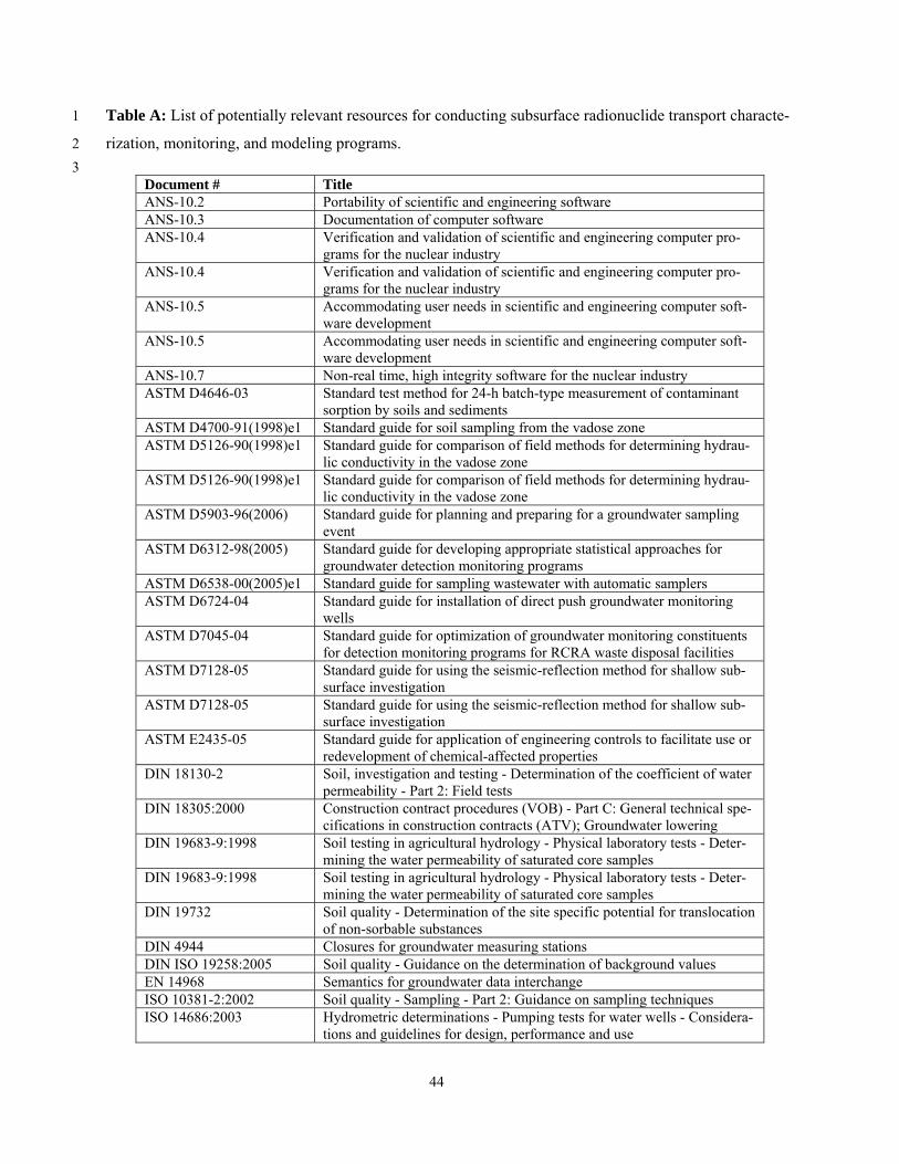
44
Table A: List of potentially relevant resources for conducting subsurface radionuclide transport characte-1
rization, monitoring, and modeling programs. 2
3 Document # Title ANS-10.2 Portability of scientific and engineering software ANS-10.3 Documentation of computer software ANS-10.4 Verification and validation of scientific and engineering computer pro-
grams for the nuclear industry ANS-10.4 Verification and validation of scientific and engineering computer pro-
grams for the nuclear industry ANS-10.5 Accommodating user needs in scientific and engineering computer soft-
ware development ANS-10.5 Accommodating user needs in scientific and engineering computer soft-
ware development ANS-10.7 Non-real time, high integrity software for the nuclear industry ASTM D4646-03 Standard test method for 24-h batch-type measurement of contaminant
sorption by soils and sediments ASTM D4700-91(1998)e1 Standard guide for soil sampling from the vadose zone ASTM D5126-90(1998)e1 Standard guide for comparison of field methods for determining hydrau-
lic conductivity in the vadose zone ASTM D5126-90(1998)e1 Standard guide for comparison of field methods for determining hydrau-
lic conductivity in the vadose zone ASTM D5903-96(2006) Standard guide for planning and preparing for a groundwater sampling
event ASTM D6312-98(2005) Standard guide for developing appropriate statistical approaches for
groundwater detection monitoring programs ASTM D6538-00(2005)e1 Standard guide for sampling wastewater with automatic samplers ASTM D6724-04 Standard guide for installation of direct push groundwater monitoring
wells ASTM D7045-04 Standard guide for optimization of groundwater monitoring constituents
for detection monitoring programs for RCRA waste disposal facilities ASTM D7128-05 Standard guide for using the seismic-reflection method for shallow sub-
surface investigation ASTM D7128-05 Standard guide for using the seismic-reflection method for shallow sub-
surface investigation ASTM E2435-05 Standard guide for application of engineering controls to facilitate use or
redevelopment of chemical-affected properties DIN 18130-2 Soil, investigation and testing - Determination of the coefficient of water
permeability - Part 2: Field tests DIN 18305:2000 Construction contract procedures (VOB) - Part C: General technical spe-
cifications in construction contracts (ATV); Groundwater lowering DIN 19683-9:1998 Soil testing in agricultural hydrology - Physical laboratory tests - Deter-
mining the water permeability of saturated core samples DIN 19683-9:1998 Soil testing in agricultural hydrology - Physical laboratory tests - Deter-
mining the water permeability of saturated core samples DIN 19732 Soil quality - Determination of the site specific potential for translocation
of non-sorbable substances DIN 4944 Closures for groundwater measuring stations DIN ISO 19258:2005 Soil quality - Guidance on the determination of background values EN 14968 Semantics for groundwater data interchange ISO 10381-2:2002 Soil quality - Sampling - Part 2: Guidance on sampling techniques ISO 14686:2003 Hydrometric determinations - Pumping tests for water wells - Considera-
tions and guidelines for design, performance and use
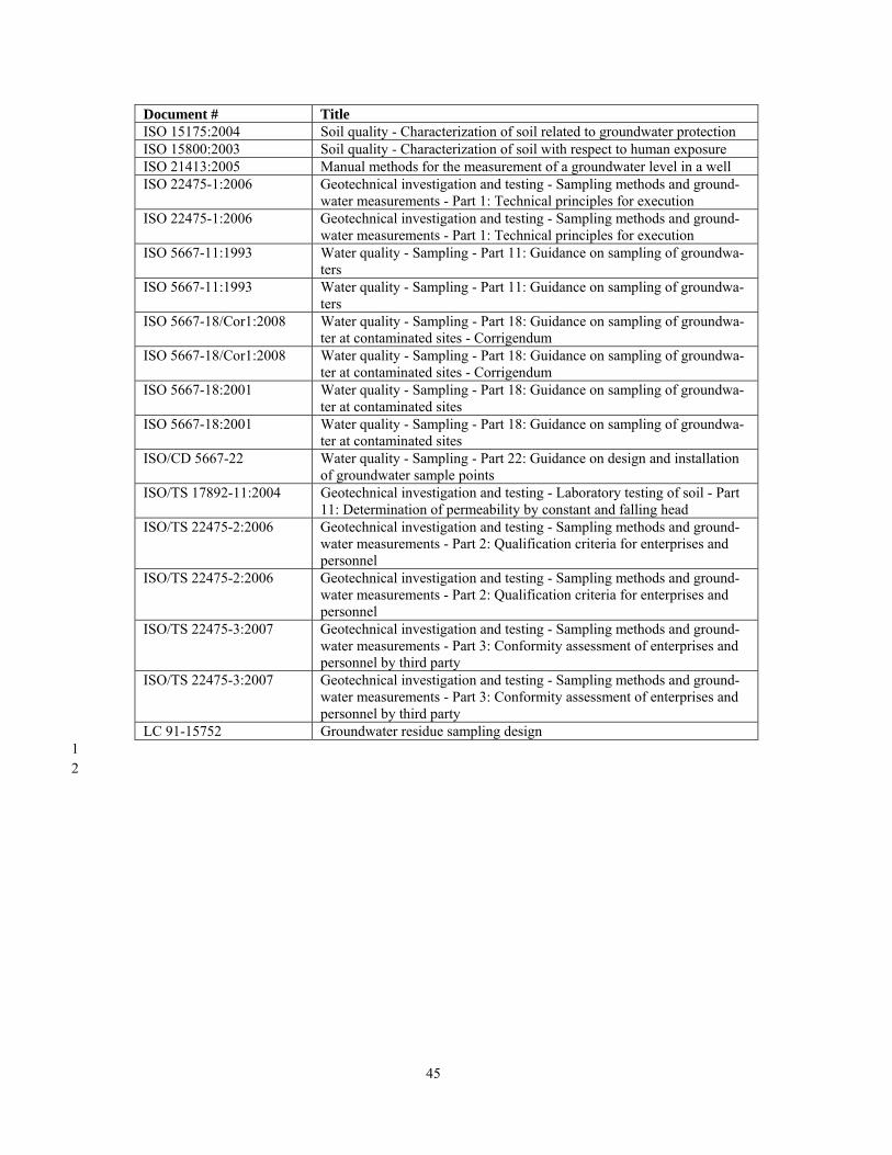
45
Document # Title ISO 15175:2004 Soil quality - Characterization of soil related to groundwater protection ISO 15800:2003 Soil quality - Characterization of soil with respect to human exposure ISO 21413:2005 Manual methods for the measurement of a groundwater level in a well ISO 22475-1:2006 Geotechnical investigation and testing - Sampling methods and ground-
water measurements - Part 1: Technical principles for execution ISO 22475-1:2006 Geotechnical investigation and testing - Sampling methods and ground-
water measurements - Part 1: Technical principles for execution ISO 5667-11:1993 Water quality - Sampling - Part 11: Guidance on sampling of groundwa-
ters ISO 5667-11:1993 Water quality - Sampling - Part 11: Guidance on sampling of groundwa-
ters ISO 5667-18/Cor1:2008 Water quality - Sampling - Part 18: Guidance on sampling of groundwa-
ter at contaminated sites - Corrigendum ISO 5667-18/Cor1:2008 Water quality - Sampling - Part 18: Guidance on sampling of groundwa-
ter at contaminated sites - Corrigendum ISO 5667-18:2001 Water quality - Sampling - Part 18: Guidance on sampling of groundwa-
ter at contaminated sites ISO 5667-18:2001 Water quality - Sampling - Part 18: Guidance on sampling of groundwa-
ter at contaminated sites ISO/CD 5667-22 Water quality - Sampling - Part 22: Guidance on design and installation
of groundwater sample points ISO/TS 17892-11:2004 Geotechnical investigation and testing - Laboratory testing of soil - Part
11: Determination of permeability by constant and falling head ISO/TS 22475-2:2006 Geotechnical investigation and testing - Sampling methods and ground-
water measurements - Part 2: Qualification criteria for enterprises and personnel
ISO/TS 22475-2:2006 Geotechnical investigation and testing - Sampling methods and ground-water measurements - Part 2: Qualification criteria for enterprises and personnel
ISO/TS 22475-3:2007 Geotechnical investigation and testing - Sampling methods and ground-water measurements - Part 3: Conformity assessment of enterprises and personnel by third party
ISO/TS 22475-3:2007 Geotechnical investigation and testing - Sampling methods and ground-water measurements - Part 3: Conformity assessment of enterprises and personnel by third party
LC 91-15752 Groundwater residue sampling design 1
2
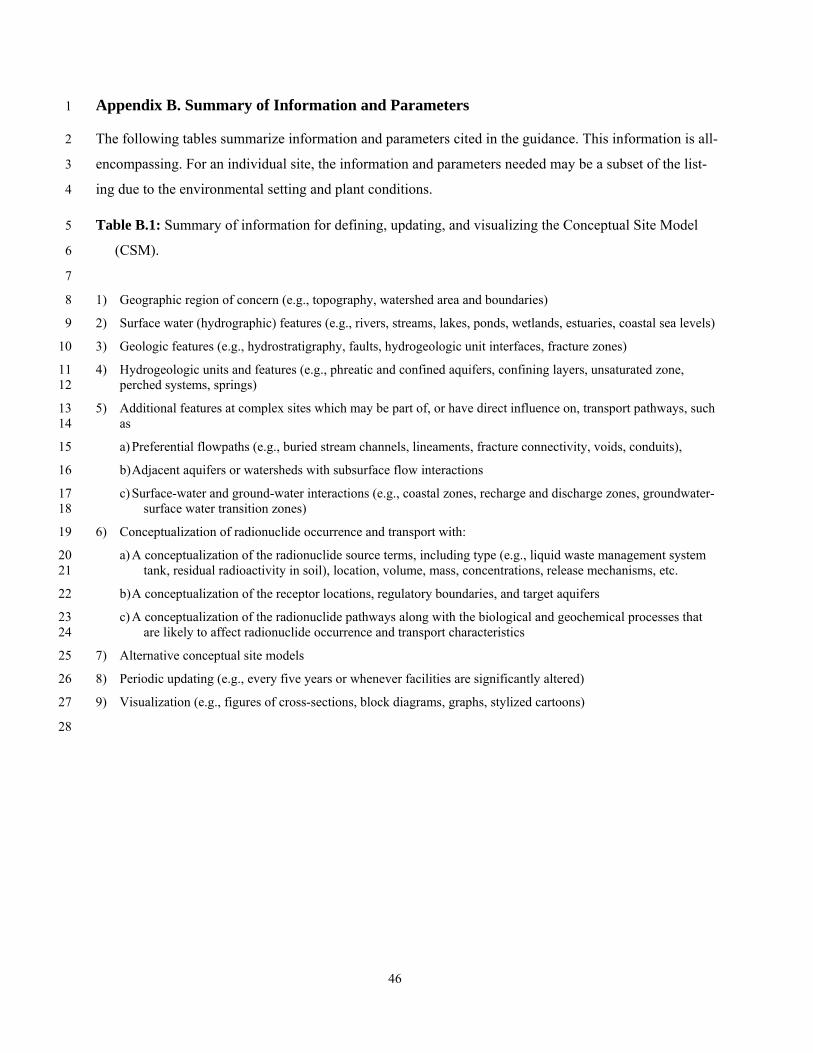
46
Appendix B. Summary of Information and Parameters 1
The following tables summarize information and parameters cited in the guidance. This information is all-2
encompassing. For an individual site, the information and parameters needed may be a subset of the list-3
ing due to the environmental setting and plant conditions. 4
Table B.1: Summary of information for defining, updating, and visualizing the Conceptual Site Model 5
(CSM). 6
7
1) Geographic region of concern (e.g., topography, watershed area and boundaries) 8
2) Surface water (hydrographic) features (e.g., rivers, streams, lakes, ponds, wetlands, estuaries, coastal sea levels) 9
3) Geologic features (e.g., hydrostratigraphy, faults, hydrogeologic unit interfaces, fracture zones) 10
4) Hydrogeologic units and features (e.g., phreatic and confined aquifers, confining layers, unsaturated zone, 11 perched systems, springs) 12
5) Additional features at complex sites which may be part of, or have direct influence on, transport pathways, such 13 as 14
a) Preferential flowpaths (e.g., buried stream channels, lineaments, fracture connectivity, voids, conduits), 15
b) Adjacent aquifers or watersheds with subsurface flow interactions 16
c) Surface-water and ground-water interactions (e.g., coastal zones, recharge and discharge zones, groundwater-17 surface water transition zones) 18
6) Conceptualization of radionuclide occurrence and transport with: 19
a) A conceptualization of the radionuclide source terms, including type (e.g., liquid waste management system 20 tank, residual radioactivity in soil), location, volume, mass, concentrations, release mechanisms, etc. 21
b) A conceptualization of the receptor locations, regulatory boundaries, and target aquifers 22
c) A conceptualization of the radionuclide pathways along with the biological and geochemical processes that 23 are likely to affect radionuclide occurrence and transport characteristics 24
7) Alternative conceptual site models 25
8) Periodic updating (e.g., every five years or whenever facilities are significantly altered) 26
9) Visualization (e.g., figures of cross-sections, block diagrams, graphs, stylized cartoons) 27
28

47
Table B.2: Summary of information and parameters required for characterizing site facility characteriza-1
tion 2
3
1) Facilities 4
a) Surface facilities (e.g., spent-fuel pools, holding ponds, condensate tanks, radwaste tanks, pipelines convey-5 ing steam or liquids containing radionuclides) 6
b) Liquid waste management systems (e.g., for newer facilities, a failure of a liquid waste management system 7 tank shall be postulated and evaluated against the effluent concentration limits given in 10 CRF Part 20. 8 These tanks should be explicitly identified in the list of facilities) 9
c) Subsurface facilities (e.g., spent-fuel pools, drains, sumps, pipes conveying steam or liquids containing ra-10 dionuclides, conduits, artificial fill, backfill, pads, foundations, and the associated vadose zone) 11
d) Engineered barriers (e.g., liners, caps, cutoff walls, leak detection systems, and interceptor wells) 12
e) Hydraulic properties of anthropogenic materials (e.g., permeable foundation backfill, permeable and im-13 permeable pipe trench backfill, impermeable foundations, foundation drains, production wells, etc). 14
f) Well construction data (e.g., drilling methods, grouted and screened intervals, screen and casing type, 15 depth, diameter, perforation, surface seals, aquifers penetrated, location, elevation, use, owner, discharge 16 rates, static hydraulic heads, and drawdown) 17
g) Abandoned wells and piezometers along with the method of abandonment and confirmation 18
2) Modifications to plant structures, systems and components affecting ground-water flow and transport 19
3) History and identification of prior abnormal releases 20
21
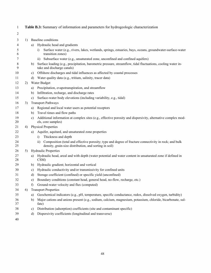
48
Table B.3: Summary of information and parameters for hydrogeologic characterization 1
2
1) Baseline conditions 3
a) Hydraulic head and gradients 4
i) Surface water (e.g., rivers, lakes, wetlands, springs, estuaries, bays, oceans, groundwater-surface-water 5 transition zones) 6
ii) Subsurface water (e.g., unsaturated zone, unconfined and confined aquifers) 7
b) Surface loading (e.g., precipitation, barometric pressure, streamflow, tidal fluctuations, cooling water in-8 take and discharge canals) 9
c) Offshore discharges and tidal influences as affected by coastal processes 10
d) Water quality data (e.g., tritium, salinity, tracer data) 11
2) Water Budget 12
a) Precipitation, evapotranspiration, and streamflow 13
b) Infiltration, recharge, and discharge rates 14
c) Surface-water body elevations (including variability, e.g., tidal) 15
3) Transport Pathways 16
a) Regional and local water users as potential receptors 17
b) Travel times and flow paths 18
c) Additional information at complex sites (e.g., effective porosity and dispersivity, alternative complex mod-19 els, core samples) 20
4) Physical Properties 21
a) Aquifer, aquitard, and unsaturated zone properties 22
i) Thickness and depth 23
ii) Composition (total and effective porosity; type and degree of fracture connectivity in rock; and bulk 24 density, grain-size distribution, and sorting in soil) 25
5) Hydraulic Properties 26
a) Hydraulic head, areal and with depth (water potential and water content in unsaturated zone if defined in 27 CSM) 28
b) Hydraulic gradient; horizontal and vertical 29
c) Hydraulic conductivity and/or transmissivity for confined units 30
d) Storage coefficient (confined) or specific yield (unconfined) 31
e) Boundary conditions (constant head, general head, no-flow, recharge, etc.) 32
f) Ground-water velocity and flux (computed) 33
6) Transport Properties 34
a) Geochemical indicators (e.g., pH, temperature, specific conductance, redox, dissolved oxygen, turbidity) 35
b) Major cations and anions present (e.g., sodium, calcium, magnesium, potassium, chloride, bicarbonate, sul-36 fate) 37
c) Distribution (adsorption) coefficients (site and contaminant specific) 38
d) Dispersivity coefficients (longitudinal and transverse) 39
40
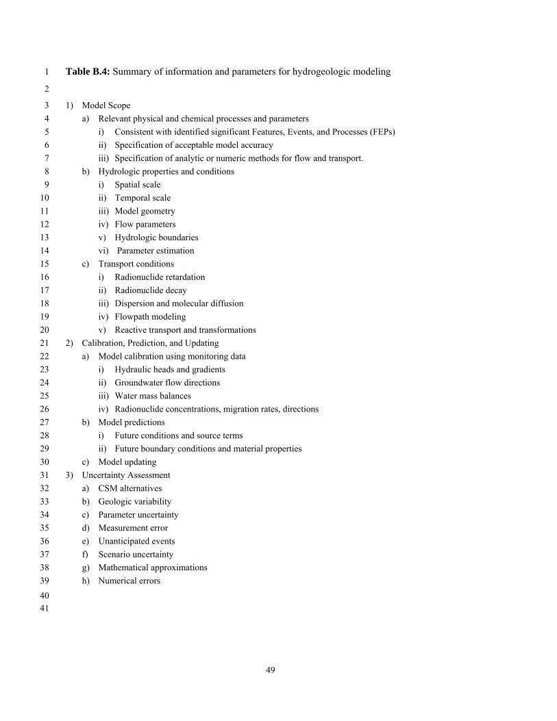
49
Table B.4: Summary of information and parameters for hydrogeologic modeling 1
2
1) Model Scope 3
a) Relevant physical and chemical processes and parameters 4
i) Consistent with identified significant Features, Events, and Processes (FEPs) 5
ii) Specification of acceptable model accuracy 6
iii) Specification of analytic or numeric methods for flow and transport. 7
b) Hydrologic properties and conditions 8
i) Spatial scale 9
ii) Temporal scale 10
iii) Model geometry 11
iv) Flow parameters 12
v) Hydrologic boundaries 13
vi) Parameter estimation 14
c) Transport conditions 15
i) Radionuclide retardation 16
ii) Radionuclide decay 17
iii) Dispersion and molecular diffusion 18
iv) Flowpath modeling 19
v) Reactive transport and transformations 20
2) Calibration, Prediction, and Updating 21
a) Model calibration using monitoring data 22
i) Hydraulic heads and gradients 23
ii) Groundwater flow directions 24
iii) Water mass balances 25
iv) Radionuclide concentrations, migration rates, directions 26
b) Model predictions 27
i) Future conditions and source terms 28
ii) Future boundary conditions and material properties 29
c) Model updating 30
3) Uncertainty Assessment 31
a) CSM alternatives 32
b) Geologic variability 33
c) Parameter uncertainty 34
d) Measurement error 35
e) Unanticipated events 36
f) Scenario uncertainty 37
g) Mathematical approximations 38
h) Numerical errors 39
40 41

50
Table B.5: Summary of information and parameters for performance-confirmation monitoring 1
2
1) Types of Monitoring Data 3
a) Hydrology 4
i) Hydraulic head 5
ii) Additional data at complex sites: 6
(1) Water flow (leak detection systems, drains, vertical borehole flow, lysimeters) 7
(2) Unsaturated zone water content, saturation, soil water potential 8
(3) Ancillary hydrologic data (precipitation, streamflow, barometric pressure, tidal stages) 9
b) Water quality 10
i) Establish baseline conditions for specific radionuclides 11
ii) Water sampling to determine compliance 12
c) Geophysical survey data to confirm CSM 13
2) Monitoring Methods 14
a) Hydrology 15
i) Depth-to-water sensors 16
ii) Methods at complex sites 17
(1) Water-level recorders 18
(2) Nested piezometers 19
(3) Borehole flowmeters 20
(4) Tensiometers, time-domain reflectometry 21
(5) Capture-type lysimeters 22
(6) Seepage runs, meters, or other appropriate techniques 23
b) Water quality 24
i) Portable or dedicated pumps, bailers 25
ii) Methods at complex sites 26
(1) In situ probes 27
(2) Gas-phase sampling 28
(3) Resistivity arrays 29
3) Monitoring Locations and Frequencies 30
a) Capable of measuring performance indicators 31
b) Ability to detect and identify subsurface release 32
c) Avoid infrastructure 33
d) At complex sites: 34
i) Located along preferential pathways 35
ii) Multiple depths 36
iii) Unsaturated zone 37
e) Upgradient and downgradient of source terms 38
f) Sufficiently often to capture intermittent or brief releases 39
40
41
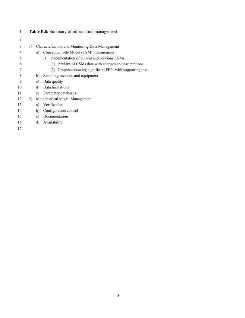
51
Table B.6: Summary of information management. 1
2
1) Characterization and Monitoring Data Management 3
a) Conceptual Site Model (CSM) management 4
i) Documentation of current and previous CSMs 5
(1) Archive of CSMs data with changes and assumptions 6
(2) Graphics showing significant FEPs with supporting text 7
b) Sampling methods and equipment 8
c) Data quality 9
d) Data limitations 10
e) Parameter databases 11
2) Mathematical Model Management 12
a) Verification 13
b) Configuration control 14
c) Documentation 15
d) Availability 16
17