american electric power’s - dolan tech · pdf file6 aep’s 1st substation battery...
TRANSCRIPT

1
American Electric PowerAmerican Electric Power’’ssEnergy StorageEnergy Storage DeploymentsDeployments
2
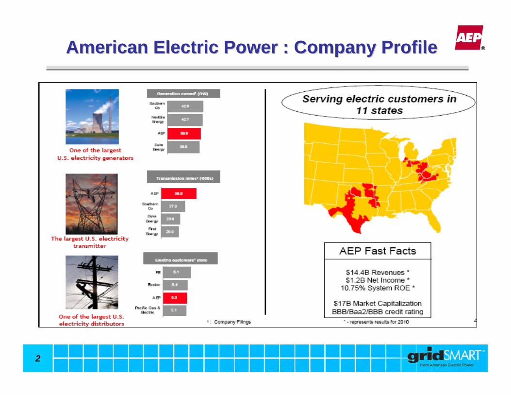
American Electric Power : Company ProfileAmerican Electric Power : Company Profile

3
The Evolution of the Electric Utility SystemThe Evolution of the Electric Utility System
Before Smart Grid:One-way power flow, simple interactions, limited sources of renewable generation
After Smart Grid:Two-way power flow, multi-stakeholder interactions, increased penetration of renewable generation
Adapted from EPRI Presentation by Joe HughesNIST Standards Workshop
April 28, 2008
4
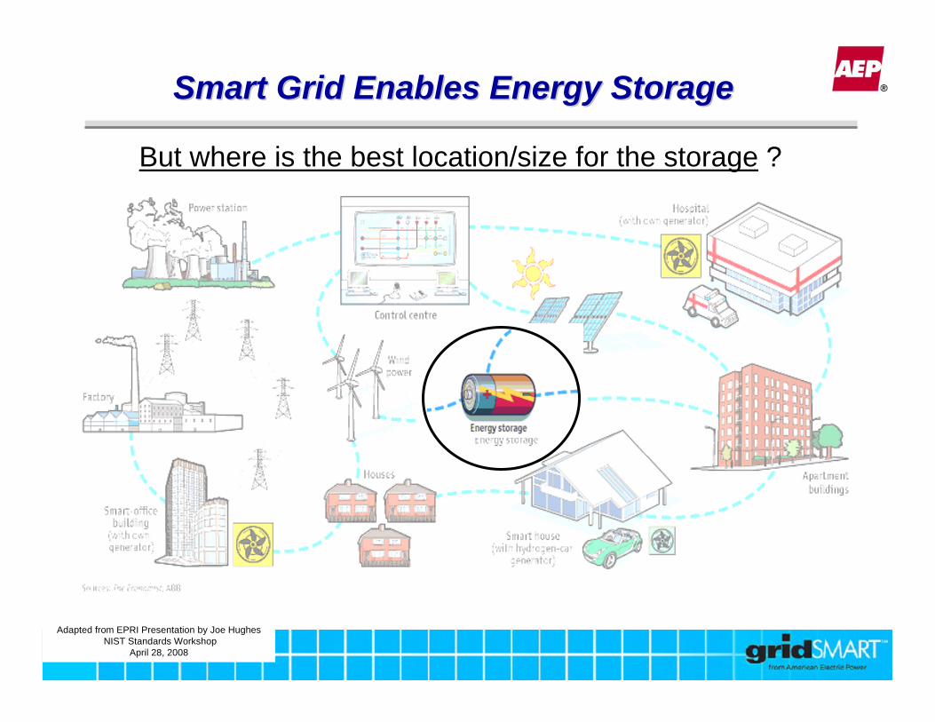
Smart Grid Enables Energy StorageSmart Grid Enables Energy Storage
Adapted from EPRI Presentation by Joe HughesNIST Standards Workshop
April 28, 2008
But where is the best location/size for the storage ?

5
Energy Storage OptionsEnergy Storage Options
6
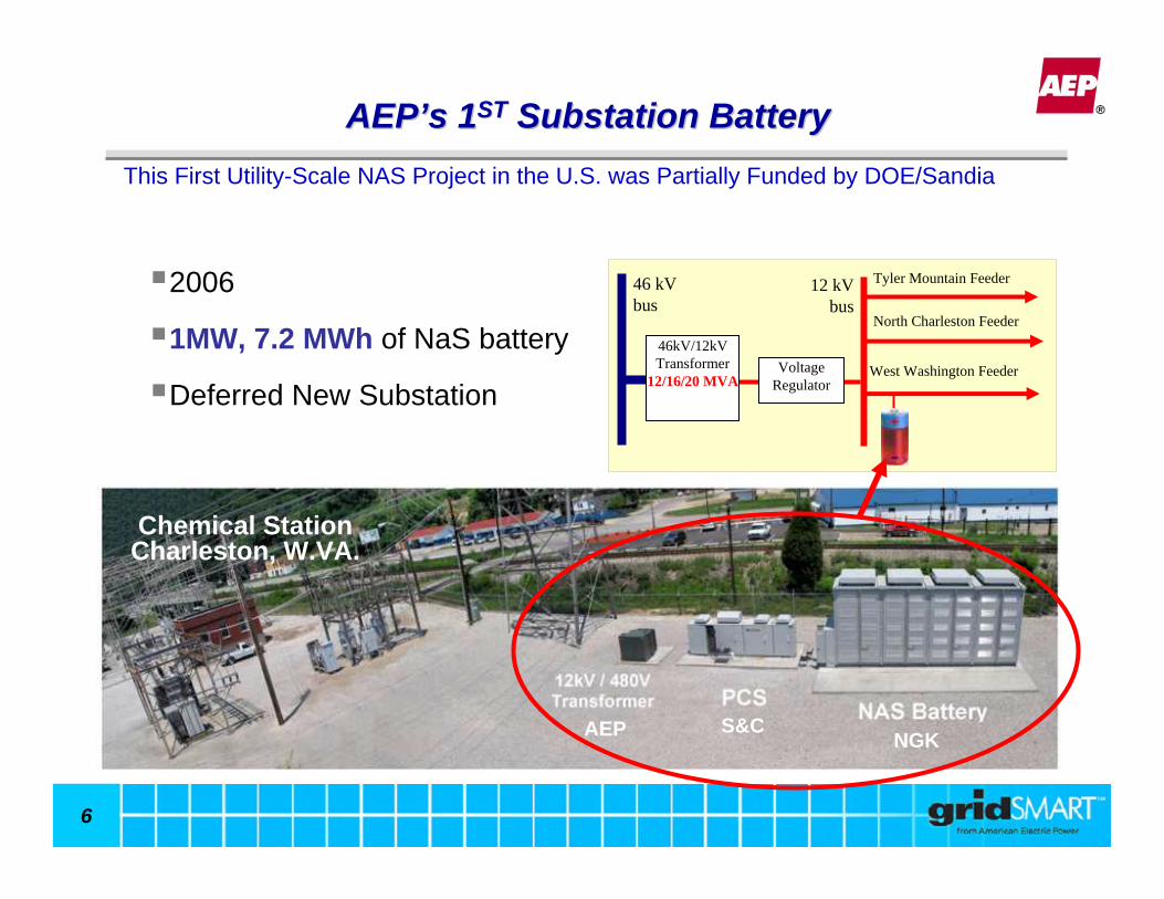
AEPAEP’’s 1s 1STST Substation BatterySubstation Battery
2006
1MW, 7.2 MWh of NaS battery
Deferred New Substation
Tyler Mountain Feeder12 kV bus
North Charleston Feeder
West Washington FeederVoltage Regulator
46kV/12kV Transformer
12/16/20 MVA
46 kV bus
This First Utility-Scale NAS Project in the U.S. was Partially Funded by DOE/Sandia
NGKS&CAEP
Chemical StationCharleston, W.VA.

7
AEP 2006 Project – Peak Shaving
• Scheduled trapezoidal Charge & Discharge profiles
• Summer Month Peak Days
• Improved the feeder load factor by 5% (from 75% to 80%) + 1.2 MW Charge
- 1.0 MW Discharge
2007
2006
2008Three SuccessfulYears of
Peak Shaving
8
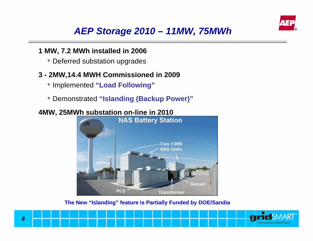
AEP Storage 2010 – 11MW, 75MWh
1 MW, 7.2 MWh installed in 2006• Deferred substation upgrades
3 - 2MW,14.4 MWH Commissioned in 2009• Implemented “Load Following”
• Demonstrated “Islanding (Backup Power)”
4MW, 25MWh substation on-line in 2010
The New “Islanding” feature is Partially Funded by DOE/Sandia
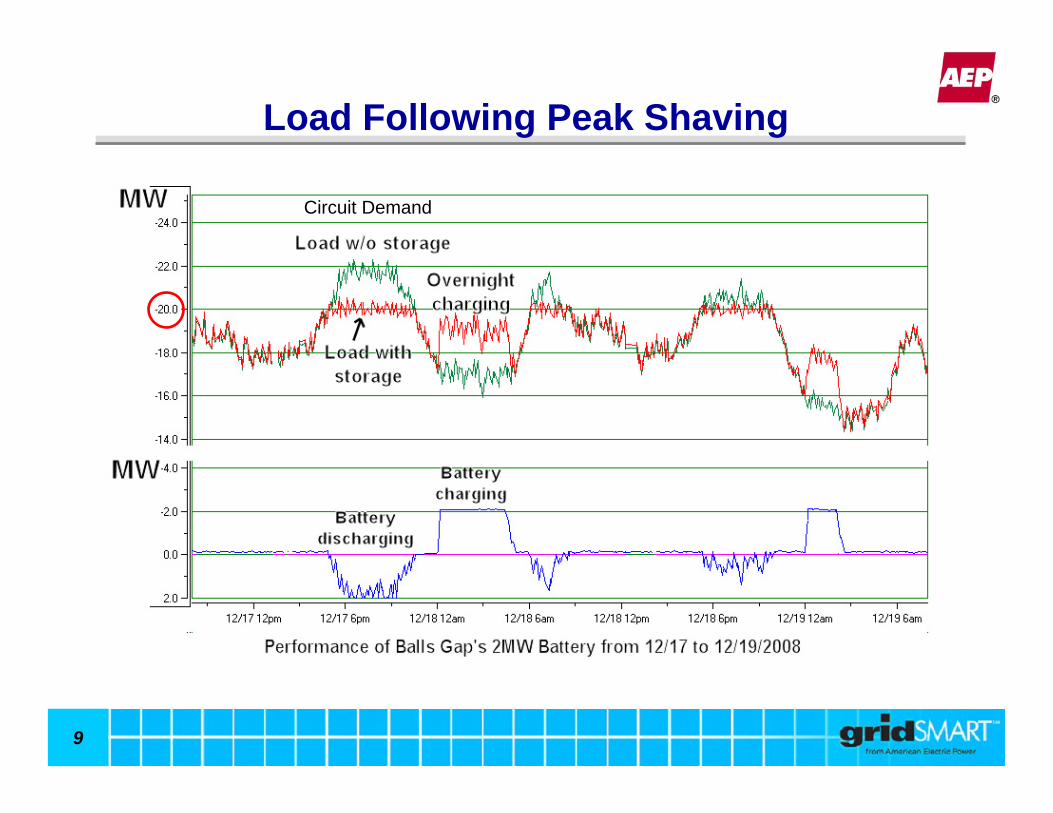
9
Load Following Peak Shaving
Circuit Demand
10
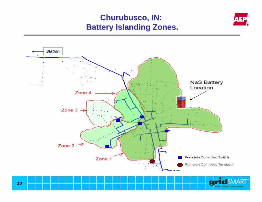
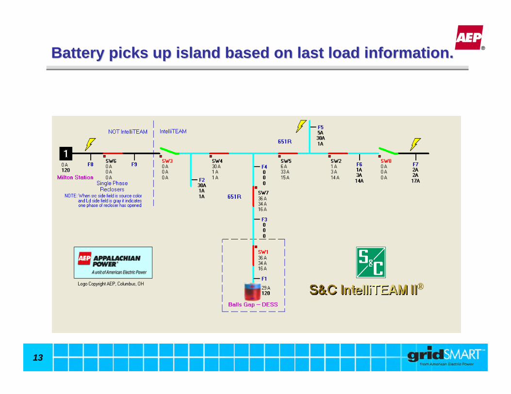
Churubusco, IN:Churubusco, IN:Battery Islanding Zones.Battery Islanding Zones.
Station
11
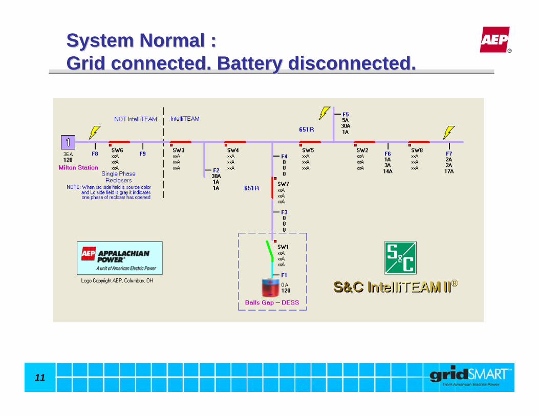
System Normal :System Normal :Grid connected. Battery disconnected.Grid connected. Battery disconnected.
12
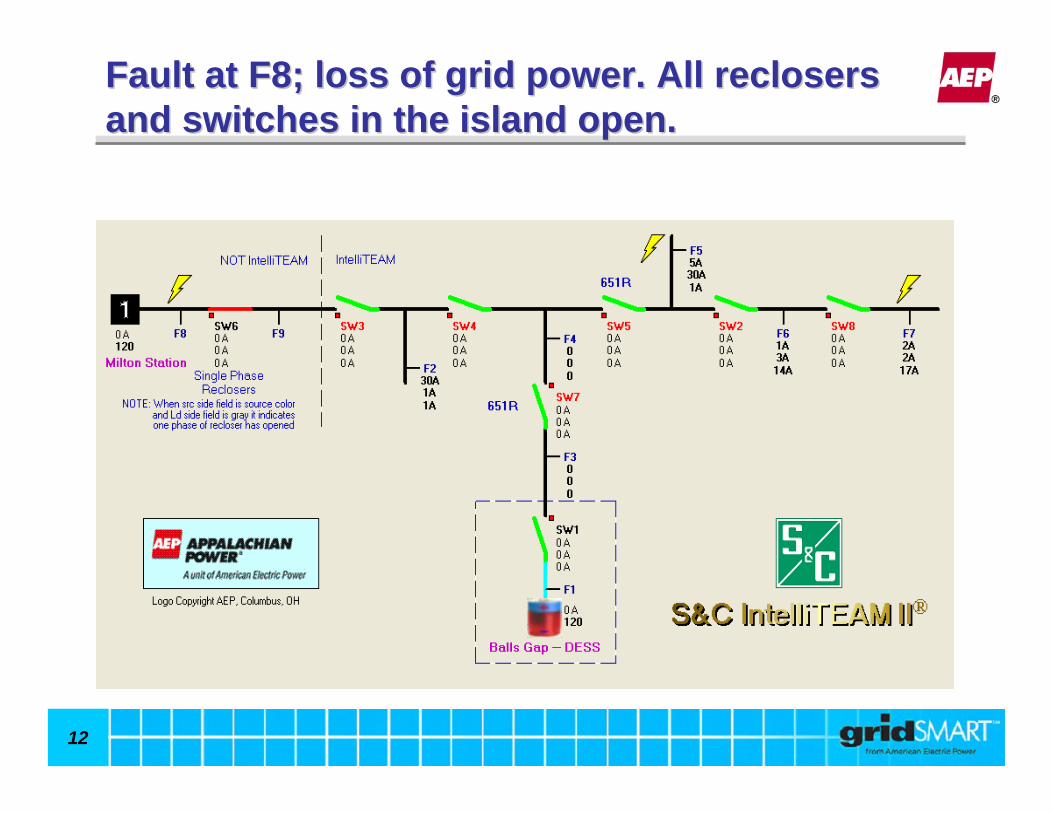
Fault at F8; loss of grid power. All reclosers Fault at F8; loss of grid power. All reclosers and switches in the island open.and switches in the island open.
13
Battery picks up island based on last load information.Battery picks up island based on last load information.

14
Grid power restored.Grid power restored.

15
Battery disconnected. Load connected back to the grid.Battery disconnected. Load connected back to the grid.

16
Islanding (Backup Power) EventsIslanding (Backup Power) Events
Mar 2011Nov 2010Dec 2009DateElectrical FaultVehicle AccidentIce StormCause of Outage
10 hours1hr 17 mins48 hoursDuration on Backup Power
70070025Customers on Backup PowerMilton, WVMilton, WVMilton, WVLocation
Event 3Event 2Event 1

17
Battery used for Voltage SupportBattery used for Voltage Support
18
Community Energy Storage (CES)Community Energy Storage (CES)
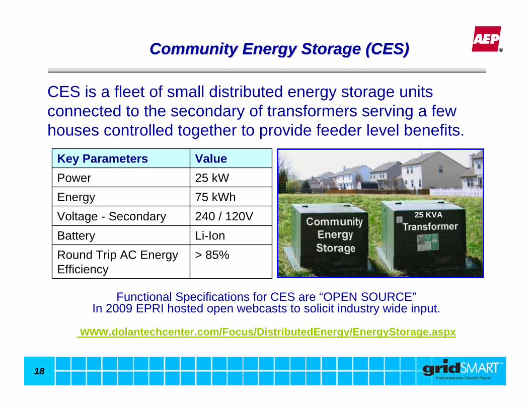
CES is a fleet of small distributed energy storage units connected to the secondary of transformers serving a few houses controlled together to provide feeder level benefits.
240 / 120VVoltage - SecondaryLi-IonBattery > 85%Round Trip AC Energy
Efficiency
75 kWh Energy25 kWPowerValueKey Parameters
Functional Specifications for CES are “OPEN SOURCE”In 2009 EPRI hosted open webcasts to solicit industry wide input.
www.dolantechcenter.com/Focus/DistributedEnergy/EnergyStorage.aspx
25 KVA

19
CES CES –– Benefits to the CustomerBenefits to the Customer
Local Benefits:1) Backup Power2) Renewable Integration3) Voltage correction
Substation
Power LinesCommunication and Control Links
CES
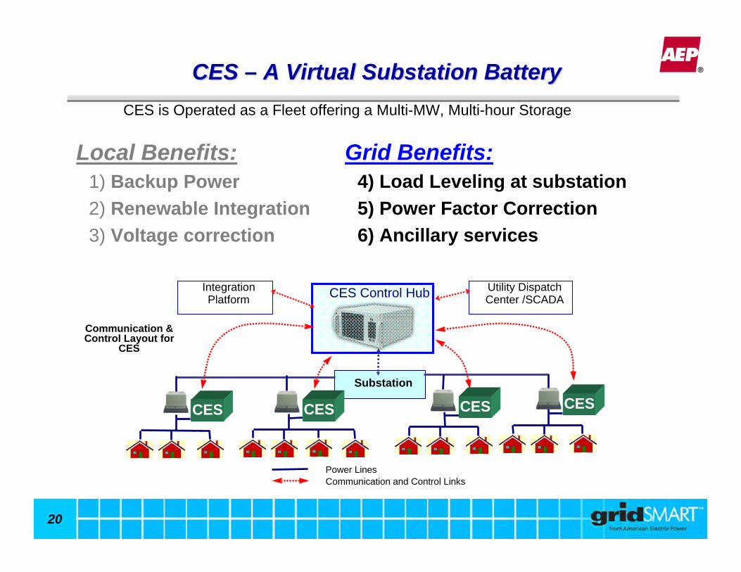
CES is Operated as a Fleet offering a Multi-MW, Multi-hour Storage
20
CES CES –– A Virtual Substation BatteryA Virtual Substation Battery
Communication & Control Layout for
CES
Utility Dispatch Center /SCADACES Control Hub
Substation
Power LinesCommunication and Control Links
Integration Platform
CES CESCESCES
CES is Operated as a Fleet offering a Multi-MW, Multi-hour Storage
Grid Benefits:4) Load Leveling at substation5) Power Factor Correction6) Ancillary services
Local Benefits:1) Backup Power2) Renewable Integration3) Voltage correction

21
CES CES –– NE Columbus Project Benefits.NE Columbus Project Benefits.
22
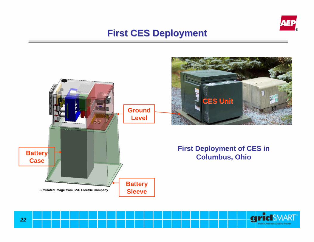
First Deployment of CES in Columbus, Ohio
Battery Sleeve
Battery Case
First CES DeploymentFirst CES Deployment
CES UnitCES Unit
Simulated Image from S&C Electric Company
Ground Level
23
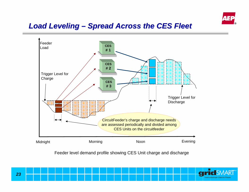
Morning Noon EveningMidnight
Trigger Level for Discharge
Trigger Level for Charge
CircuitFeeder’s charge and discharge needs are assessed periodically and divided among
CES Units on the circuitfeeder
Feeder Load CES
# 1
CES# 2
CES# 3
Feeder level demand profile showing CES Unit charge and discharge
Load Leveling Load Leveling –– Spread Across the CES FleetSpread Across the CES Fleet
24
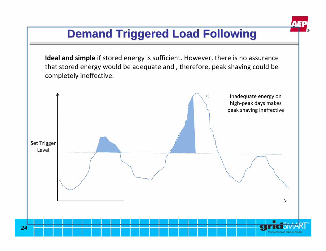
Demand Triggered Load FollowingDemand Triggered Load Following
Ideal and simple if stored energy is sufficient. However, there is no assurance that stored energy would be adequate and , therefore, peak shaving could be completely ineffective.
Set Trigger Level
Inadequate energy on high‐peak days makes peak shaving ineffective
25
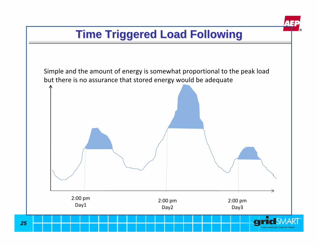
Time Triggered Load FollowingTime Triggered Load Following
2:00 pm Day1
2:00 pm Day2
2:00 pm Day3
Simple and the amount of energy is somewhat proportional to the peak load but there is no assurance that stored energy would be adequate

26
Time Triggered Discharge ParametersTime Triggered Discharge Parameters
• Set Points:– Start Time (same for all days)– Minimum Demand below which no energy should be discharged
2:00 pm Day1
2:00 pm Day2
2:00 pm Day3
No Discharge on Low demands
Minimum Demand at for discharge
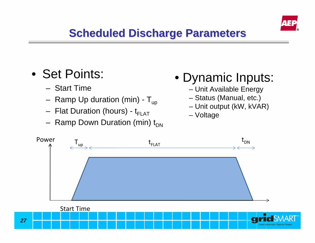
27
• Set Points:– Start Time– Ramp Up duration (min) - Tup
– Flat Duration (hours) - tFLAT
– Ramp Down Duration (min) tDN
Scheduled Discharge ParametersScheduled Discharge Parameters
Start Time
Tup tFLATtDNPower
• Dynamic Inputs:– Unit Available Energy– Status (Manual, etc.)– Unit output (kW, kVAR)– Voltage

28
Power
Power
Power
Case 1 – Reported Available energy is sufficient
Case 2 – Available energy is not sufficient
1.Planner Option (Keep Duration, reduce Power)
2.Dispatcher Option (Keep Power, reduce duration)
Scheduled Discharge OptionsScheduled Discharge Options
29
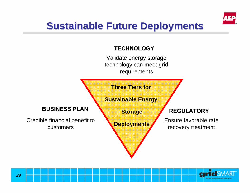
Sustainable Future DeploymentsSustainable Future Deployments
Three Tiers for
Sustainable Energy
Storage
Deployments
TECHNOLOGYTECHNOLOGYValidate energy storage
technology can meet grid requirements
Credible financial benefit to customers
Ensure favorable rate recovery treatment
BUSINESS PLANBUSINESS PLAN REGULATORYREGULATORY

30
ConclusionConclusion
• Successful deployment of Energy Storage Systems
• AEP’s current Energy Storage strategy is focused primarily on Community Energy Storage.
• Energy Storage System Cost must reduce significantly to become economically justifiable for utility deployment.
• Market predictions indicate that near-term costs for energy storage may broaden deployment opportunities.