ambis point rodding wire systeambisengineering.co.uk/pointroddingwiresystem_pt1.pdfsignal status...
TRANSCRIPT
AMBIS Point Rodding & Wire System
Part One (of Three Parts)
Introduction to the Prototype
Introduction
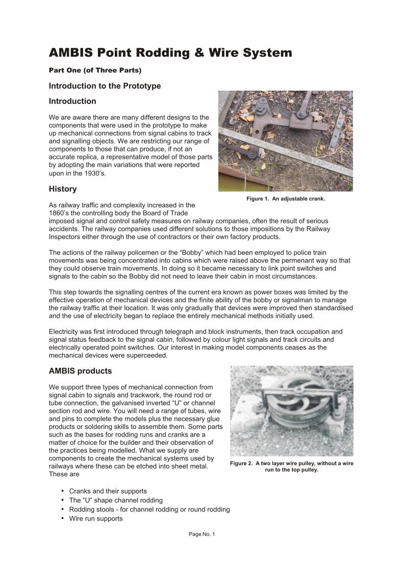
We are aware there are many different designs to thecomponents that were used in the prototype to makeup mechanical connections from signal cabins to track and signalling objects. We are restricting our range ofcomponents to those that can produce, if not anaccurate replica, a representative model of those parts by adopting the main variations that were reported
upon in the 1930’s.
History
As railway traffic and complexity increased in the1860’s the controlling body the Board of Tradeimposed signal and control safety measures on railway companies, often the result of seriousaccidents. The railway companies used different solutions to those impositions by the RailwayInspectors either through the use of contractors or their own factory products.
The actions of the railway policemen or the “Bobby” which had been employed to police trainmovements was being concentrated into cabins which were raised above the permenant way so thatthey could observe train movements. In doing so it became necessary to link point switches andsignals to the cabin so the Bobby did not need to leave their cabin in most circumstances.
This step towards the signalling centres of the current era known as power boxes was limited by theeffective operation of mechanical devices and the finite ability of the bobby or signalman to managethe railway traffic at their location. It was only gradually that devices were improved then standardisedand the use of electricity began to replace the entirely mechanical methods initially used.
Electricity was first introduced through telegraph and block instruments, then track occupation andsignal status feedback to the signal cabin, followed by colour light signals and track circuits andelectrically operated point switches. Our interest in making model components ceases as themechanical devices were superceeded.
AMBIS products
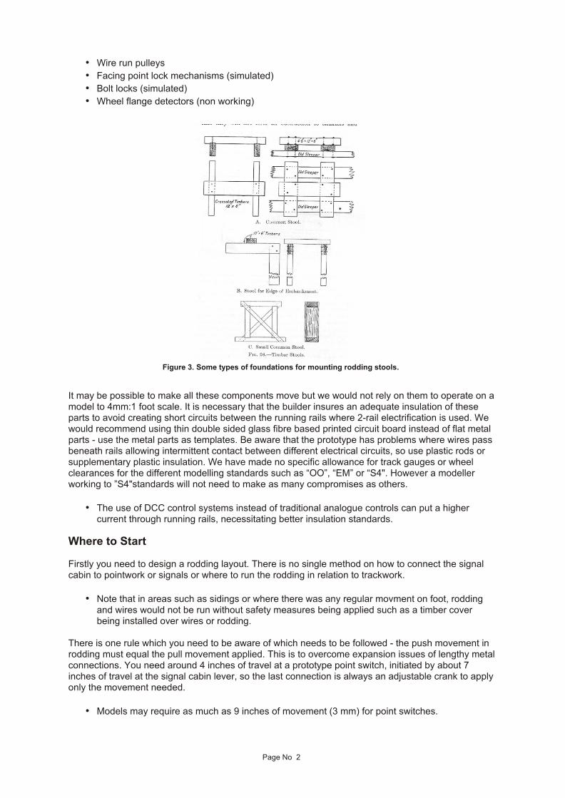
We support three types of mechanical connection fromsignal cabin to signals and trackwork, the round rod ortube connection, the galvanised inverted “U” or channelsection rod and wire. You will need a range of tubes, wireand pins to complete the models plus the necessary glueproducts or soldering skills to assemble them. Some parts such as the bases for rodding runs and cranks are amatter of choice for the builder and their observation ofthe practices being modelled. What we supply arecomponents to create the mechanical systems used byrailways where these can be etched into sheet metal.These are
• Cranks and their supports
• The “U” shape channel rodding
• Rodding stools - for channel rodding or round rodding
• Wire run supports
Page No. 1
Figure 1. An adjustable crank.
Figure 2. A two layer wire pulley, without a wire run to the top pulley.
• Wire run pulleys
• Facing point lock mechanisms (simulated)
• Bolt locks (simulated)
• Wheel flange detectors (non working)
It may be possible to make all these components move but we would not rely on them to operate on a model to 4mm:1 foot scale. It is necessary that the builder insures an adequate insulation of theseparts to avoid creating short circuits between the running rails where 2-rail electrification is used. Wewould recommend using thin double sided glass fibre based printed circuit board instead of flat metalparts - use the metal parts as templates. Be aware that the prototype has problems where wires passbeneath rails allowing intermittent contact between different electrical circuits, so use plastic rods orsupplementary plastic insulation. We have made no specific allowance for track gauges or wheelclearances for the different modelling standards such as “OO”, “EM” or “S4". However a modellerworking to ”S4"standards will not need to make as many compromises as others.
• The use of DCC control systems instead of traditional analogue controls can put a highercurrent through running rails, necessitating better insulation standards.
Where to Start
Firstly you need to design a rodding layout. There is no single method on how to connect the signalcabin to pointwork or signals or where to run the rodding in relation to trackwork.
• Note that in areas such as sidings or where there was any regular movment on foot, roddingand wires would not be run without safety measures being applied such as a timber coverbeing installed over wires or rodding.
There is one rule which you need to be aware of which needs to be followed - the push movement inrodding must equal the pull movement applied. This is to overcome expansion issues of lengthy metal connections. You need around 4 inches of travel at a prototype point switch, initiated by about 7inches of travel at the signal cabin lever, so the last connection is always an adjustable crank to applyonly the movement needed.
• Models may require as much as 9 inches of movement (3 mm) for point switches.
Page No 2
Figure 3. Some types of foundations for mounting rodding stools.
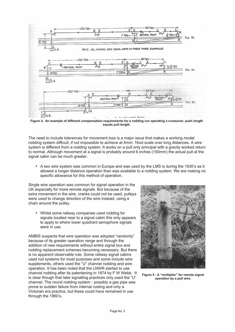
The need to include tolerences for movement loss is a major issue that makes a working modelrodding system difficult, if not impossible to achieve at 4mm: 1foot scale over long distances. A wiresystem is different from a rodding system. It works on a pull only principal with a gravity worked return to normal. Although movement at a signal is probably around 6 inches (150mm) the actual pull at thesignal cabin can be much greater.
• A two wire system was common in Europe and was used by the LMS is during the 1930’s as itallowed a longer distance operation than was available to a rodding system. We are making no specific allowance for this method of operation.
Single wire operation was common for signal operation in theUK especially for more remote signals. But because of theextra movement in the wire, cranks could not be used, pulleyswere used to change direction of the wire instead, using achain around the pulley.
• Whilst some railway companies used rodding forsignals located near to a signal cabin this only appearsto apply to where lower quadrant semaphore signalswere in use.
AMBIS suspects that wire operation was adopted “randomly”because of its greater operation range and through theaddition of new requirements without entire signal box androdding replacement schemes becoming necessary. But there is no apparent observable rule. Some railway signal cabinsused rod systems for most purposes and some include wiresupplements, others used the “U” channel rodding and wireoperation. It has been noted that the LNWR started to usechannel rodding after its patentening in 1874 by F W Webb. It is clear though that later signalling practices only used the “U”channel. The round rodding system - possibly a gas pipe wasprone to sudden failure from internal rusting and only aVictorian era practice, but these could have remained in usethrough the 1960’s.
Page No 3
Figure 4. An example of different compensation requirements for a rodding run operating a crossover, push lengthequals pull length.
Figure 5 - A “multiplier” for remote signaloperation by a pull wire.

• We have no evidence that “U”channel was used for signals.
The distance from a signal cabin that devices were allowed increases over time. As labour becamemore expensive, railway traffic may have reduced and/or to reduce communication needs. Somerailways such as the Midland Railway/LMS centralised signalling operations from perhaps three smallsignal cabins for one railway station, down to one with perhaps a ground mounted lever frameunlocked for use by the signalman for more distant pointwork.
Board of Trade limitations on the distance of mechanically worked facing points from signal cabins.
Year 1874 1877 1885 1900 1908 1925
Distance (yards) 120 150 180 200 250 350
Scale Distance(1:76.2) (approximate)
5 feet 6 feet 7 feet 8 feet 10 feet 14 feet
Many railway models will not be sufficiently long to necessiatate the use of more than one signal cabin to overcome any distance limitation. For modellers other factors are likely to determine the use ofmore than one signal cabin.
As a rule of thumb rodding supports would occur at about 8 feet intervals (2.4m) for a straight run,reducing down to 5-6 feet (1.6 to 1.8m) for curves. Tables showing adjustment requirements suggestruns of up to 1100 feet were commonplace for rodding by 1946 (about 14 feet or 4.2m at 4mm:1 footscale).
• Note that prototype curves are much larger than commonly found on models, rodding will betoo inefficient to operate around model “minimum radius” curves. So use straightish runs joined by cranks on tight curves.
• Similarly for signal wires these could be enabled to negotiate tighter curves by usinghorizontally mounted pulleys
Wire runs were supported on posts at about at varying intervals depending upon the number of wirescarried - about 24 feet (about 9.2m) intervals would be an average distance but for a single wire thiscould be 30 feet (11m).
For distant signals located perhaps 2000 yards from a signal cabin about 24 inches of pull would berequired at the signal lever using a pulley multiplication system within the signal cabin, whereasnearer signals may be directly linked to the lever. Some railways used extra balance weights to“multiply” the effect of a signal lever for wire mounted remote signals. In Scotland where main lineswere often single lines this resulted in some complex arrangements.
Observe Prototype SignallingPractices
Unless you are working with a prototype ofwhich you have a signal box diagram you willneed to create one from which the roddingsystem will need to follow. One way of doingthis will be to start from the most remote deviceyou need to operate remotely by a signalmanthen work out a route back to the signal cabinadding other device links en-route.
Runs can cross trackwork under rails, betweensleepers, but rarely did so near to otherequipment such as point switches andcrossings.
Page No 4
Figure 6 A mechanical lock using tappets, between signalcabins or to a ground frame from a signal cabin

Each rodding installation will probably be basedupon the company practices, the whims of theindividual engineer and local circumstances. Forexample it appears the NER had a signal for anyconceivable train movement whereas otherrailways e.g. Midland Railway seemed to limit theextent of facing points and ground signals it used,may have widely relied upon flags for shuntingmovements close to a signal box and used rodsto operate its lower quadrant signals.
There are some devices not commonly modelledwhich would require levers in a signal cabin and a connection to their location. These include:-
1. DetonatorsWarning devices set off by the pressure of a wheel annoucing the approach of a signal to a traindriver in dense fog (we have no intention of producing any components for this specific purpose).
2. GongsThese were used as a safety device for warning purposes, such as within tunnels preceedingpointwork such as at London, Kings Cross Station.
3. Mechanical locks between signal boxes forcommon signals or points. These were common inareas of dense signal cabins where their blocksections overlap but can also be used betweenground frames and signal cabins. This was apractice known to be used by the Midland Railwaybefore electric interlocking became available.
• see Figure 6 for an example
4. Train on track detectors and treadles not directly linked to point switches. These devices could belinked mechanically to signal boxes although anelectrical connection would be more commonplace. This device could be required where the signalman could not see such as, the distant end of a loop line where a train could block the use of an adjacenttrack; if an engine release crossover was fouled; or the end of a bay platform obsured byan awningwhere stock could have been shunted and thenforgotten by a signalman.
A treadle using a counterbalance would normally be raised to rail head height, so that any passingstock would depress the treadle and thereby indicate the occupancy of the track by a railway vehicle.It must be able to detect at least one wheel so that there has to be an allowance for different length ofrolling stock being used.
• See Figure 7 for a section through a balanced bar
The treadle needs to span more than the longest distance between any wheels in a train. A rule ofthumb based upon coach designs is as follows:-
Shorter bogie coaches (e.g. 48 feet long) with long wheelbase bogies (e.g. 10 feet) - 21 feetShorter bogie coaches (e.g. 48 feet long) with short wheelbase bogies (e.g. 8 feet) - 26 feetLonger coaches (e.g. 61 ft 6 inches) 35 feetArticulated coaches …40 feet
Page No 5
Figure 7. A balanced bar treadle design
Figure 8. Epping Station, before electrification. Adetector fitted to both lines, the signal cabin was
located at the other end of the platforms. Here the linecontinued to Ongar and changed to a single track.
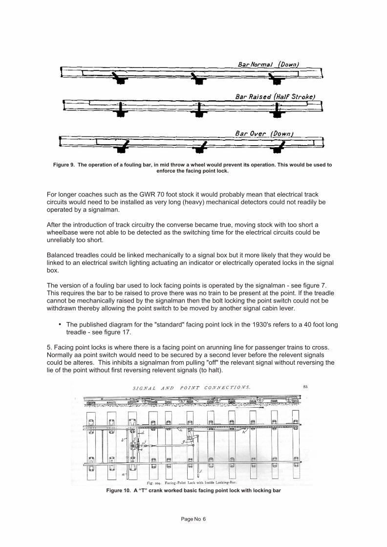
For longer coaches such as the GWR 70 foot stock it would probably mean that electrical trackcircuits would need to be installed as very long (heavy) mechanical detectors could not readily beoperated by a signalman.
After the introduction of track circuitry the converse became true, moving stock with too short awheelbase were not able to be detected as the switching time for the electrical circuits could beunreliably too short.
Balanced treadles could be linked mechanically to a signal box but it more likely that they would belinked to an electrical switch lighting actuating an indicator or electrically operated locks in the signalbox.
The version of a fouling bar used to lock facing points is operated by the signalman - see figure 7.This requires the bar to be raised to prove there was no train to be present at the point. If the treadlecannot be mechanically raised by the signalman then the bolt locking the point switch could not bewithdrawn thereby allowing the point switch to be moved by another signal cabin lever.
• The published diagram for the "standard" facing point lock in the 1930's refers to a 40 foot longtreadle - see figure 17.
5. Facing point locks is where there is a facing point on arunning line for passenger trains to cross.Normally aa point switch would need to be secured by a second lever before the relevent signalscould be alteres. This inhibits a signalman from pulling "off" the relevant signal without reversing thelie of the point without first reversing relevent signals (to halt).
Page No 6
Figure 9. The operation of a fouling bar, in mid throw a wheel would prevent its operation. This would be used toenforce the facing point lock.
Figure 10. A “T” crank worked basic facing point lock with locking bar
It was common that an unbalanced treadle(one raised by a lever) was linked to this locklever so that should a train be traversing thatpointwork the signalman would be inhibitedfrom releasing the facing point lock.
Later signalling practices did generallyreplace the wheel detector with an electrictrack circuit.
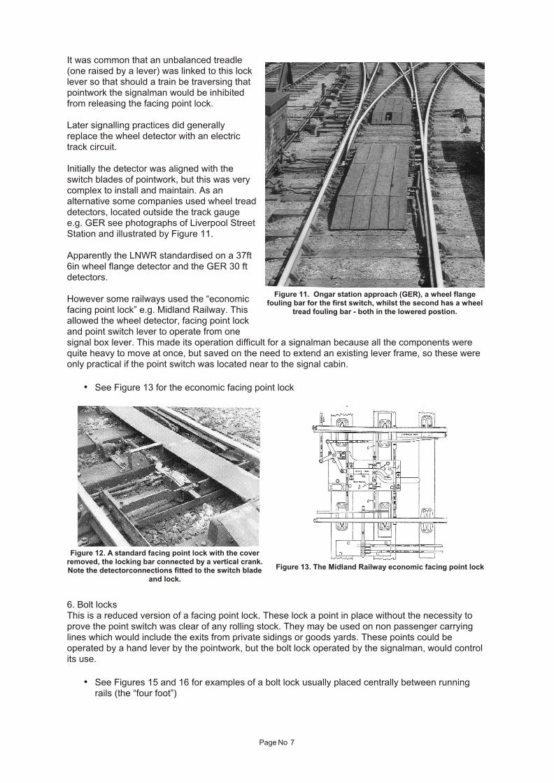
Initially the detector was aligned with theswitch blades of pointwork, but this was verycomplex to install and maintain. As analternative some companies used wheel tread detectors, located outside the track gaugee.g. GER see photographs of Liverpool Street Station and illustrated by Figure 11.
Apparently the LNWR standardised on a 37ft6in wheel flange detector and the GER 30 ftdetectors.
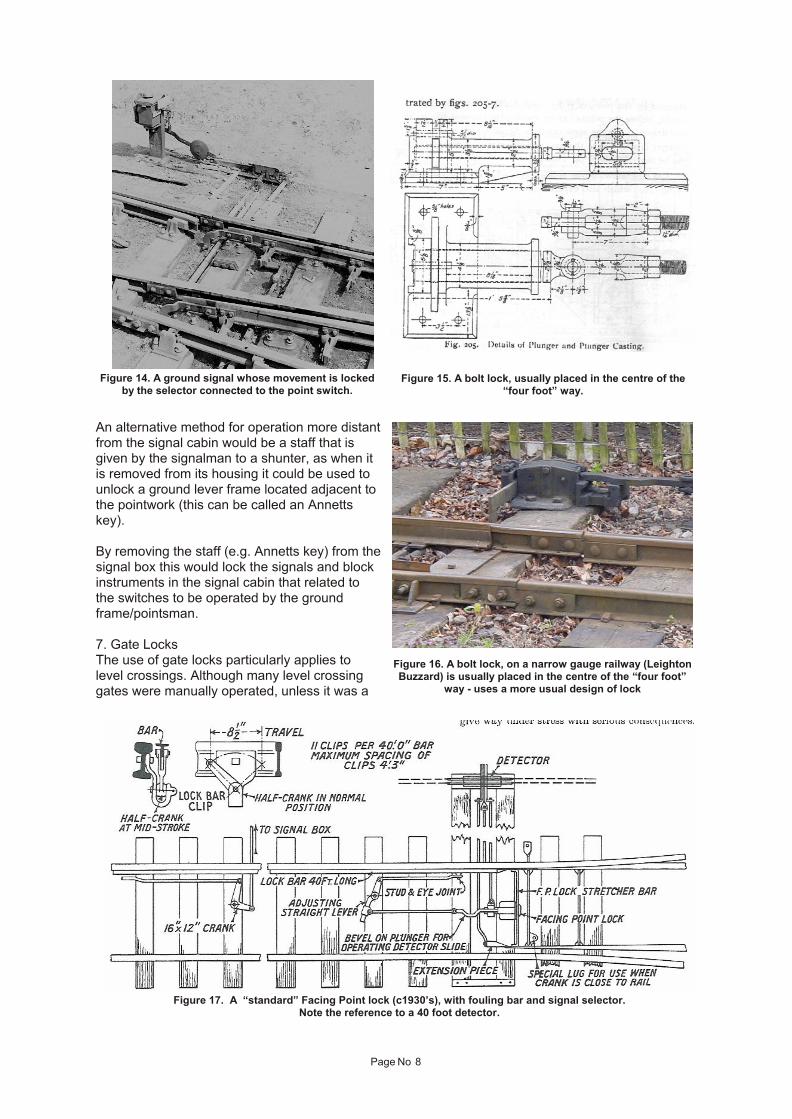
However some railways used the “economicfacing point lock” e.g. Midland Railway. Thisallowed the wheel detector, facing point lockand point switch lever to operate from onesignal box lever. This made its operation difficult for a signalman because all the components werequite heavy to move at once, but saved on the need to extend an existing lever frame, so these wereonly practical if the point switch was located near to the signal cabin.
• See Figure 13 for the economic facing point lock
6. Bolt locksThis is a reduced version of a facing point lock. These lock a point in place without the necessity toprove the point switch was clear of any rolling stock. They may be used on non passenger carryinglines which would include the exits from private sidings or goods yards. These points could beoperated by a hand lever by the pointwork, but the bolt lock operated by the signalman, would controlits use.
• See Figures 15 and 16 for examples of a bolt lock usually placed centrally between runningrails (the “four foot”)
Page No 7
Figure 11. Ongar station approach (GER), a wheel flangefouling bar for the first switch, whilst the second has a wheel
tread fouling bar - both in the lowered postion.
Figure 12. A standard facing point lock with the coverremoved, the locking bar connected by a vertical crank. Note the detectorconnections fitted to the switch blade
and lock.
Figure 13. The Midland Railway economic facing point lock
An alternative method for operation more distant from the signal cabin would be a staff that isgiven by the signalman to a shunter, as when itis removed from its housing it could be used tounlock a ground lever frame located adjacent tothe pointwork (this can be called an Annettskey).
By removing the staff (e.g. Annetts key) from the signal box this would lock the signals and blockinstruments in the signal cabin that related tothe switches to be operated by the groundframe/pointsman.
7. Gate LocksThe use of gate locks particularly applies tolevel crossings. Although many level crossinggates were manually operated, unless it was a
Page No 8
Figure 17. A “standard” Facing Point lock (c1930’s), with fouling bar and signal selector.Note the reference to a 40 foot detector.
Figure 14. A ground signal whose movement is lockedby the selector connected to the point switch.
Figure 15. A bolt lock, usually placed in the centre of the“four foot” way.
Figure 16. A bolt lock, on a narrow gauge railway (LeightonBuzzard) is usually placed in the centre of the “four foot”
way - uses a more usual design of lock
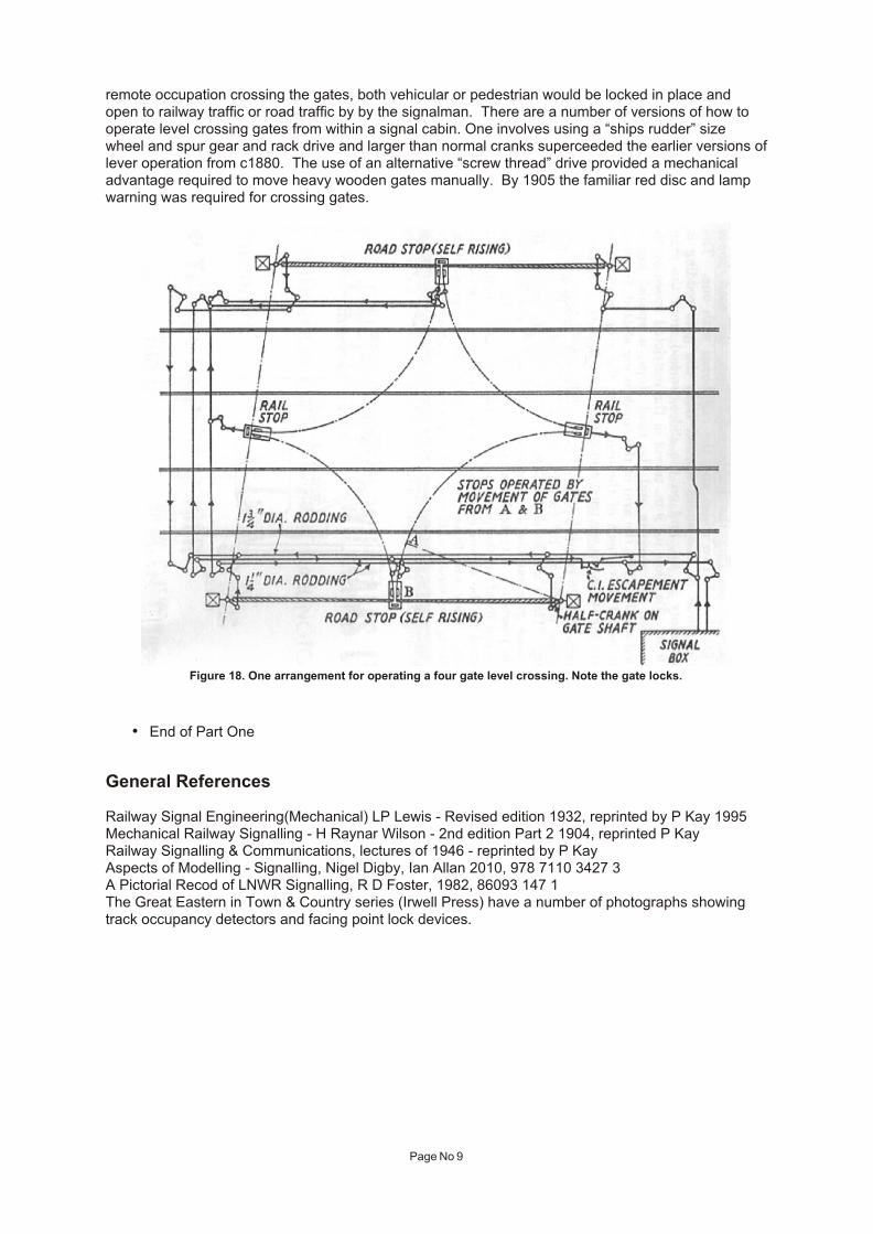
remote occupation crossing the gates, both vehicular or pedestrian would be locked in place andopen to railway traffic or road traffic by by the signalman. There are a number of versions of how tooperate level crossing gates from within a signal cabin. One involves using a “ships rudder” sizewheel and spur gear and rack drive and larger than normal cranks superceeded the earlier versions of lever operation from c1880. The use of an alternative “screw thread” drive provided a mechanicaladvantage required to move heavy wooden gates manually. By 1905 the familiar red disc and lampwarning was required for crossing gates.
• End of Part One
General References
Railway Signal Engineering(Mechanical) LP Lewis - Revised edition 1932, reprinted by P Kay 1995Mechanical Railway Signalling - H Raynar Wilson - 2nd edition Part 2 1904, reprinted P KayRailway Signalling & Communications, lectures of 1946 - reprinted by P KayAspects of Modelling - Signalling, Nigel Digby, Ian Allan 2010, 978 7110 3427 3A Pictorial Recod of LNWR Signalling, R D Foster, 1982, 86093 147 1The Great Eastern in Town & Country series (Irwell Press) have a number of photographs showingtrack occupancy detectors and facing point lock devices.
Page No 9
Figure 18. One arrangement for operating a four gate level crossing. Note the gate locks.