amalgamated nine switch inverter with pv and self ... · pdf filebalance modeling and discrete...
TRANSCRIPT
SSRG International Journal of Electrical and Electronics Engineering - (ICRTESTM) - Special Issue – April 2017
ISSN: 2348 – 8379 www.internationaljournalssrg.org Page 1
Amalgamated Nine Switch Inverter with PV and Self
Supported DVR System
Abstract—This paper proposes a nine switch inverter (NSI) topology amalgamation of photovoltaic (PV) with self-supported dynamic voltage restorer (DVR) with the grid tied system. The proposed system configuration gets rid of the number of switches to less count to nine, which reduce cost and bi-directional power flow in domestic applications while robust against rapid increase sensitive loads. In addition to that mitigate the power quality issues such as voltage sag, swell, balanced/ unbalanced loads and symmetrical/ unsymmetrical faults. Furthermore, reducing the switching losses increases the system efficiency and reliability, a proper discontinuous modulation technique is studied and used. Performance comparison with reduced number of switches, analyses of the proposed inverter by overcoming the compensation of the DVR via simulation results, output waveforms validity under different operating modes.
Keywords—Nine switch inverter topology, solar
power, Maximum Power Point Tracking (MPPT), power
generation, quality power, dynamic voltage restorer.
I. INTRODUCTION
Tremendous usage natural energy resources, overcoming the non-conventional energy resources because of environmental aspects a flexible power generation is obtained by photovoltaic to small and large power generation plants [1]. To obtain a natural green energy source with higher efficiency power through PV generation system of maximum power point control algorithm and the power output through a conversion system is used basically in an
individual voltage source inverter system [2], [3]. In
domestic applications where increase in power electronic loads leads to critical load with major problems with power quality raises affecting the grid voltage by voltage sag, swell, balanced/unbalanced loads and symmetrical/unsymmetrical faults. In distribution system, it becomes more to maintain an uninterruptible power flow to the domestic loads [4], [5].In order to avoid the power quality issues modern custom power (CP) devices fewer than two
groups are a network reconfiguring type and compensating type. The concept of the custom power is tools of application of power electronics controller devices into the power distribution system to supply a
quality of power, demanded by the sensitive users. For the generation of custom power devices voltage source inverter (VSI) is generally used, due to self-supporting of dc bus voltage with a large dc capacitor. In order to compensate the load problems, DVR a high-speed switching device is functional as also named static series compensator. Its applications over voltage regulation, flicker attenuation, voltage sag and swell protection, voltage balancing [6]. In a progress where a grid tied with PV plant with a six switch VSI makes advantages over injecting the active power instead of grid supply to the load terminals [7]. Another problem of sensitive loads makes the system unstable, to rectify that compensation of interrupted voltage during the certain conditions DVR performs it with another six switch VSI. Thus the self-supported DVR will maintain the load voltage to rated power [8]. By the system were a two separate VSI which makes switching losses and increasing the operational time problem cannot be solved [9]. In addition to that proper maintenance over battery is needed. The power rating of the PV depends on the solar panels in array of series and parallel strings towards the inverter output generation [10].
Instead of using the two separate VSI, we move towards nine switch inverter topology make the system dual functionality over various advantages. By using this method, we have reduced switches and computational losses. In addition to that the system with DVR makes more improvement in uninterruptable power supply [11], [12]. The system will make more efficiency over the loads with a quality power to the load centers. In order to achieve a high performance of the compensation takes place for the requirements of the problems in the grid. The proposed work is validated by nine switch inverter
P.DURAI
PG Scholar Department of EEE
Pondicherry Engineering College
Puducherry, India
Dr.P.AJAY-D-VIMAL RAJ
Assistant Professor Department of EEE
Pondicherry Engineering College
Puducherry, India
Dr.M.SUDHAKARAN
Professor Department of EEE
Pondicherry Engineering College
Puducherry, India
SSRG International Journal of Electrical and Electronics Engineering - (ICRTESTM) - Special Issue – April 2017
ISSN: 2348 – 8379 www.internationaljournalssrg.org Page 2
system compensation from sensitive loads over voltage sag by the study over simulation study.
II. PROPOSED SYSTEM
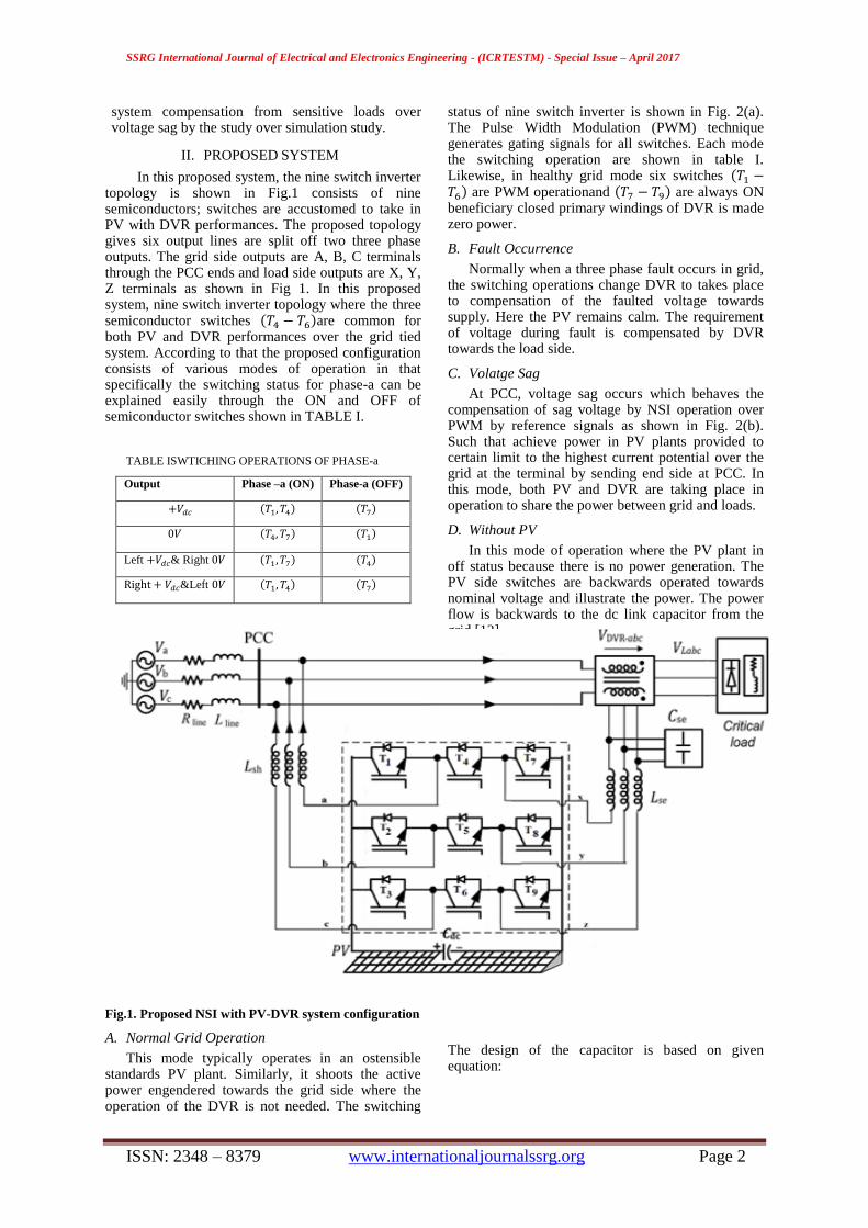
In this proposed system, the nine switch inverter topology is shown in Fig.1 consists of nine semiconductors; switches are accustomed to take in PV with DVR performances. The proposed topology gives six output lines are split off two three phase outputs. The grid side outputs are A, B, C terminals through the PCC ends and load side outputs are X, Y, Z terminals as shown in Fig 1. In this proposed system, nine switch inverter topology where the three semiconductor switches ( )are common for both PV and DVR performances over the grid tied system. According to that the proposed configuration consists of various modes of operation in that specifically the switching status for phase-a can be explained easily through the ON and OFF of semiconductor switches shown in TABLE I.
TABLE ISWTICHING OPERATIONS OF PHASE-a
Output Phase –a (ON) Phase-a (OFF)
( ) ( )
( ) ( )
Left & Right ( ) ( )
&Left ( ) ( )
Fig.1. Proposed NSI with PV-DVR system configuration
A. Normal Grid Operation
This mode typically operates in an ostensible standards PV plant. Similarly, it shoots the active power engendered towards the grid side where the operation of the DVR is not needed. The switching
status of nine switch inverter is shown in Fig. 2(a). The Pulse Width Modulation (PWM) technique generates gating signals for all switches. Each mode the switching operation are shown in table I. Likewise, in healthy grid mode six switches ( ) are PWM operationand ( ) are always ON beneficiary closed primary windings of DVR is made zero power.
B. Fault Occurrence
Normally when a three phase fault occurs in grid, the switching operations change DVR to takes place to compensation of the faulted voltage towards supply. Here the PV remains calm. The requirement of voltage during fault is compensated by DVR towards the load side.
C. Volatge Sag
At PCC, voltage sag occurs which behaves the compensation of sag voltage by NSI operation over PWM by reference signals as shown in Fig. 2(b). Such that achieve power in PV plants provided to certain limit to the highest current potential over the grid at the terminal by sending end side at PCC. In this mode, both PV and DVR are taking place in operation to share the power between grid and loads.
D. Without PV
In this mode of operation where the PV plant in off status because there is no power generation. The PV side switches are backwards operated towards nominal voltage and illustrate the power. The power flow is backwards to the dc link capacitor from the grid [13].
The design of the capacitor is based on given equation:

SSRG International Journal of Electrical and Electronics Engineering - (ICRTESTM) - Special Issue – April 2017
ISSN: 2348 – 8379 www.internationaljournalssrg.org Page 3
[ (
)
] ( )
III. PWM TECHNIQUE The PWM technique over the PV and DVR
switches under the nine switch inverter through reference signals are given below shown in Fig.2.
Fig. 2. PWM through reference signals
( )
( )
( ) (2)
( )
( )
( ) (3)
where and
are the voltage reference
signals. are the modulation ratio, phase
angle and angular frequency (2).It is similar towards the DVR equations for reference signals (3). In order to generate the gate signals as shown in Fig. 3 by using the control blocks for PV and DVR VSIs are obtained.
Fig. 3. Control block for PV and DVR representation
IV. DISTRIBUTION DATA
TABLE IIDISTRIBUTION DATA PARAMETERS
PARAMTERS VALUE
GRID VOLTAGE(rms) 415v
LINE FREQUENCY 50Hz
PV POWER 10KVA
LOAD POWER 10KVA
DC LINK VOLTAGE 700 V
SERIES TRANSFORMER TURN RATIO 1:1
FILTER INDUCTOR AND CAPACITANCE 5mH &50µF
GRID IMPEDANCE 0.5+j0.05Ω
V. MATLAB SIMULINK MODEL
In this section, MATLAB/Simulink-based study is presented to illustrate the feasibility of system configuration. The parameters of simulated system are given in Table II.
A. NORMAL GRID OPERATION (MODE-1)
In this mode simulation results shown in Fig. 4 & 5 the PV is active and DVR is idle. The switches( ) operated through PWM technique and ( ) are HIGH.
Fig. 4. Grid voltage in mode-1
Fig. 5. Real and reactive power in mode-1
B. FAULT OCCURRENCE (MODE-2)
Assume that when a fault occurs in PCC, the nine switch inverter operates towards PV and DVR as shown in Fig. 6. The DVR is taking power to provide the compensation of fault voltage towards the grid at load side as shown Fig. 7.

SSRG International Journal of Electrical and Electronics Engineering - (ICRTESTM) - Special Issue – April 2017
ISSN: 2348 – 8379 www.internationaljournalssrg.org Page 4
Fig. 6. Voltage across grid, DVR, Load in mode-2
Fig. 7. Real and reactive power in mode-2
C. VOLTAGE SAG (MODE-3)
In grid when sag occurs a depth of 50% in sending end voltage as shown in Fig. 8. So that DVR compensation over the presag voltage is supplied to the load side. The power which generated by PV plant is supplied to the load by DVR as shown in Fig. 9.
Fig.8. Voltage across grid, DVR, load in mode-3
Fig. 9. Real and reactive power in mode-3
D. WITHOUT PV (MODE-4)
In proposed configuration when grid without PV supply doesn’t have active power results the total power by DVR. The power required is taken from dc link. This mode corresponds to the intervals when PV plant is not producing any active power. The required load active power is provided by NSI system as shown in Fig 10 & 11.
Fig. 10.Voltage across grid, DVR, load in mode-4
Fig.11. Real and reactive power in mode-4
VI. CONCLUSION
In this paper a nine switch inverter topology amalgamating of PV with a self-supported DVR system is proposed. In this configuration that unveils the utilitarian of surviving system provides power to the load side. It maintains the uninterruptable power supply through DVR compensation when voltage sag,

SSRG International Journal of Electrical and Electronics Engineering - (ICRTESTM) - Special Issue – April 2017
ISSN: 2348 – 8379 www.internationaljournalssrg.org Page 5
fault occurrence and no PV generation are observed through the simulation results. The proposed system configuration has various operations over the grid tied system are enhancing active power by PV and DVR at maximum compensation. It has more advantages over the upcoming load centers.
REFERENCE
[1] T. Esram, J. W. Kimball, P. T. Krein, P. L. Chapman, and
P. Midya, ―Dynamic maximum power point tracking of
photovoltaic arrays using ripple correlation control,‖ IEEE Trans. Power Electron., vol. 21, no. 5, pp. 1282–1291, Sep.
2006.
[2] C. Meza, J. J. Negroni, D. Biel, and F. Guinjoan, ―Energy-balance modeling and discrete control for single-phase
grid-connected PV central inverters,‖ IEEE Trans. Ind.
Electron., vol. 55, no. 7, pp. 2734–2743, Jul.2008.
[3] T. Shimizu, O. Hashimoto, and G. Kimura, ―A novel high-
performance utility-interactive photovoltaic inverter system,‖ IEEE Trans. Power Electron., vol. 18, no. 2, pp.
704–711, Mar. 2003.
[4] L. Zhang, P. C. Loh, and F. Gao, ―An integrated nine-switch power conditioner for power quality enhancement
and voltage sag mitigation,‖ IEEE Trans. Power Electron.,
vol. 27, no. 3, pp. 177–1190, Mar. 2011. [5] Y. Shi, Z. Jun, X. Dou and M. Hu, ―An integrated nine-
switch power conditioner parallel with transformer for
power quality enhancement,‖ IEEE Trans. Power Electron., Mar. 2015.
[6] J. A. Martinez and J. M. Arnedo, ―Voltage sag studies in
distribution networks—Part I: System modeling,‖ IEEE Trans. Power Del., vol. 21, no. 3, pp. 338–345, Jul. 2006.
[7] S. B. Kjaer, J. K. Pedersen, and F. Blaabjerg, ―A review of
single-phase grid-connected inverters for photovoltaic modules,‖ IEEE Trans. Ind. Appl., vol. 41, no. 5, pp. 1292–
1306, Sep./Oct. 2005.
[8] R. A. Walling, R. Saint, R. C. Dugan, J. Burke, and L. A. Kojovic, ―Summary of distributed resources impact on
power delivery systems,‖ IEEE Trans. Power Del., vol. 23,
no. 3, pp. 1636–1644, Jul. 2008. [9] S. S. Choi, J. D. Li, and D. M. Vilathgamuwa, ―A
generalized voltage compensation strategy for mitigating
the impacts of voltage sags/swells,‖IEEE Trans. Power Del., vol. 20, no. 3, pp. 2289–2297, Jul. 2005.
[10] Liu, B. Wu, N. R. Zargari, D. Xu, and J. Wang, ―A novel
three phase three-leg ac/ac converter using nine IGBTs,‖ IEEE Trans. Power Electron., vol. 24, no. 5, pp. 1151–
1160, May 2009.
[11] Y. W. Li, D. M. Vilathgamuwa, F. Blaabjerg, and P. C. Loh, ―A robust control scheme for medium-voltage-level
DVR implementation,‖ IEEE Trans. Ind. Electron., vol. 54,
no. 4, pp. 2249–2261, Aug. 2007. [12] T. Kominami and Y. Fujimoto, ―Inverter with reduced
switching-device count for independent AC motor control,‖
in Proc. 33rd Annu. Conf. IEEE Ind. Electron. Soc. (IECON’07), 2007, pp. 1559–1564 C.
[13]A.M. Rauf and V. Khadikar, ―Integrated photovoltaic and dynamic voltage restorer system configuration,‖ IEEE Trans. Power Electron., vol. 24, no. 5, pp. 1151–1160, May 2015.
P.Durai competed his B.Tech degree in Electrical and Electronics Engineering, from Pondicherry Engineering College in 2015 and is currently pursuing the M.Tech Degree (Electrical Drives and Control) in the Department of Electrical and Electronics Engineering, Pondicherry Engineering College.
Dr.P.Ajay-D-Vimal Raj received the B.E. degree from Madras University in 1998, M.E. degree from Faculty of Engineering, Anamalai University, Tamil Nadu, India, in 1999, and the Ph.D. degree from Pondicherry Engineering College, Pondicherry University, Pondicherry, in 2008. Currently he is Assistant Professor in the Department of Electrical and Electronics Engineering, Pondicherry Engineering College, Pondicherry
University, Pondicherry, India. He is a life member of the Institution of Engineers (India), life member of Indian Society of Technical Education (India), and life member of Society of Power Engineers (India) His research interests include power system control in renewable energy systems and conventional power systems, power system optimization, analysis of power quality issues, and application of artificial intelligence techniques in power systems.
Dr.M.Sudhakaran received the B.E. degree from ManonmaniamSundaranar University, Tirunelveli in 1997, M.E.
degree from Thiagarajar College of Engineering in 1999 and the Ph.D. degree from Thiagarajar College of Engineering, in 2004.
Currently he is Professor in the Department of Electrical and
Electronics Engineering, Pondicherry Engineering College, Pondicherry university, Pondicherry, India. He is a life member of
the Institution of Engineers(India),life member of Indian Society
for Technical Education (ISTE), andReviewer of National/International Journals. His area of research includes
Power System Operation and Control, Reactive Power
Management, Application of FACTS controllers, Soft computing techniques for Power system optimization, Power system
restructuring and deregulation.