aluminum tooling via composite manufacturing - sites.udel.edu
TRANSCRIPT

© 2010 University of Delaware, All rights reserved
Aluminum Tooling Via Composite Manufacturing
Zach Melrose, Tom Mulrooney, Kyle Steelman, Brian Traylor
Department of Mechanical Engineering &
Center for Composite Materials
Trabant MPR B 12/13/2010
Senior Design

© 2010 University of Delaware, All rights reserved
Project Description
Alcore is one of the world’s leaders in providing lightweight structural honeycomb materials for use in many industries.
Alcore utilizes aluminum tool to cut the honeycomb structures to their precise geometry.
Our project is to create an efficient process to convert one of Alcore’s current aluminum tools into a composite tool.
Our project revolves around researching and developing this process for Alcore.
5 axis mill
cutting head
Aluminum Tool
© 2010 University of Delaware, All rights reserved
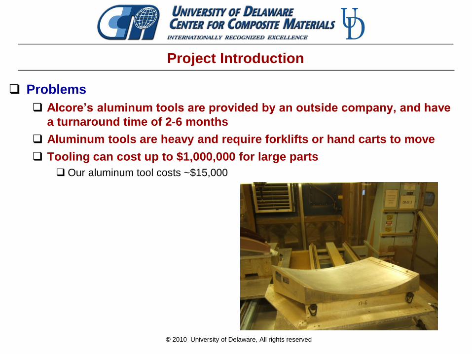
Project Introduction
Problems
Alcore’s aluminum tools are provided by an outside company, and have
a turnaround time of 2-6 months
Aluminum tools are heavy and require forklifts or hand carts to move
Tooling can cost up to $1,000,000 for large parts
Our aluminum tool costs ~$15,000

© 2010 University of Delaware, All rights reserved
Project Introduction
Solution
Replace aluminum tools with equally functioning composite tools
Goals
Allow Alcore to make new tools in house
Reduce cost of tooling
Reduce turnaround time of tools

© 2010 University of Delaware, All rights reserved
Steps
1. Using an existing aluminum tool as a mold, copy the surface
using carbon fiber composites and the VARTM process
• Verify materials
• Observe dimensional stability
2. Thermally cycle tool to test part stability
3. Perfect dimensional stability and infusion of parts
4. Find an inexpensive, machinable material (e.g. foam) to create
new tool molds
5. Use these molds to form carbon fiber tools
Project Introduction
© 2010 University of Delaware, All rights reserved
Needs and Wants
Needs
Reusable- ~ 1000 uses
Versatile- Adaptable to different part geometries
Thermal Stability- Withstand temperatures up to 350oF
Wants
Cost- Affordability of the system
Light Weight- Ease of use for one operator
Simplicity- Mold making process
Compatibility- With supporting structure
Dimensional stability- 1/100 inch
Durability- Resistant to damage

© 2010 University of Delaware, All rights reserved
Constraints
Frame
Compatibility with current CNC operation
Tooling Surface
Impermeable to cleaning fluids and release agents.
Tooling Surface
Frame

© 2010 University of Delaware, All rights reserved
Project Overview
Composite Tool Materials
VARTM process
LIMS Analysis
Composite Tool Assembly
Concept Validation
Results
Future Development
© 2010 University of Delaware, All rights reserved
Materials
Resin System
Toolfusion 3A/3B: Airtech Advanced Materials
Substance that is infused into the fiber to create the composite
tool.
Fiber
3K count 4-Harness satin weave carbon fiber
produced by Hexcel

© 2010 University of Delaware, All rights reserved
Materials
Gel Coat
Infusion Coat 1A/1B by Airtech
Increases Hardness
Increases Thermal Conductivity
Creates a smooth and glossy finish to the composite tool.
Release Agent
Frekote produced by Henkel
Reduces fracturing and deformation when the composite tool
is separated from the aluminum tool.

© 2010 University of Delaware, All rights reserved
Vacuum Assisted Resin Transfer Molding
Carbon Fiber Preform

© 2010 University of Delaware, All rights reserved
Vacuum Assisted Resin Transfer Molding
Resin Front
Resin Inlet
Vacuum
Outlet
Tacky
Tape Seal

© 2010 University of Delaware, All rights reserved
VARTM of Negative Tooling Surface
© 2010 University of Delaware, All rights reserved
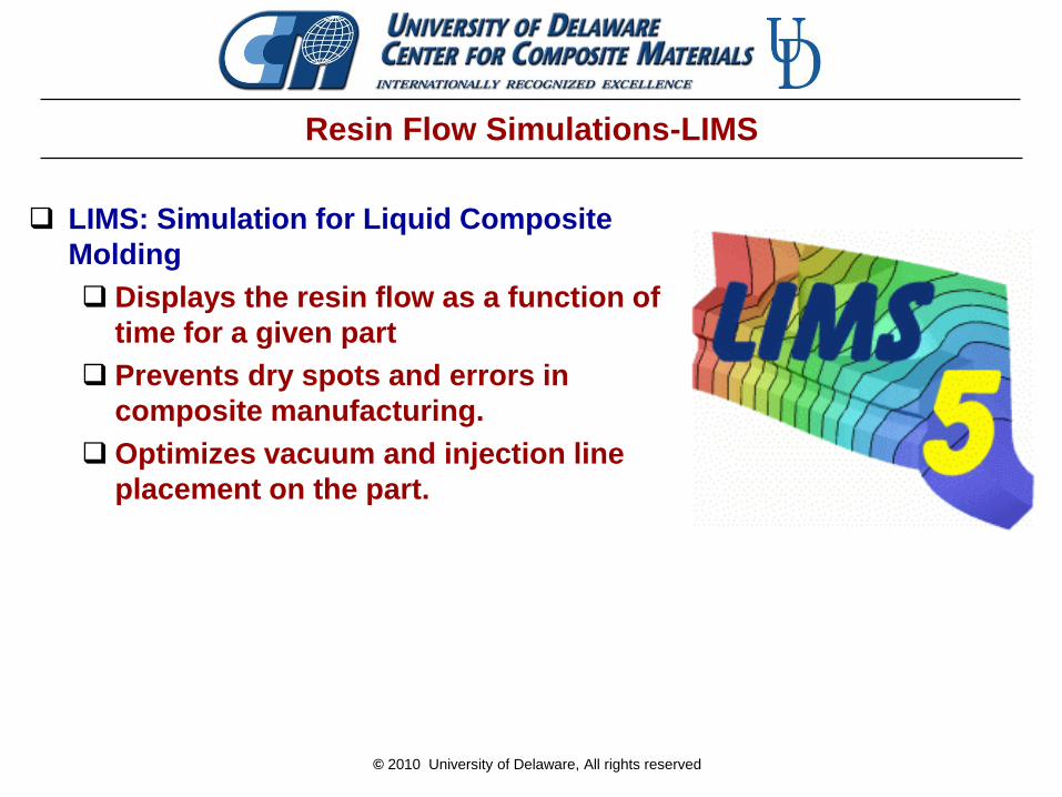
Resin Flow Simulations-LIMS
LIMS: Simulation for Liquid Composite
Molding
Displays the resin flow as a function of
time for a given part
Prevents dry spots and errors in
composite manufacturing.
Optimizes vacuum and injection line
placement on the part.

© 2010 University of Delaware, All rights reserved
LIMS: Required Properties
Permeability, k
Measureable through an experimental procedure
Unique to each type of fabric.
Injection Pressure, Pa
Vacuum pressure that pulls the resin across the part
Known value from laboratory vacuum pump
Resin Viscosity, cps
Measure of the resistance of the resin when flowing
Measured value based on ambient air temperature
Fiber volume fraction, Vf
Measure of the amount of fiber present in cured composite
Assumed value is 50%
Thickness, cm
Overall thickness of the fabric layers
© 2010 University of Delaware, All rights reserved
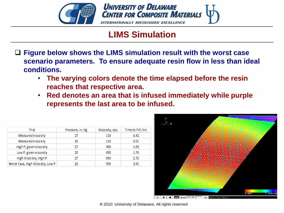
LIMS Simulation
Figure below shows the LIMS simulation result with the worst case
scenario parameters. To ensure adequate resin flow in less than ideal
conditions.
• The varying colors denote the time elapsed before the resin
reaches that respective area.
• Red denotes an area that is infused immediately while purple
represents the last area to be infused.
© 2010 University of Delaware, All rights reserved
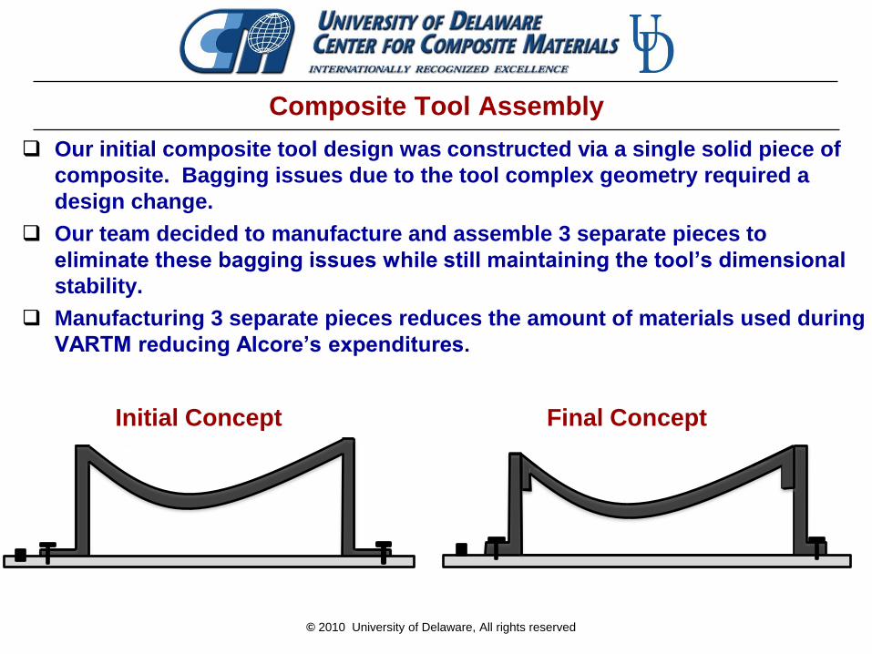
Composite Tool Assembly
Our initial composite tool design was constructed via a single solid piece of
composite. Bagging issues due to the tool complex geometry required a
design change.
Our team decided to manufacture and assemble 3 separate pieces to
eliminate these bagging issues while still maintaining the tool’s dimensional
stability.
Manufacturing 3 separate pieces reduces the amount of materials used during
VARTM reducing Alcore’s expenditures.
Initial Concept Final Concept
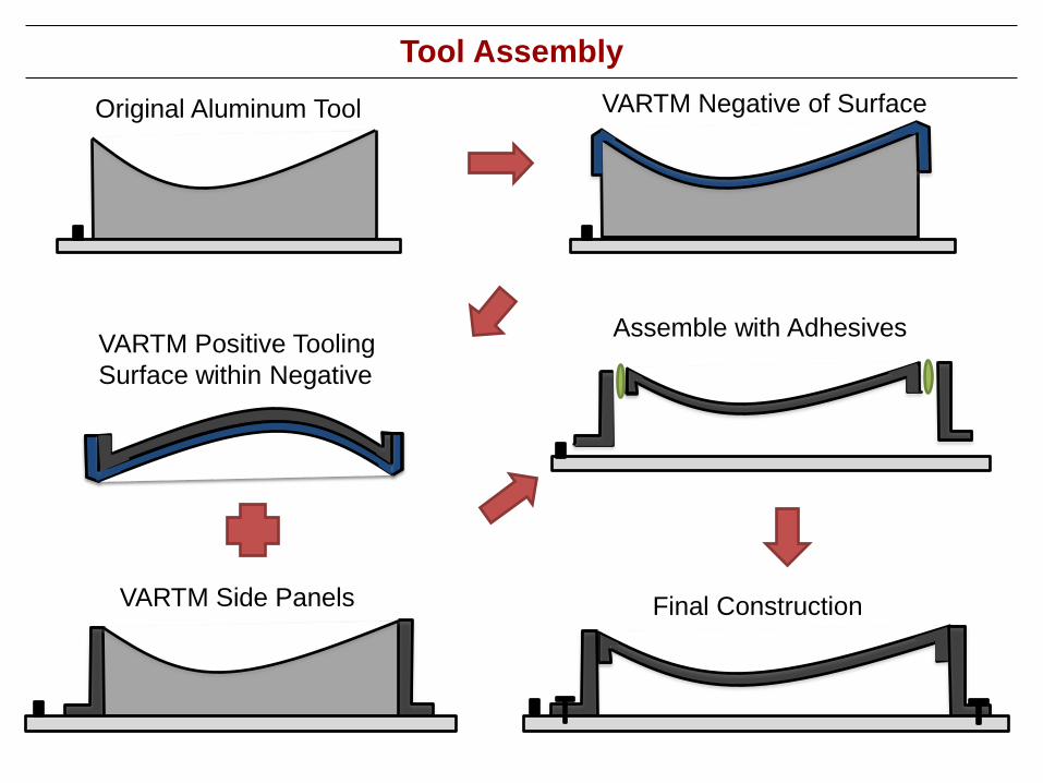
VARTM Side Panels
VARTM Positive Tooling
Surface within Negative
Original Aluminum Tool
Tool Assembly
VARTM Negative of Surface
Assemble with Adhesives
Final Construction

© 2010 University of Delaware, All rights reserved
Results
Verified composite manufacturing
process.
Produced a composite negative
to form the final composite tool.
Produced composite tool replica
based on the original aluminum
tool.
Successfully used materials with
high service temperatures to
produce the composite tool.
Composite tool surface is
impermeable to cleaning fluids.

© 2010 University of Delaware, All rights reserved
Metrics & Target Values
Reduce weight so tool requires one operator to maneuver.
• Weight of Aluminum Tool : 310 lbs.
• Weight of Our Composite Assembly : 6.5 pounds
Rapid Manufacturing of new Tools.
• Aluminum tool Lead time: 2 months
• Our Composite Assembly: 6 days
Low viscosity resins to apply VARTM to large parts.
• Sponsor wanted viscosity < 250 cps.
• Measured Toolfusion 3 viscosity: 110 cps.

© 2010 University of Delaware, All rights reserved
Concept Validation
Ensure the dimensions of the composite tool match the
dimensions of the original aluminum tool. Use a high precision optical scanner to measure dimensional
stability
To test the deflection of the tool under load, the tool will be
subjected to elastic deformations up to the tolerance limit to
determine the maximum load.
Validate our process by thermal cycling our composite tool to
measure thermal fatigue.

© 2010 University of Delaware, All rights reserved
Future Development
Alcore will thermal cycle the composite tool our team produced
to ensure its durability and endurance.
Dimensional stability of the composite tool will be validated
through optical scanning and force tests.
If the tool is passes the thermal testing, Alcore will proceed to
develop processes and procedures to employ composite tooling.
Alcore will determine the most efficient and beneficial methods
of utilizing composite manufacturing to replace their aluminum
tool stock.
© 2010 University of Delaware, All rights reserved
Acknowledgements
Special Thanks:
Alcore Mr. Eric Franzoi
Center for Composite Materials Phil Roach, Hope Deffor, Ray McCauley
Department of Mechanical Engineering Dr. James Glancey, Steve Beard, Dr. Erik Thostenson
University of Delaware

© 2010 University of Delaware, All rights reserved
Questions
Questions
Comments
&