aluminum alloys and behavior under cyclic loading in...
TRANSCRIPT

http://www.iaeme.com/IJCIET/index.asp 746 [email protected]
International Journal of Civil Engineering and Technology (IJCIET) Volume 8, Issue 11, November 2017, pp. 746–752, Article ID: IJCIET_08_11_076
Available online at http://http://www.iaeme.com/ijciet/issues.asp?JType=IJCIET&VType=8&IType=11
ISSN Print: 0976-6308 and ISSN Online: 0976-6316
© IAEME Publication Scopus Indexed
ALUMINUM ALLOYS AND BEHAVIOR UNDER
CYCLIC LOADING IN JOINTS OF TRUSS
STRUCTURES
Ragip Hadri
Department of Civil Engineering, University of Prishtina, Bregu I Diellit P.N,Prishtine
Ali Muriqi*
Department of Civil Engineering, University of Prishtina, Bregu I Diellit P.N,Prishtine
*Corresponding author
ABSTRACT
Aluminum is the second most widely specified metal in building after steel, and is
used in all sectors from commercial building to domestic dwelling. This paper
contains overview of use of aluminum in building construction, specifically in
connections of trust elements. This paper also contains the properties of aluminum
alloys, setup of testing, advantages and no advantages under the cyclic loads. The
used properties parameters during the testing are compared with the parameters
given by the manufacturer, the standards of the European Aluminum Association and
Eurocode 9. Testing of the models was performed on a hydraulic press (pulsator),
Amsler''.The behaviour of join was focused in long period during the testing to
analyze the failure mode and to compare with dynamic factor using in analytical
method using during the experiment.
This concept was reasonly accepted such dynamic coefficient in the diagonal D1,
such trust element in value γD = 1,6. European Aluminium Association still doing
research on getting the dynamic coefficients of fatigue for aluminum alloys and this
research will present the contribution in this regard.
Keywords: Aluminum Alloys, Connections, Testing, Cyclic loads, Failure
Cite this Article: Ragip Hadri and Ali Muriqi, Aluminum Alloys and Behavior under
Cyclic Loading in Joints of Truss Structures, International Journal of Civil
Engineering and Technology, 8(11), 2017, pp. 746–752
http://www.iaeme.com/IJCIET/issues.asp?JType=IJCIET&VType=8&IType=11
1. INTRODUCTION
The increasing use of engineering materials in different types of loading requires that the
materials have good mechanical properties in these conditions. Fatigue is one of the principle
damage mechanisms or materials operating under loading conditions. During the cyclic
Ragip Hadri and Ali Muriqi
http://www.iaeme.com/IJCIET/index.asp 747 [email protected]
loading process the behavior of the structure will be under larger strain deformation, crack
initiation and growth. Finally the material or structure may fail in different modes, fatigue,
rupture, large deformation, or brittle failure of the materials in connection or joints of
structure.[1].
The fundamental principles of behavior during the analytical and testing are same such in
steel constructions:
• Chemical analysis of aluminum alloy
• Mechanical properties of materials, in our case , testing the tensile strength
• Mode of failure during the testing
• Testing set up
• Apply the cyclic loads
For different elements of trust structure during the research are analyzing the three
aluminum alloys: EN AW 6063 T66; EN AW 6028 T656; EN AW 6028 T6. For all types of
materials are make the analysis before the trust is designed.
The focused point was in joints and effects of bolts in this positions using the opening for
connections and the compatibility between the materials and bolts.[1,2,3].
2. MATERIALS AND EXPERIMENTAL PROCEDURES
The tested materials were aluminum alloys, namely the AW 6063 T66; AW 6028 T656 and
AW 6028 T6 alloys. The chemical composition is shown in “Table 1”; Metallographic
Analyses presented in “Fig. 1” has been examined in and their mechanical properties are
presented in “Table 2”. An axial tensile test has been made using 3 samples for each alloy,
and they were prepared according ASTM E660 “Fig. 2”.Tensile tests were performed on
tensile test machine to obtain monotonic stress.[9,10,11].
Table 1 Chemical analysis of aluminum alloys
Symbol of elements
and alloy Si% Fe% Cu% Mn% Mg% Zn% Ag% Bi% Cd%
Profile L50x5
EN AW 6063 T66 0,49 0,21 0,084 0,04 0,49 0,030 0,510 0,0003 0,007
Plate thicknees-6mm
EN AW 6028 T651 0,89 0,20 0,095 0,35 0,91 0,038 0,503 0,0003 0,007
Joint elements –Bolts
EN AW 6028 T6 0,83 0,18 0,210 0,40 0,65 0,020 0,510 0,0002 0,007
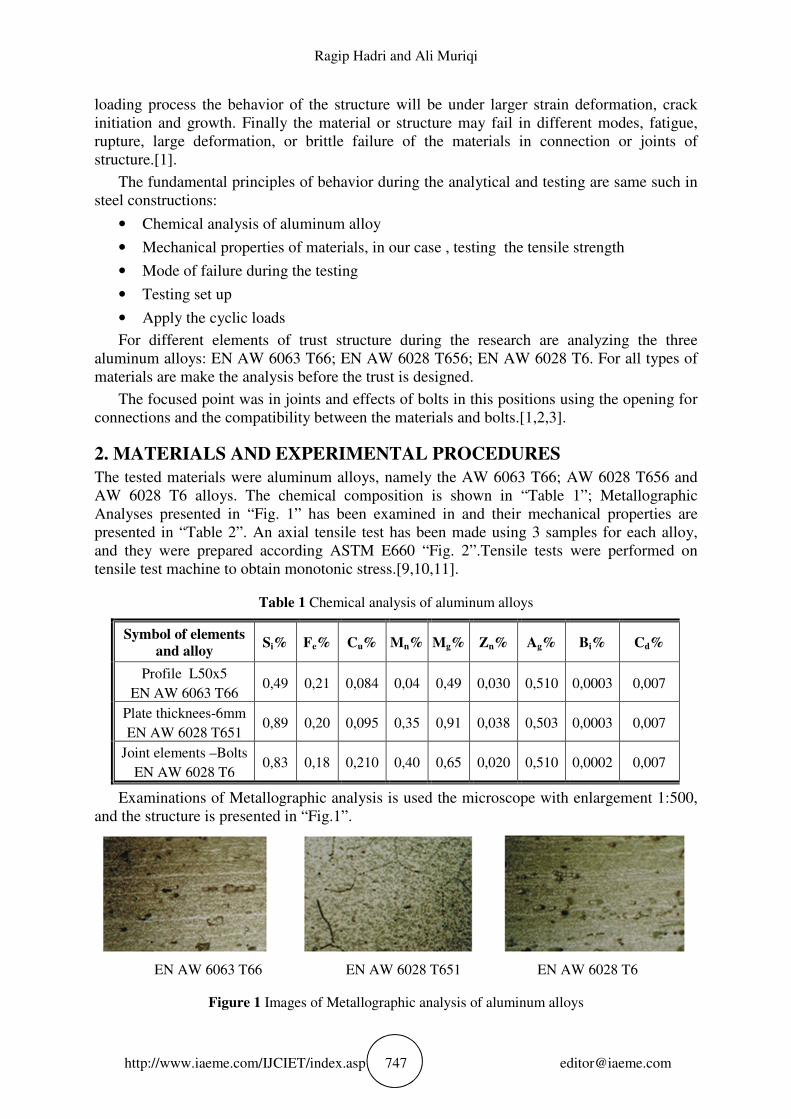
Examinations of Metallographic analysis is used the microscope with enlargement 1:500,
and the structure is presented in “Fig.1”.
EN AW 6063 T66 EN AW 6028 T651 EN AW 6028 T6
Figure 1 Images of Metallographic analysis of aluminum alloys

Aluminum Alloys and Behavior under Cyclic Loading in Joints of Truss Structures
http://www.iaeme.com/IJCIET/index.asp 748 [email protected]
The mechanical properties are done in prepared samples examined in standard process
according the ASTM E660 using the type of equipment “Amsler”, and the failure of samples
for three types of aluminum alloys is presented in “Fig.2”.
Figure 2 Failure of different types of examined aluminum alloys
Behaviour of materials-aluminum alloys under applied the loads and deformations is
presented through the chart “σ-ε” , in fig. 3, and Modulus of Elasticity , presented in “table 2”.
Figure 3- Behaviour the three types of aluminum alloys under load apply
Table 2-Modulus of Elasticity of Aluminum Alloys for Profiles and plates
Sign ∆����� ∆�� ∙ �� ����� �����
�� ������
L-profiles 50х50х5mm
1 1 1,460 1,030 66500
2 1 1,490 1,020 65800
3 1 1,495 1,025 65260
Average 66250
Aluminium plate �~���
1 1 1,232 1,162 69850
2 1 1,236 1,170 69150
3 / / 1,200 58724
Average 65820

Ragip Hadri and Ali Muriqi
http://www.iaeme.com/IJCIET/index.asp 749 [email protected]
3. TEST SETUP
The program for experimental examinations is focused on the truss structures with aluminum
alloys, were the elements of trust are prepared with the aluminum alloys EN AW 6063 T66 ;
the aluminum plates with EN AW 6028 T651 and bolts with aluminum alloys type EN AW
6028 T6. The construction of structure is design and the structural elements are presented in
“fig.4”, with geometrical parameters and “fig.5”.[10],[5],[6].
Figure 4 Geometrical parameters of truss structure
Figure 5 Truss Structure prepared for testing
In middle span of truss structure; point 1 is fixed the pulsator for applied the cycling load
and in strain gauges are fixed in each point of structure to analyze the deformations under
cyclic vertical loads. The typical used strain gauges are with following parameters:
• Factor K=2.06 ±1.0 %
• Resistance R=120 Ω±0.35 %
• Accuracy T=0.1 %
The conditions during the setup during the all-time of examinations are laboratory
conditions with no changes. The strain Guages are connection in data logger were results are
read during the experiment.[10],[11],[4],[6].
The schematic measurements are done according to the “fig.6”, were all parameters
necessary for analyses and behavior.
Aluminum Alloys and Behavior under Cyclic Loading in Joints of Truss Structures
http://www.iaeme.com/IJCIET/index.asp 750 [email protected]
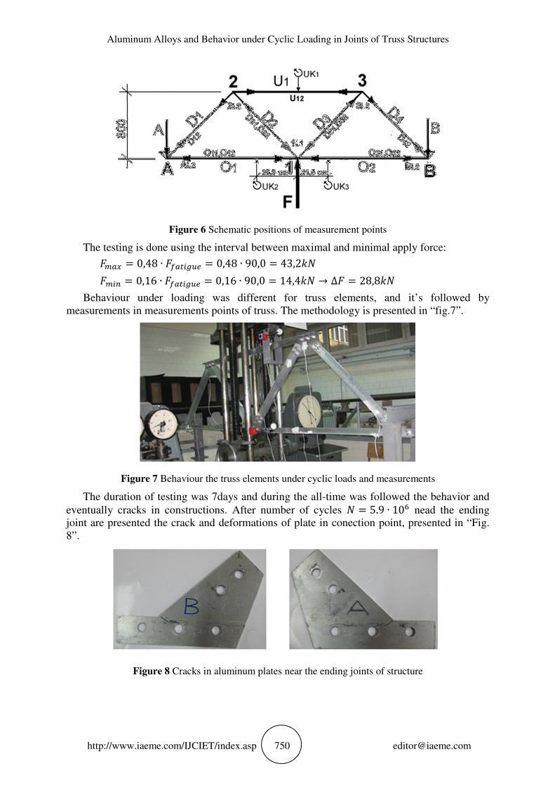
Figure 6 Schematic positions of measurement points
The testing is done using the interval between maximal and minimal apply force:
���� 0,48 ∙ �%�&'()* 0,48 ∙ 90,0 43,2./
��'0 0,16 ∙ �%�&'()* 0,16 ∙ 90,0 14,4./ → ∆� 28,8./
Behaviour under loading was different for truss elements, and it’s followed by
measurements in measurements points of truss. The methodology is presented in “fig.7”.
Figure 7 Behaviour the truss elements under cyclic loads and measurements
The duration of testing was 7days and during the all-time was followed the behavior and
eventually cracks in constructions. After number of cycles / 5.9 ∙ 106 nead the ending
joint are presented the crack and deformations of plate in conection point, presented in “Fig.
8”.
Figure 8 Cracks in aluminum plates near the ending joints of structure

Ragip Hadri and Ali Muriqi
http://www.iaeme.com/IJCIET/index.asp 751 [email protected]
4. RESULTS AND DISCUSSION
Based on the results and behavior the structural element under cyclic loads: ∆� 28,8./
and the numer of cycles / 5.9 ∙ 106 too large cracks are evidently comapring with number
of cycles according to the EC 9, were the limit of cycles was limited in /7 5 ∙ 106. In
relations with nuber of cycles in “fig.9” is presented the decrease of the bearing capacity and
evidence of the fatigu of the materials.[10].
Figure 9 The behavior of the aluminum material under critical cycling load
5. CONCLUSIONS
The analyzis in model under the cyclic loadings was done according to the EC 9 and BS 8118
we can conclude:
• Compare the analytical results calculated by program STAD and experimental
examinations the results are different, because the aluminum alloys under cyclic loads
are more sensitive than analytical calculation process.
• The dynamic coefficient 89 1,6under cyclic load is more less than predicted value
under the force coefficient: 8: 2,5
• The value of parcial coeficient in fatigue effect is one of the parameter for detail
analysis ans approval such natioanal parameter.
• The result of dynamic coefficient is very imortant if we use in bridge constructions
under cyclic loads were the fatigue of materials is one of the important factor.
REFERENCES
[1] J.Dwight; Aluminum Design and Construction, 1999, Amazon, London, New York
[2] P.Makelanien &P.Hassinen; Light Weight steel and aluminum Structures, 1999, Esevier,
Amsterdam.
[3] Spon P.S.Bulson; Aluminum Structural Analysis, 1992,Elsevier, New York
[4] Randolph Kissel, Robert Ferry; Aluminum Structures, 1995,Amazon, Canada

Aluminum Alloys and Behavior under Cyclic Loading in Joints of Truss Structures
http://www.iaeme.com/IJCIET/index.asp 752 [email protected]
[5] Wilquin H; Aluminum Architecture-Constructions and Details,2001,Birkhauser, Basel,
Boston
[6] Federico M.Mazzolani; Aluminum Alloy Structures, 2002;Taylor&Francis, London.
[7] George Totem&Scot Meckenzie; Handbook of Aluminum, Volume I, 2003, CRC,USA
[8] Eurocode 9; Design of aluminum structures; part 1-1, 2007
[9] Vikas Piprani&Frchi Samal; Fatigue life estimation of per-corroded aluminum alloys
specimen,Rourcela,2005
[10] R.Hadri; The application of analytical and experimental methods for testing static and
dynamic capacity of the connections in structures of aluminum alloys, 2014,PhD Thesis,
Skopje,
[11] Azim Oshkour; Fatigue Crack propagation in aluminum alloys 60663 tubes, 2009,
Malaysia
[12] Sudip Chapagai and G. Premkumar Experimental study on size effect of R.C. Beam-
column joint with and without hybrid fibres under cyclic loading International Journal of
Civil Engineering and Technology, 8(4), 2017, pp.2198-2209
[13] Mustafa A. Rijab and Ali I. Al-Mosawi, Improve Microstructure of Aluminum Alloys by
Modification, International Journal of Advanced Research in Engineering and Technology
(IJARET) ISSN 0976 - 6480 (Print) ISSN 0976 - 6499 (Online) Volume 5, Issue 6, June
(2014), pp. 62-67
[14] Sabitha Jannet and R. Raja, Microstructure Analysis of Friction Stir Welded AA 5083 and
AA6061 T6 Aluminum Alloys, International Journal of Mechanical Engineering and
Technology (IJMET), Volume 8, Issue 7, 8(7), 2017, pp. 328-333
[15] Abdul Khaliq A. Hasan, Tap Water Effect on Some of Mechanical Properties of
Aluminum Alloys, International Journal of Mechanical Engineering and Technology
(IJMET) Volume 8, Issue 3, March 2017, pp.365-372.