alternative solutions for fronthauling based on dsp
TRANSCRIPT

1
Alternative Solutions for
Fronthauling based on DSP-assisted
Radio-over-Fiber
P. Torres-Ferrera1, S. Straullu2, S. Abrate2 and R. Gaudino3 1 Institute of Engineering, Universidad Nacional Autónoma de México, UNAM, 04510 Mexico City - Mexico, [email protected]
2ISMB, Istituto Superiore Mario Boella, Via P.C. Boggio 61, Torino (TO), Italy, [email protected]
3 Politecnico di Torino, C.so Duca degli Abruzzi 24, 10129 Torino (TO), Italy, [email protected]
OPTCOM - Dipartimento di ElettronicaPolitecnico di Torino – Torino – Italy
www.optcom.polito.it
A short introduction on Fronthauling for CRAN
Mainstream architectures:
CPRI
Alternative architectures
DSP-Assisted analog Radio over Fiber (RoF)
Our recent results on the optimization of DSP-Assisted
RoF Fronthauling Solutions
Presentation outline for Invited Paper
2
This work was partially sponsored by CISCO in the
framework of RFP 2015 «5G–PON»
We also would like to thank Tektronix for
lending us the instruments

2
The Fronthauling architecture
3
Baseband units
(BBU) pools at
Central Office
Transport of “native
radio waveforms”
over fiber (RoF)
Simple interface at
antenna site (RRH:
Remote Radio Head)
Fronthauling using Digitized Radio over Fiber
Antenna
I/Q modulator
Very thin framing protocol (such as CPRI)
I Q
DAC DAC
I/Q demod
I Q
ADC ADC
Central
office
Optical fiber link
(usually P2P but it can also be PON)
CPRI transceiver
Physical Layer DSP
Network layer interfaceBit rate in the Gbps range
at this interface
RF localoscillators
Baseband Unit (BBU)
This approach is sometimes indicated as Digitized Radio-over-Fiber (DRoF)
CPRICommon Public
Radio Interface
Remote Radio Head (RRH)

3
Digitizing one 20-MHz LTE channel
To “digitize” a 20-MHz LTE-A radio signal one needs:
Two I/Q DACs
Each of the them runs at 30.72 Msamples/s
The number of bits per sample is 15 (or higher)
The OFDM signal in radio should be generated in an “almost perfect” way, there is no possibility for clipping, since it would distort the radio spectrum, generating unwanted spurious radio frequencies
The resulting bit rate to be carried using a “digitized” approach is thus:
30.72 Msamples/s x 2 x 15 = 921.6 Mbit/s
CPRI adds some control words (overhead 16/15) and a line code (8B/10B) thus generating in the end a bit rate for each 20 MHz LTE channel equal to 1.23 Gbit/s
5
An “advanced” future antenna site
In a near future, each antenna site may :
More than 3 “angular” sectors
Today typically there are 3 sectors at 120 degrees each)
More than one 20 MHz band on each sector
NxM MIMO
Assuming (just as an “advanced” example):
six sectors
three 20 MHz bands
8x8 MIMO
one gets 144 “bands”, giving rise using CPRI to an enormous bit rate per antenna site equal to
177 Gbit/s
6

4
AN ALTERNATIVE
APPROACH:
DSP-AGGREGATED
FDMA-BASED
FRONTHAULING
7
Aggregation by Frequency Division Multiplexing
8
Frequency up-conversion
around f1
Frequency up-conversion
around fN
Frequency up-
conversion
around f2Electrical
FDM aggregated signal
f
GFDM( f )
…
f1 f2 fN
f
G1( f )Spectrum for LTE
signal
(complex envelope )
#1
f
GN( f )Spectrum for LTE signal
(complex envelope )
#N
… f
G1( f )Spectrum for LTE
signal
(complex envelope )
#2
Baseband complex
signals to be
delivered to the RRH

5
Basically… an updated version of Radio over Fiber (RoF)
9
Electrical FDM aggregated signal
f
GFDM( f )
…
f1 f2 fN
)(tI inElectrical domain
Directly Modulated
Laser Optical Fiber
PIN/APDphotodiode
)(tIout
Radio over Fiber link
FDM De-aggregation
f
G1( f )Spectrum for LTE
signal
(complex envelope )
#1
f
GN( f )Spectrum for LTE signal
(complex envelope )
#N
Electrical domain
The FDM aggregation can
be in principle obtained
by using hardware radio-
frequency (RF) electrical
I/Q modulators
Anyway, if the target is
aggregating tens of
signal, the resulting
electronic would be too
expensive
How to perform aggregation?
10
f
G1( f )Spectrum for LTE
signal
(complex envelope )
#1
f
GN( f )Spectrum for LTE signal
(complex envelope )
#N
…
Frequency up-conversion
around f1
Frequency up-conversion
around fN
f
G1( f )Spectrum for LTE
signal
(complex envelope )
#2
Frequency up-conversion
around f2Electrical
FDM aggregated signal
f
GFDM( f )
…
f1 f2 fN
Equivalent implementation by
Digital Signal Processing (DSP)

6
DSP-aggregated Fronthauling
11
Each of these
“slices” is a LTE 20 MHz
OFDM signal
ECOC 2015
The DSP-aggregation principle
12
Digitized Time-Domain complex envelopes for K LTE signals
][~ ixK][~1 ix ][~
2 ix
N=16 points FFT
N=16 points FFT
N=16 points FFT
][~
1 iX ][~
2 iX ][~
iX K
vector
2 NKM
1f 2f kf
][~
1 iX ][~
2 iX ][~
iX K
IFFT 2 NKM
][ixFDM
Time domain
Frequency domain
Time domain
Complex conjugates

7
In the original Huawei ECOC2015 experiment, 48 LTE
signals were carried over approx. 1.5 GHz of electrical
analog bandwidth
The CPRI approach would have required
approximately 48x1.23Gbit/s ≈ 60 Gbit/s
This is the clear advantage of the new proposal
Comparison of CPRI and G.RoF
13
≈1.5 GHz
OUR EXPERIMENTS ON
DSP-AGGREGATED FDMA FRONTHAULING
OPTIMIZATION OF THE
SYSTEM PARAMETERS
8
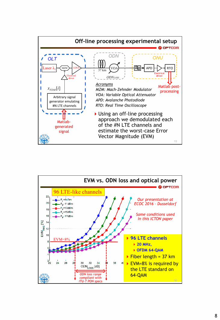
Using an off-line processing approach we demodulated each of the #N LTE channels and estimate the worst-case Error Vector Magnitude (EVM)
Off-line processing experimental setup
15
ONU
APD
ODN
37 km
ODNLOSS
VOA
OLT
EDFA MZM RTO
Arbitrary signalgenerator emulating
#N LTE channels
ElectricaldriverElectrical
driver
Laser λ1
Acronyms
MZM: Mach-Zehnder Modulator
VOA: Variable Optical Attenuator
APD: Avalanche Photodiode
RTO: Real Time Oscilloscope
][ixFDM
Matlab-
generated
signal
Matlab post-
processing
EVM vs. ODN loss and optical power
96 LTE channels
20 MHz,
OFDM 64-QAM
Fiber length = 37 km
EVM=8% is required by
the LTE standard on
64-QAM
Our presentation atECOC 2016 – Dusseldorf
Same conditions usedin this ICTON paper
16
96 LTE-like channels
EVM=8%
ODN loss rangecompliant with ITU-T PON specs

9
In order to obtain the result presented at ECOC 2016
we had to optimize several system parameters, and
in particular:
1. Clipping factor to reduce signal Peak-to-Average-
Power Ratio (PAPR)
2. Simple nonlinearity compensation
3. Channels power equalization
Our ICTON paper is focused on these optimizations
Which were not presented at ECOC 2016
Parameters to be optimized
17
The resulting DSP-aggregated signal
has an amplitude distribution that is
very close to a Gaussian probability
density function
Being the sum of many (such as 96)
OFDM channels
That are already Gaussian-shaped
We define here the clipping factor as:
Where:
ss is the standard deviation of the
DSP-aggregated Gaussian-like signal
Vpp is the peak to peak amplitude of
the signal AFTER clipping
How to properly clip the signal
18
ppV
The clipping factor
was the first
parameter we
optimized

10
The link we used, being based on Mach-Zehnder modulator (MZM) and direct-detection, was intrinsically (mildly) nonlinear, due to the cos2(∙)instantaneous response of the MZM
We want to introduce a correction of the nonlinearity in the DSP domain
But we want to keep it simple, avoiding Volterra’s series approach
We found that a simple cubic relation in DSP can highly reduce the impact of nonlinearities
How to compensate for the link nonlinearity
19
3xCFxxcorr
The nonlinear CF
factor was the second
parameter we
optimized
Clipping and nonlinearity compensation: WHERE?
20
ONU
APD
ODN
37 km
ODNLOSS
VOA
OLT
EDFA MZM
x
RTO
Arbitrary signalgenerator emulating
#N LTE channels
ElectricaldriverElectrical
driver
Laser λ1
][ixFDM
Matlab-
generated
signal
Matlab post-
processing
We experimentally
investigated on where to
apply the correction
factors: transmitter or
receiver side?

11
Conclusion: the compensation at the RX gave better results, and we thus performed all our further experiments in this condition
CLIPPING and nonlinearity comp at TX or RX?
21
Transmitter side Receiver side
(with 12 dB clipping also at TX)
Error Vector Magnitude (EVM) on the output channels
Optimized EVM vs. Optical Path Loss
22
96 LTE channels,
20 MHz, OFDM 64-QAM
Fiber length = 37 km
+9dBm optical launched
power
Conclusion: optimization can be done at a given (reasonable) optical path loss, and then kept for all other operating conditions

12
Particularly for the high number of channels, the aggregated FDM signal can occupy a large bandwidth, over which the direct-detection channel is not flat in terms of:
Frequency transfer function
Receiver noise power spectral density
The resulting SNR (and thus EVM) per channel can be significantly different
Compensation of frequency dependence
23
29 dB
27 dB
optical path loss
EVM=8%
acceptable threshold
Channel #92 is
around 3.2 GHz
We need to perform a power equalization at the transmitter
… and again, keep it simple!
We simply insert a multiplication with some proper multiplying ki
coefficients in the TX DSP aggregator block diagram
The coefficient were evaluated using a min-max algorithm
Minimization of the worst-case EVMi among all received channels
Proposed approach: DSP-based pre-emphasis
24
DAC
,FDM mx ( )FDMx t
1 ,1mk s
,ch chN m Nk s
.
.
. FDM DSP
Aggregator
,1ms
, chm Ns
.
.
.
X
1k
X
chNk
. . .
Pre-emphasis
Nch OFDM
Complex
Baseband
generator
,
target
EVM
EVM
out no pre
ii out
k
2,
2
target
1 1 target
1 1 EVM(EVM ) 1
EVM
ch chN N out no preout i
DS i outi ich ch
G kN N

13
Proposed approach: DSP-based pre-emphasis
25
Tx PSD without Pre-emphasis Tx PSD with Pre-emphasis
Rx PSD with Pre-emphasis Rx EVM with Pre-emphasis
Example of application
26

14
Comments and Conclusion
27
RRH
We described the
optimization procedure we
inserted in a DSP-assisted
FDM-aggregated
fronthauling architecture
The obtained results (for 96
aggregated channels) allow
to envision transmission up
to optical path losses (29dB)
that are compliant with
ITU-T class N1 for Passive
Optical Network (PON)
OPTCOM - Dipartimento di ElettronicaPolitecnico di Torino – Torino – Italy
www.optcom.polito.it
P. Torres-Ferrera1, S. Straullu2, S. Abrate2 and R. Gaudino3 1 Institute of Engineering, Universidad Nacional Autónoma de México, UNAM, 04510 Mexico City - Mexico, [email protected]
2ISMB, Istituto Superiore Mario Boella, Via P.C. Boggio 61, Torino (TO), Italy, [email protected]
3 Politecnico di Torino, C.so Duca degli Abruzzi 24, 10129 Torino (TO), Italy, [email protected]
Alternative Solutions for
Fronthauling based on DSP-assisted
Radio-over-Fiber