alternating current - deukisi.deu.edu.tr/aytac.goren/elk2015/w2c.pdf · alternating current 3...
TRANSCRIPT

Alternating Current
Alternating Current Asist. Prof. Dr. Aytaç Gören
Asist. Prof. Dr. Levent Çetin
30.10.2012
Alternating Current
Contents
Alternating Voltage
Phase
Phasor Representation of AC
Behaviors of Basic Circuit Components under AC
Resistance, Reactance and Impedance
2
Power in AC Circuits

Alternating Current3
Behaviors of Basic Circuit Components under AC
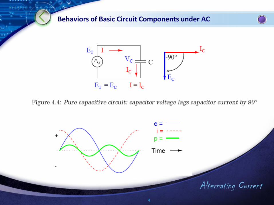
Capacitor
Capacitors react different due to the voltage level applied to them underalternating current. If the voltage level applied is greater than the voltageon a capacitor, the source charges the capacitor; in opposite case,capacitor behaves like a source.The current equation for a capacitor is:
dt
tdvCti
)()(
Alternating Current4
Behaviors of Basic Circuit Components under AC
Alternating Current5
Behaviors of Basic Circuit Components under AC
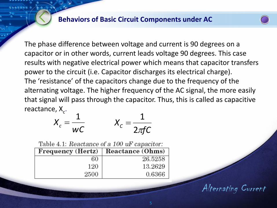
wCXc
1
fCXC
2
1
The phase difference between voltage and current is 90 degrees on a capacitor or in other words, current leads voltage 90 degrees. This caseresults with negative electrical power which means that capacitor transfers power to the circuit (i.e. Capacitor discharges its electrical charge). The ‘resistance’ of the capacitors change due to the frequency of the alternating voltage. The higher frequency of the AC signal, the more easily that signal will pass through the capacitor. Thus, this is called as capacitive reactance, Xc.

Alternating Current6
Behaviors of Basic Circuit Components under AC
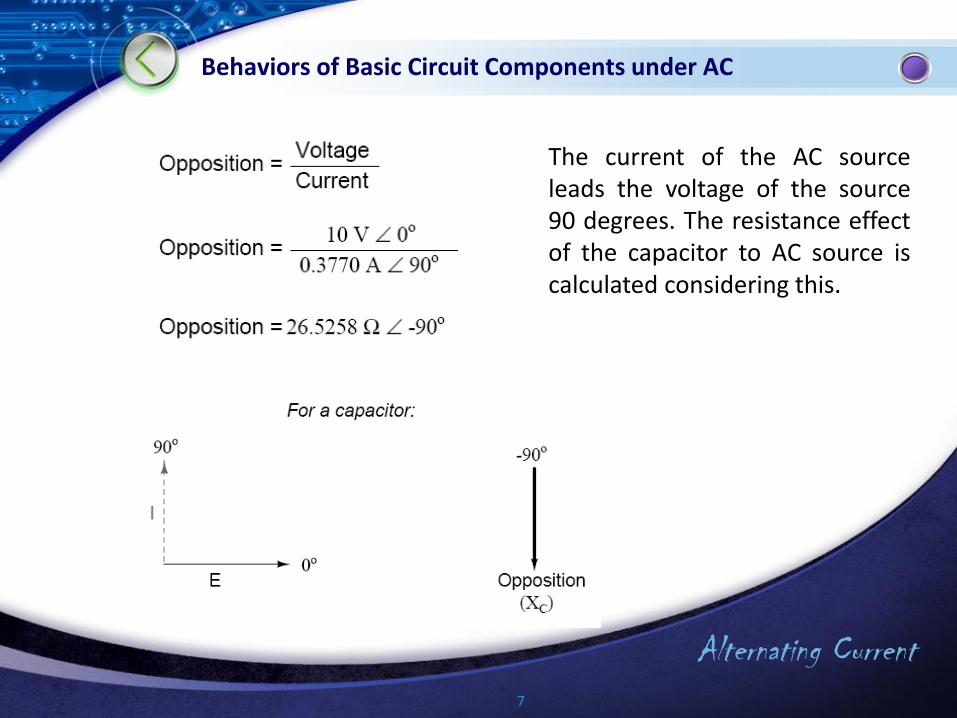
Let us examine the behavior of the capacitor in the circuit mathematically.
The current can be found using the capacitive reactance equation and the implementation of Ohm’s Law to AC easily.
Alternating Current7
Behaviors of Basic Circuit Components under AC
The current of the AC sourceleads the voltage of the source90 degrees. The resistance effectof the capacitor to AC source iscalculated considering this.

Alternating Current8
Behaviors of Basic Circuit Components under AC
jR 05 . jXc 5258260
32579993265258265 .. . jXRZ c
Adding a 5 [Ohm] resistor to this circuit, let us calculate the total effect of the resistor and the capacitor.
The total resistance in this circuit is found as:

Alternating Current9
Behaviors of Basic Circuit Components under AC
Implementing the Ohm’s Law to the circuit, the current is calculated. In this analysis, the phase of the source is always zero (0).
As it can be considered easily, the phase shift is 79.325 degrees in this circuit whereas in the circuit that has only one capacitor it was 90 degrees.
Alternating Current10
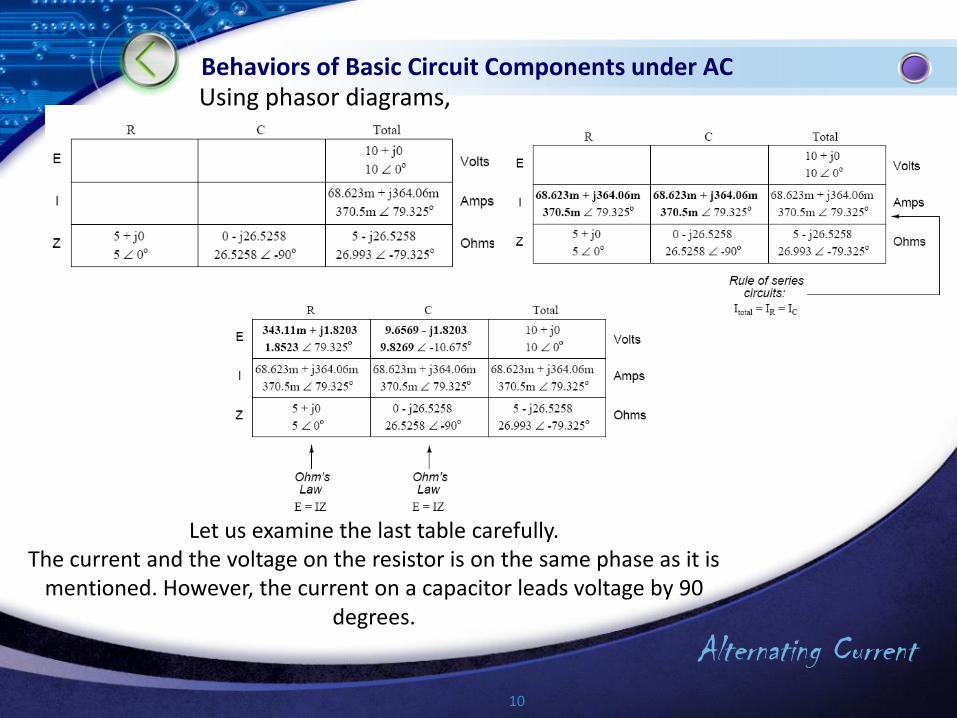
Behaviors of Basic Circuit Components under ACUsing phasor diagrams,
Let us examine the last table carefully. The current and the voltage on the resistor is on the same phase as it is
mentioned. However, the current on a capacitor leads voltage by 90 degrees.
Alternating Current11
Behaviors of Basic Circuit Components under AC
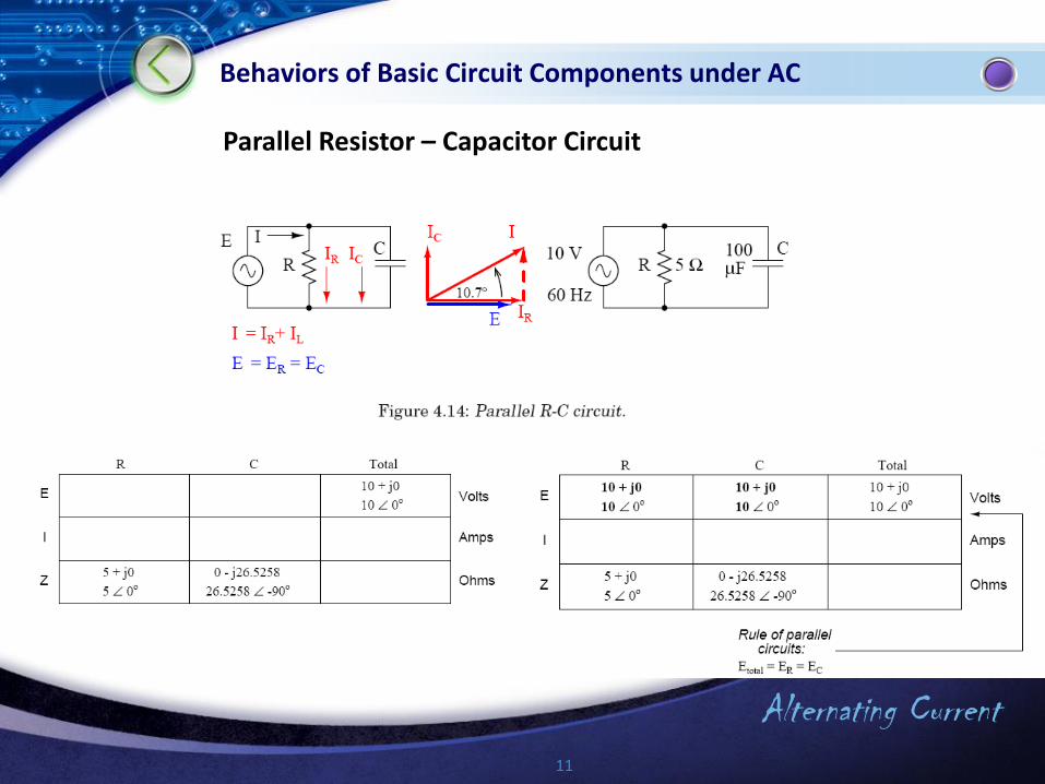
Parallel Resistor – Capacitor Circuit

Alternating Current12
Behaviors of Basic Circuit Components under AC
Alternating Current13
Behaviors of Basic Circuit Components under AC
Resistor, Reactance and Impedance
The resistance against the current can be in three types:
1. Resistor: It is the friction of electrons during motion. Its symbol is “R” andunit is [] (i.e. [Ohm]). It does not form any phase shift.
2. Reactance: It is the inertia of electrons. It occurs if there is a change involtage or current values (if an electric or magnetic field occurs). Thecapacitor and inductor are the main circuit components which this influenceis highly distinct. If there is a reactance effect in a circuit, there is also phaseshift. If the component is a capacitor, the current leads voltage by 90degrees whereas if it is an inductance, the current lags voltage by 90degrees.

Alternating Current14
Behaviors of Basic Circuit Components under AC
3. The impedance, is the strain against the current in an electrical circuit. In aother words, it is the resistance against the motion of electrons. Impedance is the total resistance and reactance effects of all components. The resistance in DC circuits is the impedance in AC’s. The AC implemented Ohm’s Law can be seen as below. Please consider that all the quantities are in complex number form in the equation below :
I
VZ
Like Ohm’s Law, other laws (Kirrschoff’s, grid theorems, etc.) used incircuit analysis can be also implemented in AC in condition of usingcomplex numbers.It is the power calculations that the AC and DC calculations differes.The next subject will be about this case.

Alternating Current15
Behaviors of Basic Circuit Components under AC
Resistor (R)Coil (L)
(Inductor)Capacitor(C)(Condenser)

Alternating Current16
Behaviors of Basic Circuit Components under AC
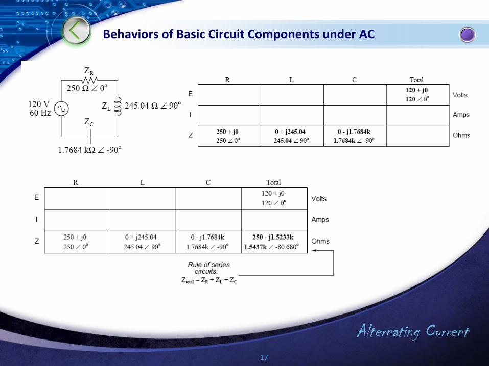
Serial R-L-C Circuits
Alternating Current17
Behaviors of Basic Circuit Components under AC

Alternating Current18
Behaviors of Basic Circuit Components under AC
Alternating Current19
Behaviors of Basic Circuit Components under AC
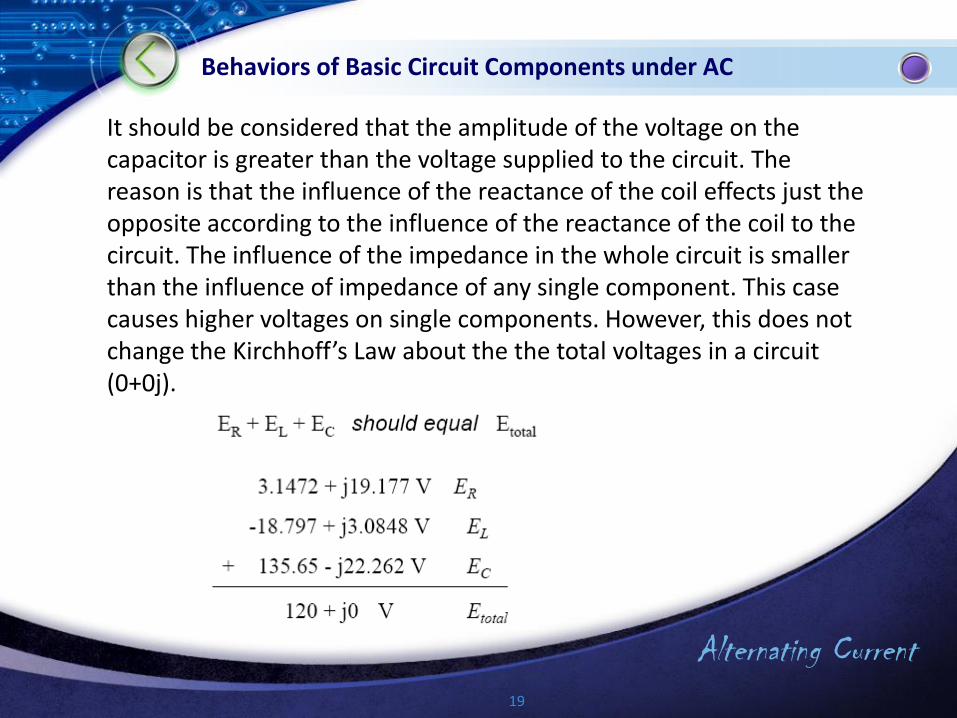
It should be considered that the amplitude of the voltage on the capacitor is greater than the voltage supplied to the circuit. The reason is that the influence of the reactance of the coil effects just the opposite according to the influence of the reactance of the coil to the circuit. The influence of the impedance in the whole circuit is smaller than the influence of impedance of any single component. This case causes higher voltages on single components. However, this does not change the Kirchhoff’s Law about the the total voltages in a circuit(0+0j).
Alternating Current20
Behaviors of Basic Circuit Components under AC
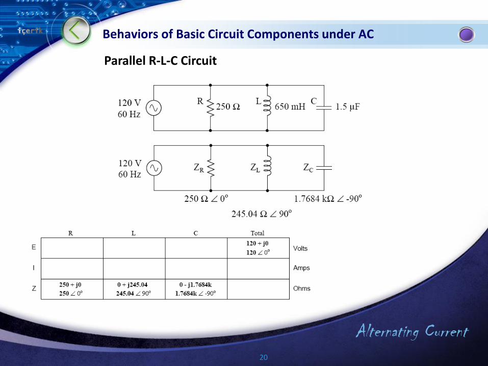
Parallel R-L-C Circuit
Alternating Current21
Behaviors of Basic Circuit Components under AC
Alternating Current22
Behaviors of Basic Circuit Components under AC
Alternating Current23
Behaviors of Basic Circuit Components under AC
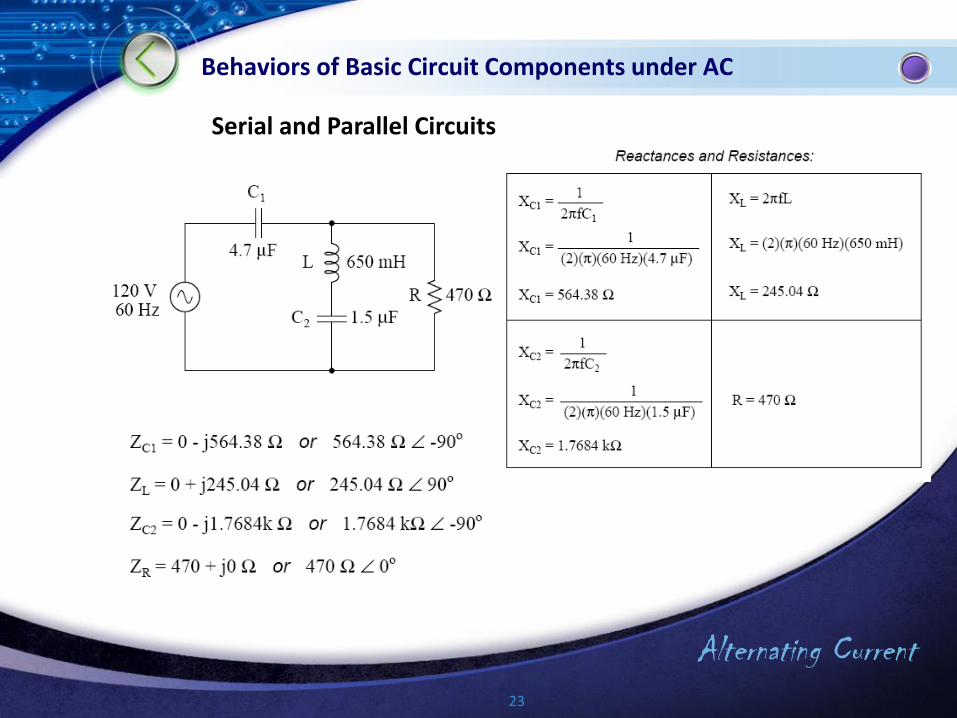
Serial and Parallel Circuits
Alternating Current24
Behaviors of Basic Circuit Components under AC
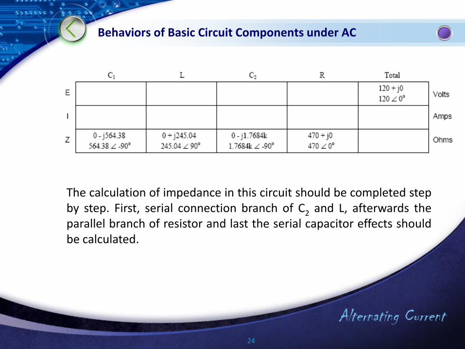
The calculation of impedance in this circuit should be completed stepby step. First, serial connection branch of C2 and L, afterwards theparallel branch of resistor and last the serial capacitor effects shouldbe calculated.

Alternating Current25
Behaviors of Basic Circuit Components under AC
Alternating Current26
Behaviors of Basic Circuit Components under AC
Alternating Current27
Behaviors of Basic Circuit Components under AC

Alternating Current28
Power in AC Circuits
Since it was mentioned, there is a phase shift between current and voltage in AC circuits. The reason is the impedance as it was stated. There are three definitions in AC circuits which are related with power. These are:
True power (active power),Reactive power, Apparent power.

Alternating Current29
Power in AC Circuits
The reactive power that is referring to the influence of reactance is:
The apparent power is the power related with the impedance:
Alternating Current30
Power in AC Circuits
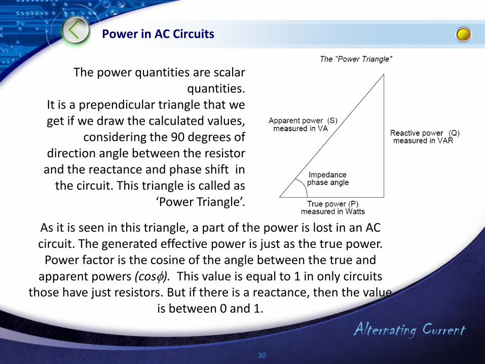
The power quantities are scalar quantities.
It is a prependicular triangle that we get if we draw the calculated values,
considering the 90 degrees of direction angle between the resistor
and the reactance and phase shift in the circuit. This triangle is called as
‘Power Triangle’.
As it is seen in this triangle, a part of the power is lost in an AC circuit. The generated effective power is just as the true power.
Power factor is the cosine of the angle between the true and apparent powers (cos). This value is equal to 1 in only circuits
those have just resistors. But if there is a reactance, then the value is between 0 and 1.
Alternating Current31
Power in AC Circuits
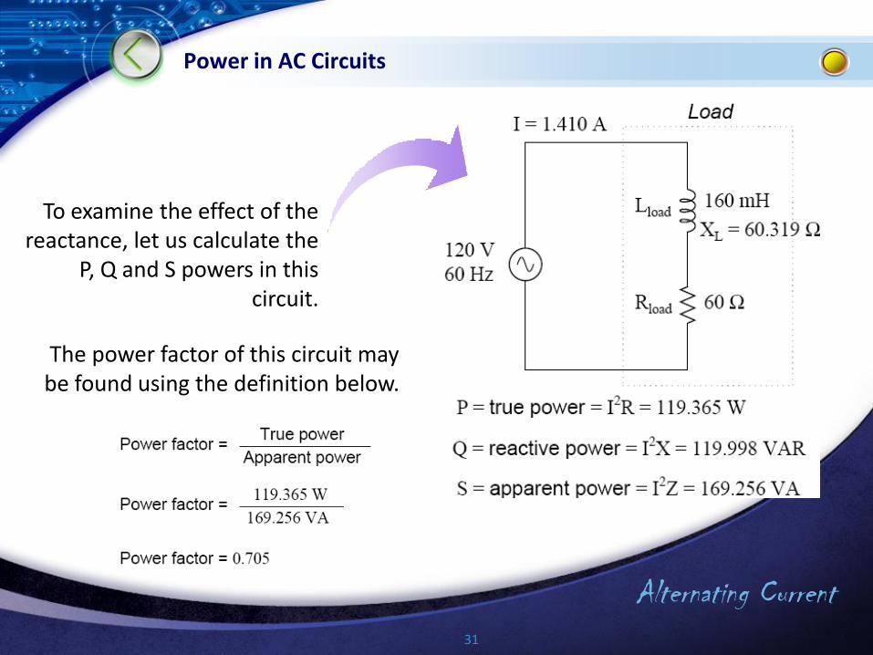
To examine the effect of the reactance, let us calculate the
P, Q and S powers in this circuit.
The power factor of this circuit maybe found using the definition below.

Alternating Current32
Power in AC Circuits
The power factor value shows that the 70.5 % of the power used fromthe grid is served for the purpose. This situation is not wanted. So, incircuit design stage, it must be noted that the power factor isapproximately equal to 1. For this reason, the capacitive andinductive ractance values should be equal to each other. If this is notpossible, a capacitor or an inductor should be externally added to thecircuit. This improvement is called as compensation.
Now, let us calculate the reactance of the same circuit.

Alternating Current33
Power in AC Circuits
The ractance in this circuit is inductive. In othe words, the coil is the reason of ractance.To compensate this, let us add a capacitor to the circuit. Using the calculations below, the capacitor value that can form a capacitive ractance to generate the same inductive ractance value but in opposite direction might be found.

Alternating Current34
Power in AC Circuits
The capacitor value found is not a standart value for
capacitors, so the closest standart value shold be
chosen (22 µF) and connected in parallel with
the circuit. Now let us examine this case:
The new impedance value is:
Alternating Current35
Power in AC Circuits
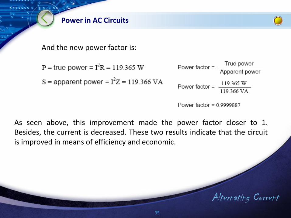
And the new power factor is:
As seen above, this improvement made the power factor closer to 1.Besides, the current is decreased. These two results indicate that the circuitis improved in means of efficiency and economic.

Alternating Current