alternateassemblies - siemens digital industries software
TRANSCRIPT

Alternate assemblies
Publication Numberspse01685


Alternate assemblies
Publication Numberspse01685
Proprietary and restricted rights notice
This software and related documentation are proprietary to Siemens ProductLifecycle Management Software Inc.
© 2011 Siemens Product Lifecycle Management Software Inc. All Rights Reserved.
Siemens and the Siemens logo are registered trademarks of Siemens AG. Solid Edgeis a trademark or registered trademark of Siemens Product Lifecycle ManagementSoftware Inc. or its subsidiaries in the United States and in other countries. Allother trademarks, registered trademarks or service marks belong to their respectiveholders.
2 Alternate assemblies spse01685
Contents
Introduction . . . . . . . . . . . . . . . . . . . . . . . . . . . . . . . . . . . . . . . . . . . . . . 1-1
Alternate Assemblies . . . . . . . . . . . . . . . . . . . . . . . . . . . . . . . . . . . . . . . . 2-1
Alternate assemblies impact on Solid Edge functionality . . . . . . . . . . . . . . . . 2-10
Define Alternate Component Command . . . . . . . . . . . . . . . . . . . . . . . . . 3-1
Activity: Creating an alternate assembly . . . . . . . . . . . . . . . . . . . . . . . . 4-1
Lesson review . . . . . . . . . . . . . . . . . . . . . . . . . . . . . . . . . . . . . . . . . . . . . 5-1
Answers . . . . . . . . . . . . . . . . . . . . . . . . . . . . . . . . . . . . . . . . . . . . . . . . . . 0-1
Lesson summary . . . . . . . . . . . . . . . . . . . . . . . . . . . . . . . . . . . . . . . . . . . 6-1
Activity: Creating an alternate assembly . . . . . . . . . . . . . . . . . . . . . . . . A-1
Create an alternate assembly for a valve . . . . . . . . . . . . . . . . . . . . . . . . . . . A-1Modify the Type 1 Closed family member . . . . . . . . . . . . . . . . . . . . . . . . . . . A-3Create the member Type 2 Open . . . . . . . . . . . . . . . . . . . . . . . . . . . . . . . . . A-7Observe results . . . . . . . . . . . . . . . . . . . . . . . . . . . . . . . . . . . . . . . . . . . . A-12Finish defining the Type 2 Open member . . . . . . . . . . . . . . . . . . . . . . . . . . A-13Create a new family member . . . . . . . . . . . . . . . . . . . . . . . . . . . . . . . . . . . A-17Observe results . . . . . . . . . . . . . . . . . . . . . . . . . . . . . . . . . . . . . . . . . . . . A-22Create family member named Type 3 Open Reverse Handle. . . . . . . . . . . . . A-23Draft family of assembly members . . . . . . . . . . . . . . . . . . . . . . . . . . . . . . . A-26Activity summary . . . . . . . . . . . . . . . . . . . . . . . . . . . . . . . . . . . . . . . . . . . A-27
spse01685 Alternate assemblies 3


Lesson
1 Introduction
Welcome to self paced training for Solid Edge. This course is designed to educate youin the use of Solid Edge. The course is self-paced and contains instruction followedby activities.
Solid Edge self-paced courses• spse01510—Sketching
• spse01515—Constructing base features
• spse01520—Moving and rotating faces
• spse01525—Working with face relationships
• spse01530—Constructing treatment features
• spse01535—Constructing procedural features
• spse01536—Modeling synchronous and ordered features
• spse01540—Modeling assemblies
• spse01545—Creating detailed drawings
• spse01546—Sheet metal design
• spse01550—Practicing your skills with projects
• spse01560—Modeling a Part Using Surfaces
• spse01610—Solid Edge frame design
• spse01640—Assembly patterning
• spse01645—Assembly systems libraries
• spse01650—Working with large assemblies
• spse01655—Revising assemblies
• spse01660—Assembly reports
• spse01665—Replacing parts in an assembly
• spse01670—Designing in the context of an assembly
spse01685 Alternate assemblies 1-1
Lesson 1 Introduction
• spse01675—Assembly features
• spse01680—Inspecting assemblies
• spse01685—Alternate assemblies
• spse01686—Adjustable parts and assemblies
• spse01690—Virtual components in assemblies
• spse01691—Exploding assemblies
• spse01692—Rendering assemblies
• spse01693—Animating assemblies
• spse01695—XpresRoute (tubing)
• spse01696—Creating a Wire Harness with Harness Design
• spse01424—Working with Solid Edge Embedded Client
Start with the tutorials
Self-paced training begins where tutorials end. Tutorials are the quickest way foryou to become familiar with the basics of using Solid Edge. If you do not have anyexperience with Solid Edge, please start by working through the tutorials for basicpart modeling and editing before starting this self-paced training.
1-2 Alternate assemblies spse01685
Lesson
2 Alternate Assemblies
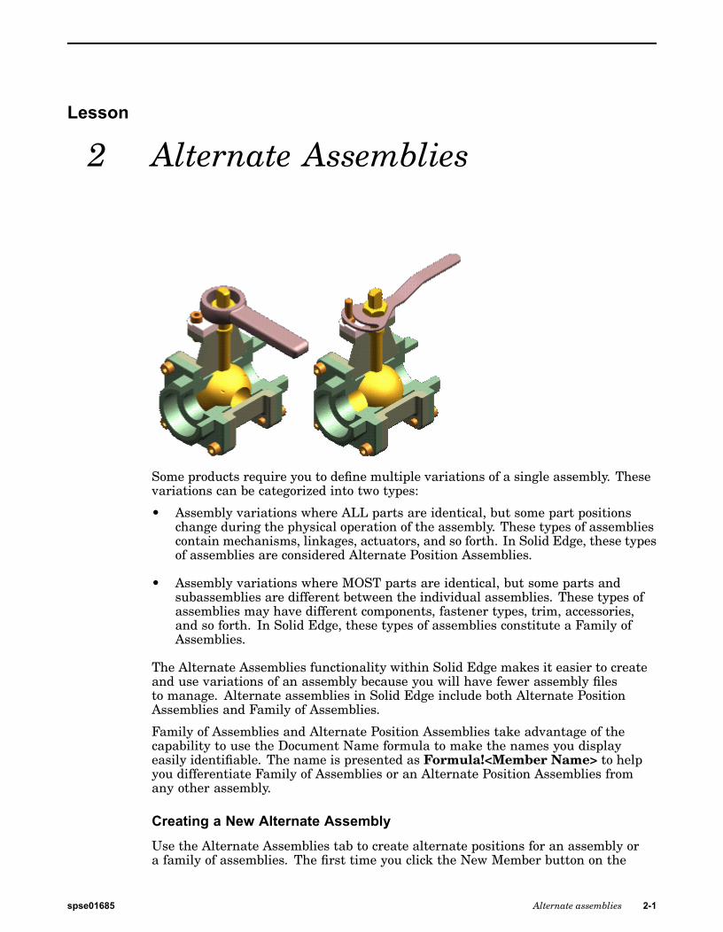
Some products require you to define multiple variations of a single assembly. Thesevariations can be categorized into two types:
• Assembly variations where ALL parts are identical, but some part positionschange during the physical operation of the assembly. These types of assembliescontain mechanisms, linkages, actuators, and so forth. In Solid Edge, these typesof assemblies are considered Alternate Position Assemblies.
• Assembly variations where MOST parts are identical, but some parts andsubassemblies are different between the individual assemblies. These types ofassemblies may have different components, fastener types, trim, accessories,and so forth. In Solid Edge, these types of assemblies constitute a Family ofAssemblies.
The Alternate Assemblies functionality within Solid Edge makes it easier to createand use variations of an assembly because you will have fewer assembly filesto manage. Alternate assemblies in Solid Edge include both Alternate PositionAssemblies and Family of Assemblies.
Family of Assemblies and Alternate Position Assemblies take advantage of thecapability to use the Document Name formula to make the names you displayeasily identifiable. The name is presented as Formula!<Member Name> to helpyou differentiate Family of Assemblies or an Alternate Position Assemblies fromany other assembly.
Creating a New Alternate Assembly
Use the Alternate Assemblies tab to create alternate positions for an assembly ora family of assemblies. The first time you click the New Member button on the
spse01685 Alternate assemblies 2-1
Lesson 2 Alternate Assemblies
Alternate Assemblies tab, the Alternate Assemblies Table dialog box is displayed.You must specify whether the assembly will be converted to (A) a family ofassemblies or (B) an assembly containing alternate positions. Once the assembly hasbeen converted, it cannot be changed from (A) to (B) or from (B) to (A).
Note
Ensure that an archive copy of the assembly you are converting exists. Youcan use the Save As command to create a new working copy of the assemblydocument before converting it to an alternate assembly.
After you specify the alternate assembly type, you define the names for the firsttwo members. When you click OK, the second member is made the active memberon the Alternate Assemblies tab. You can then proceed to define the individualmember characteristics.
Alternate Assembly Edit Table dialog box
The Alternate Assembly Edit Table dialog box, available when you click the EditTable button on the Alternate Assembly tab performs many of the same functions asthe Alternate Assembly tab. Additionally, the Alternate Assembly Edit Table dialogbox also allows you to view the member characteristics of all the alternate assemblymembers simultaneously, which you cannot do using the Alternate Assemblies tab.For example, you can see which parts are excluded for all members simultaneously.
The buttons along the top of the Alternate Assembly Edit Table dialog box allow youto perform common functions such as creating new members, deleting members,activating a member, saving a member as a new assembly document, and so forth.You can also print the table to a printer you specify and copy and paste data from theAlternate Assembly Edit Table dialog box to a spreadsheet.
A Preview window is also available with the Alternate Assembly Edit Table dialogbox. The Preview window displays the currently selected member.
Some functionality that is available on the Alternate Assembly tab is not availablewith the Alternate Assembly Edit Table dialog box. For example, you can onlyexclude relationships using the Alternate Assembly tab.
Working with Alternate Assemblies
After defining the first two members of an alternate assembly, you can work withthe alternate assembly using the Alternate Assemblies tab or you can click the EditTable button on the Alternate Assemblies tab to display the Alternate AssembliesEdit Table dialog box, which is a table-driven user interface for working withalternate assemblies that performs similar to a spreadsheet application.
Note
Adding Members to an existing Alternate Assembly
After you have converted an assembly to an alternate assembly, you can addadditional members using the New button on the Alternate Assemblies tab or theAlternate Assemblies Edit Table dialog box. The characteristics of the new memberare a copy of the currently active member.
2-2 Alternate assemblies spse01685
Alternate Assemblies
Renaming Alternate Assembly members
You cannot rename an alternate assembly member. If you want to change thename of an existing member, you can make it the active member, then create a newmember with the name you want. You can then delete the other member.
Note
You cannot delete the default member, which is the first member created. Itmay be helpful to name the first member Default, or something similar so thatlater you will know that this member cannot be deleted.
Alternate Position Assemblies
As stated earlier, alternate position assemblies require that all parts in the variousmember assemblies are the same. The only differences you can define betweenindividual members are for assembly variables, such as the offset values forassembly relationships and the numeric value for sketch-based dimensions. Theoptions available for alternate position assemblies are discussed in more detail inthe following sections.
Family of Assemblies
For a family of assemblies, you can define the following types of variations betweenthe individual family members:
• Offset values for assembly relationships
• Occurrence overrides
• Excluded occurrences
• Excluded relationships
• Excluded assembly features
• Excluded frames
• Excluded piping routes
• Excluded pattern occurrences
• Excluded fasteners
Global Modifications and Local Modifications
When working with alternate assemblies, you can specify whether the modificationsyou make affect only the active member, or all members. Modifications that affectonly the active member are called local modifications, and modifications that affectall members are global modifications.
When you set the Apply Edits To All Members option on the Alternate Assembliestab, the modifications you make are globally applied to all members.
When you clear the Apply Edits To All Members option on the Alternate Assembliestab, the modifications you make are locally applied to only the active member.
spse01685 Alternate assemblies 2-3
Lesson 2 Alternate Assemblies
For example, when the Apply Edits To All members options is cleared, you candelete a part from one member of a family of assemblies, then place a differentpart for that member.
Note
Depending on whether you are working with an alternate position assemblyor a family of assemblies, some operations may not be available both locallyand globally.
Activating a Member
Only one member of an alternate assembly can be active. The currently activemember is displayed in the Active Member list. You can activate another memberby selecting it from the Active Member list on the Alternate Assemblies tab, or youcan select the member column on the Alternate Assemblies Edit Table dialog box,then click the Activate Member button.
Defining Member Variable Values
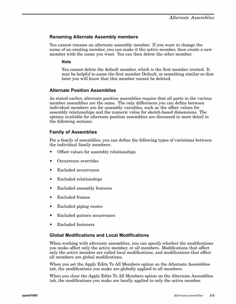
You can define different values for an assembly variable using the Member Variablesoption on the Alternate Assemblies tab. The variable can be associated with anassembly relationship or any other assembly variable. For example, you canreposition parts by defining different values for an angle relationship for individualalternate assembly members.
On the Alternate Assemblies tab, set the Member Variables option. Then in theVariable Table, select the variable that you want to add to the Member Variableslist. On the Alternate Assemblies tab, click the Add Variables button. The variableis added to all current members. You can then activate a member, and modify thevalue for the variable. This option is available for both types of alternate assemblies.
You can determine the variable name for an assembly relationship by positioningyour cursor over the relationship in the bottom pane of PathFinder. The relationshipname is then displayed in the message box on the bottom right side of the SolidEdge window.
Overriding Occurrences
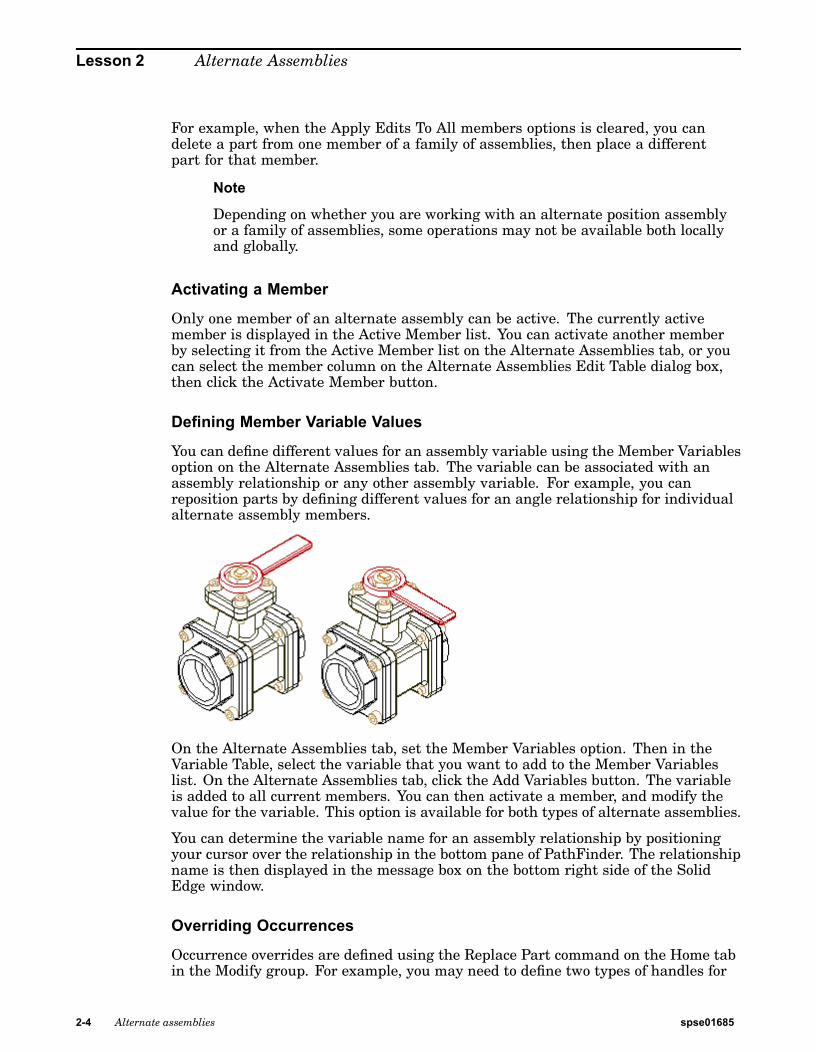
Occurrence overrides are defined using the Replace Part command on the Home tabin the Modify group. For example, you may need to define two types of handles for
2-4 Alternate assemblies spse01685
Alternate Assemblies
different members. One member has the original handle, and another member hasthe replacement handle.
On the Alternate Assemblies tab, activate the member requiring a new handle, thenensure the Apply Edits To All Members option is cleared. You can then use theReplace Part command to replace the original handle part with the new handlepart for only the active member.
For alternate position assemblies, this option can only be applied globally, sincealternate position assemblies require that all parts are the same for all members.For a family of assemblies, this option can be applied globally or locally.
You can also define occurrence overrides for subassemblies within the activeassembly. When replacing subassemblies, the replacement subassembly can also bean alternate assembly. When the replacement subassembly is an alternate assembly,you can select the member you want using the Assembly Member dialog box.
Excluding Occurrences
Excluded occurrences are defined by deleting parts for one member, but not others.On the Alternate Assemblies tab, activate the member for which you want to deletea part. Select the part you want to delete in PathFinder, then press Delete. The partis deleted only for the active member, and is added to the Excluded Occurrences list.
For alternate position assemblies, this option can only be applied globally, sincealternate position assemblies require that all parts are the same for all members.For a family of assemblies, this option can be applied globally or locally.
Note
If you are working globally (the Apply Edits To All Members option is set),when you delete a part, the part is physically deleted from the assembly andthe part is NOT added to the Excluded Occurrences list.
Excluding Relationships
Excluding relationships for a member allows you to reposition parts using newrelationships. For example, you may need to reposition a part for one member byusing faces or relationships different from the original member.
spse01685 Alternate assemblies 2-5
Lesson 2 Alternate Assemblies
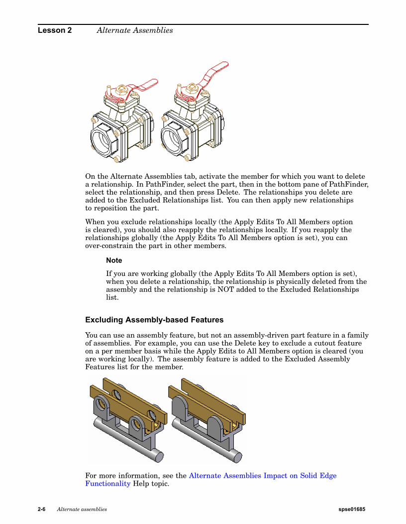
On the Alternate Assemblies tab, activate the member for which you want to deletea relationship. In PathFinder, select the part, then in the bottom pane of PathFinder,select the relationship, and then press Delete. The relationships you delete areadded to the Excluded Relationships list. You can then apply new relationshipsto reposition the part.
When you exclude relationships locally (the Apply Edits To All Members optionis cleared), you should also reapply the relationships locally. If you reapply therelationships globally (the Apply Edits To All Members option is set), you canover-constrain the part in other members.
Note
If you are working globally (the Apply Edits To All Members option is set),when you delete a relationship, the relationship is physically deleted from theassembly and the relationship is NOT added to the Excluded Relationshipslist.
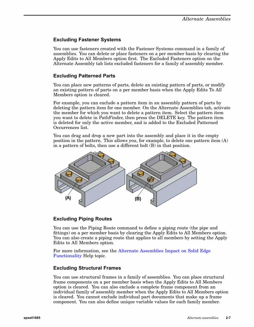
Excluding Assembly-based Features
You can use an assembly feature, but not an assembly-driven part feature in a familyof assemblies. For example, you can use the Delete key to exclude a cutout featureon a per member basis while the Apply Edits to All Members option is cleared (youare working locally). The assembly feature is added to the Excluded AssemblyFeatures list for the member.
For more information, see the Alternate Assemblies Impact on Solid EdgeFunctionality Help topic.
2-6 Alternate assemblies spse01685
Alternate Assemblies
Excluding Fastener Systems
You can use fasteners created with the Fastener Systems command in a family ofassemblies. You can delete or place fasteners on a per member basis by clearing theApply Edits to All Members option first. The Excluded Fasteners option on theAlternate Assembly tab lists excluded fasteners for a family of assembly member.
Excluding Patterned Parts
You can place new patterns of parts, delete an existing pattern of parts, or modifyan existing pattern of parts on a per member basis when the Apply Edits To AllMembers option is cleared.
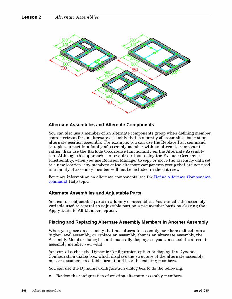
For example, you can exclude a pattern item in an assembly pattern of parts bydeleting the pattern item for one member. On the Alternate Assemblies tab, activatethe member for which you want to delete a pattern item. Select the pattern itemyou want to delete in PathFinder, then press the DELETE key. The pattern itemis deleted for only the active member, and is added to the Excluded PatternedOccurrences list.
You can drag and drop a new part into the assembly and place it in the emptyposition in the pattern. This allows you, for example, to delete one pattern item (A)in a pattern of bolts, then use a different bolt (B) in that position.
Excluding Piping Routes
You can use the Piping Route command to define a piping route (the pipe andfittings) on a per member basis by clearing the Apply Edits to All Members option.You can also create a piping route that applies to all members by setting the ApplyEdits to All Members option.
For more information, see the Alternate Assemblies Impact on Solid EdgeFunctionality Help topic.
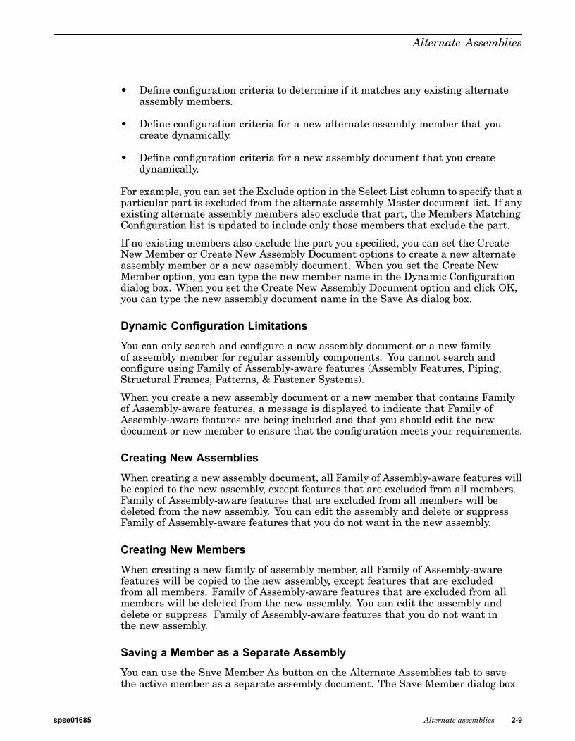
Excluding Structural Frames
You can use structural frames in a family of assemblies. You can place structuralframe components on a per member basis when the Apply Edits to All Membersoption is cleared. You can also exclude a complete frame component from anindividual family of assembly member when the Apply Edits to All Members optionis cleared. You cannot exclude individual part documents that make up a framecomponent. You can also define unique variable values for each family member.
spse01685 Alternate assemblies 2-7
Lesson 2 Alternate Assemblies
Alternate Assemblies and Alternate Components
You can also use a member of an alternate components group when defining membercharacteristics for an alternate assembly that is a family of assemblies, but not analternate position assembly. For example, you can use the Replace Part commandto replace a part in a family of assembly member with an alternate component,rather than use the Exclude Occurrence functionality on the Alternate Assemblytab. Although this approach can be quicker than using the Exclude Occurrencefunctionality, when you use Revision Manager to copy or move the assembly data setto a new location, any members of the alternate components group that are not usedin a family of assembly member will not be included in the data set.
For more information on alternate components, see the Define Alternate Componentscommand Help topic.
Alternate Assemblies and Adjustable Parts
You can use adjustable parts in a family of assemblies. You can edit the assemblyvariable used to control an adjustable part on a per member basis by clearing theApply Edits to All Members option.
Placing and Replacing Alternate Assembly Members in Another Assembly
When you place an assembly that has alternate assembly members defined into ahigher level assembly, or replace an assembly that is an alternate assembly, theAssembly Member dialog box automatically displays so you can select the alternateassembly member you want.
You can also click the Dynamic Configuration option to display the DynamicConfiguration dialog box, which displays the structure of the alternate assemblymaster document in a table format and lists the existing members.
You can use the Dynamic Configuration dialog box to do the following:
• Review the configuration of existing alternate assembly members.
2-8 Alternate assemblies spse01685
Alternate Assemblies
• Define configuration criteria to determine if it matches any existing alternateassembly members.
• Define configuration criteria for a new alternate assembly member that youcreate dynamically.
• Define configuration criteria for a new assembly document that you createdynamically.
For example, you can set the Exclude option in the Select List column to specify that aparticular part is excluded from the alternate assembly Master document list. If anyexisting alternate assembly members also exclude that part, the Members MatchingConfiguration list is updated to include only those members that exclude the part.
If no existing members also exclude the part you specified, you can set the CreateNew Member or Create New Assembly Document options to create a new alternateassembly member or a new assembly document. When you set the Create NewMember option, you can type the new member name in the Dynamic Configurationdialog box. When you set the Create New Assembly Document option and click OK,you can type the new assembly document name in the Save As dialog box.
Dynamic Configuration Limitations
You can only search and configure a new assembly document or a new familyof assembly member for regular assembly components. You cannot search andconfigure using Family of Assembly-aware features (Assembly Features, Piping,Structural Frames, Patterns, & Fastener Systems).
When you create a new assembly document or a new member that contains Familyof Assembly-aware features, a message is displayed to indicate that Family ofAssembly-aware features are being included and that you should edit the newdocument or new member to ensure that the configuration meets your requirements.
Creating New Assemblies
When creating a new assembly document, all Family of Assembly-aware features willbe copied to the new assembly, except features that are excluded from all members.Family of Assembly-aware features that are excluded from all members will bedeleted from the new assembly. You can edit the assembly and delete or suppressFamily of Assembly-aware features that you do not want in the new assembly.
Creating New Members
When creating a new family of assembly member, all Family of Assembly-awarefeatures will be copied to the new assembly, except features that are excludedfrom all members. Family of Assembly-aware features that are excluded from allmembers will be deleted from the new assembly. You can edit the assembly anddelete or suppress Family of Assembly-aware features that you do not want inthe new assembly.
Saving a Member as a Separate Assembly
You can use the Save Member As button on the Alternate Assemblies tab to savethe active member as a separate assembly document. The Save Member dialog box
spse01685 Alternate assemblies 2-9
Lesson 2 Alternate Assemblies
allows you to specify a document name and location for the new assembly document.The new assembly document is a regular assembly document.
Defining Member Properties
When an assembly has been converted to a family of assemblies, you can use theProperty Manager command to define properties for the parts and subassembliesfor individual family members. For example, you can define a document number,revision number, and project name for individual members. These properties areused when you create a parts list for the family member in the Draft environmentor an assembly report.
Displaying Parts in Alternate Assemblies
When you change the display of a part in an alternate assembly member, thechange only affects the active member, regardless of whether the Apply Edits To AllMembers option is set or cleared. For example, if you hide a part in one member,the same part in other members will remain displayed, even if the Apply EditsTo All Members option is set.
Alternate assemblies impact on Solid Edge functionalityWhen you create alternate assemblies in Solid Edge, functionality in other areas ofthe Solid Edge product is impacted. This impact is typically felt as a restriction onwhether certain functionality is available when an assembly has been converted toan alternate assembly. This topic documents this impact in one central location.
3D section views
You can only create new 3D section views with the Section command when the ApplyEdits to All Members option on the Alternate Assemblies tab is set.
Adjustable parts
You can use adjustable parts in a family of assemblies. You can edit the assemblyvariable used to control an adjustable part on a per member basis by clearing theApply Edits to All Members option.
Assembly-based features
Because there are two distinct types of assembly-based features: assembly features,and assembly-driven part features, they are discussed separately.
Assembly features
You can use assembly features in a family of assemblies. For example, you can usethe Delete key to exclude a cutout feature on a per member basis while the ApplyEdits to All Members option is cleared (you are working locally). The assemblyfeature is added to the Excluded Assembly Features list for the member.
Because it is possible to create inter-part links when creating an assembly feature,and alternate assemblies do not allow inter-part links, the inter-part links aredeleted when you convert the assembly to an alternate assembly. For example, if
2-10 Alternate assemblies spse01685
Alternate Assemblies
you place a positioning dimension or geometric relationship between a profile for anassembly feature and a part edge, an inter-part link is created.
To delete the inter-part links, any dimensions and geometric relationships that wereplaced to part edges are deleted. You can add the dimensions and relationships to anassembly sketch or an assembly reference plane to constrain the profile.
Assembly-driven part features
With assembly-driven part features, the profile geometry (such as lines, arcs, andcircles) is copied to the part documents that were modified by the feature. Then theassembly-driven part feature and all dimensions and relationships are deleted fromthe assembly document. You can open the part documents and add the necessarydimensions and relationships to constrain the profile.
For more information, see the Assembly-based Features Help topic.
Assembly patterns of parts
You can place new patterns, and delete or modify existing patterns on a per memberbasis when the Apply Edits to All Members option is cleared (you are workinglocally). For example, you can use the DELETE key to exclude one bolt in a patternof bolts when working locally. You can then place a different bolt in that positionon the pattern.
When you delete an entire pattern of parts, it is added to the Excluded PatternOccurrences list on the Alternate Assemblies tab. When you delete a pattern item, itis added to the Excluded Occurrences list.
You can only modify the inputs for a pattern of parts when the Apply Edits to AllMembers option is set (you are working globally). For example, if an assemblypattern of parts originally included a bolt and nut, you cannot modify the pattern toadd a washer to the pattern unless you are working globally.
A Drop Pattern command is available on the shortcut menu when the Apply Editsto All Members option is set (you are working globally). This command allows youto drop an assembly pattern and the parts that were contained in the pattern arenow positioned using a ground relationship. Dropping a pattern allows you to placea part formerly contained in the pattern onto the Excluded Occurrences list whenworking locally.
Check interference
The Save As Part option on the Interference Options dialog box is not available whenthe Apply Edits to All Members option is set. If an interfering volume is created asa part while working in the local mode (the Apply Edits to All Members option iscleared), the part is added to the Excluded Occurrence list for the inactive members.
Construction elements
Coordinate systems, layouts and reference planes can be edited only when the ApplyEdits to All Members option is set.
spse01685 Alternate assemblies 2-11
Lesson 2 Alternate Assemblies
Display configurationsDisplay configurations are available when working with alternate assemblies. Thebehavior of display configurations based on whether you specify that the alternateassembly is a family of assemblies or an alternate position assembly.
Family of assemblies
For a family of assemblies, a display configuration is member-specific. In otherwords, the family of assembly member which is active when you create thedisplay configuration is the only member in which you can use the displayconfiguration later. The Assembly Configuration list on the Select Tool commandbar filters the available display configurations automatically.
Alternate position assemblies
For alternate position assemblies, display configurations are not member-specific.In other words, you can use any display configuration for any active member.The Assembly Configuration list on the Select Tool command bar displays all thedisplay configurations.
Disperse commandThe Disperse command is only available when the Apply Edits to All Membersoption is set.
Fastener systemsYou can use fasteners created with the Fastener Systems command in a familyof assemblies on a per member basis. You can delete or place fasteners to onlythe active member by clearing the Apply Edits to All Members option first. TheExcluded Fasteners option on the Alternate Assembly tab lists excluded fasteners foran alternate assembly member.
In-place activating alternate assembliesWhen an alternate assembly member has been placed in a higher level assembly,you cannot in-place activate the alternate assembly. You can use the Open commandon the shortcut menu in PathFinder to open the assembly instead.
Inter-part relationshipsBecause inter-parts links are not allowed in an alternate assembly, when you createthe first two members of an alternate assembly that contains inter-part links, adialog box is displayed to warn you that inter-part links will be deleted. You can usethe Inter-Part Manager dialog box to review the inter-part links.
Motor definitionsYou can only create and edit motors when the Apply Edits to All Members optionis set.
If a motor is applied to a part, and that part is deleted when the Apply Edits to AllMembers option is set, the motor will show as failed in all members.
If a motor is applied to a part, and that part is deleted when the Apply Edits toAll Members option is cleared, the motor object is removed from the display in
2-12 Alternate assemblies spse01685
Alternate Assemblies
PathFinder. If an excluded part which is a motor is re-included in a member, themotor will be displayed in Assembly Pathfinder.
Occurrence properties
The Reference Options on the Occurrence Options dialog box are available only whenthe Apply Edits to All Members option is set.
Opening files
The default alternate assembly member is opened when a file is opened usingWindows Explorer. When opening a file using the Open File dialog box in SolidEdge, the Assembly Member dialog box is displayed so you can select the assemblymember you want.
Part copies
When creating a part copy using an alternate assembly document, the AssemblyMember dialog box is displayed so you can select the assembly member you want.
If you convert an existing assembly to an alternate assembly, and that assembly wasused as the basis for a part copy document, the default member is used.
Path segment commands
The commands you use to create 3D path segments for tubes, wires, and pipingroutes are available only when the Apply Edits to All Members option is set.For example, the Path Xpres, Line Segment, Split Segment, and Move Segmentcommands are available only when the Apply Edits to All Members option is set (youare working globally).
This restriction also applies to the commands you use to dimension 3D pathsegments, such as SmartDimension. After you create and dimension the 3-D paths,you can clear the Apply Edits to All Members option to define tubes, wires, andpiping routes on a per member basis as long as you follow the guidelines for tubes,wires, and pipe routes discussed elsewhere in this document.
Piping routes
You can use the Piping Route command to define a piping route (the pipe and fittings)on a per member basis by clearing the Apply Edits to All Members option. You canalso create a piping route that applies to all members by setting the Apply Edits toAll Members option. After you create a piping route, the 3-D path segments you usedare automatically hidden to prevent you from reusing the selected segments on adifferent piping path. It is recommended that you do not reuse path segments tocreate unique piping routes for individual alternate assembly members.
Although you can redisplay the segments using the Show All Paths command, andthen reuse them, in some cases, reusing segments can result in a piping route withpiping couplings you may not expect.
For example, when you connect one line segment to the midpoint of a second linesegment, the second line segment is automatically split at the midpoint. When youdefine the piping route, a coupling is using to connect the pipe components togetherwhere they meet.
spse01685 Alternate assemblies 2-13
Lesson 2 Alternate Assemblies
If you then try to create a new piping route for a different alternate assemblymember that does not include the first segment, a coupling will be added to connectthe segments of the line that was split. Typically, a coupling is not wanted in thissituation. To avoid this, draw a separate line segment in this type of situation.
Placing parts in assemblies
Part placement obeys the current setting of the Apply Edits to All Members option.When this option is set, the part is added to all assembly members. When thisoption is cleared, the part is added to the active member, and the part is added tothe Excluded Occurrence list for the other members.
When you place a subassembly that has alternate assembly members defined intoa higher level assembly, the Assembly Member dialog box is displayed so you canselect the member you want.
Reorder command
This command is available only when the Apply Edits to All Members option is set.
Reports
When you use the Reports command to create an assembly report from within theassembly, the report is created for the active member.
When you use the Reports command to create an assembly report from withinWindows Explorer, the FOA Member Names dialog box is displayed so you can selectthe member you want to create the report for.
Revision Manager
When an alternate assembly is opened in Revision Manager, the file list is acompilation of all the members contained in the assembly.
When an assembly containing a subassembly that is an alternate assembly is openedin Revision Manager, the subassembly reflects the file set contained in the memberthat was placed into the higher level assembly.
Simply Motion
The Motion command is not available for an alternate assembly. You can use theSave Member As command on the Alternate Assemblies tab to save an alternateassembly member as a normal assembly document. You can then access the SimplyMotion environment.
Simplified assemblies
You cannot create a simplified representation of an assembly that is an alternateassembly. If you have already simplified an assembly, then try to convert theassembly to an alternate assembly, a message is displayed to warn you that thesimplified assembly representation will be deleted if you continue.
2-14 Alternate assemblies spse01685
Alternate Assemblies
Structural framesYou can use structural frames in a family of assemblies. You can place structuralframe components on a per member basis when the Apply Edits to All Membersoption is cleared (you are working locally)
You can also exclude a complete frame component from an individual family ofassembly member when the Apply Edits to All Members option is cleared. Youcannot exclude individual part documents that make up a frame component.
Transfer commandThe Transfer command is only available when the Apply Edits to All Membersoption is set.
Undo commandThe Undo command is not available when working with an alternate assembly.
XpresRouteEach tube that is created in an alternate assembly file must be controlled by a singlemember. The reason for this is that the parts that contain ports that drive the tubepath (that in turn drives the tube) can be positioned differently in various membersthrough techniques involving excluded relationships and overridden variables,causing the potential for any one tube part to assume different geometries dependingon the active member. The following rules govern XpresRoute behavior:
• When a tube part is created, it is created in the context of a single member. Thetube part is automatically placed on the exclude list of all other members, butthe tube part is hidden in the exclude list so that it cannot be removed from theexclude list of non-driving members.
• Occurrence one of a tube created through XpresRoute is always the drivenoccurrence, and may only exist within the driving member.
• All commands which create and manipulate tube path elements are availablewhen working globally (the Apply Edits to All Members option is set).
• The Tube command is available only when the Apply Edits to All Membersoption is cleared (you are working locally).
• All tube paths are seen in all members.
• If an assembly that contains a tube part that is driven by a path existing inthe file, and that assembly is converted into a alternate assembly, the defaultmember becomes the driving member for the tube. The tube is automaticallyplaced on the exclude list and hidden in the second member. If you want toinclude this tube part in other members, you can place it using the Parts Librarytab. This places an occurrence that is not a child and therefore will not trigger anupdate of itself when the Update All command is run. This assures that a tubepart is not updated unless the member in which it was created is currently active,and consequently, each tube part is driven only in context of a single member.
• When a new member is created while the active member contains a tube that isdriven by that member, the driven tube is placed on the exclude list of the new
spse01685 Alternate assemblies 2-15

Lesson 2 Alternate Assemblies
member and hidden on the list so that it cannot be taken off the list. The effectwill be that the tube part does not appear in the new member.
• In version 17, if you convert an assembly to an alternate assembly after youcreate tube paths and tubes in XpresRoute, the links to the tubes will be broken.If you convert the assembly to an alternate assembly before you create tubepaths or tubes, the links to the tubes you create later will function properly.
2-16 Alternate assemblies spse01685
Lesson
3 Define Alternate ComponentCommand
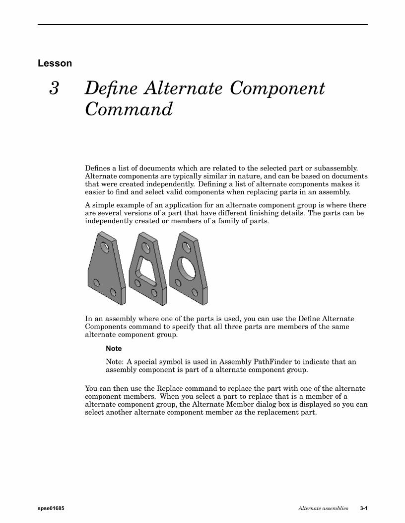
Defines a list of documents which are related to the selected part or subassembly.Alternate components are typically similar in nature, and can be based on documentsthat were created independently. Defining a list of alternate components makes iteasier to find and select valid components when replacing parts in an assembly.
A simple example of an application for an alternate component group is where thereare several versions of a part that have different finishing details. The parts can beindependently created or members of a family of parts.
In an assembly where one of the parts is used, you can use the Define AlternateComponents command to specify that all three parts are members of the samealternate component group.
Note
Note: A special symbol is used in Assembly PathFinder to indicate that anassembly component is part of a alternate component group.
You can then use the Replace command to replace the part with one of the alternatecomponent members. When you select a part to replace that is a member of aalternate component group, the Alternate Member dialog box is displayed so you canselect another alternate component member as the replacement part.
spse01685 Alternate assemblies 3-1
Lesson 3 Define Alternate Component Command
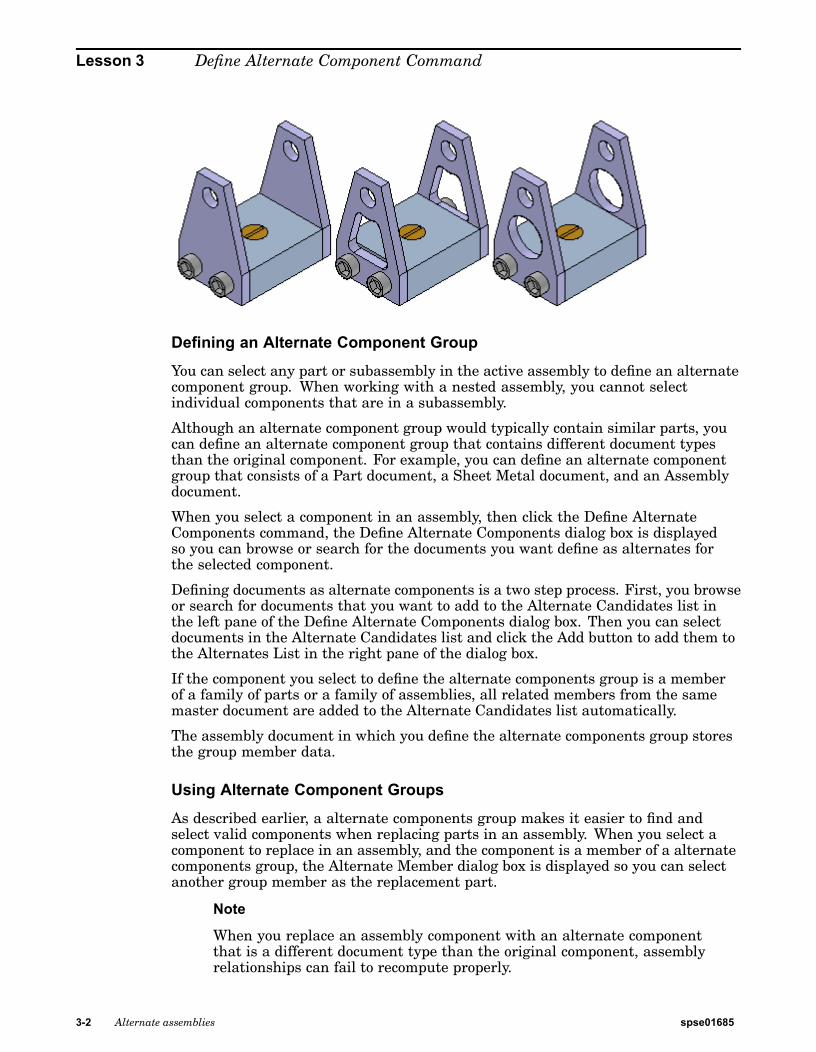
Defining an Alternate Component Group
You can select any part or subassembly in the active assembly to define an alternatecomponent group. When working with a nested assembly, you cannot selectindividual components that are in a subassembly.
Although an alternate component group would typically contain similar parts, youcan define an alternate component group that contains different document typesthan the original component. For example, you can define an alternate componentgroup that consists of a Part document, a Sheet Metal document, and an Assemblydocument.
When you select a component in an assembly, then click the Define AlternateComponents command, the Define Alternate Components dialog box is displayedso you can browse or search for the documents you want define as alternates forthe selected component.
Defining documents as alternate components is a two step process. First, you browseor search for documents that you want to add to the Alternate Candidates list inthe left pane of the Define Alternate Components dialog box. Then you can selectdocuments in the Alternate Candidates list and click the Add button to add them tothe Alternates List in the right pane of the dialog box.
If the component you select to define the alternate components group is a memberof a family of parts or a family of assemblies, all related members from the samemaster document are added to the Alternate Candidates list automatically.
The assembly document in which you define the alternate components group storesthe group member data.
Using Alternate Component Groups
As described earlier, a alternate components group makes it easier to find andselect valid components when replacing parts in an assembly. When you select acomponent to replace in an assembly, and the component is a member of a alternatecomponents group, the Alternate Member dialog box is displayed so you can selectanother group member as the replacement part.
Note
When you replace an assembly component with an alternate componentthat is a different document type than the original component, assemblyrelationships can fail to recompute properly.
3-2 Alternate assemblies spse01685
Define Alternate Component Command
If you want to replace the component with a component that is not an alternatecomponents member, you can click the Browse button to display the ReplacementPart dialog box to select another component.
If you create alternate component groups that are used frequently in manyassemblies, you should consider creating an assembly that contains only the masteralternate component and define the alternate components group in this document.This assembly document then becomes the master document for the alternatecomponents group definition.
To place one of the group members in an assembly later, you can place the assemblydocument instead. If you also set the Disperse This Assembly During Place Partoption on the Assembly tab of the Options dialog box for this assembly, when youplace the assembly into another assembly, it will be placed as a part that containsthe alternate components group data.
This workflow can be useful when you know a part will be replaced later by anotherpart. For example, you may create a prototype version of a part that you knowwill later be replaced by a production version of the part that will be createdindependently in a separate document.
Alternate Components and Alternate Assemblies
You can use an alternate component to replace a component in an alternate assemblythat is a family of assemblies, but not an alternate position assembly. For example,you can use the Replace command to replace a part in a family of assembly memberwith an alternate component, rather than use the Exclude Occurrence functionalityon the Alternate Assembly tab. Although this approach can be quicker than usingthe Exclude Occurrence functionality, when you use Revision Manager to copyor move the assembly data set to a new location, any members of the alternatecomponents group that are not used in a family of assembly member will not beincluded in the data set.
For more information on working with alternate assemblies, see the AlternateAssemblies Help topic.
Comparing Alternate Components and Family of Parts
Alternate Component groups are similar to a family of parts, but provideadditional flexibility because you can define an alternate components group usingindependently created documents and different document types.
spse01685 Alternate assemblies 3-3

Lesson
4 Activity: Creating an alternateassembly
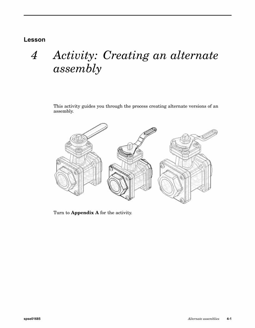
This activity guides you through the process creating alternate versions of anassembly.
Turn to Appendix A for the activity.
spse01685 Alternate assemblies 4-1

Lesson
5 Lesson review
Answer the following questions:
1. In the Alternate Assemblies tab in PathFinder, what two types of assembliescan you create?
2. In a family of assemblies, which substitutions, modifications or exclusions areallowed?
3. Can an assembly family member be saved as a unique assembly?
4. How do you place an assembly family member on a drawing sheet?
spse01685 Alternate assemblies 5-1

Answers
1. In the Alternate Assemblies tab in PathFinder, what two types of assembliescan you create?
In the Alternate Assemblies tab in PathFinder, you can create a family ofassemblies or an alternate assembly.
2. In a family of assemblies, which substitutions, modifications or exclusions areallowed?
The list of substitutions modifications and exclusions is:
• Offset values for assembly relationships
• Occurrence overrides
• Excluded occurrences
• Excluded relationships
• Excluded assembly features
• Excluded frames
• Excluded piping routes
• Excluded pattern occurrences
• Excluded fasteners
3. Can an assembly family member be saved as a unique assembly?
An assembly family member can be saved as a unique assembly.
4. How do you place an assembly family member on a drawing sheet?
When the drawing view wizard is run on the alternate assembly, the list offamily members is provided for selection of the correct member
spse01685 Alternate assemblies 0-1

Lesson
6 Lesson summary
In this lesson you learned how to create an alternate assembly. In the alternateassembly, you learned how to add new members, define unique variablesfor individual members, exclude member occurrences and reapply assemblyrelationships for a member.
spse01685 Alternate assemblies 6-1

A Activity: Creating an alternateassembly
Objectives
When you complete this activity, you will be able to:
• Convert a normal assembly into an alternate assembly.
• Add members to an alternate assembly.
• Define unique variable values for individual members.
• Replace occurrences for a member.
• Exclude occurrences for a member.
• Exclude and reapply assembly relationships for a member.
Create an alternate assembly for a valveCreate an alternate assembly for a valve. The valve in the existing assembly is open.Create an alternate assembly with the valve closed.
▸ Open Alternate.asm located in the folder where you loaded the parts files neededfor this activity. Open the assembly with all the parts active.
▸ On the View tab, click Color Manager, and ensure the following options are set.
▸ Set the use individual part styles option.
▸ Set the show and allow assembly style overrides option.
spse01685 Alternate assemblies A-1
A Activity: Creating an alternate assembly
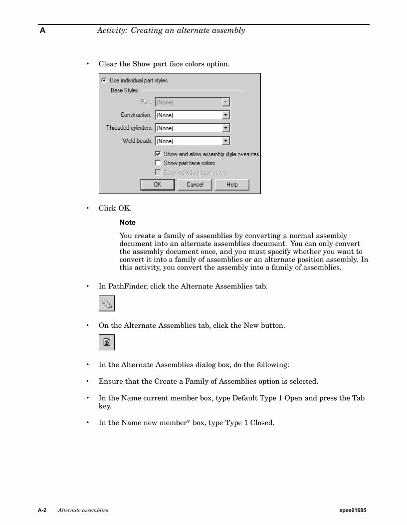
▸ Clear the Show part face colors option.
▸ Click OK.
Note
You create a family of assemblies by converting a normal assemblydocument into an alternate assemblies document. You can only convertthe assembly document once, and you must specify whether you want toconvert it into a family of assemblies or an alternate position assembly. Inthis activity, you convert the assembly into a family of assemblies.
▸ In PathFinder, click the Alternate Assemblies tab.
▸ On the Alternate Assemblies tab, click the New button.
▸ In the Alternate Assemblies dialog box, do the following:
▸ Ensure that the Create a Family of Assemblies option is selected.
▸ In the Name current member box, type Default Type 1 Open and press the Tabkey.
▸ In the Name new member* box, type Type 1 Closed.
A-2 Alternate assemblies spse01685
Activity: Creating an alternate assembly
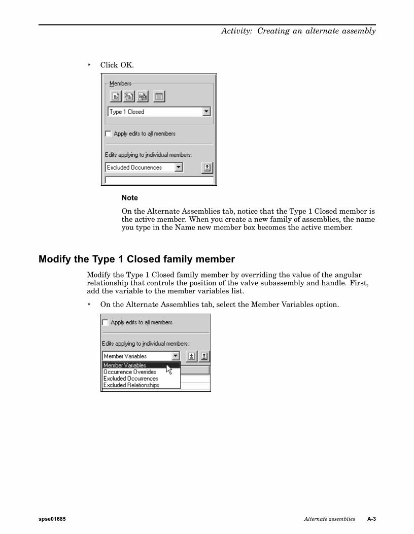
▸ Click OK.
Note
On the Alternate Assemblies tab, notice that the Type 1 Closed member isthe active member. When you create a new family of assemblies, the nameyou type in the Name new member box becomes the active member.
Modify the Type 1 Closed family memberModify the Type 1 Closed family member by overriding the value of the angularrelationship that controls the position of the valve subassembly and handle. First,add the variable to the member variables list.
▸ On the Alternate Assemblies tab, select the Member Variables option.
spse01685 Alternate assemblies A-3
A Activity: Creating an alternate assembly
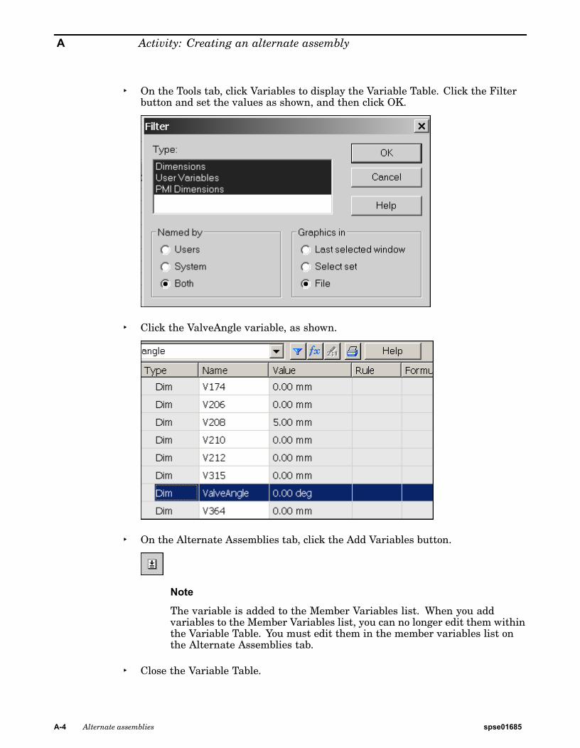
▸ On the Tools tab, click Variables to display the Variable Table. Click the Filterbutton and set the values as shown, and then click OK.
▸ Click the ValveAngle variable, as shown.
▸ On the Alternate Assemblies tab, click the Add Variables button.
Note
The variable is added to the Member Variables list. When you addvariables to the Member Variables list, you can no longer edit them withinthe Variable Table. You must edit them in the member variables list onthe Alternate Assemblies tab.
▸ Close the Variable Table.
A-4 Alternate assemblies spse01685
Activity: Creating an alternate assembly
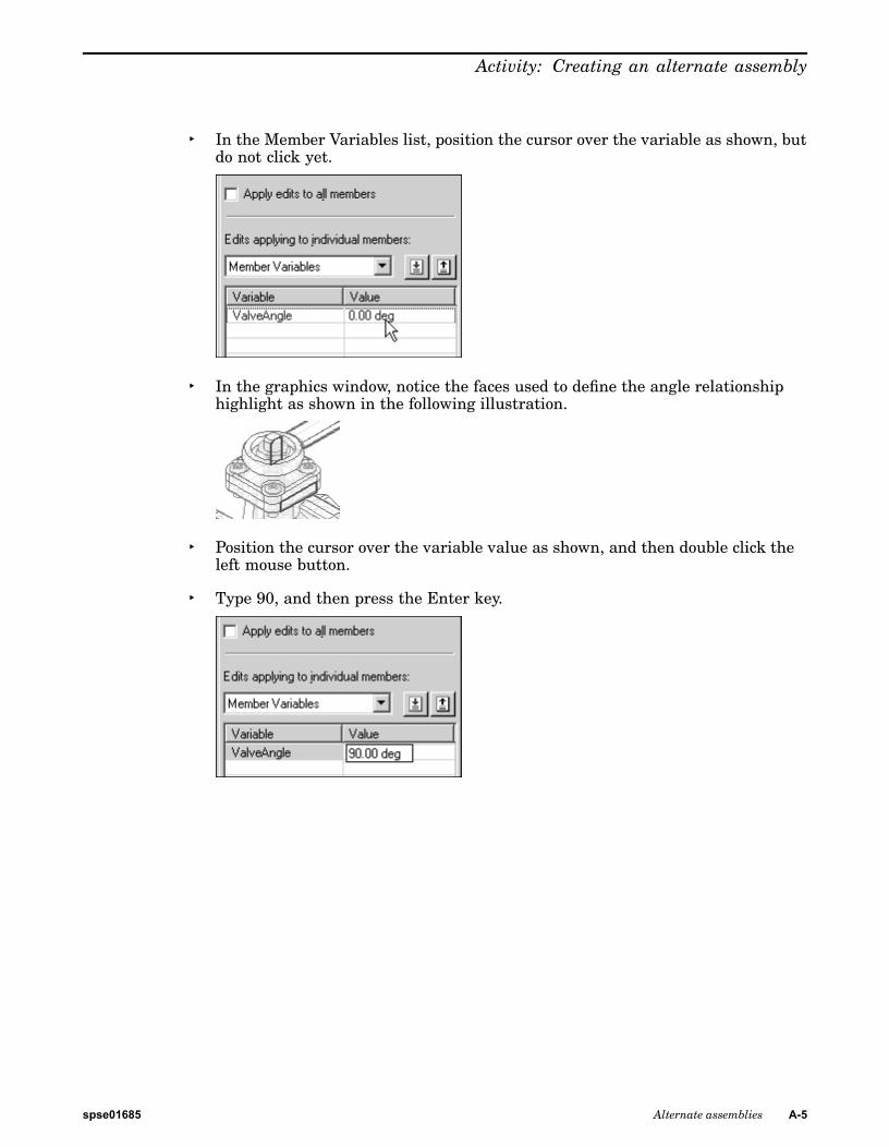
▸ In the Member Variables list, position the cursor over the variable as shown, butdo not click yet.
▸ In the graphics window, notice the faces used to define the angle relationshiphighlight as shown in the following illustration.
▸ Position the cursor over the variable value as shown, and then double click theleft mouse button.
▸ Type 90, and then press the Enter key.
spse01685 Alternate assemblies A-5
A Activity: Creating an alternate assembly
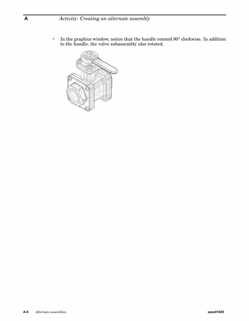
▸ In the graphics window, notice that the handle rotated 90° clockwise. In additionto the handle, the valve subassembly also rotated.
A-6 Alternate assemblies spse01685
Activity: Creating an alternate assembly
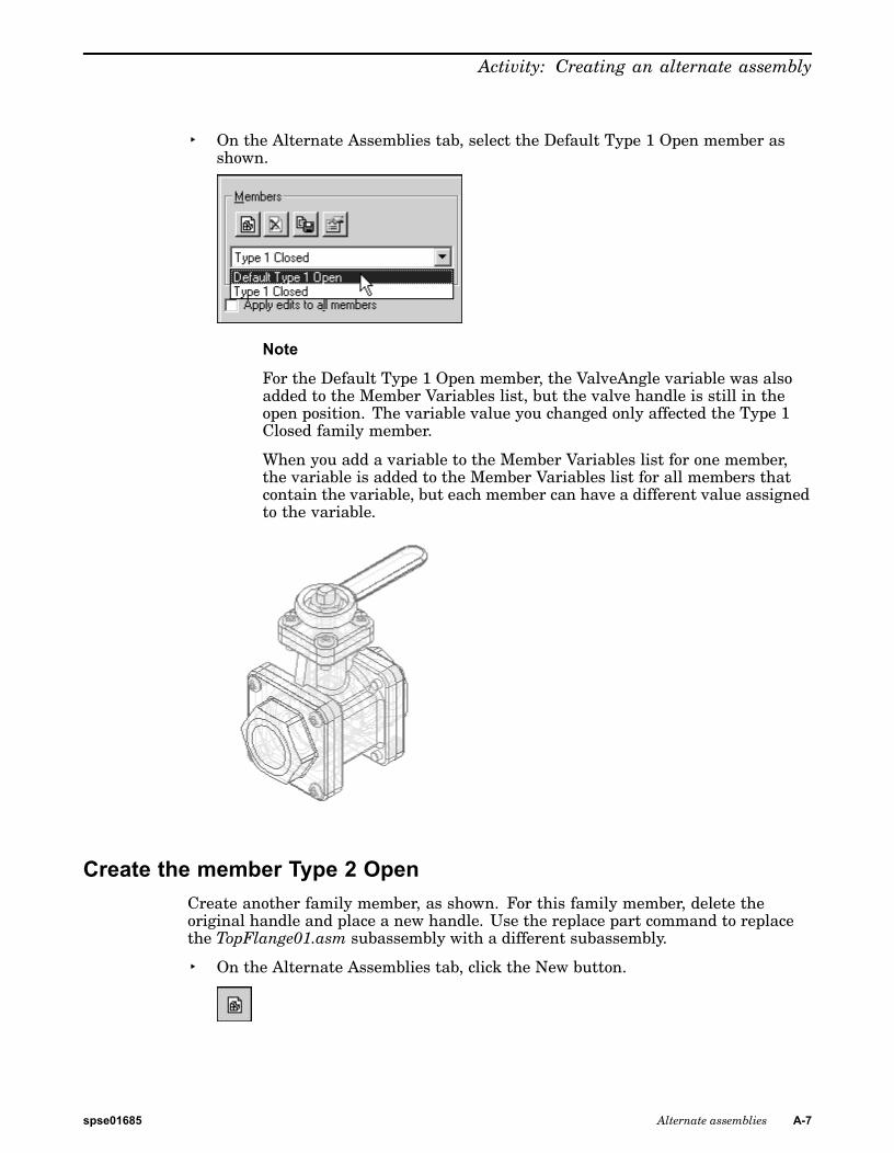
▸ On the Alternate Assemblies tab, select the Default Type 1 Open member asshown.
Note
For the Default Type 1 Open member, the ValveAngle variable was alsoadded to the Member Variables list, but the valve handle is still in theopen position. The variable value you changed only affected the Type 1Closed family member.
When you add a variable to the Member Variables list for one member,the variable is added to the Member Variables list for all members thatcontain the variable, but each member can have a different value assignedto the variable.
Create the member Type 2 OpenCreate another family member, as shown. For this family member, delete theoriginal handle and place a new handle. Use the replace part command to replacethe TopFlange01.asm subassembly with a different subassembly.
▸ On the Alternate Assemblies tab, click the New button.
spse01685 Alternate assemblies A-7
A Activity: Creating an alternate assembly
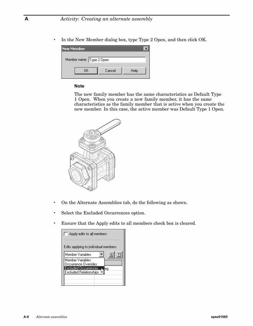
▸ In the New Member dialog box, type Type 2 Open, and then click OK.
Note
The new family member has the same characteristics as Default Type1 Open. When you create a new family member, it has the samecharacteristics as the family member that is active when you create thenew member. In this case, the active member was Default Type 1 Open.
▸ On the Alternate Assemblies tab, do the following as shown.
▸ Select the Excluded Occurrences option.
▸ Ensure that the Apply edits to all members check box is cleared.
A-8 Alternate assemblies spse01685
Activity: Creating an alternate assembly
Note
When you exclude occurrences, you can exclude them for all family membersor for only the active member. In this case, you want to exclude the handlefor only the active member.
When you exclude an occurrence for all family members, the occurrence isphysically deleted from the assembly file, and it is not added to the excludedoccurrences list.
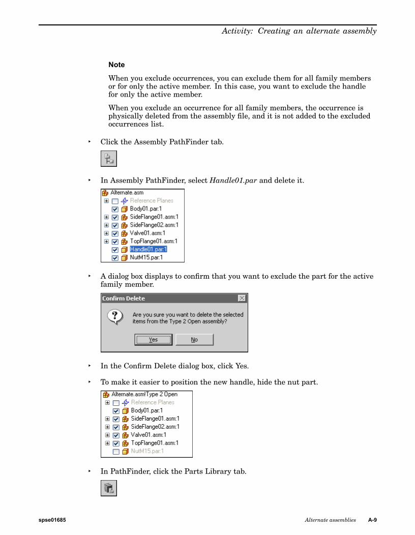
▸ Click the Assembly PathFinder tab.
▸ In Assembly PathFinder, select Handle01.par and delete it.
▸ A dialog box displays to confirm that you want to exclude the part for the activefamily member.
▸ In the Confirm Delete dialog box, click Yes.
▸ To make it easier to position the new handle, hide the nut part.
▸ In PathFinder, click the Parts Library tab.
spse01685 Alternate assemblies A-9
A Activity: Creating an alternate assembly
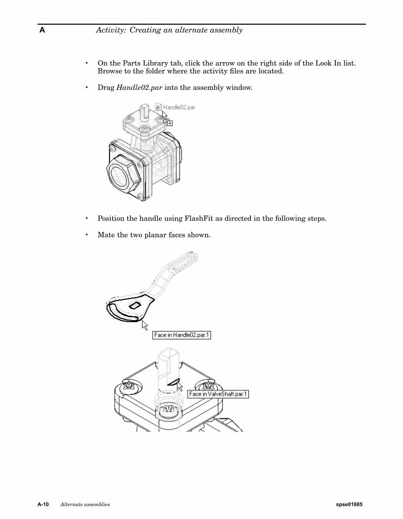
▸ On the Parts Library tab, click the arrow on the right side of the Look In list.Browse to the folder where the activity files are located.
▸ Drag Handle02.par into the assembly window.
▸ Position the handle using FlashFit as directed in the following steps.
▸ Mate the two planar faces shown.
A-10 Alternate assemblies spse01685
Activity: Creating an alternate assembly
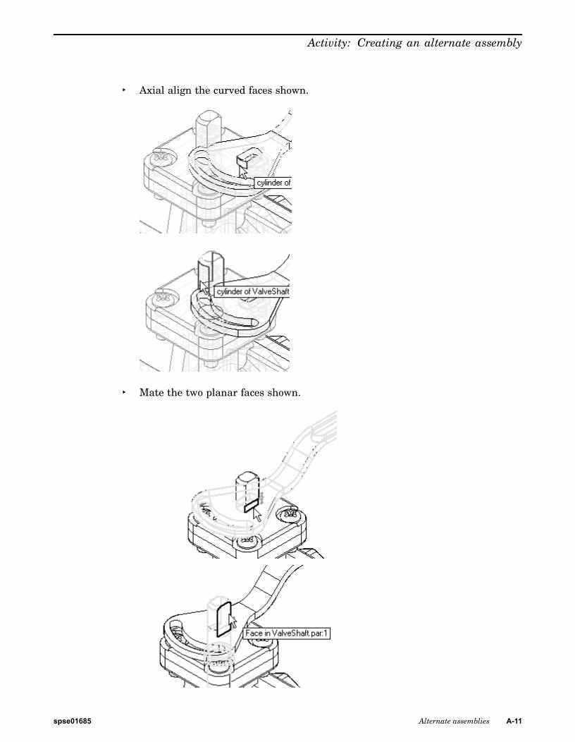
▸ Axial align the curved faces shown.
▸ Mate the two planar faces shown.
spse01685 Alternate assemblies A-11
A Activity: Creating an alternate assembly
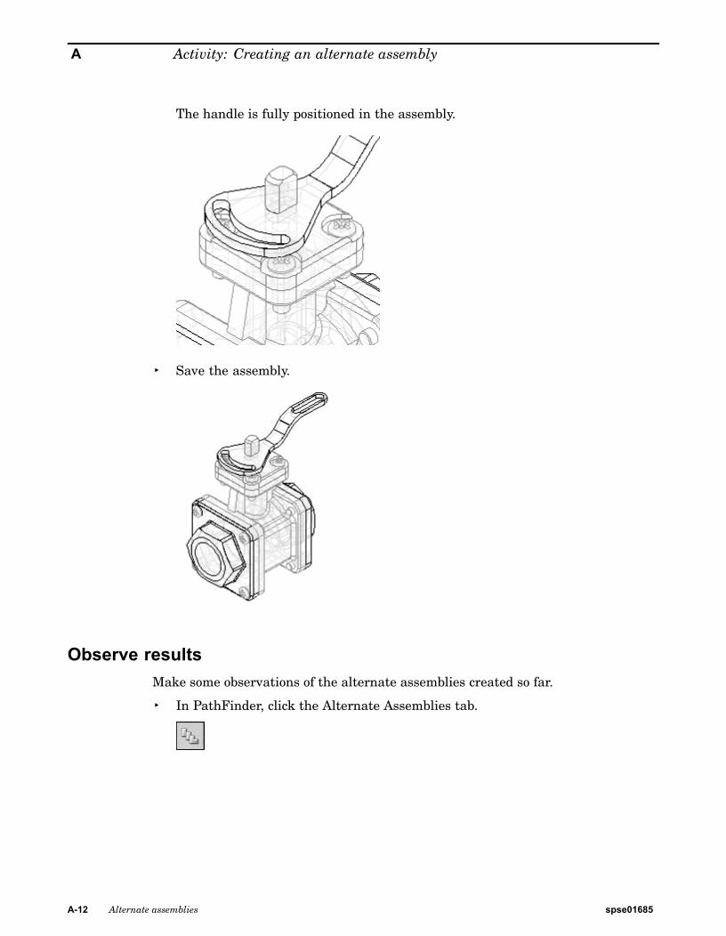
The handle is fully positioned in the assembly.
▸ Save the assembly.
Observe resultsMake some observations of the alternate assemblies created so far.
▸ In PathFinder, click the Alternate Assemblies tab.
A-12 Alternate assemblies spse01685
Activity: Creating an alternate assembly
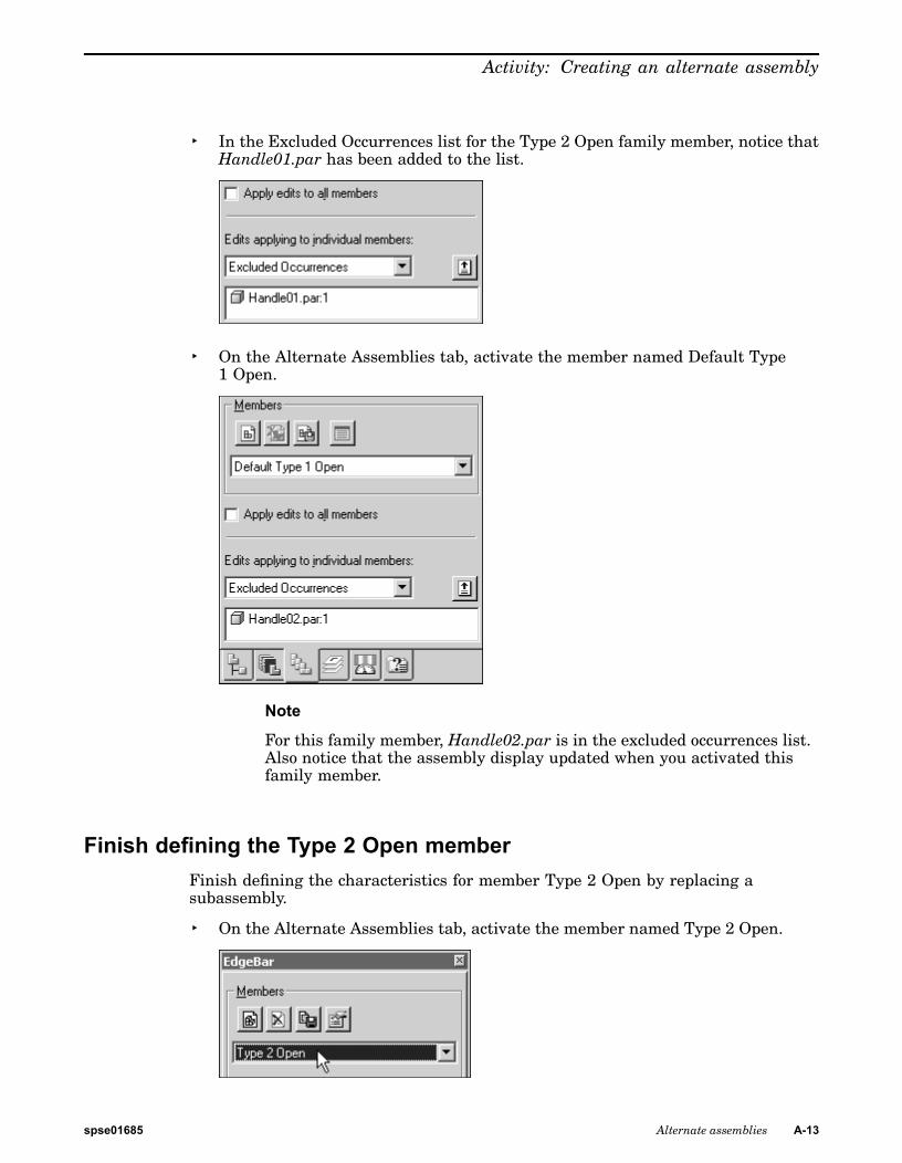
▸ In the Excluded Occurrences list for the Type 2 Open family member, notice thatHandle01.par has been added to the list.
▸ On the Alternate Assemblies tab, activate the member named Default Type1 Open.
Note
For this family member, Handle02.par is in the excluded occurrences list.Also notice that the assembly display updated when you activated thisfamily member.
Finish defining the Type 2 Open memberFinish defining the characteristics for member Type 2 Open by replacing asubassembly.
▸ On the Alternate Assemblies tab, activate the member named Type 2 Open.
spse01685 Alternate assemblies A-13
A Activity: Creating an alternate assembly
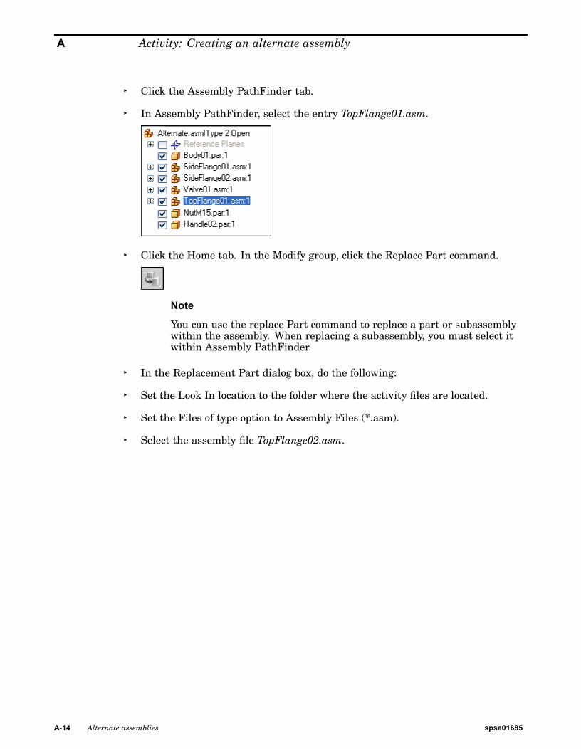
▸ Click the Assembly PathFinder tab.
▸ In Assembly PathFinder, select the entry TopFlange01.asm.
▸ Click the Home tab. In the Modify group, click the Replace Part command.
Note
You can use the replace Part command to replace a part or subassemblywithin the assembly. When replacing a subassembly, you must select itwithin Assembly PathFinder.
▸ In the Replacement Part dialog box, do the following:
▸ Set the Look In location to the folder where the activity files are located.
▸ Set the Files of type option to Assembly Files (*.asm).
▸ Select the assembly file TopFlange02.asm.
A-14 Alternate assemblies spse01685
Activity: Creating an alternate assembly
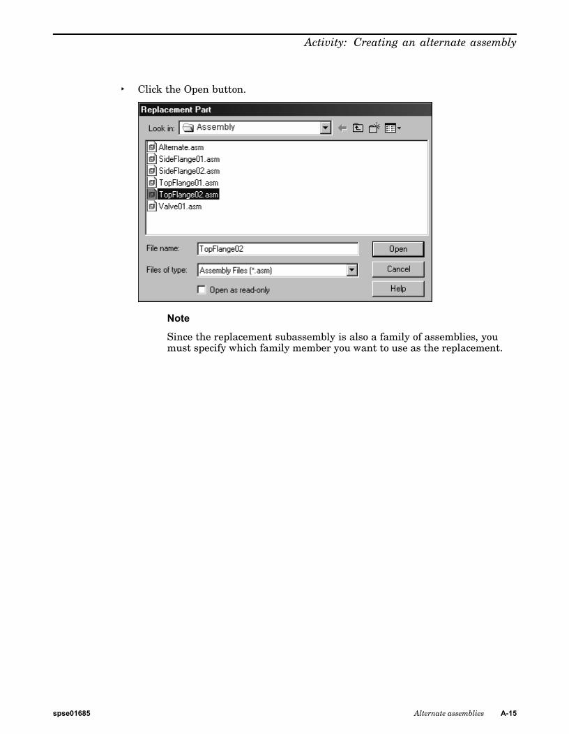
▸ Click the Open button.
Note
Since the replacement subassembly is also a family of assemblies, youmust specify which family member you want to use as the replacement.
spse01685 Alternate assemblies A-15
A Activity: Creating an alternate assembly
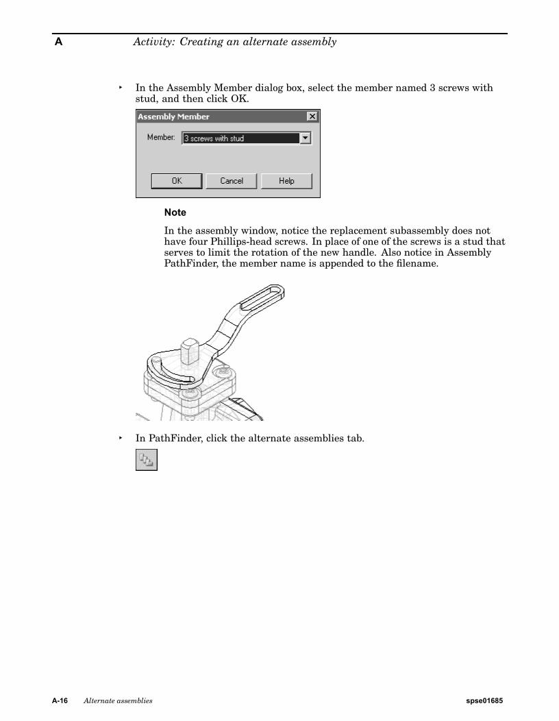
▸ In the Assembly Member dialog box, select the member named 3 screws withstud, and then click OK.
Note
In the assembly window, notice the replacement subassembly does nothave four Phillips-head screws. In place of one of the screws is a stud thatserves to limit the rotation of the new handle. Also notice in AssemblyPathFinder, the member name is appended to the filename.
▸ In PathFinder, click the alternate assemblies tab.
A-16 Alternate assemblies spse01685
Activity: Creating an alternate assembly
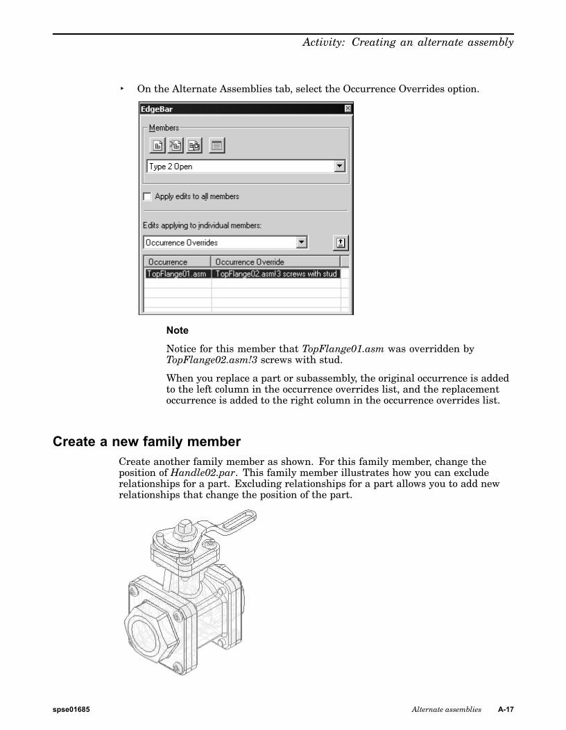
▸ On the Alternate Assemblies tab, select the Occurrence Overrides option.
Note
Notice for this member that TopFlange01.asm was overridden byTopFlange02.asm!3 screws with stud.
When you replace a part or subassembly, the original occurrence is addedto the left column in the occurrence overrides list, and the replacementoccurrence is added to the right column in the occurrence overrides list.
Create a new family memberCreate another family member as shown. For this family member, change theposition of Handle02.par. This family member illustrates how you can excluderelationships for a part. Excluding relationships for a part allows you to add newrelationships that change the position of the part.
spse01685 Alternate assemblies A-17
A Activity: Creating an alternate assembly
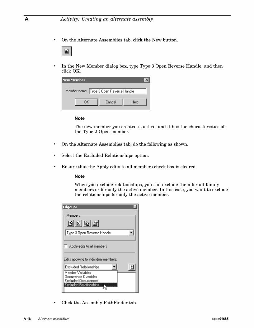
▸ On the Alternate Assemblies tab, click the New button.
▸ In the New Member dialog box, type Type 3 Open Reverse Handle, and thenclick OK.
Note
The new member you created is active, and it has the characteristics ofthe Type 2 Open member.
▸ On the Alternate Assemblies tab, do the following as shown.
▸ Select the Excluded Relationships option.
▸ Ensure that the Apply edits to all members check box is cleared.
Note
When you exclude relationships, you can exclude them for all familymembers or for only the active member. In this case, you want to excludethe relationships for only the active member.
▸ Click the Assembly PathFinder tab.
A-18 Alternate assemblies spse01685
Activity: Creating an alternate assembly
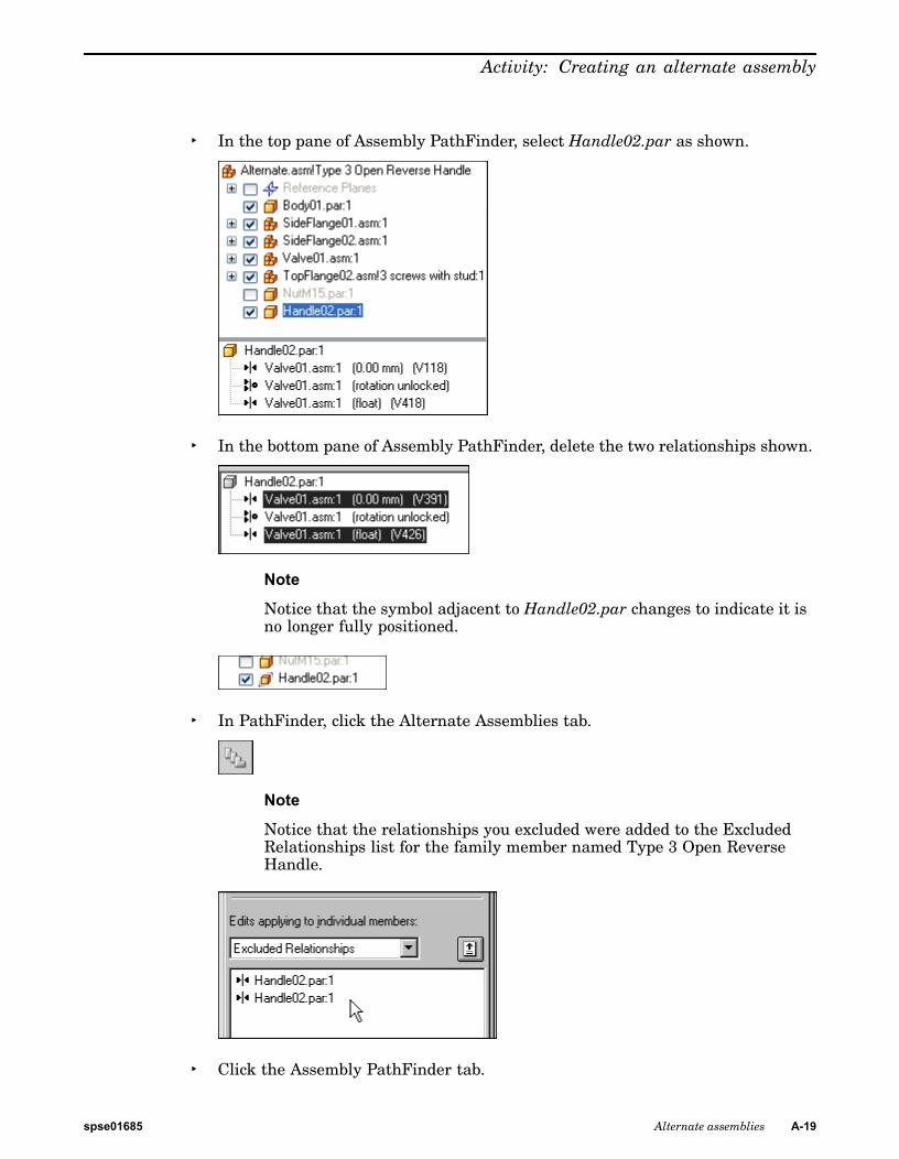
▸ In the top pane of Assembly PathFinder, select Handle02.par as shown.
▸ In the bottom pane of Assembly PathFinder, delete the two relationships shown.
Note
Notice that the symbol adjacent to Handle02.par changes to indicate it isno longer fully positioned.
▸ In PathFinder, click the Alternate Assemblies tab.
Note
Notice that the relationships you excluded were added to the ExcludedRelationships list for the family member named Type 3 Open ReverseHandle.
▸ Click the Assembly PathFinder tab.
spse01685 Alternate assemblies A-19
A Activity: Creating an alternate assembly
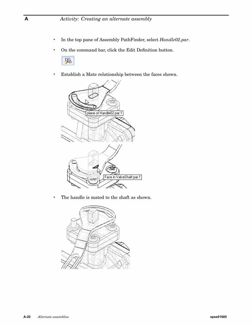
▸ In the top pane of Assembly PathFinder, select Handle02.par.
▸ On the command bar, click the Edit Definition button.
▸ Establish a Mate relationship between the faces shown.
▸ The handle is mated to the shaft as shown.
A-20 Alternate assemblies spse01685
Activity: Creating an alternate assembly
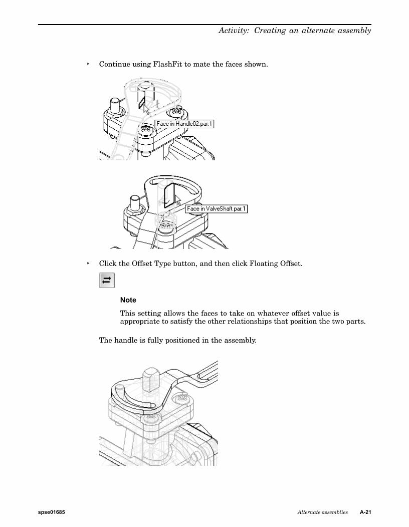
▸ Continue using FlashFit to mate the faces shown.
▸ Click the Offset Type button, and then click Floating Offset.
Note
This setting allows the faces to take on whatever offset value isappropriate to satisfy the other relationships that position the two parts.
The handle is fully positioned in the assembly.
spse01685 Alternate assemblies A-21
A Activity: Creating an alternate assembly
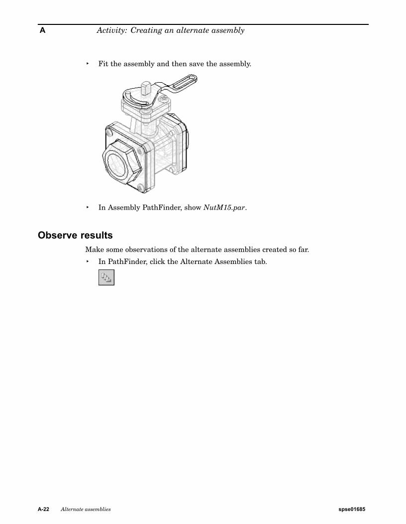
▸ Fit the assembly and then save the assembly.
▸ In Assembly PathFinder, show NutM15.par.
Observe resultsMake some observations of the alternate assemblies created so far.
▸ In PathFinder, click the Alternate Assemblies tab.
A-22 Alternate assemblies spse01685
Activity: Creating an alternate assembly
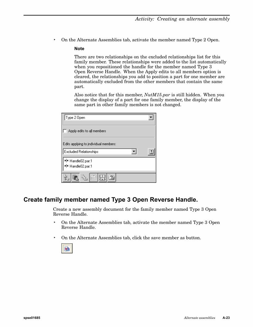
▸ On the Alternate Assemblies tab, activate the member named Type 2 Open.
Note
There are two relationships on the excluded relationships list for thisfamily member. These relationships were added to the list automaticallywhen you repositioned the handle for the member named Type 3Open Reverse Handle. When the Apply edits to all members option iscleared, the relationships you add to position a part for one member areautomatically excluded from the other members that contain the samepart.
Also notice that for this member, NutM15.par is still hidden. When youchange the display of a part for one family member, the display of thesame part in other family members is not changed.
Create family member named Type 3 Open Reverse Handle.Create a new assembly document for the family member named Type 3 OpenReverse Handle.
▸ On the Alternate Assemblies tab, activate the member named Type 3 OpenReverse Handle.
▸ On the Alternate Assemblies tab, click the save member as button.
spse01685 Alternate assemblies A-23
A Activity: Creating an alternate assembly
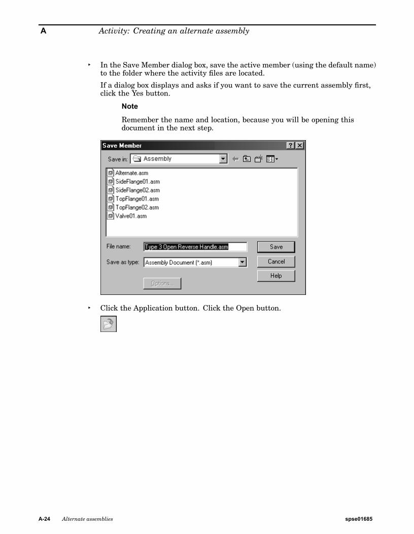
▸ In the Save Member dialog box, save the active member (using the default name)to the folder where the activity files are located.
If a dialog box displays and asks if you want to save the current assembly first,click the Yes button.
Note
Remember the name and location, because you will be opening thisdocument in the next step.
▸ Click the Application button. Click the Open button.
A-24 Alternate assemblies spse01685
Activity: Creating an alternate assembly
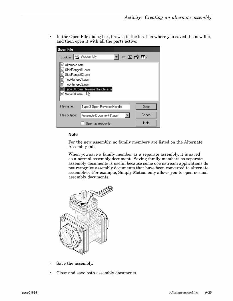
▸ In the Open File dialog box, browse to the location where you saved the new file,and then open it with all the parts active.
Note
For the new assembly, no family members are listed on the AlternateAssembly tab.
When you save a family member as a separate assembly, it is savedas a normal assembly document. Saving family members as separateassembly documents is useful because some downstream applications donot recognize assembly documents that have been converted to alternateassemblies. For example, Simply Motion only allows you to open normalassembly documents.
▸ Save the assembly.
▸ Close and save both assembly documents.
spse01685 Alternate assemblies A-25
A Activity: Creating an alternate assembly
Draft family of assembly membersCreate a new draft document and place a drawing view of one of the family ofassembly members.
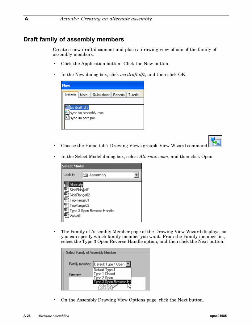
▸ Click the Application button. Click the New button.
▸ In the New dialog box, click iso draft.dft, and then click OK.
▸ Choose the Home tab®Drawing Views group®View Wizard command .
▸ In the Select Model dialog box, select Alternate.asm, and then click Open.
▸ The Family of Assembly Member page of the Drawing View Wizard displays, soyou can specify which family member you want. From the Family member list,select the Type 3 Open Reverse Handle option, and then click the Next button.
▸ On the Assembly Drawing View Options page, click the Next button.
A-26 Alternate assemblies spse01685
Activity: Creating an alternate assembly
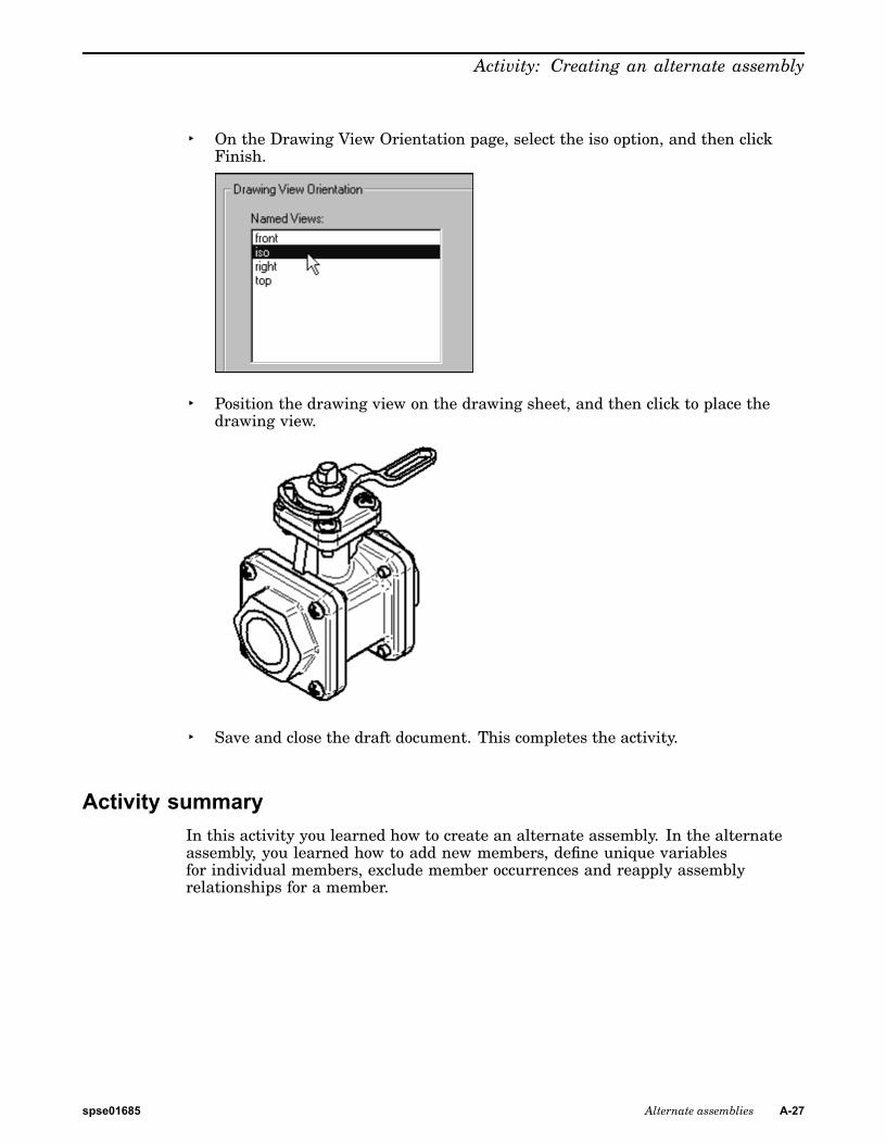
▸ On the Drawing View Orientation page, select the iso option, and then clickFinish.
▸ Position the drawing view on the drawing sheet, and then click to place thedrawing view.
▸ Save and close the draft document. This completes the activity.
Activity summaryIn this activity you learned how to create an alternate assembly. In the alternateassembly, you learned how to add new members, define unique variablesfor individual members, exclude member occurrences and reapply assemblyrelationships for a member.
spse01685 Alternate assemblies A-27