alternate names: rock wall, gravity wall, toe wall, … 4/4... · advantages prevents slope ......
TRANSCRIPT
TRPA BMP Handbook Chapter 4: BMP Toolkit May 2014 4.2-f Retaining Wall Page 31
4.2-f RETAINING WALL
Alternate Names: Rock Wall, Gravity Wall, Toe Wall, Gabion Wall, Timber Wall
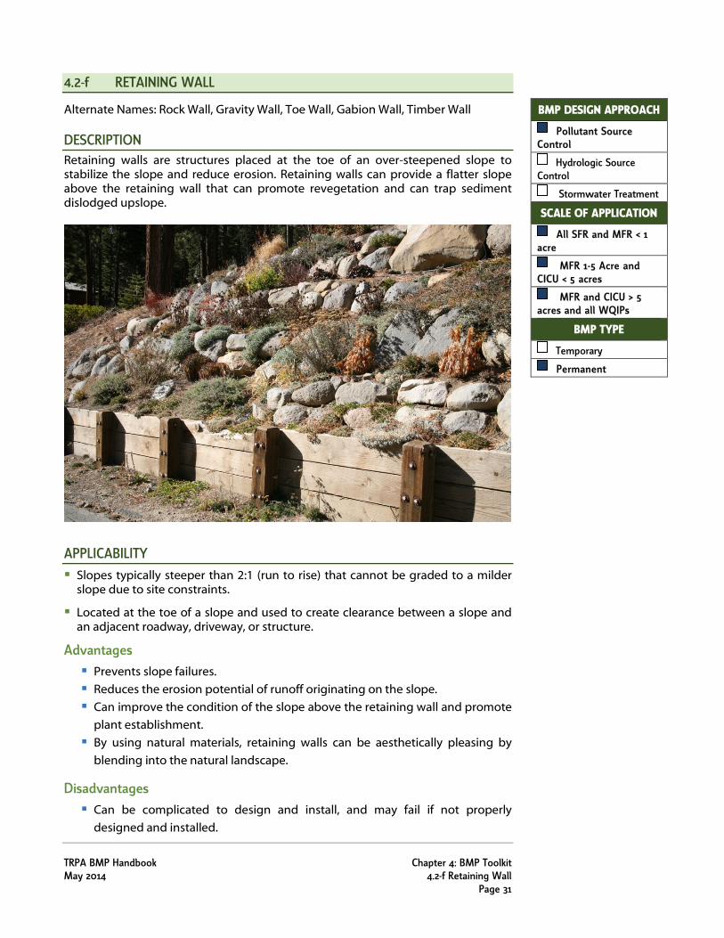
DESCRIPTION Retaining walls are structures placed at the toe of an over-steepened slope to stabilize the slope and reduce erosion. Retaining walls can provide a flatter slope above the retaining wall that can promote revegetation and can trap sediment dislodged upslope.
APPLICABILITY Slopes typically steeper than 2:1 (run to rise) that cannot be graded to a milder
slope due to site constraints.
Located at the toe of a slope and used to create clearance between a slope and an adjacent roadway, driveway, or structure.
Advantages Prevents slope failures.
Reduces the erosion potential of runoff originating on the slope.
Can improve the condition of the slope above the retaining wall and promote
plant establishment.
By using natural materials, retaining walls can be aesthetically pleasing by
blending into the natural landscape.
Disadvantages Can be complicated to design and install, and may fail if not properly
designed and installed.
BMP DESIGN APPROACH
Pollutant Source Control
Hydrologic Source Control
Stormwater Treatment
SCALE OF APPLICATION
All SFR and MFR < 1 acre
MFR 1-5 Acre and CICU < 5 acres
MFR and CICU > 5 acres and all WQIPs
BMP TYPE
Temporary
Permanent

Chapter 4: BMP Toolkit TRPA BMP Handbook 4.2-f Retaining Wall May 2014 Page 32
Can be damaged by snow removal equipment when located adjacent to
streets and highways.
DESIGN CONSIDERATIONS For complicated applications, consult with a licensed professional civil engineer when designing any retaining wall for a steep slope. For simple applications with retaining walls less than 3 feet in height, the following design considerations may be applicable:
Design walls with adequate drainage immediately behind the wall. This is typically accomplished by placing porous backfill or drain rock behind the wall with a perforated underdrain at the base of the porous backfill.
Design retaining walls to extend slightly above the fill compacted behind the wall (typically 6 inches is sufficient). This approach allows the retaining wall to trap sediment that may be dislodged upslope, and reduces sloughing of sediment over the top of the wall.
Install retaining walls on firm foundation of compacted soil.
When constructing a retaining wall adjacent to a paved surface, install a stabilized conveyance at the toe of the wall adjacent to the paved surface to avoid the potential for runoff to undercut the wall.
Ensure that the color of retaining walls is compatible with the surroundings. Select colors from the Munsell® colors set forth in Appendix G, TRPA Approved Range of Earthtone Colors, of the TRPA Design Review Guidelines.
Retaining structures can be built from a variety of materials, both natural and artificial. Retaining walls discussed in the Handbook are classified into the following categories:
Gravity Wall: Gravity walls rely on the mass or weight of their structure to resist lateral earth forces to stabilize a slope. Gravity walls can be made of concrete or masonry, prefabricated interlocking concrete units, or rock. Rock walls are the preferred type of gravity wall in the Lake Tahoe Region because rock can be selected to blend with the natural environment better than concrete or masonry options.
ROCK WALL: Rock walls are typically built from rock 1.5 feet to 3 feet in diameter and are
typically no more than 3 feet in height.
Rock walls are not intended to resist large lateral earth pressures, and
behave more like a revetment than a retaining wall.
Rock walls are porous and provide interstitial spaces that can be planted.
GABION WALL: Gabion walls consist of a wire mesh box filled with rock and wired together
to form a retaining wall.
Low gabion walls are a comparable alternative to rock walls when large
rock is not available. However, gabion walls are considered the least
aesthetic option among the retaining walls described in this Handbook.

TRPA BMP Handbook Chapter 4: BMP Toolkit May 2014 4.2-f Retaining Wall Page 33
Advantages of gabions include their ability to be stacked in various
shapes, accommodate ground movement, dissipate energy of flowing
water, and drain freely.
Timber Wall: Timber walls are typically built using wood planking and posts. A firm
foundation is necessary to securely anchor the wall. When the foundation for
the wall is less than optimal, longer posts with deeper concrete footings and
closer spacing may be considered.
Lumber, timber, and posts should be treated with an EPA approved wood
preservative.
The alignment of a wood wall needs to be straighter than that required for a
rock wall. Some rough grading may be required to provide an adequate
alignment.
Timber walls typically have a shorter life-span relative to the gravity walls
described in this Handbook and may require more maintenance.
INSTALLATION CONSIDERATIONS
Rock Wall: Remove all large rocks from the slope face and stockpile on site.
Excavate a footing trench along the toe of the slope, and stockpile material
for fill behind the rocks.
Place the largest rocks in the footing trench with their longitudinal axis into
the slope face.
Arrange rocks so that each rock has at least a three-point bearing on the
footing trench or the underlying rocks. Place rocks so that their centers of
gravity are as low as possible.
As the rocks are placed, add fill material around and behind the rocks and
tamp it thoroughly.
Configure the rock wall so that the external face is inclined slightly into the
slope (battered) using a 6:1 (rise to run) batter angle. Battering shifts the
center of gravity away from the toe and into the slope, and increases
resistance to overturning.
Revegetate the backfilled bench and slope behind the wall as soon as
possible.
Gabion Wall: Remove all large obstacles from the slope face.
Excavate a footing trench along the toe of the slope and stockpile material for
fill behind the rocks.
Place the empty gabions into position and wire them together.
Fill the baskets to one-third of their depth with 4 to 8 inch rock or stone. This
size of material is preferred because it is easily handled by equipment and
Chapter 4: BMP Toolkit TRPA BMP Handbook 4.2-f Retaining Wall May 2014 Page 34
produces rather small voids when dumped into the empty baskets. The rock
material should have a minimum specific gravity of 2.5.
Tie in the connecting wires which brace opposing walls together. The
connecting wires prevent the baskets from bulging as they are filled.
Repeat this operation until the basket is filled and then secure the top with
wires to the ends, sides, and middle diaphragms.
Backfill and compact the slope behind the wall.
Revegetate the backfilled bench and slope behind the wall as soon as
possible.
Timber Wall: For a 3-foot high retaining wall, posts (6 inch x 6 inch) are typically 5 feet long
and 2 feet deep into concrete footings. Posts are typically set on 5-foot
centers.
After the concrete has set, install planking (3 inch x 12 inch or 2 inch x 12 inch)
on the upslope side of the posts.
Leave space at the base of the wall and between planks to allow drainage.
Use galvanized or zinc-coated steel bolts and washers to secure planking to
posts.
Backfill behind the wall with soil from excavations or soil from the slope
above. Compact the backfill behind the wall.
Revegetate the backfilled bench and slope behind the wall as soon as
possible.
INSPECTION AND MAINTENANCE Refer to Retaining Wall Inspection and Maintenance Table.
EFFECTIVENESS CONSIDERATIONS Retaining walls can be highly effective at preventing soil erosion from steep slopes. When properly installed, retaining walls can be effective for long periods of time while requiring minimal maintenance. Among steep slope stabilization practices, a retaining wall can be an aesthetic option because it can promote successful vegetation establishment on slopes behind the wall.

TRPA BMP Handbook Chapter 4: BMP Toolkit May 2014 4.2-f Retaining Wall Page 35
Retaining Wall Inspection and Maintenance Table
INSPECTION AND MAINTENANCE ACTIVITIES SUGGESTED FREQUENCY
INSPECTION EQUIPMENT
MAINTENANCE EQUIPMENT
Inspect for trash and unwanted debris. Remove trash and unwanted debris from the area.
Annually Trash bag
Inspect for invasive weeds10. Remove invasive weeds monthly during the first two growing seasons. Thereafter, weed annually, or as
needed.
Monthly during first growing season and annually thereafter
Invasive Weeds Inspector
Tools as needed to control infestation
Inspect for soil erosion and accumulation, especially on the slope and overtopping the wall. Remove accumulated sediment and dispose of sediment at stable on-site location or out of the Lake Tahoe
Region. Restore proper freeboard as indicated on engineered plans, or determine an appropriate amount per site
conditions. Seed, mulch, and irrigate eroded areas as necessary to establish vegetation and stabilize area.
Annually and after major storms
Shovel, Topsoil, Seed/Plants, Mulch, Irrigation
Inspect the underdrain system or porous backfill behind the retaining wall and ensure its functioning properly. It may be necessary to observe the function of an underdrain system during a rain event. If the underdrain system appears clogged, flush the system.
Annually Tools as needed
Inspect for bulging or leaning in the wall which are warning signs of a structurally unsound wall. Look for any broken or cracked timbers or dislodged rocks. Repair or replace unsafe and structurally unsound retaining walls. Relieve pressure on wall by ensuring proper drainage behind the wall (see above).
Annually
Tools as needed to repair wall (wood, concrete, blocks, etc.)
Inspect site for unusual or unsafe conditions (snowplow damage, structural damage, graffiti, tree growth, etc.). Repair walls as necessary.
Annually Tools as needed
Inspect for animal burrows, holes, and mounds. If burrows are causing erosion or compromising structural integrity, backfill firmly.
Annually Tools as needed to repair
10 Lake Tahoe Basin Weed Coordinating Group. http://www.tahoeinvasiveweeds.org/.

Chapter 4: BMP Toolkit TRPA BMP Handbook 4.2-f Retaining Wall May 2014 Page 36
Timber Retaining Wall Figure
THE TAHOE REGIONAL PLANNING AGENCY (TRPA) SHALL NOT BE RESPONSIBLE FOR THE ACCURACY OR COMPLETENESS OF ELECTRONIC COPIES OF THIS DETAIL.

TRPA BMP Handbook Chapter 4: BMP Toolkit May 2014 4.2-f Retaining Wall Page 37
Stacked Rock Wall Figure
THE TAHOE REGIONAL PLANNING AGENCY (TRPA) SHALL NOT BE RESPONSIBLE FOR THE ACCURACY OR COMPLETENESS OF ELECTRONIC COPIES OF THIS DETAIL.

Chapter 4: BMP Toolkit TRPA BMP Handbook 4.2-f Retaining Wall May 2014 Page 38