all-surface induction heating with high efficiency and
TRANSCRIPT

IEEE TRANSACTIONS ON CONSUMER ELECTRONICS, VOL. 64, NO. 3, AUGUST 2018 339
All-Surface Induction Heating With HighEfficiency and Space Invariance Enabled byArraying Squircle Coils in Square Lattice
Veli Tayfun Kilic , Member, IEEE, Emre Unal, Namik Yilmaz, and Hilmi Volkan Demir, Senior Member, IEEE
Abstract—This paper reports an all-surface induction heatingsystem that enables efficient heating at a constant speed all overthe surface independent of the specific location on the surface. Inthe proposed induction system, squircle coils are placed tangen-tially in a two-dimensional square lattice as opposed to commonlyused hexagonal packing. As a proof-of-concept demonstration,a simple model setup was constructed using a 3×3 coil arrayalong with a steel plate to be inductively heated. To model surfaceheating, a set of six locations for the plate was designated consid-ering symmetry points. For all of these cases, power dissipatedby the system and the plate’s transient heating were recorded.Independent from the specific plate position, almost equal heat-ing speeds were measured for the similar levels of dissipatedenergies in the system. Using full three-dimensional electromag-netic solutions, the experimental results were also verified. Thefindings indicate that the proposed system is proved to enableenergy efficient space-invariant heating in all-surface inductionhobs.
Index Terms—Coils, electromagnetic induction, energy effi-ciency, inductive power transmission.
I. INTRODUCTION
ALTHOUGH induction theory of M. Faraday goes backto the 19th century [1], its application to consumer elec-
tronics such as induction heating [2] and wireless chargingsystems [3]–[6] is relatively recent, which have been becom-ing increasingly more popular. Today domestic heating is
Manuscript received April 4, 2018; revised June 28, 2018; acceptedJuly 19, 2018. Date of publication July 25, 2018; date of current ver-sion September 24, 2018. This work was supported in part by ArcelikA.S. and in part by Industry Theses Program SAN-TEZ 1463-STZ-2012-2.(Corresponding author: Veli Tayfun Kilic.)
V. T. Kilic was with the Department of Electrical and ElectronicsEngineering, Bilkent University, 06800 Ankara, Turkey. He is now withthe Department of Electrical and Electronics Engineering, Abdullah GülUniversity, 38080 Kayseri, Turkey (e-mail: [email protected]).
E. Unal is with the Institute of Materials Science and Nanotechnology,Bilkent University, 06800 Ankara, Turkey (e-mail: [email protected]).
N. Yilmaz is with Power Electronics Department, ArçelikCompany (Arcelik Tuzla Campus), 34950 Istanbul, Turkey (e-mail:[email protected]).
H. V. Demir is with the Department of Electrical and ElectronicsEngineering, Bilkent University, 06800 Ankara, Turkey, also with theDepartment of Physics, Bilkent University, 06800 Ankara, Turkey, also withthe Institute of Materials Science and Nanotechnology, Bilkent University,06800 Ankara, Turkey, also with the School of Electrical and ElectronicEngineering, Nanyang Technological University, Singapore, and also withthe School of Physical and Mathematical Sciences, Nanyang TechnologicalUniversity, Singapore (e-mail: [email protected]).
Color versions of one or more of the figures in this paper are availableonline at http://ieeexplore.ieee.org.
Digital Object Identifier 10.1109/TCE.2018.2859627
one important application area where induction systems arewidely used. Because of its safety, cleanliness, controlledand quick warming capability, and high efficiency proper-ties, induction hobs are commonly used in the developedcountries [7], [8]. Conventional induction heaters typically uselarge coils mounted beneath the surface. However, for efficientheating, vessels should have sizes and shapes similar to thoseof the coils and they should be placed right on top of the coils.To overcome this issue and provide user flexibility, all-surfaceinduction heating has been introduced.
In all-surface induction hobs, an array of small coils isused. Working principle of all-surface induction relies ondetecting a vessel and powering only the corresponding coilsloaded by the vessel. For driving these coils in an efficientway, different control topologies have been reported [9]–[11].However, most of these all-surface designs [12], [13] employarrays of the conventional circular coils. Coils with differ-ent shapes including square and rectangular coils have alsobeen considered for all-surface induction heating [14]. Aswas demonstrated previously [15], interaction between coilshaving rounded shapes is not as strong as that betweensquare or rectangular coils. Although such strong interactionbetween side-by-side placed coils is highly desired for efficientall-surface heating, destructive coupling between diagonallylocated coils is undesired. Therefore, in most of the systemscoils are stacked densely regardless of uniform heating allover the surface. As a result, heating with high efficiencyand space invariance, which is not dependent on vessel posi-tion in the all-surface induction hob, is still an unresolvedproblem today.
In the previous literature, to the best of our knowledge,there have been no reports investigating the induction heat-ing of a load placed at various locations on a hob surface.Although there is a study about flexible cooking zone [16], theproposed method is not feasible for all-surface induction heat-ing because in the study mobile coils are offered for uniformheating of different loads. In addition, in another study [17]a method is introduced to manage heat distribution in zone-control induction heating. However, the proposed method isused for controlling power inverters of concentric coils, thusit is again not useful for all-surface induction hobs. To this end,in this paper we systematically studied an all-surface induc-tion heating system and comparatively measured the heatingefficiency and speed of the system for all possible loadingpositions. With our proposed system design, space-invariant
1558-4127 c© 2018 IEEE. Personal use is permitted, but republication/redistribution requires IEEE permission.See http://www.ieee.org/publications_standards/publications/rights/index.html for more information.
340 IEEE TRANSACTIONS ON CONSUMER ELECTRONICS, VOL. 64, NO. 3, AUGUST 2018
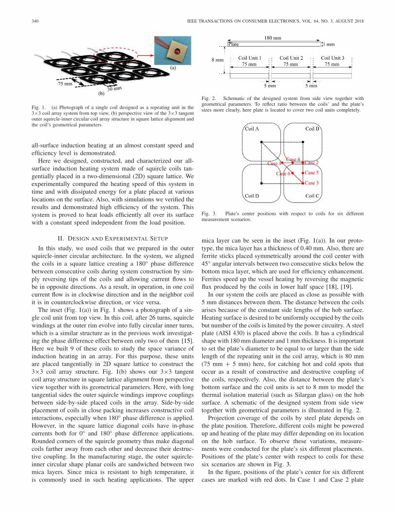
Fig. 1. (a) Photograph of a single coil designed as a repeating unit in the3×3 coil array system from top view, (b) perspective view of the 3×3 tangentouter squircle-inner circular coil array structure in square lattice alignment andthe coil’s geometrical parameters.
all-surface induction heating at an almost constant speed andefficiency level is demonstrated.
Here we designed, constructed, and characterized our all-surface induction heating system made of squircle coils tan-gentially placed in a two-dimensional (2D) square lattice. Weexperimentally compared the heating speed of this system intime and with dissipated energy for a plate placed at variouslocations on the surface. Also, with simulations we verified theresults and demonstrated high efficiency of the system. Thissystem is proved to heat loads efficiently all over its surfacewith a constant speed independent from the load position.
II. DESIGN AND EXPERIMENTAL SETUP
In this study, we used coils that we prepared in the outersquircle-inner circular architecture. In the system, we alignedthe coils in a square lattice creating a 180◦ phase differencebetween consecutive coils during system construction by sim-ply reversing tips of the coils and allowing current flows tobe in opposite directions. As a result, in operation, in one coilcurrent flow is in clockwise direction and in the neighbor coilit is in counterclockwise direction, or vice versa.
The inset (Fig. 1(a)) in Fig. 1 shows a photograph of a sin-gle coil unit from top view. In this coil, after 26 turns, squirclewindings at the outer rim evolve into fully circular inner turns,which is a similar structure as in the previous work investigat-ing the phase difference effect between only two of them [15].Here we built 9 of these coils to study the space variance ofinduction heating in an array. For this purpose, these unitsare placed tangentially in 2D square lattice to construct the3×3 coil array structure. Fig. 1(b) shows our 3×3 tangentcoil array structure in square lattice alignment from perspectiveview together with its geometrical parameters. Here, with longtangential sides the outer squircle windings improve couplingsbetween side-by-side placed coils in the array. Side-by-sideplacement of coils in close packing increases constructive coilinteractions, especially when 180◦ phase difference is applied.However, in the square lattice diagonal coils have in-phasecurrents both for 0◦ and 180◦ phase difference applications.Rounded corners of the squircle geometry thus make diagonalcoils farther away from each other and decrease their destruc-tive coupling. In the manufacturing stage, the outer squircle-inner circular shape planar coils are sandwiched between twomica layers. Since mica is resistant to high temperature, itis commonly used in such heating applications. The upper
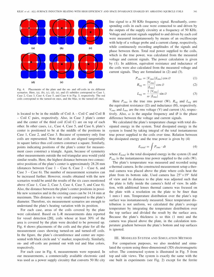
Fig. 2. Schematic of the designed system from side view together withgeometrical parameters. To reflect ratio between the coils’ and the plate’ssizes more clearly, here plate is located to cover two coil units completely.
Fig. 3. Plate’s center positions with respect to coils for six differentmeasurement scenarios.
mica layer can be seen in the inset (Fig. 1(a)). In our proto-type, the mica layer has a thickness of 0.40 mm. Also, there areferrite sticks placed symmetrically around the coil center with45◦ angular intervals between two consecutive sticks below thebottom mica layer, which are used for efficiency enhancement.Ferrites speed up the vessel heating by reversing the magneticflux produced by the coils in lower half space [18], [19].
In our system the coils are placed as close as possible with5 mm distances between them. The distance between the coilsarises because of the constant side lengths of the hob surface.Heating surface is desired to be uniformly occupied by the coilsbut number of the coils is limited by the power circuitry. A steelplate (AISI 430) is placed above the coils. It has a cylindricalshape with 180 mm diameter and 1 mm thickness. It is importantto set the plate’s diameter to be equal to or larger than the sidelength of the repeating unit in the coil array, which is 80 mm(75 mm + 5 mm) here, for catching hot and cold spots thatoccur as a result of constructive and destructive coupling ofthe coils, respectively. Also, the distance between the plate’sbottom surface and the coil units is set to 8 mm to model thethermal isolation material (such as Silargan glass) on the hobsurface. A schematic of the designed system from side viewtogether with geometrical parameters is illustrated in Fig. 2.
Projection coverage of the coils by steel plate depends onthe plate position. Therefore, different coils might be poweredup and heating of the plate may differ depending on its locationon the hob surface. To observe these variations, measure-ments were conducted for the plate’s six different placements.Positions of the plate’s center with respect to coils for thesesix scenarios are shown in Fig. 3.
In the figure, positions of the plate’s center for six differentcases are marked with red dots. In Case 1 and Case 2 plate
KILIC et al.: ALL-SURFACE INDUCTION HEATING WITH HIGH EFFICIENCY AND SPACE INVARIANCE ENABLED BY ARRAYING SQUIRCLE COILS 341
Fig. 4. Placements of the plate and the on- and off-coils in six differentscenarios. Here, (a), (b), (c), (d), (e), and (f) subtitles correspond to Case 1,Case 2, Case 3, Case 4, Case 5, and Case 6 in Fig. 3, respectively. The redcoils correspond to the turned-on ones, and the blue, to the turned-off ones.
is located to be in the middle of Coil A – Coil C and Coil B– Coil C pairs, respectively. Also, in Case 3 plate’s centerand the center of the third coil (Coil C) are on top of eachother. In other cases, i.e., Case 4, Case 5, and Case 6, plate’scenter is positioned to be at the middle of the positions inCase 1, Case 2, and Case 3. Because of symmetry only fourcoils are represented. Note that coils are aligned tangentiallyin square lattice thus coil centers construct a square. Similarly,points indicating positions of the plate’s center for measure-ment cases construct a triangle. Again, because of symmetryother measurements outside the red triangular area would yieldsimilar results. Here, the highest distance between two consec-utive positions of the plate’s center is approximately 28.28 mm(distances between Case 1 – Case 6, Case 2 – Case 6, andCase 3 – Case 6). The number of measurement scenarios canbe increased further. However, results obtained with the newscenarios would be amid the results of the six cases mentionedabove (Case 1, Case 2, Case 3, Case 4, Case 5, and Case 6).Also, the distance between the plate’s center positions in possi-ble new scenarios and in the existing cases can be 14.14 mm atmaximum. This distance is very small compared to the plate’sdiameter. Therefore, six measurement scenarios are enough tounderstand the plate’s heating variation with its position.
For each case, areas of the coils covered by the platewere calculated. Based on L-R measurements data reportedfor vessel detection [20], coils whose at least 30% of thearea is covered by the plate were decided to be powered up.Fig. 4 shows placements of the coils and the plate for all themeasurement cases showing turned-on and turned-off coils.In the figure, the plate’s circumference and center are repre-sented with black circle and ‘x’ marker, respectively. Similarly,on- and off-coils are pointed out with red and blue colors,respectively.
For each case in Fig. 4, measurements were repeated. Inour measurements, a commercially available electronic cardwas used as a power supply circuitry that converts 50 Hz city
line signal to a 50 KHz frequency signal. Resultantly, corre-sponding coils in each case were connected to and driven bythe outputs of the supply circuitry at a frequency of 50 KHz.Voltage and current signals supplied to and driven by each coilwere measured instantaneously by means of an oscilloscopewith help of a voltage probe and a current clamp, respectively,while continuously recording amplitudes of the signals andphase between them. Total real power supplied to the coils,which is the true power, was calculated from the measuredvoltage and current signals. The power calculation is givenby (1). In addition, equivalent resistance and inductance ofthe coils were also calculated from the measured voltage andcurrent signals. They are formulated in (2) and (3).
Prms = |Vrms||Irms| cos∅ (1)
Req = |Vrms||Irms| cos∅ (2)
Leq = 1
ω
|Vrms||Irms| sin∅ (3)
Here Prms is the true rms power (W). Req and Leq arethe equivalent resistance (�) and inductance (H), respectively.Vrms and Irms are the rms voltage (V) and current (A), respec-tively. Also, ω is the angular frequency and Ø is the phasedifference between the voltage and current signals.
We calculated the plate’s temperature change with total dis-sipated energy in the system. Total dissipated energy in thesystem is found by taking integral of the total instantaneoustrue power supplied to the coils over time. Relation betweenthe dissipated energy and the true power is given by (4)
Etotal =∫
Prms · dt (4)
where Etotal is the total dissipated energy in the system (J) andPrms is the instantaneous true power supplied to the coils (W).
The plate’s temperature was measured and recorded usinga thermal camera. In the constructed measurement setup a ther-mal camera was placed above the plate where coils heat theplate from its bottom side. Used camera has 25◦×19◦ fieldof view and its distance to the plate was adjusted such thatthe plate is fully inside the camera’s field of view. In addi-tion, with additional lenses thermal camera was focused onthe plate with a resolution on the plate to be finer than1 mm×1 mm. Temperature distribution over the plate’s topsurface was instantaneously measured. Since temperature dis-tribution is not uniform, we calculated the plate’s averagetemperature by integrating the temperature distribution overthe top surface and divided the result by the surface area.Because the plate’s thickness is so thin (1 mm) and thecamera was placed above the plate, in the calculation tem-perature gradient between the plate’s bottom and top surfacesis ignored.
III. MODELED SYSTEM AND SIMULATION METHOD
For comparison purposes, we also modeled and simu-lated the system using three-dimensional (3D) electromagneticsolver. The constructed system is illustrated in Fig. 5 fromtop and side views. The system is exactly the same with theone built in experiments (see Fig. 2) except for the ferrite

342 IEEE TRANSACTIONS ON CONSUMER ELECTRONICS, VOL. 64, NO. 3, AUGUST 2018
Fig. 5. Schematic of the modeled system from (a) top view and (b) side viewtogether with geometrical parameters. Here, the plate is positioned above thecoils as in Case 1.
layer below the coils. Instead of placing ferrite sticks under-neath each coil, ferrite layer is located under the coils to coverthe whole plane. This makes the modeled system simpler andallows for fast convergence of numerical simulations. In thesystem, ferrite layer has 7 mm thickness and the distancebetween bottom surface of the coils and top surface of theferrite layer is set to 0.40 mm, which is the same with thethickness of the mica layer in our manufactured coil prototypes(see Fig. 1(a)). In the simulations, ferrite layer was modeledto be made of Mn-Zn and mica layers were replaced with freespace. Nine of the outer squircle-inner circular shape coils arestacked in square lattice to construct a 3×3 tangent coil arraystructure. Coils have exactly the same shape with the coilsused in measurements such that they have 30 mm inner diam-eter and 75 mm side lengths. In addition, coils were modeledto be made of perfect electrical conductor (PEC). Since pro-totyped coils are composed of litz strands, in our simulationsby modeling coils with PEC we force currents to flow acrossentire cross section of coil windings. The tangential distancebetween the coils is set to 5 mm to be exactly the same as thecoil distances in the measurement setup. A cylindrical shapesteel plate having 1 mm thickness and 180 mm diameter islocated 8.40 mm above from the coils’ top surface. The dis-tance between the plate and the coils (8.40 mm) includes thedistance between the plate’s bottom surface and the coil units
(8 mm) and the thickness of the mica layer (0.40 mm) in ourmeasurement system (see Fig. 2). Simulations were repeatedvarying the plate’s position in the first three cases, i.e., Case 1,Case 2, and Case 3.
In our simulations, each coil was driven by a separatecurrent source with the specific amplitude determined inmeasurements. In addition, phase difference between currentsignals supplied to consecutive coils was set to 180◦, which isthe same within our measurements. In the simulations, becauseof their complex 3D geometries having rounded edges, coilsand the plate were meshed with tetrahedron shape mesheshaving maximum sizes to be smaller than 2 mm and 5 mm,respectively. In addition, open boundary conditions were setin all directions to model free space and minimize reflectionsfrom the boundaries. The simulations were run at 50 KHzfrequency, which is the same within the measurements. Inthe simulations, we calculated total power transferred to anddissipated on the plate as ohmic loss.
IV. RESULTS AND DISCUSSION
We initially conducted measurements for each case. In allexperiments 180◦ phase difference was applied to consecutivecoils. For instance, in Case 1 (Fig. 4(a)) among four workingcoils two diagonally located coils have currents flowing in one(e.g., in clockwise) direction and the other two cross coils havecurrents flowing in the opposite (e.g., in counter clockwise)direction.
Heating of the plate was observed with help of the thermalcamera. As an exemplary, Fig. 6 shows the temperature distri-butions over the steel plate’s top surface (at 55 s after powerwas turned on) for all the cases.
In the figure, to represent coil locations, boundaries betweenthe coils are marked with dotted lines. As seen, the plate isheated starting from the regions above the adjacent coils’ closesides. This is because of the 180◦ phase difference betweenthe consecutive tangential coil currents. On the other hand,temperature increases are slower in areas above the coils’ cor-ners, where cross coils are being the closest. This is becauseof cross coils’ having currents in the same direction, i.e., 0◦phase difference between. This is one of the reasons why outerrim of the coils were selected to be squircle shape insteadof square. By rounding corners of the square shape, destruc-tive interaction between cross coils is aimed to be decreased.In the figure, temperature distributions obtained in Case 1,Case 2, and Case 3 are almost symmetric with respect tothe plate’s center. This is expected and based on the plate’splacements with respect to the on-coils such that the plate islocated in the middle of the four adjacent tangential on-coilsin Case 1, six neighbor tangential on-coils in Case 2, andfive symmetric and adjacent tangential on-coils in Case 3 (seeFigs. 4(a), (b), and (c)). Small heating variations that violatecomplete symmetry, such as the high temperature area betweenthe two adjacent tangential upper coils in Case 1, are due tomeasurement error of the plate’s not being completely parallelto the coils’ top surfaces. Coupling between a coil and a loadis strongly related with their separation. In the system sincecoils and the plate are close to each other only with 8 mm

KILIC et al.: ALL-SURFACE INDUCTION HEATING WITH HIGH EFFICIENCY AND SPACE INVARIANCE ENABLED BY ARRAYING SQUIRCLE COILS 343
Fig. 6. Temperature distributions over the plate’s top surface at 55 s afterthe power was turned on for all the cases.
distance, small changes in the coil-plate separations violateabsolute symmetry.
Fig. 7 shows changes of average temperature over the platewith time. The nonzero initial times in the figure are becauseof the time required for the thermal camera’s connection andtaking of the image.
In our measurements, the plate was heated up till its averagetemperature passes 100 ◦C. In the figure, at high temperaturesmore time is required to heat up the plate further. In otherwords, temperature increase decelerates as time goes on. Thiscan be explained with high temperature gradient between theplate and the medium, which causes rapid cooling of the plate.
In addition, in Fig. 7 plate’s heating speed is very simi-lar for all the cases. It is important for comparison of thesystem’s heating efficiencies with a plate at different posi-tions. However, heating speed depends on supplied power, too.Therefore, change of the plate’s temperature with total dissi-pated energy in the system was calculated and is presented inFig. 8.
The heating is almost the same for all the cases in the figure.This is expected because real power was supplied to the coilsin a close range in all the measurements. Also, in the figuredecrease in the plate’s heating speed is observed, too. Plate’ssimilar heating for all the cases in Fig. 8 indicates that thesystem’s heating efficiency and speed are independent of theplate position. In other words, the proposed all-surface induc-tion heating system heats a vessel efficiently and quickly allover its surface.
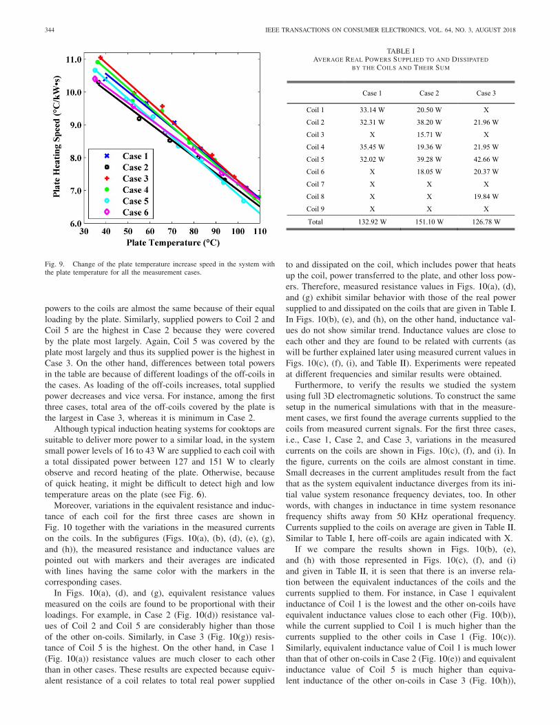
Fig. 9 shows change of the plate’s heating speed with itstemperature for all the measurement cases. Heating speed iscalculated by taking slope of the curves in Fig. 8. Here mark-ers denote the calculated heating speeds and lines are thecorresponding first order fittings. In the figure, decrease inthe plate’s heating speed is clearly seen. For instance, with1 kW·s input energy the plate’s temperature increased morethan 10.0 ◦C if its temperature was around 40 ◦C, but if its
Fig. 7. Average temperature changes over the plate with time for all themeasurement cases.
Fig. 8. Average temperature changes over the plate with total dissipatedenergy in the system for all the measurement cases.
temperature was around 110 ◦C than with 1 kW·s input energythe plate’s temperature increased at most 7.0 ◦C in our system.In addition, in the figure at a constant plate temperature thedifference between temperature increase speeds for the casesis at most 0.9 ◦C/(kW·s). This is expected from Fig. 8 andsupports the result of space-invariant heating of the system.
We further investigated the real powers supplied to eachcoil and their equivalent resistance and inductance values. Theaverage real powers supplied to each coil and their sum over50 seconds are given in Table I for the first three cases. Inthe table off-coils are indicated with X. Also, coils are calledstarting from left top towards the right bottom in ascendingorder. For instance, the left top coil in Fig. 4 is called Coil 1.Similarly, the right top, the left bottom, and the right bottomcoils are called Coil 3, Coil 7, and Coil 9, respectively, inthe table.
As seen, powers supplied to the coils in each case are pro-portional with their loadings. For example, in Case 1 supplied
344 IEEE TRANSACTIONS ON CONSUMER ELECTRONICS, VOL. 64, NO. 3, AUGUST 2018
Fig. 9. Change of the plate temperature increase speed in the system withthe plate temperature for all the measurement cases.
powers to the coils are almost the same because of their equalloading by the plate. Similarly, supplied powers to Coil 2 andCoil 5 are the highest in Case 2 because they were coveredby the plate most largely. Again, Coil 5 was covered by theplate most largely and thus its supplied power is the highest inCase 3. On the other hand, differences between total powersin the table are because of different loadings of the off-coils inthe cases. As loading of the off-coils increases, total suppliedpower decreases and vice versa. For instance, among the firstthree cases, total area of the off-coils covered by the plate isthe largest in Case 3, whereas it is minimum in Case 2.
Although typical induction heating systems for cooktops aresuitable to deliver more power to a similar load, in the systemsmall power levels of 16 to 43 W are supplied to each coil witha total dissipated power between 127 and 151 W to clearlyobserve and record heating of the plate. Otherwise, becauseof quick heating, it might be difficult to detect high and lowtemperature areas on the plate (see Fig. 6).
Moreover, variations in the equivalent resistance and induc-tance of each coil for the first three cases are shown inFig. 10 together with the variations in the measured currentson the coils. In the subfigures (Figs. 10(a), (b), (d), (e), (g),and (h)), the measured resistance and inductance values arepointed out with markers and their averages are indicatedwith lines having the same color with the markers in thecorresponding cases.
In Figs. 10(a), (d), and (g), equivalent resistance valuesmeasured on the coils are found to be proportional with theirloadings. For example, in Case 2 (Fig. 10(d)) resistance val-ues of Coil 2 and Coil 5 are considerably higher than thoseof the other on-coils. Similarly, in Case 3 (Fig. 10(g)) resis-tance of Coil 5 is the highest. On the other hand, in Case 1(Fig. 10(a)) resistance values are much closer to each otherthan in other cases. These results are expected because equiv-alent resistance of a coil relates to total real power supplied
TABLE IAVERAGE REAL POWERS SUPPLIED TO AND DISSIPATED
BY THE COILS AND THEIR SUM
to and dissipated on the coil, which includes power that heatsup the coil, power transferred to the plate, and other loss pow-ers. Therefore, measured resistance values in Figs. 10(a), (d),and (g) exhibit similar behavior with those of the real powersupplied to and dissipated on the coils that are given in Table I.In Figs. 10(b), (e), and (h), on the other hand, inductance val-ues do not show similar trend. Inductance values are close toeach other and they are found to be related with currents (aswill be further explained later using measured current values inFigs. 10(c), (f), (i), and Table II). Experiments were repeatedat different frequencies and similar results were obtained.
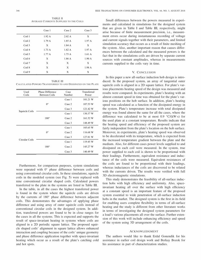
Furthermore, to verify the results we studied the systemusing full 3D electromagnetic solutions. To construct the samesetup in the numerical simulations with that in the measure-ment cases, we first found the average currents supplied to thecoils from measured current signals. For the first three cases,i.e., Case 1, Case 2, and Case 3, variations in the measuredcurrents on the coils are shown in Figs. 10(c), (f), and (i). Inthe figure, currents on the coils are almost constant in time.Small decreases in the current amplitudes result from the factthat as the system equivalent inductance diverges from its ini-tial value system resonance frequency deviates, too. In otherwords, with changes in inductance in time system resonancefrequency shifts away from 50 KHz operational frequency.Currents supplied to the coils on average are given in Table II.Similar to Table I, here off-coils are again indicated with X.
If we compare the results shown in Figs. 10(b), (e),and (h) with those represented in Figs. 10(c), (f), and (i)and given in Table II, it is seen that there is an inverse rela-tion between the equivalent inductances of the coils and thecurrents supplied to them. For instance, in Case 1 equivalentinductance of Coil 1 is the lowest and the other on-coils haveequivalent inductance values close to each other (Fig. 10(b)),while the current supplied to Coil 1 is much higher than thecurrents supplied to the other coils in Case 1 (Fig. 10(c)).Similarly, equivalent inductance value of Coil 1 is much lowerthan that of other on-coils in Case 2 (Fig. 10(e)) and equivalentinductance value of Coil 5 is much higher than equiva-lent inductance of the other on-coils in Case 3 (Fig. 10(h)),

KILIC et al.: ALL-SURFACE INDUCTION HEATING WITH HIGH EFFICIENCY AND SPACE INVARIANCE ENABLED BY ARRAYING SQUIRCLE COILS 345
Fig. 10. Variations in the equivalent resistance ((a), (d), (g)) and equivalent inductance ((b), (e), (h)) of the coils together with the measured currents onthe coils ((c), (f), (i)) over time for three different scenarios: (a)-(c) Case 1, (d)-(f) Case 2, and (g)-(i) Case 3. Here markers denote the measured resistance,inductance, and current values. In addition, lines indicate averages of the measured values in each case in resistance and inductance plots, whereas linesrepresent the corresponding first order fittings of the measured currents in current plots.
whereas current supplied to Coil 1 is the highest in Case 2(Fig. 10(f)) and current supplied to Coil 5 is the lowest inCase 3 (Fig. 10(i)).
In simulations, total power transferred to and dissipated onthe plate was calculated as 130.37 W, 161.52 W, and 148.49 Wfor Case 1, Case 2, and Case 3, respectively. On the otherhand, in Table I, total power supplied to the coils, which isthe total dissipated power in the coils and the plate, was found
as 132.92 W, 151.10 W, and 126.78 W. Since the prototypedcoils in experiments consist of several litz strands, it would bea fair assumption to ignore power dissipated on coils for theirself-heating. In other words, most of the total power suppliedto the coils in Table I is the power transferred to the plate.Therefore, it can be deduced that the calculated powers in thesimulations and the measured powers in the experiments areclose to each other.
346 IEEE TRANSACTIONS ON CONSUMER ELECTRONICS, VOL. 64, NO. 3, AUGUST 2018
TABLE IIAVERAGE CURRENTS SUPPLIED TO THE COILS
TABLE IIICALCULATED POWERS TRANSFERRED TO AND DISSIPATED ON THE PLATE
Furthermore, for comparison purposes, system simulationswere repeated with 0◦ phase difference between coils andusing conventional circular coils. In these simulations, squirclecoils in the modeled system (see Fig. 5) were replaced withnine conventional circular shaped coils. Calculated powerstransferred to the plate in the systems are listed in Table III.
In the table, in all the cases the highest transferred poweris found in the system where the squircle coils are drivenby the currents of 180◦ phase difference between adjacentcoils. This demonstrates the advantages of applying phasedifference and using array of outer squircle coils instead ofconventional circular coils in the designed system. In addi-tion, transferred powers are found to be in close ranges forthe cases in all the systems. This is expected and supports theresult of space-invariant heating in systems where coils arealigned in a 2D periodic square lattice. The proposed squir-cle shaped coils’ alignment in square lattice allows enhancedinteraction and coupling because of the coils’ unique geometryand phase difference application together with space-invariantheating which occur as a result of the plate’s catching coldand hot spots.
Small differences between the powers measured in experi-ments and calculated in simulations for the designed systemthat are given in Table I and Table III, respectively, mightarise because of finite measurement precision, i.e., measure-ment errors occur during instantaneous recording of voltageand current signals together with their parameters, and limitedsimulation accuracy that occurs as a result of finite meshing ofthe system. Also, another important reason that causes differ-ences between the calculated and the measured powers is thefact that in the simulations coils are driven by separate currentsources with constant amplitudes, whereas in measurementscurrents supplied to the coils vary in time.
V. CONCLUSION
In this paper a new all-surface induction hob design is intro-duced. In the proposed system, an array of tangential outersquircle coils is aligned in a 2D square lattice. For plate’s var-ious placements heating speed of the design was measured andresults were compared. In experiments, plate’s heating with analmost constant speed in time was obtained for the plate’s var-ious positions on the hob surface. In addition, plate’s heatingspeed was calculated as a function of the dissipated energy inthe system. Plate’s temperature increase with total dissipatedenergy was found almost the same for all the cases, where thedifference was calculated to be at most 0.9 ◦C/(kW·s) forthe used plate at a constant temperature. Results indicate thatthe heating speed and efficiency of the proposed system arefairly independent from the plate’s location on the hob surface.Moreover, in experiments, plate’s heating speed was observedto be decelerated with its temperature, which is expected fromthe increased temperature gradient between the plate and themedium. Also, for different cases power levels supplied to anddissipated on each coil were measured. In the system, truepower supplied to each coil is shown to be proportional withtheir loadings. Furthermore, equivalent resistance and induc-tance of the coils were measured. Equivalent resistances ofthe coils are found to be proportional with their loadings,whereas inductances of the coils are discovered to be relatedwith the currents driven. The results were verified with full3D electromagnetic simulations.
This study demonstrates the feasibility of all-surface induc-tion hobs with high efficiency and uniformity. Also, space-invariant heating all over the surface with high efficiencyat a constant speed is an important feature of the proposedsystem essential to wide penetration of all-surface inductionhobs in the market. The designed system is the first in its fieldfor enabling users complete flexibility in terms of all-surfaceheating and the study is different from other literature worksin terms of investigating the designed system parameters fora load’s various placements all over the surface. Further exten-sion of this work will include enhancing efficiency and speedof the system using 3D arrangement of the coils.
ACKNOWLEDGMENT
The authors would like to thank Erdal Gonendik for hisassistance in earlier coil design work and Berkay Bozok forhis assistance in part of characterization studies.

KILIC et al.: ALL-SURFACE INDUCTION HEATING WITH HIGH EFFICIENCY AND SPACE INVARIANCE ENABLED BY ARRAYING SQUIRCLE COILS 347
REFERENCES
[1] A. Mühlbauer, History of Induction Heating and Melting. Essen,Germany: Vulkan-Verlag, 2008.
[2] T. Tanaka, “A new induction cooking range for heating any kind of metalvessels,” IEEE Trans. Consum. Electron., vol. 35, no. 3, pp. 635–641,Aug. 1989, doi: 10.1109/30.44329.
[3] J. Moon, H. Hwang, B. Jo, H.-A. Shin, and S.-W. Kim, “Designof a 5-W power receiver for 6.78 MHz resonant wireless powertransfer system with power supply switching circuit,” IEEE Trans.Consum. Electron., vol. 62, no. 4, pp. 349–354, Nov. 2016,doi: 10.1109/TCE.2016.7838086.
[4] V. T. Nguyen, S. H. Kang, J. H. Choi, and C. W. Jung,“Magnetic resonance wireless power transfer using three-coil systemwith single planar receiver for laptop applications,” IEEE Trans.Consum. Electron., vol. 61, no. 2, pp. 160–166, May 2015,doi: 10.1109/TCE.2015.7150569.
[5] D. Dai and J. Liu, “Design of a practical human-powered contactlesscharger for cellphone,” IEEE Trans. Consum. Electron., vol. 59, no. 3,pp. 476–482, Aug. 2013, doi: 10.1109/TCE.2013.6626227.
[6] H. Hoang, S. Lee, Y. Kim, Y. Choi, and F. Bien, “An adaptive tech-nique to improve wireless power transfer for consumer electronics,”IEEE Trans. Consum. Electron., vol. 58, no. 2, pp. 327–332, May 2012,doi: 10.1109/TCE.2012.6227430.
[7] O. Lucia, J. Acero, C. Carretero, and J. M. Burdio, “Inductionheating appliances: Toward more flexible cooking surfaces,”IEEE Ind. Electron. Mag., vol. 7, no. 3, pp. 35–47, Sep. 2013,doi: 10.1109/MIE.2013.2247795.
[8] J. Acero et al., “The domestic induction heating appliance: An overviewof recent research,” in Proc. IEEE Appl. Power Electron. Conf. Expo.(APEC), Austin, TX, USA, 2008, pp. 651–657.
[9] Ó. Lucia, J. M. Burdio, L. A. Barragan, C. Carretero, and J. Acero,“Series resonant multiinverter with discontinuous-mode control forimproved light-load operation,” IEEE Trans. Ind. Electron., vol. 58,no. 11, pp. 5163–5171, Nov. 2011, doi: 10.1109/TIE.2011.2126541.
[10] Ó. Lucia, C. Carretero, J. M. Burdio, J. Acero, and F. Almazan,“Multiple-output resonant matrix converter for multiple inductionheaters,” IEEE Trans. Ind. Appl., vol. 48, no. 4, pp. 1387–1396,Jul./Aug. 2012, doi: 10.1109/TIA.2012.2199456.
[11] Ó. Lucia, H. Sarnago, and J. M. Burdio, “Soft-stop optimal tra-jectory control for improved performance of the series-resonantmultiinverter for domestic induction heating applications,” IEEETrans. Ind. Electron., vol. 62, no. 10, pp. 6251–6259, Oct. 2015,doi: 10.1109/TIE.2015.2417132.
[12] K. Leidig and M. Herzog, “Induction cooking hob,” EuropeanPatent EP 2 265 088 B1, Jun. 27, 2012.
[13] J. Acero, C. Carretero, Ó. Lucia, R. Alonso, and J. M. Burdio, “Mutualimpedance of small ring-type coils for multiwinding induction heatingappliances,” IEEE Trans. Power Electron., vol. 28, no. 2, pp. 1025–1035,Feb. 2013, doi: 10.1109/TPEL.2012.2205270.
[14] F. Forest et al., “Frequency-synchronized resonant converters forthe supply of multiwinding coils in induction cooking appliances,”IEEE Trans. Ind. Electron., vol. 54, no. 1, pp. 441–452, Feb. 2007,doi: 10.1109/TIE.2006.888797.
[15] V. T. Kilic, E. Unal, E. Gonendik, N. Yilmaz, and H. V. Demir, “Stronglycoupled outer squircle–inner circular coil architecture for enhancedinduction over large areas,” IEEE Trans. Ind. Electron., vol. 63, no. 12,pp. 7478–7487, Dec. 2016, doi: 10.1109/TIE.2016.2594228.
[16] F. Sanz, C. Franco, C. Sagues, D. Paesa, and S. Llorente, “Flexiblecooking zone with 2D mobile inductors in induction hobs,” in Proc.IEEE Ind. Electron. Soc. Conf. (IECON), Montreal, QC, Canada, 2012,pp. 3262–3267.
[17] H. N. Pham, H. Fujita, K. Ozaki, and N. Uchida, “Estimating methodof heat distribution using 3-D resistance matrix for zone-control induc-tion heating systems,” IEEE Trans. Power Electron., vol. 27, no. 7,pp. 3374–3382, Jul. 2012, doi: 10.1109/TPEL.2011.2179984.
[18] W. A. Roshen and D. E. Turcotte, “Planar inductors on magnetic sub-strates,” IEEE Trans. Magn., vol. 24, no. 6, pp. 3213–3216, Nov. 1988,doi: 10.1109/20.92379.
[19] W. A. Roshen, “Effect of finite thickness of magnetic substrate on planarinductors,” IEEE Trans. Magn., vol. 26, no. 1, pp. 270–275, Jan. 1990,doi: 10.1109/20.50553.
[20] V. T. Kilic, E. Unal, and H. V. Demir, “Wireless metal detection and sur-face coverage sensing for all-surface induction heating,” Sensors, vol. 16,no. 3, p. 363, Mar. 2016, doi: 10.3390/s16030363.
Veli Tayfun Kilic (S’14–M’17) was born in Adana,Turkey, in 1987. He graduated from Adana ScienceHigh School, Adana, and received the B.S., M.S.,and Ph.D. degrees from Bilkent University, Ankara,Turkey, in 2009, 2011, and 2017, respectively, all inelectrical and electronics engineering. His researchfocus is high-efficiency inductive energy transfer andapplications.
From 2009 to 2017, he was a Research Assistantwith the Electrical and Electronics EngineeringDepartment, Bilkent University. From 2012 to 2013,
he was a Design Engineer with Mikes Company. From 2014 to 2018, hewas a Researcher with TUBITAK, the Scientific and Technological ResearchCouncil of Turkey. In 2018, he joined Abdullah Gul University, Kayseri,Turkey, where he is currently an Assistant Professor with the Departmentof Electrical and Electronics Engineering. His research interests include radiofrequency systems, near-field and far-field electromagnetic coupling, radiofrequency antennas, plasmonic antennas, and radio frequency circuits.
Emre Unal received the B.S. degree in electrical andelectronics engineering from Hacettepe University,Ankara, Turkey, in 2005. He is a full-time ResearchEngineer with the Institute of Materials Science andNanotechnology, Bilkent University, Ankara, underthe supervision of Prof. H. V. Demir, where he isresearching on the development of microwave andoptoelectronic devices.
Namik Yilmaz received the B.S. and M.S. degreesin electrical engineering from Istanbul TechnicalUniversity, Istanbul, Turkey, in 1997 and 2000,respectively, where he is currently pursuing thePh.D. degree in electrical engineering. He has beenwith the Power Electronics Group, Arcelik A.S.,since 2000. His main interests include design ofmotor control hardware and algorithms, designof resonant inverter topologies, and coils andalgorithms for domestic induction cooking andmicrowave heating.
Hilmi Volkan Demir (M’04–SM’11) received theB.S. degree in electrical and electronics engineer-ing from Bilkent University, Ankara, Turkey, in1998 and the M.S. and Ph.D. degrees in electri-cal engineering from Stanford University, Stanford,CA, USA, in 2000 and 2004, respectively. In2004, he joined Bilkent University, where heis currently a Professor with joint appointmentswith the Department of Electrical and ElectronicsEngineering and the Department of Physics and isalso with the Institute of Materials Science and
Nanotechnology. He is also a fellow of National Research Foundation inSingapore and a Professor with Nanyang Technological University. Hisresearch interests include the development of innovative optoelectronic andRF devices.
He was a recipient of the European Union Marie Curie Fellowship, theTurkish National Academy of Sciences Distinguished Young Scientist Award,the European Science Foundation-European Young Investigator Award, andthe Nanyang Award for Research Excellence.