all about the railway engine
DESCRIPTION
RAILWAY ENGINETRANSCRIPT

2.1 TWO STROKE ENGINE
The injection of fuel into the cylinder of the two stroke engine is handled in the same
manner as the four stroke engine. As the piston nears Top Dead Center (TDC) the fuel
injector delivers an atomized spray of fuel into the cylinder. The fuel combines with the
air and is ignited by the high temperature. Rotation of the crankshaft carries the piston
past TDC as the fuel begins to combust with the air. Combustion of the fuel and air
causes the pressure in the cylinder to rise rapidly. This pressure expands in all directions,
pushing the piston downwards with a greater force than it took to initially compress the
air. As in the four stroke engine, this force on the piston is converted into a rotary motion
on the crankshaft, providing a useable mechanical force.
OPERATION
Assuming that the piston is at the bottom of its stroke and just starting up, the air
intake ports and the exhaust valves will be open. Air under pressure enters the cylinder
through the liner ports, pushes the exhaust gases, remaining from the previous power
stroke, out through the exhaust valves and fills the cylinder with a fresh supply of air.
When the piston is 45° after bottom dead center, the air intake ports will be closed by the
piston. Shortly after the air intake ports are closed, the exhaust valves will also be closed,
and the fresh air will be trapped in the cylinder. Closing the exhaust valves after the
intake air ports provides for the greatest efficiency in cylinder scavenging of combustion
gases.
As the piston continues upward, it compresses the trapped air into a very small volume.
Just before the piston reaches top dead center, the fuel injector sprays fuel into the
cylinder. Ignition of the fuel is practically instantaneous, due to the temperature of the
compressed air trapped in the top of the cylinder. The fuel burns rapidly as the piston is
forced down on the power stroke of the piston. As shown in the timing diagram, the
piston continues downward in the power stroke until the exhaust valves open. The
exhaust valves are opened ahead of the air intake ports to permit most of the combustion

gases to escape and reduce the pressure in the cylinder. When the air intake ports are
uncovered by the piston at 45° B.B.D.C. as it continues downward, air from the air box
under pressure can immediately enter the cylinder, scavenging the remaining combustion
gases from the cylinder and providing fresh air for combustion. The piston is again at the
original starting point and the cycle of events is repeated.
OPERATION OF ENGINE
V-ENGINE ARRANGEMENT The two stroke Electro-Motives diesel engine is a " Narrow V" type design
consisting of two rows of engine cylinders arranged with an angle of 45º between them.
Opposing cylinders share a common crankshaft eccentric. The rear of the engine is
usually called the flywheel end since this is where the main generator is driven from. The
camshaft gear train and auxiliary generator drive are located on the rear of the engine.
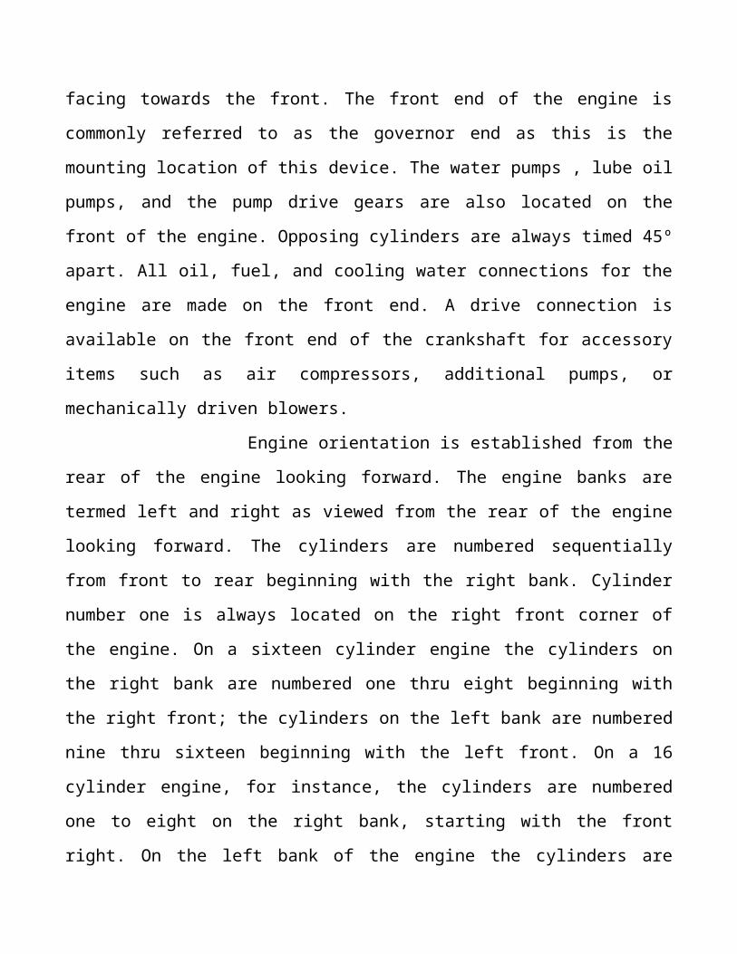
Engine rotation is left hand, or anti-clockwise as viewed from the rear facing towards the
front. The front end of the engine is commonly referred to as the governor end as this is
the mounting location of this device. The water pumps , lube oil pumps, and the pump

drive gears are also located on the front of the engine. Opposing cylinders are always
timed 45º apart. All oil, fuel, and cooling water connections for the engine are made on
the front end. A drive connection is available on the front end of the crankshaft for
accessory items such as air compressors, additional pumps, or mechanically driven
blowers.
Engine orientation is established from the rear of the engine looking forward.
The engine banks are termed left and right as viewed from the rear of the engine looking
forward. The cylinders are numbered sequentially from front to rear beginning with the
right bank. Cylinder number one is always located on the right front corner of the engine.
On a sixteen cylinder engine the cylinders on the right bank are numbered one thru eight
beginning with the right front; the cylinders on the left bank are numbered nine thru
sixteen beginning with the left front. On a 16 cylinder engine, for instance, the cylinders
are numbered one to eight on the right bank, starting with the front right. On the left bank
of the engine the cylinders are numbered nine to sixteen, starting with the front left. This
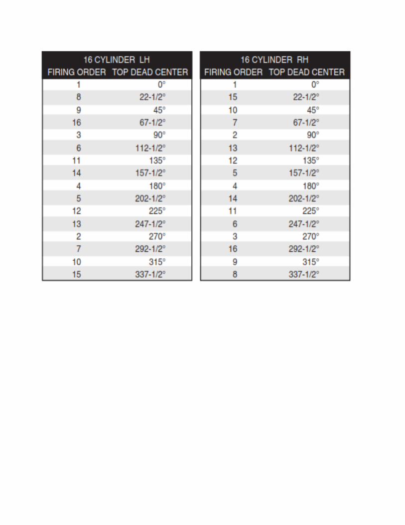
gives us pairs of cylinders such as 1 and 9, 8 and 16. Opposing cylinders fire 45 degrees
of crankshaft rotation apart due to the 45 degree "V" layout of the engine. A 16 cylinder
engine has one cylinder firing every 22 -1/2 degrees of crankshaft rotation (360/16).
Since the timing between each power pulse is equal (22 1/2 degrees), the 16 cylinder
engine has a balanced firing order. The firing order for a 16 cylinder example engine is 1,
8, 9, 16, 3, 6, 11, 14, 4, 5,12, 13, 2, 7, 10, 15. The exhaust system is located on the top of
the engine between the cylinder banks. For engines equipped with mechanical blowers,
the exhaust is collected in the manifold and allowed to vent to atmosphere.

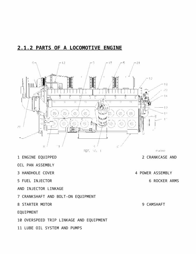
2.1.2 PARTS OF A LOCOMOTIVE ENGINE
1 ENGINE EQUIPPED 2 CRANKCASE AND OIL PAN ASSEMBLY
3 HANDHOLE COVER 4 POWER ASSEMBLY
5 FUEL INJECTOR 6 ROCKER ARMS AND INJECTOR LINKAGE
7 CRANKSHAFT AND BOLT-ON EQUIPMENT
8 STARTER MOTOR 9 CAMSHAFT EQUIPMENT
10 OVERSPEED TRIP LINKAGE AND EQUIPMENT
11 LUBE OIL SYSTEM AND PUMPS
12 COOLING SYSTEM AND PUMPS
13 FUEL PIPING AND FILTER
14 GOVERNOR BOOSTER PUMP ASSEMBLY
15 CYLINDER HEAD COVERS AND SUPPORT FRAMES
16 ACCESSORY DRIVE HOUSING
17 PRESSURE DETECTOR APPLICATION
18 AUXILIARY GENERATOR DRIVE
19 GOVERNOR
20 GOVERNOR DRIVE EQUIPMENT
21 EXHAUST CHAMBER AND HEAT SHIELD
22 TURBOCHARGER
2.1.3 VARIOUS COMPONENTS OF V-ENGINE
POWER ASSEMBLY
FUEL OIL SYSTEM
COOLING WATER SYSTEM
LUBE OIL SYSTEM
AIR INTAKE SYSTEM
COMPRESSED AIR SYSTEM
2.2.1 POWER ASSEMBLY
Each cylinder of the diesel engine consists of a power pack or power assembly which is
made up of the following parts:
• cylinder liner
• cylinder head
• piston and rings
• piston carrier assembly
• connecting rod assembly
CYLINDER LINER
The cylinder liner is a cast iron assembly with brazed on outer sleeves. The unit
comprises the cylinder itself, cylinder water jacket, and intake ports. The intake ports are
arranged in a row around the circumference of the liner. This arrangement ensures
complete cylinder scavenging. Coolant enters the liner from a water manifold in the air
box, through a water jumper, into a flanged connection on the front lower side of the
liner. Inside the water inlet is a deflector that prevents erosion and cold spots on the liner.
CYLINDER HEAD
The cylinder head is a cast iron component, with passages for coolant and exhaust gases.
Four exhaust valves control the flow of gases from the cylinder, through the passages,
into the exhaust runner in the crankcase. These valves are run in replaceable nitride valve

guides, and held in place by valve springs and keepers. The bottom of the head forms the
top of the cylinder and the mating surface with the top of the liner. Twelve passages
around the outer diameter allow coolant to flow from the liner to the cylinder head. The
coolant flows over the inside of the cylinder head around the valve guide bores and
injector well, and exits the head by a discharge elbow into the engine block. From there
the coolant is collected from all cylinders and flows to the radiators.
PISTON AND PISTON RINGS
The pistons in EMD engines are a cast iron alloy. The undercrown of the piston is cooled
by lubricating oil supplied by the piston cooling section of the main lube oil pump to the
piston cooling pipes. This oil circulates from the piston cooling pipes through the piston
carrier to the fins in the undercrown area to remove combustion heat from the piston
crown area. The piston has four compression rings on the upper portion to seal the
cylinder from the crankcase. These rings are either ductile steel for use with chrome
plated liners, or chrome plated for use with cast iron finished liners. Two oil control rings
are positioned on the lower portion of the piston skirt to control liner lubrication and
prevent excess oil consumption.
PISTON CARRIER
The piston rides on a "trunnion" type carrier assembly. The carrier is fitted inside the
piston, and a thrust washer on top of the carrier allows the piston to rotate freely in the
cylinder. The piston is retained by a large snap ring fitting into a groove in the lower
inside piston skirt. The snap ring is not loaded during normal operation as the piston is
driven downward with each power stroke. If an injector is cut out or a cylinder is not
firing, the snap ring is loaded as it must pull the piston down.

CONNECTING ROD
The piston is retained by a large snap ring fitting into a groove in the lower inside piston
skirt. The snap ring is not loaded during normal operation as the piston is driven
downward with each power stroke. If an injector is cut out or a cylinder is not firing, the
snap ring is loaded as it must pull the piston down. The connecting rods consist of fork
rods, blade rods, basket halves, and a set of connecting rod lower bearings with the piston
pins bolted directly to the connecting rods.
CYLINDER HEAD
The cylinder head is a cast iron component, with passages for coolant and exhaust gases.
Four exhaust valves control the flow of gases from the cylinder, through the passages,
into the exhaust runner in the crankcase. These valves are run in replaceable nitrided
valve guides, and held in place by valve springs and keepers. The bottom of the head, or
fireface, forms the top of the cylinder and the mating surface with the top of the liner.
Twelve passages around the outer diameter of the fireface allow coolant to flow from the
liner to the cylinder head. The coolant flows over the inside of the fireface, around the
valve guide bores and injector well, and exits the head by a discharge elbow into the
engine block. From there the coolant is collected from all cylinders and flows to the
radiators. The top of the head is machined for mounting of the injector, rocker arm

assembly, and power assembly hold down crabs. The fuel injector is held in the injector
well by a hold down crab, and is clamped against a copper seal in the bottom of the well
to prevent combustion/compression leakage from the cylinder.
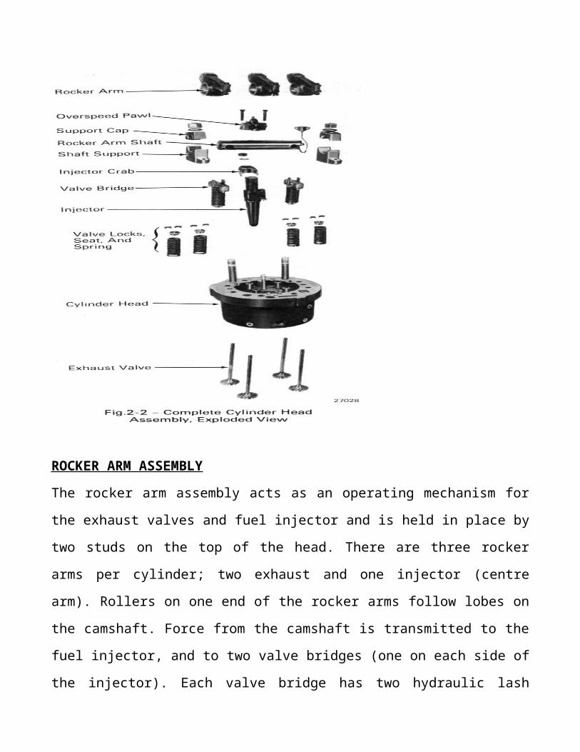
ROCKER ARM ASSEMBLY
The rocker arm assembly acts as an operating mechanism for the exhaust valves and fuel
injector and is held in place by two studs on the top of the head. There are three rocker
arms per cylinder; two exhaust and one injector (centre arm). Rollers on one end of the
rocker arms follow lobes on the camshaft. Force from the camshaft is transmitted to the
fuel injector, and to two valve bridges (one on each side of the injector). Each valve
bridge has two hydraulic lash adjusters that open the exhaust valves and maintain proper
valve adjustment.

REAR GEAR TRAIN
The rear gear train provides power to drive the camshafts and, depending on engine
model, the
blowers/or turbocharger. The gear train is located on the rear, or flywheel end of the
engine
and consists of:
• crankshaft gear
• #1 (or lower) idler gear
• #2 (or upper) idler gear
• left and right camshaft gears
• turbo drive gear or;
• blower drive gears

The camshafts are driven at a 1:1 ratio, they make one revolution every revolution of the
crankshaft.
The camshafts are driven off the #2 idler gear. The left bank camshaft gear meshes with
the #2 idler and then drives the right bank camshaft. The camshafts therefore rotate in
opposite directions inboard towards each other. The #2 idler has an extra row of teeth that
are used to drive the turbocharger. The idler stub shaft bracket provides a mounting
fixture for the idler gears and is bolted to the rear of the engine block. This bracket also
contains oil passages to direct lubricating oil from the oil gallery in the engine block to
the rear gear train, camshafts and turbo if equipped.
CLUTCH/SPRING DRIVE GEAR
On turbocharged engines there are two types of number 2 idler gear / turbo drive gear
assemblies, the spring drive gear, and the clutch drive gear. On turbocharged engines
there are two types of number 2 idler gear / turbo drive gear assemblies, the spring drive
gear, and the clutch drive gear. The clutch drive gear, introduced on the 710 engine is

similar to design and function to the internal turbo clutch, but is larger and much
stronger. Another advantage to this design is that this clutch can be removed and
inspected or rebuilt without disassembling the turbocharger. The spring drive gear is used
on engines with internal clutch turbochargers to absorb torsional vibration and cushion
the gear train from the shock loads of the turbo clutch engaging and disengaging. On
right hand rotation applications, the #2 idler gear drives the right bank camshaft gear,
which keeps the camshaft gear rotation inboard towards each other. Right
hand rotation engine turbochargers have an extra idler gear added so the turbo rotates the
same direction as a left hand rotation engine turbocharger.
ACCESSORY DRIVE
The accessory drive gear train is located at the front, or governor end of the engine and is
used to power the oil pumps, water pumps, and governor.
The components are:
• accessory drive gear
• scavenging oil pump gear
• main lube and piston cooling pump gear
• governor drive gear
• water pump gears

The accessory drive gear is a coil spring dampened gear assembly that provides a smooth
flow of power from the crankshaft to the accessory gears. The scavenging pump drive
gear is powered directly off this gear, as is the main lube and piston cooling pump drive
gear. The governor drive gear is mounted on a stub shaft assembly above the main lube
drive gear. As the main lube pump drive gear is rotated by the accessory drive gear, the
governor drive gear turns, powering the governor and the left and right water pump drive
gears. The governor angle drive is splined onto the center of the governor drive gear. The
gear train is enclosed by the accessory drive housing which provides mounting fixtures
for the pumps and governor.