algorex - cs1140 operators manual (ep5)
DESCRIPTION
CS1140TRANSCRIPT

Cerberus® CS1140Fire detection system control unit withcontrol console
Operating instructions
Fire & Security ProductsSiemens Building Technologies Group
Related to software ”Standard international” (EP5)

Data and design subject to change
without notice. / Supply subject to
availability.
� Copyright by
Siemens Building Technologies AG
Wir behalten uns alle Rechte an
diesem Dokument und an dem in ihm
dargestellten Gegenstand vor. Der
Empfänger anerkennt diese Rechte
und wird dieses Dokument nicht ohne
unsere vorgängige schriftliche
Ermächtigung ganz oder teilweise
Dritten zugänglich machen oder
ausserhalb des Zweckes verwenden,
zu dem es ihm übergeben worden ist.
We reserve all rights in this document
and in the subject thereof. By
acceptance of the document the
recipient acknowledges these rights
and undertakes not to publish the
document nor the subject thereof in
full or in part, nor to make them
available to any third party without our
prior express written authorization,
nor to use it for any purpose other
than for which it was delivered to him.
Nous nous réservons tous les droits
sur ce document, ainsi que sur l’objet
y figurant. La partie recevant ce
document reconnaît ces droits et elle
s’engage à ne pas le rendre
accessible à des tiers, même
partiellement, sans notre autorisation
écrite préalable et à ne pas
l’employer à des fins autres que
celles pour lesquelles il lui a été
remis.
Ci riserviamo ogni diritto relativo al
presente documento e sull’oggetto
illustrato in esso. La parte che riceve
il documento si impegna a non
renderlo accessibile a terzi, né per
intero né in parte, senza la nostra
previa autorizzazione scritta ed a non
usarlo per altri scopi di quello per il
quale è stato rilasciato.

10.1999
I
Fire & Security Products
Siemens Building Technologies Group
Content
Quick reference instructions 1. . . . . . . . . . . . . . . . . . . . . . . . . . . . . . . . . . . . . . . . . . . . . . . . .
Introduction 3. . . . . . . . . . . . . . . . . . . . . . . . . . . . . . . . . . . . . . . . . . . . . . . . . . . . . . . . . . . . . . . .
Control console layout 4. . . . . . . . . . . . . . . . . . . . . . . . . . . . . . . . . . . . . . . . . . . . . . . . . . . . . .
Operating access 6. . . . . . . . . . . . . . . . . . . . . . . . . . . . . . . . . . . . . . . . . . . . . . . . . . . . . . . . . . .
Message categories 7. . . . . . . . . . . . . . . . . . . . . . . . . . . . . . . . . . . . . . . . . . . . . . . . . . . . . . . .
Terminology ’Area’, ’Section’and ’Zone’ 8. . . . . . . . . . . . . . . . . . . . . . . . . . . . . . . . . . . . . . . . . . . . . . . . . . . . . . . . . . . . . . . . .
Normal operation 9. . . . . . . . . . . . . . . . . . . . . . . . . . . . . . . . . . . . . . . . . . . . . . . . . . . . . . . . . . .
Operating states ’Present’ and ’Absent’ 10. . . . . . . . . . . . . . . . . . . . . . . . . . . . . . . . . . . . . . . . . . . . . . . . . . . . . .
Alarm 11. . . . . . . . . . . . . . . . . . . . . . . . . . . . . . . . . . . . . . . . . . . . . . . . . . . . . . . . . . . . . . . . . . . .
Detector zone, temporary isolation 14. . . . . . . . . . . . . . . . . . . . . . . . . . . . . . . . . . . . . . . . . . . . . . . . . . . . . . . .
Isolation of detectors 16. . . . . . . . . . . . . . . . . . . . . . . . . . . . . . . . . . . . . . . . . . . . . . . . . . . . . . .
Fault 17. . . . . . . . . . . . . . . . . . . . . . . . . . . . . . . . . . . . . . . . . . . . . . . . . . . . . . . . . . . . . . . . . . . . .
’Detector test’ mode 18. . . . . . . . . . . . . . . . . . . . . . . . . . . . . . . . . . . . . . . . . . . . . . . . . . . . . . .
’Installation test’ mode 22. . . . . . . . . . . . . . . . . . . . . . . . . . . . . . . . . . . . . . . . . . . . . . . . . . . . .
’Renovation’ mode 23. . . . . . . . . . . . . . . . . . . . . . . . . . . . . . . . . . . . . . . . . . . . . . . . . . . . . . . . .
Remote transmission OFF/ON 24. . . . . . . . . . . . . . . . . . . . . . . . . . . . . . . . . . . . . . . . . . . . . .
Alarm devices OFF/ON 25. . . . . . . . . . . . . . . . . . . . . . . . . . . . . . . . . . . . . . . . . . . . . . . . . . . . .
Printer OFF/ON 26. . . . . . . . . . . . . . . . . . . . . . . . . . . . . . . . . . . . . . . . . . . . . . . . . . . . . . . . . . .
Printer: Paper replenishing 27. . . . . . . . . . . . . . . . . . . . . . . . . . . . . . . . . . . . . . . . . . . . . . . . . .
Lamp test 28. . . . . . . . . . . . . . . . . . . . . . . . . . . . . . . . . . . . . . . . . . . . . . . . . . . . . . . . . . . . . . . .
Alarm counter 29. . . . . . . . . . . . . . . . . . . . . . . . . . . . . . . . . . . . . . . . . . . . . . . . . . . . . . . . . . . . .
Event memory 30. . . . . . . . . . . . . . . . . . . . . . . . . . . . . . . . . . . . . . . . . . . . . . . . . . . . . . . . . . . .
Set clock and date 31. . . . . . . . . . . . . . . . . . . . . . . . . . . . . . . . . . . . . . . . . . . . . . . . . . . . . . . . .
Overview operating menus 32. . . . . . . . . . . . . . . . . . . . . . . . . . . . . . . . . . . . . . . . . . . . . . . . .

10.1999
II
Fire & Security Products
Siemens Building Technologies Group

e1033e10.1999
1
Fire & Security Products
Siemens Building Technologies Group
Quick reference instructions
Alarm, what to do ?
1 2 3
4 5 6
7 8 9
ok
F2
F1
0 C
Acknowledge
Reset
Alarms FaultsIsolationInformation
Alarm device Alarm deviceAlarm devicePremisesactive faultoffmanned
Remote alarm Remote transmissionRemote alarmAlarm delayactive faultoffoff
System SystemControl functionDetectoron faultofftest mode
This display can show 2 messages spontaneously.
=> Upper section shows 1st message
=> Lower section shows 2nd message
If more than 2 messages have been reported,scrolling becomes necessary in order to show allreported messages in the ’upper section’ (one afterthe other).
=> Scrolling is done by pressing key ’scroll’ or with the arrow keys
1st message+ «scroll box»
last message
FIRE BRIGADE REQUESTED Total: 201 AUTOM.FIRE ALARM
Main building / 1st floorroom 104
02 AUTOM.FIRE ALARMMain building / 1st floorroom 104
select MESSAGE CATEGORY F1:function
uppersection
lowersection
C A
B
C
ALARM
select MESSAGE CATEGORY F1:function
FIRE BRIGADE REQUESTED Total: 1
Main building / 1st floor01 AUTOM.FIRE ALARM
1. Press the ’acknowledge’ key
2. Read top line of display
FIRE BRIGADE in 2:35 Total: 1
01 AUTOM.FIRE ALARMMain building / 1st floorroom 104
select MESSAGE CATEGORY F1:function
CALL fire brigade: TEL.118 Total: 101 AUTOM.FIRE ALARM
Main building / 1st floorroom 104
select MESSAGE CATEGORY F1:function
=> 3 different messages possible
⇒ Alarm message to fire brigade already transmitted
⇒ Alarm message to fire brigade will be sent in ..min ..sec
– remaining time shown as ’countdown’
No transmission to fire brigade⇒ call fire brigade by telephone
either; if– remote transmission isolated– remote transmission device blocked or defective– not connected to fire brigade
3. Read fire location on the display
4. Go to indicated fire location
if fire brigade is already informed: => try to stop the fire brigade
if time count down runs: => immediately press key ’reset’
if no transmission to fire brigade: => press key ’reset’
5. Decide on ’emergency’ or ’minor incident’
Emergency: if fire brigade is already informed: => save people, guide fire brigade, fight the fire
if time count down runs: => immediately actuate nearest call point
if no transmission to fire brigade: => call fire brigade by telephone
Minor incident:
room 104
A
B
B
Alarm reset:
Alarm reset is only possible via access password (see page 6)As long as a detector still detects a fire phenomena (smoke, heat) the alarm cannot be reset. In order to remove suchan alarm the corresponding detector zone has to be isolated (see page 8)

e1033e10.1999
2
Fire & Security Products
Siemens Building Technologies Group
Quick reference instructions
How to start operating ?
Acknowledge
Reset
Alarms FaultsIsolationInformation
Alarm device Alarm deviceAlarm devicePremisesactive faultoffmanned
Remote alarm Remote transmissionRemote alarmAlarm delayactive faultoffoff
System SystemControl functionDetectoron faultofftest mode
INFORMATION Total: 101 present
Main building
select MESSAGE CATEGORY F1:function
WED 21-FEB-1996 13:23
password:- or TURN the key switch
0..9, del:password ok:enter c:end
password:CORRECT
authorized access level: 2.1
1. Press key
2. Enter password and press key or turn key switch (if equipped)
F1
ok
3. Select function in ’MAIN MENU’ with arrow keysthen press key ok
� option selected is shown inverse
Function ’FIRE detection’� to navigate to a fire detection SECTION or ZONE or
ELEMENT (= detector) in order to– isolate or reactivate a detector zone(s)– set a detector zone (s) on mode ’detector test’ or to terminate ’detector test’ , etc.
Function ’Extinguishing section’� to navigate to an extinguishing SECTION in order to
– isolate detector zones related to the selected extinguishing section– set detectors related to the selected extinguishing section on mode ’detector test’ or to terminate– test the extinguishing ’alarm horn’ or ’warning panel’ , etc.
Function ’CONTROL in-/ outputs’� to select a control SECTION or ZONE in order to
– isolate or reactivate a fire control function (e.g. air-conditioning shut down, etc.)– initiate manually or deactivate a fire control function, etc.
Function ’GEOGRAPHICAL location’� to select any SECTION or ZONE in order to
– isolate or reactivate a zone, etc.
Function ’DEVICE level’� to initiate a specific function such as
– lamp test– printer test, also to enable or disable the printer, etc.
Function ’LOGICAL address (CSX. no.)’� to jump directly to a known logical location
– the complete address (AREA no./ SECTION no./ ZONE no./ELEMENT no.) must be known
MAIN MENUFIRE detectionEXTINGUISHING sectionsCONTROL in- /outputsGEOGRAPHICAL locationDEVICE levellogical address (CSX.no.)
^/v ok:select F1:function
1 2 3
4 5 6
7 8 9
ok
F2
F1
0 C
ALARM

e1033e10.1999
3
Fire & Security Products
Siemens Building Technologies Group
Introduction
This Cerberus fire detection installation consists of the following components:
System components Equipped
Type of operating console ?
Type ’AlgoPilot’
Type ’CI1145’
Series of fire detectors ? Interactive detectors
Includes also extinguishing SECTIONS ?CO2
waterN2
..........
Printer connected ?
Remote transmission connected ?
Location
Cerberus Alarm Concept activated ?
–> operating ’present’ / ’absent’ used ?
Multi area installation ?
Duration of emergency power operation ?
..............................
..............................
..........hours
�
�
�
�
�
�
�
�
�
�� yes no
�� yes no
�� yes no
Addressable detectors
Collective detectors
�� yes no
This table to be filled in by the commissioning engineer.
Make sure that all system operators of the fire detection installation are sufficiently instructed. If there is any doubtabout any function or measures to be taken call the local service organization for assistance.

e1033e10.1999
4
Fire & Security Products
Siemens Building Technologies Group
Control console layout
Typ ’AlgoPilot’User interface to operate the fire detection system.
1 2 3
4 5 6
7 8 9
ok
F2
F1
0 C
AlgoPilot CT11
Acknowledge
Reset
Alarms FaultsIsolationInformation
Alarm device Alarm deviceAlarm devicePremisesactive faultoffmanned
Remote alarm Remote transmissionRemote alarmAlarm delayactive faultoffoff
System SystemControl functionDetector on faultofftest mode
ALARM
4
5
6
8
1a
1b
1c
7
FIRE detectionEXTINGUISHING sections
GEOGRAPHICAL location
Logical address (CSX.no.)DEVICE level
v/^ok:selection F1:function
MAIN MENU
CONTROL in- / outputs
12
3
1 Text display with red and yellow illumination: red for danger messages («Alarm») yellow for status changes or during operator actions (automatically switched off when not operated) dark, if no danger message («Alarm») is pending and no operator activity is in progress
Example: Main menu
1a Typ of menu list
1b Selected operating function
1c Instruction bar
2 Warning panel ’ALARM’ lights up when an alarm signal is pending
3 Display fields, partially with command keys : display the operating states of the fire detection system
4 Acknowledge key to confirm that the operator has received a message message not acknowledged � yellow LED is flashing
5 Reset key to reset (cancel) all currently reported alarms message acknowledged, but not reset � yellow LED is flashing
6 Function key pad for menu operation and password input: The function of F1 and F2 depends on the selected menu ok key to select or execute a command and keys move the line marking (cursor bar with inverted colors) up or down C (clear) key for cancelling the input (del) key deletes the character on the left of the cursor
7 Keylock switch, optional device for access control
8 Key ’multi alarms’, with version ’nordic’ only, to scroll the alarm messages

e1033e10.1999
5
Fire & Security Products
Siemens Building Technologies Group
Control console layout
Typ ’CI1145’User interface to operate the fire detection system.
1 2 3
4 5 6
7 8 9
ok
F2
F1
0 C
Acknowledge
Reset
Alarms FaultsIsolationInformation
Alarm device Alarm deviceAlarm devicePremisesactive faultoffmanned
Remote alarm Remote transmissionRemote alarmAlarm delayactive faultoffoff
System SystemControl functionDetector on faultofftest mode
4
5
6
8
12
1a
1b
1c
7
FIRE detectionEXTINGUISHING sections
GEOGRAPHICAL location
Logical address (CSX.no.)DEVICE level
v/^ok:selection F1:function
MAIN MENU
CONTROL in- / outputs
ALARM
3
1 Text display with yellow illumination: dark, if no danger message («Alarm») is pending and no operator activity is in progress.
Example: Main menu
1a Typ of menu list
1b Selected operating function
1c Instruction bar
2 LED bar ’ALARM’ lights up when an alarm signal is pending
3 Display fields, partially with command keys : display the operating states of the fire detection system
4 Acknowledge key message not acknowledged � yellow LED is flashing to confirm that the operator has received a message
5 Reset key to reset (cancel) all currently reported alarms message acknowledged, but not reset � yellow LED is flashing
6 Function key pad for menu operation and password input: The function of F1 and F2 depends on the selected menu ok key to select or execute a command and keys move the line marking (cursor bar with inverted colors) up or down C (clear) key for cancelling the input (del) key deletes the character on the left of the cursor
7 Keylock switch, optional device for access control
8 Key ’multi alarms’ to scroll the alarm messages

e1033e10.1999
6
Fire & Security Products
Siemens Building Technologies Group
Operating access
There are the following access levels:Access level 1 Everybody � for «Acknowledge» and «Scroll» functionsAccess level 2.1 Operator 1 � with limited privileges (e.g. janitor)Access level 2.2 Operator 2 � with limited privileges (e.g. security officer)Access level 3 Service � with full privileges (for service engineer)
How to get operating access:
Enter the password via the keypad 1 and/or turn the keylock switch 2 (if equipped).
1 2 3
4 5 6
7 8 9
ok
F2
F1
0 C 2
Alarms FaultsIsolationInformation
Alarm device Alarm deviceAlarm devicePremisesactive faultoffmanned
Remote alarm Remote transmissionRemote alarmAlarm delayactive faultoffoff
System SystemControl functionDetector on faultofftest mode
1
Operator access via keylock switchInsert the key and turn it to the horizontal position.� The operating access (level 2.2) remains while the key is left in the horizontal position
Operator access via passwordThe operator has to enter:– a password (3...8 digits).� password with a particular access level is defined and released by the service engineer
(system configuration)
Note:
The main menu is only visible after entering a password (default: access level 2.1):
Log in
4. Press F1 key� an entering box is displayed
5. Enter the password and press the ok key
� The confirmation «password CORRECT» or«password INCORRECT» is displayed
To cancel keying errors press the keyC
6. start operation
Log out
Is not required because operating is automatically inhibited if nokey is pressed within a certain time (time–out 2...10 minutes; setby the service engineer).
WED 28-OCT-1997 13:23
password:- or TURN the key switch
0..9, del:password ok:enter c:end
password:CORRECT
authorized access level: 2.1
MAIN MENU
FIRE sectionEXTINGUISHING sectionCONTROL in- /outputsGEOGRAPHICAL locationDEVICE levellogical address (CSX.no.)^/v ok:select F1:function

e1033e10.1999
7
Fire & Security Products
Siemens Building Technologies Group
Message categories
There are the following message categories:
Alarms � danger messages acquired by the system Priority 1
Faults � messages that require an immediate response Priority 2
Isolation � system components out of service Priority 3
Information � messages that do not require an immediate response Priority 4
1 2 3
4 5 6
7 8 9
ok
F2
F1
0 C
1
Acknowledge
Reset
Alarms FaultsIsolationInformation
Alarm device Alarm deviceAlarm devicePremisesactive faultoffmanned
Remote alarm Remote transmissionRemote alarmAlarm delayactive faultoffoff
System SystemControl functionDetector on faultofftest mode
FAULTS Total: 101 detector
Main building / 1stfloorroom 104
select MESSAGE CATEGORY F1:function
01 detector zone OFFMain building / 1stfloorroom 104
select MESSAGE CATEGORY F1:function
01 absentMain building
select MESSAGE CATEGORY F1:function
ISOLATION Total: 1
INFORMATION Total: 1
2 3 4 5 6 7 8
01 AUTOM.FIRE ALARMmain building / 1st floorroom 104
select MESSAGE CATEGORY F1:function
FIRE BRIGADE REQUESTED Total: 1ALARM
1 Information display field
Press key 2 to display the information list.– Certain information messages are displayed spontaneously (for example warnings) if no message with a higher priority is pending.
3 Isolation display field
Press key 4 to display the list of disabled system components.– This message type is displayed spontaneously if no message with a higher priority is pending.
5 Alarms display field
Press key 6 to display the list of alarms.– This message type is always displayed spontaneously and overwrites all other message categories
7 Faults display field
Press key 8 to display the list of existing faults.– This message type is displayed spontaneously if no message with a higher priority is pending.
Note
Switching from one message category to another is always possible by pressing the corresponding selection key. If alower priority is selected, the system always goes back, to that message category with the highest priority after ashort time-out.

e1033e10.1999
8
Fire & Security Products
Siemens Building Technologies Group
Terminology ’Area’, ’Section’ and ’Zone’
What is an «Area»?It normally covers a whole building or part of a building and represents also the operating level.This is the logical designation for several, usually adjacent sections
AREA01 main building02 factory
Area ’Main building’
ok:section F2:main menu F1:function
What is a «Section»?It normally covers a floor or part of a floor in a building.This is the logical designation for several, usually adjacent zones
Section «1st floor»
01 ground floor
SECTION ’fire’
02 first floor03 second floor
ok:zone F2:area F1:function
What is a «Zone»?It normally comprises one room of a building (with collective detectors => several rooms)It is the logical designation of a detector group containing at least one detectorAutomatic fire detectors, manual call points and control outputs are always assigned to different ZONES
For this reason we have zones comprising automatic fire detectors zones comprising manual call points zones comprising control outputs
Zone «room 104»
01 room 103ZONES’fire’
02 room 10403 room 105
ok:element F2:section F1:function

e1033e10.1999
9
Fire & Security Products
Siemens Building Technologies Group
Normal operation
What is «Normal operation»?
The system is ready for receiving danger messages
No danger messages (Alarms) and no fault messages are pending and no part of the system is isolated
The green indicator 1 in the display field «System on» is ON
The system can either be in state «Present» or «Absent» (present / absent see page 10)� The operating states «Present» / «Absent» are information messages which means that there is always one
information message pending 2
select MESSAGE CATEGORY F1:function
1 2 3
4 5 6
7 8 9
ok
F2
F1
0 C1
2
Acknowledge
Reset
Alarms FaultsIsolationInformation
Alarm device Alarm deviceAlarm devicePremisesactive faultoffmanned
Remote alarm Remote transmissionRemote alarmAlarm delayactive faultoffoff
System SystemControl functionDetector on faultofftest mode
01 presentmain building
select MESSAGE CATEGORY F1:function
INFORMATION Total: 1ALARM

e1033e10.1999
10
Fire & Security Products
Siemens Building Technologies Group
Operating states ’manned’ and ’unmanned’
Is the Cerberus Alarm Concept activated? � Yes� No
Basic rulesThe operating states «Present» and «Absent» are only relevant for systems in which the signals for automatic firedetectors and manual call points are processed differently, that means, the Cerberus Alarm Concept is activated.The switchover is possible manually or automatically.
Operating state «manned» (=present)
Means: The operating person responsible for «Alarm» investigation is on site.
Indicator 1 in the display field «Premises manned» is ON.
Operating state «unmanned» (=absent)
Means: The responsible operating person is not on site.
1 2 3
4 5 6
7 8 9
ok
F2
F1
0 C
Alarms FaultsIsolationInformation
Alarm device Alarm deviceAlarm devicePremisesactive faultoffmanned
Remote alarm Remote transmissionRemote alarmAlarm delayactive faultoffoff
System SystemControl functionDetector on faultofftest mode
1
2 3
Manual switch over from «manned» (present) to «unmanned» (absent) or vice versa(Requires corresponding operator access level)
Note:
For several areas, this function works only, if all areas are in the same state (absent or present).With this function you switch over all areas from presentto absent or vice versa.
1. Switch over by pressing key 2
� Confirmation prompt is displayed
2. Confirm the switchover by pressing the ok key 3
� The new operating state is shown in the display
� In the «Present mode» the state indicator 1 is ON
Note:
The switchover from «Present» to «Absent» (or vice versa) is also possible via the menu.If several organizationally autonomous systems are operated via a common multi-area terminal (areas with presentstate, other areas with absent state) the state can only be changed via the menu, the «Present» state indicator 1 isflashing.
Automatic switchover
From «Absent» to «Present»: � No � Yes, time = . . . . . . . . . . . . . . . . . . . . . . . . . . . . . . . . . . . . . . . . . . . . . . . . . . . . . . . . . . . . . . . . . . . . . . . . . . . . . . . . . . . . . . . . . . . . . . .
From «Present» to «Absent»: � No � Yes, time = . . . . . . . . . . . . . . . . . . . . . . . . . . . . . . . . . . . . . . . . . . . . . . . . . . . . . . . . . . . . . . . . . . . . . . . . . . . . . . . . . . . . . . . . . . . . . . .
actual state: present
switch over ?
INFORMATION Total: 201 present
building A02 present
building B
select MESSAGE CATEGORY F1:function
switched over !
actual state: absent
ok:switch over C:cancel

e1033e10.1999
11
Fire & Security Products
Siemens Building Technologies Group
Alarm
How are alarm messages shown in the text display field?
Room
Room
Corridor
Zone «Room 104»
1st alarmmessage
2nd alarmmessage
Zone «Room 102»
1st message+ «scroll box»
last message
103
102
Room103
Room104
� up to 2 messages can be displayed simultaneously
01 AUTOM.FIRE ALARMmain building / 1stfloorroom 104
02 AUTOM.FIRE ALARMmain building / 1stfloorroom 102
select MESSAGE CATEGORY F1:function
FIRE BRIGADE REQUESTED Total: 2
total amount ofpending messages
bottom line =instruction bar
Supplementary information(if programmed)
How can an intervention text beread out?
1. Press the «Alarms» key and select thedesired message by pressing the key, if necessary (the selected mes-sage is displayed in inverted colors)
2. Press F2 key (message category’Alarms’ selected or acknowledged� The intervention text is displayed
(if programmed)
01 AUTOM.FIRE ALARM plan:063main building / 1st floor 01/01/004room 104
02 AUTOM.FIRE ALARM plan:064Main building / 1st floor 01/01/006room 102
select MESSAGE CATEGORY F1:function
FIRE BRIGADE REQUESTED Total: 2
01 AUTOM.FIRE ALARMmain building / 1st floorroom 104
main building / 1stfloor
FIRE BRIGADE REQUESTED Total: 2
ALM,^/v:scroll F2:interv.text F1:funct.room 102
02 AUTOM.FIRE ALARM
DANGER: hazardeous materials !!-> alert emergency squad
F1:function F2:message C:end
FIRE BRIGADE REQUESTED Total: 2
site plan referencenumber
logical address ofthe alarming zone
intervention text

e1033e10.1999
12
Fire & Security Products
Siemens Building Technologies Group
Alarm cont.
What to do on ALARM ?
� ’FIRE BRIGADE in 4:31 (min)’ ?
� Alarm will be transmitted in the time indicated� yellow LED in the key ’acknowledge’ is flashing
1. Press the Acknowledge key (yellow flashing LED)
� before time is 0:00
2. Read the fire location of the 1st alarm in the upper half of the text display field
3. Go to the fire location
4. Decide on «Emergency» or «Minor incident»:Emergency: immediately actuate manual call point or the key. . . . . . . ’Alarm delay off’. . . . .
� the alarm message is transmitted. . . . . . . . . . . . . . . . . . .
Minor incident: immediately press the Reset key (flashing yellow LED). . . .
� the yellow LED becomes dark, the system reverts to normal operation. . . . . . . . . . . . . . . . . . .
2
1
3
� ’FIRE BRIGADE REQUESTED’ ?
� Alarm is already transmitted� yellow LED in the key ’acknowledge’ is flashing
1. Press the Acknowledge key (yellow flashing LED)
2. Read the fire location of the 1st alarm in the upper half of the text display field
3. Go to the fire location
4. Decide on «Emergency» or «Minor incident»:Emergency: save people, fight the fire. . . . . . .
Minor incident: immediately try to stop the fire brigade, press the Reset key. . . .
� the system reverts to normal operation. . . . . . . . . . . . . . . . . . .
1
3
3
� ’CALL fire brigade: TEL. 118’ ?
� yellow LED in the key ’acknowledge’ is flashing
1. Press the Acknowledge key (yellow flashing LED)
�LED in the Acknowledge key becomes dark. . . . . . . . . . . . . . . . . . . . .
2. Read the fire location of the 1st alarm in the upper half of the text display field
3. Go to the fire location
4. Decide on «Emergency» or «Minor incident»:Emergency: immediately Call the fire brigade (e.g. 118). . . . . . .
� the alarm message is transmitted. . . . . . . . . . . . . . . . . . . .
Minor incident: immediately press the Reset key (flashing yellow LED). . . .
� the yellow LED becomes dark, the system reverts to normal operation. . . . . . . . . . . . . . . . . . .
1
3
Top line on display reports status of remote transmission
FIRE BRIGADE REQUESTED ? ............
’FIRE BRIGADE in .... ’ ? ............
’CALL fire brigade: TEL.118’ ? ............
1
ALARM
2

e1033e10.1999
13
Fire & Security Products
Siemens Building Technologies Group
Alarm cont.
How does the Cerberus Alarm Concept function?When the system operates in «Present» mode, manual call points and automatic fire detectors trigger different ac-tions in the event of an alarm.
ÁÁÁÁÁÁÁÁÁÁÁÁÁÁÁÁÁÁÁÁÁÁ
Danger message ÁÁÁÁÁÁÁÁÁÁÁÁÁÁÁÁÁÁÁÁÁÁÁÁÁÁÁÁÁÁ
Operating mode «Present» ÁÁÁÁÁÁÁÁÁÁÁÁÁÁÁÁÁÁOperating mode «Absent»
ÁÁÁÁÁÁÁÁÁÁÁÁÁÁÁÁÁÁÁÁÁÁÁÁÁÁÁÁÁÁÁÁÁ
Manual call point actuated ÁÁÁÁÁÁÁÁÁÁÁÁÁÁÁÁÁÁÁÁÁÁÁÁÁÁÁÁÁÁÁÁÁÁÁÁÁÁÁÁÁÁÁÁÁ
Fire brigade is summoned immediately. ÁÁÁÁÁÁÁÁÁÁÁÁÁÁÁÁÁÁÁÁÁÁÁÁÁÁÁ
Fire brigade is summonedimmediately.
ÁÁÁÁÁÁÁÁÁÁÁÁÁÁÁÁÁÁÁÁÁÁÁÁÁÁÁÁÁÁÁÁÁÁÁÁÁÁÁÁÁÁÁÁÁÁÁÁÁÁÁÁÁÁÁÁÁÁÁÁÁÁÁÁÁÁÁÁÁÁÁÁÁÁÁÁÁÁÁÁÁÁÁÁÁÁÁÁÁÁÁÁÁÁÁÁÁÁÁÁÁÁÁÁÁÁÁÁÁÁÁÁÁÁÁÁÁÁÁÁÁÁÁÁÁÁÁÁÁÁÁÁ
Autom. fire detector respondedÁÁÁÁÁÁÁÁÁÁÁÁÁÁÁÁÁÁÁÁÁÁÁÁÁÁÁÁÁÁÁÁÁÁÁÁÁÁÁÁÁÁÁÁÁÁÁÁÁÁÁÁÁÁÁÁÁÁÁÁÁÁÁÁÁÁÁÁÁÁÁÁÁÁÁÁÁÁÁÁÁÁÁÁÁÁÁÁÁÁÁÁÁÁÁÁÁÁÁÁÁÁÁÁÁÁÁÁÁÁÁÁÁÁÁÁÁÁÁÁÁÁÁÁÁÁÁÁÁÁÁÁÁÁÁÁÁÁÁÁÁÁÁÁÁÁÁÁÁÁÁÁÁÁÁÁÁÁÁÁÁÁÁÁÁÁÁÁÁÁÁÁÁÁÁÁÁÁÁÁ
Fire brigade is summoned only after the pre-programmed time.
Alarm response procedure:1. Confirm the alarm within the alarm ac-
knowledgment time (V1) and immediatelygo to the fire location.
2. At the fire location decide on whether this isan emergency or a minor incident.
3. In case of emergency immediately actuatethe nearest manual call point or press theAlarm delay off key on the console.
4. In case of a minor incident immediatelyreset the system, that is, before expirationof the alarm investigation time (V2).
ÁÁÁÁÁÁÁÁÁÁÁÁÁÁÁÁÁÁÁÁÁÁÁÁÁÁÁÁÁÁÁÁÁÁÁÁÁÁÁÁÁÁÁÁÁÁÁÁÁÁÁÁÁÁÁÁÁÁÁÁÁÁÁÁÁÁÁÁÁÁÁÁÁÁÁÁÁÁÁÁÁÁÁÁÁÁÁÁÁÁÁÁÁÁÁÁÁÁÁÁÁÁÁÁÁÁÁÁ
Fire brigade is summonedimmediately.
Alarm acknowledgement time «V1»
This is a countdown time that is active for automatic detectors when thesystem operates in «Present» mode. Checks whether someone acknowledges the danger alarm message withinthe preprogrammed time. On expiration of this time the alarm is transmitted to the fire department. The remaining time is displayed in minutes and seconds.
Alarm investigation time «V2»
This is a countdown time that is active for automatic detectors when thesystem operates in «Present» mode. Limits the time for investigating the fire location to an individually programmed time. On expiration of this time the alarm is transmitted to the fire department. The remaining time is displayed in minutes and seconds. In case of minor incidents, an alarm must be reset before V2 expires.
What to do, if an alarm message cannot be reset ?If this message is displayed on the terminal, you can isolate thecorresponding detector zone by pressing the ok key.If you don’t want to isolate the zone, press the C key or wait untilthis message disappears.As soon as conditions have returned to normal, ISOLATEDZONES must be immediately switched on again.
V1 = minutes. . . . . . . . . . . . . . .
V2 = minutes. . . . . . . . . . . . . . .
** ALARM-RESET currently NOT POSSIBLE***** detector ZONE(S) still in alarm***
NO isolation -> press key ’C’
in order to ISOLATE corresp.ZONE(S) -> press key ’ok’

e1033e10.1999
14
Fire & Security Products
Siemens Building Technologies Group
Detector zone, temporary isolation
When does a ZONE have to be isolated?ZONES equipped with automatic fire detectors or manual call points can be temporarily switched off (isolated). Thisis only necessary in exceptional situations, for example, while major construction is in progress:– ZONE with smoke detectors � if smoke or dust is produced by unusual work– ZONE heat detectors � if heat or steam is produced by unusual work– ZONE with manual call point � if there is a possibility of inadvertent actuation
As soon as conditions have returned to normal, ISOLATED ZONES must be immediately switched on again.
NoteAn isolated zone does not generate any alarm-, warning- or fault messages.
ZONE isolation procedure (Example ZONE ’fire’)
1. Press F1 key� Enter password� The MAIN MENU overview is displayed
2. Press ok key� The AREAS overview is displayedPress the key to select the desired AREA
3. Press ok key� The SECTIONS overview is displayedPress the key to select the desired SECTION
4. Press ok key� The ZONES overview is displayedPress the key to select the desired ZONE
5. Press F1 key� The FUNCTION LIST ’zone’ is displayedSelect the function ’set zone –> OFF,Press ok key to confirm
� The selected ZONE is isolated� displayed spontaneously (if no messages of higher
priority are pending). ISOLATION Total: 1
01 detector zone OFF main building/1st floor conference room
ok:execute F1:zones C:end
ok:section F2:main menu F1:function
ok:section F2:main menu F1:function
MAIN MENUFIRE detectionEXTINGUISHING sectionsCONTROL in- /outputsGEOGRAPHICAL locationDEVICE levellogical address (CSX.no.)^/v ok:select F1:function
AREAS01 main building02 factory
SECTION ’fire’01 main building02 factory
ok:element F2:section F1:function
ZONES’fire’01 room 10102 room 10203 storage room04 conference room05 corridor
FUNCTION LIST ’zone’ : set zone -> OFFset zone -> ONset zone -> TESTset zone -> TEST OFFset zone -> RENOVATIONset zone -> RENOVATION OFF
select MESSAGE CATEGORY F1:function

e1033e10.1999
15
Fire & Security Products
Siemens Building Technologies Group
Detector zone, temporary isolation cont.
ZONE reactivation procedure
1. Select the message category by pressing the Isolation keyThe message is displayed in inverted colors
2. Press F1 key� The FUNCTION LIST ’zone’ is displayedPress the key to select the function«set zone –> ON» and press the ok key
� The ZONE is reactivated, that is, the isolation is cancelled
ISOLATION Total: 1
01 detector zone OFF main building/1st floor
ok:execute F1:zones C:end
FUNCTION LIST ’zone’ : set zone -> OFFset zone -> ONset zone -> TESTset zone -> TEST OFFDISCONNECT all elements within zoneCONNECT all elements within zone
ISL,^/v:scroll F1:function
conference room

e1033e10.1999
16
Fire & Security Products
Siemens Building Technologies Group
Isolation of individual detectors
When does a detector have to be isolated ?Only when it is damaged or defective until it is replaced.
NoteAn isolated (element OFF) detector cannot generate any messages.The isolation of detectors only makes sense if the corresponding ZONE is in position ’on’
Isolate a detector via the menuSteps 1 to 4 are identical to «Zone isolation» as described above
5. Press ok key� The ELEMENTS summary is displayedPress the key to select the desired ELEMENT
6. Press F1 key� The FUNCTION LIST ’element’ is displayedPress the key to select the function «set element–>OFF»and press the ok key
� The selected detector is isolated and displayed sponta-neously if no messages of higher priority are pending.
Note
If all elements of a ZONE are OFF, the corresponding zone is automatically isolated and all element isolationmessages are cancelled.The reactivation is only on the level ’ZONE’ possible.
Reactivate a detector (element)
1. Select the message category by pressing the Isolation key.The message is displayed in inverted colors.
2. Press F1 key� The FUNCTION LIST ’element’ is displayedPress the key to select the function «set element–> ON»and press the ok key
� The detector is reactivated
Isolate a detector when a fault message is pending
1. Select the message category by pressing the Faults key, thenselect the desired message by scrolling with the key, if nec-essary. The selected message is displayed in inverted colors.
2. Press F1 key� The FUNCTION LIST ’element’ is displayedPress the key to select the function «set element–>OFF»and press the ok key to confirm
� The detector is reactivated
ELEMENTS ’fire’01 conference room
F2:zone F1:function
02 conference room03 conference room04 conference room
FUNCTION LIST ’element’:poll INFORMATION ’element’
ok:execute F1:element C:end
set element -> OFFset element -> ONACTIVATE elementDEACTIVATE element
ISOLATION Total: 101 detector OFF
select MESSAGE CATEGORY F1:function
main building / 1st floor conference room
FUNCTION LIST ’element’poll INFORMATION ’element’
ok:execute F1:element C:end
set element -> OFFset element -> ONACTIVATE elementDEACTIVATE element
FAULTS
01 detector
FLT,^/v:scroll F1:function
main building / 1st floor room 102
FUNCTION LIST ’element’
poll INFORMATION ’element’
ok:execute F1:element C:end
set element -> OFFset element -> ONACTIVATE elementDEACTIVATE element
ISOLATION Total: 101 detector OFF
select MESSAGE CATEGORY F1:function
main building / 1st floor conference room

e1033e10.1999
17
Fire & Security Products
Siemens Building Technologies Group
Fault
Wath to do in case of reported fault messages?
1. Confirm the message by pressing the Acknowledge key
2. Read the fault location on the display
3. Go to the fault location
4. If the fault cannot be removed call the Cerberus service organization
What remedies are available to the user?
Defective automatic detector
Go to the location of the defective detector,
if the detector is missing:� reinsert the detector
if the detector is defective:� replace it with a spare detector
Important: only replace a defective detector with aunit of the same type.
Defective manual call point
Go the location of the defective call point,
if the glass pane is broken:� replace the glass pane
if there is any other defect:� call the Cerberus service organization
Printer out of paper
Go to the printer,� insert a new paper roll,
see section «Printer: Paper replenishing», page 27
Mains supply failure
Mains failure in the public supply network:� no action required
the emergency power battery supplies the system forat least 12 hours (depending on the user’s specifica-tion up to 72 hours)
Mains supply ok:� check the power fuse (main distribution panel of the building)
and replace the fuse, if it is blown.
ÁÁÁÁÁÁÁÁÁÁÁÁÁÁÁÁÁÁÁÁÁÁÁÁÁÁÁÁÁÁÁÁÁÁÁÁÁÁÁÁÁÁÁÁÁÁÁÁÁÁÁÁÁÁÁÁÁÁÁÁÁÁÁÁÁÁFor all other faults call the Cerberus service organization
FAULTS Total: 1
01 detector
select MESSAGE CATEGORY F1:function
main building / 1st floor room 102
FAULTS Total: 1
01 call point GLASS BROKEN
select MESSAGE CATEGORY F1:function
main building / 2ND floor CORRIDOR
FAULTS Total: 1
01 printer terminal PAPER END
select MESSAGE CATEGORY F1:function
main building / 1st floor conference room
FAULTS Total: 1
01 mains failure
select MESSAGE CATEGORY F1:function
control unit, basement

e1033e10.1999
18
Fire & Security Products
Siemens Building Technologies Group
Mode ’Detector test’
What is the «Detector test» mode for?The mode «Detector test» allows individual on-site function testing of automatic fire detectors and manual call pointswithout generating an alarm message.
Automatic fire detectors
Are actuated with a special detector tester.Interactive detectors are set to the special parameter set ’Test’ in order to achieve a fast activation with the detectortester.
Manual call points are activated depending on the type:– From externally without breaking the glass pane or opening the housing.– Simply by opening the door of the manual call point.
Test alarmIs the active state of automatic fire detectors or manual call points in «Detector test» mode. A test alarm does notgenerate a danger message in the control console. That means that neither acoustical alarm devices nor remotetransmission or any other control functions are activated.
Test alarms are recorded in the event memory and logged spontaneously, if a printer is connected.
How to set detectors or manual call points to mode «Detector test»? This is normally done on the section level, but also possible on the zone level.
It is not possible to set an individual fire detector or manual call point (element) to «Detector test».
Zones or sections set to «Detector test» are displayed spontaneously as a message in the category ’Isolation’
Set all detector zones within a SECTION to «Detector test»
1. Press F1 key� Enter the password� Display: Main MenuPress the key to select the desired menu item.
2. Press ok key� The AREAS overview is displayedPress the key to select the desired AREA
3. Press ok key� The SECTIONS overview is displayedPress the key to select the desired SECTION
4. Press F1 key� The FUNCTION LIST ’section’ is displayedWith the key select the function «set all DETECTOR zones–> TEST» and press the ok key (automatic detectors only).
� All zones of automatic detectors that belong to this sectionare set to «Detector test»Indicator «Detector test mode» is onSame procedure for manual call points
ok:execute F1:sections C:end
ok:zone F2:area F1:function
ok:section F2:main menu F1:function
MAIN MENUFIRE detectionEXTINGUISHING sectionsCONTROL in- /outputsGEOGRAPHICAL locationDEVICE levellogical address (CSX.no.)
^/v ok:select F1:function
AREAS01 main building02 factory
SECTIONS01 ground floor02 1st floor
FUNCTION LIST ’section’ : set all DETECTOR zones -> OFFset all DETECTOR zones -> ONset all CALL POINT zones -> OFFset all CALL POINT zones -> ONset all DETECTOR zones -> TESTterminate TEST of all DETECTOR zones
03 lift shaft04 2nd floor

e1033e10.1999
19
Fire & Security Products
Siemens Building Technologies Group
Mode ’Detector test’ cont.
Recommendations for detector test Perform the function test periodically. The interval of this test is determined by the service engineer. Switch only the fire detectors of one SECTION at a time to «Detector test», never the entire building. For manual call points the function test needs to be performed only based on a spot-check. Test automatic fire detectors and manual call points of the same room always separately. Do not set them to «Detector test» simultaneously. After the test work has been completed immediately cancel the mode «Detector test».
Testing of automatic AlgoRex detectors
1. Set the SECTION (or zone) to «Detector test» mode.
2. Place the detector tester on the detector.Observe the marking!� For smoke detectors and multisensor smoke detectors the
detector exchanger and tester DZ1193 is needed:� For heat detectors the detector tester RE6T is required:
The temperature rise is simulated with a hot-air blower
3. Wait until the response indicator on the detector flashes.
4. Remove the detector tester.
� The function test is completed. Go to next detector
NoteSmoke detectors, multisensor smoke detectors and heat detec-tors have different housings (see illustration).
Testing of manual call points
Manual call points DM1101, DM1151 (type KAC)
1. Set the manual call point ZONE to «Detector test» mode.
2. Insert the test key into the opening� «Test alarm» is simulated.
3. Wait until the response indicator of the manual call pointflashes.
4. Remove the test key.
� The function test is completed
Heat detector
Detector testerRE6T
Detector exchangerand tester DZ1193
Neural smoke detector
Smoke detector
Test key

e1033e10.1999
20
Fire & Security Products
Siemens Building Technologies Group
Mode ’Detector test’ cont.
Manual call point (type Cerberus ’indirect operation’)
1. Set the manual call point ZONE to «Detector test» mode.
2. Open the door of the manual call point with the key.
3. Press in the button � «Test alarm» is simulated.
4. Wait until the response indicator of the manual call pointflashes.
5. Close the door.
� The function test is completed
Manual call point (type Cerberus ’direct operation’)
1. Set the manual call point ZONE to «Detector test» mode.
2. Open the door of the manual call point with the key
� «Test alarm» is simulated.
3. Wait until the response indicator of the manual call pointflashes.
4. Close the door.
� The function test is completed
Terminate «Detector test» for all detector zones within a SECTION
1. Press F1 key� The MAIN MENU overview is displayed
2. Press ok key� The AREAS overview is displayedPress the key to select the desired AREA
3. Press ok key� The SECTIONS overview is displayedPress the key to select the SECTION that is on ’detectortest’
4. Press F1 key� The FUNCTION LIST ’section’ is displayedWith the key select the function «terminate TEST of allDETECTOR zones» and press the ok key
� The «Detector test» is now cancelled for all detectorzones of this section
key
set all DETECTOR zones -> TEST
ok:execute F1:sections C:end
ok:zone F2:area F1:function
ok:section F2:main menu F1:function
MAIN MENUFIRE detectionEXTINGUISHING sectionsCONTROL in- /outputsGEOGRAPHICAL locationDEVICE levellogical address (CSX.no.)^/v ok:select F1:function
AREAS01 main building
SECTIONS01 ground floor02 1st floor
FUNCTION LIST ’section’ : set all DETECTOR zones -> OFFset all DETECTOR zones -> ONset all CALL POINT zones -> OFFset all CALL POINT zones -> ON
terminate TEST of all DETECTOR zones
03 lift shaft04 2nd floor

e1033e10.1999
21
Fire & Security Products
Siemens Building Technologies Group
Mode ’Detector test’ cont.
Poll ’test alarms’ in the event memory
1. Press F1 key� Enter the password� Display: Main MenuPress the key to select DEVICE level
2. Press ok key� The STATIONS overview is displayedPress the key to select the desired STATION
3. Press F1 key� The function list Control unit is displayedPress the key to select ’poll EVENT MEMORY’
4. Press ok key� The function list Event Memory is displayedPress the key to select ’poll all TEST ALARM’messages
� The TEST Alarms are displayeduse the ^/v to poll the test alarms
ok:function unit F1:function
poll all INFORMATION messages
ok:execute F1:station F2:->date/time
ok:zone F2:area F1:function
MAIN MENUFIRE detectionEXTINGUISHING sectionsCONTROL in- /outputsGEOGRAPHICAL locationDEVICE levellogical address (CSX.no.)^/v ok:select F1:function
STATIONS01 CC1142 CBUS no1
FUNCTION LIST ’control unit’:poll INFORMATION ’control unit’poll EVENT MEMORY (’control unit’)
FUNCTION LIST ’event memory’: poll all messagespoll all DANGER messages
poll all DISCONNECTION messages
poll all TEST-ALARM messages
set PRINTERset PRINTER (’control unit’)-> OFF
02 CI1142 CBUS no205 CT1142 CBUS no5
set PRINTER (’control unit’)-> ON
^/v:scroll F1:print F2:->date/time
EVENT MEMORY**** TO OF LIST ****03-SEPT-1997 16:15:52 INFORMATION +detector TEST ACTIVATION main building / 1st floor room 10204-SEPT-1997 09:00:59 INFORMATION
poll all FAULT messages

e1033e10.1999
22
Fire & Security Products
Siemens Building Technologies Group
Mode ’Installation test’
What is the mode «Installation test» for?The mode «Installation test» allows to test the correct function of the whole fire detection system including fire con-trols, acoustical alarm devices, etc. All functions remain enabled.Make sure that the remote transmission is switched off or the fire department is informed about the test activities.
In the mode ’Installation test’ interactive detectors become more sensitive and respond faster (response behavioras in mode «Detector test»).
The mode ’Installation test’ shall be carried out only by security staff and serves basically to test the alarmorganization and fire controls.
After the test work has been completed immediately cancel the mode «Installation test».
Mode «Installation test» is normaly enabled and disabled on the level ’ZONE’ but also possible on the level ’SEC-TION’
Setting a zone to mode «Installation test»
1. Press F1 key� The MAIN MENU is displayed
2. Press ok key� The AREAS overview is displayedPress the key to select the desired AREA
3. Press ok key� The SECTIONS overview is displayedPress the key to select the desired SECTION
4. Press ok key� The ZONES overview is displayedPress the key to select the desired ZONE
5. Press F1 key� The FUNCTION LIST ’zone’ is displayedWith the key scroll to the function «set zone–> INSTALLATION TEST» and press ok key
� The ZONE is set to mode «Installation test»
Termination of mode «Installation test» of a zone
1. Press the Information key and select the desired message bypressing the key, if necessary. The selected message is dis-played in inverted colors.
2. Press F1 key� The FUNCTION LIST ’zone’ is displayedWith the key scroll to the function «set zone–> INSTALLATION TEST OFF» and press the ok key
� The ZONE is set to normal operation mode
ok:element F2:section F1:function
ok:zone F2:area F1:function
ok:section F2:main menu F1:function
MAIN MENUFIRE detectionEXTINGUISHING sectionsCONTROL in- /outputsGEOGRAPHICAL locationDEVICE levellogical address (CSX.no.)
^/v ok:select F1:function
AREAS01 main building
SECTIONS01 ground floor02 1st floor
ZONES ’fire’01 room 101
03 lift shaft04 2nd floor
’fire’
02 1st floor03 storage room04 conference room05 corridor
ok:execute F1:zones C:end
FUNCTION LIST ’zone’ : set zone -> TEST OFFset zone -> RENOVATIONset zone -> RENOVATION OFFACTIVATE zone
set zone -> INSTALLATION TEST OFFset zone -> INSTALLATION TEST
INF,^/v:scroll F2:detail F1:function
INFORMATION Total: 101 detector zone INSTALL. TEST
ok:execute F1:zones C:end
FUNCTION LIST ’zone’: set zone -> TEST OFFset zone -> RENOVATIONset zone -> RENOVATION OFFACTIVATE zone
set zone -> INSTALLATION TEST OFFset zone -> INSTALLATION TEST
main building / 1st floor conference room

e1033e10.1999
23
Fire & Security Products
Siemens Building Technologies Group
Mode ’Renovation’
What is the «Renovation» mode for?In «Renovation» mode, automatic detectors are much less sensitive. This may be required while unusual work is inprogress (e.g. during renovation of a building).The fire detection system remains working, the remote transmission of alarm and fault messages is enabled. Manualcall points work as in normal operation mode.
Detectors in the mode ’Renovation’ are from the insurance and approval point of view out of order. This is why the’isolation’ message is generated. Mode ’Renovation’ is enabled and disabled on the level ’ZONE’ only.Mode ’Renovation’ is enabled and disabled on the level ’ZONE’ only.
Setting a zone to mode «Renovation»
1. Press F1 key� The MAIN MENU is displayed
2. Press ok key� The AREAS overview is displayedPress the key to select the desired AREA
3. Press ok key� The SECTIONS overview is displayedPress the key to select the desired SECTION
4. Press «ok» key� The ZONES overview is displayedPress the key to select the desired ZONE
5. Press F1 key� The FUNCTION LIST ’zone’ is displayedWith the key scroll to the function «set zone–> RENOVATION» and press ok key
� The ZONE is set to mode «Renovation»
Termination of mode «Renovation» of a zone
1. Press the Isolation key and select the desired message bypressing the key, if necessary. The selected message isdisplayed in inverted colors.
2. Press F1 key� The FUNCTION LIST ’zone’ is displayedWith the key scroll to the function «set zone–> RENOVATION OFF» and press the ok key
� The ZONE is set to normal operation mode
ok:element F2:section F1:function
ok:zone F2:area F1:function
ok:section F2:main menu F1:function
MAIN MENUFIRE detectionEXTINGUISHING sectionsCONTROL in- /outputsGEOGRAPHICAL locationDEVICE levellogical address (CSX.no.)
^/v ok:select F1:function
AREAS01 main building
SECTIONS01 ground floor02 1st floor
ZONES ’fire’01 room 101
03 lift shaft04 2nd floor
’fire’
02 1st floor03 storage room04 conference room05 corridor
ok:execute F1:zones C:end
FUNCTION LIST ’zone’: set zone -> TEST OFFset zone -> RENOVATIONset zone -> RENOVATION OFFACTIVATE zone
set zone -> INSTALLATION TEST OFFset zone -> INSTALLATION TEST
ISL,^/v:scroll F1:function
ISOLATION Total: 101 detector zone RENOVATION
ok:execute F1:zones C:end
FUNCTION LIST ’zone’: set zone -> TEST OFFset zone -> RENOVATIONset zone -> RENOVATION OFFACTIVATE zone
set zone -> INSTALLATION TEST OFFset zone -> INSTALLATION TEST
main building / 1st floor conference room

e1033e10.1999
24
Fire & Security Products
Siemens Building Technologies Group
Remote transmission OFF/ON
This system is equipped with a remote transmission facility
for FIRE ALARM � Yes, destination: . . . . . . . . . . . . . . . . . . . . . . . . . . . . . . . . . . . . . . . . . . . . . . . . . . . . . . . . . . . . . . . . . . . . . . . . . . . . . . . . . . . . . . . . . . . . . . .
� No
for FAULT � Yes, destination: . . . . . . . . . . . . . . . . . . . . . . . . . . . . . . . . . . . . . . . . . . . . . . . . . . . . . . . . . . . . . . . . . . . . . . . . . . . . . . . . . . . . . . . . . . . . . . .
� No
What is «Remote transmission»?Remote transmission establishes a transmission path to the fire department in the event of a FIRE ALARM.For FAULT there is normally a separate path established.
When is the remote transmission switched off?Normally the remote transmission operates in active stand-by, it is only switched off in special cases, for example, fortesting the control functions. For this test the Remote alarm off key 1 on the control console is pressed. The«OFF» state is signalled by the indicator 2 .
1 2 3
4 5 6
7 8 9
ok
F2
F1
0 C
Alarms FaultsIsolationInformation
Alarm device Alarm deviceAlarm devicePremisesactive faultoffmanned
Remote alarm Remote transmissionRemote alarmAlarm delayactive faultoffoff
System SystemControl functionDetector on faultofftest mode
12
Switching the remote transmission OFFPress key 1
(Requires corresponding operator access levels)
� The corresponding isolation message is displayed� Indicator 2 turns on
� The FIRE ALARM remote transmission is switched off
Switching the remote transmission ONPress key 1
� Indicator 2 turns off
� The FIRE ALARM remote transmission is switched to standby
Note
The remote transmission can also be switched OFF and ON via the menu, separately for «Alarm» and «Fault».The remote transmission must be periodically checked by activating a manual call point. The fire department must benotified before the test is initiated.
ISOLATION Total: 201 remote transmission ’fire’ OFF
select MESSAGE CATEGORY F1:function
main building 01 remote transmission channel FIRE02 remote transmission ’fire’ OFF factory 01 remote transmission channel FIRE

e1033e10.1999
25
Fire & Security Products
Siemens Building Technologies Group
Alarm devices OFF/ON
When do alarm devices (horns, sirens, etc.) have to be switched OFF?Normally the alarm devices operate in active stand-by. They are only switched off in special cases, for example, fortesting the control functions.
1 2 3
4 5 6
7 8 9
ok
F2
F1
0 C
Alarms FaultsIsolationInformation
Alarm device Alarm deviceAlarm devicePremisesactive faultoffmanned
Remote alarm Remote transmissionRemote alarmAlarm delayactive faultoffoff
System SystemControl functionDetector on faultofftest mode
12
Switching the alarm devices OFFPress key 1
� The corresponding isolation message is displayed� Indicator 2 turns on
� The alarm device is switched OFF
Switching the alarm devices ONPress key 1
� Indicator 2 turns on
� The alarm device is switched to stand-by
Note
The alarm devices can also be switched OFF and ON via the menu.
ISOLATION Total: 801 external horn OFF
select MESSAGE CATEGORY F1:function
main building external horn (horn II)02 internal horn OFF main building internal horn (horn I)

e1033e10.1999
26
Fire & Security Products
Siemens Building Technologies Group
Printer OFF/ON
This system is equipped with a printer � Yes Level of operating access:� control unit� terminal
� No
When does the printer have to be switched OFF?Normally the printer (if installed) operates in active stand-by. It is only switched off in special cases (for example tochange the paper). The printer can be switched OFF and ON via the menu. The «OFF» state is shown on the display.
Switching the printer OFF
1. Press F1 key� The MAIN MENU is displayedWith the key choose the function «DEVICE level»
2. Press ok key� The STATIONS overview is displayedPress the key, if necessary, to select the desired station(control unit or terminal)
3. Press F1 key� The FUNCTION LIST ’control unit’ is displayedPress the key to select «set PRINTER –> OFF» andpress the ok key
� The printer is switched OFF
Switching the printer ON
1. Press the Isolation key and select the desired message bypressing the key, if necessary. The selected message isdisplayed in inverted colors.
2. Press F1 key� The FUNCTION LIST ’control unit’ is displayedWith the key select the function «set PRINTER –> ON»and press the ok key
� The printer is switched ON
ok:execute F1:stations C:end
ok:function unit F1:function
MAIN MENUFIRE detectionEXTINGUISHING sectionsCONTROL in- /outputsGEOGRAPHICAL locationDEVICE levellogical address (CSX.no.)
^/v ok:select F1:function
STATIONS01 control unit CC1140 ground floor
FUNCTION LIST ’control unit’:poll INFORMATION ’control unit’
ISL,^/v:scroll F1:function
ISOLATION Total: 1
01 printer control unit OFF control unit CC1140 ground floor
02 terminal CT11 corridor 1st floor
poll EVENT MEMORY (control unit)set printer (control unit) -> OFFset printer (control unit) -> ONinitiate PRINTER TEST (control unit)
ok:execute F1:stations C:end
FUNCTION LIST ’control unit’:poll INFORMATION ’control unit’poll EVENT MEMORY (control unit)set printer (control unit) -> OFFset printer (control unit) -> ONinitiate PRINTER TEST (control unit)

e1033e10.1999
27
Fire & Security Products
Siemens Building Technologies Group
Printer B2Q191: Paper replenishing
Valid for this system � Yes, system equipped with printer B2Q191� No printer of this type installed
1 Switch off printer firstSwing out printer unit
ÎÎÎÎÎÎÎÎÎÎÎÎÎÎÎÎÎÎÎÎÎÎÎÎÎÎÎÎÎÎÎÎÎÎÎÎÎÎÎÎÎÎÎÎÎÎ
2 Remove the usedpaper roll
3 Lift the paper flap and andslide a new paper roll overthe spindle
4 Press the leading edge of the paperlightly against the flap and feed it into theprinter through the slot.Push down the release lever A to insertthe paper.
A
5The paper can betransported by means ofthe knurled wheel
6 Thread the leading edgeof the paper around thetake-up roller and fix itwith the clamp
7 Press the winding up keySwitch on printer again
Spare paper rollsCerberus part no. 379 977 (= 4 pcs.)or – JUJU TP 50KS-A
– HONSHU PS 65 B1– MITSUBISHI F-200 U7X
Print intensityIf the print intensity is too low, call the Cerberus service organization.

e1033e10.1999
28
Fire & Security Products
Siemens Building Technologies Group
Lamp test
What is the «Lamp test» used for?For testing the correct functioning of all indicators (LEDs), the display, and the alarm buzzer.All visual and audible devices of the control console are activated for a few seconds.
Initiate lamp test
1. Press F1 key� The MAIN MENU is displayedWith the key choose the function «DEVICE level»
2. Press ok key� The STATIONS overview is displayedPress the key to select the desired station (terminal)
3. Press F1 key� The FUNCTION LIST ’terminal’ is displayedPress the key to select «initiate LAMP TEST» and pressthe ok key
� The lamp test is initiated ok:execute F1:stations C:end
ok:function unit F1:function
MAIN MENUFIRE detectionEXTINGUISHING sectionsCONTROL in- /outputsGEOGRAPHICAL locationDEVICE levellogical address (CSX.no.)
^/v ok:select F1:function
STATIONS01 control unit CC1140 ground floor
FUNCTION LIST ’terminal’:poll INFORMATION ’terminal’
02 terminal CT11 corridor 1st floor
set contrast of DISPLAYinitiate LAMP TEST
set sound level of BUZZERpoll EVENT MEMORY (terminal)set PRINTER (terminal) -> OFF

e1033e10.1999
29
Fire & Security Products
Siemens Building Technologies Group
Alarm counter
What is the purpose of polling the alarm counter?The alarm counter shows the number of past alarm events.
Polling alarm counter
1. Press F1 key� The MAIN MENU is displayed
2. Press ok key� The AREAS overview is displayedPress the key to select the desired AREA
3. Press F1 key� The FUNCTION LIST ’area’ is displayedPress the key to select «poll COUNTER ’fire alarms’» or«poll COUNTER ’remote alarms’» and press the ok key
� The number of alarms is displayed ok:execute F1:areas C:end
ok:section F2:main menu F1:function
MAIN MENU
DEVICE level
EXTINGUISHING sectionsCONTROL in- /outputsGEOGRAPHICAL location
FIRE detection
logical address (CSX.no.)^/v ok:select F1:function
AREAS
FUNCTION LIST ’area’:switching PRESENT/ABSENT
01 main building
reset COUNTER ’fire alarms’poll COUNTER ’fire alarms’
poll COUNTER ’remote alarms’external HORN -> ONexternal HORN -> OFF
COUNTER ’fire alarms’ : 4

e1033e10.1999
30
Fire & Security Products
Siemens Building Technologies Group
Event memory
Polling event memory of an ’AREA’
1. Press F1 key� The MAIN MENU is displayed
2. Press ok key� The AREAS overview is displayedPress the key to select the desired AREA
3. Press F1 key� The FUNCTION LIST ’area’ is displayedPress the key to select «poll EVENT MEMORY»
4. Press ok key� The FUNCTION LIST ’event memory’ is displayedPress the key, if necessary, to select the desired function and press the ok key
� The display now shows the desired list.Either the latest entry is visible completely, older entries(if existing) can be scrolled by pressing the key
Note
with the key F2 :–>date/time a entry of a particular date/time can be selected and displayed.
Printing selected entries of the event memorySteps 1..4 are identical to «Polling event memory of an area» as described above
5. Press F1 key� The ’printout EVENT MEMORY’ menu is displayedPress the F2 key to print all entries or select desired range of date and time to printout particular events.
Use the and keys to set date and time and pressthe F1 key to select the next field. Press the ok key to print out selected entries.
� During the print out procedure on the bottom line a flashing”printing” in inverted coulors is displayed.
Note
The event memory can only be printed out, if the printer is connected to the operated terminal.
ok:execute F1:areas C:end
ok:section F2:main menu F1:function
MAIN MENUFIRE detectionEXTINGUISHING sectionsCONTROL in- /outputsGEOGRAPHICAL locationDEVICE levellogical address (CSX.no.)
^/v ok:select F1:function
AREAS01 main building
FUNCTION LIST ’area’:REMOTE transm. ’fire’ -> OFF
^/v:scroll F1:print F2:->date/time
EVENT MEMORY machine building
ok:set F1:nest field F2:print all
printout EVENT MEMORY
... printing ...
printout EVENT MEMORY
VV
02 machine building03 warehouse building
poll EVENT MEMORY
REMOTE transm. ’others’ -> ONREMOTE transm. ’others’ -> OFFREMOTE transm. ’fault’ -> ONREMOTE transm. ’fault’ -> OFF
ok:execute F1:areas F2:->date/time
FUNCTION LIST ’event memory’:
poll all TEST-ALARM messages
poll all messagespoll all DANGER messagespoll all FAULT messagespoll all DISCONNECTION messagespoll all INFORMATION messages
engine room21-FEB-1996 11:26:43 INFORMATION -detector zone INSTALL. TEST machine building compressor room
Printout starts at: 08:00 21-FEB-1996
Printout stops at: 08:00 21-FEB-1996

e1033e10.1999
31
Fire & Security Products
Siemens Building Technologies Group
Set clock and date
Normally the date and time do not have to be corrected!The date and time are set by the service engineer when installing the system.– The summer/winter time changeover is performed automatically.� Time and date are always displayed when the password is entered.
Setting the clock1. Press F1 key
� The MAIN MENU is displayed
2. Press F1 key� The FUNCTION LIST ’installation’ is displayed
3. Press ok key� An input prompt is displayedEnter the current time and press the ok key(2 digits each for hours / minutes / seconds)
� The new time is read in and loaded
Setting the date
1. Press F1 key� The MAIN MENU is displayed
2. Press F1 key� The FUNCTION LIST ’installation’ is displayedPress the key to select the function «set DATE»
3. Press ok key� An input prompt is displayedEnter the current date and press the ok key(2 digits each for day / month / year)
� The new date is read in and loaded
0..9,del:edit ok:set C:end
ok:execute F1:main menu C:end
MAIN MENUFIRE detectionEXTINGUISHING sectionsCONTROL in- /outputsGEOGRAPHICAL locationDEVICE levellogical address (CSX.no.)
^/v ok:select F1:function
FUNCTION LIST ’installation’:
re-configuration C-bus
SET CLOCK
ok:execute F1:zones C:end
FUNCTION LIST ’installation’:set CLOCK
set CLOCKset DATE
HHMMSS
MAIN MENUFIRE sectionEXTINGUISHING sectionsCONTROL in- /outputsGEOGRAPHICAL locationDEVICE levellogical address (CSX.no.)
^/v ok:select F1:function
set DATEre-configuration C-bus
0..9,del:edit ok:set C:end
SET DATE
DDMMYY

e1033e10.1999
32
Fire & Security Products
Siemens Building Technologies Group
Overview operating menus
FUNCTION LIST ’area’switching PRESENT/ABSENT – � � �. . . . . . . . . . . . . . . . . . . . . . . . . . . . . . . . . . . . . . . . . . . . . . . . . . . . . poll COUNTER ’fire alarms’ – � � �. . . . . . . . . . . . . . . . . . . . . . . . . . . . . . . . . . . . . . . . . . . . . . . . . . . . . . . . reset COUNTER ’fire alarms’ – – – �. . . . . . . . . . . . . . . . . . . . . . . . . . . . . . . . . . . . . . . . . . . . . . . . . . . . . . . . . poll COUNTER ’remote alarms’ – � � �. . . . . . . . . . . . . . . . . . . . . . . . . . . . . . . . . . . . . . . . . . . . . . . . . . . . alarm HORN –> ON – � � �. . . . . . . . . . . . . . . . . . . . . . . . . . . . . . . . . . . . . . . . . . . . . . . . . . . . . . . . . . . . . . . . alarm HORN –> OFF – � � �. . . . . . . . . . . . . . . . . . . . . . . . . . . . . . . . . . . . . . . . . . . . . . . . . . . . . . . . . . . . . . alarm HORN –> START – � � �. . . . . . . . . . . . . . . . . . . . . . . . . . . . . . . . . . . . . . . . . . . . . . . . . . . . . . . . . . . . alarm HORN –> STOP – � � �. . . . . . . . . . . . . . . . . . . . . . . . . . . . . . . . . . . . . . . . . . . . . . . . . . . . . . . . . . . . . initiate TEST alarm HORN – � � �. . . . . . . . . . . . . . . . . . . . . . . . . . . . . . . . . . . . . . . . . . . . . . . . . . . . . . . . . REMOTE transm. ’fire’ –> ON – � � �. . . . . . . . . . . . . . . . . . . . . . . . . . . . . . . . . . . . . . . . . . . . . . . . . . . . . REMOTE transm. ’fire’ –> OFF – � � �. . . . . . . . . . . . . . . . . . . . . . . . . . . . . . . . . . . . . . . . . . . . . . . . . . . . REMOTE transm. ’others’ –> ON – � � �. . . . . . . . . . . . . . . . . . . . . . . . . . . . . . . . . . . . . . . . . . . . . . . . . . REMOTE transm. ’others’ –> OFF – � � �. . . . . . . . . . . . . . . . . . . . . . . . . . . . . . . . . . . . . . . . . . . . . . . . . REMOTE transm. ’fault’ –> ON – � � �. . . . . . . . . . . . . . . . . . . . . . . . . . . . . . . . . . . . . . . . . . . . . . . . . . . . REMOTE transm. ’fault’ –> OFF – � � �. . . . . . . . . . . . . . . . . . . . . . . . . . . . . . . . . . . . . . . . . . . . . . . . . . . poll EVENT MEMORY – – � �. . . . . . . . . . . . . . . . . . . . . . . . . . . . . . . . . . . . . . . . . . . . . . . . . . . . . . . . . . . . . .
FUNCTION LIST ’section’set all DETECTOR zones –> OFF – � � �. . . . . . . . . . . . . . . . . . . . . . . . . . . . . . . . . . . . . . . . . . . . . . . . . set all DETECTOR zones –> ON – � � �. . . . . . . . . . . . . . . . . . . . . . . . . . . . . . . . . . . . . . . . . . . . . . . . . . set all CALL POINT zones –> OFF – � � �. . . . . . . . . . . . . . . . . . . . . . . . . . . . . . . . . . . . . . . . . . . . . . . . set all CALL POINT zones –> ON – � � �. . . . . . . . . . . . . . . . . . . . . . . . . . . . . . . . . . . . . . . . . . . . . . . . . . set all ZONES –> OFF – (�) (�) (�). . . . . . . . . . . . . . . . . . . . . . . . . . . . . . . . . . . . . . . . . . . . . . . . . . . . . . . . . . set all ZONES –> ON – (�) (�) (�). . . . . . . . . . . . . . . . . . . . . . . . . . . . . . . . . . . . . . . . . . . . . . . . . . . . . . . . . . . set all DETECTOR zones –> TEST – � � �. . . . . . . . . . . . . . . . . . . . . . . . . . . . . . . . . . . . . . . . . . . . . . . . terminate TEST of all DETECTOR zones – � � �. . . . . . . . . . . . . . . . . . . . . . . . . . . . . . . . . . . . . . . . . . set all CALL POINT zones –> TEST – � � �. . . . . . . . . . . . . . . . . . . . . . . . . . . . . . . . . . . . . . . . . . . . . . . terminate TEST of all CALL POINT zones – � � �. . . . . . . . . . . . . . . . . . . . . . . . . . . . . . . . . . . . . . . . . set all DETECTOR ZONES –> INSTALL. TEST – � � �. . . . . . . . . . . . . . . . . . . . . . . . . . . . . . . . . . . terminate INSTALL.TEST of all DET.zones – � � �. . . . . . . . . . . . . . . . . . . . . . . . . . . . . . . . . . . . . . . .
FUNCTION LIST ’zone’set zone –> OFF – � � �. . . . . . . . . . . . . . . . . . . . . . . . . . . . . . . . . . . . . . . . . . . . . . . . . . . . . . . . . . . . . . . . . . . set zone –> ON – � � �. . . . . . . . . . . . . . . . . . . . . . . . . . . . . . . . . . . . . . . . . . . . . . . . . . . . . . . . . . . . . . . . . . . . set zone –> TEST – � � �. . . . . . . . . . . . . . . . . . . . . . . . . . . . . . . . . . . . . . . . . . . . . . . . . . . . . . . . . . . . . . . . . . set zone –> TEST OFF – � � �. . . . . . . . . . . . . . . . . . . . . . . . . . . . . . . . . . . . . . . . . . . . . . . . . . . . . . . . . . . . set zone –> RENOVATION – � � �. . . . . . . . . . . . . . . . . . . . . . . . . . . . . . . . . . . . . . . . . . . . . . . . . . . . . . . . . set zone –> RENOVATION OFF – � � �. . . . . . . . . . . . . . . . . . . . . . . . . . . . . . . . . . . . . . . . . . . . . . . . . . . ACTIVATE zone – – – �. . . . . . . . . . . . . . . . . . . . . . . . . . . . . . . . . . . . . . . . . . . . . . . . . . . . . . . . . . . . . . . . . . . . . . . set zone –> INSTALLATION TEST – � � �. . . . . . . . . . . . . . . . . . . . . . . . . . . . . . . . . . . . . . . . . . . . . . . . . set zone –> INSTALLATION TEST OFF – � � �. . . . . . . . . . . . . . . . . . . . . . . . . . . . . . . . . . . . . . . . . . .
FUNCTION LIST ’element’poll INFORMATION ’element’ – � � �. . . . . . . . . . . . . . . . . . . . . . . . . . . . . . . . . . . . . . . . . . . . . . . . . . . . . . set element –> OFF – � � �. . . . . . . . . . . . . . . . . . . . . . . . . . . . . . . . . . . . . . . . . . . . . . . . . . . . . . . . . . . . . . . . set element ON – � � �. . . . . . . . . . . . . . . . . . . . . . . . . . . . . . . . . . . . . . . . . . . . . . . . . . . . . . . . . . . . . . . . . . . . ACTIVATE element – – � �. . . . . . . . . . . . . . . . . . . . . . . . . . . . . . . . . . . . . . . . . . . . . . . . . . . . . . . . . . . . . . . . . . DEACTIVATE element – – � �. . . . . . . . . . . . . . . . . . . . . . . . . . . . . . . . . . . . . . . . . . . . . . . . . . . . . . . . . . . . . . CHANGE parameter set – – (�) (�). . . . . . . . . . . . . . . . . . . . . . . . . . . . . . . . . . . . . . . . . . . . . . . . . . . . . . . . . . parameter set -> DEFAULT – – (�) (�). . . . . . . . . . . . . . . . . . . . . . . . . . . . . . . . . . . . . . . . . . . . . . . . . . . . . . .
AREAS...
ZONES...
ELEMENTS...
ok
ok
ok
ok
F1
F1
F1
F1
F1
Note:F1 = press key ok = press key
FUNCTION LIST ’installation’set CLOCK – – � �. . . . . . . . . . . . . . . . . . . . . . . . . . . . . . . . . . . . . . . . . . . . . . . . . . . . . . . . . . . . . . . . . . . . . . . . . . set DATE – – � �. . . . . . . . . . . . . . . . . . . . . . . . . . . . . . . . . . . . . . . . . . . . . . . . . . . . . . . . . . . . . . . . . . . . . . . . . . . . re-configuration C-bus – – � �. . . . . . . . . . . . . . . . . . . . . . . . . . . . . . . . . . . . . . . . . . . . . . . . . . . . . . . . . . . . . .
1 2.1 2.2 3
Access level
� � � �
FUNCTION LIST ’event memory’poll all messages – – � �. . . . . . . . . . . . . . . . . . . . . . . . . . . . . . . . . . . . . . . . . . . . . . . . . . . . . . . . . poll all DANGER messages – – � �. . . . . . . . . . . . . . . . . . . . . . . . . . . . . . . . . . . . . . . . . . . . . . . . poll all FAULT messages – – � �. . . . . . . . . . . . . . . . . . . . . . . . . . . . . . . . . . . . . . . . . . . . . . . . . . poll all DISCONNECTION messages – – � �. . . . . . . . . . . . . . . . . . . . . . . . . . . . . . . . . . . . . . . poll all INFORMATION messages – – � �. . . . . . . . . . . . . . . . . . . . . . . . . . . . . . . . . . . . . . . . . . poll all TEST-ALARM messages – – � �. . . . . . . . . . . . . . . . . . . . . . . . . . . . . . . . . . . . . . . . . . .
ok
F1
ok
SECTIONS...
select FIRE section
see appendix 2
MAIN MENUFIRE detectionEXTINGUISHING sectionsCONTROL in- /outputsGEOGRAPHICAL locationDEVICE levellogical address (CSX.no.)
^/v ok:select F1:function

e1033e10.1999
33
Fire & Security Products
Siemens Building Technologies Group
Overview operating menus cont.
FUNCTION LIST ’area’switching PRESENT/ABSENT – � � �. . . . . . . . . . . . . . . . . . . . . . . . . . . . . . . . . . . . . . . . . . . . . . . . . . . . . poll COUNTER ’fire alarms’ – � � �. . . . . . . . . . . . . . . . . . . . . . . . . . . . . . . . . . . . . . . . . . . . . . . . . . . . . . . . reset COUNTER ’fire alarms’ – – – �. . . . . . . . . . . . . . . . . . . . . . . . . . . . . . . . . . . . . . . . . . . . . . . . . . . . . . . . . poll COUNTER ’remote alarms’ – � � �. . . . . . . . . . . . . . . . . . . . . . . . . . . . . . . . . . . . . . . . . . . . . . . . . . . . alarm HORN –> ON – � � �. . . . . . . . . . . . . . . . . . . . . . . . . . . . . . . . . . . . . . . . . . . . . . . . . . . . . . . . . . . . . . . . alarm HORN –> OFF – � � �. . . . . . . . . . . . . . . . . . . . . . . . . . . . . . . . . . . . . . . . . . . . . . . . . . . . . . . . . . . . . . alarm HORN –> START – � � �. . . . . . . . . . . . . . . . . . . . . . . . . . . . . . . . . . . . . . . . . . . . . . . . . . . . . . . . . . . . alarm HORN –> STOP – � � �. . . . . . . . . . . . . . . . . . . . . . . . . . . . . . . . . . . . . . . . . . . . . . . . . . . . . . . . . . . . . initiate TEST alarm HORN – � � �. . . . . . . . . . . . . . . . . . . . . . . . . . . . . . . . . . . . . . . . . . . . . . . . . . . . . . . . . REMOTE transm. ’fire’ –> ON – � � �. . . . . . . . . . . . . . . . . . . . . . . . . . . . . . . . . . . . . . . . . . . . . . . . . . . . . REMOTE transm. ’fire’ –> OFF – � � �. . . . . . . . . . . . . . . . . . . . . . . . . . . . . . . . . . . . . . . . . . . . . . . . . . . . REMOTE transm. ’others’ –> ON – � � �. . . . . . . . . . . . . . . . . . . . . . . . . . . . . . . . . . . . . . . . . . . . . . . . . . REMOTE transm. ’others’ –> OFF – � � �. . . . . . . . . . . . . . . . . . . . . . . . . . . . . . . . . . . . . . . . . . . . . . . . . REMOTE transm. ’fault’ –> ON – � � �. . . . . . . . . . . . . . . . . . . . . . . . . . . . . . . . . . . . . . . . . . . . . . . . . . . . REMOTE transm. ’fault’ –> OFF – � � �. . . . . . . . . . . . . . . . . . . . . . . . . . . . . . . . . . . . . . . . . . . . . . . . . . . poll EVENT MEMORY – – � �. . . . . . . . . . . . . . . . . . . . . . . . . . . . . . . . . . . . . . . . . . . . . . . . . . . . . . . . . . . . . .
FUNCTION LIST ’section’BLOCKING autom.extinguishing – � � �. . . . . . . . . . . . . . . . . . . . . . . . . . . . . . . . . . . . . . . . . . . ENABLING autom.extinguishing – � � �. . . . . . . . . . . . . . . . . . . . . . . . . . . . . . . . . . . . . . . . . . . BLOCKING autom.& man. extinguishing release – � � �. . . . . . . . . . . . . . . . . . . . . . . . . . . . . ENABLING autom.& man. extinguishing release – � � �. . . . . . . . . . . . . . . . . . . . . . . . . . . . . set all DETECTOR zones –> OFF – � � �. . . . . . . . . . . . . . . . . . . . . . . . . . . . . . . . . . . . . . . . . . set all DETECTOR zones –> ON – � � �. . . . . . . . . . . . . . . . . . . . . . . . . . . . . . . . . . . . . . . . . . . set all DETECTOR zones –> TEST – � � �. . . . . . . . . . . . . . . . . . . . . . . . . . . . . . . . . . . . . . . . . terminate TEST of all DETECTOR zones – � � �. . . . . . . . . . . . . . . . . . . . . . . . . . . . . . . . . . . . set all DETECTOR zones –>INSTALL: TEST – � � �. . . . . . . . . . . . . . . . . . . . . . . . . . . . . . . . terminate INSTALL.TEST of all DET. zones – � � �. . . . . . . . . . . . . . . . . . . . . . . . . . . . . . . . . . set extinguishing control –> REVISION – – � �. . . . . . . . . . . . . . . . . . . . . . . . . . . . . . . . . . . . . . terminate REVISION – – � �. . . . . . . . . . . . . . . . . . . . . . . . . . . . . . . . . . . . . . . . . . . . . . . . . . . . . . set extinguishing control –> TEST – – – �. . . . . . . . . . . . . . . . . . . . . . . . . . . . . . . . . . . . . . . . . . . . terminate TEST of exting. control – – – �. . . . . . . . . . . . . . . . . . . . . . . . . . . . . . . . . . . . . . . . . . . . . initiate TEST ”horn” – – – �. . . . . . . . . . . . . . . . . . . . . . . . . . . . . . . . . . . . . . . . . . . . . . . . . . . . . . . . . initiate TEST ”warning panel” – – – �. . . . . . . . . . . . . . . . . . . . . . . . . . . . . . . . . . . . . . . . . . . . . . . .
FUNCTION LIST ’zone’set zone –> OFF – � � �. . . . . . . . . . . . . . . . . . . . . . . . . . . . . . . . . . . . . . . . . . . . . . . . . . . . . . . . . . . . . . . . . . . set zone –> ON – � � �. . . . . . . . . . . . . . . . . . . . . . . . . . . . . . . . . . . . . . . . . . . . . . . . . . . . . . . . . . . . . . . . . . . . set zone –> TEST – � � �. . . . . . . . . . . . . . . . . . . . . . . . . . . . . . . . . . . . . . . . . . . . . . . . . . . . . . . . . . . . . . . . . . set zone –> TEST OFF – � � �. . . . . . . . . . . . . . . . . . . . . . . . . . . . . . . . . . . . . . . . . . . . . . . . . . . . . . . . . . . . set zone –> RENOVATION – � � �. . . . . . . . . . . . . . . . . . . . . . . . . . . . . . . . . . . . . . . . . . . . . . . . . . . . . . . . . set zone –> RENOVATION OFF – � � �. . . . . . . . . . . . . . . . . . . . . . . . . . . . . . . . . . . . . . . . . . . . . . . . . . . ACTIVATE zone – – – �. . . . . . . . . . . . . . . . . . . . . . . . . . . . . . . . . . . . . . . . . . . . . . . . . . . . . . . . . . . . . . . . . . . . . . . set zone –> INSTALLATION TEST – � � �. . . . . . . . . . . . . . . . . . . . . . . . . . . . . . . . . . . . . . . . . . . . . . . . . set zone –> INSTALLATION TEST OFF – � � �. . . . . . . . . . . . . . . . . . . . . . . . . . . . . . . . . . . . . . . . . . .
AREAS...
ZONES...
ok
ok
ok
ok
F1
F1
F1
F1
Note:F1 = press key ok = press key
FUNCTION LIST ’installation’set CLOCK – – � �. . . . . . . . . . . . . . . . . . . . . . . . . . . . . . . . . . . . . . . . . . . . . . . . . . . . . . . . . . . . . . . . . . . . . . . . . . set DATE – – � �. . . . . . . . . . . . . . . . . . . . . . . . . . . . . . . . . . . . . . . . . . . . . . . . . . . . . . . . . . . . . . . . . . . . . . . . . . . . re-configuration C-bus – – � �. . . . . . . . . . . . . . . . . . . . . . . . . . . . . . . . . . . . . . . . . . . . . . . . . . . . . . . . . . . . . .
1 2.1 2.2 3
Access level
� � � �
FUNCTION LIST ’event memory’poll all messages – – � �. . . . . . . . . . . . . . . . . . . . . . . . . . . . . . . . . . . . . . . . . . . . . . . . . . . . . . . . . poll all DANGER messages – – � �. . . . . . . . . . . . . . . . . . . . . . . . . . . . . . . . . . . . . . . . . . . . . . . . poll all FAULT messages – – � �. . . . . . . . . . . . . . . . . . . . . . . . . . . . . . . . . . . . . . . . . . . . . . . . . . poll all DISCONNECTION messages – – � �. . . . . . . . . . . . . . . . . . . . . . . . . . . . . . . . . . . . . . . poll all INFORMATION messages – – � �. . . . . . . . . . . . . . . . . . . . . . . . . . . . . . . . . . . . . . . . . . poll all TEST-ALARM messages – – � �. . . . . . . . . . . . . . . . . . . . . . . . . . . . . . . . . . . . . . . . . . .
ok
F1
ok
SECTIONS...
EXTINGUISHING sections (details see App endix 1)
FUNCTION LIST ’element’poll INFORMATION ’element’ – � � �. . . . . . . . . . . . . . . . . . . . . . . . . . . . . . . . . . . . . . . . . . . . . . . . . . . . . . set element –> ON – � � �. . . . . . . . . . . . . . . . . . . . . . . . . . . . . . . . . . . . . . . . . . . . . . . . . . . . . . . . . . . . . . . . . set element OFF – � � �. . . . . . . . . . . . . . . . . . . . . . . . . . . . . . . . . . . . . . . . . . . . . . . . . . . . . . . . . . . . . . . . . . . ACTIVATE element – – � �. . . . . . . . . . . . . . . . . . . . . . . . . . . . . . . . . . . . . . . . . . . . . . . . . . . . . . . . . . . . . . . . . . DEACTIVATE element – – � �. . . . . . . . . . . . . . . . . . . . . . . . . . . . . . . . . . . . . . . . . . . . . . . . . . . . . . . . . . . . . . CHANGE parameter set – – (�) (�). . . . . . . . . . . . . . . . . . . . . . . . . . . . . . . . . . . . . . . . . . . . . . . . . . . . . . . . . . parameter set -> DEFAULT – – (�) (�). . . . . . . . . . . . . . . . . . . . . . . . . . . . . . . . . . . . . . . . . . . . . . . . . . . . . . .
ELEMENTS... F1
see appendix 2
MAIN MENUFIRE sectionEXTINGUISHING sectionsCONTROL in- /outputsGEOGRAPHICAL locationDEVICE levellogical address (CSX.no.)
^/v ok:select F1:function
see appendix 1

e1033e10.1999
34
Fire & Security Products
Siemens Building Technologies Group
Overview operating menus cont.
FUNCTION LIST ’area’switching PRESENT/ABSENT – � � �. . . . . . . . . . . . . . . . . . . . . . . . . . . . . . . . . . . . . . . . . . . . . . . . . . . . . poll COUNTER ’fire alarms’ – � � �. . . . . . . . . . . . . . . . . . . . . . . . . . . . . . . . . . . . . . . . . . . . . . . . . . . . . . . . reset COUNTER ’fire alarms’ – – – �. . . . . . . . . . . . . . . . . . . . . . . . . . . . . . . . . . . . . . . . . . . . . . . . . . . . . . . . . poll COUNTER ’remote alarms’ – � � �. . . . . . . . . . . . . . . . . . . . . . . . . . . . . . . . . . . . . . . . . . . . . . . . . . . . alarm HORN –> ON – � � �. . . . . . . . . . . . . . . . . . . . . . . . . . . . . . . . . . . . . . . . . . . . . . . . . . . . . . . . . . . . . . . . alarm HORN –> OFF – � � �. . . . . . . . . . . . . . . . . . . . . . . . . . . . . . . . . . . . . . . . . . . . . . . . . . . . . . . . . . . . . . alarm HORN –> START – � � �. . . . . . . . . . . . . . . . . . . . . . . . . . . . . . . . . . . . . . . . . . . . . . . . . . . . . . . . . . . . alarm HORN –> STOP – � � �. . . . . . . . . . . . . . . . . . . . . . . . . . . . . . . . . . . . . . . . . . . . . . . . . . . . . . . . . . . . . initiate TEST alarm HORN – � � �. . . . . . . . . . . . . . . . . . . . . . . . . . . . . . . . . . . . . . . . . . . . . . . . . . . . . . . . . REMOTE transm. ’fire’ –> ON – � � �. . . . . . . . . . . . . . . . . . . . . . . . . . . . . . . . . . . . . . . . . . . . . . . . . . . . . REMOTE transm. ’fire’ –> OFF – � � �. . . . . . . . . . . . . . . . . . . . . . . . . . . . . . . . . . . . . . . . . . . . . . . . . . . . REMOTE transm. ’others’ –> ON – � � �. . . . . . . . . . . . . . . . . . . . . . . . . . . . . . . . . . . . . . . . . . . . . . . . . . REMOTE transm. ’others’ –> OFF – � � �. . . . . . . . . . . . . . . . . . . . . . . . . . . . . . . . . . . . . . . . . . . . . . . . . REMOTE transm. ’fault’ –> ON – � � �. . . . . . . . . . . . . . . . . . . . . . . . . . . . . . . . . . . . . . . . . . . . . . . . . . . . REMOTE transm. ’fault’ –> OFF – � � �. . . . . . . . . . . . . . . . . . . . . . . . . . . . . . . . . . . . . . . . . . . . . . . . . . . poll EVENT MEMORY – – � �. . . . . . . . . . . . . . . . . . . . . . . . . . . . . . . . . . . . . . . . . . . . . . . . . . . . . . . . . . . . . .
FUNCTION LIST ’section’set all ZONES –> OFF – � � �. . . . . . . . . . . . . . . . . . . . . . . . . . . . . . . . . . . . . . . . . . . . . . . . . . . . . . . . . . . . . set all ZONES–> ON – � � �. . . . . . . . . . . . . . . . . . . . . . . . . . . . . . . . . . . . . . . . . . . . . . . . . . . . . . . . . . . . . . .
FUNCTION LIST ’zone’set zone –> OFF – � � �. . . . . . . . . . . . . . . . . . . . . . . . . . . . . . . . . . . . . . . . . . . . . . . . . . . . . . . . . . . . . . . . . . . set zone –> ON – � � �. . . . . . . . . . . . . . . . . . . . . . . . . . . . . . . . . . . . . . . . . . . . . . . . . . . . . . . . . . . . . . . . . . . . ACTIVATE zone – – – �. . . . . . . . . . . . . . . . . . . . . . . . . . . . . . . . . . . . . . . . . . . . . . . . . . . . . . . . . . . . . . . . . . . . . . . DEACTIVATE zone – – – �. . . . . . . . . . . . . . . . . . . . . . . . . . . . . . . . . . . . . . . . . . . . . . . . . . . . . . . . . . . . . . . . . . . .
FUNCTION LIST ’element’poll INFORMATION ’element’ – � � �. . . . . . . . . . . . . . . . . . . . . . . . . . . . . . . . . . . . . . . . . . . . . . . . . . . . . . DISCONNECT element – � � �. . . . . . . . . . . . . . . . . . . . . . . . . . . . . . . . . . . . . . . . . . . . . . . . . . . . . . . . . . . . CONNECT element – � � �. . . . . . . . . . . . . . . . . . . . . . . . . . . . . . . . . . . . . . . . . . . . . . . . . . . . . . . . . . . . . . . . ACTIVATE element – – � �. . . . . . . . . . . . . . . . . . . . . . . . . . . . . . . . . . . . . . . . . . . . . . . . . . . . . . . . . . . . . . . . . . DEACTIVATE element – – � �. . . . . . . . . . . . . . . . . . . . . . . . . . . . . . . . . . . . . . . . . . . . . . . . . . . . . . . . . . . . . .
AREAS...
ZONES...
ELEMENTS...
ok
ok
ok
ok
F1
F1
F1
F1
F1
Note:F1 = press key ok = press key
FUNCTION LIST ’installation’set CLOCK – – � �. . . . . . . . . . . . . . . . . . . . . . . . . . . . . . . . . . . . . . . . . . . . . . . . . . . . . . . . . . . . . . . . . . . . . . . . . . set DATE – – � �. . . . . . . . . . . . . . . . . . . . . . . . . . . . . . . . . . . . . . . . . . . . . . . . . . . . . . . . . . . . . . . . . . . . . . . . . . . . re-configuration C-bus – – � �. . . . . . . . . . . . . . . . . . . . . . . . . . . . . . . . . . . . . . . . . . . . . . . . . . . . . . . . . . . . . .
1 2.1 2.2 3
Access level
� � � �
FUNCTION LIST ’event memory’poll all messagespoll all DANGER messagespoll all FAULT messagespoll all DISCONNECTION messagespoll all INFORMATION messagespoll all TEST-ALARM messages
ok
F1
ok
SECTIONS...
control in–/outputs
Note:
for time channels no function available
MAIN MENUFIRE detectionEXTINGUISHING sectionsCONTROL in- /outputsGEOGRAPHICAL locationDEVICE levellogical address (CSX.no.)
^/v ok:select F1:function
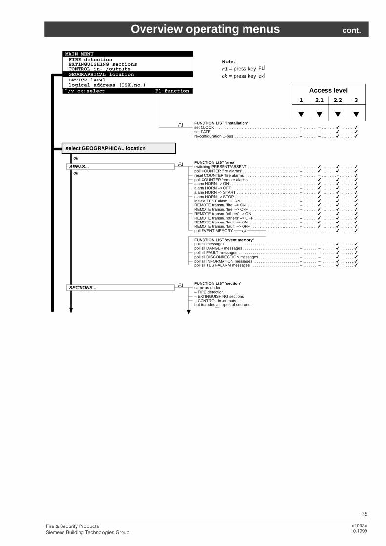
e1033e10.1999
35
Fire & Security Products
Siemens Building Technologies Group
Overview operating menus cont.
FUNCTION LIST ’area’switching PRESENT/ABSENT – � � �. . . . . . . . . . . . . . . . . . . . . . . . . . . . . . . . . . . . . . . . . . . . . . . . . . . . . poll COUNTER ’fire alarms’ – � � �. . . . . . . . . . . . . . . . . . . . . . . . . . . . . . . . . . . . . . . . . . . . . . . . . . . . . . . . reset COUNTER ’fire alarms’ – – – �. . . . . . . . . . . . . . . . . . . . . . . . . . . . . . . . . . . . . . . . . . . . . . . . . . . . . . . . . poll COUNTER ’remote alarms’ – � � �. . . . . . . . . . . . . . . . . . . . . . . . . . . . . . . . . . . . . . . . . . . . . . . . . . . . alarm HORN –> ON – � � �. . . . . . . . . . . . . . . . . . . . . . . . . . . . . . . . . . . . . . . . . . . . . . . . . . . . . . . . . . . . . . . . alarm HORN –> OFF – � � �. . . . . . . . . . . . . . . . . . . . . . . . . . . . . . . . . . . . . . . . . . . . . . . . . . . . . . . . . . . . . . alarm HORN –> START – � � �. . . . . . . . . . . . . . . . . . . . . . . . . . . . . . . . . . . . . . . . . . . . . . . . . . . . . . . . . . . . alarm HORN –> STOP – � � �. . . . . . . . . . . . . . . . . . . . . . . . . . . . . . . . . . . . . . . . . . . . . . . . . . . . . . . . . . . . . initiate TEST alarm HORN – � � �. . . . . . . . . . . . . . . . . . . . . . . . . . . . . . . . . . . . . . . . . . . . . . . . . . . . . . . . . REMOTE transm. ’fire’ –> ON – � � �. . . . . . . . . . . . . . . . . . . . . . . . . . . . . . . . . . . . . . . . . . . . . . . . . . . . . REMOTE transm. ’fire’ –> OFF – � � �. . . . . . . . . . . . . . . . . . . . . . . . . . . . . . . . . . . . . . . . . . . . . . . . . . . . REMOTE transm. ’others’ –> ON – � � �. . . . . . . . . . . . . . . . . . . . . . . . . . . . . . . . . . . . . . . . . . . . . . . . . . REMOTE transm. ’others’ –> OFF – � � �. . . . . . . . . . . . . . . . . . . . . . . . . . . . . . . . . . . . . . . . . . . . . . . . . REMOTE transm. ’fault’ –> ON – � � �. . . . . . . . . . . . . . . . . . . . . . . . . . . . . . . . . . . . . . . . . . . . . . . . . . . . REMOTE transm. ’fault’ –> OFF – � � �. . . . . . . . . . . . . . . . . . . . . . . . . . . . . . . . . . . . . . . . . . . . . . . . . . . poll EVENT MEMORY – – � �. . . . . . . . . . . . . . . . . . . . . . . . . . . . . . . . . . . . . . . . . . . . . . . . . . . . . . . . . . . . . .
FUNCTION LIST ’section’same as under– FIRE detection– EXTINGUISHING sections– CONTROL in-/outputsbut includes all types of sections
AREAS...
ok
ok
F1
F1
F1
Note:F1 = press key ok = press key
FUNCTION LIST ’installation’set CLOCK – – � �. . . . . . . . . . . . . . . . . . . . . . . . . . . . . . . . . . . . . . . . . . . . . . . . . . . . . . . . . . . . . . . . . . . . . . . . . . set DATE – – � �. . . . . . . . . . . . . . . . . . . . . . . . . . . . . . . . . . . . . . . . . . . . . . . . . . . . . . . . . . . . . . . . . . . . . . . . . . . . re-configuration C-bus – – � �. . . . . . . . . . . . . . . . . . . . . . . . . . . . . . . . . . . . . . . . . . . . . . . . . . . . . . . . . . . . . .
1 2.1 2.2 3
Access level
� � � �
FUNCTION LIST ’event memory’poll all messages – – � �. . . . . . . . . . . . . . . . . . . . . . . . . . . . . . . . . . . . . . . . . . . . . . . . . . . . . . . . . poll all DANGER messages – – � �. . . . . . . . . . . . . . . . . . . . . . . . . . . . . . . . . . . . . . . . . . . . . . . . poll all FAULT messages – – � �. . . . . . . . . . . . . . . . . . . . . . . . . . . . . . . . . . . . . . . . . . . . . . . . . . poll all DISCONNECTION messages – – � �. . . . . . . . . . . . . . . . . . . . . . . . . . . . . . . . . . . . . . . poll all INFORMATION messages – – � �. . . . . . . . . . . . . . . . . . . . . . . . . . . . . . . . . . . . . . . . . . poll all TEST-ALARM messages – – � �. . . . . . . . . . . . . . . . . . . . . . . . . . . . . . . . . . . . . . . . . . .
ok
F1
ok
SECTIONS...
select GEOGRAPHICAL location
MAIN MENUFIRE detectionEXTINGUISHING sectionsCONTROL in- /outputsGEOGRAPHICAL locationDEVICE levellogical address (CSX.no.)
^/v ok:select F1:function

e1033e10.1999
36
Fire & Security Products
Siemens Building Technologies Group
Overview operating menus cont.
FUNCTION LIST ’control unit’poll INFORMATION control unit – – � �. . . . . . . . . . . . . . . . . . . . . . . . . . . . . . . . . . . . . . . . . . . . . . . . . . . . . poll EVENT MEMORY (control unit) – – � �. . . . . . . . . . . . . . . . . . . . . . . . . . . . . . . . . . . . . . . . . . . . . . . . set PRINTER (control unit) –> OFF – – � �. . . . . . . . . . . . . . . . . . . . . . . . . . . . . . . . . . . . . . . . . . . . . . . . . set PRINTER (control unit) –> ON – – � �. . . . . . . . . . . . . . . . . . . . . . . . . . . . . . . . . . . . . . . . . . . . . . . . . . initiate PRINTER-TEST (control unit) – – � �. . . . . . . . . . . . . . . . . . . . . . . . . . . . . . . . . . . . . . . . . . . . . . .
FUNCTION LIST ’terminal’poll INFORMATION ’terminal’ – – � �. . . . . . . . . . . . . . . . . . . . . . . . . . . . . . . . . . . . . . . . . . . . . . . . . . . . . . . initiate LAMP TEST – � � �. . . . . . . . . . . . . . . . . . . . . . . . . . . . . . . . . . . . . . . . . . . . . . . . . . . . . . . . . . . . . . . . set contrast of DISPLAY – – � �. . . . . . . . . . . . . . . . . . . . . . . . . . . . . . . . . . . . . . . . . . . . . . . . . . . . . . . . . . . . set sound level of BUZZER – – � �. . . . . . . . . . . . . . . . . . . . . . . . . . . . . . . . . . . . . . . . . . . . . . . . . . . . . . . . . poll EVENT MEMORY (terminal) – � � �. . . . . . . . . . . . . . . . . . . . . . . . . . . . . . . . . . . . . . . . . . . . . . . . . . . set PRINTER (terminal) –> OFF – – � �. . . . . . . . . . . . . . . . . . . . . . . . . . . . . . . . . . . . . . . . . . . . . . . . . . . . set PRINTER (terminal) –> ON – – � �. . . . . . . . . . . . . . . . . . . . . . . . . . . . . . . . . . . . . . . . . . . . . . . . . . . . . initiate PRINTER-TEST (terminal) – – � �. . . . . . . . . . . . . . . . . . . . . . . . . . . . . . . . . . . . . . . . . . . . . . . . . .
FUNCTION LIST ’function unit’poll INFORMATION ’function unit’ – � � �. . . . . . . . . . . . . . . . . . . . . . . . . . . . . . . . . . . . . . . . . . . . . . . . .
FUNCTION LIST ’function unit’poll INFORMATION ’function unit’ – � � �. . . . . . . . . . . . . . . . . . . . . . . . . . . . . . . . . . . . . . . . . . . . . . . . .
FUNCTION LIST ’function unit’poll INFORMATION ’function unit’ – � � �. . . . . . . . . . . . . . . . . . . . . . . . . . . . . . . . . . . . . . . . . . . . . . . . . initiate BATTERY LOAD TEST – – � �. . . . . . . . . . . . . . . . . . . . . . . . . . . . . . . . . . . . . . . . . . . . . . . . . . . . . .
FUNCTION LIST ’function unit’poll INFORMATION ’function unit’ – � � �. . . . . . . . . . . . . . . . . . . . . . . . . . . . . . . . . . . . . . . . . . . . . . . . .
FUNCTION LIST ’device’poll INFORMATION ’device’ – – � �. . . . . . . . . . . . . . . . . . . . . . . . . . . . . . . . . . . . . . . . . . . . . . . . . . . . . . . .
DEVICE level
power supply supervision
I�/�O’s of terminal unit B3Q460/80
keys and indicators of CT11 panel
terminal CT11 (CI11)
control unit CC11
ok
F1
F1
F1
F1
F1
F1
ok
ok
ok
okI/O’s of control unit E3X100
(device)
FUNCTION LIST ’event memory’poll all messagespoll all DANGER messagespoll all FAULT messagespoll all DISCONNECTION messagespoll all INFORMATION messagespoll all TEST-ALARM messages
ok
FUNCTION LIST ’function unit’poll INFORMATION ’function unit’ – � � �. . . . . . . . . . . . . . . . . . . . . . . . . . . . . . . . . . . . . . . . . . . . . . . . . FBA panel F1
FUNCTION LIST ’event memory’poll all messagespoll all DANGER messagespoll all FAULT messagespoll all DISCONNECTION messagespoll all INFORMATION messagespoll all TEST-ALARM messages
FUNCTION LIST ’function unit’poll INFORMATION ’function unit’ – � � �. . . . . . . . . . . . . . . . . . . . . . . . . . . . . . . . . . . . . . . . . . . . . . . . . initiate BATTERY LOAD TEST – – � �. . . . . . . . . . . . . . . . . . . . . . . . . . . . . . . . . . . . . . . . . . . . . . . . . . . . . .
power supply supervision F1
FUNCTION LIST ’function unit’poll INFORMATION ’function unit’ – � � �. . . . . . . . . . . . . . . . . . . . . . . . . . . . . . . . . . . . . . . . . . . . . . . . . ...
FUNCTION LIST ’device’poll INFORMATION ’device’ – – � �. . . . . . . . . . . . . . . . . . . . . . . . . . . . . . . . . . . . . . . . . . . . . . . . . . . . . . . . ...
F1
F1
ok(function unit)
(device)
1 2.1 2.2 3
Access level
� � � �
Note:F1 = press key ok = press key
F1
ok
MAIN MENUFIRE detectionEXTINGUISHING sectionsCONTROL in- /outputsGEOGRAPHICAL locationDEVICE levellogical address (CSX.no.)
^/v ok:select F1:function

e1033e10.1999
37
Fire & Security Products
Siemens Building Technologies Group
Overview operating menus cont.
Note:ok = press key
logical address (CSX. no.)
ok
1 2.1 2.2 3
Access level
� � � �
area / section / zone / element – � � �. . . . . . . . . . . . . . . . . . . . . . . . . . . . . . . . . . . . . . . . . . . . . . . . . . . . .
ok
MAIN MENUFIRE detectionEXTINGUISHING sectionsCONTROL in- /outputsGEOGRAPHICAL locationDEVICE levellogical address (CSX.no.)
^/v ok:select F1:function

e1033e10.1999
38
Fire & Security Products
Siemens Building Technologies Group
Notes

e1033e10.1999
39
Fire & Security Products
Siemens Building Technologies Group
Notes

Back10.1999
40
Fire & Security Products
Siemens Building Technologies Group
Document no.
Edition
e1033e
10.1999
Siemens Building Technologies AG
CH�8708 Männedorf
Alte Landstrasse 411
Tel.
Fax
www.cerberus.ch
+41 1 − 922 61 11
+41 1 − 922 64 50
Manual CS11.2
Section 7