alarm controlled light switch
DESCRIPTION
Alarm Controlled Light SwitchTRANSCRIPT

ALARM CONTROLLED LIGHT SWITCH
GUIDED BY,ER. ASHWIN P.V

GROUP MEMBERS
• Abhirami R• Akhila Sebastian• Abidha Shanavas• Jenita Ann Mathews• Jisha Raju• Reshma Jolly• Rijoe Chacko Mathew

INTRODUCTION
• On a typical workday morning, if you’re like most people, you don’t wake up naturally. Instead, the ring of an alarm clock probably jerks you out of sleep. Depending on when you went to bed, what day of the week it is, and how deeply you were sleeping, you may not understand where you are, or why there’s an infernal chiming sound. Then you throw out your arm and hit the snooze button, silencing the noise for at least a few moments. Just another couple of minutes, you think. Then maybe a few minutes more.• In those early waking minutes, our memory, reaction time, ability to
perform basic mathematical tasks, and alertness and attention all suffer. Even simple tasks, like finding and turning on the light switch, become far more complicated. Here lies the relevance of this project. A light-up alarm completely change life since the light automatically turns on we get distracted from sleep an it becomes more easy to wake up.

COMPONENTS REQUIRED
• Sound detector sensor module• Resistors 1K ,10K• Transistor BC337• 5V Relay• 9V Battery• 7805 Regulation IC• Lamp
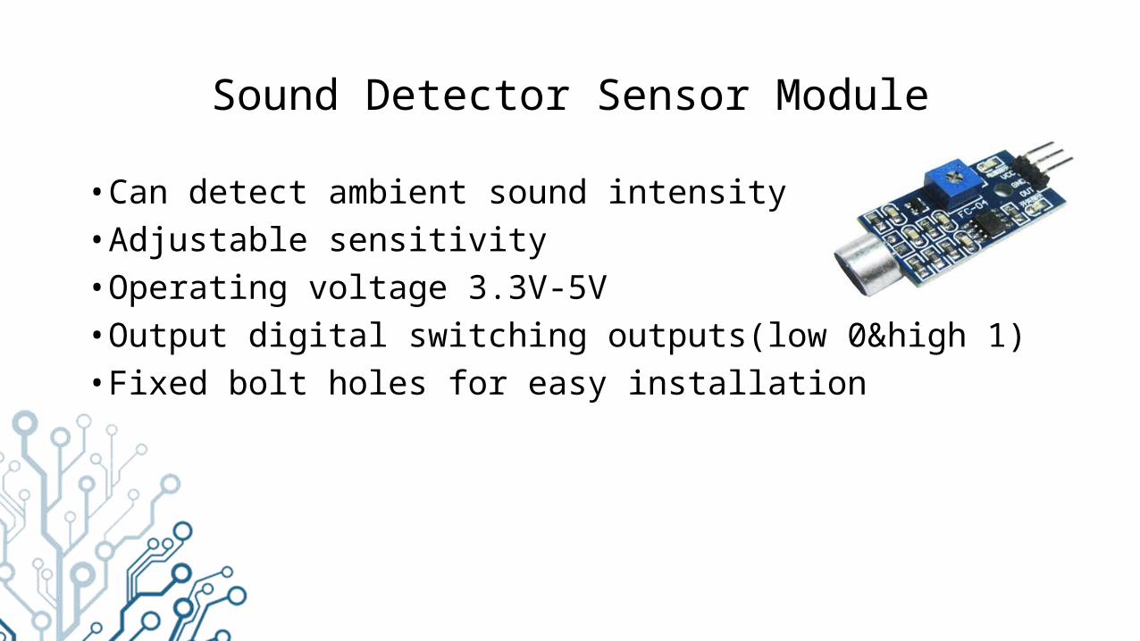
Sound Detector Sensor Module
• Can detect ambient sound intensity• Adjustable sensitivity• Operating voltage 3.3V-5V• Output digital switching outputs(low 0&high 1)• Fixed bolt holes for easy installation

Relay
• A relay is an electrically operated switch. Many relays use an electromagnet to mechanically operate a switch. Relays are used where it is necessary to control a circuit by a low-power signal or where several circuits must be controlled by one signal

Transistor BC337
• This device is designed for use as general purpose amplifiers and switches requiring collector currents to 500 mA.

CIRCUIT DIAGRAM

ALARM
Sound from Alarm
Sound DetectorSensor Relay Switch
Lamp
BLOCK DIAGRAM

WORKING
• Sound detecting sensor produces an output of +5 Volt when it detects sound and its output remains at zero state If no sound is detected. • When the alarm rings the sound detecting module senses the sound and
produces an output of +5 Volt. This output provides a base drive to the BJT switching circuit. Consequently the relay circuit turns on and current starts flowing through the relay coil.• Due to the flow of current through the coil switching takes place. The light
switch which was normally open becomes conditionally closed. As a result the light turns on. When the alarm is switched off sensor fails to detect any sound. Therefore sensor output moves to zero state. • Thus the relay comes back to the normal state and light turns off.

CONCLUSION
• Research shows that the healthiest way to wake up is along with the sun rising and the world gradually becoming lighter. And there’s the premise of a wake-up light alarm. • A wake up light guides you gently out of a deep sleep phase towards
awakening. They work because your eyes register light exposure even when they are closed. • Early in the morning when you are still asleep your biological clock
senses low intensity light. • Wake up lights gently wake you up providing you with more energy,
productivity, and a better mood during the day.