aki suittio testing iec 61850 in multi-vendor …...mukaan. areva t&d oy:n micom-tuoteperheestä...
TRANSCRIPT

AKI SUITTIO TESTING IEC 61850 IN MULTI-VENDOR SUBSTATION AUTOMATION SYSTEM Master’s Thesis
Examiner: Professor Pekka Verho Examiner and topic approved in the Department of Electrical Energy Engineering Council meeting on third of March 2010
II
TIIVISTELMÄ TAMPEREEN TEKNILLINEN YLIOPISTO Sähkötekniikan koulutusohjelma SUITTIO, AKI: IEC 61850 sähköasema-automaatio järjestelmän testaus Diplomityö, 69 sivua, 9 liitesivua Toukokuu 2010 Pääaine: Sähkövoimatekniikka Tarkastaja: professori Pekka Verho Avainsanat: IEC 61850, sähköasema-automaatio, IED, GOOSE, yhteensopivuus Nopeasti kehittyvässä maailmassa myös sähköasema-automaation vaatimukset ovat
kasvussa. Sähköasema-automaation kehitykseen vaikuttavat merkittävästi kasvavat
sähkön laadun vaatimukset sekä sähköntuotannon rakenteiden muuttuminen kohti
hajautettua sähköntuotantoa. Sähköntuotannon muutoksia vauhdittavat ilmastonmuutos-
skenaariot, joiden vuoksi erityisesti tuulivoiman osuus sähköntuotannosta tulee rajusti
lisääntymään. Sähköyhtiöillä sähkön toimituksen keskeytyskustannukset kasvavat,
minkä takia sähköverkkoyhtiöt haluavat jatkossa vähentää keskeytyksistä syntyviä
menetyksiä ja parantaa sähkön laatua. Näiden asioiden solmupisteessä ja keskeisessä
roolissa on sähköasema-automaatio.
Uusi sähköaseman sisäisen tietoliikenteen standardi IEC 61850 mahdollistaa
uudenlaisen sähköasema-automaation kehittymisen. Aikaisemmin sähköasemien
sisäinen tietoliikenne on perustunut laitevalmistajien itse kehittämiin protokolliin. Tästä
syystä eri laitevalmistajien laitteiden keskinäinen kommunikaatio ei ole onnistunut
ilman protokollamuuntimia, joiden käyttö on ollut hankalaa. Käytännössä sähköaseman
kommunikoiva laitteisto on aikaisemmin toteutettu kokonaan yhden laitevalmistajan
laitteilla. Tämä on johtanut siihen, että markkinoita ovat hallinneet isot laitevalmistajat,
mikä on puolestaan vaikuttanut sähköasema-automaation tekniseen kehittymiseen. IEC
61850 on universaali standardi, joka on toteutettu eri standardisointilaitosten ja
laitevalmistajien yhteistyönä. Se on saanut osakseen kiinnostusta ja on jo vahvasti
mukana esimerkiksi ´Smart Grids´ -suunnitelmissa.
IEC 61850 -standardissa on monia asioita, jotka tekevät siitä aikaisempia
sähköasemakommunikaatiostandardeja edistyneemmän. Standardin objektimalli on yksi
standardin suurimmista eduista. Se antaa jokaiselle tietopisteelle yksilöllisen nimen.
Tietopisteiden nimet toimivat yksilöllisinä osoitteina, joista lukija tunnistaa heti tiedon
fyysisen lähteen ilman suurta määrää objektien ulkoa opettelua. Vanhemmat standardit
ovat käyttäneet hyväksi indeksinumeroita, jotka eivät kerro mitään tietopisteen
sisällöstä. Toinen standardin suurimmista eduista on horisontaalinen GOOSE-viestintä,
jonka avulla esimerkiksi sähköaseman suojareleet pystyvät kommunikoimaan suoraan
keskenään. GOOSE-kommunikaation avulla voidaan esimerkiksi parantaa
selektiivisyyttä ja lyhentää katkaisijan laukaisuaikoja.
Tämän diplomityön tavoitteena oli testata eri IEC 61850 -standardiin
perustuvien laitteiden yhteentoimivuutta, luoda samalla esimerkkikonfiguraatiot

III
valituille laitteille sekä antaa UTU Elec Oy:lle valmiuksia toimia IEC 61850 -standardin
mukaisten järjestelmien toimittajana. Diplomityön teettäjinä toimivat UTU Elec Oy
sekä Areva T&D Oy. Työn keskeisin osa koostuu Areva T&D Oy:n asematietokoneen
avulla toteutetusta demo-järjestelmästä, jossa asematietokoneeseen liitettiin IEC 61850
väylän kautta eri laitevalmistajien suojausreleitä ja yksi jänniteregulaattori. Lisäksi
työssä arvioitiin suppeasti IEC 61850 -standardin hyötyjä tuulivoimasovellutuksissa.
Demojärjestelmä suunniteltiin, ohjelmoitiin sekä rakennettiin pääasiallisesti UTU Elec
Oy:n toimitiloissa Ulvilassa. Areva T&D Oy:n toimitiloissa Frankfurtissa suoritettiin
Arevan asematietokoneen ohjelmointikoulutus sekä osa demo-järjestelmän
ohjelmoinnista. Muita järjestelmän laitteita varten ei hankittu erillistä koulutusta, koska
sitä ei havaittu tarpeelliseksi.
Tämä työ sisältää myös teoriaosuuden, joka käsittelee IEC 61850 -standardia.
Standardin sisältö on pyritty esittämään mahdollisimman selkeästi ja kattavasti, jotta sen
avulla voisi mahdollisimman hyvin sisäistää standardin teorian sekä taustalla olevat
periaatteet. Teorian ohessa käsitellään myös standardin etuja ja tulevaisuuden
mahdollisuuksia. Aluksi teoriaosuudessa käsitellään standardin taustalla olevia teorioita
yleisellä tasolla ja esitellään standardin historiaa. Lisäksi teoriassa käsitellään standardin
keskeisimpiä osa-alueita: objektimalli, MMS-kommunikaatio, GOOSE-kommunikaatio
ja fyysistä Ethernet-kommunikaatiota koskevat osa-alueet. Työ sisältää myös erillisen
osa-alueen, joka käsittelee suppeasti IEC 61850 ja IEC 61400-25 -standardeja
tuulivoimasovellutuksissa.
IEC 61850 -demojärjestelmän laitteet valittiin työn rahoittajien tarpeiden
mukaan. Areva T&D Oy:n MiCOM-tuoteperheestä valittiin C264-asematietokone sekä
P139-suojarele. Suojareleet valittiin sen mukaan, miten relevantteja ne ovat Suomen
markkinoilla, jotta UTU Elec Oy hyötyisi demo-järjestelmästä mahdollisimman paljon.
Jänniteregulaattori valikoitui järjestelmään sen mukaan, mitä Areva suositteli
käytettäväksi C264-asematietokoneen kanssa. Arevan C264-asematietokoneen kanssa
demo-järjestelmään liitettiin ABB Oy:n REF 615 - ja VAMP Oy:n VAMP52 -
suojareleet sekä A. Eberle GmbH & Co:n REG-DA jänniteregulaattori. Järjestelmän
kaikki laitteet laitettiin esille helposti liikuteltavaan puiseen laatikkoon. SCADA-
simulaattori ohjelmistoa ajettiin kannettavasta tietokoneesta, joka sijoitettiin puulaatikon
päälle.
Demojärjestelmän saattaminen alustavien suunnitelmien mukaiseksi tiedettiin
haasteelliseksi jo ennen konfiguroinnin aloittamista, koska lähteitä lukemalla saatiin
hyvä käsitys käytännön sovellutuksien yhteensopivuusongelmista. IEC 61850
yhteensopivuus on esisijaisesti riippuvainen asematietokoneen sekä releiden ja
jänniteregulaattorin välisestä kommunikaatiosta. Koska C264:n, P139:n ja REG-DA:n
välinen yhteensopivuus on Arevan testaama, mainittujen laitteiden kanssa ei
yhteensopivuusongelmia esiintynyt. Koska kaikkien laitteiden keskinäistä toimivuutta ei
ollut testattu, ongelmia oli odotettavissa. Kaikki laitteet saatiin kuitenkin liitettyä demo-
järjestelmään, mutta ihan kaikkia ongelmia ei saatu ratkaistua, koska konfigurointiin
käytettävä aika oli rajallinen.

IV
Suurin osa ongelmista aiheutui pääasiassa konfigurointiohjelmien välillä
vaihdettavista SCL-tiedostoista. SCL (Substation Configuration Language) on yleiseen
XML (Extensible Markup Language) -kieleen perustuva kieli, joka mahdollistaa eri
ohjelmistojen käytön sähköasema-automaatiojärjestelmän konfiguroinnissa. Standardi
määrittelee SCL-kieliset konfigurointitiedostot, jotka edustavat käytännön
konfigurointityön eri vaiheita. Demo-järjestelmän konfiguroinnissa ongelmia
aiheuttivat eri laitevalmistajien SCL-kieliset ICD (IED Capability Description) -
tiedostot, koska muita SCL-tiedostoja ei ollut juurikaan tarvetta käyttää. Ongelmat
johtuivat pienistä eroavaisuuksista ICD-tiedostoissa ja siitä, miten asematietokoneen
konfigurointiohjelma kulutti eri laitevalmistajien ICD-tiedostoja.
Demojärjestelmä saatiin toimimaan tiukassa aikataulussa, vaikka järjestelmässä
oli laitteita neljältä eri laitevalmistajalta. Niiden laitteiden kanssa, jotka olivat ennestään
Arevan testaamia, ei esiintynyt kommunikaatio-ongelmia. Kokemuksen karttuessa
järjestelmien saattaminen toimintakuntoon nopeutunee huomattavasti, koska demo-
järjestelmää konfiguroitaessa aikaa kului suhteellisen paljon ohjelmistojen toiminnan
sekä IEC 61850 -standardin periaatteiden opettelemiseen. Demolaitteistokin osoittaa,
että eri laitevalmistajien laitteiden välisessä yhteensopivuudessa on ongelmia, mutta
ongelmat ovat suhteellisen pieniä ja ovat useasti korjattavissa pienellä vaivalla.
Vaikka IEC 61850 -standardin edut ovat tiedossa, on standardin erilaisuus
verrattuna vanhempiin standardeihin osoittautunut ainakin pieneksi esteeksi standardin
yleistymiselle. Standardi ei ole aukoton ja siitä on haluttu mahdollisimman vähän
kehittymistä rajoittava. Koska standardi antaa laitevalmistajille tilaa käytännön
toteutuksille, tulee sovellutuksiin eroavaisuuksia, jotka aiheuttavat
yhteensopivuusongelmia. Standardi on vielä melko uusi siinä suhteessa, että
sähköasema-automaatiolaitteiston laskennallinen elinikä on melko pitkä ja laitteita
uusitaan suhteellisen harvoin. Koska sähköautomaatiojärjestelmät ovat suuria
hankintoja, kaikki eivät halua investoida tekniikkaan, joka on vielä kesken ja jonka
käyttäminen on vaikeaa. Kaikille aloille IEC 61850 -standardi ei välttämättä edes tuo
mitään, millä olisi lisäarvoa verrattuna vanhempiin järjestelmiin. Jotta IEC 61850
standardi lähtisi yleistymään siinä tahdissa kuin sen olettaisi yleistyvän, täytyisi
standardin mukaisten laitteiden yhteensopivuuden eteen tehdä vielä töitä. Joko
laitevalmistajien tulisi testata laitteidensa toimivuutta muiden laitevalmistajien laitteiden
kanssa enemmän ja vaihtaa testaustietoa keskenään, tai yhteensopivuusongelmista tulisi
julkaista standardi, jossa ratkaisuista sovittaisiin laitevalmistajien kesken.

V
ABSTRACT TAMPERE UNIVERSITY OF TECHNOLOGY Master’s Degree Programme in Information Technology SUITTIO, AKI: Testing IEC 61850 in multi-vendor substation automation system Master of Science Thesis, 69 pages, 9 Appendix pages May 2010 Major: Power Systems Examiner: Professor Pekka Verho Keywords: IEC 61850, Substation automation, multi-vendor, IED, GOOSE, interoperability In the quickly evolving world the requirements for substation automation is increasing.
The most significant factors in the progress of substation automation are the demands
for better quality electricity supply and the evolution of the electric generation towards
decentralized generation. The changes in electric generation are driven by the scenarios
of global warming. Because of the scenarios, especially the volume of wind power
plants is increasing drastically in the electric generation segment. The costs for
interruption in electricity supply is increasing and the electricity distribution companies
wants reduce interruption costs and offer better quality electricity. In the nodal point of
these matters is the substation automation.
The new standard IEC 61850 for communication in substation automation
enables a new kind of solutions in substation automation. Earlier the communication in
substations has been based on various manufacturers self developed protocols. For this
reason the communication between different manufacturers devices has not been
possible without protocol converters, which are difficult to use. In practise the working
installations have been actualised with devices from a single manufacturers selection.
The markets have dominated by large manufacturers that have a full selection of
substation automation devices. IEC 61850 is a universal standard, which has been
developed in co-operation with several standardisation organizations and manufacturers.
The standard has received lot of interest and already is strongly in future ‘Smart grid’
plans.
The objectives of this master’s thesis was to test the interoperability of
substation devices based on IEC 61850 and in the process create example configurations
from the selected devices for UTU Elec Oy. This work was funded by UTU Elec Oy
and Areva T&D Oy. A demo-system was built with Areva T&D Oy’s station computer,
with different manufacturers protective relays and one voltage regulator.
Communication between the devices was based on IEC 61850. This paper will also
include a narrow evaluation of the benefits of the IEC 61850 in wind power plant
solutions. The demo-system was built mainly in Ulvila at UTU Elec Oy’s office and
during couple weeks in Areva T&D Oy’s office at Frankfurt am Main.

VI
PREFACE
This master thesis presents results of testing substation automation system implemented
with IEC 61850. The automation components for the testing have been selected from
various vendors. The financiers for this thesis are UTU Elec Oy and Areva T&D Oy.
The goal of this work is to prepare UTU Elec Oy towards offering fully working
substation systems with IEC 61850. The multi-vendor demo-system was built mainly in
Ulvila at UTU Elec Oy’s office and at Areva T&D Oy’s office at Frankfurt am Main.
The main instructors for this work were Pasi Lauri from UTU Elec and Ari Pentikäinen
and Stefan Scharf from Areva T&D.

VII
Content
Tiivistelmä ........................................................................................................................ii
Abstract .............................................................................................................................v
Preface..............................................................................................................................vi
Glossary ...........................................................................................................................ix
1. Introduction ...............................................................................................................1
2. An overview of the new substation standard IEC 61850..........................................2
2.1. IEC 61850 purpose and benefits ....................................................................2
2.2. IEC 61850 background...................................................................................3
2.3. IEC 61850 content..........................................................................................4
2.4. IED modelling ................................................................................................5
2.5. Logical node concept......................................................................................9
2.6. IEC 61850 communication protocols...........................................................10
2.7. Physical communication...............................................................................11
2.8. ACSI (Abstract Communication Service Interface).....................................14
2.9. MMS (Manufacturing messaging specification) ..........................................15
2.10. GSSE, GOOSE and Sampled Values ...........................................................17
2.11. Substation bus topologies.............................................................................19
2.12. Time Synchronization ..................................................................................21
2.13. Communication performance requirements .................................................22
2.14. System configuration....................................................................................24
2.15. Retransmission scheme ................................................................................27
2.16. System reliability and redundancy ...............................................................29
2.17. Security.........................................................................................................30
3. IEC 61850 and wind power ....................................................................................32
3.1. Evaluation perspectives ................................................................................32
3.2. IEC 61400-25 and IEC 61850 ......................................................................32
3.3. The impact of the new standards ..................................................................34
4. IEC 61850 demo system .........................................................................................36
4.1. IEC 61850 system configuration..................................................................36
4.2. Objectives of the demo.................................................................................37
4.3. Demo equipment ..........................................................................................37
4.4. Additional demo equipment .........................................................................39
4.5. Demo system communication design...........................................................40
4.6. PACiS SCE...................................................................................................41
4.7. Bay level IED configuration tools................................................................45
4.8. MiCOM S1 Studio........................................................................................45
4.9. Vampset........................................................................................................46
4.10. WinConfig GOOSE light .............................................................................48
4.11. PCM600 and CCT600..................................................................................49
4.12. Other useful tools .........................................................................................51

VIII
5. Experiences from testing multi-vendor system.......................................................52
5.1. Configuration experiences............................................................................52
5.2. Static or dynamic ICD-file ...........................................................................53
5.3. The use of generic I/O’s ...............................................................................53
5.4. Goose mapping.............................................................................................54
5.5. The debug schema ........................................................................................55
6. Conclusion ..............................................................................................................56
References .......................................................................................................................57
Appendix A .....................................................................................................................61
Appendix B .....................................................................................................................66

IX
GLOSSARY
IEC International Electrotechnical Commission
IED Intelligent Electronic Device
SAS Substation Automation Systems
GOOSE Generic Object Oriented Substation Event
NCIT Non-Conventional Instrument Transformer
CT Current Transformer
VT Voltage Transformer
MU Merging Unit
SCL Substation Configuration Language
EPRI Electric Power Research Institute
IEEE The Institute of Electrical and Electronics Engineering
UCA Utility Communications Architecture
UCA 2.0 Utility Communications Architecture Version two
MMS Manufacturing Message Specification
ACSI Abstract Communication Service Interface
ISO International Organization for Standardization
IP-address Internet Protocol address
PICOM Piece of Information for COMmunication
TCP/IP Transmission Control Protocol / Internet Protocol
VMD Virtual Manufacturing Device
LAN Local Area Network
SCSM Specific Communication Service Mapping
GSE Generic Substation Event
GSSE Generic Substation State Event
CSMA/CD Carrier Sense Multiple Access with Collision Detection
RSTP Rapid Spanning Tree Protocol
GPS Global Positioning System
SNTP Simple Network Time Protocol
IRIG-B Inter-Range Instrumentation Group time code B
PTP Precision Time Control
PnP Plug and play
XML v.1.0 Extensible Markup Language version 1.0
ICD IED Capability Describtion
CID Configured IED Description
SCD Substation Configuration Description
SSD System Specification Description
VPN Virtual Private Network
IDS Intrusion Detection System
TCD Turbine Controller Device
CMD Condition Monitoring Device
1
1. INTRODUCTION
IEC 61850 is relatively new standard, but already it has been considered to
revolutionize the electricity distribution automation world wide. The new standard has
already been demonstrated successfully in several working substations. The IEC 61850
has been considered to replace, not only the substation communication standards, but
communication to the control room as well. Because the standard brings a lot new
practices and concept to the substation automation systems, vast a mount of testing must
be done before full substation automation system with IEC 61850 will become
common.
The IEC 61850 is an international standard, which has been developed with
major manufacturers. The standards main purpose is to bring new common
communication rules to the substation automation, which would replace older
communication standards. The communication rules are set by defining the station bus.
The station bus is defined by giving the data points comprehensive names, which
describe the data points. The standard defines data points in several levels and the most
important level is the logical node level. The standard also defines sets of services,
which operate on the data. More detailed description about the standard is included in
the theory section of this paper in chapter 2.
This thesis constructs from four different parts. The first part introduces the IEC
61850 standard, opens the concepts and introduces some problems and possibilities,
which have emerged during the reading of source material. Second part introduces IEC
61850 and IEC 61400-25 in wind power systems and the next two parts concern the IEC
61850 demo-system. The demo-system is a multi-vendor substation automation system,
which consists of thee protective relays, one voltage regulator and one bay computer.
The first section, concerning the demo-system, describes the demo-system, software and
introduces the software and configuration problems with the software. The second part
introduces the difficulties and problems, which emerged during the configuration work.

2. AN OVERVIEW OF THE NEW SUBSTATION STANDARD IEC 61850
2.1. IEC 61850 purpose and benefits
The development in electric distribution substation automation has not been particularly
fast since the systems have to be highly reliable and the old systems have offered just
that. Since the mixing of several communication standards is difficult, single universal
standard is needed. The substation standard IEC 61850 has already been proven to be
reliable and suitable for the purpose.
Since the emergence of the microprocessor relays, manufacturers have had their
own protocols for communication between IED’s (Intelligent Electronic Device).
Because of the different protocols in multi-manufacturer SAS (Substation Automation
Systems), costly protocol converters have to be used. This solution creates large
amounts of engineering work for system designing, testing and etc. All these reasons
have generated needs for a single universal protocol that satisfies both manufacturers
and the end users. Interoperability between different manufacturers IED’s is a major
factor in developing substation automation. With interoperability all vendors are apple
to provide manufacturer independent system with flexible extensibility and
functionality. The main purpose of the new standard is that products from different
vendors can easily be integrated to one substation infrastructure. This is done by
defining the station bus. [1]
Distribution companies are facing more and more pressure to provide better
quality electricity and one way to do that is to increase data flow and obtain larger
quantities of data from substations in real time. Real time data enables new kind of
calculations for substation monitoring, equipment maintenance, switching schemas and
power flow. IEC 61850 standard is mapped over the ‘state of art’ communication
technology, which enables fast and reliable data transfer. Advanced functionality and
data transfer methods are one step closer to future visions ´Smart Grids´.
IEC 61850 standard has been created to be functionally flexible and expandable.
The standard uses information technology, which support variety of services with
selection of performance requirements. Fast communication between individual IED’s
enables bay to bay communication. With bay to bay communication for example
interlocking can be executed trough communication lines. [1] With IEC 61850 IED’s
are able to communicate with each others, by publishing and subscribing GOOSE
messages. More detailed description about GOOSE messaging in chapter 2.10.

3
IED’s are microprocessor-based devices and microprocessors are becoming
more powerful. One substation has several IED’s and in order to substation automation
works as automated, IED’s have to be able to communicate with each other and in case
of anomalies IED’s should work intelligently together.
One advantage with the IEC 61850 is that it supports NCIT (Non-Conventional
Instrument Transformer) technology. NCIT technology has been developed more in few
years than in fifteen years before the IEC 61850. The NCIT technology has such
benefits compared to conventional CT’s (Current Transformer) and VT’s (Voltage
Transformer) as transient elimination, improved safety and accuracy and reduced
wiring. Some of the NCIT devices are fairly ready and with a MU (Merging Unit),
introduces in the IEC 61850, the implementation is not an issue. [2] The merging units
and sampled value transfer is introduced in chapter 2.7.
The IEC 61850 standard has been designed to cover and map all information
needed for automation in electric substations. All individual data points have a unique
name that simultaneously describes the data point in a way that it can be easily
understood. The standard strives towards more open systems by mapping the
communication and setting data points. The future vision is that all IED’s which fully
supports the IEC 61850 can be configured by third party configuration tool or that the
IED’s can even configure themselves when plugged into a working system.
The organization of all data in IED’s is in major role in IEC 61850. The earlier
protocols did not specify how the data should be organized. They only defined how the
data should be transmitted through the wire. The earlier solutions generate large
amounts of configuration work and in multi-protocol systems the time and effort put in
configuration is multiplied. IEC 61850 reduces configuration work by mapping data so
that all devices whit IEC 61850 should organize data at the same way. By mapping the
data consistently IED’s should be apple to configure themselves. Such interoperability
still lies in the future and mean while the interoperability is achieved by transferring
configuration files between IED configuration tools. More information about SCL and
IED configuration is in chapter 2.14.
2.2. IEC 61850 background
In the early 1990s EPRI (Electric Power Research Institute) and IEEE (The Institute of
Electrical and Electronics Engineering) started to develop a standard to define
substation communications. The project was named as UCA (Utility Communications
Architecture). The first version of UCA focused on communications between control
centres and substation to control centre. EPRI and IEEE started to work UCA 2.0 in
1994, which concentrated mainly on the substation’s communication bus. [3]
Few years later Technical Committee 57 of the IEC started a similar project to
define the station bus, which was named as IEC 61850. In 1997 all three EPRI, IEEE
and IEC united together to create one international standard, which was named IEC
61850, and was published in 2004. The IEC 61850 contains almost all specification

4
from the UCA 2.0 with additional features that offer variety of functionality. [3] The
new standard was created in cooperation with large number of specialists and with
major manufacturer to ensure that the new standard would satisfy its users.
2.3. IEC 61850 content
IEC 61850 has been divided to ten sections. Few large sections have been split into
smaller parts. The whole standard contains total fourteen parts, which are shown in table
1. [4] The first five parts contain general information about the standards concepts and
ideology. The remaining parts contain specific information about SCL (Substation
Configuration description Language) MMS (Manufacturing Message Specification)
services, data mapping, Abstract Communication Service Interface (ACSI), and testing.
Part one introduces the new standard by giving rough picture about the other
parts, concepts and benefits of the standard. Part two contains only glossary. Third part
gives basic requirement for substation automation for example references to
redundancy, automatic recovery, and data integrity requirements. Most of these
requirements are given as references to other IEEE, ISO, and IEC standards, since these
requirements already exist and there is no need to define them again. Part four contains
specifications and general information from development of individual IED to full
system engineering, about component life cycle determination, and about quality
assurance. Part five contains more specific information about the methods and concepts
behind the standard. It also defines requirements for performance and interoperability.
The sixth part is about SCL and configuration exchange between IED’s and engineering
tools. [1]
Section seven is the most important section and it consists of four parts, which
are called 61850-7-1, 61850-7-2, 61850-7-3, and 61850-7-4. Part 7-1 provides an
overview of the communication architecture and interaction between IED’s. This part
also describes relationships between other parts of whole IEC 61850 and defines how
interoperability can be obtained. Part 7-2 defines the ACSI (Abstract Communication
Service Interface) and its services. More detailed information about ACSI is in chapter
2.8. Part 7-3 continues to define the communication. This part specifies the abstract
common data classes and data attributes. The last and the fourth part define the data
classes and logical node classes. The definitions of common data classes, data attributes,
data classes, and logical node classes will be explained later in this document. [1]
The parts 8-1 and 9-1 map the concrete communication. The part 8-1 maps the
time-critical and non time-critical message services to the MMS (Manufacturing
Message Specification, ISO 9506) and to ISO/IEC 8802-3 frames. The 9-1 specifies the
mapping of the sampled value transfer and introduces the concept of merging unit. [6, 7]
The last section of the standard part ten specifies the testing for conformance. It
consists of the right techniques for testing IED’s performance and for testing the
implementations. [8]

5
Part 1 Introduction and overview
Part 2 Glossary
Part 3 General requirements
Part 4 System and project management
Part 5 Communication requirement for functions and devise models
Part 6 Substation automation system configuration description language
Part 7-1 Basic communication structure for substation and feeder
equipment – Principles and models
Part 7-2 Basic communication structure for substation and feeder
equipment – Abstract communication service interface (ACSI)
Part 7-3 Basic communication structure for substation and feeder
equipment – Common data classes
Part 7-4 Basic communication structure for substation and feeder
equipment – Compatible logical node classes and data classes
Part 8 Specific communication service mapping (SCSM) – Mapping to
MMS (ISO/IEC 9506 Part 1 and Part 2)
Part 9-1 Specific communication service mapping (SCSM) – Serial
unidirectional multidrop point to point link
Part 9-2 Specific communication service mapping (SCSM) – Mapping on a
IEEE 802.3 based process bus
Part 10 Conformance testing
Table 1: The fourteen parts of the IEC 61850 standard and headings [4]
2.4. IED modelling
Individual IED’s are connected to the network by one network address. One physical
device can be defined by one or many logical devices. Multiple logical devices are used
to separate functions in single physical device, which acts as a proxy server or as a
gateway for other logical devices in it. The device virtualization is done this way to
make configuration and whole system easier to comprehend. A modern protective relay
has functions for example for protecting, controlling and for communication. The
functions are easier to manage when they are hierarchically classified. This subject is
covered more detailed later in this chapter. [9]

6
Logical nodes are construct from data classes, each of which contains data
attributes. The standard defines concepts and some rules for physical devices and for
logical devices, but from logical nodes to data attributes the definition are stricter. [10]
There are 355 different data classes which can be divided into seven categories. These
categories are: system information, physical device information, measurands, metered
values, controllable data, status information, and settings. The figure 1 illustrates the
IED modelling levels. [3] The data classes are very generic and have to be used very
carefully. For this reason the data classes are still refined in 61850-7-2 to define the
Common data classes and in 61850-7-3 to define Compatible data classes. Common
data classes have sets of predefined attributes and compatible data classes have in
addition some predefined attribute values and semantics of the values. [10]
Figure 1: IED modelling data levels. The IED’s data model is build by combining
the building blocks. [10]
The data point reference constructs in the same way as the IED is modelled.
Figure 2 shows an example of data point reference. The reference maps the data to
understandable form, instead of an index number. The information can be understood
without additional decoding aid. By using the IEC 61850 mappings in setting software,
monitoring software and in all such systems, the naming systems are universal and
easily understood. When browsing manually the IED data, the individual parts of the
reference line hierarchically place the information in the device and the data is
Physical Device
Logical Device
Logical Node
92 different pre-
defined and
extensible
Data Classes
355 different
Data attribute
One physical device can contain one or
several logical devices
Logical nodes are the main building block
that define the device
Logical devices virtualizes the physical
device
Describes the structure and type of the
data
7
displayed in computers screen as a tree model. An example of the data organization tree
is shown in figure 3. [11]
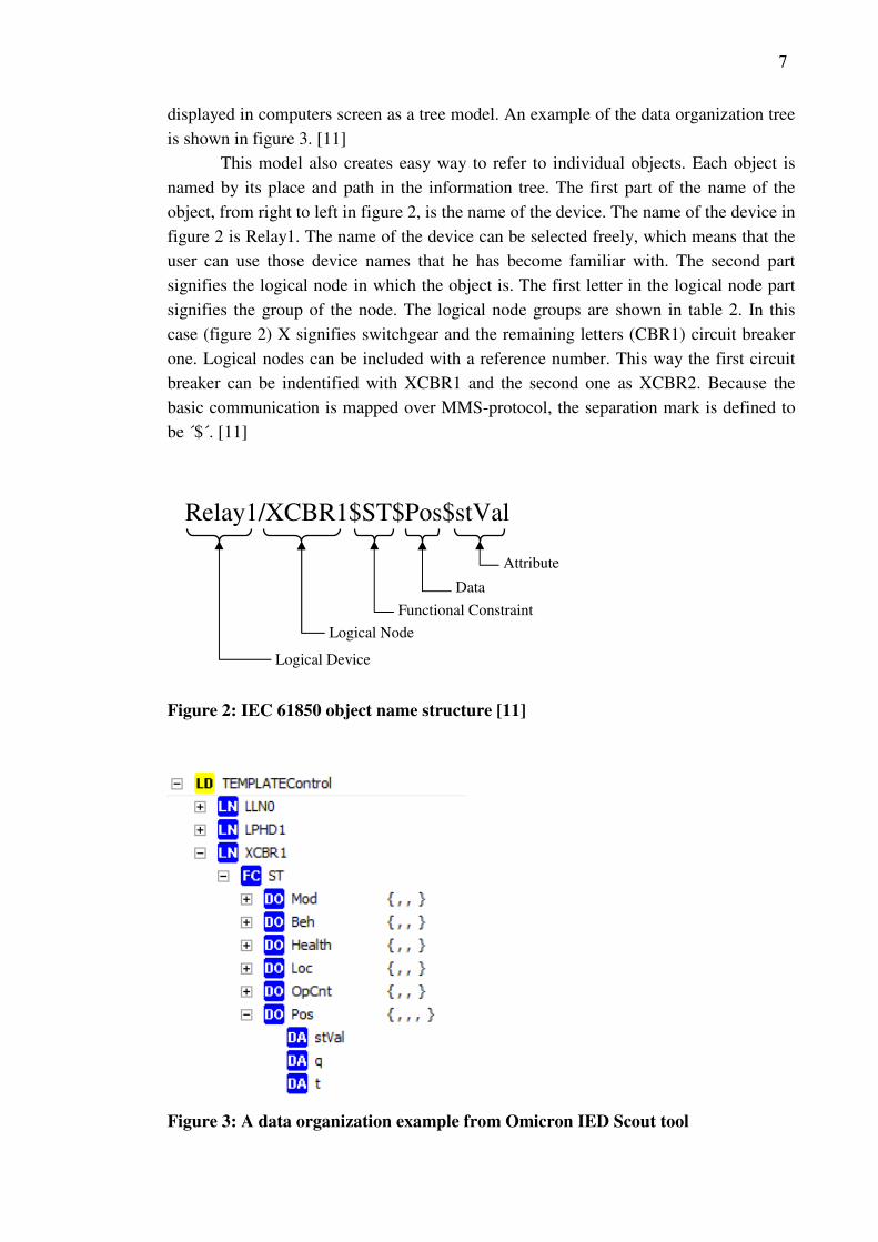
This model also creates easy way to refer to individual objects. Each object is
named by its place and path in the information tree. The first part of the name of the
object, from right to left in figure 2, is the name of the device. The name of the device in
figure 2 is Relay1. The name of the device can be selected freely, which means that the
user can use those device names that he has become familiar with. The second part
signifies the logical node in which the object is. The first letter in the logical node part
signifies the group of the node. The logical node groups are shown in table 2. In this
case (figure 2) X signifies switchgear and the remaining letters (CBR1) circuit breaker
one. Logical nodes can be included with a reference number. This way the first circuit
breaker can be indentified with XCBR1 and the second one as XCBR2. Because the
basic communication is mapped over MMS-protocol, the separation mark is defined to
be ´$´. [11]
Figure 2: IEC 61850 object name structure [11]
Figure 3: A data organization example from Omicron IED Scout tool
Relay1/XCBR1$ST$Pos$stVal
Logical Device
Logical Node
Functional Constraint
Data
Attribute

8
Functional constrain is there to group individual attributes. It specifies which
services can be used to access the following data. Individual attributes have predefined
functions and therefore they are grouped be their functionality. In IEC 61850 software it
is common that the functional constrain is used also to organize the information. In
figure 2 the functional constraint (ST) stands for status attributes. There are functional
constraints for description attributes (DC), substituted value attributes (SV), measurands
(MX), extended definition attributes (EX) and several other, which are listed in the
61850-7-2 part. The data part gives understandable name to the data. Data elements are
named by their functionality in the systems. In figure 3 Pos determines the position of
the circuit breaker and the attribute stVal contains the value of the status. [10, 9]
Logical node Groups Group
Designator
System Logical Nodes L
Protection functions P
Protection related functions R
Supervisory control C
Generic references G
Interfacing and Archiving I
Automatic control A
Metering and Measurement M
Switchgear X
Instrument Transformer T
Power Transformer Y
Further power system equipment Z
Sensors S
Table 2: Logical node Groupings [10]

9
2.5. Logical node concept
Logical devices are defined by logical nodes. The logical nodes describe the functions
and functional interfaces. A function may be constructed from multiple logical nodes
and the logical nodes can be located in different physical devices. Then the function is
called distributed. The logical nodes are linked by logical connections, which are
independent of the physical connections with the use of Ethernet solutions. The standard
pre-defines 92 logical nodes, but the logical node group is extensible which means that
manufactures are not bound to already existing nodes. The standard defines rules for
creating new logical nodes and common data classes. The rules for creating new objects
have been defined to preserve interoperability. [9, 1]
The logical node concept is in major role in the whole standard. The logical
nodes are the basic objects that exchange information and the “backbone” in modelling
real devices. The logical nodes contain some mandatory predefined sets of data objects
with specific data attributes. All these concepts have a logical structures and strong
semantics related to real substation automation devices and tasks. The information
contained in logical nodes is exchanged by services with well-defined rules and
performance requirements. [10]
Free allocation of functions means that any function may take place in any
device that supports IEC 61850 standard. This is achieved with definition of LN
(Logical Nodes) and PICOM (Piece of Information for COMmunication). PICOM is
used for transferring information between two logical nodes. It describes the logical
connection between two logical nodes and it contains also the information to be
transmitted, attributes for message performance requirement and possibly other
requirements. PICOM can not be used in multicast or broadcast procedures, because it
uses addresses for point-to-point communication. [12]
The definition of the PICOM concept is illustrated in figure 4. The control and
report services are a part of the interface of a logical node, which are mostly used in
normal operation. Substitution service enables to replace a data value with fixed one.
Get and set service is for reading and writing data set values. Dir and definition is for
reading the data directory information. [10]
Figure 4: PICOM concept [10]

10
Functions are tasks that are performed by substation automation. Functions are
built from logical nodes, which change data with each other. IEC 61850 defines that
only logical nodes are used to exchange data, and all functions must have one or several
logical nodes. The GSE (Generic Substation event) and the sampled value service
communication do not use PICOM’s. GSE (GOOSE and GSSE) messages are sent to
many IED’s simultaneously in the internal network (peer-to-peer communication). GSE
messages are specially used for fast operation when substation event occurs and
therefore GSE message can not contain as much information as defined in PICOM
concept. [12, 10]
2.6. IEC 61850 communication protocols
The IEC 61850 uses a protocol stack based on MMS, TCP/IP and Sampled Value
transfer. Manufacturing Message Specification (MMS) is an international standard
(ISO9506) and it was chosen because it supports the standards complex naming system
and services. With MMS the mapping is easier to understand since the objects are
named by their functionality, not by index and register numbers. MMS is specially
chosen because of its Virtual Manufacturing Device (VMD) model. MMS also allows
IED’s to provide client and server functions at the same time. [13]
The specification in MMS defines the rules for communication, which are:
message sequencing over the network, message formatting and encoding and MMS
layer interaction between other layers of the OSI-model. Simply MMS defines
communication messages sent between IED’s with the VMD-model. The VMD-model
defines the objects that are contained in a server, the services that the client can use to
access and manipulate the objects and the behaviour of the server when a client sends
service requests. [13]
Open System Interconnection Reference Model (OSI-model) is an abstract
description of designing network protocols. Basically OSI-model divides the network
architecture into seven layers: Application (layer 7), Presentation (layer 6), Session
(layer 5), Transport (layer 4), Network (layer 3), Data-link (layer 2) and Physical layer
(layer 1). The first three layers are referred as application function and the last four as
connectivity function. [6] In the OSI-model the MMS belongs to the application
functions (layers 5-7). Sampled values and GOOSE messages have not been mapped
into MMS, but straight into Ethernet layer, because they are considered as time critical
messages and can not contain lots of binary data. The GOOSE and Sampled values will
be covered mo detailed in chapter 2.12. Layers three and four consists of TCP/IP
protocols and layers one and two consists of Ethernet protocol. [14] The IEC 61850
protocol stack is shown in figure 5.

11
Figure 5: IEC 61850 protocol stack [14]
2.7. Physical communication
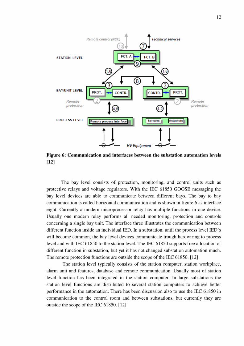
All functions in substation automation can be divided into three levels: process, bay,
and station level functions. The figure 6 illustrates the typical physical allocation of
substation automation devices. The process level contains devices such as: circuit
breakers, current transformers, etc. These devices are generally hardwired to bay level
and the transferred data basically consists of binary and analogue input or output
information such as voltage and current transformer outputs and trip controls from the
protective relay. The interface between the process level and the bay level is indicated
in figure 6 with numbers four and five. At the process level may also be IED’s, such as
intelligent sensors and actuators. Process level IED’s are connected to process bus
usually based on LAN technology. The future visions are that the all process level
devices would be connected to the process bus, so that no hardwiring will be needed.
[12]
12
Figure 6: Communication and interfaces between the substation automation levels
[12]
The bay level consists of protection, monitoring, and control units such as
protective relays and voltage regulators. With the IEC 61850 GOOSE messaging the
bay level devices are able to communicate between different bays. The bay to bay
communication is called horizontal communication and is shown in figure 6 as interface
eight. Currently a modern microprocessor relay has multiple functions in one device.
Usually one modern relay performs all needed monitoring, protection and controls
concerning a single bay unit. The interface three illustrates the communication between
different function inside an individual IED. In a substation, until the process level IED’s
will become common, the bay level devices communicate trough hardwiring to process
level and with IEC 61850 to the station level. The IEC 61850 supports free allocation of
different function in substation, but yet it has not changed substation automation much.
The remote protection functions are outside the scope of the IEC 61850. [12]
The station level typically consists of the station computer, station workplace,
alarm unit and features, database and remote communication. Usually most of station
level function has been integrated in the station computer. In large substations the
station level functions are distributed to several station computers to achieve better
performance in the automation. There has been discussion also to use the IEC 61850 in
communication to the control room and between substations, but currently they are
outside the scope of the IEC 61850. [12]
13
There are three basic topologies for physical communication implementation:
bus topology, ring topology, and star topology. [12] Each topologies has its advantages
and disadvantages, but by modifying and mixing these topologies, it possible to find the
best solution for every substation type. [15] More about bus topologies in chapter 2.8.
The physical communication can be accomplished by different methods. The standard
does not require a specific physical interface. For example wireless solutions are
possible.
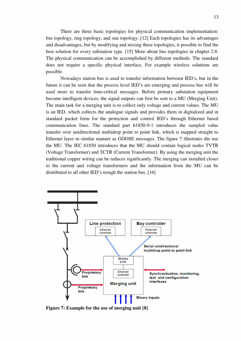
Nowadays station bus is used to transfer information between IED’s, but in the
future it can be seen that the process level IED’s are emerging and process bus will be
used more to transfer time-critical messages. Before primary substation equipment
become intelligent devices, the signal outputs can first be sent to a MU (Merging Unit).
The main task for a merging unit is to collect only voltage and current values. The MU
is an IED, which collects the analogue signals and provides them in digitalized and in
standard packet form for the protection and control IED’s through Ethernet based
communication lines. The standard part 61850-9-1 introduces the sampled value
transfer over unidirectional multidrop point to point link, which is mapped straight to
Ethernet layer in similar manner as GOOSE messages. The figure 7 illustrates the use
the MU. The IEC 61850 introduces that the MU should contain logical nodes TVTR
(Voltage Transformer) and TCTR (Current Transformer). By using the merging unit the
traditional copper wiring can be reduces significantly. The merging can installed closer
to the current and voltage transformers and the information from the MU can be
distributed to all other IED’s trough the station bus. [16]
Figure 7: Example for the use of merging unit [8]
14
2.8. ACSI (Abstract Communication Service Interface)
The IEC 61850 defines the ACSI, because the MMS, GOOSE or Sampled Values do
not themselves include naming conventions that support electric substation
communication. The ACSI can be also mapped to other protocols, thus the standard
needs only a partly update to map the ACSI over state-of-the-art technology.
The ASCI provides a virtual image of the substation. The virtual image is
generated with the use of the classification approach. The virtual system does not only
provide a virtual image, but it also provides real data real-time from the physical
devices. The whole system with all of its information can no be seen from every single
computer, but visibility of individual attributes can be modified. The diverse access
schemes can be used to provide or restrict the particular devices visibility. Basic
information about the IEC 61850 substation network security is discussed in chapter
2.17. [10]
The adoption of abstraction technique is one of the most significant features in
the IEC 61850 standard. The abstraction involves that objects are independent of
underlying protocols, which means that abstraction technique isolates the information
models and services from the on-the-wire protocol. Compared to earlier protocols used
in substation automation the abstraction has powerful benefits. The abstract definition
means that the description focuses on aspects on what the services are indented for
instead of describing how the services are build. [17]
The abstract definition in IEC 61850 services means that only aspects that are
visible and accessible over network are modelled. This is the reason for hierarchical
class model. The abstraction in ACSI has a second meaning, which is that the device
cooperation is only conceptual and the concrete solution are defined in the SCSM’s
(Specific Communication Service Mapping). Therefore the ACSI is independent of the
underlying communication system. This way the standard can easily be adapted to the
state-of-the-art communication technology in the future. [18]
The ACSI describes communication between server and client. It provides
interfaces for: real-time data access and retrieval, device control, event reporting and
logging, publisher/subscriber, self-description of devices, data typing and discovery of
data types, and for file transfer. The ACSI provides interfaces also for substation event
distribution (GOOSE and GSE) and for transmission of sampled values. [18]
The figure 8 shows a concept model for reporting and logging. The data, that is
wanted to reported, is grouped in to data sets. The data sets should be well chosen to fit
to specific needs. The reporting needs also triggering option (TrgOps), which define the
situation when the corresponding data set is reported or logged. The triggering option
dchg is set to true or enabled, each time a single data attribute changes it value, the full
data set is transmitted from the IED. The qchg option means that the data set is
transmitted when a quality of an attribute changes. The standard defines that the
messages can be sent as buffered or unbuffered. The buffer means that the message stay
in the memory until it is ensured that the message is received by the client. Usually the

15
buffered messaging is the preferred method, because it prevents message losses. Data
sets are used also to set up GOOSE messages, but since the GOOSE message itself and
GOOSE services are limited, the subscriber has to be configured to receive the
messages. [10]
Figure 8: Reporting and logging concept schema [10]
2.9. MMS (Manufacturing messaging specification)
Currently the IEC 61850 abstract services (ACSI) defined in 61850-7-2, 61850-7-3 and
61850-7-4 are mapped over MMS, apart from GOOSE and sampled value transfer. The
part 61850-8-1 defines how the ACSI services, concepts and objects are mapped to
MMS services. An instance of ACSI server class is mapped to MMS virtual
manufacturing device (VMD) object, which is the part that enables the monitoring and
control services. The table 3 show services which has been mapped to represent IEC
61850 ACSI objects. [6]

16
MMS Object IEC 61850
Object
MMS Service in use
Application Process
VMD
Server Initiate, Conclude, Abort, Reject, Cancel,
Identify
Named Variable
Objects
Logical Nodes
and Data
Read, Write, InformationReport,
GetVariableAccessAttribute
Named Variable List
Objects
Data Sets GetNamedVariableListAttributes,
GetNameList, DefineNamedVariableList,
DeleteNamedVariableList, Read, Write,
InformationReport
Journal Objects Logs ReadJournal, InitializeJournal,
GetNameList
Domain Objects Logical Devices GetNameList, GetDomainAttributes,
StoreDomainContents
Files Files FileOpen, FileRead, ObtainFile,
FileClose, FileDirectory, FileDelete
Table 3: The MMS service mapping within the SCSM of IEC 61850-8-1 [6]
The MMS uses the seven layer OSI-model, which has been introduces already in
chapter 2.6. The MMS takes the layers 7-5 and the TCP/IP layers 4 and 3, which is
shown in figure 9. The communication is based on client/server relations and devices
are identified by the devices IP addresses. As discussed earlier the physical device acts
as a proxy server to all logical devices in the same IED and with use of Ethernet the
devices can physically locate anywhere in the network. [6]
The logical devices are mapped to MMS Domain objects and for each logical
device there shall be one MMS domain. The logical nodes are mapped to MMS
NamedVariable objects and other ACSI objects are mapped similarly. This way the
MMS object-oriented modelling support the ACSI and naming conventions based on
substation automation. The MMS is fairly complicated protocol, so detailed description
of the MMS is outside the scope of this paper. [7, 19]

17
Figure 9: IEC 61850 service message types. [6]
2.10. GSSE, GOOSE and Sampled Values
There are two different GSE (Generic Substation Event) communication systems in IEC
61850. GSSE (Generic Substation Event) is an extended version from the earlier UCA.2
version for transmitting substation events. GOOSE is newer and more flexible system
for transmitting data-sets and therefore the GOOSE has become more used in new
applications. The difference between GOOSE and GSSE is that GOOSE supports
analog, binary and integer value data types and GSSE supports only fixed binary event
status type. Both GOOSE and GSSE use multicast services to send substation event
messages. [20] The most important aspect about that GOOSE is can be used for
horizontal communication between bay level IED’s. The GOOSE is feature is a major
benefit compared to earlier substation automation standards, because the GOOSE is
ideal for fast messages transmitted trough the network. With the GOOSE for example
the interlocking, auto-reclosing, inter-tripping, and trip signals are faster to implement.
[22]
GOOSE is mapped straight to Ethernet layer to provide fast real-time operation
and it is used to implement traditional protection schemas such as interlocking, tripping
circuit breakers and status indications. All these services are high priority services for
example a circuit breaker trip command must be delivered within 4 milliseconds and
with GOOSE it is possible to deliver such messages even faster. The GOOSE is a

18
flexible tool, because it can serve different applications that have different types of
performance requirements and it can use various data types. [20]
SV (Sampled Value) messages are used to transfer digitalized measured values.
The measured values are sampled from a continual stream of analogue metering with a
predefined rate. This task can be done for example by an intelligent instrument or by a
merging unit. The frequency of the sampling rate can be freely selected to be suitable
for the individual target. For protection purposes sometimes the sampling rate and value
limits has set so that nuisance alerts can be reduced. As seen in figure 5 the
transmission of SV has also been mapped directly to the Ethernet layer.
GSE and SV messages are both mapped directly to the Ethernet layer, because
they are designed to provide fast communication. This solution ensures that the
transferred communication packets have minimum amount of information. Both
messaging systems have also strict performance requirement, which is explained in
chapter 2.13.
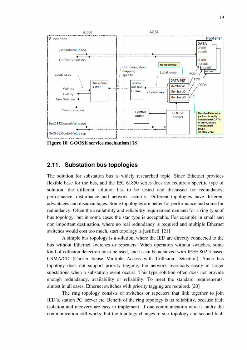
For a substation automation engineer working with IEC 61850 it is important to
understand the mechanisms in GOOSE service, because it is one main feature of IEC
61850 compatible relays. When a substation event occurs and one or several data-
attributes change their state, the publisher transmission buffer is updated. The local
service “publish.reg” transmits the changes values to the publisher transmission buffer
combined with a GOOSE message. Next the specific mapping services will update the
subscriber buffer automatically. The subscriber receives the new values and may
forward the message appropriately. The mechanism of the GOOSE service is shown in
figure 10 below. [21]
GOOSE service has to follow a retransmission scheme, which ensures that
messages are received when using multicast transmission. Because the GOOSE is
mapped directly to the Ethernet layer, it does not have built in services to insure
message delivery, such as in TCP/IP communication. Retransmission scheme is
explained in chapter 2.15. [21]
19
Figure 10: GOOSE service mechanism [18]
2.11. Substation bus topologies
The solution for substation bus is widely researched topic. Since Ethernet provides
flexible base for the bus, and the IEC 61850 series does not require a specific type of
solution, the different solution has to be tested and discussed for redundancy,
performance, disturbance and network security. Different topologies have different
advantages and disadvantages. Some topologies are better for performance and some for
redundancy. Often the availability and reliability requirement demand for a ring type of
bus topology, but in some cases the star type is acceptable. For example in small and
non important destination, where no real redundancy is required and multiple Ethernet
switches would cost too much, start topology is justified. [21]
A simple bus topology is a solution, where the IED are directly connected to the
bus without Ethernet switches or repeaters. When operation without switches, some
kind of collision detection must be used, and it can be achieved with IEEE 802.3 based
CSMA/CD (Carrier Sense Multiple Access with Collision Detection). Since bus
topology does not support priority tagging, the network overloads easily in larger
substations when a substation event occurs. This type solution often does not provide
enough redundancy, availability or reliability. To meet the standard requirements,
almost in all cases, Ethernet switches with priority tagging are required. [20]
The ring topology consists of switches or repeaters that link together to join
IED’s, station PC, server etc. Benefit of the ring topology is its reliability, because fault
isolation and recovery are easy to implement. If one communication wire is faulty the
communication still works, but the topology changes to star topology and second fault

20
in the communication is fatal. Ring topology support long communication wires, since
the messages are repeated at every switch or repeater. Usually IED’s that support ring
topology are equipped with repeaters. Without priority tagging and Ethernet switches
the transmission of important messages may be delayed, because the switches route all
communication to the same wires that connects the ring. A simple example of ring type
communication architecture is shown in figure 11. [20]
In star topology the station computer, server etc. are connected to Ethernet
switch, which connect to switches below, towards the process bus. Since IED’s are
connected via one or more switches to the station computer, and if one switch in the
path to the station computer fails, messages can not be delivered. With star topology the
network does often meet performance requirements, but compared to ring topologies it
has poor reliability. [20]
Figure 11: Simple examples of star (left) ring (right) type communication
architectures [22]
Usually mixed approaches are used in substation projects to meet the standards
requirement, to lower communication system costs etc. In cascaded star topology a set
of IED’s are connected to one switch and several switches are connected together to
form a cascade structure. The station computer etc. devices are connected to one of the
cascaded switch. The amount of parallel switches is limited by delay in every switch
and this type topology does not provide good reliability if one switch fails. Reliability
can be achieved by connecting the cascaded switches by the end switches in a loop via
one extra switch connected to the station level devices. This type of solution is called a
star-ring topology. By creating a ring structure, it is possible that the messages would
circulate in the loop forever, since normal Ethernet switches do not support loop
structures. Therefore managed switches should be used. Managed switch uses an RSTP

21
(Rapid Spanning Tree Protocol) which is defined in standard IEEE 802.1w. Compared
to other topologies the star-ring topology is more expensive and complex, but it often
offers the needed performance and reliability. [15, 20]
2.12. Time Synchronization
Because the substation events have strict performance requirements the time
synchronization has important role in IEC 61850. For the purpose of organisation of
substation events, the time tags of the events must be coherent. With the IEC 61850 a
vast amount of information is available in a fast rate and in order to organize for
example events from several IED’s in a database, the time source must be able to
provide coherent time to all the IED’s. When a substation event occurs the event
information has to be organized in the storages in the same order as they are published.
This way the right sequence of event can be restored and right decisions and calculation
can be made. [23]
The standard defines five different classes for time synchronization. First two T1
and T2 is defined for normal event tagging, which are shown in table 4, and rest T3, T4,
and T5 are for instrument transformers, which are shown in table 5. The P1, P2, P3 in
table 5 means that the raw data is used for protection and control purposes and M1, M2
and M3 are for metering purposes. The sampling rates for metering are high due to
monitoring for harmonics. [12]
Time performance
class
Accuracy
(ms)
Purpose
T1 ±1 Event time tagging
T2 ±0,1 Time tags to support point on wave
switching
Table 4: Time synchronization accuracy requirements for control and protection
events [12]
Time performance class Accuracy (µs) Reference rate (Samples/s)
T3 ±25 P1 480
P2 960 T4 ±4
M1 1500
P3 1920
M2 4000
T5 ±1
M3 12000
Table 5: Time synchronization accuracy requirements for instrument
transformers [12]

22
The IEC 61850 states that the time synchronization method using LAN should
be SNTP and other method are outside the scope of the standard. The common methods
to synchronize distributed clocks in LAN’s are NTP (Network Time Protocol) and
SNTP (Simple Network Time Protocol), which can achieve accuracies in the range of
millisecond. Radio signals and GPS (Global Position System) can be used also to
implement time synchronization. It is theoretically possible to achieve high precision
synchronization with the GPS, but such system would be very expensive compared to
LAN solutions. [23]
The problem with conventional solution with SNTP is that it is only able to
provide accuracy about 1 millisecond, which is not enough for raw data sample values
and for merging units. One solution is to use IRIG-B. The IRIG-B means the standard
Inter-Range Instrumentation Group time code B. The IRIG-B is not a time source itself,
but it need an external time source for example a GSP clock, and thus it needs extra
wiring. Since the automation does not work properly without time synchronization, the
system has to be redundant. In the case of IRIG-B the external time sources have to be
doubled or an alternative time source could be a SNTP master. [24, 15]
The PTP (Precision Time Control) described in IEEE 1588 standard has been
developed to meet these requirements. With PTP it is possible achieve less than one
microsecond accuracy with the distributed clocks through Ethernet. The PTP has been
developed with aims for accuracy in the microsecond range, minimum requirements for
system performance, low administration efforts, use via Ethernet with multicast
capability and specification as an international standard. PTP is becoming popular
solution not only in substation automation, but in all automation which needs time
synchronization. [23]
2.13. Communication performance requirements
Different message types have different performance requirements. The performance
requirements are defined as requirements for allowed message transfer time. The
transfer requirements are supported by time tags and time synchronization. The
performance requirements are independent of the substation size, because the
requirements are defined per message. [11] The IEC 61850 has specified few types of
performance requirements shown in table 6. Figure 5 shows the types which message
types and performance requirements each application uses. [20]
The 1A type message has the most strict requirements and it is used for trip
indication, interlocking and for protection logic. The 1B type is for messages which
have less strict performance requirements. The type 2 is time-tagged, but the message
content has less performance requirements than the type 1 messages. The type 2
message may alternatively include one measurement value. The type 3 is used for
complex messages which may be equipped with a time-tag. The type 3 requirement is
used for example in messages such as normal event handling messages or in non-
electrical related Measurands. The type 4 is intended to be used for raw data transfer

23
from digital instrument transformers and transducers. Type 5 is used for file transfer and
type 6 is defined for synchronization purposes. Because the time synchronization used
for variety of services and applications, different classes are required. The time
synchronization is discussed in more detail in chapter 2.12. [12]
Type Application Performance
Class
Requirements
(Transmission
Time)
P1 10 ms 1A
Fast Messages
(Trip) P2/P3 3 ms
P1 100 ms 1B
Fast Messages
(Other) P2/P3 20 ms
2 Medium Speed 100 ms
3 Low Speed 500 ms
P1 10 ms 4 Raw Data
P2/P3 3 ms
5 File Transfer ≥1000 ms
6 Time
Synchronization (Accuracy)
Table 6: Message type performance requirements [20]
IEC 61850 defines three different event types that need dedicated time
allocation. In first scenario time tag is needed when an event is created by IED’s
internal calculation. In second scenario a change of a binary input creates an event that
needs time tagging. And in third scenario an event is created by a change in an analogue
input. In the second and third scenario the delays must be considered and the times shall
be locally corrected. The time correction should be accurate as possible and the
correction should be added to the message before transferring, not at the receiving end.
The whole transfer time consists of the communication processing times at both ends
and the time that it takes to transfer the message from source to sink. The time between
IED’s includes the time on the wire and times consumed in routers and other devices.
Because the performance requirements are independent of the systems physical network
implementation, the individual systems performances must always be tested, before it
can be stated that the system meets the requirements. [12]
24
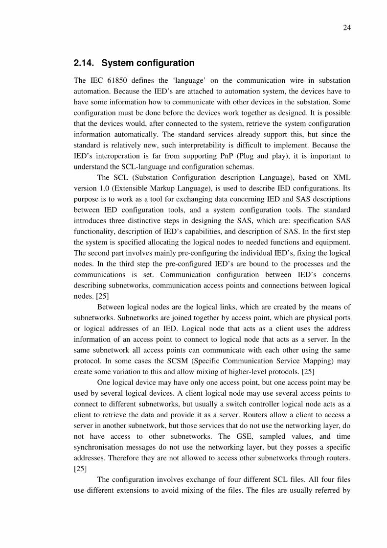
2.14. System configuration
The IEC 61850 defines the ‘language’ on the communication wire in substation
automation. Because the IED’s are attached to automation system, the devices have to
have some information how to communicate with other devices in the substation. Some
configuration must be done before the devices work together as designed. It is possible
that the devices would, after connected to the system, retrieve the system configuration
information automatically. The standard services already support this, but since the
standard is relatively new, such interpretability is difficult to implement. Because the
IED’s interoperation is far from supporting PnP (Plug and play), it is important to
understand the SCL-language and configuration schemas.
The SCL (Substation Configuration description Language), based on XML
version 1.0 (Extensible Markup Language), is used to describe IED configurations. Its
purpose is to work as a tool for exchanging data concerning IED and SAS descriptions
between IED configuration tools, and a system configuration tools. The standard
introduces three distinctive steps in designing the SAS, which are: specification SAS
functionality, description of IED’s capabilities, and description of SAS. In the first step
the system is specified allocating the logical nodes to needed functions and equipment.
The second part involves mainly pre-configuring the individual IED’s, fixing the logical
nodes. In the third step the pre-configured IED’s are bound to the processes and the
communications is set. Communication configuration between IED’s concerns
describing subnetworks, communication access points and connections between logical
nodes. [25]
Between logical nodes are the logical links, which are created by the means of
subnetworks. Subnetworks are joined together by access point, which are physical ports
or logical addresses of an IED. Logical node that acts as a client uses the address
information of an access point to connect to logical node that acts as a server. In the
same subnetwork all access points can communicate with each other using the same
protocol. In some cases the SCSM (Specific Communication Service Mapping) may
create some variation to this and allow mixing of higher-level protocols. [25]
One logical device may have only one access point, but one access point may be
used by several logical devices. A client logical node may use several access points to
connect to different subnetworks, but usually a switch controller logical node acts as a
client to retrieve the data and provide it as a server. Routers allow a client to access a
server in another subnetwork, but those services that do not use the networking layer, do
not have access to other subnetworks. The GSE, sampled values, and time
synchronisation messages do not use the networking layer, but they posses a specific
addresses. Therefore they are not allowed to access other subnetworks through routers.
[25]
The configuration involves exchange of four different SCL files. All four files
use different extensions to avoid mixing of the files. The files are usually referred by
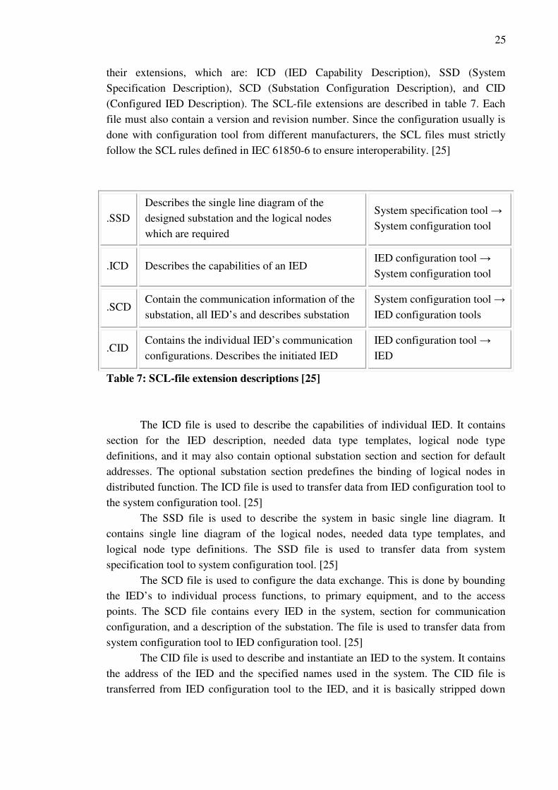
25
their extensions, which are: ICD (IED Capability Description), SSD (System
Specification Description), SCD (Substation Configuration Description), and CID
(Configured IED Description). The SCL-file extensions are described in table 7. Each
file must also contain a version and revision number. Since the configuration usually is
done with configuration tool from different manufacturers, the SCL files must strictly
follow the SCL rules defined in IEC 61850-6 to ensure interoperability. [25]
.SSD
Describes the single line diagram of the
designed substation and the logical nodes
which are required
System specification tool →
System configuration tool
.ICD Describes the capabilities of an IED IED configuration tool →
System configuration tool
.SCD Contain the communication information of the
substation, all IED’s and describes substation
System configuration tool →
IED configuration tools
.CID Contains the individual IED’s communication
configurations. Describes the initiated IED
IED configuration tool →
IED
Table 7: SCL-file extension descriptions [25]
The ICD file is used to describe the capabilities of individual IED. It contains
section for the IED description, needed data type templates, logical node type
definitions, and it may also contain optional substation section and section for default
addresses. The optional substation section predefines the binding of logical nodes in
distributed function. The ICD file is used to transfer data from IED configuration tool to
the system configuration tool. [25]
The SSD file is used to describe the system in basic single line diagram. It
contains single line diagram of the logical nodes, needed data type templates, and
logical node type definitions. The SSD file is used to transfer data from system
specification tool to system configuration tool. [25]
The SCD file is used to configure the data exchange. This is done by bounding
the IED’s to individual process functions, to primary equipment, and to the access
points. The SCD file contains every IED in the system, section for communication
configuration, and a description of the substation. The file is used to transfer data from
system configuration tool to IED configuration tool. [25]
The CID file is used to describe and instantiate an IED to the system. It contains
the address of the IED and the specified names used in the system. The CID file is
transferred from IED configuration tool to the IED, and it is basically stripped down

26
version of the SCD file. The SCD file contains all information concerning system
configuration and a CID contain only data concerning the IED. [25]
The standard defines that IED, which has been configured to work also as a
server, must be able to produce ICD file or accompanied with one. It must also be able
to consume an SCD file. It is not mandatory that IED’s can perform these tasks
independently, but the tasks can as well be performed with the help of engineering tools.
The SCL allows manufacturers to create small private parts, for the devices and tools
internal use, into the SCL files, which can only be interpret or possibly modified with
the manufacturers tool. All other tools can only regard them, but private part should not
be deleted, but kept along for future use. The private parts should not be used to
describe information which is required for full interoperation. [25]
The figure 12 illustrates the exchange of SCL-files between the different
configuration tools. At first the ICD-files are retrieved from the IED configuration tool
or directly from the IED’s. The system is first designed with the system specification
tool and the SSD-file and the ICD-files are transferred to the system configuration tool.
The ICD-files and the SCD-file is used to with the station computer configuration and
finally the configured CID-files are used to configure the IED’s. Different
manufacturers have slightly different approaches to the configuration tool. Four
different configuration tools for substation automation configuration could be
considered to be too many and a common solution is to integrate some of the tools. For
example the system specification tool, system configuration tool and station controller
configuration tool are sometimes integrated to one tool. The configuration of an
substation automation system starts from defining the substation in a single line diagram
and ends to the individual IED configuration.

27
Figure 12: An example substation configuration schema with SCL files [26]
2.15. Retransmission scheme
Because GOOSE is mapped straight to the Ethernet layer and it does not use the
addressing layer, it does not use device addresses but a network address and therefore
messages are sent as a multicast. In multicast communication model a protective relay
detects a fault and sends a GOOSE message as a multicast to the network. Other relays
inside the network receive the GOOSE and duplicate it to the same network. This
creates architectural challenges when transferring messages between substations. This
means that the system must be able to handle message loss, duplicated messages,
delayed messages and loss of connection. [20] The retransmission schema, shown in
figure 13, ensures that message is received by the subscriber. GOOSE messages are sent
constantly to the network. If an substation event occurs and the status of a data point
changes, the GOOSE messages are sent more rapidly.
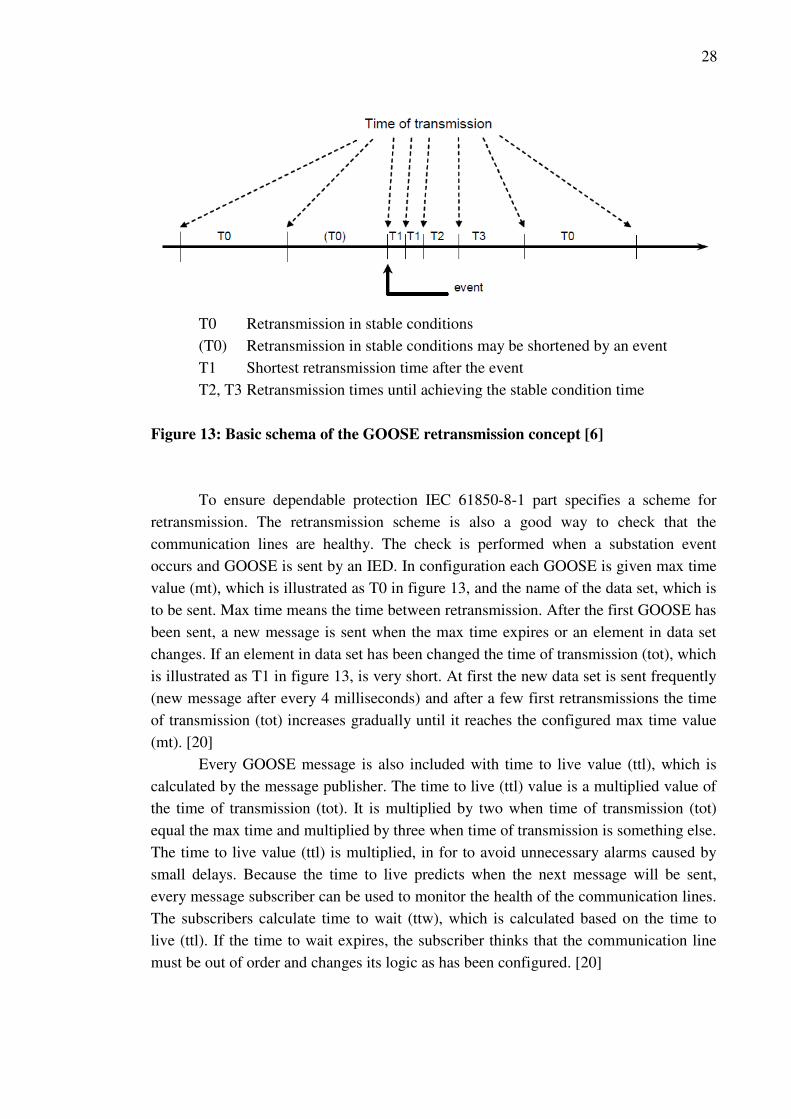
28
T0 Retransmission in stable conditions
(T0) Retransmission in stable conditions may be shortened by an event
T1 Shortest retransmission time after the event
T2, T3 Retransmission times until achieving the stable condition time
Figure 13: Basic schema of the GOOSE retransmission concept [6]
To ensure dependable protection IEC 61850-8-1 part specifies a scheme for
retransmission. The retransmission scheme is also a good way to check that the
communication lines are healthy. The check is performed when a substation event
occurs and GOOSE is sent by an IED. In configuration each GOOSE is given max time
value (mt), which is illustrated as T0 in figure 13, and the name of the data set, which is
to be sent. Max time means the time between retransmission. After the first GOOSE has
been sent, a new message is sent when the max time expires or an element in data set
changes. If an element in data set has been changed the time of transmission (tot), which
is illustrated as T1 in figure 13, is very short. At first the new data set is sent frequently
(new message after every 4 milliseconds) and after a few first retransmissions the time
of transmission (tot) increases gradually until it reaches the configured max time value
(mt). [20]
Every GOOSE message is also included with time to live value (ttl), which is
calculated by the message publisher. The time to live (ttl) value is a multiplied value of
the time of transmission (tot). It is multiplied by two when time of transmission (tot)
equal the max time and multiplied by three when time of transmission is something else.
The time to live value (ttl) is multiplied, in for to avoid unnecessary alarms caused by
small delays. Because the time to live predicts when the next message will be sent,
every message subscriber can be used to monitor the health of the communication lines.
The subscribers calculate time to wait (ttw), which is calculated based on the time to
live (ttl). If the time to wait expires, the subscriber thinks that the communication line
must be out of order and changes its logic as has been configured. [20]

29
2.16. System reliability and redundancy
When talking about substation automation, redundancy is an obvious concern. It is vital
for substation automation that the systems are endlessly reliable. Since microprocessor
technology added with state-of-the-art communication technology creates complexity to
the hardware and software, the redundancy should be ensured in every level and in
multiple ways. Large high voltage substations have commonly two parallel protection
systems and other solution that create redundancy and reliability. In lower voltage
where parallel systems are not used, the IEC 61850 offers other means towards more
reliable systems. This is done by modelling redundancy in different levels of the system:
IED internal, communication system level, and application level. Usually redundancy
has been mainly issue of the amount of components and parallel systems in the
substation.
Internal IED redundancy depends only from the manufacturers and it is outside
the scope of the standard. Basic solution to improve redundancy in communication level
is to select a switch based ring structure for the station bus. This solution offers
reliability if one switch fails. In application level the IEC 61850 has a lot to offer, since
redundancy can modelled straight to the functions. Application level redundancy is
modelled in SCL, by naming each IED individually, providing additional subnetworks,
and linking logical nodes. [25]
IEC 61850 series defines that a substation shall be able to operate even if one
component in the substation automation system fails. This requirement is referred as
‘graceful degradation’ in the standard. Redundancy is only one way to add reliability,
but should also be added with great care. [27] With IEC 61850 the reliability of the
system often depends on the reliability of the network solutions. This generates a lot of
requirements for the Ethernet switches and for the used network structure.
Modern Ethernet switches are IED’s themselves, which can be configured. An
Ethernet switch has multiple ports that connect individual IED’s and forms a network of
IED’s. A switch uses MAC-addresses (Media Access Control) to transmit common
messages. It talks to all connected IED’s simultaneously. If a message is received, it
examines the MAC destination of the message and sends it to the one port that connects
to the destination IED. GOOSE-messages do not use destination addresses, so an
Ethernet switch sends a received GOOSE to all other ports apart the port from the
message input port. [20]
When a substation event occurs, messages are generated constantly. The
network traffic increases rapidly and the possibility of a message collision escalates.
Message collision generates delays and in the worst cases message failures. The
message delays are generated from the time that it takes a switch to process a message.
This is called latency delay. The delay may be longer if the message can not be sent,
because another is being sent, then the message waits in the memory for its turn to be
sent. [20]
30
As mentioned before in communication performance requirements chapter 2.13,
different message types have different performance requirements. And since GOOSE
message have strict performance requirements, the transmission of GOOSE messages
has to be ensured. One solution for this is to use VLAN (Virtual Local-Area Network).
VLAN can be used to divide physically connected network to needed network segment,
which reduces overall network traffic. Second solution is to use priority tagging. Each
message has a tag that signifies the importance of the message, and in case of backlog,
the message with higher priority is sent first. When designing a system, it must be noted
that most modern microprocessor relays support eight different levels of priority tags,
but all switches do not. [20]
For a redundant communication network the LAN should be looped or there
should be multiple connections between access points. The RSTP (Rapid Spanning Tree
Protocol), used by an Ethernet switch, detects the fault connection wire and reconfigures
the topology. RSTP itself does not provide redundancy against a switch. In critical high
voltage substation the system costs are not an issue and full redundancy of the network
is justifiable. Then system can be provide with to identical and parallel networks, which
can also be connected to together by IED’s that have two Ethernet ports. New
generation relays have two Ethernet ports that work simultaneously, connected to two
different networks. [20]
The Ethernet switches are in major role in concerning the networks reliability.
With priority tagging the performance of the messages can be achieved and with loop
support the messages do not circulate in the network ring. Since the switches are locate
in the substation, they are affected by electromagnetic, electric and magnetic fields, the
casing of the switch must be done and tested properly and support for fibre optics
should be considered. Since performance and reliability are major issues the costs of the
switches should not be the first constrain. [20]
2.17. Security
This chapter provides just a thin picture about the security of the substation network
with IEC 61850. The standard does not contain security solutions in itself. The aspect of
cyber-security is outside the scope of the standard, and therefore it is mainly up to
manufacturer and distribution companies to consider their communication solution and
system protection.
Since IEC 61850 relies on state-of-the-art communication protocols, it confronts
such security issues as intrusion attacks. Ethernet provides some security on its own
against malicious intruders, but such technologies for cyber protection as IP-routing,
firewall, VPN (Virtual Private Network) and IDS (Intrusion Detection System) is
needed to ensure secure operation outside the substation. IEC 61850 provides itself
some security in form of access control, but to ensure private and secure system, more
security protection should be provided. [28]

31
Firewalls, IDS’s etc. focus on individual devices on a network and slow down
communication due to operation times. The problem is that the firewalls, intrusion
detection software has to be applied carefully, since the real-time operation
requirements are strict. This point orientated security is conventional and common.
Other point of view is to apply the security via software “agent” that plugs into existing
network in a transparent manner. The agent software would not be attached to a single
point, but would perform active security analysis. The protection could be implemented
through strategically placed routers. [29]
Other functions need demand more secure operation than others. It shall be
noticed that, encrypting messages leads to longer processing times and such high-
priority messages as interlocking messages between substations must be fast, but still
secured. Therefore using encryption must be evaluated carefully with the help of
experts. IEC working group 57 is working on this problem and IEC/TR 61850-90-1 is
expected to be published at 2010.
Usually distribution companies use their own communication solutions, which
are not directly accessible from outside the system. A fairly common solution is to have
electric cables, which have optic fibre in the same cable. This way the system can be
build so that the networks in the substations are not accessible from the outside network.
The only access point from the outside networks would be routed from the control
station, and thus the security could be implemented centralized.

32
3. IEC 61850 AND WIND POWER
3.1. Evaluation perspectives
This section of the thesis evaluates the IEC 61850 standards impacts and possibilities in
wind power system. The purpose of this section is not to give detailed description of the
IEC 61400-25, but to evaluate which kind of impacts does the IEC 61850 concepts have
to the wind power systems. The evaluation is focused in wind power markets and the
state of wind power systems in Finland. The evaluation is not inclusive, but a short
summary of the IEC 61850 benefits to wind power systems from a substation
automation system vendors perspective. Although the evaluation only considers
Finland’s situation, the evaluations apply to global situation in some extend.
Wind power is aggressively growing branch globally, which is consequence of
strong politic efforts to reduce carbon oxide emissions. In Finland on 6 November 2008
the Government approved a new Climate Change and Energy Strategy, which stated
that the goal to produce 6 TWh electricity with wind power annually. This amount of
annually produces energy corresponds to 2000 MW of installed wind power depending
on the placements of the wind power plants. A feed-in-tariff is introduced to enforce
these targets. [30, 31] These targets forecast a rabid development in wind power
segment, since at May 2009 Finland had only 144 MW of installed wind power attached
to the national power grid. [32]
3.2. IEC 61400-25 and IEC 61850
IEC 61850 has been extended to support monitoring, information exchange and control
of wind power plant. The extended version is called IEC 61400-25 and the focus of it is
in the communication between the actors such as SCADA systems and wind power
plant components. Information concerning substations and feeders the IEC 61400-25
relies on IEC 61850. [33] The application section of the IEC 61400-25 covers all
components which operate a working wind turbine, such as meteorological system,
electrical system and management system including mechanical systems in wind power
generation. The IEC 61400-25 is an obvious addition after the IEC 61850, because the
possibility for distributed protection, monitoring and controlling is beneficial in wind
power systems. IEC 61850 could be used as it is in wind power systems, but since the
IEC 61850 does not cover the additional equipment needed for monitoring and
controlling wind power plants, it can not be used to for all data generated from a wind
power plant. The IEC 61400-25 has been divided into six different parts, which are
shown in table 8. [34]

33
Parts Title Description
1 Overall description of principles
an models
Overview of models and crucial
requirements and basic principles
2 Information model The description of common process data,
meta-data and configuration data
3 Information exchange model Service models to get, set and subscribe to
wind power plant information
4 Mapping to communication
profiles
Mapping for web services, MMS and other
profiles
5 Conformance testing Specifies techniques of testing
implementations
6 LN classes and Data classes for
Condition Monitoring
Defines information models for additional
condition monitoring systems
Table 8: The six parts of the IEC 618400-25
The IEC 61400-25 only extends the IEC 61850 to fit for the communication in
wind power plants. Figure 13 shows an example of the allocation of functions and parts
of the two standards in a wind power application.
Figure 13: An example of modelling a wind power system with the IEC 61400-25
and IEC 61850 [34]
34
3.3. The impact of the new standards
The IEC 61400-25 has been designed to support the needs of wind mill maintenance.
The wind power plant owners want to increase the responsibility in the maintenance and
operation of the wind mills. Previously the manufacturers have provided maintenance
services for fault-correction and preventive maintenance, which causes relatively high
costs to the owners. The IEC 61400-25 supports more accurate information and more
sophisticated maintenance. [34] Secondly the new standards offer all the benefits of IEC
61850: interoperability, fast communication, easy access to relevant data due to the
clever semantics and benefits to system design etc. Wind power plants require seamless
supervisory and IEC 61850 and IEC 61400-25 offer just that.
The maintenance is in major role, because it creates lot of variable costs to the
owner. In wind power plant the variable costs are fairly stable apart from the
maintenance costs. With sophisticated maintenance supervision non-scheduled and
fault-correcting maintenance can be reduced. With flexible possibilities to implement
communications, it is possible that the wind mill manufacturers supervise the system for
maintenance purposes and the owners operate and supervise the mill at the same time.
[35]
Since IEC 61400 and IEC 61850 are relatively new addition to the IEC
standards, primary equipment measurement units with compatible communications are
still not generalized in markets. Some kind of transition devices would be needed,
before intelligent primary devices emerge to the markets. Similar devices as MU, which
offer information in digitalized form, would be TCD (Turbine Controller Device) and
CMD (Condition Monitoring Device) in wind power systems. The TCD would gather
measurements concerning the turbine and the CMD would gather information
concerning condition of the devices. All gathered information is then offered forward in
IEC 61850/61400-25 compatible form. The TCD and CMD may also exchange
information between each other. [35]
Wind power turbines are continuously growing in size. In today’s markets the
largest unit size about seven megawatts. Lager unit sizes demand more complex
solutions and therefore seamless communication is vital. Larger mills need fast and
reliable communication for example in the, most common type of wind turbine,
horizontal axis turbine the drive train faces great forces and is expensive to repair.
Because the properties of the wind can not be predicted with sufficient accuracy, the
individual wind mill unit needs fast automation, which enables more optimized
production. Because the IEC 61850 and IEC 61400-25 offer a single interface for wind
mill application, substation communication with all additional equipment the full
automation should be fairly simple to implement. [35]
Although projects done with the new standards are mainly only demonstrations,
the demonstrations have been mostly successful and show the potential of the new
standards. The new standards are useful especially in wind farms, since they offer
interoperability between different manufacturer’s devices and therefore the wind farms
35
owner can easily build new wind mill units among the old ones and change equipment
as they see fit. This increases the lifespan of older systems, since all equipment does not
have to be changed. [35]
The new standards offer one communication solution for all equipment in wind
mills so multiple different protocols and systems can be avoided. Since the standards are
extensible and independent of communication implementation, they support future
state-of-the-art technology as well. The IEC 61850 and 61400-25 have so many
advantages to the communication solution used today, that it is obvious that the new
standards will become common. The only drawback is that the standards are relatively
new and the systems and devices are still suffering from small interoperability issues.
Systems with the new standards are still mainly in demonstration phase or systems are
only partially implemented with the new standards. For full systems more testing and
practical experience is needed. Compared to wind power automation systems that have
been installed, the new standard brings more organized solution. Previously the
provided automation systems have been mixed solution with separated entities. The new
standards offer all information within one package and in addition they offer much more
added value to the supervisor and to the wind mill owner. [35]
The windmills have also problems concerning electrical protection. The
common problems are that a windmill feeds an island network, which is undesirable
situation due to safety reasons, earth faults can not be detected by the protection relays
in wind mills and the protection has poor selectivity due to difficulties in fault location.
Also from a maintenance point of view the traditional protection relay inside every wind
mill is an issue especially if the windmills are located offshore. Because the IEC 61850
supports free allocation of the hardware the automation and measurements can locate in
different locations. The trip signal from other bays with GOOSE could help to prevent
the wind mills to feed an island network. Merging units could used to send
measurement values between substations to calculate fault locations for better
selectivity. IEC 61850 also enables various other protection schemas and functionality
for maintenance. [36, 37]
The new standards are ideal for protection in wind mill application, because the
standards are fully independent of physical location of the protection devices. The new
standards are not only beneficial in wind power application, but in all distributed
electricity generation. The most beneficial function in the IEC 61850 is the fast GOOSE
messaging system, which enables fast communication without hardwiring. The IEC
61850 and IEC 61400-25 do not themselves define all models for distributed generation,
but a new part named IEC 61850-7-420 has been designed to meet the requirement of
distributed energy recourses. The IEC 61850-7-420 was released in March 2009 and it
is outside the scope of this paper.

36
4. IEC 61850 DEMO SYSTEM
4.1. IEC 61850 system configuration
The IEC 61850 substation automation system configuration differences from earlier
conventions. The configuration order of an SAS goes from larger entities to more
detailed and not other way around. The configuration begins from defining the basic
system architecture such as voltage level, the amount of incoming and outgoing feeders,
protocol to SCADA and etc. The next step includes the selection of functions, which are
needed to define the protection, control and information acquisition schemas. The IED’s
should be selected parallel with the function defining. The following list is a conceptual
list for IEC 61850 system configuration. It works as a simplified check list for the
information needed for the system configuration.
A conceptual list for the information needed in IEC 61850 automation systems
configuration:
- Configuration training for the IED specific software
- Basic architecture of the system
o Voltage level
o All the devices which are connected to the IEC 61850 communication
bus
� Feeder automation
� Transformer protection
� Voltage regulation
� Motor protection
� Generator protection
� Station computers
� Gateways
� Other physical equipment
- Communication protocols to SCADA
- Functions based on the IED’s and protection, control and information
acquisition schemas
- The communication architecture and settings
o Local Area Network design
o IED’s TCP/IP settings
� IP-addresses
� Network names
� Network Mask
37
o GOOSE configurations
� GOOSE identifications
� Horizontal and vertical GOOSE communication
- Signal list to map SCADA objects
- SCL-files for communication configuration
- IEC 61850 object lists for IED’s
o MICS-lists
o PICS-lists
o Additional lists
4.2. Objectives of the demo
The main objective of the demo project is to test a substation automation system with
IEC 61850. The system includes equipment from multiple vendors and the goal is to test
the interoperability. The equipment is detailed below in table 9. The aim is to participate
with a working demo system to International Exhibition of Electricity,
Telecommunications, Light and Audio Visual fair at 3.-5.2.2010. The fair is arranged
every second year and it is one of the larges and most important fair in Scandinavia.
The demo system was build for educational purposes for engineers at UTU Elec
Oy. Another purpose of the demo system is to investigate interoperability and to get
knowhow to configure and set up working multi-vendor systems with IEC 61850. The
demo-system was built and configured mainly in Ulvila at UTU Elec Oy’s office and
during few weeks at Areva T&D Oy’s office at Frankfurt am Main.
4.3. Demo equipment
The demo equipment was selected with the help of the corresponding device
manufacturers. All software to configure the IED’s was also provided by the
manufacturers. Because Areva T&D is one of the financiers of this thesis, the station
computer and a protective relay was selected from the Areva’s product family. All the
selected devices are listed in table 9. The equipment was also selected by UTU Elec’s
needs in substation projects and by the equipment manufacturers importance in the
Finnish substation automation markets.

38
The demo equipment IED Configuration software
Substation computer
AREVA MiCOM C264
(Areva) system combined
RTU gateway, alarm unit,
voltage controller etc
PACiS SCE v.4.56.9.6
AREVA MiCOM P139 MICOM S1 Studio
v.3.1.1
VAMP VAMP52 Vampset v.2.2.15 Protective relays
ABB REF615 PCM600 v.2.2 and
CCT600 v.4.1.0.1
Voltage regulator
A-Eberle Reg-DA
WinConfigGOOSElight
v.6.56 and REG-PED PE
Loader v.1.3
Table 9: The selected devices for the IEC 61850 demo-system
The figure 14 shows a simplified model of the IED’s in the demo substation.
The protective relays simulate a single bay each and the voltage regulator simulates
information received from a single transformer. The figure 14 also includes
configuration information, which is explained in chapter 4.4.
Figure 14: A description of the demo equipment
Areva T&D
MiCOM C264
IP: 10.10.10.1
Name:
C264T1
Areva T&D
MiCOM P139
IP: 10.10.10.2
Name: P139T2
A-Eberle REG-DA
IP: 10.10.10.3
Name: REGDAT3 PC/SCADA
VAMP
VAMP52
IP: 10.10.10.4
Name:
VAMP52T4
ABB
REF615
IP: 10.10.10.5
Name: REF615T5
Goose
Goose
Goose
Goose/
MMS
Goose/
MMS
IEC
60870-
5-101
Goose/
MMS
Goose/
MMS

39
4.4. Additional demo equipment
The main purpose of the demo system is to give configured examples to UTU Elec Oy.
For this reason the configurations inside the IED’s are more inclusive than can be
exhibited (See Appendix A). Almost all configurations are shown in SCADA, but all
can not be tested or exhibited with the planned demo equipment.
In the demo system the protective relays have only one analog measurement
input voltage, which is the zero voltage Uo. The voltage transformer is simulated by a
transformer output 115 Vac. The zero voltage can be adjusted from 0 Vac to 115 Vac
with a single phase Variac (Variable autotransformer). The knob of the Variac is
mounted in the front panel of the case. The assembled and finished demo system is
show in figure 15.
Figure 15: Ready IEC 61850 demo-system equipment mounted in a wooden box
The switchgear is simply simulated by remanence relays, which have two
change-over contacts with a memory, thus they work as a real circuit breaker. Open
pulse from an IED output change the position of the contacts and the contacts must
remain in the changed position. The positions of the remanence relays are used to signal
the state of the switchgear to the IED. All simulated circuit breakers can be controlled
from the SCADA and from the HMI’s of the IED’s.
The C264 has an integrated Ethernet switch, but because it has only four RJ45
connections and two connection for fibre optic cable and one RJ45 connection is used
by the C264 itself, an additional switch must be used. The additional switch used is a
basic Ethernet switch with priority tagging support. Such switch could not be used in
C264 P139
REF615 VAMP52
REG-DA
Power on/off
Variac
Voltage display

40
real substation application for the reason explained in chapter 2.16, but in the demo-
system those issues do not cause problems.
4.5. Demo system communication design
The first steps, before starting the real configuration, include the defining of the signal
list and the learning process how to use the configuration programs. For the demo-
system the signal list was defined by Pasi Lauri from UTU Elec Oy. The list includes
the SCADA addresses mapped to data-attributes with the wanted data type. The signal
list is added to the appendix A.
To help the configuration the data sets for MMS and for GOOSE transmissions
should be defined before starting configuration. In the demo-system the data sets was
not defined completely before starting configuration. Only data sets for GOOSE was
defined, because all the devices come with preconfigured data sets for MMS
communication and those were used, since the amount of MMS communication is not a
issue in a small demo-system.
To understand the configuration programs it is important to understand at least a
basic philosophy behind the IEC 61850. Since the programs are depending on the
implementation solutions based on the manufacturer’s concepts from the IEC 61850, all
configuration programs have different approaches to configuration. It is easier for the
configuration engineer to understand why everything is done as they are done if he
understands the IEC 61850 concepts.
The next step is to select the IP-addresses, network mask and Network names for
basic communication. For GOOSE communication has to be defined at least the
Application ID’s and GOOSE identifiers. In the demo-system the setting were defined
as shown in table 10 and table 11.
IP-address Network Name Network Mask
Areva C264 10.10.10.1 C264T1 255.255.255.0
Areva P139 10.10.10.2 P139T2 255.255.255.0
A-eberle REG-DA 10.10.10.3 REGDAT3 255.255.255.0
VAMP VAMP52 10.10.10.4 VAMP52T4 255.255.255.0
ABB REF615 10.10.10.5 REF615T5 255.255.255.0
Table 10: Basic TCP/IP communication settings for the demo-system

41
APPID (Hex) Identifier
Areva C264 0001 C264T1
Areva P139 0002 P139T2
A-eberle REG-DA 0003 REGDAT3
VAMP VAMP52 0004 VAMP52T4
ABB REF615 0005 REF615T5
Table 11: Basic GOOSE communication settings for the demo-system
The network mask 255.255.255.0 defines that the all devices that have the first
three numbers common belong to the same network and that the last number in each
IED’s IP-address can selected freely between numbers 0-255. Additional settings for
GOOSE communication are the MAC-address, VLAN-ID, VLAN-priority,
Configuration Revision, Minimal time, Maximal time and the used data set. The
recommended MAC-address in GOOSE transmission is defined in the standard and it is
01-0C-CD-01-00-00. The recommendations for VLAN-ID is zero and for VLAN-
priority four. The configuration revision is the number of the GOOSE configuration
version in individual IED. The minimal time is the maximal response time when event
occurs and the maximal time is the time between GOOSE transmissions without data
changes [38]. The data set, which has been set to send via GOOSE, has limitations
concerning the amount of attributes. The naming of the setting attributes and can change
between different manufacturers. The needed information is also dependent of the used
configuration software.
After the IP-addresses have been set correctly to all devices, the connections to
the station computer C264 can be tested. Apart from the VAMP52, all devices in the
demo-system can be configured via the Ethernet (RJ45) port. The VAMP52 can be
easily configured via USB (Universal Serial Bus) port in front panel of the device. With
the USB cable attached to the VAMP52’s front panel and one Ethernet cable attached to
the bus via Ethernet switch all can be configured simultaneously with a single computer.
All that needs to be done is to connect auxiliary voltage supply to all the devices and
connect the devices to the same network via Ethernet switch. The REG-DA voltage
regulator was attached via optic fibre cables to the integrated switch in C264 bay
computer.
4.6. PACiS SCE
The PACiS SCE is a high level configuration tool, which is used to configure MiCOM
station computer for the communication between IED’s and station computer,
communication to remote station and for the station computers functions. The SCE can
not be compared with the other tools demonstrated in this work, since it is much more

42
complex tool than the others. The configuration is still fairly simple, but due to
interoperation problems between the manufacturers implementations the configuration
becomes more time consuming.
The MMS and the vertical GOOSE communication are depending on the
configuration in the C264 bay computer and the IED that is communicating with the
C264. The horizontal GOOSE communication between the voltage regulator and the
protective relays does not concern the C264 configuration. Since the demo-system has
only four IED’s in the bay level which communicate to SCADA via C264, there is no
need for additional gateway device. The PC which runs the SCADA simulator is
directly attached to the C264 via a serial port.
First step to start configuration of the MiCOM C264 bay computer with the
PACiS SCE is to import the ICD-files of the bay level devices. The imported files are
first validated to ensure that the ICD-files are compatible with the used SCL-schema
and after that the SCE maps file content to the configuration. The imported ICD-file is
used to map the IEC 61850 objects, which will be used to map the wanted data to the
SCADA link. The IEC 61850 mappings are attached to a generic IED, which stands for
in the PACiS SCE all the other devices than the C264. The generic IED’s are stored as
templates and have to be selected to the working configuration.
The working configuration has three different main sections, which are shown in
figure 16 in the middle screen. The three main sections are Site, SCS and Graphic. The
Site section represents the physical substation, where each device is mapped into virtual
bays. In the SCS section are all the generic IED’s with their IEC 61850 mappings. The
client server relations and SCADA configurations are also accomplishes in SCS section.
In the Graphic section the MIMIC’s for the C264 can be defined. Also larger graphics
for example for a PC can be defined in the Graphic section. Figure 16 shows the
interface of PACiS SCE software. The left side screens in the figure are for inserting
object to the working configuration in the middle and right side is basically for setting
configuration values.

43
Figure 16: Example picture from the PACiS SCE configuration tool [39]
After the generic IED has been attached to the working configuration in the SCS
section the needed signals from the designed signal list has to be transferred to the
virtual bays in the Site section. All signals can be named freely within limitations of the
name length. The wanted signal from the IEC 61850 mapping has to be selected with
the use of the corresponding manufacturer manuals. The signals for every device are
defined in the MICS (Model Implementation Conformance Statement) list and usually
the signals are explained more clearly and detailed in some additional document.
Basically the selected signal has to be linked to the virtual bay, named, linked to
SCADA and given the right SCADA address. At first the full configuration has to be
created from scratch, but after the first configuration, the created models can be saved as
templates and used in following projects.
After the configuration is finished and the check function gives no errors the
configuration must be saved as a “read only” version included with a configuration
version number. The check function is an important part of the PACiS SCE. The SCE is
included with a set of configuration rules and the check function gives outputs if some
configuration is not according to the rules. The read only version has to be converted to
a running configuration to the C264 bay computer. The configuration is converted with
a Generation function in the PACiS SCE. The generated file has to be transferred to the
C264 with software, which is called the computer maintenance tool. The C264 can have
to configuration files in it. One is a stand by file and the other is the running
configuration file. The file can be transferred with the maintenance tool via Ethernet
remotely. The transferred file sets itself as the stand by file and does not disturb the

44
running configuration. The stand by configuration can be switched with the running
configuration with the maintenance tool as well. After a file switch the computer boots.
The maintenance tools view for file switch is show in figure 17.
The PACiS SCE has functionality, which enables faster configuration. It is
possible to create templates from earlier configurations. The templates can be
constructed from the configuration by selecting the wanted entities. This way an
engineer can select a part from the configuration, which he needs. When the amount of
the finished configurations increases, the configuration time is shortened vastly.
Individual substation automation projects usually have lot of similarities, so it is
obvious that the template approach saves a lot of configuration work. The template
approach also reduces the risk of configuration errors, because the templates usually
have been tested in earlier projects.
Figure 16: C264 Computer Maintenance Tool data base setting view [40]
When all the bay level devices has been added to the generated configuration
and the basic communication setting has been set correctly for every device, the
connections between the station computer and bay level devices can be checked for
example from the C264 HMI. If any communication link is broken a led is on in the
front panel of the C264.
The PACiS SCE is relatively large program and learning process take a long
time, because the C264 versatile device and all configurations can be done with the
SCE. To help the configuration the PACiS SCE is equipped with a check function
which checks the entire configuration for configuration errors and warnings. The check
allows the configuration engineer to start configuration before fully mastering the

45
detailed configurations done with the SCE. The error and warning outputs have been
explained in the SCE and more detailed in the PACiS SCE technical guide.
4.7. Bay level IED configuration tools
The bay level devices were configured with their own configuration tools. All the tools
are relatively easy to use and fast to learn. The tools have lot of similarities, but a lot of
differences as well. Different vendor tools have little bit different focuses. Some tools
focus more to usability when configuring a single relay and some to configuration time
when configuring a large system. The focus of this work is not to compare different
configuration tools, but to document the difficulties that have been occurred in the
process of configuring the demo-system.
Modern substation IED’s are very versatile devices, but the configuration
becomes more complex. The reductions configuration time is considered to be one of
the major benefits of the IEC 61850, but since the standard is new and the softwares are
often based on older versions, the softwares do not always support this. For larger
systems the manufacturers should have some kind of tool for mapping GOOSE
communication. If such tool does not exist, the GOOSE mapping has to be done on
“paper” and transferred manually to each IED, which may be time-consuming task for
large systems and may cause configuration errors.
4.8. MiCOM S1 Studio
The MiCOM S1 Studio is combined from few configuration tools to a single interface.
The ICD-file for the PACiS SCE was received before starting the configuration with the
S1 Studio, but the same ICD-file and the CID-file can also be exported from the S1
Studio. The relay MiCOM P139 ICD-file had already broad predefined set of GOOSE
reports, but also own GOOSE reports could be used and configured. In the S1 Studio
the object names has been made very short, which makes the configuration more time
consuming. Because the names do not fully describe the objects, a manual has to be
used quite often. The solution has the idea that the information is displayed in the
configuration software as the information is displayed in the relays HMI and names
have to be short. But if the objects were fully described when selected, in a additional
window in the configuration program, the configuration would become much faster.
The window could for example include IEC 60617 symbol, ANSI C37-2 name, possible
IEC 61850 name and full description with full sentences. The P139 and the C264 did
not have any interoperation problems, which is clear since the devices are from the
same Areva product family and are fully tested.
The figure 17 shows the main configuration interface of the MiCOM S1 Studio.
On the right side of the figure is shown the configuration interface for IED settings. All
configurations concerning the P139 are possible to do in the setting tool. The setting
tool does not have a matrix application for signal mapping and for logical functions.
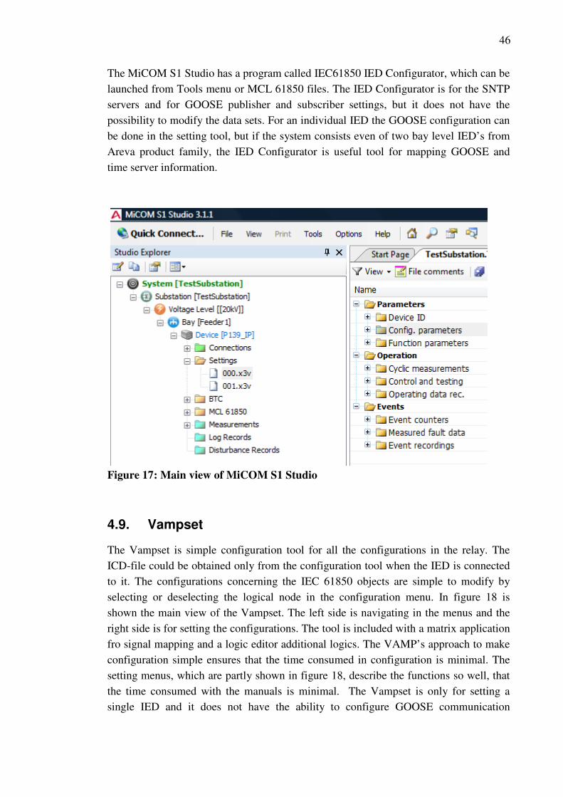
46
The MiCOM S1 Studio has a program called IEC61850 IED Configurator, which can be
launched from Tools menu or MCL 61850 files. The IED Configurator is for the SNTP
servers and for GOOSE publisher and subscriber settings, but it does not have the
possibility to modify the data sets. For an individual IED the GOOSE configuration can
be done in the setting tool, but if the system consists even of two bay level IED’s from
Areva product family, the IED Configurator is useful tool for mapping GOOSE and
time server information.
Figure 17: Main view of MiCOM S1 Studio
4.9. Vampset
The Vampset is simple configuration tool for all the configurations in the relay. The
ICD-file could be obtained only from the configuration tool when the IED is connected
to it. The configurations concerning the IEC 61850 objects are simple to modify by
selecting or deselecting the logical node in the configuration menu. In figure 18 is
shown the main view of the Vampset. The left side is navigating in the menus and the
right side is for setting the configurations. The tool is included with a matrix application
fro signal mapping and a logic editor additional logics. The VAMP’s approach to make
configuration simple ensures that the time consumed in configuration is minimal. The
setting menus, which are partly shown in figure 18, describe the functions so well, that
the time consumed with the manuals is minimal. The Vampset is only for setting a
single IED and it does not have the ability to configure GOOSE communication

47
between several relay simultaneously. The GOOSE settings are applied to ICD-files,
and it is possible to configure the relay with a CID-file.
Figure 18: Main view of Vampset configuration tool
The configured ICD-file of the VAMP52 had a small issue with the PACiS SCE.
The file was valid and the IEC 61850 mappings were mapped correctly, but because the
generation process uses the imported ICD-files, the generating process while converting
the file created an overflow error. The error was caused by report control definition in
the ICD-file. Since the demo-system is small only one data set was needed for MMS
reporting, the non-used report control definitions were deleted manually from the ICD-
file. In the appendix B is shown a part of the VAMP52 ICD-file and the deleted lines
are highlighted in red. This way the C264 database could be generated and all
configurations worked correctly. The VAMP’s approach to the ICD-file is to avoid
unnecessary information and keep the SCL files small, which saves time from the
station computer configuration in several stages.

48
4.10. WinConfig GOOSE light
The REG-DA is a voltage regulator and it is more focused device than a modern
protective relay. A voltage regulator does not have to have same kind of levels of
functionality and formability, thus the manufacturer can preconfigure the device more
accurately.
The WinConfig GOOSE light works trough an internet browser. The interface
layout is similar to several other configuration tools. The figure 19 show the main view
opened with Windows Explorer. The left side is for navigation and right side is for
setting the configuration. Trough the web browser the REG-DA can be also monitored
and configured in real time. All configurations can also be done in offline mode. The
ICD-file can be exported from the WinConfig tool, but the file was also offered
beforehand.
The REG-DA voltage regulator was tested for interoperability with the C264
bay computer by AREVA T&D. In the demo-system the REG-DA did not have lot of
signals and because of that the configuration was easy and no real problems occurred.
The only minor problem was that the selected model only supported IEC 61850
communication via optic connectors and at first the communication was not working
due to wrong kind of optic wires. With copper wires such problems would not occur.
Figure 19: Main view of WinConfig GOOSE light configuration tool

49
4.11. PCM600 and CCT600
The REF615 is fully native IEC 61850 IED, which means that the IED has been
designed to without any internal protocol conversion. All configuration objects are
named by the IEC 61850 logical names in the PCM600 and CCT600 configuration
tools, which is a good solution since the IEC 61850 mappings are relatively simple to
understand and unambiguous. Because the IEC 61850 names do not open the meaning
of the functions, the manuals and description lists has to be used quite often. Both
PCM600 and CCT600 are new programs developed to support IEC 61850
communication and both support system configuration. Although the tools are versatile,
the tools are easy and fast to use. The PCM600 and CCT600 tools exchange information
with SCL-files as exhibited in figure 12.
The CCT600 is tool for communication configurations. With the tool it is
possible to modify the IED’s data sets, Report control blocks, and Goose configuration
and create new ones or delete unnecessary ones. The CCT600 can also consume and
modify other vendor’s ICD- and CID-files and add them to the system configuration. It
is also possible to configure other vendors CID-files. This is a very useful feature for
viewing the ICD- or CID-files in a more comprehensive interface. The CCT600 is also
for Gateway configurations, but since it was not included in the demo system, it is
outside the scope of this paper. The figure 20 shows an example view of the CCT600
tool.
Figure 20: Main view of CCT600 system configuration tool

50
The PCM600 is a simple tool for e IED’s settings configurations. The figure 21
shows an example view of the PCM600 tool. The default view is similar to other IED
setting software. The right side is for navigation, the left side is for object properties and
the middle is for matrix tool and for parameter setting window. The PCM600 is not
enough to set up an IED for a working system, since it does not have the possibility to
configure GOOSE communication. The IED ICD-file has to be exported from the
PCM600 and imported to CCT600. The data set for GOOSE has to be created and
communication configured correctly. The GOOSE settings can be transported to
PCM600 by exporting the SCD-file from CCT600 and importing it to PCM600.
Figure 21: Main view of PCM600 IED configuration tool
In the demo-system the REF615 had few interoperation problems with the C264.
The first problem was that the REF615 ICD-file, included with report control block
definitions, did not import to the PACiS. The problem was caused by a missing report
control block definition: Report ID (rptID). The problem was solved by adding the
attribute to the ICD-file with the CCT600 tool. Second problem was that the full ICD-
file, with all description from REF615, created an error during configuration generation
with PACiS SCE. This problem was fixed by deleting unnecessary logical nodes and
report settings with the CCT600 tool. The third problem was that, the devices did not
exchanged MMS read and write services. The connection was established between the
devices, but the devices did not exchange MMS services. The problem was not solved
during the configuration of the demo-system. Since GOOSE communication did not
have any problems, the whole REF615 communication was executed with GOOSE.

51
4.12. Other useful tools
Because the standard is new and the IEC 61850 devices do not always interoperate as
planned, some debugging tools are necessary. There is some free software available in,
which are useful. The following introduces few software tools, which were used for
debugging and tracing problem spots during the configuration of the demo-system.
MMS-Etherreal tool is useful tool for reading MMS and GOOSE messages from
the Ethernet bus. The MMS-Etherreal tool is free software and can be freely
downloaded from the internet. The tool is useful for reading and debugging the
communication between devices. By connecting a Ethernet hub, which simply copies all
incoming messages to all of its ports, between two IED’s, the communication between
the devices can be copied to an external port for example for an PC’s Ethernet port. The
GOOSE messages can be read with an Ethernet switch as well, since the GOOSE
messages are sent as multicast.
The windows operating system’s ping-tool is useful for checking the Ethernet
connection between the IED and the PC. If connection is missing between a
configuration tool and an IED, the communication settings and communication wires
should be checked.
The Omicron IED scout tool has a free version, which can be used for opening
SCL-files and for monitor status changes in an IED. The Omicron IED scout tool only
needs the IP-address of the IED to read the IEC 61850 mappings from the IED. With
the tool the status changes inside an IED can be read by updating the attribute. The tool
is very useful in situations when a status is changed in bay level device, but is not
updated to the SCADA. If the status change can be read with the IED scout from the
bay level device the configuration problem is with the gateway device.

52
5. EXPERIENCES FROM TESTING MULTI-VENDOR SYSTEM
5.1. Configuration experiences
Because the standard is new and differences relatively radically from earlier standards,
the devices with IEC 61850 still suffer from small issues. Naturally the IED’s from
same manufacturer do not have interoperation problems, but the configuration of a
multi-vendor substation automation system involves lot of problem solving. This entire
chapter includes experiences gained during the demo-system configuration and suggests
some improvements. Most of the problems are already introduces in chapter four. All of
the problems that occurred during the configuration were not significant, but the
debugging takes time, since the devices do not have specially designed tools for
debugging interoperation problems.
All devices in the demo system need their own configuration tools. Learning to
use all configuration tools takes a lot of time and effort. The manuals for the IED’s by
themselves consist several thousand pages. The demo-system includes five different
devices and total of eight different configuration tools from which six main tool are
described in chapter four.
The demo system, described more detailed in chapter 4.2, has one bay computer,
three protective relays and one voltage regulator. The relays and the regulator
communicate with MMS and GOOSE to the bay computer. The first step when starting
this kind of configuration is to import the ICD-files to the bay computer tool. There are
different approaches with manufacturers how the ICD-file can be obtained. Usually it is
possible to have the ICD-file before the IED, but in some it is only possible to have the
ICD-file from the devices configuration tool after the devices existing configuration has
been downloaded to the tool. In the first case the ICD-file can be considered to be static
and in the second case the ICD-file can be considered to be dynamic. Both solutions
have their benefits and disadvantages.
It is also useful to keep in mind the difference of the ICD and CID-file, since
manufacturers have a little bit different approaches with these files. The content of the
files vary, because the IED’s are usually preconfigured by the manufacturer up to some
point. For this reason the difference between an ICD and a CID-file is indistinct.
Sometimes it is useful to use the CID-file instead of the ICD-file, because in some cases
the basic ICD-file does not include all needed information for the IED that acts as a
client.

53
5.2. Static or dynamic ICD-file
The largest disadvantage of the static ICD-file is the file size. A static ICD-file contains
all IEC 61850 logical nodes and all other description. Often most of the described
information is not needed and makes configuration more cumbersome. If the ICD-file
describes a complex IED, sometimes the size of the file can cause some problems as
described in chapter 4.10. The processing times for the file also increases when file is
unnecessary large. The processing time includes, in the case PACiS software, validation
and IEC mapping. At first the bay computer configuration tool has to validate the ICD-
file in order to ensure that the imported file valid according to the SCL-schema. The
next step is to process the description and map the IEC 61850 objects. The mapping
stage is a critical point where the MMS-communication is defined to the bay computer
and if manufacturers have slightly different perceptions about the standard, some
problems may occur.
A dynamic ICD-file is usually easier to import to the system and the problems
spots are easily discovered, because the point of the dynamic file is to keep the file as
simple as possible to avoid problems caused by file size or complexity. The only
problem in this kind optimization is that it emphasized the importance of planning the
working system before IED configuration. If the system plans are done carelessly and
some functions or logical nodes has to be added to the system, a new ICD-file with the
added function has to be imported to the system. Usually this means reconfiguration
work in several different steps. The VAMP52’s ICD-file is by default fairly empty, and
needed logical nodes has to be first added to the working configuration before the ICD-
file should be exported from the VAMPSET.
The best solution for the ICD-file would be a predefined dynamic file that can be
modified easily by the IED’s configuration tool. The ICD-file should be able to be
modified with IED configuration tool, because it ensures that the IED has exactly the
same IEC 61850 description than the ICD-file which is consumed by other tools. This
way the ICD-file can be modified due to interoperation problems with a simple
interface. The possibility of a modification error would be reduced, since the
configuration engineers would not have to manually modify the files.
5.3. The use of generic I/O’s
The standard allows the manufacturers to use the logical node GGIO, which stands for
generic process I/O. The GGIO is intended to be used in the situation when an input or
output is not covered by the standard. In the current IED’s the GGIO is used relatively
much to map different information. The use of GGIO’s has its benefits and drawbacks.
If GGIO a logical node is used without a prefix, it does not have any logical meaning,
because the logical node GGIO does not signify a corresponding logical function. The
general use of the GGIO is not recommended, because it is not what the standard
intended. Usually the GGIO’s are mapped to represent actual free inputs or output in the

54
device. The manufacturers use the GGIO also to map virtual signals of an IED, which
then can be used for example for internal logics. Because the standard does not describe
all specific information that manufacturers want to transmit, the GGIO has become a
sort of a dump logical node, instead of creating new logical nodes, which would
describe the function more accurately.
The GGIO is useful in situations when an IED’s input or output function is not
the intended type that has been designed for the system. Different manufacturer’s
protective relays use the same logical nodes, but the attributed are not always the same
type. For example to change setting croup the attribute can be singlepoint control,
doublepoint control or multi point control. To keep the control commands consistent for
every device, sometimes GGIO has to be used, because it is the only way to get the data
point in right type to SCADA. In the demo system the GGIO’s had to be used in several
points, because in some cases the signal could not be modified correctly at the bay
computer. One solution would be to map the signal as defined in IED’s, and to keep the
SCADA commands consistent, map the signals as designed at the SCADA end.
The GGIO’s importance may reduce after process level IED’s become more
common. This means that the amount of physical inputs and outputs will reduce. All
connections are virtual connections, which communicate through the common
communication line. The second version of the IEC 61850 standard has more
predefined logical nodes, which should strengthen the proper use of the standard.
5.4. Goose mapping
To configure few GOOSE messages for a small system is not an issue, but for larger
system some kind of configuration tool to configure all devices in the working system is
necessary. Since GOOSE configuration is at least partly up to the device user, the
manufacturers can not preconfigure the GOOSE communication to IED’s completely.
To use interlocking between IED’s within a large system each IED has to be aware of
the GOOSE configuration in other IED’s. GOOSE messages are published constantly to
every port in the same network, the subscribing IED has to be configured to read the
message from the dataflow and use it as designed.
In the demo-system the GOOSE messaging system was successfully
demonstrated by sending the GOOSE signals to the bay computer from the other IED’s.
Two instances of residual overvoltage trips were sent from the protection IED’s and
shown with LED’s in the bay computer. The GOOSE data-sets did have the content
defined in the signal list in the appendix A, but only the residual overvoltage instances
were used in the demo-system. Horizontal GOOSE was not demonstrated, because
every device did not support the ability to show the received GOOSE in the devices
front display leds.

55
5.5. The debug schema
The figure 22 shows the debug schema that actualized during the demo-system
configuration. The figure 22 states that the ICD-files can be exported from the IED
configuration tool for PACiS SCE. Error or configuration fault may lead to
reconfiguration in the C264 bay computer configuration or in the IED’s configuration.
Sometimes the error correction had to be done manually altering the ICD-file with
XML-editor. If some correction was done to the ICD-files, it meant for a modification
in the C264 configuration, which adds the time consumed with configuration
significantly.
Figure 22: A simplified IEC 61850 demo-system debug schema. The green lines
illustrate the flow of ICD-files. The blue lines illustrate the flow of C264
configuration file. The red lines illustrate error or the need of reconfiguration. The
error correction can be done in several places depending on the problem. The back
line illustrates a running configuration.
P139 REF615 REG-DA VAMP52 IED’s
IED Configuration tools
MiCOM S1
Studio
PCM600 GOOSElight
Vampset
CCT600
PACiS SCE
Computer
maintenance tool
ICD-files
Or
C264
Configuration
not working as
designed
System not working as
designed
C264 Station computer
XML-editor

56
6. CONCLUSION
The new international substation standard IEC 61850 is reforming substation
automation. Technologies such as TCP/IP, Ethernet and low-cost high-performance
computers have enabled a new kind of approaches for substation automation. Since the
limitation of the bandwidth no longer exists, vast amounts of data can be moved through
the station bus. The standard offers predefined communication with predefined
functionality, compatibility between different manufacturers and less hard wiring and
several other benefits. The most crucial benefit is that the standard supports substation
automations future needs.
The new standard has a lot of benefits compared to earlier solutions, but because
of the differences to earlier solutions, the standard is suffering from small
implementation issues. The small issues do not affect how the devices work in systems
constructed from one manufacturer’s IED’s. In multi-vendor system the devices, which
has not been tested for interoperability, in great probability will have compatibility
problems. The amount of small implementation issues will undoubtedly decrease and
more serious problems should disappear in time after the manufacturers get more
experience and expertise. The amount of interoperation problems suggests that the
standard may allow too much implementation freedom for the manufacturers. An
additional standard which would list all know issue areas and offer solution, could
ensure better interoperability. Such standards are already in use in other industries,
which need standardization for interoperability.
The IEC 61850 is praised to improve several aspects in substation automation.
One aspect is to make configuration easy and less time consuming. The configuration
time is an important benefit of the IEC 61850, but it has not yet been realised, because
of the interoperation problems. While working with the demo-system, the time
consumed in debugging the compatibility error was several times over the actual
configuring device time. The devices, which had been tested before together, were easy
and quick to add in the working system, but with every device which had not been
tested, problems were encountered. Most of the problems were caused by the SCL-files
during the bay computer configuration, except one problem with MMS communication,
which was not solved during this work. During the demo-system configuration mainly
ICD-files were used, but most likely other SCL-files would cause similar problems if
they were used in multivendor-system configuration. GOOSE communication worked
without any real problems between the devices, which good for the success of the
demo-system, because the GOOSE communication was in major role in the demo.

57
REFERENCES
[1] IEC 61850-1. 2003. Communication networks and systems in substations – Part 1: Introduction and Overview. IEC. 37 p.
[2] Tholomier, D. Chatrefou, D. 2008. IEC 61850 Process Bus - It is Real! [Used:
5.10.2009] Available at: http://www.pacw.org/fileadmin/doc/WinterIssue08/protection_61850_winter08.pdf
[3] Proudfoot, D. 2002. UCA and 61850 for dummies. Siemens Power
Transmission & Distribution.
[4] IEC 61850-7-3. 2003. Communication networks and systems in substations – Part 7-3: Basic communication structure for substation and feeder equipment – Common data classes. IEC. 64 p.
[5] IEC 61850-7-4. 2003. Communication networks and systems in substations – Part 7-4: Basic communication structure for substation and feeder equipment – Compatible logical node classes and data classes. IEC. 104 p.
[6] IEC 61850-8-1. 2004. Communication networks and systems in substations –
Part 8-1: Specific Communication Service Mapping (SCSM) – Mappings to MMS (ISO 9506-1 and ISO 9506-2) and to ISO/IEC 8802-3. IEC. 133 p.
[7] IEC 61850-9-1. 2003. Communication networks and systems in substations – Part 9-1: Specific Communication Service Mapping (SCSM) – Sampled values over serial unidirectional multidrop point to point link. IEC. 29 p.
[8] IEC 61850-9-2. 2004. Communication networks and systems in substations – Part 9-2: Specific Communication Service Mapping (SCSM) – Sampled values over ISO/IEC 8802-3. IEC. 28 p.
[9] Mackiewicz R. Technical Overview and Benefits of the IEC 61850 Standard for
Substation Automation. 8 p. [10] IEC 61850-7-1. 2003. Communication networks and systems in substations –
Part 7-1: Basic communication structure for substation and feeder equipment –
Principles and models. IEC. 110 p.
[11] Baigent, D. Adamiak, M. Mackiewicz, R. 2004. IEC 61850 Communication
Networks and Systems In Substations: An Overview for Users, SIPSEP
Monterrey, Nuevo León, México Miércoles. [Used: 28.7.2009] Available at:
http://www.sisconet.com/downloads/SIPSEP%202004%20IEC%2061850%20P
anel%20Presentation%20-%20SISCO.ppt

58
[12] IEC 61850-5. 2003. Communication networks and systems in substations – Part 5: Communication requirements for functions and device models. IEC. 131 p.
[13] Overview and Introduction to the Manufacturing Message Specification (MMS).
[Used: 29.7.2009] Available at: http://www.sisconet.com/downloads/mmsovrlg.pdf
[14] Brand, K-P, Senior Member, IEEE. The Standard IEC 61850 as Prerequisite for
Intelligent Application in Substations.
[15] Tarlochan, S. Mitalkumar G. Palak P. 2008. Implementation Issues with IEC 61850 Based Substation Automation Systems. Fifteenth National Power Systems Conference (NPSC), IIT Bombay, December 2008.
[16] Lars Andersson, Klaus-Peter Brand, Dieter Fuechsle. 2008. Optimized
Architectures for process bus with IEC 61850-9-2. Cigre Session 2008. [17] Ozansoy, C. Zayegh, A. Kalam, A. 2009. Object Modeling of Data and DataSets
in the International Standard IEC 61850. IEEE Transactions on power systems, Vol. 24, No. 3, July 2009. pp 1140-1147.
[18] IEC 61850-7-2. 2003. Communication networks and systems in substations –
Part 7-2: Basic communication structure for substation and feeder equipment – Abstract communication service interface (ACSI). IEC. 171 p.
[19] Schwarz, K. Introduction to the Manufacturing Message Specification (MMS,
ISO/IEC 9506). [Used: 2.3.2010] Available at:
http://www.nettedautomation.com/standardization/ISO/TC184/SC5/WG2/mms_
intro/
[20] Hou, D. Dolezilek, D. Schweitzer Engineering Laboratories, Inc. IEC 61850 – What It Can and Cannot Offer to Traditional Protection Schemes [Used: 3.8.2009] Available at: http://www.selinc.com/WorkArea/DownloadAsset.aspx?id=3546
[21] Zhang, L, X. Nair, N-M, C. 2008. Testing Protective Relays in IEC 61850
Framework. 2008 Australasian Universities Power Engineering Conference
(AUPEC'08).
[22] Brand, K-P. Janssen, M. The specification of IEC 61850 based substation automation systems.
[23] Dreher, A. Mohl, D. Precision Clock Synchronization - The Standard IEEE
1588. [Used: 4.8.2009] Available at: http://www.pes-psrc.org/h/HTF1_Presentation_1_1588_Skendzic.pdf
59
[24] Kasztenny, B. Whatley, J. Udren, E. Burger, J. Finney, D. Adamiak, M. 2006. IEC 61850 - A Practical Application Primer for Protection Engineers. [Used: 20.2.2010] Available at: http://www.gedigitalenergy.com/multilin/pr/GaTech/2006/IEC61850_Practical_Application_Primer_Protection_Eng.pdf
[25] IEC 61850-6. 2004. Communication networks and systems in substations – Part
6: Configuration description language for communication in electrical substation
related to IEDs. IEC. 144 p.
[26] Goraj, M. Herrmann, J. 2007. Experience in IEC 61850 and possible improvements of SCL language. [Used: 1.10.2009] Available at: http://www.sisconet.com/downloads/GE_E_2007.pdf
[27] Andersson, L. Brand, K-P. Brunner, C. Wimmer, W. 2005. Reliability investigations for SA communication architectures based on IEC 61850. Presented as Paper 604 in the Poster Session at 2005 IEEE St.Petersburg PowerTech, June 27-30, St.Petersburg, Russia.
[28] Skendzic, V. Moore, R. Extending the Substation LAN Beyond Substation Boundaries: Current Capabilities and Potential New Protection Applications of Wide-Area Ethernet.
[29] Coates, G. Hopkinson, K. Graham, S. Stuart H. Kurkowski, S. 2008.
Collaborative, Trust-Based Security Mechanisms for a Regional Utility Intranet. IEEE Transactions on power systems, Vol. 23, No. 3, August 2008. pp 831-844.
[30] Syöttötariffityöryhmän loppuraportti, Ehdotus tuulivoimalla ja biokaasulla
tuotetun sähkön syöttötariffiksi, Pupliched: November 2009, Publications of the Ministry of Employment and the Economy, Energy and Climate, Available at: http://www.tem.fi/files/25308/TEMjul_59_2009_energia.pdf
[31] The Finnish Wind Power Association. briefing 15.6.2009. [Used: 24.9.2009]
Available at: http://www.tuulivoimayhdistys.fi/tiedotteet
[32] Wind energy statistics in Finland. [Used: 24.9.2009] Available at:
http://www.vtt.fi/proj/windenergystatistics/index.jsp
[33] Schwarz, K. 2004. IEC 61850, IEC 61400-25, IEC 61970: Information models
and information exchange for electric power systems. [Used: 24.8.2009]
Available at: http://nettedautomation.com/download/Paper_IEC61850_Distribu
tech_2004-02-10.pdf
[34] Johnsson, A. Højholt, L. Use of IEC 61400-25 to secure access to key O&M
data. [Used: 24.9.2009] Available at:
http://www.eow2007proceedings.info/allfiles2/170_Eow2007fullpaper.pdf

60
[35] Schwarz, K. 2004. Advanced Condition Monitoring of Primary Equipment with the Standard Series IEC 61850 AND IEC 61400-25. [Used: 23.9.2009] Available at: http://www.cepsi2008.org/CEPSI2008/files/oral/26/full_paper_karlheinz_schwarz.pdf
[36] Hunt, R. Cardenas, J. Muthukrishnan, V. McGinn, D. 2010. Wind Farm
Protection Using an IEC 61850 Process Bus Architecture. [Used: 20.5.2010] Available at: http://www.dtechspeakers.com/etc/medialib/distributech/documents.Par.88688.File.dat/Sample%20Manuscript.pdf
[37] Lauri, P. 2010. UTU Elec Oy. E-mail 19.5.2010 [38] ABB, REF615 manual, IEC 61850 - 615 series Engineering Guide. [39] Areva, PACiS SCE System Configuration Editor Technical Guide. [40] Areva, MiCOM C264/C264C Bay Computer Technical Guide

61
APPENDIX A - Signal list for the IEC 61850 demo-system
C264
Signal Areva
Type Bay Computer SPS 1001 Position/Event Din1 0/1
SPS 1002 Position/Event Din2 0/1
SPS Count active power pulses Di3
SPS Count reactive power pulses Di4
Goose Led4 Show goose
Goose Led5 Show goose
Goose Led6 Show goose
Goose Led7 Show goose
Goose Led8 Show goose
Goose Led9 Show goose
Goose Led10 Show goose
Goose Led11 Show goose
Goose Led12 Show goose
Goose Led13 Show goose
Goose Led14 Show goose
Goose Led15 Show goose
Goose Led16 Show goose
MV 1030 Voltage Uo C264
MV Disp2 Voltage Uo P139
MV Disp2 Voltage Uo VAMP52
MV Disp2 Voltage Uo REF
MV Disp2 Voltage Uo 7SJ62
MV Disp2 Voltage U REG DP
SPS/MV Disp1 Alarm Di1 C264
SPS/MV Disp1 Alarm Di2 C264
SPS/MV Disp1 Alarm Di7 P139
SPS/MV Disp1 Alarm Di8 P139
SPS/MV Disp1 Alarm Di7 REF
SPS/MV Disp1 Alarm Di8 REF
SPS/MV Disp1 Alarm Di7 7SJ62
SPS/MV Disp1 Alarm Di8 7SJ62
SPS/MV Disp1 Alarm Di7 REG
SPS/MV Disp1 Alarm Di8 REG
X/MV Disp3 P139 mimic
X/MV Disp4 VAMP52 mimic
X/MV Disp5 REF mimic
X/MV Disp6 7SJ62 mimic
X/MV Disp5 REG mimic
MV 1031 Active power pulses in Di3
MV 1032 Reactive power pulses in Di4
DPC 1050 Set All Local/Remote LS=1 RS=2 LRE=3
SPC 1051 Send Energy pulses to SCADA=1 (Di3&4)
SPC 1052 All Protection to Main setup=0 Backr s=1
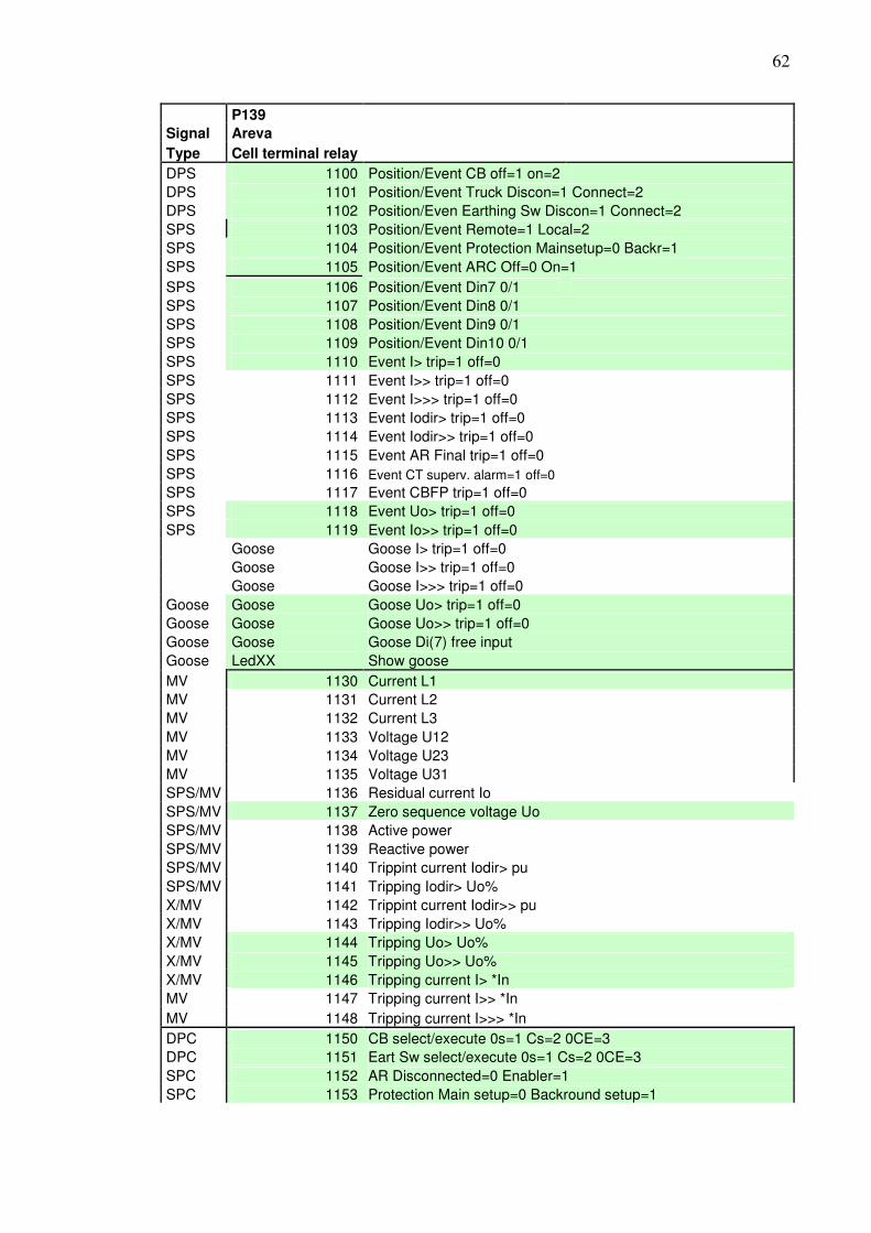
62
P139
Signal Areva
Type Cell terminal relay DPS 1100 Position/Event CB off=1 on=2
DPS 1101 Position/Event Truck Discon=1 Connect=2
DPS 1102 Position/Even Earthing Sw Discon=1 Connect=2
SPS 1103 Position/Event Remote=1 Local=2
SPS 1104 Position/Event Protection Mainsetup=0 Backr=1
SPS 1105 Position/Event ARC Off=0 On=1
SPS 1106 Position/Event Din7 0/1
SPS 1107 Position/Event Din8 0/1
SPS 1108 Position/Event Din9 0/1
SPS 1109 Position/Event Din10 0/1
SPS 1110 Event I> trip=1 off=0
SPS 1111 Event I>> trip=1 off=0
SPS 1112 Event I>>> trip=1 off=0
SPS 1113 Event Iodir> trip=1 off=0
SPS 1114 Event Iodir>> trip=1 off=0
SPS 1115 Event AR Final trip=1 off=0
SPS 1116 Event CT superv. alarm=1 off=0
SPS 1117 Event CBFP trip=1 off=0
SPS 1118 Event Uo> trip=1 off=0
SPS 1119 Event Io>> trip=1 off=0
Goose Goose I> trip=1 off=0
Goose Goose I>> trip=1 off=0
Goose Goose I>>> trip=1 off=0
Goose Goose Goose Uo> trip=1 off=0
Goose Goose Goose Uo>> trip=1 off=0
Goose Goose Goose Di(7) free input
Goose LedXX Show goose
MV 1130 Current L1
MV 1131 Current L2
MV 1132 Current L3
MV 1133 Voltage U12
MV 1134 Voltage U23
MV 1135 Voltage U31
SPS/MV 1136 Residual current Io
SPS/MV 1137 Zero sequence voltage Uo
SPS/MV 1138 Active power
SPS/MV 1139 Reactive power
SPS/MV 1140 Trippint current Iodir> pu
SPS/MV 1141 Tripping Iodir> Uo%
X/MV 1142 Trippint current Iodir>> pu
X/MV 1143 Tripping Iodir>> Uo%
X/MV 1144 Tripping Uo> Uo%
X/MV 1145 Tripping Uo>> Uo%
X/MV 1146 Tripping current I> *In
MV 1147 Tripping current I>> *In
MV 1148 Tripping current I>>> *In
DPC 1150 CB select/execute 0s=1 Cs=2 0CE=3
DPC 1151 Eart Sw select/execute 0s=1 Cs=2 0CE=3
SPC 1152 AR Disconnected=0 Enabler=1
SPC 1153 Protection Main setup=0 Backround setup=1

63
52
Signal VAMP
Type Feeder and motor protection relay
DPS 1200 Position/Event CB off=1 on=2
SPS 1203 Position/Event Remote=1 Local=2
SPS 1204 Position/Event Protection Mainsetup=0 Backr=1
SPS 1205 Position/Event ARC Off=0 On=1
SPS 1210 Event I> trip=1 off=0
SPS 1211 Event I>> trip=1 off=0
SPS 1212 Event I>>> trip=1 off=0
SPS 1213 Event Iodir> trip=1 off=0
SPS 1214 Event Iodir>> trip=1 off=0
SPS 1215 Event AR Final trip=1 off=0
SPS 1216 Event CT superv. alarm=1 off=0
SPS 1217 Event CBFP trip=1 off=0
SPS 1218 Event Uo> trip=1 off=0
SPS 1219 Event Io>> trip=1 off=0
Goose Goose I> trip=1 off=0
Goose Goose I>> trip=1 off=0
Goose Goose I>>> trip=1 off=0
Goose Goose Goose Uo> trip=1 off=0
Goose Goose Goose Uo>> trip=1 off=0
Goose LedXX Show goose
MV 1230 Current L1
MV 1231 Current L2
MV 1232 Current L3
MV 1233 Residual current Io
MV 1234 Zero sequence voltage Uo
SPS/MV 1240 Trippint current Iodir> pu
SPS/MV 1241 Tripping Iodir> Uo%
X/MV 1242 Trippint current Iodir>> pu
X/MV 1243 Tripping Iodir>> Uo%
X/MV 1244 Tripping Uo> Uo%
X/MV 1245 Tripping Uo>> Uo%
X/MV 1246 Tripping current I> *In
MV 1247 Tripping current I>> *In
MV 1248 Tripping current I>>> *In
DPC 1250 CB select/executeB 0s=1 Cs=2 0CE=3
SPC 1252 AR Disconnected=0 Enabler=1
SPC 1253 Protection Main setup=0 Backround setup=1

64
REF615
Signal ABB
Type Feeder protection relay DPS 1300 Position/Event CB off=1 on=2
DPS 1301 Position/Event Truck Discon=1 Connect=2
DPS 1302 Position/Even Earthing Sw Discon=1 Connect=2
SPS 1303 Position/Event Remote=1 Local=2
SPS 1304 Position/Event Protection Mainsetup=0 Backr=1
SPS 1305 Position/Event ARC Off=0 On=1
SPS 1306 Position/Event Din7 0/1
SPS 1307 Position/Event Din8 0/1
SPS 1308 Position/Event Din9 0/1
SPS 1309 Position/Event Din10 0/1
SPS 1310 Event I> trip=1 off=0
SPS 1311 Event I>> trip=1 off=0
SPS 1312 Event I>>> trip=1 off=0
SPS 1313 Event Iodir> trip=1 off=0
SPS 1314 Event Iodir>> trip=1 off=0
SPS 1315 Event AR Final trip=1 off=0
SPS 1316 Event CT superv. alarm=1 off=0
SPS 1317 Event CBFP trip=1 off=0
SPS 1318 Event Uo> trip=1 off=0
SPS 1319 Event Io>> trip=1 off=0
Goose Goose I> trip=1 off=0
Goose Goose I>> trip=1 off=0
Goose Goose I>>> trip=1 off=0
Goose Goose Goose Uo> trip=1 off=0
Goose Goose Goose Uo>> trip=1 off=0
Goose Goose Goose Di(7) free input
Goose LedXX Show goose
MV 1330 Current L1
MV 1331 Current L2
MV 1332 Current L3
MV 1333 Voltage U12
MV 1334 Voltage U23
MV 1335 Voltage U31
SPS/MV 1336 Residual current Io
SPS/MV 1337 Zero sequence voltage Uo
SPS/MV 1338 Active power
SPS/MV 1339 Reactive power
SPS/MV 1340 Trippint current Iodir> pu
SPS/MV 1341 Tripping Iodir> Uo%
X/MV 1342 Trippint current Iodir>> pu
X/MV 1343 Tripping Iodir>> Uo%
X/MV 1344 Tripping Uo> Uo%
X/MV 1345 Tripping Uo>> Uo%
X/MV 1346 Tripping current I> *In
MV 1347 Tripping current I>> *In
MV 1348 Tripping current I>>> *In
DPC 1350 CB select/execute 0s=1 Cs=2 0CE=3
DPC 1351 Eart Sw select/execute 0s=1 Cs=2 0CE=3
SPC 1352 AR Disconnected=0 Enabler=1
SPC 1353 Protection Main setup=0 Backround setup=1

65
REG-DA
Signal A eberle
Type Voltage regulator SPS 900 Position/Event Remote=1 Local=2
SPS 901 Position/Event Man=0 Auto=1
SPS 902 Position/Event Setpoint Mainsetup=0 Backr=1
SPS 903 Position/Event Din2 0/1
SPS 904 Position/Event Din3 0/1
SPS 905 Position/Event Din4 0/1
SPS 910 Event I> trip=1 off=0 (block operation)
SPS 911 Event Regulator fault
SPS 912 Event Tap changer doesn't work
Goose Goose I> trip=1 off=0
Goose LedXX Show goose
Goose Goose Goose Di2
Goose Goose Goose Di3
MV 930 Position of the OLTC
SPC 950 Manual=0 Auto=1
SPC 951 Voltage Lower=1
SPC 952 Voltage Raise=1
SPC 953 Setup Main setup=0 Backround setup=1

66
APPENDIX B -VAMP52 ICD-file debug <?xml version="1.0" encoding="UTF-8"?>
<!--This file is generated using INFO TECH IEC61850 Server Configuration Tool (www.infotech.pl)-->
<SCL xmlns="http://www.iec.ch/61850/2003/SCL" xmlns:xsi="http://www.w3.org/2001/XMLSchema-instance"
xsi:schemaLocation="http://www.iec.ch/61850/2003/SCL SCL.xsd">
<Header id="INFO TECH SCL" nameStructure="IEDName"/>
<Communication>
<SubNetwork name="NONE">
<ConnectedAP iedName="VAMP52T4" apName="P1">
<Address>
<P type="OSI-AP-Title">1,3,9999,33</P>
<P type="OSI-AE-Qualifier">1</P>
<P type="OSI-PSEL">00000001</P>
<P type="OSI-SSEL">0001</P>
<P type="OSI-TSEL">0001</P>
<P type="IP">10.10.10.4</P>
<P type="IP-SUBNET">255.255.255.0</P>
<P type="IP-GATEWAY">0.0.0.0</P>
</Address>
<GSE ldInst="Relay" cbName="gcb1">
<Address>
<P type="VLAN-ID">0</P>
<P type="VLAN-PRIORITY">4</P>
<P type="MAC-Address">01-0C-CD-01-00-00</P>
<P type="APPID">4</P>
</Address>
</GSE>
<GSE ldInst="Relay" cbName="gcb2">
<Address>
<P type="VLAN-ID">0</P>
<P type="VLAN-PRIORITY">4</P>
<P type="MAC-Address">01-0C-CD-01-00-00</P>
<P type="APPID">1</P>
</Address>
</GSE>
</ConnectedAP>
</SubNetwork>
</Communication>
<IED name="VAMP52T4" type="VAMP 52" manufacturer="VAMP Ltd." configVersion="0.0.1">
<Services>
<DynAssociation/>
<GetDirectory/>
<GetDataObjectDefinition/>
<DataObjectDirectory/>
<GetDataSetValue/>
<SetDataSetValue/>
<DataSetDirectory/>
<ConfDataSet max="5" maxAttributes="150"/>
<DynDataSet max="16" maxAttributes="100"/>
<ReadWrite/>
<ConfReportControl max="6"/>
<ReportSettings bufTime="Conf" trgOps="Conf" cbName="Fix" rptID="Conf" datSet="Conf" intgPd="Conf"
optFields="Conf"/>
<GetCBValues/>

67
<GSEDir/>
<GOOSE max="2"/>
</Services>
<AccessPoint name="P1">
<Server>
<Authentication none="true"/>
<LDevice inst="Relay">
<LN0 lnType="LLN0_0" lnClass="LLN0" inst="">
<DataSet name="DS1">
<FCDA ldInst="Relay" prefix="AR1ft" lnClass="GGIO" lnInst="16" doName="Ind" fc="ST"/>
<FCDA ldInst="Relay" prefix="AR2ft" lnClass="GGIO" lnInst="17" doName="Ind" fc="ST"/>
<FCDA ldInst="Relay" prefix="AR3ft" lnClass="GGIO" lnInst="18" doName="Ind" fc="ST"/>
<FCDA ldInst="Relay" prefix="AR4ft" lnClass="GGIO" lnInst="19" doName="Ind" fc="ST"/>
<FCDA ldInst="Relay" prefix="AR5" lnClass="RREC" lnInst="1" doName="BlkRec" fc="ST"/>
<FCDA ldInst="Relay" prefix="AR5" lnClass="RREC" lnInst="1" doName="Op" fc="ST"/>
<FCDA ldInst="Relay" prefix="AR5" lnClass="RREC" lnInst="1" doName="AutoRecSt" fc="ST"/>
<FCDA ldInst="Relay" prefix="ARcft" lnClass="GGIO" lnInst="15" doName="Ind" fc="ST"/>
<FCDA ldInst="Relay" prefix="ARcre" lnClass="GGIO" lnInst="13" doName="Ind" fc="ST"/>
<FCDA ldInst="Relay" prefix="ARft" lnClass="GGIO" lnInst="14" doName="Ind" fc="ST"/>
<FCDA ldInst="Relay" prefix="ARloc" lnClass="GGIO" lnInst="2" doName="Ind" fc="ST"/>
<FCDA ldInst="Relay" prefix="ARre1" lnClass="GGIO" lnInst="3" doName="Ind" fc="ST"/>
<FCDA ldInst="Relay" prefix="ARre2" lnClass="GGIO" lnInst="4" doName="Ind" fc="ST"/>
<FCDA ldInst="Relay" prefix="ARre3" lnClass="GGIO" lnInst="5" doName="Ind" fc="ST"/>
<FCDA ldInst="Relay" prefix="ARre4" lnClass="GGIO" lnInst="6" doName="Ind" fc="ST"/>
<FCDA ldInst="Relay" prefix="ARre5" lnClass="GGIO" lnInst="7" doName="Ind" fc="ST"/>
<FCDA ldInst="Relay" prefix="ARrun" lnClass="GGIO" lnInst="1" doName="Ind" fc="ST"/>
<FCDA ldInst="Relay" prefix="ARsh1" lnClass="GGIO" lnInst="8" doName="Ind" fc="ST"/>
<FCDA ldInst="Relay" prefix="ARsh2" lnClass="GGIO" lnInst="9" doName="Ind" fc="ST"/>
<FCDA ldInst="Relay" prefix="ARsh3" lnClass="GGIO" lnInst="10" doName="Ind" fc="ST"/>
<FCDA ldInst="Relay" prefix="ARsh4" lnClass="GGIO" lnInst="11" doName="Ind" fc="ST"/>
<FCDA ldInst="Relay" prefix="ARsh5" lnClass="GGIO" lnInst="12" doName="Ind" fc="ST"/>
<FCDA ldInst="Relay" prefix="CBFP" lnClass="PIOC" lnInst="4" doName="Str" fc="ST"/>
<FCDA ldInst="Relay" prefix="CBFP" lnClass="PIOC" lnInst="4" doName="Op" fc="ST"/>
<FCDA ldInst="Relay" prefix="DEF1" lnClass="PTOC" lnInst="9" doName="Str" fc="ST"/>
<FCDA ldInst="Relay" prefix="DEF1" lnClass="PTOC" lnInst="9" doName="Op" fc="ST"/>
<FCDA ldInst="Relay" prefix="DEF2" lnClass="PTOC" lnInst="10" doName="Str" fc="ST"/>
<FCDA ldInst="Relay" prefix="DEF2" lnClass="PTOC" lnInst="10" doName="Op" fc="ST"/>
<FCDA ldInst="Relay" prefix="DI01" lnClass="GGIO" lnInst="45" doName="Ind" fc="ST"/>
<FCDA ldInst="Relay" prefix="DI02" lnClass="GGIO" lnInst="46" doName="Ind" fc="ST"/>
<FCDA ldInst="Relay" prefix="DI03" lnClass="GGIO" lnInst="47" doName="Ind" fc="ST"/>
<FCDA ldInst="Relay" prefix="DI04" lnClass="GGIO" lnInst="48" doName="Ind" fc="ST"/>
<FCDA ldInst="Relay" prefix="DI05" lnClass="GGIO" lnInst="49" doName="Ind" fc="ST"/>
<FCDA ldInst="Relay" prefix="DI06" lnClass="GGIO" lnInst="50" doName="Ind" fc="ST"/>
<FCDA ldInst="Relay" prefix="DI07" lnClass="GGIO" lnInst="51" doName="Ind" fc="ST"/>
<FCDA ldInst="Relay" prefix="DI08" lnClass="GGIO" lnInst="52" doName="Ind" fc="ST"/>
<FCDA ldInst="Relay" prefix="EF1" lnClass="PTOC" lnInst="4" doName="Str" fc="ST"/>
<FCDA ldInst="Relay" prefix="EF1" lnClass="PTOC" lnInst="4" doName="Op" fc="ST"/>
<FCDA ldInst="Relay" prefix="EF2" lnClass="PTOC" lnInst="5" doName="Str" fc="ST"/>
<FCDA ldInst="Relay" prefix="EF2" lnClass="PTOC" lnInst="5" doName="Op" fc="ST"/>
<FCDA ldInst="Relay" prefix="I3pda" lnClass="MMXU" lnInst="3" doName="A.phsA" fc="MX"/>
<FCDA ldInst="Relay" prefix="I3pda" lnClass="MMXU" lnInst="3" doName="A.phsB" fc="MX"/>
<FCDA ldInst="Relay" prefix="I3pda" lnClass="MMXU" lnInst="3" doName="A.phsC" fc="MX"/>
<FCDA ldInst="Relay" prefix="I3p" lnClass="MMXU" lnInst="1" doName="A.phsA" fc="MX"/>
<FCDA ldInst="Relay" prefix="I3p" lnClass="MMXU" lnInst="1" doName="A.phsB" fc="MX"/>
<FCDA ldInst="Relay" prefix="I3p" lnClass="MMXU" lnInst="1" doName="A.phsC" fc="MX"/>
<FCDA ldInst="Relay" prefix="I3pr" lnClass="MMXU" lnInst="2" doName="A.phsA" fc="MX"/>
<FCDA ldInst="Relay" prefix="I3pr" lnClass="MMXU" lnInst="2" doName="A.phsB" fc="MX"/>

68
<FCDA ldInst="Relay" prefix="I3pr" lnClass="MMXU" lnInst="2" doName="A.phsC" fc="MX"/>
<FCDA ldInst="Relay" prefix="IOC1" lnClass="GGIO" lnInst="142" doName="AnIn" fc="MX"/>
<FCDA ldInst="Relay" prefix="IOC2" lnClass="GGIO" lnInst="143" doName="AnIn" fc="MX"/>
<FCDA ldInst="Relay" prefix="IOC3" lnClass="GGIO" lnInst="144" doName="AnIn" fc="MX"/>
<FCDA ldInst="Relay" prefix="IoC" lnClass="MMXU" lnInst="13" doName="A.res" fc="MX"/>
<FCDA ldInst="Relay" prefix="LO01" lnClass="GGIO" lnInst="77" doName="Ind" fc="ST"/>
<FCDA ldInst="Relay" prefix="LO02" lnClass="GGIO" lnInst="78" doName="Ind" fc="ST"/>
<FCDA ldInst="Relay" prefix="LO03" lnClass="GGIO" lnInst="79" doName="Ind" fc="ST"/>
<FCDA ldInst="Relay" prefix="LO04" lnClass="GGIO" lnInst="80" doName="Ind" fc="ST"/>
<FCDA ldInst="Relay" prefix="LO05" lnClass="GGIO" lnInst="81" doName="Ind" fc="ST"/>
<FCDA ldInst="Relay" prefix="LO06" lnClass="GGIO" lnInst="82" doName="Ind" fc="ST"/>
<FCDA ldInst="Relay" prefix="Obj1" lnClass="CSWI" lnInst="1" doName="Pos" fc="ST"/>
<FCDA ldInst="Relay" prefix="Obj1" lnClass="RSYN" lnInst="1" doName="Rel" fc="ST"/>
<FCDA ldInst="Relay" prefix="Obj1" lnClass="RSYN" lnInst="1" doName="AngInd" fc="ST"/>
<FCDA ldInst="Relay" prefix="Obj1" lnClass="RSYN" lnInst="1" doName="SynPrg" fc="ST"/>
<FCDA ldInst="Relay" prefix="Obj2" lnClass="CSWI" lnInst="2" doName="Pos" fc="ST"/>
<FCDA ldInst="Relay" prefix="Obj2" lnClass="RSYN" lnInst="2" doName="Rel" fc="ST"/>
<FCDA ldInst="Relay" prefix="Obj2" lnClass="RSYN" lnInst="2" doName="AngInd" fc="ST"/>
<FCDA ldInst="Relay" prefix="Obj2" lnClass="RSYN" lnInst="2" doName="SynPrg" fc="ST"/>
<FCDA ldInst="Relay" prefix="Obj3" lnClass="CSWI" lnInst="3" doName="Pos" fc="ST"/>
<FCDA ldInst="Relay" prefix="OC1" lnClass="PTOC" lnInst="1" doName="Str" fc="ST"/>
<FCDA ldInst="Relay" prefix="OC1" lnClass="PTOC" lnInst="1" doName="Op" fc="ST"/>
<FCDA ldInst="Relay" prefix="OC2" lnClass="PTOC" lnInst="2" doName="Str" fc="ST"/>
<FCDA ldInst="Relay" prefix="OC2" lnClass="PTOC" lnInst="2" doName="Op" fc="ST"/>
<FCDA ldInst="Relay" prefix="OV1" lnClass="PTOV" lnInst="3" doName="Str" fc="ST"/>
<FCDA ldInst="Relay" prefix="OV1" lnClass="PTOV" lnInst="3" doName="Op" fc="ST"/>
<FCDA ldInst="Relay" prefix="OV2" lnClass="PTOV" lnInst="4" doName="Str" fc="ST"/>
<FCDA ldInst="Relay" prefix="OV2" lnClass="PTOV" lnInst="4" doName="Op" fc="ST"/>
<FCDA ldInst="Relay" prefix="PS1S" lnClass="GGIO" lnInst="29" doName="Ind" fc="ST"/>
<FCDA ldInst="Relay" prefix="PS1T" lnClass="GGIO" lnInst="37" doName="Ind" fc="ST"/>
<FCDA ldInst="Relay" prefix="PS2S" lnClass="GGIO" lnInst="30" doName="Ind" fc="ST"/>
<FCDA ldInst="Relay" prefix="PS2T" lnClass="GGIO" lnInst="38" doName="Ind" fc="ST"/>
<FCDA ldInst="Relay" prefix="PS3S" lnClass="GGIO" lnInst="31" doName="Ind" fc="ST"/>
<FCDA ldInst="Relay" prefix="PS3T" lnClass="GGIO" lnInst="39" doName="Ind" fc="ST"/>
<FCDA ldInst="Relay" prefix="SG1" lnClass="GGIO" lnInst="135" doName="SPCSO" fc="ST"/>
<FCDA ldInst="Relay" prefix="SG2" lnClass="GGIO" lnInst="136" doName="SPCSO" fc="ST"/>
<FCDA ldInst="Relay" prefix="U3p" lnClass="MMXU" lnInst="4" doName="PhV.phsA" fc="MX"/>
<FCDA ldInst="Relay" prefix="U3p" lnClass="MMXU" lnInst="4" doName="PhV.phsB" fc="MX"/>
<FCDA ldInst="Relay" prefix="U3p" lnClass="MMXU" lnInst="4" doName="PhV.phsC" fc="MX"/>
<FCDA ldInst="Relay" prefix="Uo1" lnClass="PTOV" lnInst="1" doName="Str" fc="ST"/>
<FCDA ldInst="Relay" prefix="Uo1" lnClass="PTOV" lnInst="1" doName="Op" fc="ST"/>
<FCDA ldInst="Relay" prefix="Uo2" lnClass="PTOV" lnInst="2" doName="Str" fc="ST"/>
<FCDA ldInst="Relay" prefix="Uo2" lnClass="PTOV" lnInst="2" doName="Op" fc="ST"/>
<FCDA ldInst="Relay" prefix="Uo" lnClass="MMXU" lnInst="10" doName="PhV.neut" fc="MX"/>
<FCDA ldInst="Relay" prefix="VI1" lnClass="GGIO" lnInst="137" doName="SPCSO" fc="ST"/>
<FCDA ldInst="Relay" prefix="VI2" lnClass="GGIO" lnInst="138" doName="SPCSO" fc="ST"/>
<FCDA ldInst="Relay" prefix="VI3" lnClass="GGIO" lnInst="139" doName="SPCSO" fc="ST"/>
<FCDA ldInst="Relay" prefix="VI4" lnClass="GGIO" lnInst="140" doName="SPCSO" fc="ST"/>
<FCDA ldInst="Relay" prefix="VO1" lnClass="GGIO" lnInst="97" doName="Ind" fc="ST"/>
<FCDA ldInst="Relay" prefix="VO2" lnClass="GGIO" lnInst="98" doName="Ind" fc="ST"/>
<FCDA ldInst="Relay" prefix="VO3" lnClass="GGIO" lnInst="99" doName="Ind" fc="ST"/>
<FCDA ldInst="Relay" prefix="VO4" lnClass="GGIO" lnInst="100" doName="Ind" fc="ST"/>
<FCDA ldInst="Relay" prefix="VO5" lnClass="GGIO" lnInst="101" doName="Ind" fc="ST"/>
<FCDA ldInst="Relay" prefix="VO6" lnClass="GGIO" lnInst="102" doName="Ind" fc="ST"/>
<FCDA ldInst="Relay" prefix="ED01" lnClass="GGIO" lnInst="146" doName="Ind" fc="ST"/>
<FCDA ldInst="Relay" prefix="ED02" lnClass="GGIO" lnInst="147" doName="Ind" fc="ST"/>
<FCDA ldInst="Relay" prefix="ED03" lnClass="GGIO" lnInst="148" doName="Ind" fc="ST"/>

69
<FCDA ldInst="Relay" prefix="ED04" lnClass="GGIO" lnInst="149" doName="Ind" fc="ST"/>
</DataSet>
<ReportControl name="brcbEV1" intgPd="0" datSet="DS1" rptID="BRCB1" confRev="1" buffered="true"
bufTime="0">
<TrgOps dchg="true" qchg="true" dupd="true" period="true"/>
<OptFields seqNum="true" timeStamp="true" reasonCode="true" dataSet="true" dataRef="true"/>
<RptEnabled/>
</ReportControl>
<ReportControl name="brcbEV2" intgPd="0" rptID="BRCB2" confRev="1" buffered="true" bufTime="0">
<TrgOps/>
<OptFields/>
<RptEnabled/>
</ReportControl>
<ReportControl name="brcbEV3" intgPd="0" rptID="BRCB3" confRev="1" buffered="true" bufTime="0">
<TrgOps/>
<OptFields/>
<RptEnabled/>
</ReportControl>
<ReportControl name="urcbEV1" intgPd="0" datSet="DS1" rptID="URCB1" confRev="1" buffered="false"
bufTime="0">
<TrgOps dchg="true" qchg="true" dupd="true" period="true"/>
<OptFields seqNum="true" timeStamp="true" reasonCode="true" dataSet="true" dataRef="true"/>
<RptEnabled/>
</ReportControl>
<ReportControl name="urcbEV2" intgPd="0" rptID="URCB2" confRev="1" buffered="false" bufTime="0">
<TrgOps/>
<OptFields/>
<RptEnabled/>
</ReportControl>
<ReportControl name="urcbEV3" intgPd="0" rptID="URCB3" confRev="1" buffered="false" bufTime="0">
<TrgOps/>
<OptFields/>
<RptEnabled/>
</ReportControl>
<DOI name="Mod">
<DAI name="ctlModel">
<Val>status-only</Val>
…