aircraft rockets and rocket launchers · pdf filelarge weapon that could be fired without...
TRANSCRIPT
CHAPTER 2
AIRCRAFT ROCKETS AND ROCKETLAUNCHERS
The history of rockets covers a span of eightcenturies, but their use in aircraft armament beganduring World War II. Rockets answered the need for alarge weapon that could be fired without recoil from anaircraft.
Since the airborne rocket is usually launched atclose range and measured in yards or meters, itsaccuracy as a propelled projectile is higher than afree-falling bomb dropped from high altitude.
AIRCRAFT ROCKETS
LEARNING OBJECTIVE: State theprinciples of rocket propulsion. Identify rocketcomponents to include motors, warheads, andfuzes. Identify the purpose and use of servicerocket assemblies to include the 2.75-inchfolding-fin aircraft rocket (FFAR), the low-spinfolding-fin aircraft rocket (LSFFAR), and the5.00-inch FFAR.
There are two rockets currently used by the Navy.The first is the 2.75-inch, folding-fin aircraft rocket(FFAR) known as the Mighty Mouse. The second, a5.0-inch, folding-fin rocket known as the Zuni. TheMighty Mouse and the Zuni are discussed in detail laterin this chapter.
ROCKET AND ROCKET FUZETERMINOLOGY
Some of the more common terms peculiar torockets and rocket components used in this chapter aredefined as follows:
Acceleration/deceleration. These terms apply tofuzes that use a gear-timing device in conjunction withthe setback principle. Prolonged accelerationcompletes arming the fuze, and deceleration orproximity initiates detonation.
Igniter. The initiating device that ignites thepropellant grain. It is usually an assembly consisting ofan electric squib, match composition, black powder,and magnesium powder.
Hangfire. A misfire that later fires from delayedignition.
Misfire. A rocket does not fire when the firingcircuit is energized.
Motor. The propulsive component of a rocket. Itconsists of the propellant, the igniter, and thenozzle(s).
Propellant grain. The solid fuel used in a rocketmotor, which, upon burning, generates a volume of hotgases that stream from the nozzle and propel the rocket(also known as the propellant or propellant powdergrain).
Rocket. A weapon propelled by the sustainedreaction of a discharging jet of gas against the containerof gas.
Setback. This term is applied when internal partsreact to the acceleration of the rocket. Setback is asafety feature designed into those fuzes that use agear-timing device.
Thrust. The force exerted by the gases produced bythe burning of the rocket motor propellant.
PRINCIPLES OF ROCKETPROPULSION
Rockets are propelled by the rearward expulsion ofexpanding gases from the nozzle of the motor. Burninga mass of propellant at high pressure inside the motortube produces the necessary gas forces. Rocketsfunction in an even vacuum. The propellant contains itsown oxidizers to provide the necessary oxygen duringburning.
2-1
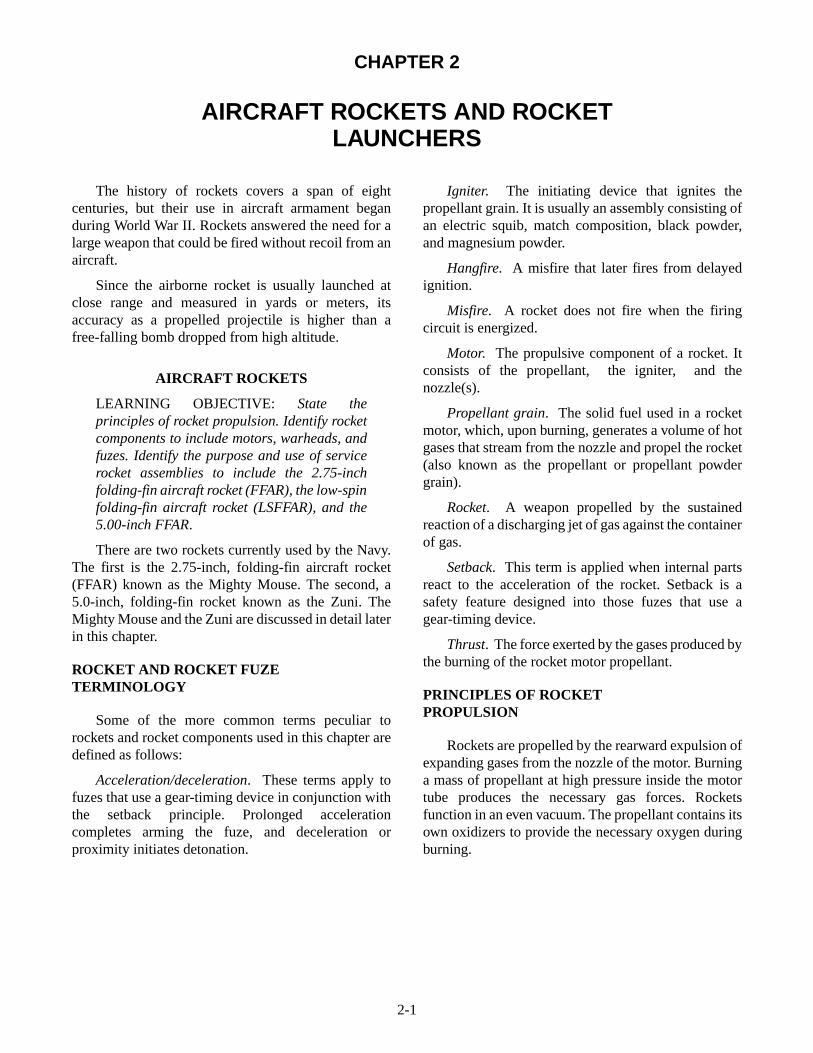
As you read this section, refer to figure 2-1. Tounderstand how a rocket operates, visualize a closedcontainer that contains a gas under pressure. Thepressure of the gas against all the interior surfaces isequal (view A). If the right end of the container isremoved (view B), the pressure against the left end willcause the container to move to the left.
In the rocket motor, gases produced by the burningpropellant are confined to permit a buildup of pressureto sustain a driving force. A Venturi-type nozzle (viewC) restricts the size of the opening. The Venturi-typenozzle decreases the turbulence of escaping gases andincreases the thrust. In this design, gas pressure insidethe container provides about 70 percent of the force,and the escaping gases provide about 30 percent of theforce necessary to move the container forward.
ROCKET COMPONENTS
A complete round of service rocket ammunitionconsists of three major components—the motor, thewarhead, and a fuze. A general description of thesecomponents is given in the following paragraphs.
Motors
The rocket motor consists of components thatpropel and stabilize the rocket in flight. Not all rocketmotors are identical, but they do have certain commoncomponents. These components are the motor tube,propellant, inhibitors, stabilizing rod, igniter, andnozzle and fin assembly. The rocket motors discussedin the following paragraphs are for the 2.75-inch Mk 66Mods 2 and 4, and 5.0-inch Mk 71 Mod 0 and 1.
MOTOR TUBE.—The motor tube supports theother components of the rocket. Presently, all motortubes are aluminum, threaded internally at the front endfor warhead installation, and grooved or threadedinternally at the aft end for nozzle and fin assemblyinstallation.
The Mk 66 Mods rocket motor tube is an integralbulkhead type of motor tube and is impact-extrudedfrom aluminum stock. The forward end contains thehead closure and threaded portion for attachment of thewarhead. The integral bulkhead closure does notrupture when accidentally fired without a warhead andbecomes propulsive when ignited. The center portion ofthe motor tube contains the propellant. The nozzle andfin assembly attaches to the aft end by a lock wire in agrove inside the tube.
The Mk 71 Mods rocket motor tube is basically analuminum tube with an integral bulkhead closure. Theforward end contains the head closure, igniter contactband, igniter lead, RAD HAZ barrier, and a threadedportion for attachment of the warhead. The centersection is the combustion chamber and contains theigniter, propellant grain, stabilizing rod, and associatedhardware. The aft end of the motor tube is threadedinternally to accept the nozzle and fin assembly.
PROPELLANTS.—The propellant graincontained in the Navy's 2.75-inch and the 5.0-inchrocket motors is an internal burning, star perforation,double-base solid propellant. The star perforation isdesigned to produce a nearly constant thrust level.
The Mk 66 rocket motor has the star pointsmachined off (conned) to reduce erosive burning.
INHIBITORS.—Inhibitors restrict or controlburning on the propellant surface. In the 2.75-inch andthe 5.0-inch motors, the propellant grains are inhibitedat the forward and aft ends, as well as the entire outersurface. The forward and aft end inhibitors are moldedplastic (ethyl cellulose) components bonded to thepropellant ends. The outer surface inhibitor is spirally
2-2
Figure 2-1.—Principles of rocket propulsion.
wrapped ethyl cellulose tape bonded to the propellantsurface.
Inhibitors cause the propellant grain to burn fromthe center outward and from forward to aft uniformly. Ifinhibitors weren't used, the burning surface of thepropellant grain would increase, and result in anincreased burning rate. This could cause the motor tubeto explode from excessive pressure. If a motor isaccidentally dropped and the propellant grain iscracked, the crack in the grain increases the burningsurface and an identical hazard exists.
STABILIZING ROD.—The stabilizing rod,located in the perforation of the motor propellant grain,is salt coated to prevent unstable burning of thepropellant. It also reduces flash and after burning in therocket motor, which could contribute to compressorstall and flameout of the aircraft jet engines. When thepropellant ignites, the stabilizing rod ensures that thegrain ignites simultaneously forward and aft.
IGNITER.—The igniter heats the propellant grainto ignition temperature. The igniter used in the2.75-inch motor is a disc-shaped metal container thatcontains a black powder and magnesium charge, asquib, and electrical lead wires. It is located at theforward end of the motor. The igniter used in the
5.0-inch motor is a disc-shaped metal container thatcontains a powder or pellets charge, two squibs, andelectrical lead wires. It is located at the forward end ofthe motor. A contact disc or a contact band transmits thefiring impulses to the motor igniter.
The 2.75-inch motor has electrical leads that extendfrom the squib through the wall of the igniter. They arerouted through the propellant perforation to the nozzlefin assembly. One of the wires is connected to thenozzle plate (ground), and the other passes througheither one of the nozzles or the fin-actuating piston tothe contact disc on the fin retainer. In the Mk 66 Mod 2,both lead wires are connected directly to the HEROfilter wires, which extend out of the forward end of thestabilizing rod. When the rocket is placed in thelauncher, the contact disc is automatically in contactwith an electrical terminal that transmits the firingimpulse to the rocket.
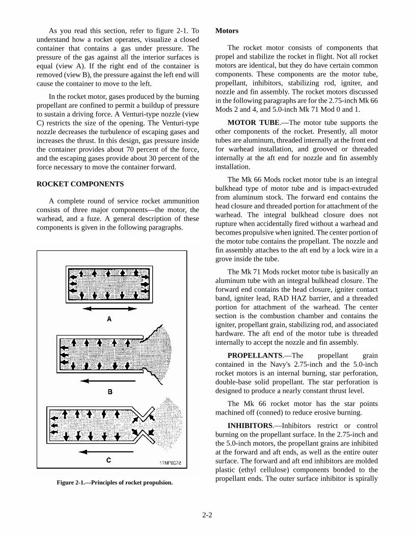
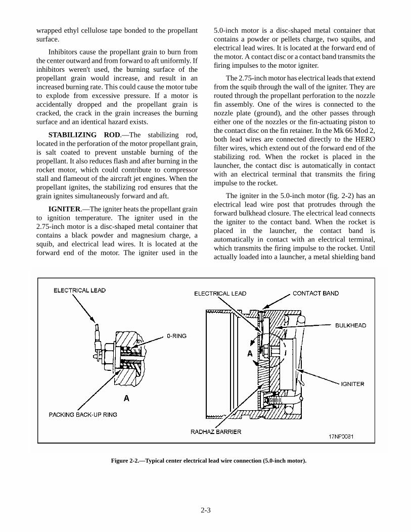
The igniter in the 5.0-inch motor (fig. 2-2) has anelectrical lead wire post that protrudes through theforward bulkhead closure. The electrical lead connectsthe igniter to the contact band. When the rocket isplaced in the launcher, the contact band isautomatically in contact with an electrical terminal,which transmits the firing impulse to the rocket. Untilactually loaded into a launcher, a metal shielding band
2-3
Figure 2-2.—Typical center electrical lead wire connection (5.0-inch motor).
(fig. 2-3) is always in place over the ignition contactband.
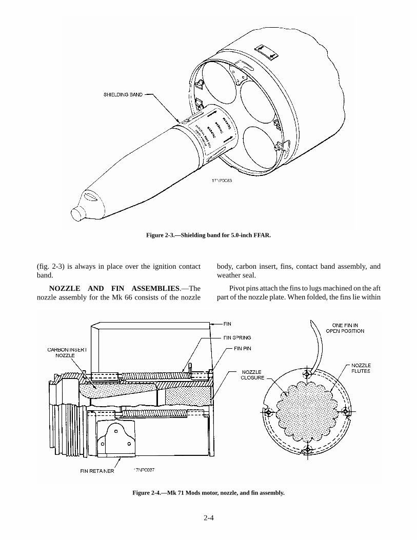
NOZZLE AND FIN ASSEMBLIES.—Thenozzle assembly for the Mk 66 consists of the nozzle
body, carbon insert, fins, contact band assembly, andweather seal.
Pivot pins attach the fins to lugs machined on the aftpart of the nozzle plate. When folded, the fins lie within
2-4
Figure 2-3.—Shielding band for 5.0-inch FFAR.
Figure 2-4.—Mk 71 Mods motor, nozzle, and fin assembly.
the 2.75-inch diameter of the rocket. The fins arenotched at the tips to allow attachment of a fin retainer.
The fin-actuating mechanism is a steel cylinder anda piston with a crosshead attached to its aft end. Whenthe rocket is fired, gas pressure from the motor operatesthe piston, cylinder, and crosshead. The crosshead ispushed against the heels of the fins, causing the fins torotate on the fin pivot pins to the open position after therocket leaves the launcher. After the fins have opened tothe final flight position, the crosshead prevents the finsfrom closing.
There are four nozzle inserts and the detent groovein the aft end of the nozzle plate. They hold the rocket inposition after it is loaded in the launcher.
The Mk 71 Mods motor has a modified igniter anda modified nozzle and fin assembly. The nozzle and finassembly (fig. 2-4) contains four, spring-loaded,wraparound fins inside the motor diameter. The steelnozzle expansion cone has flutes that cause the rocketto spin during free flight. This permits the rocket to belaunched from high-speed aircraft, helicopters, andlow-speed aircraft.
The Mk 71 Mods spring-loaded fins (fig. 2-5)deploy after emerging from the rocket launcher tube.They lock in place (open) by sliding into a locking slotin the flange at the aft end of the fin nozzle assembly.When not actually installed in the launcher, the fins areheld in the closed position by a fin retainer band, whichmust be removed when the rocket is installed into thelauncher tube. The fin retainer band is notinterchangeable with the shielding band.
REVIEW NUMBER 1
Q1. List the two rockets currently used by theNavy.
Q2. If a rocket does not fire when the firing circuitis energized, it is known as a _____________.
Q3. What is meant by the rockets thrust?
Q4. In rocket propulsion, the Venturi nozzledecreases turbulence of escaping gases andincreases thrust. Gas pressure inside thecontainer provides about _______, and theescaping gases provide about __________ tomove the container forward.
Q5. List the three components of a rocket.
Q6. List the components of rocket motors.
Q7. What is the purpose of the inhibitor?
Q8. What rocket component is salt coated toprevent unstable burning of the rocketpropellant?
Q9. When should you remove the fin retainer bandon a Mk 71 rocket motor?
Warheads
Different tactical requirements demand differenttypes of rocket warheads be used with airborne rockets.
2-5
Figure 2-5.—Mk 71 Mods motor, nozzle, and fin assembly.
Warheads are classified as either 2.75 inch or 5.0 inchwarheads. They may be further classified as highexplosive, flechette, smoke, flare, or practice.Warheads for 2.75-inch rockets are normally receivedwith the fuzes installed.
There are many different warheads, fuzes, andmotor combinations available. Therefore, the followingdiscussion is general. For specific componentinformation, you should refer to Aircraft RocketSystems 2.75-inch and 5.0-inch NAVAIR 11-75A-92.
High-explosive warheads contain high-explosivematerial (generally comp-B) surrounded by a metalcase. An internally threaded nose fuze cavity permitsthe installation of a nose fuze or an inert nose plug,depending on tactical requirements. Some warheadconfigurations require the use of a base fuze. Base fuzesare installed at the factory and should never beremoved. High-explosive warheads are painted olivedrab and may have a narrow yellow band around thenose.
There are several types of high-explosivewarheads, and each is designed for a specific type oftarget.
HE-FRAG WARHEADS.—High-explosive frag-mentation (HE-FRAG) warheads (fig. 2-6) are usedagainst personnel and light material targets, such astrucks and parked aircraft. Upon detonation, a largequantity of metal fragments accelerates to a high
velocity. This action damages the target. The types ofHE-FRAG warheads currently in use are listed in table2-1.
REVIEW NUMBER 1 ANSWERS
A1. The two rockets currently used by the Navyare the 2.75-inch Mighty Mouse and the5.0-inch Zuni.
A2. If a rocket does not fire when the firing circuitis energized, it is known as a misfire.
A3. Thrust is the force exerted by the gasesproduced by the burning of the rocket motorpropellant.
A4. In rocket propulsion, the Venturi nozzledecreases turbulence of escaping gases andincreases thrust. Gas pressure inside thecontainer provides about 70% of the force,and the escaping gases provide about 30% ofthe force to move the container forward.
A5. The three components of a rocket are themotor, warhead, and fuze.
A6. The components of rocket motors include themotor tube, propellant, inhibitors, stabilizingrod, igniter, and nozzle and fin assembly.
A7. The inhibitor restricts or controls burning onthe propellant.
2-6
Figure 2-6.—High-explosive fragmentation (HE-FRAG) warheads.
A8. The stabilizing rod is salt coated to preventunstable burning of the rocket propellant.
A9. You should remove the fin retainer band onthe Mk 71 rocket motor when the rocket isinstalled into the launcher tube.
AT/APERS WARHEAD.—The high-explosiveantitank/antipersonnel (AT/APERS) warhead (fig. 2-7)combines the effectiveness of the HE-FRAG and HEATwarheads. The explosive shaped-charge in the AT/APERS warhead detonates at the aft end, producing thejet from the cone at the forward end. The booster in theaft end detonates the warhead by transmitting anexplosive impulse along a length of detonating cord. Itconnects the booster charge to the initiating charge,which is next to the nose fuze. The combination of an
instantaneous-acting nose fuze and rapid-burningdetonating cord permits detonation of the explosiveload in time for the shaped-charge to produce itsexplosive jet before being disintegrated upon targetimpact. The only AT/APERS warhead currently in useis the Mk 32 Mod 0.
GP WARHEAD.—The high-explosive, general-purpose (GP) warhead (fig. 2-8) is a compromisebetween the armor-piercing and the fragmentationdesigns. The walls and nose section are not as strong asthose of an armor-piercing warhead, yet they arestronger than those of a fragmentation warhead. Theexplosive charge is greater than that in the armor-piercing warhead, but less than that in the frag-mentation warhead.
2-7
TYPE 2.75-INCH 5.0-INCH
HE-FRAG
AT/APERS
GP
FLECHETTE
SMOKE
FLARE
M151
----------
----------
WDU-4A/A
M156
Mk 67 Mod 0
M257
M278 IR
Mk 63 Mod 0
Mk 32 Mod 0
Mk 24 Mod 0
-----------
Mk 34 Mods 0 and 1
Mk 33 Mod 1
Table 2-1.—Service Warheads
Figure 2-7.—Mk 32 Mod 0 AT/APERS warhead.
Figure 2-8.—Mk 24 Mod 0 high-explosive, general-purpose (GP) warhead.
The GP warhead is used against a variety of targets.Maximum penetration is obtained by using a solid noseplug and the delayed-action base fuze. Its maximumblast effect is obtained by using an instantaneous-acting
nose fuze. The only GP warhead currently in use is theMk 24 Mod 0.
FLECHETTE WARHEADS.—Flechette war-heads (fig. 2-9) are used against personnel and light
2-8
Figure 2-9.—WDU-4A/A flechette warhead.
Figure 2-10.—Smoke warheads.
armored targets. These warheads contain a largenumber of small arrow-shaped projectiles. A smallexplosive charge in the base fuze of the warheaddispenses the flechettes through the nose of thewarhead after rocket motor burnout. Target damage iscaused by impact of the high-velocity flechettes.
SMOKE WARHEADS.—Smoke warheads (fig.2-10) are used to produce a volume of heavy smoke fortarget marking. The warhead contains a burster tube ofexplosives, usually comp-B, which bursts the walls ofthe warhead, dispersing the smoke. These warheads aredesignated SMOKE, followed by the abbreviation forthe smoke producing agent it contains. For example,WP for white phosphorus, or PWP for plasticized whitephosphorus. The types of smoke warheads currently inuse are listed in table 2-1.
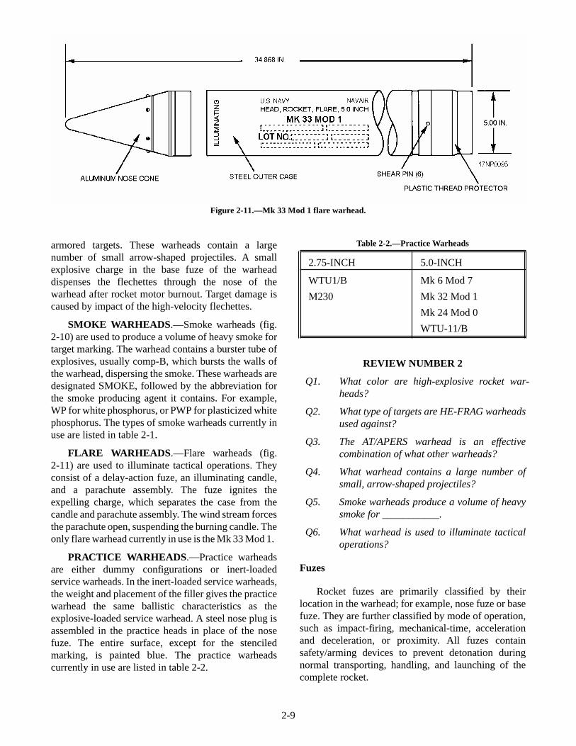
FLARE WARHEADS.—Flare warheads (fig.2-11) are used to illuminate tactical operations. Theyconsist of a delay-action fuze, an illuminating candle,and a parachute assembly. The fuze ignites theexpelling charge, which separates the case from thecandle and parachute assembly. The wind stream forcesthe parachute open, suspending the burning candle. Theonly flare warhead currently in use is the Mk 33 Mod 1.
PRACTICE WARHEADS.—Practice warheadsare either dummy configurations or inert-loadedservice warheads. In the inert-loaded service warheads,the weight and placement of the filler gives the practicewarhead the same ballistic characteristics as theexplosive-loaded service warhead. A steel nose plug isassembled in the practice heads in place of the nosefuze. The entire surface, except for the stenciledmarking, is painted blue. The practice warheadscurrently in use are listed in table 2-2.
Table 2-2.—Practice Warheads
2.75-INCH 5.0-INCH
WTU1/B
M230
Mk 6 Mod 7
Mk 32 Mod 1
Mk 24 Mod 0
WTU-11/B
REVIEW NUMBER 2
Q1. What color are high-explosive rocket war-heads?
Q2. What type of targets are HE-FRAG warheadsused against?
Q3. The AT/APERS warhead is an effectivecombination of what other warheads?
Q4. What warhead contains a large number ofsmall, arrow-shaped projectiles?
Q5. Smoke warheads produce a volume of heavysmoke for ___________.
Q6. What warhead is used to illuminate tacticaloperations?
Fuzes
Rocket fuzes are primarily classified by theirlocation in the warhead; for example, nose fuze or basefuze. They are further classified by mode of operation,such as impact-firing, mechanical-time, accelerationand deceleration, or proximity. All fuzes containsafety/arming devices to prevent detonation duringnormal transporting, handling, and launching of thecomplete rocket.
2-9
Figure 2-11.—Mk 33 Mod 1 flare warhead.
A representative fuze from each class is discussedin the following paragraphs. The fuzes currently in useand their primary application are listed in table 2-3. Formore detailed information on fuzes, refer to AircraftRocket Systems 2.75-inch and 5.0-inch NAV-AIR 11-75A-92.
REVIEW NUMBER 2 ANSWERS
A1. High-explosive rocket warheads are paintedolive drab and may have a narrow yellowband around the nose.
A2. HE-FRAG warheads are used againstpersonnel and light material targets, such astrucks and parked aircraft.
A3. The AT/APERS warhead is an effectivecombination of the HE-FRAG and HEATwarheads.
A4. The flechette warhead contains a largenumber of small, arrow-shaped projectiles.
A5. Smoke warheads produce a volume of heavysmoke for target marking.
A6. The flare warhead is used to illuminatetactical operations.
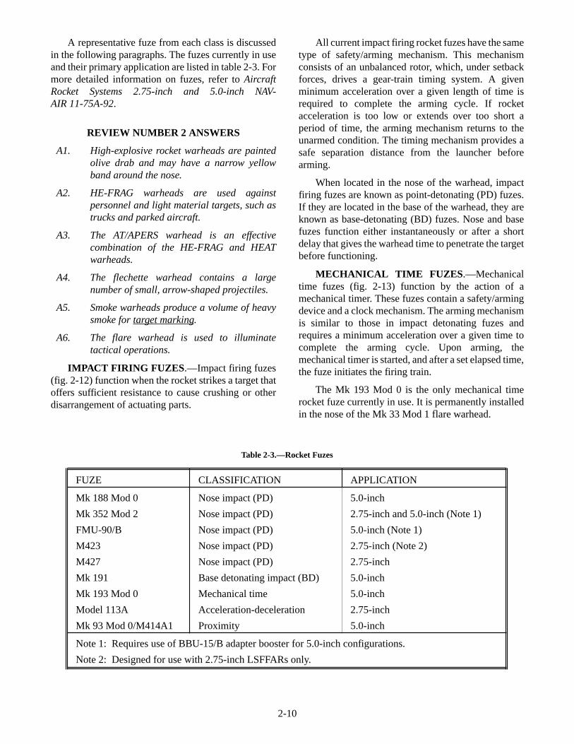
IMPACT FIRING FUZES.—Impact firing fuzes(fig. 2-12) function when the rocket strikes a target thatoffers sufficient resistance to cause crushing or otherdisarrangement of actuating parts.
All current impact firing rocket fuzes have the sametype of safety/arming mechanism. This mechanismconsists of an unbalanced rotor, which, under setbackforces, drives a gear-train timing system. A givenminimum acceleration over a given length of time isrequired to complete the arming cycle. If rocketacceleration is too low or extends over too short aperiod of time, the arming mechanism returns to theunarmed condition. The timing mechanism provides asafe separation distance from the launcher beforearming.
When located in the nose of the warhead, impactfiring fuzes are known as point-detonating (PD) fuzes.If they are located in the base of the warhead, they areknown as base-detonating (BD) fuzes. Nose and basefuzes function either instantaneously or after a shortdelay that gives the warhead time to penetrate the targetbefore functioning.
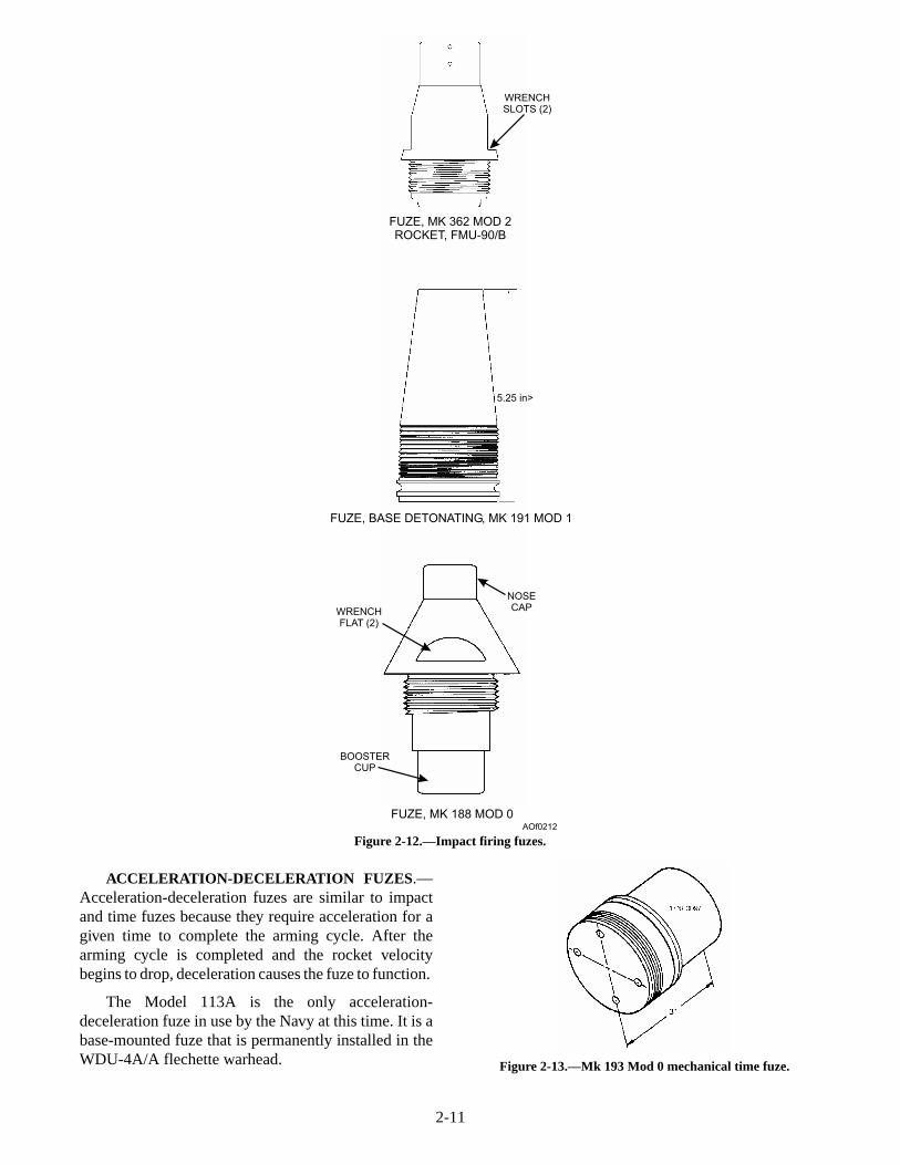
MECHANICAL TIME FUZES.—Mechanicaltime fuzes (fig. 2-13) function by the action of amechanical timer. These fuzes contain a safety/armingdevice and a clock mechanism. The arming mechanismis similar to those in impact detonating fuzes andrequires a minimum acceleration over a given time tocomplete the arming cycle. Upon arming, themechanical timer is started, and after a set elapsed time,the fuze initiates the firing train.
The Mk 193 Mod 0 is the only mechanical timerocket fuze currently in use. It is permanently installedin the nose of the Mk 33 Mod 1 flare warhead.
2-10
FUZE CLASSIFICATION APPLICATION
Mk 188 Mod 0
Mk 352 Mod 2
FMU-90/B
M423
M427
Mk 191
Mk 193 Mod 0
Model 113A
Mk 93 Mod 0/M414A1
Nose impact (PD)
Nose impact (PD)
Nose impact (PD)
Nose impact (PD)
Nose impact (PD)
Base detonating impact (BD)
Mechanical time
Acceleration-deceleration
Proximity
5.0-inch
2.75-inch and 5.0-inch (Note 1)
5.0-inch (Note 1)
2.75-inch (Note 2)
2.75-inch
5.0-inch
5.0-inch
2.75-inch
5.0-inch
Note 1: Requires use of BBU-15/B adapter booster for 5.0-inch configurations.
Note 2: Designed for use with 2.75-inch LSFFARs only.
Table 2-3.—Rocket Fuzes
ACCELERATION-DECELERATION FUZES.—Acceleration-deceleration fuzes are similar to impactand time fuzes because they require acceleration for agiven time to complete the arming cycle. After thearming cycle is completed and the rocket velocitybegins to drop, deceleration causes the fuze to function.
The Model 113A is the only acceleration-deceleration fuze in use by the Navy at this time. It is abase-mounted fuze that is permanently installed in theWDU-4A/A flechette warhead.
2-11
WRENCHSLOTS (2)
FUZE, MK 362 MOD 2ROCKET, FMU-90/B
5.25 in>
FUZE, BASE DETONATING, MK 191 MOD 1
NOSECAPWRENCH
FLAT (2)
BOOSTERCUP
FUZE, MK 188 MOD 0AOf0212
Figure 2-12.—Impact firing fuzes.
Figure 2-13.—Mk 193 Mod 0 mechanical time fuze.
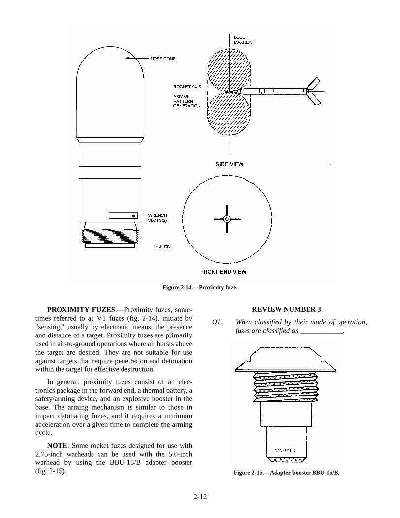
PROXIMITY FUZES.—Proximity fuzes, some-times referred to as VT fuzes (fig. 2-14), initiate by"sensing," usually by electronic means, the presenceand distance of a target. Proximity fuzes are primarilyused in air-to-ground operations where air bursts abovethe target are desired. They are not suitable for useagainst targets that require penetration and detonationwithin the target for effective destruction.
In general, proximity fuzes consist of an elec-tronics package in the forward end, a thermal battery, asafety/arming device, and an explosive booster in thebase. The arming mechanism is similar to those inimpact detonating fuzes, and it requires a minimumacceleration over a given time to complete the armingcycle.
NOTE: Some rocket fuzes designed for use with2.75-inch warheads can be used with the 5.0-inchwarhead by using the BBU-15/B adapter booster(fig. 2-15).
REVIEW NUMBER 3
Q1. When classified by their mode of operation,fuzes are classified as ____________.
2-12
Figure 2-14.—Proximity fuze.
Figure 2-15.—Adapter booster BBU-15/B.
Q2. At what point does the impact-firing fuzefunction?
Q3. List the two types of impact firing fuzes.
Q4. At what point does the mechanical time fuzeinitiate the firing train?
Q5. In acceleration-deceleration fuzes, whatforce causes the fuze to function?
Q6. Name the fuze that senses, usually byelectronic means, the presence and distanceof a target.
SERVICE ROCKET ASSEMBLIES
Airborne rockets, consisting of fuzes, warheads,and motors, are combined and assembled in variousconfigurations to meet specific tactical requirements.For example, a rocket assembly that consists of afragmentation warhead armed with a proximity fuze isentirely unsuitable for use against an armored tank orbunker. Likewise, the GP warhead fuzed only with theMk 191 base fuze is relatively ineffective againstpersonnel or unarmored targets. With each specific typeof target, the right combination of warhead, fuze, andmotor is assembled from the wide variety ofcomponents available.
2.75-Inch FFAR and LSFFAR
The 2.75-inch airborne rocket is an effectiveair-to-ground weapon against most targets. The FFARis an air-to-air weapon. Fired in large numbers toproduce a shotgun pattern, FFARs are carried andlaunched from 7- or 19-round launcher packages.These packages are described later in this chapter.
The LSFFAR is accurately and safely launchedfrom low-speed aircraft and helicopters. Because oftheir spin feature, they cannot be ripple fired. LSFFARsare fired singly from 7- or 19-round launchers that havesingle-fire capability.
The 2.75-inch rockets are received through thesupply system in three configurations as follows:
1. Complete rounds in 7- or 19-tube launchers, orin wooden boxes
2. Rocket motors in 7-tube launchers, and thefuze-warhead combination in separateshipping containers
3. Separate components in authorized shippingcontainers
Squadron ordnancemen based ashore order andmay assemble components for current operations.Aboard ship, weapons department ordnancemenassemble the components according to the ship's air andload plan. They deliver these assemblies to squadronordnancemen for loading onto aircraft.
For detailed information, such as authorizedassemblies, safety precautions, and restrictions, youshould refer to Aircraft Rocket Systems 2.75-inch and5.0-inch NAVAIR 11-75A-92. You can find additionalinformation in specific aircraft loading and tacticalmanuals.
5.0-Inch FFAR
Like the 2.75-inch rocket, the 5.0-inch FFAR canbe assembled in various warhead and fuzecombinations. The Mk 71 motor gives the additionaladvantage of one motor for all launch-speedapplications.
The 5.0-inch rocket is carried and launched frommultiple-round launchers. Because of their large sizeand weight, the number of rounds per launcher isreduced to four. The 5.0-inch rockets are receivedthrough the supply system in the following twoconfigurations:
1. Rocket motors in a 4-round launcher and fuzesand warheads in separate shipping containers
NOTE: The Mk 191, Mk 193, and Model113A fuzes are permanently installed in thewarheads.
2. Separate components in separate shippingcontainers
REVIEW NUMBER 4
Q1. What is the usual configuration of the2.75-inch airborne rocket?
Q2. Aboard ship, who assembles rocket com-ponents for current operations?
REVIEW NUMBER 3 ANSWERS
A1. When classified by their mode of operation,fuzes are classified as impact firing,mechanical time, acceleration-deceleration,or proximity.
A2. Impact-firing fuzes function when the rocketstrikes the target that offers enough resistanceto cause actuation of the parts.
2-13
A3. The two types of impact firing fuzes are thepoint detonating and base detonating types.
A4. Upon arming, the mechanical timer starts,and after a set time, the mechanical time fuzeinitiates the firing train.
A5. In acceleration-deceleration fuzes,deceleration causes the fuze to function.
A6. Proximity fuzes sense, usually by electronicmeans, the presence and distance of a target.
AIRCRAFT ROCKET LAUNCHERS
LEARNING OBJECTIVE: Recognize theshipping configuration for aircraft rocketlaunchers and identify common aircraft rocketlauncher components.
Aircraft rocket launchers (pods) carry and providea platform to fire rockets. Launcher design permitsmultiple loading and launching of 2.75-inch and5.0-inch rockets. Rocket pods let rocket motors (and, insome cases, completely assembled rounds) stay in thesame container from their manufacture, throughstowage, to their final firing.
Aircraft rocket launchers are classified as either2.75-inch or 5.0-inch. They may be further classified aseither reusable or nonreusable. Launcher tubes that areconstructed of metal are considered reusable and are
usually returned for reloading. Under certainconditions, they may be jettisoned at the pilot'sdiscretion.
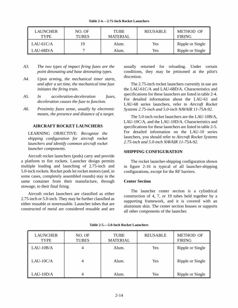
The 2.75-inch rocket launchers currently in use arethe LAU-61C/A and LAU-68D/A. Characteristics andspecifications for these launchers are listed in table 2-4.For detailed information about the LAU-61 andLAU-68 series launchers, refer to Aircraft RocketSystems 2.75-inch and 5.0-inch NAVAIR 11-75A-92.
The 5.0-inch rocket launchers are the LAU-10B/A,LAU-10C/A, and the LAU-10D/A. Characteristics andspecifications for these launchers are listed in table 2-5.For detailed information on the LAU-10 serieslaunchers, you should refer to Aircraft Rocket Systems2.75-inch and 5.0-inch NAVAIR 11-75A-92.
SHIPPING CONFIGURATION
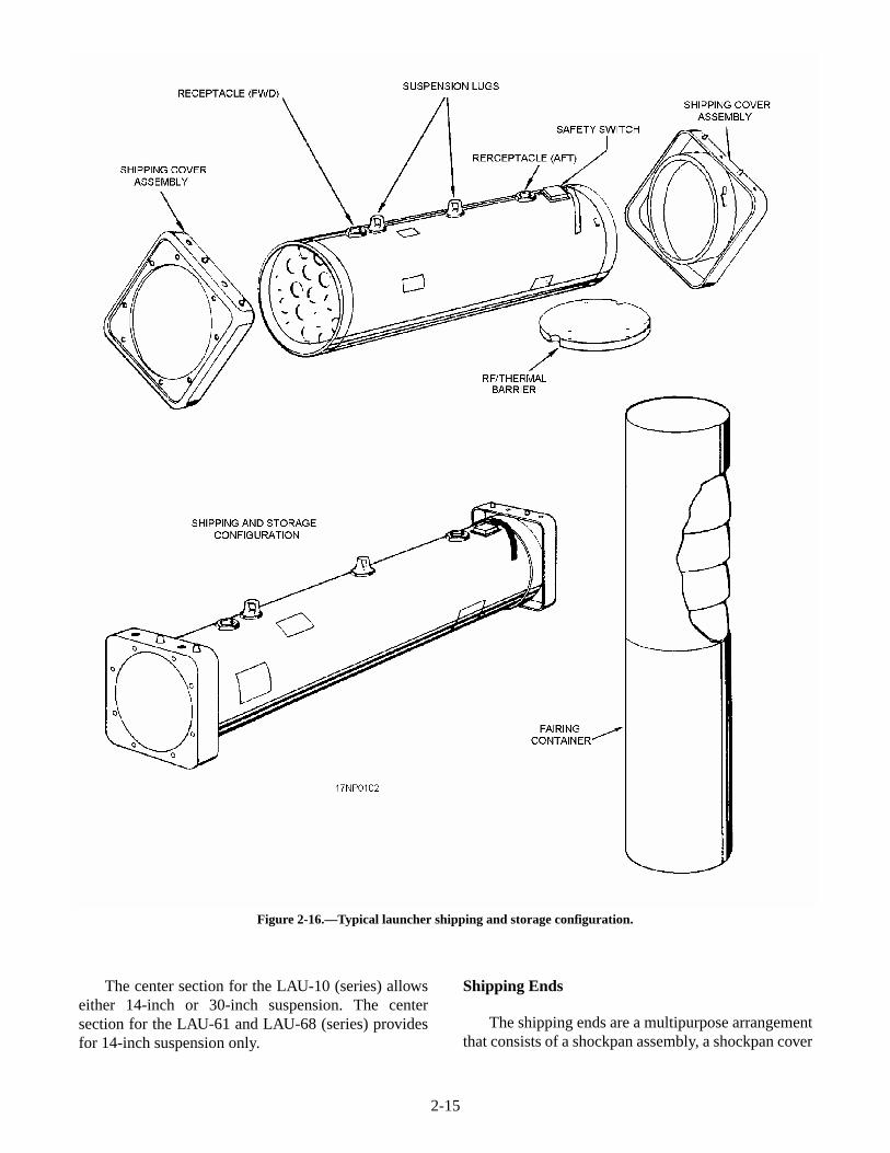
The rocket launcher-shipping configuration shownin figure 2-16 is typical of all launcher-shippingconfigurations, except for the RF barriers.
Center Section
The launcher center section is a cylindricalconstruction of 4, 7, or 19 tubes held together by asupporting framework, and it is covered with analuminum skin. The center section houses or supportsall other components of the launcher.
2-14
LAUNCHERTYPE
NO. OFTUBES
TUBEMATERIAL
REUSABLE METHOD OFFIRING
LAU-61C/A
LAU-68D/A
19
7
Alum.
Alum.
Yes
Yes
Ripple or Single
Ripple or Single
Table 2-4.—2.75-Inch Rocket Launchers
LAUNCHERTYPE
NO. OFTUBES
TUBEMATERIAL
REUSABLE METHOD OFFIRING
LAU-10B/A
LAU-10C/A
LAU-10D/A
4
4
4
Alum.
Alum.
Alum.
Yes
Yes
Yes
Ripple or Single
Ripple or Single
Ripple or Single
Table 2-5.—5.0-Inch Rocket Launchers
The center section for the LAU-10 (series) allowseither 14-inch or 30-inch suspension. The centersection for the LAU-61 and LAU-68 (series) providesfor 14-inch suspension only.
Shipping Ends
The shipping ends are a multipurpose arrangementthat consists of a shockpan assembly, a shockpan cover
2-15
Figure 2-16.—Typical launcher shipping and storage configuration.
assembly, and/or locking ring assembly. An alternatehole and pin arrangement on the top and bottom isarranged so that the shockpans interlock when thelaunchers are stacked. The cover is equipped with arubber seal ring that, when compressed by the lockingring assembly, forms a watertight closure over the endof the launcher.
RF/Thermal Barriers
RF/Thermal barriers consist of a molded,expanded, polystyrene bead base with an aluminum foilcoating cemented to the outer surface. RF/Thermalbarriers are used on 2.75-inch pods to prevent the entryof electromagnetic radiation into the rocket ignitercircuit. Equally important is the barrier on the aft end ofthe pod. It prevents exposure of the igniter lead contact.The LAU-61 and LAU-68 use the aft barrier only. Thebarriers remain installed for flight and are removed byimpact or blast when the rocket is fired.
COMMON COMPONENTS
Rocket launcher packages have several com-ponents that are common to all or most launcherpackages. Any notable differences are pointed out inthe following discussion.
REVIEW NUMBER 4 ANSWERS
A1. The 2.75-inch airborne rocket is used as anair-to-ground weapon against most targets.
A2. Aboard ship, weapons department ordnance-men assemble rocket components accordingto ships and load plans, and deliver them tothe squadron ordnancemen who load themonto the aircraft.
Fairings
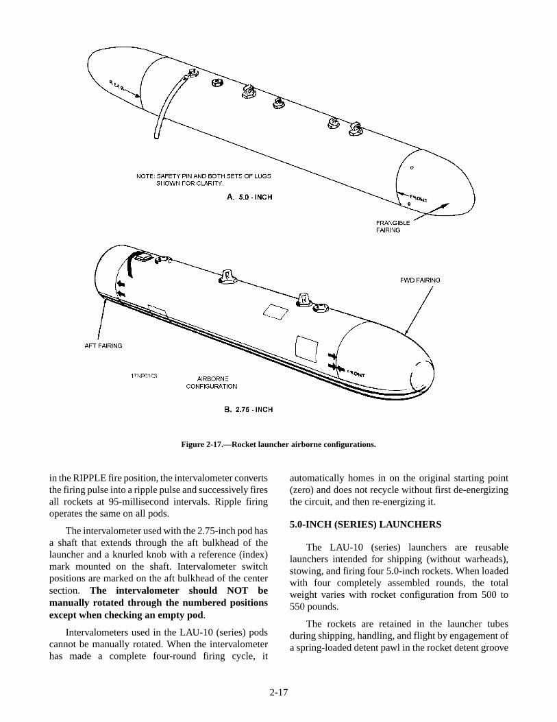
Frangible fairings (fig. 2-17) are made of animpregnated molded fiber designed with a waffle- orgrenade-type structure that shatters readily upon rocketimpact or from a blast. The fairings fit flush with theoutside surface of the center section and form anaerodynamically smooth joint. The forward fairingconsists of a one-piece molded section thatdisintegrates on rocket impact. The tail fairing for theLAU-10 (series) (fig. 2-17, view A) is molded in twosections (nose and base). The rocket blast shatters thenose portion. The base section remains on the launcherand acts as a choke or funnel to direct debris away fromthe aircraft. The tail fairings for the LAU-61 and
LAU-68 (series) are distinctively different inappearance (fig. 2-17, view B). They are made ofaluminum and are open on both ends. They function inthe same manner as the base section of the tail fairingfor the LAU-10 (series).
Fairings are not shipped with the rocket launcherpackages. They must be ordered separately and arereceived in sets packaged in cylindrical-shapedcardboard fairing containers (fig. 2-16).
Fairings are not used in all applications. You shouldreview the specific aircraft tactical manual for anyrestrictions in their use.
Breaker Switch
A breaker switch is used on all rocket launchers.The breaker switch is a safe-arm device that preventsloaded rockets from firing. It is usually located on thetop of the center section of the launcher between the aftend and the aft electrical receptacle.
With the detent pin installed in the breaker switch,the electrical system is grounded in the safe positionand the rockets won't fire. The detent pin has aREMOVE BEFORE FLIGHT red streamer attached.Pull the pin immediately before the aircraft takes offand install it immediately after the aircraft lands.
Install the detent pin in the breaker switch beforeloading the launcher with rocket motors. Keep detentpin installed, except during actual flight, until thelauncher is downloaded and/or verified as being empty.
Mode Selector Switch
The mode selector switch is used on all launchers.The switch is located in the aft bulkhead of thelauncher. The switch permits preflight selection ofeither ripple or single firing of the rockets bycontrolling the functioning of the pod intervalometer.
Intervalometer
The intervalometer for the LAU-10 (series) pods islocated in the forward bulkhead of the center sectionand in the aft bulkhead for the LAU-61 and LAU-68(series). Intervalometers, whether installed in 5.0-inchor 2.75-inch launchers, perform the same function.
If the mode selector switch is in the SINGLE fireposition, the intervalometer fires one rocket on eachfiring pulse. If the mode selector switch in the 19-shotpod is in the SINGLE fire position, the intervalometerfires the rockets in pairs. If the mode selector switch is
2-16
in the RIPPLE fire position, the intervalometer convertsthe firing pulse into a ripple pulse and successively firesall rockets at 95-millisecond intervals. Ripple firingoperates the same on all pods.
The intervalometer used with the 2.75-inch pod hasa shaft that extends through the aft bulkhead of thelauncher and a knurled knob with a reference (index)mark mounted on the shaft. Intervalometer switchpositions are marked on the aft bulkhead of the centersection. The intervalometer should NOT bemanually rotated through the numbered positionsexcept when checking an empty pod.
Intervalometers used in the LAU-10 (series) podscannot be manually rotated. When the intervalometerhas made a complete four-round firing cycle, it
automatically homes in on the original starting point(zero) and does not recycle without first de-energizingthe circuit, and then re-energizing it.
5.0-INCH (SERIES) LAUNCHERS
The LAU-10 (series) launchers are reusablelaunchers intended for shipping (without warheads),stowing, and firing four 5.0-inch rockets. When loadedwith four completely assembled rounds, the totalweight varies with rocket configuration from 500 to550 pounds.
The rockets are retained in the launcher tubesduring shipping, handling, and flight by engagement ofa spring-loaded detent pawl in the rocket detent groove
2-17
Figure 2-17.—Rocket launcher airborne configurations.
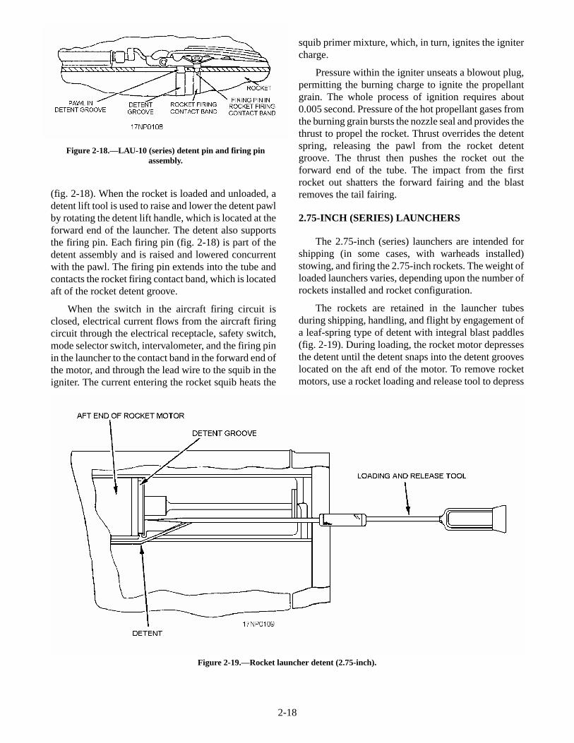
(fig. 2-18). When the rocket is loaded and unloaded, adetent lift tool is used to raise and lower the detent pawlby rotating the detent lift handle, which is located at theforward end of the launcher. The detent also supportsthe firing pin. Each firing pin (fig. 2-18) is part of thedetent assembly and is raised and lowered concurrentwith the pawl. The firing pin extends into the tube andcontacts the rocket firing contact band, which is locatedaft of the rocket detent groove.
When the switch in the aircraft firing circuit isclosed, electrical current flows from the aircraft firingcircuit through the electrical receptacle, safety switch,mode selector switch, intervalometer, and the firing pinin the launcher to the contact band in the forward end ofthe motor, and through the lead wire to the squib in theigniter. The current entering the rocket squib heats the
squib primer mixture, which, in turn, ignites the ignitercharge.
Pressure within the igniter unseats a blowout plug,permitting the burning charge to ignite the propellantgrain. The whole process of ignition requires about0.005 second. Pressure of the hot propellant gases fromthe burning grain bursts the nozzle seal and provides thethrust to propel the rocket. Thrust overrides the detentspring, releasing the pawl from the rocket detentgroove. The thrust then pushes the rocket out theforward end of the tube. The impact from the firstrocket out shatters the forward fairing and the blastremoves the tail fairing.
2.75-INCH (SERIES) LAUNCHERS
The 2.75-inch (series) launchers are intended forshipping (in some cases, with warheads installed)stowing, and firing the 2.75-inch rockets. The weight ofloaded launchers varies, depending upon the number ofrockets installed and rocket configuration.
The rockets are retained in the launcher tubesduring shipping, handling, and flight by engagement ofa leaf-spring type of detent with integral blast paddles(fig. 2-19). During loading, the rocket motor depressesthe detent until the detent snaps into the detent grooveslocated on the aft end of the motor. To remove rocketmotors, use a rocket loading and release tool to depress
2-18
Figure 2-18.—LAU-10 (series) detent pin and firing pinassembly.
Figure 2-19.—Rocket launcher detent (2.75-inch).
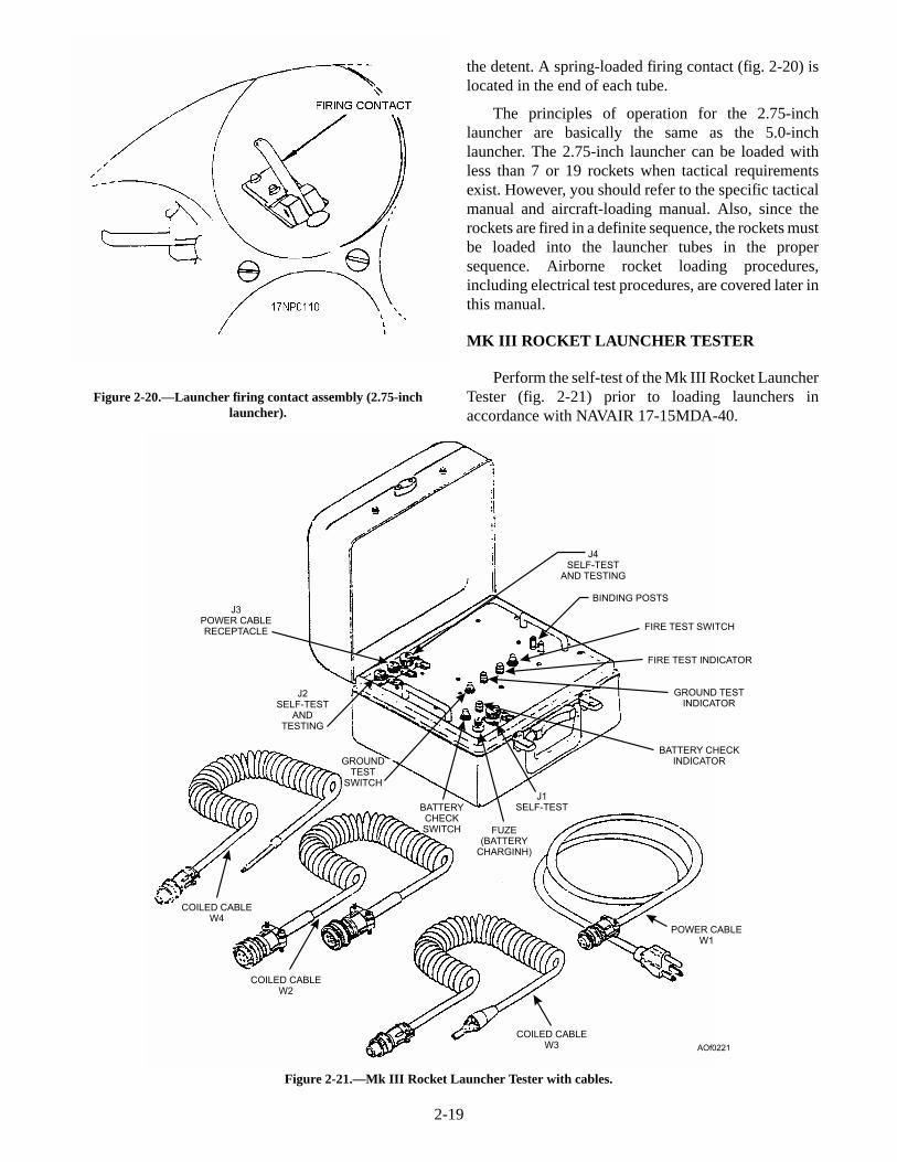
the detent. A spring-loaded firing contact (fig. 2-20) islocated in the end of each tube.
The principles of operation for the 2.75-inchlauncher are basically the same as the 5.0-inchlauncher. The 2.75-inch launcher can be loaded withless than 7 or 19 rockets when tactical requirementsexist. However, you should refer to the specific tacticalmanual and aircraft-loading manual. Also, since therockets are fired in a definite sequence, the rockets mustbe loaded into the launcher tubes in the propersequence. Airborne rocket loading procedures,including electrical test procedures, are covered later inthis manual.
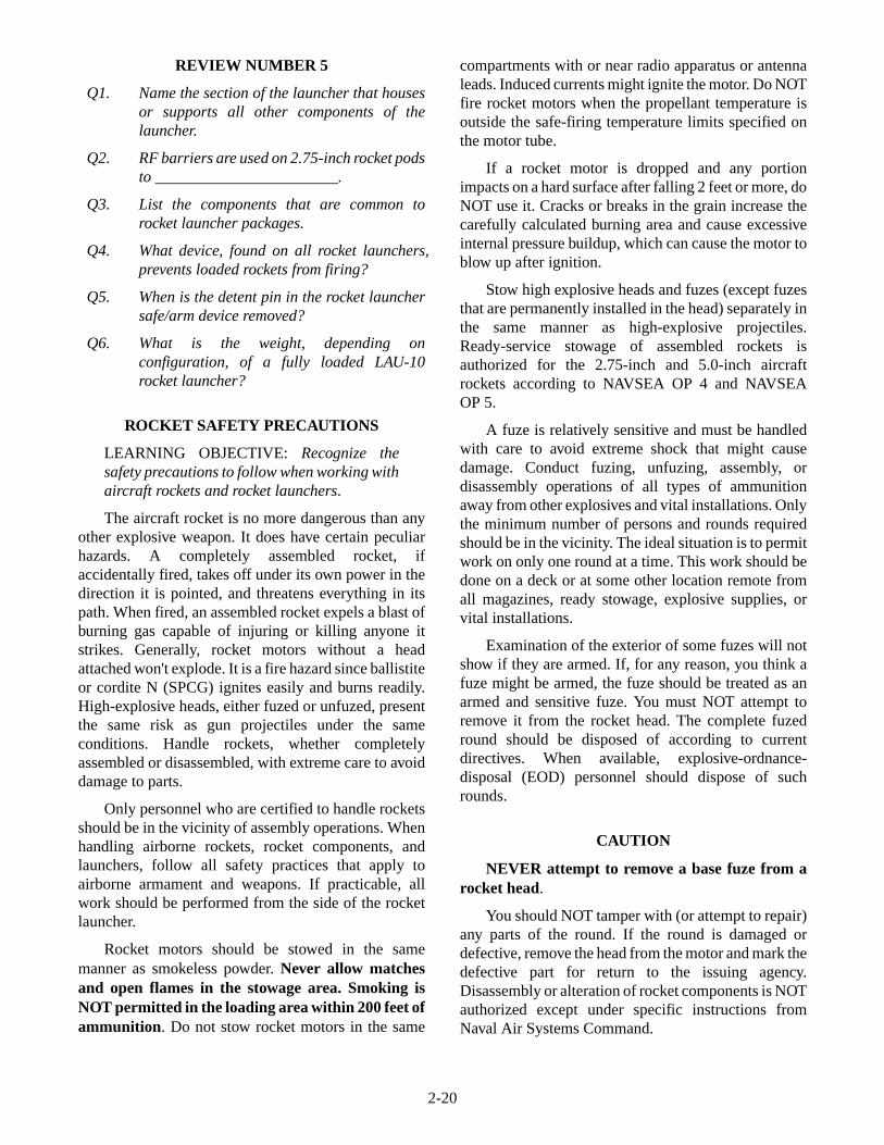
MK III ROCKET LAUNCHER TESTER
Perform the self-test of the Mk III Rocket LauncherTester (fig. 2-21) prior to loading launchers inaccordance with NAVAIR 17-15MDA-40.
2-19
Figure 2-20.—Launcher firing contact assembly (2.75-inchlauncher).
J3POWER CABLERECEPTACLE
J2SELF-TEST
ANDTESTING
J4SELF-TEST
AND TESTING
BINDING POSTS
FIRE TEST SWITCH
FIRE TEST INDICATOR
GROUND TESTINDICATOR
BATTERY CHECKINDICATOR
J1SELF-TEST
FUZE(BATTERY
CHARGINH)
GROUNDTEST
SWITCH
BATTERYCHECKSWITCH
POWER CABLEW1
COILED CABLEW3
COILED CABLEW2
COILED CABLEW4
AOf0221
Figure 2-21.—Mk III Rocket Launcher Tester with cables.
REVIEW NUMBER 5
Q1. Name the section of the launcher that housesor supports all other components of thelauncher.
Q2. RF barriers are used on 2.75-inch rocket podsto _______________________.
Q3. List the components that are common torocket launcher packages.
Q4. What device, found on all rocket launchers,prevents loaded rockets from firing?
Q5. When is the detent pin in the rocket launchersafe/arm device removed?
Q6. What is the weight, depending onconfiguration, of a fully loaded LAU-10rocket launcher?
ROCKET SAFETY PRECAUTIONS
LEARNING OBJECTIVE: Recognize thesafety precautions to follow when working withaircraft rockets and rocket launchers.
The aircraft rocket is no more dangerous than anyother explosive weapon. It does have certain peculiarhazards. A completely assembled rocket, ifaccidentally fired, takes off under its own power in thedirection it is pointed, and threatens everything in itspath. When fired, an assembled rocket expels a blast ofburning gas capable of injuring or killing anyone itstrikes. Generally, rocket motors without a headattached won't explode. It is a fire hazard since ballistiteor cordite N (SPCG) ignites easily and burns readily.High-explosive heads, either fuzed or unfuzed, presentthe same risk as gun projectiles under the sameconditions. Handle rockets, whether completelyassembled or disassembled, with extreme care to avoiddamage to parts.
Only personnel who are certified to handle rocketsshould be in the vicinity of assembly operations. Whenhandling airborne rockets, rocket components, andlaunchers, follow all safety practices that apply toairborne armament and weapons. If practicable, allwork should be performed from the side of the rocketlauncher.
Rocket motors should be stowed in the samemanner as smokeless powder. Never allow matchesand open flames in the stowage area. Smoking isNOT permitted in the loading area within 200 feet ofammunition. Do not stow rocket motors in the same
compartments with or near radio apparatus or antennaleads. Induced currents might ignite the motor. Do NOTfire rocket motors when the propellant temperature isoutside the safe-firing temperature limits specified onthe motor tube.
If a rocket motor is dropped and any portionimpacts on a hard surface after falling 2 feet or more, doNOT use it. Cracks or breaks in the grain increase thecarefully calculated burning area and cause excessiveinternal pressure buildup, which can cause the motor toblow up after ignition.
Stow high explosive heads and fuzes (except fuzesthat are permanently installed in the head) separately inthe same manner as high-explosive projectiles.Ready-service stowage of assembled rockets isauthorized for the 2.75-inch and 5.0-inch aircraftrockets according to NAVSEA OP 4 and NAVSEAOP 5.
A fuze is relatively sensitive and must be handledwith care to avoid extreme shock that might causedamage. Conduct fuzing, unfuzing, assembly, ordisassembly operations of all types of ammunitionaway from other explosives and vital installations. Onlythe minimum number of persons and rounds requiredshould be in the vicinity. The ideal situation is to permitwork on only one round at a time. This work should bedone on a deck or at some other location remote fromall magazines, ready stowage, explosive supplies, orvital installations.
Examination of the exterior of some fuzes will notshow if they are armed. If, for any reason, you think afuze might be armed, the fuze should be treated as anarmed and sensitive fuze. You must NOT attempt toremove it from the rocket head. The complete fuzedround should be disposed of according to currentdirectives. When available, explosive-ordnance-disposal (EOD) personnel should dispose of suchrounds.
CAUTION
NEVER attempt to remove a base fuze from arocket head.
You should NOT tamper with (or attempt to repair)any parts of the round. If the round is damaged ordefective, remove the head from the motor and mark thedefective part for return to the issuing agency.Disassembly or alteration of rocket components is NOTauthorized except under specific instructions fromNaval Air Systems Command.
2-20
Fuzes and/or warheads dropped 5 feet or more ontoa hard surface and rockets that have been accidentallyreleased from aircraft launchers upon aircraft landingmust be disposed of according to current directives. If aloaded launcher is dropped, you should NOT use it untilthe launcher tubes, latching mechanisms, and rocketsare inspected for damage.
Rocket launchers should NOT be suspended from abomb rack that does not have independent ignition andjettisoning circuits. To prevent possible explosion, doNOT expose airborne rockets or loaded launchers to theexhaust from jet engine starter pods or gas turbinecompressors. A minimum distance, as indicated on theunit, must be maintained between the gas turbineexhaust path and rocket assemblies upon which theexhaust impinges. In the absence of specificinformation on the unit, a minimum distance of 10 feetmust be maintained.
Rockets should NOT be loaded or unloaded fromlaunchers while on the flight deck. RF barriers shouldremain in place on the launcher while on the flightdeck.
The detent pin must be in the breaker switch at alltimes. The only exceptions are when you are makingcertain electrical checks, or when the aircraft is readyfor flight. Do NOT, under any circumstances, performan electrical test with rockets in the launcher.
REVIEW NUMBER 6
Q1. If you are working around rockets or loadedpods, the preferred position is __________.
Q2. Smoking is not permitted within whatminimum range of rocket ammunition?
Q3. What is the maximum distance that a rocketmotor can be dropped and still be used as aserviceable motor?
Q4. What minimum distance must be maintainedbetween gas turbine exhaust paths androckets?
REVIEW NUMBER 5 ANSWERS
A1. The center section of the launcher that housesor supports all other components of thelauncher.
A2. RF barriers are used on 2.75-inch rocket podsto prevent entry of electromagnetic radiationinto the igniter circuit.
A3. The components that are common to rocketlauncher packages are as follows: fairings,breaker switch, mode selector switch, andintervalometer.
A4. The breaker switch, found on all rocketlaunchers, prevents loaded rockets fromfiring.
A5. The detent pin in the rocket launcher safe/armdevice is removed immediately before takeoff.
A6. The weight, depending on configuration, of afully loaded LAU-10 rocket launcher isapproximately 500 to 550 pounds.
REVIEW NUMBER 6 ANSWERS
A1. If you are working around rockets or loadedpods, the preferred position is at the sides ofthe rocket or pod. Never work in front orbehind them.
A2. Smoking is not permitted within 200 feet ofrocket ammunition.
A3. A rocket motor can be dropped 2 feet and stillbe used as a serviceable motor.
A4. A minimum of 10 feet must be maintainedbetween gas turbine exhaust paths androckets.
2-21
