air to water heat pumps installation, commissioning and
TRANSCRIPT

Multiple instructions: Consult the specific part
Read and understand the instructions before undertaking any work on the unit
RETA
IN F
OR F
UTUR
E RE
FERE
NCE
Incorporated in this document are the following:• Declaration of conformity• Technical manual
MTEC.5001.GB-A-1 Operation and maintenance manual LZT series English Rev. A 11-2020 Lochinvar Original Instructions
AMICUS HT RANGE INSTALLATION, COMMISSIONING AND SERVICE MANUAL
HIGH EFFICIENCY AIR TO WATER HEAT PUMPS WITH E.V.I. COMPRESSORS
LZT P2U/P2S SERIESMODELS 252 - 1202
Rev. A 11-20202
INDEX
1. INTRODUCTION ................................................................................................................................................................................... 4 1.1 Preliminary information .................................................................................................................................................... 4 1.2 Aim and content of the manual ....................................................................................................................................... 4 1.3 How to store this manual ................................................................................................................................................. 4 1.4 Manual updates ............................................................................................................................................................... 4 1.5 How to use this manual ................................................................................................................................................... 4 1.6 Potential risks .................................................................................................................................................................. 5 1.7 General description of symbols used ............................................................................................................................... 6 1.8 Safety symbols used ........................................................................................................................................................ 7 1.9 Limitations and prohibited use ......................................................................................................................................... 7 1.10 Unit identification .......................................................................................................................................................... 82. SAFETY .............................................................................................................................................................................................. 9 2.1 Warning re potentially hazardous toxic substances ........................................................................................................ 9 2.2 Refrigerant handling ....................................................................................................................................................... 9 2.3 Prevention of inhalation of high vapor concentrations ................................................................................................... 10 2.4 Procedures in the event of accidental release of refrigerant ......................................................................................... 10 2.5 Main Toxicological information on the type of refrigerant used ...................................................................................... 10 2.6 First aid measures ......................................................................................................................................................... 103. TECHNICAL CHARACTERISTICS .................................................................................................................................................... 11 3.1 Unit description .............................................................................................................................................................. 11 3.2 Versions ......................................................................................................................................................................... 12 3.3 Accessories description ................................................................................................................................................. 13 3.4 What is the E.V.I. technology (enhanced vapour injection) ........................................................................................... 14 3.5 Technical data ................................................................................................................................................................ 15 3.6 Operation limits .............................................................................................................................................................. 16 3.7 Domestic hot water production ..................................................................................................................................... 17 3.8 Compressor capacity steps ........................................................................................................................................... 18 3.9 Correction tables ............................................................................................................................................................ 18 3.10 Sound data .................................................................................................................................................................. 194. INSTALLATION ................................................................................................................................................................................... 20 4.1 General safety guidelines and and use of symbols ....................................................................................................... 20 4.2 Workers’ health and safety ........................................................................................................................................... 20 4.3 Personal protective equipment ..................................................................................................................................... 20 4.4 Inspection ...................................................................................................................................................................... 21 4.5 Storage .......................................................................................................................................................................... 21 4.6 Unpacking ...................................................................................................................................................................... 21 4.7 Lifting and handling ........................................................................................................................................................ 22 4.8 Location and minimum technical clearances ................................................................................................................. 22 4.9 Installation of rubber vibration dampers (KAVG)........................................................................................................... 24 4.10 Serial interface card RS485 (INSE) ............................................................................................................................. 24 4.11 Installation of condensate drip tray (BRCA) ................................................................................................................. 25 4.12 Hydraulic connections .................................................................................................................................................. 26 4.13 Chemical characteristics of the water .......................................................................................................................... 26 4.14 Hydraulic components ................................................................................................................................................. 27 4.15 User circuit minimum water content ............................................................................................................................. 28 4.16 Domestic hot water (dhw) minimum water content ...................................................................................................... 28 4.17 Filling the hydraulic circuit ............................................................................................................................................ 28 4.18 Emptying the installation .............................................................................................................................................. 28 4.19 Typical installations ..................................................................................................................................................... 29 4.20 Wiring connections: Preliminary safety information ..................................................................................................... 30 4.21 Electric data ................................................................................................................................................................. 31 4.22 Electric connections ..................................................................................................................................................... 32 4.23 Positioning of the user circuit water inlet sensor (BTI) ................................................................................................. 35 4.24 Refrigerant circuit layout .............................................................................................................................................. 36

Rev. A 11-20203
5. UNIT START UP.................................................................................................................................................................................. 38 5.1 Preliminary Checks ........................................................................................................................................................ 38 5.2 Position of the control panel .......................................................................................................................................... 40 5.3 How to remote the control panel .................................................................................................................................... 41 6. USE ............................................................................................................................................................................................. 43 6.1 Switch the unit on .......................................................................................................................................................... 43 6.2 Stop ............................................................................................................................................................................... 44 6.3 How to change the set points ........................................................................................................................................ 45 6.4 PROBES key ................................................................................................................................................................. 46 6.5 ALARM key .................................................................................................................................................................... 46 6.6 CIRC key ....................................................................................................................................................................... 47 6.7 SERVICE key ................................................................................................................................................................ 49 6.8 Acoustic signal silencing ................................................................................................................................................ 607. UNIT MAINTENANCE ......................................................................................................................................................................... 61 7.1 General warnings ........................................................................................................................................................... 61 7.2 Drive access .................................................................................................................................................................. 61 7.3 Scheduled maintenance ................................................................................................................................................ 62 7.4 Periodical checks ........................................................................................................................................................... 62 7.5 Refrigerant circuit repair ................................................................................................................................................ 648. DECOMMISSIONING ......................................................................................................................................................................... 65 8.1 Unit Isolation & drain down ............................................................................................................................................ 65 8.2 Disposal, recovery and recycling .................................................................................................................................. 65 8.3 RAEE directive (only for EC countries) .......................................................................................................................... 659. DIAGNOSIS & TROUBLESHOOTING .............................................................................................................................................. 66 9.1 Fault finding .................................................................................................................................................................. 66
Declaration of conformity
We declare under our own responsibility that the below equipment complies in all parts with the CEE and EN directives.The declaration of conformity is enclosed to the technical booklet enclosed with the unit. The unit contains fluorinated greenhouse gases.

Rev. A 11-20204
1. INTRODUCTION
1.1 Preliminary information
1.2 Aim and content of the manual
1.3 How to store this manual
1.4 Manual Update
1.5 How to use this manual
Reproduction, storage or transmission of any part of this publication in any form, without the prior written consent of the Company, is prohibited.The unit to which these instructions refer, is designed to be used for the the purposes described and to be operated in accordance with these instructions.The Company will not be liable for claims for damage caused to persons, animals, material goods or property caused by improper installa-tion, adjustment and maintenance or improper use. Any use not specified in this manual is prohibited.This document is intended to provide information only and does not form a contract with third parties.The Company pursues a policy of constant improvement and development of its products and therefore reserves the right to change the specifications and the documentation at any time, without notice and without obligation to update existing equipment.
These instructions are intended to provide the information required for the selection, installation, use and maintenance of the unit.They have been prepared in accordance with the CE/UKCA requirements and with the technical standards in force at the date of issue of the instructions.The instructions contain all the necessary information to prevent any reasonably foreseeable misuse.
The manual must be kept in a suitable place with easy access for users and operators, protected from dust and damp.The manual must always accompany the unit during the entire life cycle of the same and therefore must be transferred to any subsequent user.
It is recommended that the manual is updated to the latest revision available.If updates are sent to the customer they must be added to this manual.The latest information regarding the use of its products is available by contacting the Company.
The manual is an integral part of the unit.
Users or operators must consult the manual before performing any operation and especially so when transporting, handling, installating, maintaining, or dismantling the unit in order to eliminate uncertainty and reduce risk.
In these instructions symbols have been used (described in the following paragraphs) to draw the attention of operators and users to the operations that have a higher risk and which must be performed safely.
Rev. A 11-20205
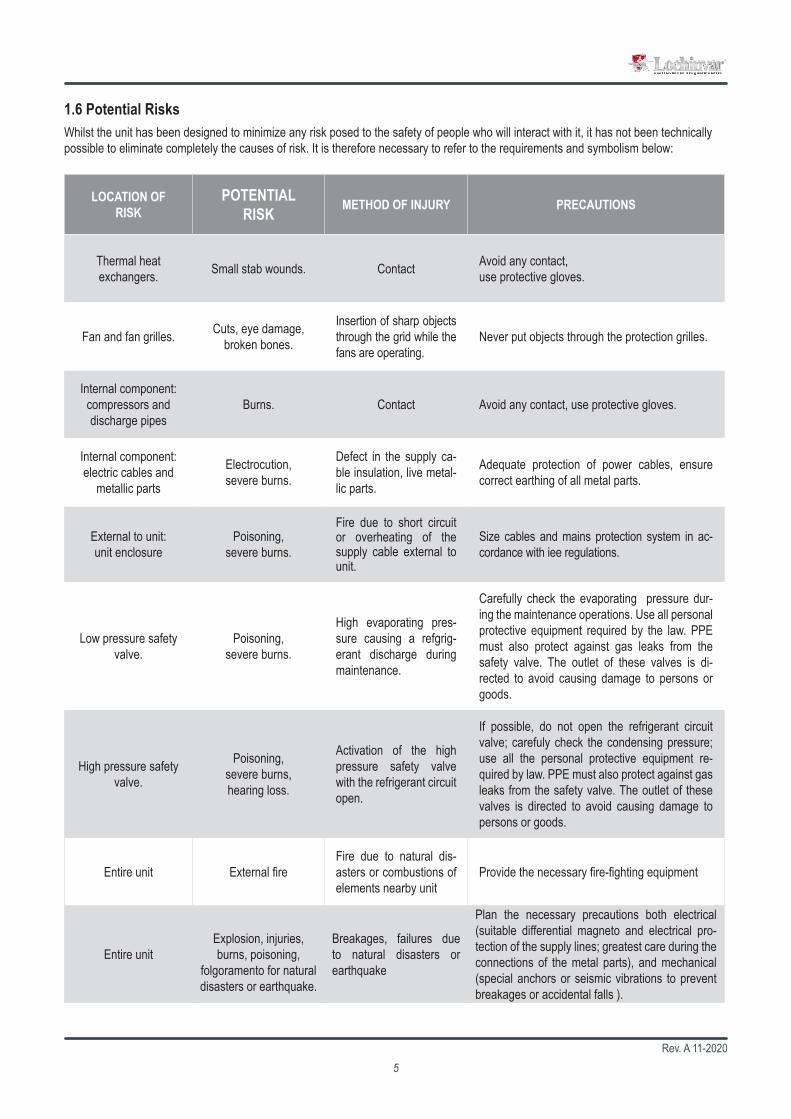
1.6 Potential RisksWhilst the unit has been designed to minimize any risk posed to the safety of people who will interact with it, it has not been technically possible to eliminate completely the causes of risk. It is therefore necessary to refer to the requirements and symbolism below:
LOCATION OF RISK
POTENTIAL RISK METHOD OF INJURY PRECAUTIONS
Thermal heat exchangers. Small stab wounds. Contact Avoid any contact,
use protective gloves.
Fan and fan grilles. Cuts, eye damage, broken bones.
Insertion of sharp objects through the grid while the fans are operating.
Never put objects through the protection grilles.
Internal component: compressors and discharge pipes
Burns. Contact Avoid any contact, use protective gloves.
Internal component: electric cables and
metallic parts
Electrocution, severe burns.
Defect in the supply ca-ble insulation, live metal-lic parts.
Adequate protection of power cables, ensure correct earthing of all metal parts.
External to unit: unit enclosure
Poisoning, severe burns.
Fire due to short circuit or overheating of the supply cable external to unit.
Size cables and mains protection system in ac-cordance with iee regulations.
Low pressure safety valve.
Poisoning, severe burns.
High evaporating pres-sure causing a refgrig-erant discharge during maintenance.
Carefully check the evaporating pressure dur-ing the maintenance operations. Use all personal protective equipment required by the law. PPE must also protect against gas leaks from the safety valve. The outlet of these valves is di-rected to avoid causing damage to persons or goods.
High pressure safety valve.
Poisoning, severe burns, hearing loss.
Activation of the high pressure safety valve with the refrigerant circuit open.
If possible, do not open the refrigerant circuit valve; carefuly check the condensing pressure; use all the personal protective equipment re-quired by law. PPE must also protect against gas leaks from the safety valve. The outlet of these valves is directed to avoid causing damage to persons or goods.
Entire unit External fireFire due to natural dis-asters or combustions of elements nearby unit
Provide the necessary fire-fighting equipment
Entire unit
Explosion, injuries, burns, poisoning,
folgoramento for natural disasters or earthquake.
Breakages, failures due to natural disasters or earthquake
Plan the necessary precautions both electrical (suitable differential magneto and electrical pro-tection of the supply lines; greatest care during the connections of the metal parts), and mechanical (special anchors or seismic vibrations to prevent breakages or accidental falls ).

Rev. A 11-20206
BANNEDA black symbol inside a red circle with a red diagonal indicates an action that should not be performed.
WARNINGA black graphic symbol added to a yellow triangle with black edges indicates danger.
ACTION REQUIREDA white symbol inserted in a blue circle indicates an action that must be done to avoid a risk.
The graphic symbol “warning” is qualified with additional safety information (text or other symbols).
Safety symbols combined in accordance with ISO 3864-2:
1.7 General Description of Symbols Used
Safety symbols combined in accordance with ISO 3864-2:

Rev. A 11-20207
GENERAL RISKObserve all signs placed next to the pictogram. The failure to follow directions may create a risk situation that may be injurious to the user.
ELECTRICAL HAZARDObserve all signs placed next to the pictogram.The symbol indicates components of the unit and actions described in this manual that could create an electrical hazard.
MOVING PARTSThe symbol indicates those moving parts of the unit that could create risk.
HOT SURFACESThe symbol indicates those components with high surface temperature that could create risks.
SHARP SURFACESThe symbol indicates components or parts that could cause stab wounds.
EARTH CONNECTIONThe symbol identifies Earthing connection points in the unit.
READ AND UNDERSTAND THE INSTRUCTIONSRead and understand the instructions of the machine before any operations.
RECOVER OR RECYCLE MATERIAL
1.8 Safety symbols used
The unit is not suitable for operations in environments:• excessively dusty or potentially explosive atmospheres;• where there are vibrations;• where there are electromagnetic fields;• where there are aggressive atmospheres
The machine is designed and built exclusively for the uses described in “Limitations of use” of the technical manual.Any other use is prohibited because it may pose a potential risk to the health of operators and users.
1.9 Limitations and prohibited use

Rev. A 11-20208
1LZT.0452.HA.XL.HH.2S.00-1B
42,40 A
Manufacturer: FO337725
The MXL Centre, 7 Lombard WayOX16 4TJ Banbury Oxfordshire
United Kingdom
400V-3ph-50Hz
25/2021
F.L.A. (A)Voltage-Phases-Frequency
LOW PRESSURE SIDE
Ì244150oÎ
F.L.I. (kW)
Weight
29,5 bar 45 bar
2088
PS
HIGH PRESSURE SIDE
PS
Design temperature
Contains fluorinated greenhouse gasses.
2
-10 °C
30,28 ton
Design temperature
Serial number
Manufacturing datePED Category
Matricola
Data di produzioneCategoria PED
Tipo refrigerante
Refrigerant type GWPFluid group
Gruppo fluido
Min Max LiqMin Max
LATO ALTA PRESSIONELATO BASSA PRESSIONE
Tensione-Fasi-Frequenza
Peso a vuoto
Temperatura di progetto Temperatura di progetto
CO Equivalent
CO2
2
EquivalenteCarica refrigerante
Refrigerant charge
Barcode
14,5 kgC1
C3 C4
C2
27,10 kW
Contiene gas fluorurati ad effetto serra.
50 °C-10 °C
R410A 2
0948
244150
244150
Heat pump
Pompa di calore
Max Gas
125 °C80 °C
Taratura organo di sicurezza
Safety device calibration
45 bar
The product label should never be removed from the unit.
1.10 Unit identificationEach unit has a rating plate that provides key information regarding the machine.The rating plate may differ from the one shown below as the example is for a standard unit without accessories.For all electrical information not provided on the label, refer to the wiring diagram.A facsimile of the label is shown below:
Rev. A 11-20209
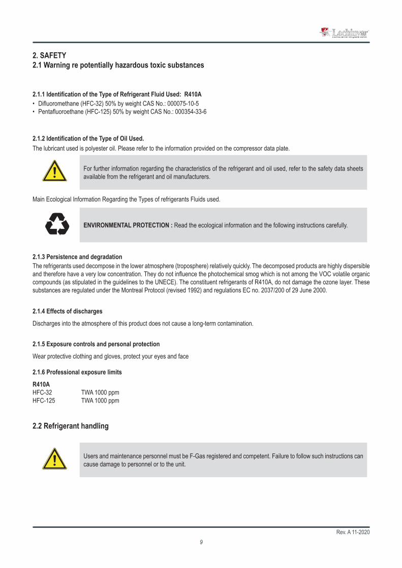
For further information regarding the characteristics of the refrigerant and oil used, refer to the safety data sheets available from the refrigerant and oil manufacturers.
2.1 Warning re potentially hazardous toxic substances
2.1.2 Identification of the Type of Oil Used.
2. SAFETY
The lubricant used is polyester oil. Please refer to the information provided on the compressor data plate.
ENVIRONMENTAL PROTECTION : Read the ecological information and the following instructions carefully.
2.1.3 Persistence and degradation
2.1.4 Effects of discharges
2.1.5 Exposure controls and personal protection
2.1.6 Professional exposure limits
2.2 Refrigerant handling
The refrigerants used decompose in the lower atmosphere (troposphere) relatively quickly. The decomposed products are highly dispersible and therefore have a very low concentration. They do not influence the photochemical smog which is not among the VOC volatile organic compounds (as stipulated in the guidelines to the UNECE). The constituent refrigerants of R410A, do not damage the ozone layer. These substances are regulated under the Montreal Protocol (revised 1992) and regulations EC no. 2037/200 of 29 June 2000.
Discharges into the atmosphere of this product does not cause a long-term contamination.
Wear protective clothing and gloves, protect your eyes and face
R410AHFC-32 TWA 1000 ppmHFC-125 TWA 1000 ppm
Main Ecological Information Regarding the Types of refrigerants Fluids used.
Users and maintenance personnel must be F-Gas registered and competent. Failure to follow such instructions can cause damage to personnel or to the unit.
2.1.1 Identification of the Type of Refrigerant Fluid Used: R410A• Difluoromethane (HFC-32) 50% by weight CAS No.: 000075-10-5• Pentafluoroethane (HFC-125) 50% by weight CAS No.: 000354-33-6

Rev. A 11-202010
2.3 Prevent inhalation of high vapor concentration
2.4 Procedures to be adopted in the event of accidental release of refrigerant
2.5 Main Toxicological Information Regarding the Type of refrigerant used2.5.1 InhalationA high atmospheric concentration can cause anaesthetic effects with possible loss of consciousness. Prolonged exposure may lead to irre-gular heartbeat and cause sudden death. Higher concentrations may cause asphyxia due to the reduced oxygen content in the atmosphere.
2.5.2 Contact with skinSplashes of nebulous liquid can produce frostbite. Probably not hazardous if absorbed trough the skin. Repeated or prolonged contact may remove the skin’s natural oils, with consequent dryness, cracking and dermatitis.
2.5.3 Contact with eyesSplashes of liquid may cause frostbite.
2.5.4 IngestionWhile highly improbable, may produce frostbite.
Atmospheric concentrations of refrigerant must be minimized and kept to a level that is below the occupational exposure limit. Vapor is heavier than air and can form dangerous concentrations near the ground where the ventilation rate is lower. Always ensure adequate venti-lation. Avoid contact with open flames and hot surfaces as this can cause toxic and irritating decomposition products to form. Avoid contact between liquid refrigerant and the eyes or skin.
Ensure suitable personal protection (especially respiratory protection) during cleaning operations.If deemed safe, isolate the source of the leak. If the leakage is small and if adequate ventilation is provided, allow the refrigerant to evapo-rate. If the loss is substantial ensure that measures are taken to adequately ventilate the area.Contain spilled material with sand, earth or other suitable absorbent material.Do not allow the refrigerant to enter drains, sewers or basements, as pockets of vapor can form.
2.6 First Aid Measures
2.6.1 Inhalation
2.6.2 Contact with skin
Move the person away from the source of exposure, keep him/her warm and let him/her rest. Seek medical assistance.
In case of contact with skin, wash immediately with lukewarm water. Thaw tissue using water. Remove contaminated clothing. Clothing may stick to the skin in case of frostbite. If irritation, swelling or blisters appear, seek medical assistance.
Adhere scrupulously to the warnings and first aid procedures indicated below.
2.6.3 Contact with eyesRinse immediately using an eyewash or clean water, keeping eyelids open, for at least ten minutes. Seek medical assistance.
2.6.4 IngestionDo not induce vomiting. If the injured person is conscious, rinse his/her mouth with water and make him/her drink 200-300ml of water. Seek immediate medical assistance.
2.6.5 Further medical treatmentTreat symptoms and carry out support therapy as indicated. Do not administer adrenaline or similar sympathomimetic drugs following exposure, due to the risk of cardiac arrhythmia.

Rev. A 11-202011
3. TECHNICAL CHARACTERISTICS3.1 Unit descriptionThe LZT series of high efficiency heat pumps has been specifically designed for use with radiant floor heating systems or those applications where it is necessary to have maximum efficiency when heating. They have been optimized on heating mode, are able to produce water up to 65°C and can operate down to -20°C ambient temperature. All versions are supplied with reverse cycle valve used for winter defrost; the HH version is suitable for use in those countries that have support schemes for use of heat pump technology for heating. The RV versions are also able to produce cold water. The HH heating only versions is factory set and locked to operate only in heating mode whilst. The noise in XL and NN versions is extremely low thanks to the use of a special floating vibration damping system which allows a noise reduction of about 10-12 dB(A).
3.1.1 FrameAll units are made from hot-galvanised sheet steel, painted with polyurethane powder enamel and stoved at 180°C to provide maximum protection against corrosion. The frame is self-supporting with removable panels. All screws and rivets used are made from stainless steel. The standard colour of the units is RAL9018.
3.1.2 Refrigerant circuitThe refrigerant utilised is R410A. The refrigerant circuit is assembled using internationally recognised brand name components with all brazing and welding being performed in accordance with ISO 97/23. The refrigerant circuit includes: sight glass, filter drier, two thermal expansion valves (one for cooling mode, one for heating mode) with external equalizer, 4 way reversing valve, check valves, liquid receiver, Schrader valves for maintenance and control, pressure safety device (for compliance with PED regulations). The circuit also includes an AISI316 stainless steel heat exchanger that is used as an economizer plus an additional expansion valve for refrigerant vapour injection.
3.1.3 CompressorsUnits use scroll compressors that are equipped with E.V.I. technology, a versatile method of improving system capacity and efficiency. EVI stands for “Enhanced Vapour Injection.” The technology involves injecting refrigerant vapour into the middle of the compression process, a procedure that significantly boosts capacity and efficiency. Each scroll compressor used in these units is similar to a two-stage compressor with built-in inter-stage cooling. The process begins when a portion of the condenser liquid is extracted and expanded through an expan-sion valve. The low temperature liquid/gas mixture produced is injected into a heat exchanger that operates as a sub cooler. Any liquid is evaporated and the vapour produced is superheated. The superheated vapour is then injected into an intermediate port in the scroll com-pressor. This cold vapour reduces the temperature of the compressed gas thus enabling the compressor to raise the pressure to levels (and temperatures) beyond that possible with a single stage scroll. The additional sub cooling of the main volume of liquid refrigerant increases the evaporator capacity. This compressor technology generates a larger pressure ratio between condensing and evaporating pressures, with significant performance improvement. In all units the compressors are connected in tandem. The compressors are all supplied with a crankcase heater and thermal overload protection by a klixon embedded in the motor winding. They are mounted in a separate enclosure in order to be separated from the air stream thus enabling them to be maintained even if the unit is operating. Access to this enclosure is by the front panel of the unit. The crankcase heater is always powered when the compressor is in stand-by.
3.1.4 Source heat exchangerThe source heat exchanger is made from 3/8” copper pipes and 0,1mm thick aluminium fins with the tubes being mechanically expanded into the aluminium fins in order to maximise heat transfer. Furthermore, the design guarantees a low air side pressure drop thus enabling the use of low rotation speed (and hence low noise) fans. All heat exchangers are supplied standard with fins hydrophilic coating.
3.1.5 FansThe fans are direct drive axial type with aluminium aerofoil blades, are statically and dynamically balanced and are supplied complete with a safety fan guard complying with the requirements of EN 60335. They are fixed to the unit frame via rubber antivibration mountings.In the LS versions the fans are 6 poles type (approx 900 rpm), in the XL versions the fans are 8 poles type (approx 600 rpm), in the NN versions the fans are 12 poles type (approx 450 rpm). The motors are fitted with integrated thermal overload protection and have a moisture protec-tion rating of IP 54.
3.1.6 User heat exchangersThe user heat exchanger is a braze welded, plate type heat exchanger, manufactured from AISI 316 stainless steel. The use of this type of exchanger results in a massive reduction of the refrigerant charge of the unit compared to a traditional shell-in-tube type. A further advan-tage is a reduction in the overall dimensions of the unit. The exchangers are factory insulated with flexible close cell material and can be fitted with an antifreeze heater (accessory). Each exchanger is fitted with a temperature sensor on the discharge water side for antifreeze protection.

Rev. A 11-202012
3.1.7 Electric enclosureThe enclosure is manufactured in order to comply with the requirements of the electromagnetic compatibility standards CEE EN60204. Access to the enclosure is achieved by removing the front panel of the unit. The following components are supplied as standard on all units: main switch, a sequence relay that disables the power supply in the event that the phase sequence is incorrect (scroll compressors can be damaged if they rotate in the wrong direction), thermal overloads (protection of pumps and fans), overload switches, control circuit automatic breakers, compressor contactors, automatic switches and pump contactors. The terminal board has volt free contacts for remote ON-OFF, Summer/ winter change over (heat pumps only) and general alarm.
3.1.8 MicroprocessorsAll units are supplied as standard with microprocessor controls. The microprocessor controls the following functions: control of the water temperature, antifreeze protection, compressor timing, compressor automatic starting sequence (For multiple compressors), alarm reset. The control panel is supplied with display showing all operational icons. The microprocessor is set for automatic defrost (when operating in severe ambient conditions) and for summer/ winter change over.The control also manages the anti-legionella program, the integration with other heating sources (electric heaters, boilers, solar panels etc), the operation of a three port modulating valve (for diverting to DHW or heating) and both the heating circuit pump and the domestic hot water circuit pump. If required (available as an option), the microprocessor can be configured in order for it to connect to a site BMS system thus enabling remote control and management. The Lochinvar technical department can discuss and evaluate, in conjunction with the customer, solutions using MODBUS protocols.
3.1.9 Control and protection devicesAll units are supplied with the following controls and protections: user water return temperature sensor, antifreeze protection temperature sensor installed on users water output, domestic hot water supply and return temperature sensors (only versions P2S), high pressure manual reset, low pressure automatic reset, compressor thermal protection, air fan, thermal protection, pressure transducer (used to opti-mize the defrost cycle and to adjust the fan speed depending on ambient conditions), flow switch. All units are also fitted with a temperature probe sensor with “Energy Saving” function, supplied in a separate plastic box, which can be used to stop the pump use during periods of stand-by, when the water temperature reaches the set point. Doing this the power consumption of the unit is strongly reduced. The probe sensor must be positioned in the hydraulic compensator present at the screening technique. The domestic hot water circuit (only versions P2S) is already equipped with this probe, but it must be installed in the user circuit.
3.1.10 User flow switchThe flow utility is installed as standard on all units and disables the operation of the unit in case of abnormal water flow in the system. The flow switch is made of a blade system fitted in the flow of the water; it is combined with two permanent magnets that assess the amount of water in transit and, in function of the measured parameter, enable or not the operation of the unit.
3.2 Versions
3.2.1 Version HHHH heating only versions are available in the P2U and P2S configuration only.
3.2.6 HE VersionHigh efficiency version, according to ERP2018 standard. Unit equipped with EC fans.
3.2.8 Version XLAll versions are supplied, as standard, with the latest ‘Floating Frame’ technology that completely isolates the compressors from the main casing, thereby eliminating vibration and noise from this source. The ‘Floating Frame’ is a special vibration and acoustic damping system that consists of a base plate and acoustic enclosure that houses the compressors. The base plate is separated from the supporting frame of the unit by soft steel springs that have a high damping power. Within the enclosure, the compressors are mounted on rubber shock ab-sorbers on the floating base plate. The enclosure is manufactured from galvanized steel sandwich panels that have a core of 30 mm thick, high density (25 kg/m3) mineral wool. The entire arrangement provides a double damping system and acoustic attenuation. The compressor refrigerant pipes are connected to the refrigerant circuit through “anaconda” flexible connections. Flexible connections are also used on the water pipework within the unit. The combination of these systems results in an overall noise reduction in the region of 10-12 dB(A).
3.2.10 Version P2U This is a two pipe version that can produce hot water for heating and cold water for cooling. The unit is used with two pipe water based change-over systems. It is not able to produce domestic hot water.
3.2.11 Version P2SThis is a two pipe version that can, in addition to producing hot water for heating and cold water for cooling, also generate domestic hot
Rev. A 11-202013
water. The controller has dual heating set points (heating and DHW) and can also control a three port diverting valve that directs the DHW to the cylinder. DHW production has priority irrespective of the mode of operation of the unit. The unit is normally used with two pipe water based change-over systems.
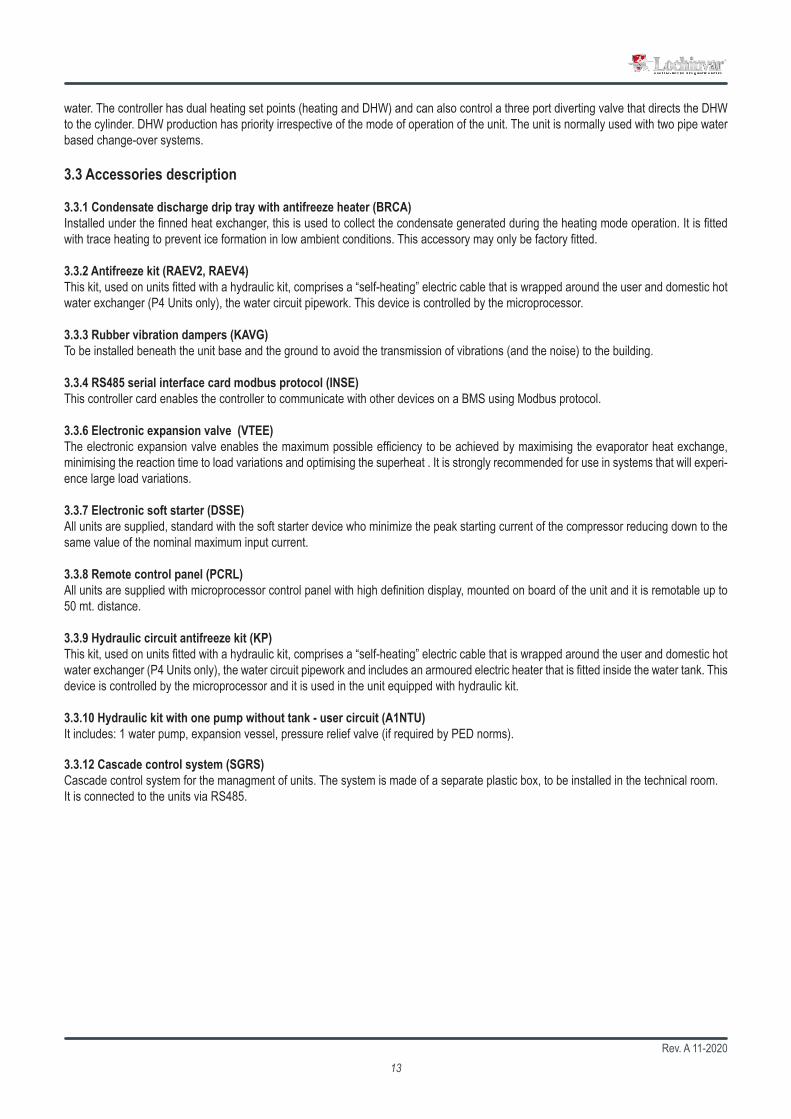
3.3 Accessories description
3.3.1 Condensate discharge drip tray with antifreeze heater (BRCA)Installed under the finned heat exchanger, this is used to collect the condensate generated during the heating mode operation. It is fitted with trace heating to prevent ice formation in low ambient conditions. This accessory may only be factory fitted.
3.3.2 Antifreeze kit (RAEV2, RAEV4)This kit, used on units fitted with a hydraulic kit, comprises a “self-heating” electric cable that is wrapped around the user and domestic hot water exchanger (P4 Units only), the water circuit pipework. This device is controlled by the microprocessor.
3.3.3 Rubber vibration dampers (KAVG)To be installed beneath the unit base and the ground to avoid the transmission of vibrations (and the noise) to the building.
3.3.4 RS485 serial interface card modbus protocol (INSE)This controller card enables the controller to communicate with other devices on a BMS using Modbus protocol.
3.3.6 Electronic expansion valve (VTEE)The electronic expansion valve enables the maximum possible efficiency to be achieved by maximising the evaporator heat exchange, minimising the reaction time to load variations and optimising the superheat . It is strongly recommended for use in systems that will experi-ence large load variations.
3.3.7 Electronic soft starter (DSSE)All units are supplied, standard with the soft starter device who minimize the peak starting current of the compressor reducing down to the same value of the nominal maximum input current.
3.3.8 Remote control panel (PCRL)All units are supplied with microprocessor control panel with high definition display, mounted on board of the unit and it is remotable up to 50 mt. distance.
3.3.9 Hydraulic circuit antifreeze kit (KP)This kit, used on units fitted with a hydraulic kit, comprises a “self-heating” electric cable that is wrapped around the user and domestic hot water exchanger (P4 Units only), the water circuit pipework and includes an armoured electric heater that is fitted inside the water tank. This device is controlled by the microprocessor and it is used in the unit equipped with hydraulic kit.
3.3.10 Hydraulic kit with one pump without tank - user circuit (A1NTU)It includes: 1 water pump, expansion vessel, pressure relief valve (if required by PED norms).
3.3.12 Cascade control system (SGRS)Cascade control system for the managment of units. The system is made of a separate plastic box, to be installed in the technical room. It is connected to the units via RS485.

Rev. A 11-202014
2,0
2,5
3,0
3,5
4,0
-15 -10 -5 0 5 10 15
10-20 -10 0 10 20 30 40 50
20
30
40
50
60
70
2,0
2,5
3,0
3,5
4,0
-15 -10 -5 0 5 10 15
10-20 -10 0 10 20 30 40 50
20
30
40
50
60
70
Pi
P
Pm+i
Pm
Ph
Pi
HXTEV
m +i
m
i
TEV
C.O.P.
The above graph shows the operation range of the EVI scroll compressors supplied in the units; at -20°C ambient the water outlet tempe-rature is still 52°C; this performance makes the installation of a heat pump suitable for any European condition.
Ambient temperature (°C)
Max Water Temperature (°C)
The efficiency of EVI compressors at low ambient conditions is about 25% higher than standard scroll compressors. The effect of this difference becomes even more evident in applications that require high hot water temperatures (i.e. when domestic hot water is required). In such applications the operational limits of a standard scroll compressor prevent it from producing the required hot water temperature at air ambient temperatures below 5°C.
The graph below shown the trend of the coefficient of performance C.O.P. compared with a standard scroll compressor (dotted line); EVI scroll compressor (Continuous curve).
Water production at 40°CWater production at 55°C
Water production at 40°C
Water production at 55°C
Ambient temperature (°C)
EVI stands for “Economised Vapour Injection.” The technology involves injecting refrigerant vapour into the middle of the compression process, a procedure that significantly boosts capacity and efficiency. Each scroll compressor used in these units is similar to a two-stage compressor with built-in inter-stage cooling. The process begins when a portion of the condenser liquid is extracted and expanded through an expansion valve. The low temperature liquid/gas mixture produced is injected into a heat exchanger that operates as a sub cooler. Any liquid is evaporated and the vapour produced is superheated. The superheated vapour is then injected into an intermediate port in the scroll compressor. This cold vapour reduces the temperature of the compressed gas thus enabling the compressor to raise the pressure to levels (and temperatures) beyond that possible with a single stage scroll. The additional sub cooling of the main volume of liquid refrigerant increases the evaporator capacity. This compressor technology generates a larger pressure ratio between condensing and evaporating pressures, with significant performance improvement. Using this technology enables the units to produce hot water up to 65°C and the ability to operate down to -20°C ambient temperature.
3.4 What is the E.V.I. technology (enhanced vapour injection)

Rev. A 11-202015
Heating only version (HH)
The refrigerant data may change without notice. It is therefore necessary to refer always to the silver label placed on the unit.
Model LAHP-252HT
LAHP-302HT
LAHP-432HT
LAHP-492HT
LAHP-602HT
LAHP-752HT
LAHP-852HT
LAHP-1002HT
LAHP-1202HT
Efficiency data - part L2Heating capacity (EN14511)1 kW 24 30 41.2 49.2 57.4 65.6 79.9 87.2 100.7Total power input (EN14511)1 kW 5.2 6.8 9.2 11.8 12.9 15.1 17.8 19.4 23.5COP (EN14511)1 W/W 4.64 4.39 4.49 4.16 4.57 4.35 4.49 4.49 4.29Efficiency data - ErP and energy labelEnergy label rating low temperature A++ A++ A++ A++ A++ A++ A++ A++ A++SCOP low temperature 4.1 3.87 4 3.84 4.21 4.16 4.04 4.06 3.93Seasonal efficiency low temperature % 161 151.8 157.1 150.6 165.4 163.4 158.7 159.5 154Energy label rating high temperature A++ A+ A++ A++ A++ A++ A++ A++ A++SCOP high temperature 3.24 3.14 3.24 3.16 3.38 3.29 3.26 3.33 3.25Seasonal efficiency high temperature % 126.5 122.7 126.6 123.4 132 128.6 127.3 130 126.9General dataRefrigerant R410A R410A R410A R410A R410A R410A R410A R410A R410APower supply V/Ph/Hz 400/3+N/50Maximum input current standard unit A 20.6 24 34.2 39.4 44.2 54.2 67.6 68.6 77.4Peak input current standard unit A 62.9 83.1 119 149 141 168 209 210 208Fans No 2 2 2 2 2 2 2 2 2Compressors/refrigerant circuits No 2/1 2/1 2/1 2/1 2/1 2/1 2/1 2/1 2/1Sound power level2 dB(A) 70 72 73 74 73 73 74 75 75Sound pressure level3 dB(A) 38 40 41 42 41 41 42 43 431) External air+7C 30/35 flow2) Average conditions according to EU/811/20133) Sound power level in accordance with ISO3744
3.5 Technical data
Rev. A 11-202016
20
30
40
50
60
70
-30 -20 -10 0 10 20 30 40 50
12
21
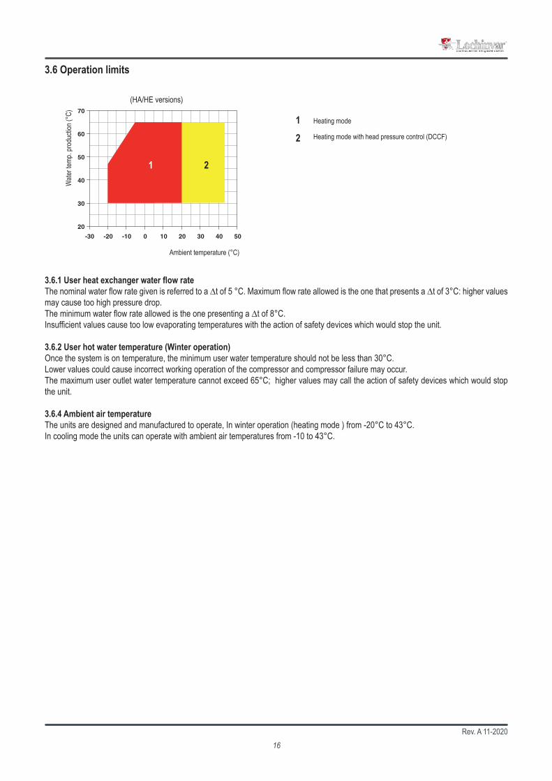
3.6 Operation limits
3.6.1 User heat exchanger water flow rateThe nominal water flow rate given is referred to a ∆t of 5 °C. Maximum flow rate allowed is the one that presents a ∆t of 3°C: higher values may cause too high pressure drop. The minimum water flow rate allowed is the one presenting a ∆t of 8°C. Insufficient values cause too low evaporating temperatures with the action of safety devices which would stop the unit.
3.6.2 User hot water temperature (Winter operation)Once the system is on temperature, the minimum user water temperature should not be less than 30°C. Lower values could cause incorrect working operation of the compressor and compressor failure may occur. The maximum user outlet water temperature cannot exceed 65°C; higher values may call the action of safety devices which would stop the unit.
3.6.4 Ambient air temperatureThe units are designed and manufactured to operate, In winter operation (heating mode ) from -20°C to 43°C.In cooling mode the units can operate with ambient air temperatures from -10 to 43°C.
Heating mode
Ambient temperature (°C)
Wate
r tem
p. pr
oduc
tion (
°C)
(HA/HE versions)
Heating mode with head pressure control (DCCF)
Rev. A 11-202017
All units are supplied as standard with evaporating/condensing pressure control. This feature allows the unit to operate in heating mode above 15°C and in cooling mode below 20°C ambient temperature. The device monitors the evaporating/condensing pressure and maintains it at a constant level by modulating the airflow. It can also be used to reduce noise emission when ambient temperatures are lower (eg. at night).
Units are designed and manufactured to European safety and technical standards. The units have been designed exclusively for heating, cooling and domestic hot water production (D.H.W.). The units must be used for this specific purpose only. The Company will not be liable for claims for damage caused to persons, animals or material goods or property caused by improper installation, adjustment and maintenance or improper use. Any use not specified in this manual is prohibited.
In case of operations outside of these values, please contact the company.
In WINTER mode, the unit can be started with external air of -20°C and cold inlet water (about 20°C). Such a configuration is allowed only for a short time and only to bring the plant to the right temperature. To reduce this setting time, we suggest to install a 3-way valve which allows to by-pass water from the user to the plant till the standard conditions are reached.
If the unit is installed in particularly windy areas, it will be necessary to provide some windbreaker barriers to avoid any malfunction. We suggest to install the barriers only if the wind exceeds 2,5m/s.
The units, in their standard configuration, are not suitable for installation in saline environments.
3.7 Domestic hot water productionThe production of domestic hot water through heat pump is a sensitive issue that deserves proper consideration. There are several systems of domestic hot water production by using heat pumps, each of which brings advantages and disadvantages. It is not subject of this manual to deal with the matter in depth and in the case, please contact the company for all the appropriate solutions.
Rev. A 11-202018
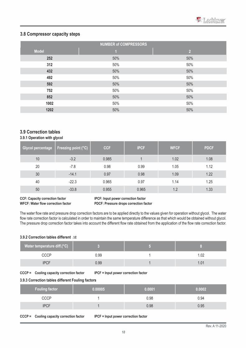
10 -3.2 0.985 1 1.02 1.08
20 -7.8 0.98 0.99 1.05 1.12
30 -14.1 0.97 0.98 1.09 1.22
40 -22.3 0.965 0.97 1.14 1.25
50 -33.8 0.955 0.965 1.2 1.33
3 5 8
CCCP 0.99 1 1.02
IPCF 0.99 1 1.01
0.00005 0.0001 0.0002
CCCP 1 0.98 0.94
IPCF 1 0.98 0.95
1 2252 50% 50%312 50% 50%432 50% 50%492 50% 50%592 50% 50%752 50% 50%852 50% 50%
1002 50% 50%1202 50% 50%
Glycol percentage Freezing point (°C) CCF IPCF WFCF PDCF
Water temperature diff.(°C)
CCCP = Cooling capacity correction factor IPCF = Input power correction factor
Fouling factor
CCCP = Cooling capacity correction factor IPCF = Input power correction factor
3.9.1 Operation with glycol3.9 Correction tables
3.9.2 Correction tables different ∆t
3.9.3 Correction tables different Fouling factors
CCF: Capacity correction factor IPCF: Input power correction factor WFCF: Water flow correction factor PDCF: Pressure drops correction factor
The water flow rate and pressure drop correction factors are to be applied directly to the values given for operation without glycol. The water flow rate correction factor is calculated in order to maintain the same temperature difference as that which would be obtained without glycol. The pressure drop correction factor takes into account the different flow rate obtained from the application of the flow rate correction factor.
NUMBER of COMPRESSORSModel
3.8 Compressor capacity steps

Rev. A 11-202019
HA / XL
Mod.Lw Lp
63 125 250 500 1K 2K 4K 8K dB dB(A) dB(A)dB dB dB dB dB dB dB dB252/HA/XL 85,1 76,3 70,2 68,7 67,6 62,2 58,8 49,7 85,9 72 40312/HA/XL 85,1 76,3 70,2 68,7 67,6 62,2 58,8 49,7 85,9 72 40432/HA/XL 86,1 77,3 71,2 69,7 68,6 63,2 59,8 50,7 86,9 73 41492/HA/XL 87,1 78,3 72,2 70,7 69,6 64,2 60,8 51,7 87,9 74 42592/HA/XL 87,1 78,3 72,2 70,7 69,6 64,2 60,8 51,7 87,9 74 42752/HA/XL 87,1 78,3 72,2 70,7 69,6 64,2 60,8 51,7 87,9 74 42852/HA/XL 87,1 78,3 72,2 70,7 69,6 64,2 60,8 51,7 87,9 74 42
1002/HA/XL 88,1 79,3 73,2 71,7 70,6 65,2 61,8 52,7 88,9 75 431202/HA/XL 88,1 79,3 73,2 71,7 70,6 65,2 61,8 52,7 88,9 75 43
3.10 Sound data
Lw: Sound power level according to ISO 3744.Lp: Sound pressure level measured at 10 mt from the unit in free field conditions direction factor Q=2 according to ISO 3744.
Octave bands (Hz)

Rev. A 11-202020
When operating and maintaining the unit, use the following personal protective equipment listed below as required by law.
Protective footwear.
Eye protection.
Protective gloves.
Respiratory protection.
Hearing protection.
4.3 Personal protective equipment
4.2 Health and safety Considerations
The workplace must be kept clean, tidy and free from objects that may prevent free movement. Appropriate ligh-ting of the work place shall be provided to allow the operator to perform the required operations safely. Poor or too strong lighting can cause risks.
Ensure that work places are always adequately ventilated and that respirators are working, in good condition and comply fully with the requirements of the current regulations.
Before undertaking any task the operator must be fully trained in the operation of the machines to be used and their controls. They must also have read and be fully conversant with all operating instructions.
4. INSTALLATION
4.1 General safety guidelines and and use of symbols
All maintenance must be performed by TRAINED personnel and be in accordance with all national and local regu-lations.
The installation and maintenance of the unit must comply with the local regulations in force at the time of the installation.
Avoid contact and do not insert any objects into moving parts.

Rev. A 11-202021
4.4 InspectionWhen installing or servicing the unit, it is necessary to strictly follow the rules reported on this manual, to conform to all the specifications of the labels on the unit, and to take any possible precautions of the case. Not observing the rules reported on this manual can create dangerous situations. After receiving the unit, immediately check its integrity. The unit left the factory in perfect conditions; any eventual damage must be questioned to the carrier and recorded on the Delivery Note before it is signed. Lochinvar must be informed within 24 hours of delivery of any damage along with pictures so this damage can be assessed.
Before accepting the unit check:• The unit did not suffer any damage during transport;
• The delivered goods are conforming to what shown in the delivery note.
In Case of Damage• List the damage on the delivery note• Inform the Company of the extent of the damage within 24 hours. After this time any claim will not be considered.• A full written report is required for cases of severe damage.
4.5 StorageUnits should be stored under cover and ideally, should remain in their packaging. The tools that are supplied for opening the electrics box should be formally transferred to the person responsible for the plant.
Packaging could be dangerous for the operators.
The packaging materials should be seperated and sent for disposal or possible recycling to specialist waste companies.
4.6 Unpacking
It is advisable to leave packaged units during handling and remove it before the installation.The packaging must be removed carefully to prevent any possible damage to the machine.The materials constituting the packaging may be different in nature (wood, cardboard, nylon, etc.).
4.5.1 ShipmentThe shipment must be carried out by authorised carriers and the characteristics of the vehicle used must be such as to avoid damaging the machinery transported/to be transported, neither during loading and unloading nor during transport. If the roads to be driven are irregular, the vehicle must be fitted with special suspensions or internal walls in order not to damage the unit during the shipment.
The maximum ambient temperature for storage/shipment is +45°C and the minimum is -20°C,

Rev. A 11-202022
4.7 Lifting and handlingWhen unloading the unit, it is strongly recommended that sudden movements are avoided in order to protect the refrigerant circuit, copper tubes or any other unit component. Units can be lifted by using a forklift or, alternatively, using belts. Take care that the method of lifting does not damage the side panels or the cover. It is important to keep the unit horizontal at all time to avoid damage to the internal components.
The Source heat exchangers fins are sharp. Use protection gloves.
4.8 Location and minimum technical clearancesAll units are designed for external installation : any overhang above the unit and location near trees, if they partially cover the unit,must be avoided in order to prevent air by-pass. It is advisable to create a proper mounting plinth, with a size similar to the unit foot-print. Unit vibration level is very low: it is advisable however, to install vibration dampers (spring or rubber) between the plinth and the unit base-frame to keep vibrations at a very low level. It is vital to ensure adequate air volume to the source fan. Re-circulation of discharge air must be avoided; failure to observe this point will result in poor performance or activation of safety controls. For these reasons it is necessary to observe the following clearances:
The unit has to be installed such that maintenance and repair is possible. The warranty does not cover costs for the provision of lifting apparatus, platforms or other lifting systems required to perform repairs during warranty period.
The installation site should be chosen in accordance with EN 378-1 and 378-3 standards. When choosing the installation site, all risks caused by accidental refrigerant leakage should be taken into consideration.
All air to water heat pumps, during defrost mode, produce condensate at the base of the source heat exchanger. If the ambient temperature is below 0°C the water may freeze, creating a thick layer of ice within the unit. This layer of ice, in specific conditions, may damage the heat exchanger and therefore, to guarantee correct operation of the units it is highly recommended to raise the unit of a minimum amount (F). This recommendation becomes more important if the unit is to be installed in a location that is subject to heavy snowfall.

Rev. A 11-202023
B
C
A
Legend Data Unit
Amicus HT heat pump model
LAHP-252HT
LAHP-302HT
LAHP-432HT
LAHP-492HT
LAHP-602HT
LAHP-752HT
LAHP-852HT
LAHP-1002HT
LAHP-1202HT
A Height mm 1466 1466 1676 1676 1839 1839 1892 1892 1892
B Length mm 1915 1915 2115 2115 2905 2905 2905 2905 2905
C Width mm 875 875 875 875 1146 1146 1145 1145 1145
Weight Kg 570 590 720 730 1080 1090 1140 1170 1250
Amicus HT LAHP252 to LAHP1202

Rev. A 11-202024
ØMØD
ØE
H
N G
LA
F
CB
1
A
AA
sez A - A
F
Mod. A B C D E F G H L M N252÷312 88 mm 52 mm 41 mm 25 mm 11 mm 67 mm 10 mm M12 65 mm 74,5 mm 5,5 mm432÷602 88 mm 52 mm 41 mm 25 mm 11 mm 67 mm 10 mm M12 65 mm 74,5 mm 5,5 mm752÷1202 88 mm 52 mm 41 mm 25 mm 11 mm 67 mm 10 mm M12 65 mm 74,5 mm 5,5 mm
4.9 Installation of rubber vibration dampers (KAVG)
All units should be installed on vibration dampers in order to prevent the transmission of vibration to the supporting surface and reduce the noise level. Rubber vibration dampers are available as an option in the catalogue. The vibration dampers (optional) are supplied by the factory in separate packaging.
4.10 Serial interface card RS485 (INSE)Supervision system interface (MODBUS RS485 available only)This system allows you to remotely monitor all parameters of the unit and change their values.It is necessary to respect the polarity of the wiring as shown in the diagram. Any reversal of polarity will result in the non-functioning unit. The supervision connectivity cable must be telephone one type 2x0, 25 mm2.The unit is configured at the factory with serial address 1. In case of using the MODBUS system, you can request the list of variables by contacting the assistance.

Rev. A 11-202025
≥ 35
mm
4 x 1” F
It is recommended that a heating cable be installed in the condensate drip tray discharge pipe to prevent freezing of the water inside the pipe itself, as this can lead to a malfunction of the unit.
The heating cable that is to be inserted in the discharge pipe must have a protection degree IP67 with a specific heating capacity of a minimum of 35W per linear metre. It is also recommended that the discharge pipe be insula-ted with closed cell type insulation having a minimum thickness of 15 mm.
4.11.1 Installation of the heating cable
Discharge pipe
Heating cable
Insulation
Nella linea di scarico deve essere realizzato un sifone che dovrà avere battente minimo pari alla prevalenza in aspirazione del ventilatore, in ogni caso mai inferiore a 35 mm.The condensate drain line should have a water trap which may have minimum flying height equal to the suction of the fan, in any case never less than 35 mm.
4.11 Installation of condensate drip tray (BRCA)
In all the units can be installed a drip tray that, positioned underneath the source heat exchanger (finned coil) and above the base frame, recovers all water generated by the unit when in heating and domestic hot water working mode. The drip tray is supplied with a self-heating antifreeze kit that melts the any ice present in the drip tray. The drip tray is supplied with a discharge connection that must be connected to a discharge pipe.
In heating and domestic hot water mode, the unit can produce a quantity of condensate, depending upon the am-bient conditions and the working hours. This condensate may freeze in severe ambient conditions. The unit must therefore be installed in such a way as to prevent a slipping hazard to the user or third parties due to the presence of ice around the heat pump.
Installing the condensate drip tray on site may be difficult. We recommend that you request the BRCA accessory when ordering the unit so that it can be installed at the factory.

Rev. A 11-202026
OKNO
System return water must be fitted to the connection labelled: ”USER WATER IN” as incorrect connection can damage the heat exchanger by freezing.
It is compulsory to install on the USER WATER IN connection, a water strainer with a mesh not larger than 1 mm. Fitting this filter is COMPULSORY and the warranty will be invalidated if it is removed. The filter must be kept clean and checked periodically.
All units are factory supplied with a flow switch; the flow switch MUST BE FITTED in the pipework connection labelled “USER WATER OUT”. If the flow switch is altered, removed, or the water filter omitted on the unit, the warranty will be invalidated.
The water flow through the heat exchangers of the unit should not be fall below Δt 8°C measured at the following conditions: Heating mode: 7°C Dry bulb ambient temperature, 35°C water outlet temperature; Cooling mode: 35°C dry bulb ambient temperature, 7°C water outlet temperature.
4.13 Chemical characteristics of the waterThe system is to be filled with clean water and vented after a full flushing operation has been performed; the water should have the following characteristics :
PH 6-8 Total Hardness Lower Than 50 ppmElectric conductibility Lower Than 200 mV/ cm (25°C) Sulphur ion None
Chlorine ions Lower Than 50 ppm Ammonia ion NoneSulphuric acid ions Lower Than 50 ppm Silicon ion Lower Than 30 ppm
Total Iron Lower Than 0,3 ppm
4.12 Hydraulic connectionsThe water pipe-work must be installed in accordance with national and local regulation and can be made from copper, steel, galvanized steel or PVC. The Pipework must be designed to cater for the nominal water flow and the hydraulic pressure drops of the system, a maxi-mum pressure drop of 300 Pa/m run being typical. All pipes must be insulated with closed-cell material of adequate thickness. The hydraulic piping should includes:• Pockets for temperature sensor to measure the temperature in the system.• Flexible joints, to isolate the unit from the rest of the system.• Temperature and pressure gauges for maintenance and servicing operations.• Shut-off manual valves to isolate the unit from the hydraulic circuit.• Metallic filters to be mounted on the inlet pipe with a mesh not larger than 1 mm.• Vent valves, expansion tank with water filling, discharge valve.

Rev. A 11-202027
E
E
A I
I
B B
B
M
G F C
H
L
CDB
E
E
A
I
I
B B
B
M
G F C
H
L
CD
B
E
E
A
I
I
B B
B
M
G F C
H
L
CD
B
E
E E
A
I
I
B
B B
M
L
C
D
E
E
E
E
A
B
G F C
H
L
CD
B
G F C
H
I
B
BN*
O*
MC
E
G F C
H
A I
B
I
BI
B
L D
E
E
E
E
A
B
G F C
H
L
CD
B
I
B
B
O
N*
*
MC
M
N*
O*
M
N*
O*
A I
B
I
BI
B
L D
N *
O*
4.14 Hydraulic components
The water pump must be installed with the supply side toward the water inlet connection of the unit.
4.14.1 P2S Versions P2U Versions
User Circuit
4.14.2 P2S Versions + A1NTU P2U Versions + A1NTU
User Circuit

Rev. A 11-202028
252 312 432 492 592 752 852 1002 1202250 300 425 510 550 680 750 890 1025
252 312 432 492 592 752 852 1002 1202250 300 425 510 550 680 750 890 1025
4.15 User circuit minimum water content
Heat pump units need a minimum water content inside the user circuit in order to guarantee the correct functioning of the unit. A correct water content reduces the n° of starts-and-stops of the compressors and this extends the operating life of the unit and allows a reduced reduction of the hot water temperature during the defrosting cycle.For these reason it’s necessary to guarantee to the unit the following minimum water contents in the user circuit:Recommended water content : 15l/kWRecommended minimum water content : 20 lt. x Thermal power ( kW ) / Number of compressors.
The minimum domestic hot water circuit content shown in the above table shows the minimum water content required by the system to guarantee the correct operation of the unit in terms of the acceptable number of starts of the compressors and the minimum allowed working time per cycle. The above values do not guarantee the availability and temperature of domestic hot water; the correct volume MUST be calculated based upon the domestic hot water system type and on the user requirements. Please contact technical support team for informa-tion regarding this.
If the fluid in the circuit contains anti-freeze, it MUST not be allowed to run away to drain. It must be collected for possible re-cycling or for correct disposal.
4.16 Minimum domestic hot water circuit content
4.17 Filling the hydraulic circuit
4.18 Emptying the installation
• Before filling, check that the installation drain valve is closed.• Open all pipework, heat pump and terminal unit air vents.• Open the shut off valves.• Begin filling, slowly opening the water valve in the filling group outside the unit.• When water begins to leak out of the terminal air vent valves, close them and continue filling until the pressure gauge indicates a pressure
of 1.5 bars.
The installation should be filled to a pressure of between 1 and 2 bars. It is recommended that this operation be repeated after the unit has been operating for a number of hours (due to the presence of air bubbles in the system). The pressure of the installation should be checked regularly and if it drops below 1 bar, the water content should be topped-up. If frequent top-ups are required, check all connections for leaks.
• Before emptying, place the mains switch in the “Off” position.• Make sure the filling group valve is closed.• Open the drainage valve outside the unit and all the installation and terminal air vent valves.
The minimum domestic hot water circuit content required is:Model
Minimum water content hydraulic circuit (l)
ModelMinimum water content winter mode (l)
Rev. A 11-202029
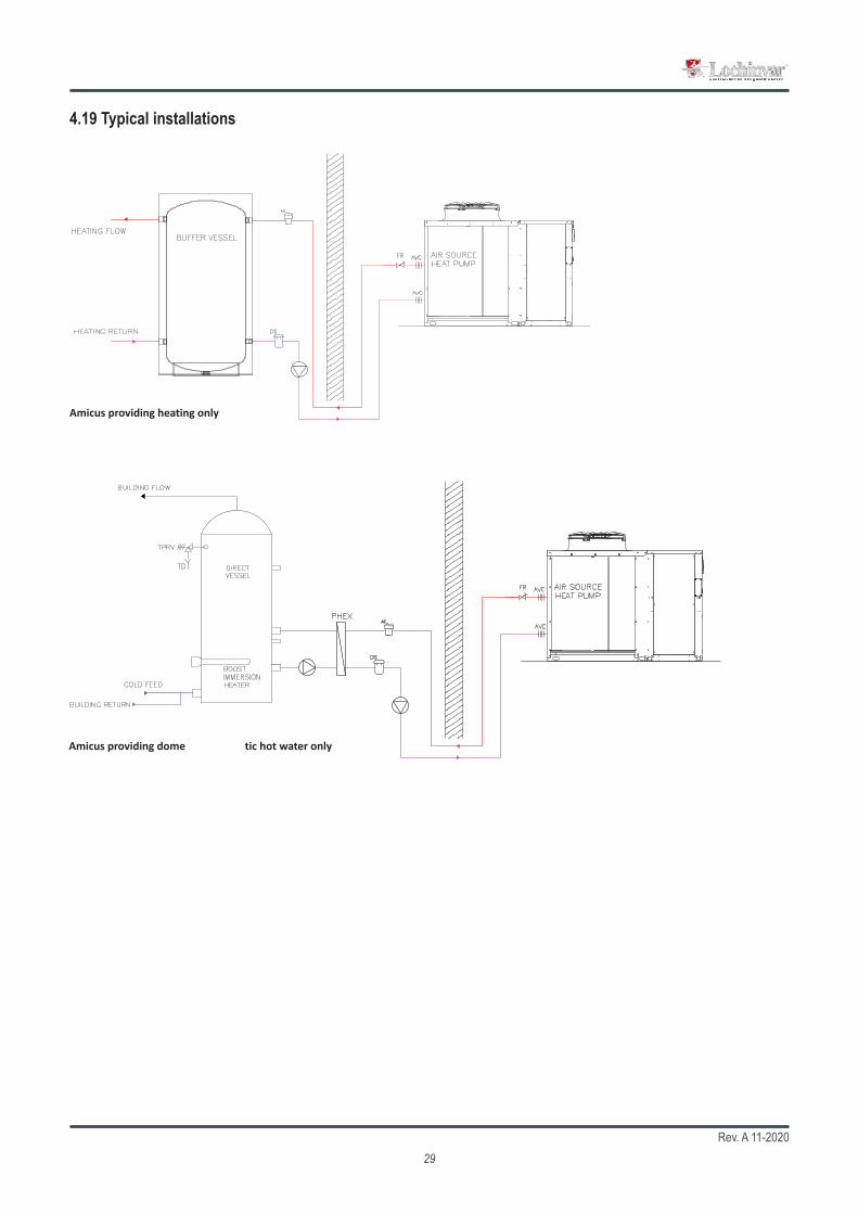
4.19 Typical installations
This drawing shows a typical layout, Some system componentsremoved for clarity. This drawing is for guidance only.
7 Lombard Way Telephone - +44(0)1295 269981The MXL Centre Fax - +44(0)1295 271640Banbury E Mail - [email protected] 4TJ Internet - www.lochinvar.ltd.uk
Lochinvar Ltd reserves the right to change specifications without prior notice.
All necessary additional valves and fittings to be determined by those otherthan Lochinvar Ltd.
Lochinvar Limited may provide technical advice and guidance to assist withbest practice, optimisation and installation of Lochinvar products; however, wewill not be liable for any duties as Designers under Construction (Design andManagement Regulations 2015). In all cases where information is provided,the customer must assess and manage risks associated with the technicalinformation and advice provided.
Description :
REV
DRAWING NO.
SHEET SIZE SCALE
DRAWN CHKD DATE DETAIL
1
1 x ASHP working with a buffer provding heating
SH SA 22/01/21
A3 NTS
Lochinvar LtdEV EXPANSION VALVEEXV EXPANSION VESSELAVM ANTI VIBRATION MOUNTIV ISOLATION VALVENRV NON RETURN VALVEAS AIR SEPARATORDS DIRT SEPARATORPMP PUMPAV AIR VENTFR FLOW REGULATOR/COMMISSIONING SETAVC ANTI VIBRATION COUPLINGTS1/TS2 ASHP TEMP SENSORSBTS TANK TEMP SENSORHL HIGH LIMIT STATFSW FLOW SWITCHTPRV TEMP AND PRESSURE RELIEF VALVETD TUNDISHSTR IN-LINE STRAINER (INLET SIDE)DV DRAIN VALVEPRV PRESSURE REDUCING VALVETP TEMP/PRESSURE GAUGEDCV DOUBLE CHECK VALVE3PV THREE PORT VALVE
Amicus providing heating only
This drawing shows a typical layout, Some system componentsremoved for clarity. This drawing is for guidance only.
7 Lombard Way Telephone - +44(0)1295 269981The MXL Centre Fax - +44(0)1295 271640Banbury E Mail - [email protected] 4TJ Internet - www.lochinvar.ltd.uk
Lochinvar Ltd reserves the right to change specifications without prior notice.
All necessary additional valves and fittings to be determined by those otherthan Lochinvar Ltd.
Lochinvar Limited may provide technical advice and guidance to assist withbest practice, optimisation and installation of Lochinvar products; however, wewill not be liable for any duties as Designers under Construction (Design andManagement Regulations 2015). In all cases where information is provided,the customer must assess and manage risks associated with the technicalinformation and advice provided.
Description :
REV
DRAWING NO.
SHEET SIZE SCALE
DRAWN CHKD DATE DETAIL
1
1 x ASHP Providing DHW
SH SA 22/01/21
A3 NTS
Lochinvar LtdEV EXPANSION VALVEEXV EXPANSION VESSELAVM ANTI VIBRATION MOUNTIV ISOLATION VALVENRV NON RETURN VALVEAS AIR SEPARATORDS DIRT SEPARATORPMP PUMPAV AIR VENTFR FLOW REGULATOR/COMMISSIONING SETAVC ANTI VIBRATION COUPLINGTS1/TS2 ASHP TEMP SENSORSBTS TANK TEMP SENSORHL HIGH LIMIT STATFSW FLOW SWITCHTPRV TEMP AND PRESSURE RELIEF VALVETD TUNDISHSTR IN-LINE STRAINER (INLET SIDE)DV DRAIN VALVEPRV PRESSURE REDUCING VALVETP TEMP/PRESSURE GAUGEDCV DOUBLE CHECK VALVE3PV THREE PORT VALVE
Amicus providing domestic hot water only
Rev. A 11-202030
4.20 Electric connections: preliminary safety information
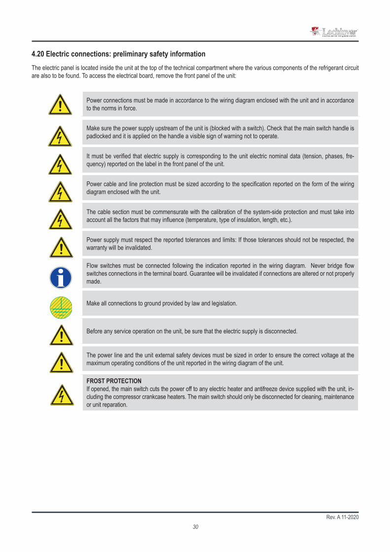
Power connections must be made in accordance to the wiring diagram enclosed with the unit and in accordance to the norms in force.
Make sure the power supply upstream of the unit is (blocked with a switch). Check that the main switch handle is padlocked and it is applied on the handle a visible sign of warning not to operate.
It must be verified that electric supply is corresponding to the unit electric nominal data (tension, phases, fre-quency) reported on the label in the front panel of the unit.
Power cable and line protection must be sized according to the specification reported on the form of the wiring diagram enclosed with the unit.
The cable section must be commensurate with the calibration of the system-side protection and must take into account all the factors that may influence (temperature, type of insulation, length, etc.).
Power supply must respect the reported tolerances and limits: If those tolerances should not be respected, the warranty will be invalidated.
Flow switches must be connected following the indication reported in the wiring diagram. Never bridge flow switches connections in the terminal board. Guarantee will be invalidated if connections are altered or not properly made.
Make all connections to ground provided by law and legislation.
Before any service operation on the unit, be sure that the electric supply is disconnected.
The power line and the unit external safety devices must be sized in order to ensure the correct voltage at the maximum operating conditions of the unit reported in the wiring diagram of the unit.
FROST PROTECTIONIf opened, the main switch cuts the power off to any electric heater and antifreeze device supplied with the unit, in-cluding the compressor crankcase heaters. The main switch should only be disconnected for cleaning, maintenance or unit reparation.
The electric panel is located inside the unit at the top of the technical compartment where the various components of the refrigerant circuit are also to be found. To access the electrical board, remove the front panel of the unit:
Rev. A 11-202031
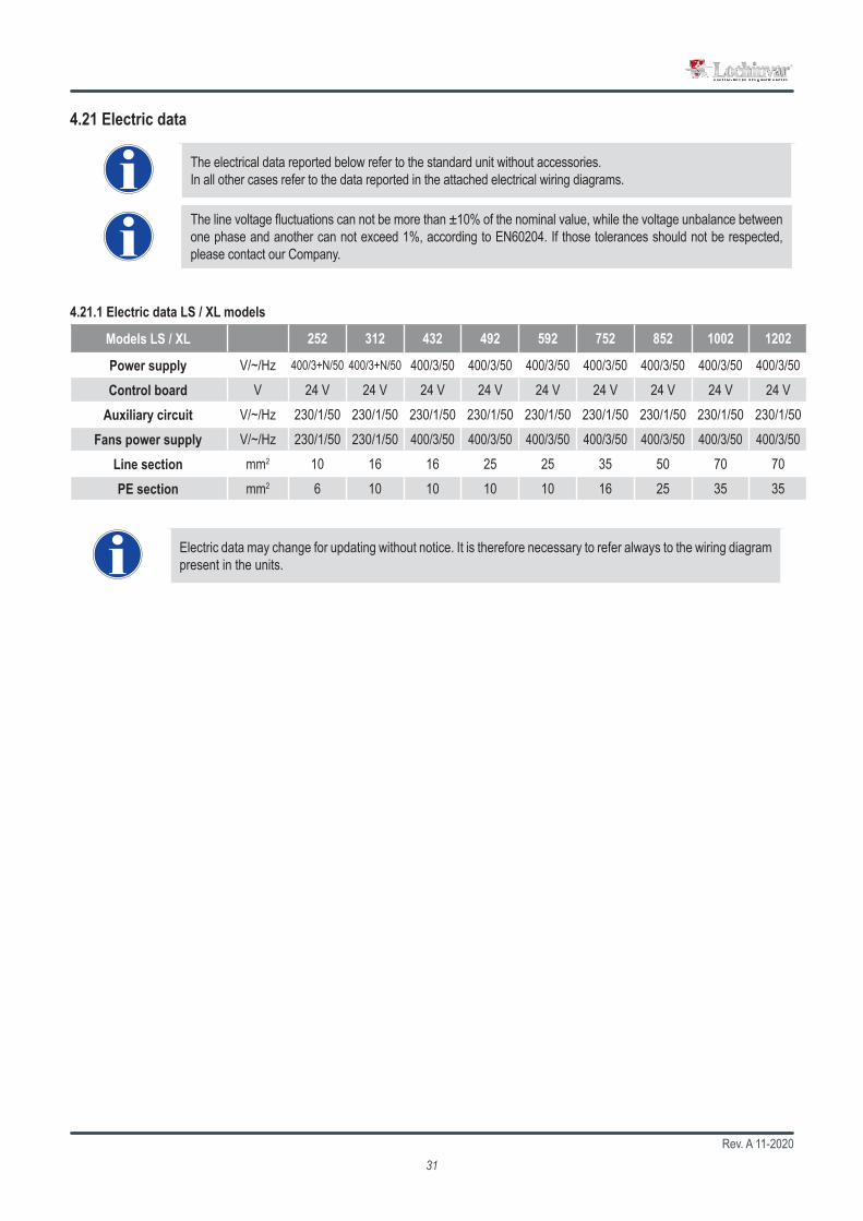
252 312 432 492 592 752 852 1002 1202
V/~/Hz 400/3+N/50 400/3+N/50 400/3/50 400/3/50 400/3/50 400/3/50 400/3/50 400/3/50 400/3/50V 24 V 24 V 24 V 24 V 24 V 24 V 24 V 24 V 24 V
V/~/Hz 230/1/50 230/1/50 230/1/50 230/1/50 230/1/50 230/1/50 230/1/50 230/1/50 230/1/50V/~/Hz 230/1/50 230/1/50 400/3/50 400/3/50 400/3/50 400/3/50 400/3/50 400/3/50 400/3/50mm2 10 16 16 25 25 35 50 70 70mm2 6 10 10 10 10 16 25 35 35
4.21 Electric data
The electrical data reported below refer to the standard unit without accessories.In all other cases refer to the data reported in the attached electrical wiring diagrams.
The line voltage fluctuations can not be more than ±10% of the nominal value, while the voltage unbalance between one phase and another can not exceed 1%, according to EN60204. If those tolerances should not be respected, please contact our Company.
Models LS / XL
Power supplyControl board
Auxiliary circuitFans power supply
Line sectionPE section
4.21.1 Electric data LS / XL models
Electric data may change for updating without notice. It is therefore necessary to refer always to the wiring diagram present in the units.
Rev. A 11-202032
6 9U8
68 69 2N1
N83 9
U7 N76 9
U868 69 2N
1N8
3 9U7 N7
6 9U8
68 69 2N1
N83 9
U7 N720 17
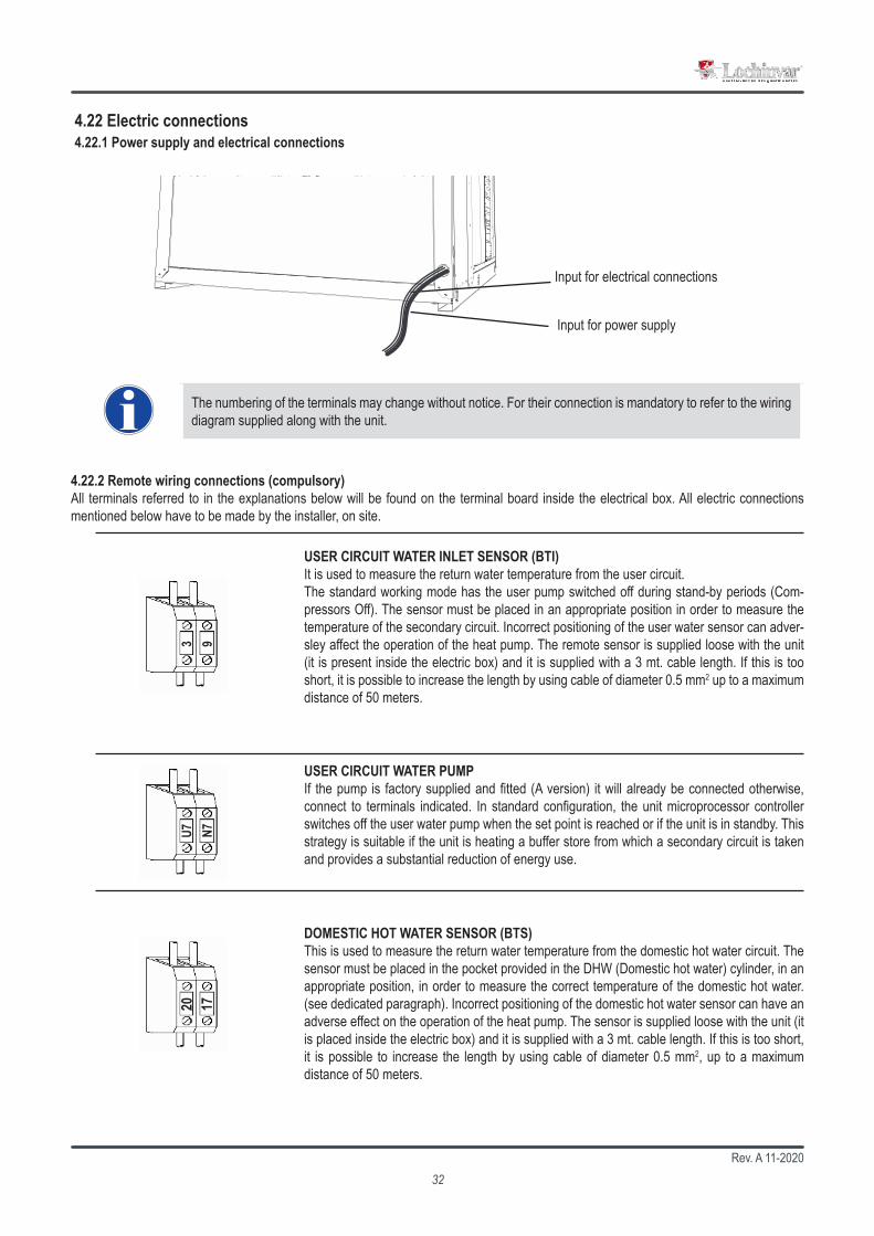
USER CIRCUIT WATER INLET SENSOR (BTI) It is used to measure the return water temperature from the user circuit. The standard working mode has the user pump switched off during stand-by periods (Com-pressors Off). The sensor must be placed in an appropriate position in order to measure the temperature of the secondary circuit. Incorrect positioning of the user water sensor can adver-sley affect the operation of the heat pump. The remote sensor is supplied loose with the unit (it is present inside the electric box) and it is supplied with a 3 mt. cable length. If this is too short, it is possible to increase the length by using cable of diameter 0.5 mm2 up to a maximum distance of 50 meters.
4.22.2 Remote wiring connections (compulsory)All terminals referred to in the explanations below will be found on the terminal board inside the electrical box. All electric connections mentioned below have to be made by the installer, on site.
The numbering of the terminals may change without notice. For their connection is mandatory to refer to the wiring diagram supplied along with the unit.
4.22 Electric connections4.22.1 Power supply and electrical connections
Input for power supply
Input for electrical connections
USER CIRCUIT WATER PUMP If the pump is factory supplied and fitted (A version) it will already be connected otherwise, connect to terminals indicated. In standard configuration, the unit microprocessor controller switches off the user water pump when the set point is reached or if the unit is in standby. This strategy is suitable if the unit is heating a buffer store from which a secondary circuit is taken and provides a substantial reduction of energy use.
DOMESTIC HOT WATER SENSOR (BTS)This is used to measure the return water temperature from the domestic hot water circuit. The sensor must be placed in the pocket provided in the DHW (Domestic hot water) cylinder, in an appropriate position, in order to measure the correct temperature of the domestic hot water. (see dedicated paragraph). Incorrect positioning of the domestic hot water sensor can have an adverse effect on the operation of the heat pump. The sensor is supplied loose with the unit (it is placed inside the electric box) and it is supplied with a 3 mt. cable length. If this is too short, it is possible to increase the length by using cable of diameter 0.5 mm2, up to a maximum distance of 50 meters.
Rev. A 11-202033
6 9U8
68 69 2N1
N83 9
U7 N71 2
43 2643 41
65 2N1
62 2N1
43 4215
015
490 91 92
+ -VR
N
6 9U8
68 69 2N1
N83 9
U7 N71 2
43 2643 41
65 2N1
62 2N1
43 4215
015
490 91 92
+ -VR
N
1 243 26
43 4165 2N
162 2N
143 42
150
154
90 91 92
+ -VR
N
1 243 26
43 4165 2N
162 2N
143 42
150
154
90 91 92
+ -VR
N
1 243 26
43 4165 2N
162 2N
143 42
150
154
90 91 92
+ -VR
N
1 243 26
43 4165 2N
162 2N
143 42
150
154
90 91 92
+ -VR
N
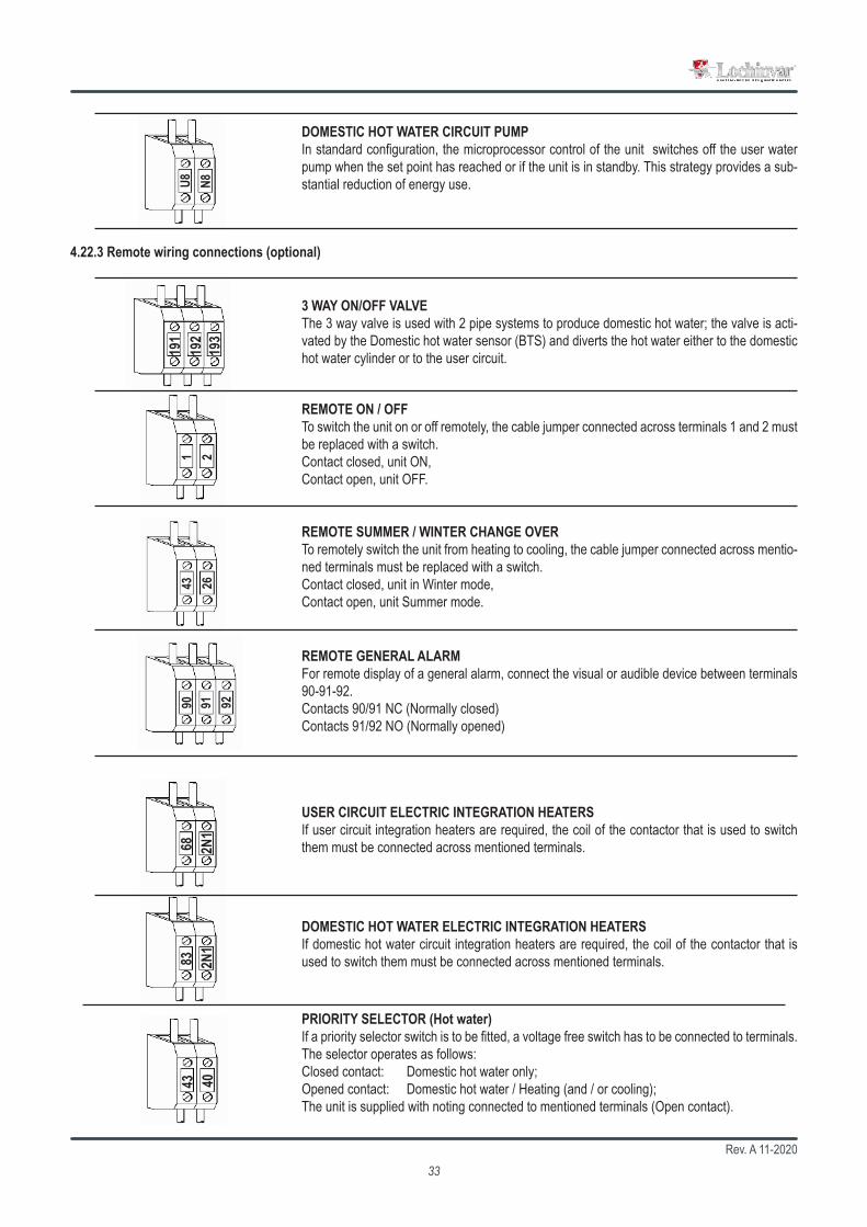
191
192
193
68 2N1
83 2N1
43 40
REMOTE ON / OFFTo switch the unit on or off remotely, the cable jumper connected across terminals 1 and 2 must be replaced with a switch.Contact closed, unit ON,Contact open, unit OFF.
4.22.3 Remote wiring connections (optional)
REMOTE GENERAL ALARMFor remote display of a general alarm, connect the visual or audible device between terminals 90-91-92.Contacts 90/91 NC (Normally closed)Contacts 91/92 NO (Normally opened)
USER CIRCUIT ELECTRIC INTEGRATION HEATERSIf user circuit integration heaters are required, the coil of the contactor that is used to switch them must be connected across mentioned terminals.
DOMESTIC HOT WATER ELECTRIC INTEGRATION HEATERSIf domestic hot water circuit integration heaters are required, the coil of the contactor that is used to switch them must be connected across mentioned terminals.
DOMESTIC HOT WATER CIRCUIT PUMPIn standard configuration, the microprocessor control of the unit switches off the user water pump when the set point has reached or if the unit is in standby. This strategy provides a sub-stantial reduction of energy use.
3 WAY ON/OFF VALVEThe 3 way valve is used with 2 pipe systems to produce domestic hot water; the valve is acti-vated by the Domestic hot water sensor (BTS) and diverts the hot water either to the domestic hot water cylinder or to the user circuit.
REMOTE SUMMER / WINTER CHANGE OVERTo remotely switch the unit from heating to cooling, the cable jumper connected across mentio-ned terminals must be replaced with a switch.Contact closed, unit in Winter mode,Contact open, unit Summer mode.
PRIORITY SELECTOR (Hot water)If a priority selector switch is to be fitted, a voltage free switch has to be connected to terminals. The selector operates as follows:Closed contact: Domestic hot water only;Opened contact: Domestic hot water / Heating (and / or cooling);The unit is supplied with noting connected to mentioned terminals (Open contact).

Rev. A 11-202034
44 455 9
8 943 35
1 243 26
43 4165 2N
162 2N
143 42
150
154
90 91 92
+ -VR
N
44 455 9
8 943 35
44 455 9
8 943 35
6L2
6L1
2018
4.22.4 Factory fitted wiring connections
WEATHER COMPENSATED SENSOR (BTE)This is used to measure the ambient temperature enabling weather compensation modulation of the user set point with respect to the ambient conditions.
USER CIRCUIT WATER OUTLET SENSOR (BTO)This is used to measure the outlet user temperature; it is also used as antifreeze protection in cooling mode; it is connected to the terminals 5 and 9.
HEATING CABLE This is used to prevent freezing of the condensate produced, in the outlet of the drain tray. The maximum current must not excced 0.5 A relating to a maximum power of 100 W. The heating cable is operated in conjunction with the electric heater in the condensate drain tray.
USER CIRCUIT FLOW SWITCH (SFW1)This is used to protect the unit if there is a low water flow rate in the user circuit. It is factory fitted across mentioned terminals.
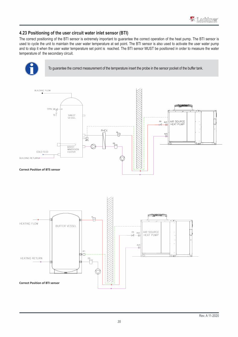
Rev. A 11-202035
To guarantee the correct measurement of the temperature insert the probe in the sensor pocket of the buffer tank.
4.23 Positioning of the user circuit water inlet sensor (BTI)The correct positioning of the BTI sensor is extremely important to guarantee the correct operation of the heat pump. The BTI sensor is used to cycle the unit to maintain the user water temperature at set point. The BTI sensor is also used to activate the user water pump and to stop it when the user water temperature set point is reached. The BTI sensor MUST be positioned in order to measure the water temperature of the secondary circuit.
7 Lombard Way Telephone - +44(0)1295 269981The MXL Centre Fax - +44(0)1295 271640Banbury E Mail - [email protected] 4TJ Internet - www.lochinvar.ltd.uk
Lochinvar Ltd reserves the right to change specifications without prior notice.
All necessary additional valves and fittings to be determined by those otherthan Lochinvar Ltd.
Lochinvar Limited may provide technical advice and guidance to assist withbest practice, optimisation and installation of Lochinvar products; however, wewill not be liable for any duties as Designers under Construction (Design andManagement Regulations 2015). In all cases where information is provided,the customer must assess and manage risks associated with the technicalinformation and advice provided.
Description :
REV
DRAWING NO.
SHEET SIZE SCALE
DRAWN CHKD DATE DETAIL
1
1 x ASHP Providing DHW
SH SA 22/01/21
A3 NTS
Lochinvar LtdEV EXPANSION VALVEEXV EXPANSION VESSELAVM ANTI VIBRATION MOUNTIV ISOLATION VALVENRV NON RETURN VALVEAS AIR SEPARATORDS DIRT SEPARATORPMP PUMPAV AIR VENTFR FLOW REGULATOR/COMMISSIONING SETAVC ANTI VIBRATION COUPLINGTS1/TS2 ASHP TEMP SENSORSBTS TANK TEMP SENSORHL HIGH LIMIT STATFSW FLOW SWITCHTPRV TEMP AND PRESSURE RELIEF VALVETD TUNDISHSTR IN-LINE STRAINER (INLET SIDE)DV DRAIN VALVEPRV PRESSURE REDUCING VALVETP TEMP/PRESSURE GAUGEDCV DOUBLE CHECK VALVE3PV THREE PORT VALVE
7 Lombard Way Telephone - +44(0)1295 269981The MXL Centre Fax - +44(0)1295 271640Banbury E Mail - [email protected] 4TJ Internet - www.lochinvar.ltd.uk
Lochinvar Ltd reserves the right to change specifications without prior notice.
All necessary additional valves and fittings to be determined by those otherthan Lochinvar Ltd.
Lochinvar Limited may provide technical advice and guidance to assist withbest practice, optimisation and installation of Lochinvar products; however, wewill not be liable for any duties as Designers under Construction (Design andManagement Regulations 2015). In all cases where information is provided,the customer must assess and manage risks associated with the technicalinformation and advice provided.
Description :
REV
DRAWING NO.
SHEET SIZE SCALE
DRAWN CHKD DATE DETAIL
1
1 x ASHP working with a buffer provding heating
SH SA 22/01/21
A3 NTS
Lochinvar LtdEV EXPANSION VALVEEXV EXPANSION VESSELAVM ANTI VIBRATION MOUNTIV ISOLATION VALVENRV NON RETURN VALVEAS AIR SEPARATORDS DIRT SEPARATORPMP PUMPAV AIR VENTFR FLOW REGULATOR/COMMISSIONING SETAVC ANTI VIBRATION COUPLINGTS1/TS2 ASHP TEMP SENSORSBTS TANK TEMP SENSORHL HIGH LIMIT STATFSW FLOW SWITCHTPRV TEMP AND PRESSURE RELIEF VALVETD TUNDISHSTR IN-LINE STRAINER (INLET SIDE)DV DRAIN VALVEPRV PRESSURE REDUCING VALVETP TEMP/PRESSURE GAUGEDCV DOUBLE CHECK VALVE3PV THREE PORT VALVE
Correct Position of BTS sensor
Correct Position of BTI sensor

Rev. A 11-202036
CH
FL
1
VRBTIBTO
UT
MC
ECOIVVR
NONC
VRV
YEC
YEC
VR
MC
SV
EXV 1
EXV 2
CHR1
EXV 4
SFW
LR
M
M
MFAMFC
SO
BTI MFCBTO SFWCH SO
CHR SVECO UTEXV VRFL VRVIV YECLRMCMFA
Models 252-752
4.24 Refrigerant circuit layout
P2U VersionThis is a two pipe version that can produce hot water for heating and cold water for cooling. The unit is used with two pipe water based change-over systems. It is not able to produce domestic hot water.
P2S VersionThis is a two pipe version that can, in addition to producing hot water for heating and cold water for cooling, also generate domestic hot water. The controller has dual heating set points (heating and DHW) and can also control a three port diverting valve that directs the DHW to the cylinder. DHW production has priority irrespective of the mode of operation of the unit. The unit is normally used with two pipe water based change-over systems.
4.24.1 Refrigerant circuit layout version P2U - P2S - single finned coil
User water input probe Centrifugal fanUser water output probe User flow switchCharging plug Source sideCharging plug Shut off valveEconomizer User sideTermostatic valve Check valveLiquid line filter Reverse cycle valveMoisture indicator sight glass By-pass solenoid valveLiquid receiver Refrigeration connectionsCompressor Hydraulic connectionsSource fan
The cooling circuit principle diagram is purely indicative.

Rev. A 11-202037
CH
FL
1
VRBTIBTO
UT
MC
ECOIVVR
NONC
VRV
YEC
YEC
VR
MC
SV
EXV 1 SO
M
M
MFAMFC
EXV 2
EXV 3
CHR1
EXV 4
SFW
LR
VR
BTI MFCBTO SFWCH SO
CHR SVECO UTEXV VRFL VRVIV YECLRMCMFA
Models 852-12024.24.2 Refrigerant circuit layout version P2U - P2S - two finned coils
P2U VersionThis is a two pipe version that can produce hot water for heating and cold water for cooling. The unit is used with two pipe water based change-over systems. It is not able to produce domestic hot water.
P2S VersionThis is a two pipe version that can, in addition to producing hot water for heating and cold water for cooling, also generate domestic hot water. The controller has dual heating set points (heating and DHW) and can also control a three port diverting valve that directs the DHW to the cylinder. DHW production has priority irrespective of the mode of operation of the unit. The unit is normally used with two pipe water based change-over systems.
User water input probe Centrifugal fanUser water output probe User flow switchCharging plug Source sideCharging plug Shut off valveEconomizer User sideTermostatic valve Check valveLiquid line filter Reverse cycle valveMoisture indicator sight glass By-pass solenoid valveLiquid receiver Refrigeration connectionsCompressor Hidraulic connectionsSource fan
The cooling circuit principle diagram is purely indicative.
Rev. A 11-202038
5. UNIT START UP5.1 Preliminary checks
Start-up operations must be performed in accordance with the instructions detailed in the previous paragraphs.
If it is required to switch the unit on and off, never do this using the main isolator: this should only be used to discon-nect the unit from the power supply when the unit is to be permanently off. Isolation will result in no supply for the crankcase heater and on start up the compressor could be seriously damaged.
Do not modify internal wiring of the unit as this will immediately invalidate the warranty.
Crankcase heaters must be powered at least 12 hours before start up (pre-heating period) To do this, isolate the compressor(s), fans and pump(s) in the electrics box and then switch on the main isolator (heaters are automatically supplied when the main switch is closed). The crankcase heaters are working properly if, after several minutes, the compressor crankcase temperature is about 10÷15°C higher than ambient temperature.
During the 12 hours pre-heating period it is also important to check that the label OFF is shown on the display or that the unit is on stand-by mode. If there is an accidental start-up before the 12 hours pre-heating period has elapsed, the compressors could be seriously damaged and therefore the warranty will immediately terminate .
• Verify that the unit is installed in a workmanlike manner and in accordance with the guidelines in this manual.• Check that all power cables are properly connected and all terminals are correctly fixed.• The operating voltage between phases R S T is the one shown on the unit labels.• Check that the unit is connected to the system earth.• Check that there is no refrigerant leakage.• Check for oil stains, sign of a possible leak.• Check that the refrigerant circuit shows the correct standing pressure on the pressure gauges (if present) otherwise use external ones.• Check that the Shrader port caps are the correct type and are tightly closed. • Check that crankcase heaters are powered correctly (if present).• Check that all water connections are properly installed and all indications on unit labels are observed.• The system must be flushed, filled and vented in order to eliminate any air.• Check that the water temperatures are within the operation limits reported in the manual.• Before start up check that all panels are replaced in the proper position and locked with fastening screws.
Before starting the unit the checks detailed in this manual of the electric supply and connections, the hydraulic system and the refrigerant circuit, should be performed.
5.1.1 Before start-up
Damage can occur during shipment or installation. It is recommended that a detailed check is made, before the installation of the unit, for possible refrigerant leakages caused by breakage of capillaries, pressure switch con-nections, tampering of the refrigerant pipework, vibration during transport or general abuse suffered by the unit.

Rev. A 11-202039
°C 35 2 -----
°C 50 2 -----
°C 23 2 -----
°C 4,5 4
Bar 45 7
Bar 5,7 1,3
Bar 6,0
If the unit is required for heating/cooling only (without domestic hot water production) the internal parameter of the micropro-cessor FS1 has to be modified from 2 to 1 in order to avoid configuration alarms. Please contact the company for support.
5.1.2 Device Set-point Differential Reset
Device Set-point Differential Reset
Heating mode
Domestic hot water mode
Cooling mode
Anti-freeze thermostat MANUAL
High pressure switch Automatic for 3 times (than
manual)Low pressure switch
Water safety valve (Present in A versions only) Automatic
5.1.3 Controls during unit operation
• Check the rotation of the compressors and fans. If the rotation is incorrect, disconnect the main switch and change over any two phases of the incoming main supply to reverse motor rotation (only for units with three-phase fan motors).
• After several hours of operation, check that the sight glass has a green colour core: if the core is yellow moisture is present in the circuit. In this event it is necessary for dehydration of the circuit to take place. This must be performed by qualified people only. Check that there are no continuous vapour bubbles present at the sight glass. This would indicate a shortage of refrigerant. A few vapour bubbles are acceptable.
• Few minutes after start up, check that the equivalent temperature of the refrigerant gas, measured at the pressure inside the finned coil with fans running at full speed, differs from the outside air temperature of about 7-10°C; also verify that the equivalent temperature of the refrigerant gas, measured at the pressure in the plate heat exchanger, differs from the temperature of the water outlet from the exchanger of about 3-5°C .

Rev. A 11-202040
T1 T2 T3 T4 T5 T6 T7 T8
00:00 01/01/2014
30.035.0 5.050.0
°C°C°C
°C
PROBES SET ALARM SERVICE CIRC.
5.2 Position of the control panel
Control panel
Unit ON: HeatingUnit ON: Heating
Evaporator inlet temperatureEvaporator outlet temperatureExternal air temp. (FC)San. water temperature
5.2.1 Display icons
Icon Meaning Icon Meaning
Number of compressors in operation. Indicates that the electric heaters are active.
Water pump Economy or ON/OFF by timetable.
Indicates that the fans are working. Free cooling is active (not available).
Indicates that an alarm is active. Domestic hot water.
Economy function Indicates that the defrost is active.
Unloading function (not available).

Rev. A 11-202041
T1 T2 T3 T4 T5 T6 T7 T8
00:00 01/01/2014
30.035.0 5.050.0
°C°C°C
°C
PROBES SET ALARM SERVICE CIRC.
T2: PROBES
SET
ALARM
SERVICE
CIRC
EXIT
T3:
PROBES
SET
ALARM
SERVICE
CIRC
EXIT
T4:
PROBES
SET
ALARM
SERVICE
CIRC
EXIT
T5:
PROBES
SET
ALARM
SERVICE
CIRC
EXIT
T6:
PROBES
SET
ALARM
SERVICE
CIRC
EXIT
T7:
PROBES
SET
ALARM
SERVICE
CIRC
EXIT
T8:
PROBES
SET
ALARM
SERVICE
CIRC
EXIT
Rosso / RedNero / BlackBianco / White
ENTER
Nero / BlackBianco / WhiteRosso / Red
Allows to read the value of the probes configured
Allows to switch on the unit in cooling mode
Allows to read and modify the set point
Allows to read and reset the alarms
Allows to switch on the unit in heating mode
Allows to enter the SERVICE menù
Allows to read the main information of the circuits (compressor status, water pump status, pressure probe value,…)
When the unit is turned on, the display will be as follows:
Stand-byStand-by
Evaporator inlet temperatureEvaporator outlet temperatureExternal air temp. (FC)San. water temperature
5.2.2 Key function
5.3 How to remote the control5.3.2 Remote keyboard connection (VGI890)
Special care must be taken when connecting the keyboard to the Ichill200D, to avoid irreparable damage to the controller or/and keyboard
• In case of power supply failure (wire black or red), the keyboard doesn’t work.• In case of comunication problems, the display shows “noL” message.
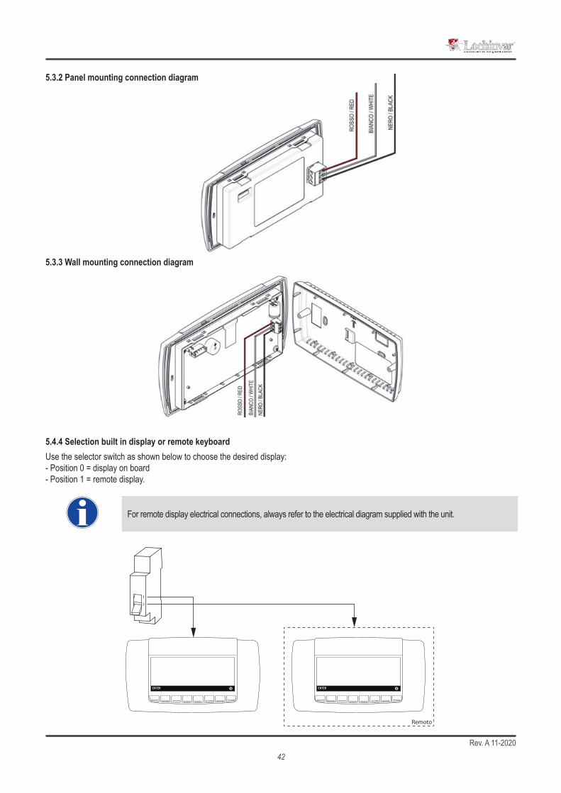
Rev. A 11-202042
ENTER ENTER
Remoto
5.3.2 Panel mounting connection diagram
5.3.3 Wall mounting connection diagram
5.4.4 Selection built in display or remote keyboard
For remote display electrical connections, always refer to the electrical diagram supplied with the unit.
Use the selector switch as shown below to choose the desired display:- Position 0 = display on board- Position 1 = remote display.

Rev. A 11-202043
6.1.1 Switch the unit on from the keyboard
Heating modeTo start the unit in heating mode, press the
PROBES
SET
ALARM
SERVICE
CIRC
EXIT
key. The icon appears on the display. If requested, the compressor safety delay countdown starts and the compressor icon flashes. The water pump will be activated after few seconds and then, once the compressor countdown has finished, the compressor starts and the icon remains on. The display shows the user water inlet temperature and Domestic hot water inlet temperature.
Domestic hot water modeAt the first start up, the unit microprocessor control checks the domestic hot water inlet temperature measured by the sensor BTS (this has priority over the other parameters) and, if the measured temperature is lower than the domestic hot water set point , it will activate the domestic hot water mode automatically. If the unit is required to operate in heating and the domestic hot water temperature is higher than the set point (there is no requirement for domestic hot water) the microprocessor control will activate the unit in heating mode. If the unit is required to operate in cooling and domestic hot water mode the microprocessor control will activate both functions at the same time. If domestic hot water is not required, the microprocessor control will activate cooling mode only.
In stand-by mode, the controller gives the possibility to:• display the set values• manage alarms, theyr display and reports.
6.1 Switch the unit onUnit switch-on and switch-off can take place:• From the keyboard• From digital input configured as remote ON/OFF
6. USE
If it is required to switch the unit on and off, never do this using the main isolator: this should only be used to discon-nect the unit from the power supply when the unit is to be permanently off. Isolation will result in no supply for the crankcase heater and on start up the compressor could be seriously damaged.
Before first start-up, consult and carry out the operations described in the paragraph “ Periodical checks “.
5.3.1 Selection built in display or remote keyboard

Rev. A 11-202044
T1 T2 T3 T4 T5 T6 T7 T8T1 T2 T3 T4 T5 T6 T7 T8
00:00 01/01/2014
20.263.630.644.9
°C°C°C
°C
PROBES SET ALARM SERVICE CIRC.
00:00 01/01/2014
28.427.031.8N.C.
°C°C°C
PROBES SET ALARM SERVICE CIRC.
T1 T2 T3 T4 T5 T6 T7 T8T1 T2 T3 T4 T5 T6 T7 T8
00:00 01/01/2014
20.263.630.644.9
°C°C°C
°C
PROBES SET ALARM SERVICE CIRC.
00:00 01/01/2014
28.427.031.8N.C.
°C°C°C
PROBES SET ALARM SERVICE CIRC.
T1 T2 T3 T4 T5 T6 T7 T8
00:00 01/01/2014
20.233.130.644.9
°C°C°C
°C
PROBES SET ALARM SERVICE CIRC.
6.2 StopTo switch the unit off press the key .
HEATING MODE COOLING MODE
Unit ON: Heating Unit ON: Heating
Evaporator inlet temperatureEvaporator outlet temperatureExternal air temp. (FC)San. water temperature
Unit ON: Cooling Unit ON: Cooling
Evaporator inlet temperatureEvaporator outlet temperatureExternal air temp. (FC)San. water temperature
6.1.3 Switch the unit on from from digital inputIf the unit is switch off by remote digital input, the display shows:
When the digital input is not active, the unit is in OFF mode
• The remote input has the priority with respect to the keyboard• The unit can only be switched-on and off if the remote input is activated
Remote OFFRemote OFF
Evaporator inlet temperatureEvaporator outlet temperatureExternal air temp. (FC)San. water temperature
Unit ON: Heating Unit ON: Heating
Evaporator inlet temperatureEvaporator outlet temperatureExternal air temp. (FC)San. water temperature
6.1.2 Heating and cooling modeThe display shows the typical visualization during the unit working in:

Rev. A 11-202045
T1 T2 T3 T4 T5 T6 T7 T8
35.0
50.0 °C
°C
T1 T2 T3 T4 T5 T6 T7 T8
00:00 01/01/2014
30.0
OFF
OFF35.0 5.050.0
°C°C°C
°C
PROBES SET SET EXITALARM ALARMSERVICE CIRC.
10÷55°C 35°C
20÷55°C 50°C
10÷25°C 23°C
0÷15°C 10°C
The units are supplied with a very sophisticated control system with many other parameters that are not adjustable by the end user; these parameters are protected by a manufacturer password.
6.3.1 Adjustable parameters
The adjustable set point that can be modified by the end user are:
Function Adjustment limit Default value
Heating set-point
Domestic hot water set-point
Cooling set-point
Set point compensation
Password (Contact the company)
6.3 Set pointTo change the set-point from the main screen, press SET.
To modify the values, move the cursor with T1; press SET to select, the value starts blinking, change the data pressing T1 and T2. Once the required value is reached, press again SET to confirm.The cursor will automatically position itself on the next value, to modify it, repeat the operation just described.In this screen it is also possible to verify (but not modify) whether the energy saving mode and dynamic set are active.
Press EXIT to go back to the main menu.
All set points refer to the return temperature from the plant. In case hot water at 45°C is requested and the ∆t is 5°C, then the set point must be set at 40°C. In case the ∆t is 8°C, then the set point must be set at 37°C. In case cold water is requested, for example at 15°C and the ∆t is 5°C, then the set point must be set at 20°C. If the ∆t is 8°C, then the set point must be set at 23°C.
Stand-byStand-by
Evaporator inlet temperatureEvaporator outlet temperatureExternal air temp. (FC)San. water temperature
Set point Set point
Heating
Sanitary water
Energy saving
Dynamic set

Rev. A 11-202046
T1 T2 T3 T4 T5 T6 T7 T8
00:00 01/01/2014
30.035.0 5.050.0
°C°C°C
°C
PROBES SET ALARM SERVICE CIRC.
T1 T2 T3 T4 T5 T6 T7 T8
28.026.618.831.2
°C°Cbar
°C
EXITALARM
T1 T2 T3 T4 T5 T6 T7 T8
27.049.723.3
°C°C°C
EXITALARM
T1 T2 T3 T4 T5 T6 T7 T8T1 T2 T3 T4 T5 T6 T7 T8
00:00 01/01/2014
30.035.0 5.050.0
°C°C°C
°C
PROBES SET EXITALARM RST ALL RESETSERVICE CIRC.
AttivoActiveAktiv
6.4 PROBES keyTo view all the parameters measured by the sensors of the unit press PROBES;
By pressing the T5 key, all relevant values of the circuit will be displayed
Press
PROBES
SET
ALARM
SERVICE
CIRC
EXIT to go back to the main menu.
Stand-byStand-by
Evaporator inlet temperatureEvaporator outlet temperatureExternal air temp. (FC)San. water temperature
Probes visualizationProbes visualization
San. water temperatureSan. water secur. temper.External air temperature
Probes visualizationProbes visualization
Evaporator inlet temperatureEvaporator outlet temperatureCondenser press./temp.circ.1Combined def. temp.circ.1
6.5 ALARM key
When the alarm occurs, the display shows the icon blinking.Press ALARM key to read the alarm status:
Unit ON: HeatingUnit ON: Heating
Evaporator inlet temperatureEvaporator outlet temperatureExternal air temp. (FC)San. water temperature
AlarmsAlarmsb1HPb1HP
High pressure circuit 1 (pressostat)

Rev. A 11-202047
T1 T2 T3 T4 T5 T6 T7 T8
00:00 01/01/2014
28.427.031.8N.C.
°C°C°C
PROBES SET ALARM SERVICE CIRC.
T1 T2 T3 T4 T5 T6 T7 T8T1 T2 T3 T4 T5 T6 T7 T8
ALARM ENTER EXITALARM ENTER EXIT
6.6 CIRC key
Pressing CIRC can view the different parameters of the unit:
Pressing T4 and T5 you move from one screen to another while with T1 and T2 you scroll through the menu items. Press ENTER key to view the values.
State of the compressors; the display shows compressors present in each circuit and the activation status of each one.Color black: compressor runningColor white: compressor on standby
In case of use of compressors in part-loading (typically screw compressors) an icon appears to the right of the compressor showing the level of step control.In case of use of On/Off compressors (Scroll) no icon appear to the right of the compressor.
Unit ON: HeatingUnit ON: Heating
Evaporator inlet temperatureEvaporator outlet temperatureExternal air temp. (FC)San. water temperature
Circuits statusCircuits status
Compressors status Unloading status Evaporating-condensing probe Evaporating pump status
Circuits statusCircuits status Condenser fan
The alarm status can be:• Reset: the alarm is not active and it is possible to reset it. Press T1 and T2 keys to select the alarm to select it and press RESET key to reset the alarm.• Password: in this case the alarm is no longer active, but you need a password to reset it (please contact the Company).• Active: the alarm is still active and it is not possible to reset it.
In case more resettable alarms are present, it’s possible to reset all of them at once pressing RST/ALL key.In any case, even if all the alarms are reset, they remain present in the alarm history (par. 6.7.7).

Rev. A 11-202048
T1 T2 T3 T4 T5 T6 T7 T8
ALARM EXIT
51 %
T1 T2 T3 T4 T5 T6 T7 T8
ALARM EXIT
T1 T2 T3 T4 T5 T6 T7 T8
ALARM EXIT
0 % 0 %
T1 T2 T3 T4 T5 T6 T7 T8
ALARM EXIT
255 %
T1 T2 T3 T4 T5 T6 T7 T8
ALARM EXIT
Compressor status
Evaporating-condensing probe
Compressor statusCompressor statusCircuit 1Circuit 1
Circuit 2Circuit 2 notconfigured
Evaporating-condensing probeEvaporating-condensing probe
CircuitCircuit 1 1 36.2 bar N.C.
Circuit Circuit 2 2 notconfigured
Unloading statusUnloading statusCircuit 1Circuit 1
unloading not ongoing
Circuit 2Circuit 2
notconfigured
Unloading status
Evaporator pump status
High press. Low press. High press. Low press.
Evaporator pump statusEvaporator pump status Evap. pump 1 Evap. pump 1 Evap. pump 2Evap. pump 2
notconfigured
Condenser fan
Condenser fanCondenser fan
Cond.Cond. fan 1 fan 1 Cond.Cond. fan fan 22

Rev. A 11-202049
T1 T2 T3 T4 T5 T6 T7 T8T1 T2 T3 T4 T5 T6 T7 T8
ENTER EXITENTER EXIT
6.7 SERVICE key
Press the SERVICE key to access the following menus:
Setting parameters (for service only) Electrical heater and pump down valve status
Time and date setting I/O status (Inputs and Outputs)
Compressors status Screw compressor information (Not configured)
Pumps Auxiliary outputs
Circuit maintenance Domestic hot water (if available)
Display of alarms Free cooling and Solar panel visualization (if available)
Alarm history Upload and download parameter map with Hot Key
Defrost (if available) Control panel
Press T4 key to display all the menu available.To modify and set the parameters move the cursor using the T1 and T2,press ENTER, to select the required menu, and then SET to select the desired value.Change the parameters by pressing the T1 and T2, and then press SET again to confirm.Press the
PROBES
SET
ALARM
SERVICE
CIRC
EXIT key to return to the main menu.

Rev. A 11-202050
T1 T2 T3 T4 T5 T6 T7 T8T1 T2 T3 T4 T5 T6 T7 T8
ALARM Pr2 Pr3
0
SET EXITENTER EXIT
T1 T2 T3 T4 T5 T6 T7 T8
ALARM Pr2 Pr3
0
ENTER EXIT
To enter service menu select moving between the icons with T1 and T2 keys and press ENTER.
The system prompts you to enter the password to access to different levels of security.
The first level allow to modify some parameters as for example heating and cooling set points and dynamic set points. Press SET key, with T1 modify the password to 1 then press SET again to confirm. The display show:
Press T1 and T2 to scroll through different groups of parameters. With password level 1 you could only change the Set Point (St), dynamic Set point (Sd), parameters of sanitary circuit (FS) and parameters for setting the time bands (ES); the unit must be switched on. Press EN-TER to enter in the group of parameters. Other parameters can only be modified by service with a dedicated password. Other parameters could be modified by service people only with a dedicated password.
1st level password (Pr1)1st level password (Pr1)
1st level password (Pr1)1st level password (Pr1)
Password OK! Press ENTER to continue
6.7.1 Service parameters setting
Code Meaning Code Meaning
St Set point US Auxiliary output
dP Main visualization FA Fan
CF Configuration Ar Antifreeze
Sd Dynamic set dF Defrost
ES Energy saving FS Sanitary water
Cr Compressor racks AL Alarms
CO Compressor
Parameters list:

Rev. A 11-202051
T1 T2 T3 T4 T5
dP
CF
Sd
ES
Cr
CO
US
FAPr1
Ar
dF
FS
AL
PSW
T6 T7 T8
St
ALARM ENTER EXIT
T1 T2 T3 T4 T5
St04St03St02St01
40.015.05.010.0
°C°C°C°C
T6 T7 T8
ALARM SET EXIT
T1 T2 T3 T4 T5
dP
CF
Sd
ES
Cr
CO
US
FAPr1
Ar
dF
FS
AL
PSW
T6 T7 T8
St
ALARM ENTER EXIT
T1 T2 T3 T4 T5
Sd04Sd03Sd02Sd01
20.00.010.00.0
°C°C°C°C
T6 T7 T8
ALARM SET EXIT
T1 T2 T3 T4 T5
Pr1Sd06Sd05
0-25.00.0
°C°C
T6 T7 T8
ALARM SET EXIT
Set pointSet point
To modify the value of the parameter: press T1 or T2 to select the parameter to modify then press SET the value start to blinking, press T1 and T2 to modify, than press SET again to confirm.The values available in the group of parameters “Set point” (St) are: summer set point (St01), winter set point (St04), summer regolation band (St07) and winter regolation band (St08).
The values available in the group of parameters “Dynamic set point” (Sd) are: dynamic set point: summer offset (Sd01), dynamic set point: winter offset (Sd02), dynamic set point: summer outside temp. (Sd03), dynamic set point: winter outside temp. (Sd04), dynamic set point: summer differential temp. (Sd05) and dynamic set point: winter differential temp.(Sd06).For more informations about the parameters see par. 6.3.1 and 6.3.2.
Parameter group selectionParameter group selection
Parameter group selectionParameter group selection
Dynamic set pointDynamic set point
Summer set pointSummer set point
Dynamicsetpoint:summeroffsetDynamicsetpoint:summeroffset
Dynamicsetpoint:summerdifferentialtemp.Dynamicsetpoint:summerdifferentialtemp.

Rev. A 11-202052
(Sd06) (Sd04)
(St04)
(Sd02)
106
7
8
9
10
11
12
13
15 20 25 30 35 40 45
(Sd05) (Sd03)
(St04)
(Sd01)
Set p
oint c
ompe
nsati
on (°
C)
Ambient temperature (°C)
Weather compensated functionThis function makes it possible to activate the weather compensation sensor in order to optimize the efficiency of the unit. Automatically it modifies the set-point value with respect to external air temperature: a calculation is performed on the set-point to provide a revised value of set point for higher ambient conditions (see example given below). This function makes it possible to save energy and to operate the unit in severe ambient conditions. This function is only active in heating mode.
All units are factory set with the weather compensated function activated. The slope starts at +20°C with a differential of 10°C.
With the energy saving mode activated, if the SET key is pressed twice the bottom of the display shows the SEtTR (weather compensated set point) label that is the specific set point calculated by the microprocessor control for the measured ambient temperature condition.
Set p
oint c
ompe
nsati
on (°
C)
Ambient temperature (°C)
Heating mode
Cooling mode

Rev. A 11-202053
T1 T2 T3 T4 T5
dP
CF
Sd
ES
Cr
CO
US
FAPr1
Ar
dF
FS
AL
PSW
T6 T7 T8
St
ALARM ENTER EXIT
T1 T2 T3 T4 T5
Pr1FS04FS03FS02
04.045.01
°C°C
T6 T7 T8
ALARM SET EXIT
The values available in the group of parameters “Sanitary circuit” (FS) are: Sanitary water priority (FS02), Sanitary water set point (FS03), Sanitary water proportional band (FS04) .
Parameter group selectionParameter group selection
Sanitary water prioritySanitary water prioritySanitary circuitSanitary circuit
6.7.2 Time bands settingTo access the group of parameters for setting the time bands, select ES
ES01 Start of operation range N°1 (0÷24) ES17 Energy saving differential in heat pump operation
ES02 End of operation range N°1 (0÷24) ES18 Maximum operating time of the unit in OFF by RTC if the unit is forced into ON by key.
ES03 IStart of operation range N°2 (0÷24) ES19 Time band 1 Domestic hot water: startES04 End of operation range N°2 (0÷24) ES20 Time band 1 Domestic hot water: endES05 Start of operation range N°3 (0÷24) ES21 Time band 2 Domestic hot water: startES06 End of operation range N°3 (0÷24) ES22 Time band 2 Domestic hot water: end
ES07 Monday with time band in energy savingMonday operation with automatic on/off switch ES23 Time band 3 Domestic hot water: start
ES08 Tuesday with time band in energy savingTuesday operation with automatic on/off switch ES24 Time band 3 Domestic hot water: end
ES09 Wednesday with time band in energy savingWednesday operation with automatic on/off switch ES25 Monday: time band selection
ES10 Thursday with time band in energy savingThursday operation with automatic on/off switch ES26 Tuesday: time band selection
ES11 Friday with time band in energy savingFriday operation with automatic on/off switch ES27 Wednesday: time band selection
ES12 Saturday with time band in energy savingSaturday operation with automatic on/off switch ES28 Thursday: time band selection
ES13 Sunday with time band in energy savingSunday operation with automatic on/off switch ES29 Friday: time band selection
ES14 Increased energy saving set in chiller operation ES30 Saturday: time band selectionES15 Energy saving differential in chiller operation ES31 Sunday: time band selectionES16 Increasing set energy saving in heat pump operation ES32 Energy saving: domestic hot water set point offset

Rev. A 11-202054
T1 T2 T3 T4 T5 T6 T7 T8
ALARM EXITSET
T1 T2 T3 T4 T5
dP
CF
Sd
ES
Cr
CO
US
FAPr1
Ar
dF
FS
AL
PSW
T6 T7 T8
St
ALARM ENTER EXIT
ES01 18:00ES01 18:00ES02 00:00ES02 00:00ES03 05:00ES03 05:00
Operating modesThe possible operating modes are:
• Automatic ON-OFF: automatic switching on and off of the unit according to set times.• Energy Saving: Allows you to set two different set points, for example one for the day and one for the night.
Up to three time bands can be set. Select the time to be changed by moving with T1 and T2 keys confirm the parameter select with ENTER key than change the values with T1 and T2 keys.Press T5 key to view all available parameters.
Time band n°1Time band n°1 Time band n°2 Time band n°2 Time band n°3 Time band n°3
Parameter group selectionParameter group selection
Energy SavingEnergy Saving
The combinations of time bands that can be set on different days of the week are:0 = none1 = Time band 12 = Time band 23 = Time band 1 and 24 = Time band 35 = Time band 1 and 36 = Time band 2 and 37 = All time bands

Rev. A 11-202055
T1 T2 T3 T4 T5 T6 T7 T8
ALARM EXIT
T1 T2 T3 T4 T5 T6 T7 T8
SETALARM EXIT
10 : 0705 / 7 / 14
T1 T2 T3 T4 T5 T6 T7 T8
ALARM EXIT
T1 T2 T3 T4 T5 T6 T7 T8
ALARM EXIT
18:00 00:0018:00 00:0005:00 19:0005:00 19:0000:00 08:0000:00 08:00
6.7.2 Setting date and time
To enter this menu select moving between the icons with the keys T1 and T2 and press ENTER.
Press T1 and T2 to select the value you want to edit than press SET. The selected parameter will start blinking, press T1 and T2 to set the value and than press SET to confirm.Pressing T5 it is possible to read the information about the Energy saving, ON/OFF scheduling and time bands. To modify the hour of the time band and to enable the function is necessary to insert the password, in case you do not have a password, you can only view the different parameters..
Clock/timebandsconfigurationClock/timebandsconfiguration
Clock settingClock setting Data setting Data setting Dat of the week Tuesday Dat of the week Tuesday
Clock/timebandsconfigurationClock/timebandsconfiguration
Energy saving Disabled Energy saving Disabled ON/OFF scheduling ON/OFF scheduling DisabledDisabled
Clock/timebandsconfigurationClock/timebandsconfiguration
Time band n°1Time band n°1 Time band n°2 Time band n°2 Time band n°3 Time band n°3
Clock/timebandsconfigurationClock/timebandsconfiguration
MondayMonday Tuesday Tuesday Wednesday Wednesday
Start StopStart Stop Energy saving Auto ON-OFFEnergy saving Auto ON-OFFDisabledDisabled DisabledDisabledDisabled DisabledDisabled DisabledDisabled DisabledDisabled Disabled

Rev. A 11-202056
T1 T2 T3 T4 T5 T6 T7 T8
RESETALARM EXIT
19 RST0
T1 T2 T3 T4 T5 T6 T7 T8
ENB/DISALARM EXIT
T1 T2 T3 T4 T5 T6 T7 T8T1 T2 T3 T4 T5 T6 T7 T8
EXITENTER EXITALARM ENB/DISALARM
0 2 RST
Ore Reset
Circuito 1Circuito 1
Comp 1 abilitato 0 2 RSTComp 1 enabledComp 1
6.7.4 Water pumps
6.7.5 Circuit maintenance
Water pumpsWater pumps
Evaporator water pump
Sanitary water pump
Hour Reset
CircuitsCircuits
Circuit 1
Circuit 2
enabled
notconfigured
To enter this menu select moving between the icons with the keys T1 and T2 and press ENTER.It is possible to display the status of the circuits. The function ENB/DIS is only possible by service people.
6.7.3 Compressor maintenance
To enter this menu select moving between the icons with the keys T1 and T2 and press ENTER.It is possible to display the compressors working hour and the number of activations. Select the circuit with the keys T1 and T2 than press ENTER to display the parameters. The disabling function of the compressors ENB/DIS is only possible by service people.
Compressor mainteinanceCompressor mainteinance
Circuit 1
Circuit 2
Circuit 1Circuit 1Status Hour Start-up Reset
To enter this menu select moving between the icons with the keys T1 and T2 and press ENTER.It is possible to display the working hours of water pumps. The function RESET is only possible by service people.

Rev. A 11-202057
T1 T2 T3 T4 T5 T6 T7 T8
RESETRST ALL EXIT
T1 T2 T3 T4 T5 T6 T7 T8
RST ALLALARM EXIT
T1 T2 T3 T4 T5 T6 T7 T8
ENTERALARM EXIT
45 : 0
AttivoActive
6.7.6 Alarms
AlarmsAlarms b1HPb1HP Clock alarm
To enter this menu select moving between the icons with the keys T1 and T2 and press ENTER.
For the management of alarms see par. 6.5.
6.7.7 Alarm log
Alarm logAlarm log b1HP 001b1HP 001 High pressure circuit 1
b1AC 002b1AC 002 Antifreeze circuit 1 in summer mode
To enter this menu select moving between the icons with the keys T1 and T2 and press ENTER.Pressing T4 and T5 it is possible to read the last 99 alarms. The function of reset of all alarms RST ALL is only possible by service people.
6.7.8 Defrost
Defrost statusDefrost status Circuit 1Circuit 1 cycle not in progresscycle not in progress Time to start (mm:ss)
Circuit 2 Circuit 2 notconfigurednotconfigured
To enter this menu select moving between the icons with the keys T1 and T2 and press ENTER.For each circuit it is possible to read the status of the defrost and, after selecting the circuit, pressing the ENTER key it is possible to display some parameters relating to the defrosting of the circuit (values related to the probes and to the set points).
Aktiv

Rev. A 11-202058
T1 T2 T3 T4 T5 T6 T7 T8
ALARM EXIT
R1
R1
SV1
SV2
OFF
T1 T2 T3 T4 T5 T6 T7 T8
ENTERALARM EXIT
T1 T2 T3 T4 T5 T6 T7 T8
ALARM EXIT
36.2 barN.C.6.0 bar7.0 bar
T1 T2 T3 T4 T5 T6 T7 T8
ALARM EXIT
36.2 barN.C.6.0 bar7.0 bar
6.7.9 Eletrical heater
Heaters Liquid solenoid valvesHeaters Liquid solenoid valves
Notconfigured
NotconfiguredNotconfigured
To enter this menu select moving between the icons with the keys T1 and T2 and press ENTER.It is possible to read the status of the electrical heaters.
6.7.10 I/O Status (Input/Output)
I/O StatusI/O Status Analog input Analog output Digital input Digital output
To enter this menu select moving between the icons with the keys T1 and T2 and press ENTER.It is possible to display: probes status, analog input and output, digital input and output.
Defrost circ. 1: Defrost circ. 1: cycle not in progress Condenser 1 probeCondenser 1 probe Evaporator 1 probe Evaporator 1 probe Defrost start set Defrost start set Reale defrost set point Reale defrost set point
Defrost circ. 1: Defrost circ. 1: cycle not in progress Defrost end setDefrost end set Combined defrost probe Combined defrost probe Combined defrost start set Combined defrost start set Combined defrost end set Combined defrost end set
Press T4 and T5 to display all the available parameters.

Rev. A 11-202059
T1 T2 T3 T4 T5 T6 T7 T8
ENTERALARM EXIT
T1 T2 T3 T4 T5 T6 T7 T8
ENTERALARM EXIT
T1 T2 T3 T4 T5 T6 T7 T8
ALARM EXIT
1.3 °C4.0 °C4.0 °CON
T1 T2 T3 T4 T5 T6 T7 T8
ALARM EXIT
25.4 °C110.0 °C-30.0 °C40
T1 T2 T3 T4 T5 T6 T7 T8
100.0 °C 10.0 °C
30.0 °C 0.1 °C
ENTERALARM EXIT
T1 T2 T3 T4 T5 T6 T7 T8
86.0 °C
OFF
OFF
ALARM EXIT
SetSet Diff.Diff.SetSet Diff.Diff.SetSet Diff.Diff.
6.7.12 Auxiliary output
Auxiliary output statusAuxiliary output status
Auxiliary relay 1 Prop. Output AUX 1
Auxiliary output statusAuxiliary output status
Auxiliary relay 1 Prop. Output AUX 1
6.7.11 Screw compressor (If available)
Screw compressorsScrew compressors
Disch.temp.alarmDisch.temp.alarmLiquid inject. setLiquid inject. set
Screw compressors circ. 1Screw compressors circ. 1
Discharge temperatureDischarge temperatureLiquid injection valveLiquid injection valveMin. load start-up valveMin. load start-up valve
To enter this menu select moving between the icons with the keys T1 and T2 and press ENTER.In the main screen it is possible to display the discharge temperature and the liquid injection set point. Press T1 and T2 keys to select the required circuit than press ENTER key to read the discharge temperature and the status of the valves.
To enter this menu select moving between the icons with the keys T1 and T2 and press ENTER.It is possible to read informations about auxiliary outputs.
Auxiliary relay 1Auxiliary relay 1 Regulation probe (Pb1)Regulation probe (Pb1) Auxiliary relay 1 summer set point Auxiliary relay 1 summer set point Auxiliary relay 1 winter set point Auxiliary relay 1 winter set point Output Output
Prop. Output AUX 1Prop. Output AUX 1 Regulation probe (Pb1)Regulation probe (Pb1) Analog output 1 summer set point Analog output 1 summer set point Analog output 1 winter set point Analog output 1 winter set point Output % Output %
Circuit 1 Circuit 2
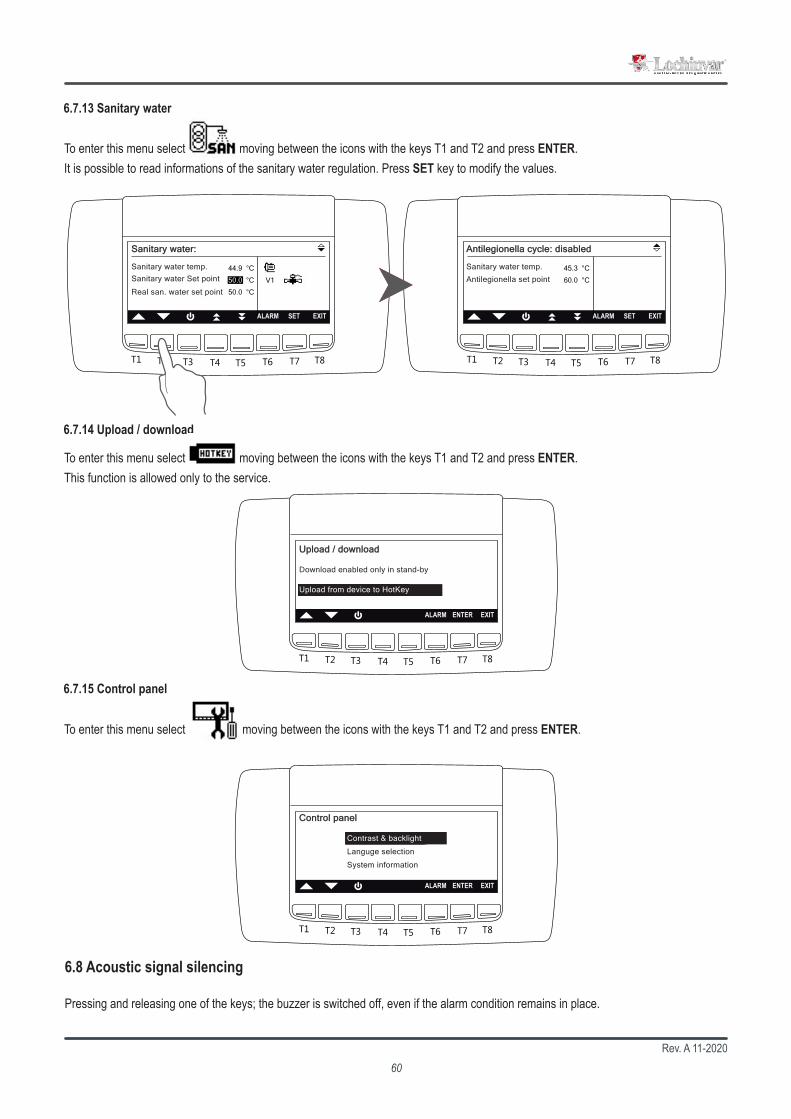
Rev. A 11-202060
T1 T2 T3 T4 T5 T6 T7 T8
SETALARM EXIT
44.9 °C
50.0 °C
50.0 °C
V1
T1 T2 T3 T4 T5 T6 T7 T8
SETALARM EXIT
45.3 °C
60.0 °C
T1 T2 T3 T4 T5 T6 T7 T8
ENTERALARM EXIT
T1 T2 T3 T4 T5 T6 T7 T8
ENTERALARM EXIT
6.7.13 Sanitary water
6.7.14 Upload / download
6.7.15 Control panel
Sanitary water:Sanitary water:
Sanitary water temp.Sanitary water Set point
Real san. water set point
Antilegionella cycle: disabledAntilegionella cycle: disabled
Sanitary water temp.
Antilegionella set point
Upload / downloadUpload / download
Download enabled only in stand-by
Upload from device to HotKey
Control panelControl panel
Contrast & backlight
Languge selection
System information
To enter this menu select moving between the icons with the keys T1 and T2 and press ENTER.It is possible to read informations of the sanitary water regulation. Press SET key to modify the values.
To enter this menu select moving between the icons with the keys T1 and T2 and press ENTER.This function is allowed only to the service.
To enter this menu select moving between the icons with the keys T1 and T2 and press ENTER.
Pressing and releasing one of the keys; the buzzer is switched off, even if the alarm condition remains in place.
6.8 Acoustic signal silencing

Rev. A 11-202061
7. MAINTENANCE OF THE UNIT
It is advisable to maintain a record book for the unit which details all operations performed on the unit as this will facilitate troubleshooting.
Maintenance must be performed in compliance with all requirements of the previous paragraphs.
Use personal protective equipment required by regulations as compressor casings and discharge pipes are at high temperatures. Coil fins are sharp and present a cutting hazard.
If the unit is not to be used during the winter period, the water contained in the pipes may freeze and cause serious damage. In this event, fully drain the water from the pipes, checking that all parts of the circuit are empty including any internal or external traps and siphons.
If it is necessary to replace a component of the machine, both for ordinary and extraordinary maintenance, this component must have the same or higher characteristics than those present. The same or higher performances or thicknesses are meant for the characteristics, which do not compromise the safety, the use, the handling, the storage, the pressures and the temperatures of use of the machine provided by the manufacturer.
The taps in the machine must always be in open position before starting. If it is necessary to disconnect the refrigera-tion circuit by closing the taps, it is necessary to take precautions to prevent the unit from starting up, even acciden-tally, and to indicate that the taps have been properly closed with special signs, both on the tap and in the electrical panel. In any case, the taps must remain closed as less as possible.
7.1 General warnings
Maintenance can:
• Keep the equipment operating efficiently• Prevent failures• Increase the equipment life
Starting from 01/01/2016 the new European Regulation 517_2014, “Obligations concerning the containment, use, recovery and destruction of fluorinated greenhouse gases used in stationary refrigeration, air conditioning and heat pumps”, became effective. This unit is subject to the following regulatory obligations, which have to be fulfilled by all operators:(a) Keeping the equipment records(b) Correct installation, maintenance and repair of equipment(c) Leakage control(d) Refrigerant recovery and disposal management(e) Presentation to the Ministry of the Environment of the annual declaration concerning the atmospheric emis-sions of fluorinated greenhouse gases.
7.2 Drive accessAccess to the unit once installed, should only be possible to authorized operators and technicians. The owner of the equipment is the com-pany legal representative, entity or person owns the property where the machine is installed.They are fully responsible for all safety rules given in this manual and regulations. If it is not possible to prevent access to the machine by outsiders, a fenced area around the machine at least 1.5 meters away from external surfaces in which operators and technicians only can operate, must be provided.

Rev. A 11-202062
The start-up operations should be performed in compliance with all requirements of the previous paragraphs.
All of the operations described in this chapter MUST BE PERFORMED BY TRAINED PERSONNEL ONLY. Before commencing service work on the unit ensure that the electric supply is disconnected. The top case and dischar-ge line of compressor are usually at high temperature. Care must be taken when working in their surroundings. Aluminium coil fins are very sharp and can cause serious wounds. Care must be taken when working in their surroundings. After servicing, replace the cover panels, fixing them with locking screws.
7.4 Periodical checks
If leak detection instruments are installed on the system, they must be inspected at least once a year, to make sure that they work properly.
If a defect is detected that compromises the reliable operation of the unit, the unit cannot be re-started until it has been repaired.
7.3 Scheduled maintenanceThe owner must make sure that the unit is periodically inspected, also on-site, adequately maintained, according to the type, size, age and use of the system, and to the indications contained in the Manual.Servicing during the unit’s operating lifetime and, in particular, scheduled leak detection, on-site inspections and check-ups of safety equipment, must be carried out as provided by local laws and regulations in force.
During its operating life, the unit shall be inspected and verified in accordance with applicable local laws and regulations. In particular, when there are no stricter specifications, the indications given in the following table (see EN 378-4, Annex D) must be followed, with reference to the situations described.
CASE Visual Inspection Pressure Test Search for leaks
A X X XB X X XC X XD X X
AInspection after an intervention with possible effects on the mechanical strength or after use change or in case the machine has not being working for more than two years. Replace all the components which are not suitable any more. Do not carry out checks at a higher pressure than the one indicated in the project.
B Inspection after a repair, or significant adjustment of the system, or its components. The check may be limited to the interested parts, but if a leakage of refrigerant is detected, a leakage search must be carried out on the entire system.
C Inspection after installation in a different position than the original one. Refer to point A when mechanical strength could have been affected by the change.
DLeak search, following a well-founded suspicion of refrigerant leakage. It is recommended examined the system for leakage, either directly (use of leak detection systems) or indirectly (deduction of leakage based on analysis of operating parameters), focusing on the parts most prone to leakage (e.g. joints).

Rev. A 11-202063
(1) If the unit is installed in strongly windy areas, near coasts or deserts or in areas subjects to wind and/or sand storms, or near airports, industries or in places with high levels of air pollution in general inspect the unit more frequently (every three months or more) to check the real condition of the surface protection.
(2) In order to carry out operations on the refrigerant, it is necessary to observe the European Regulation 517_2014, “Obligations regarding the containment, use, recovery and destruction of fluorinated greenhouse gases used in sta-tionary refrigeration, air conditioning and heat pump equipment”.
7.4.1 Electrical system and adjustment
Action to be performed Frequency
Monthly Every 2 months
Every 6 months
Every year
Every5 years
As neces-sary
Check that the unit works properly and that there are no active warnings XVisually inspect the unit XCheck noise and vibration level of the unit XCheck operation of safety features and of interblocks XCheck the unit’s performance XCheck the current draws of the different parts (compressors, fans, pumps, etc.) XCheck the supply voltage of the unit XCheck tightness of cables in their clamps XCheck the integrity of the insulating coating of power cables XCheck the conditions and functioning of the counters XCheck functioning of the microprocessor and of the display XClean the electrical and electronic components of any dust XCheck functioning and calibration of probes and transducers X
7.4.2 Condensing coils and fans
Action to be performed Frequency
Monthly Every 2 months
Every 6 months
Every year
Every5 years
As neces-sary
Visually inspect the coil XClean finned coils (1) XCheck the water flow and/or any leaks XCheck that the flow switch is working properly XClean the metal filter on the water line (3) XCheck noise and vibration level of the fans XCheck the supply voltage of the fans XCheck the fans’ electrical connections XCheck functioning and calibration of the fans’ speed adjustment system (if present) X
Check 4-way valve operation (if present) XCheck air presence in the hydraulic circuit XCheck color of moisture indicator on liquid line XCheck for freon leaks (2) X
(3) It can be carried out with a higher frequency (also weekly) depending on the ∆t.

Rev. A 11-202064
7.5 Refrigerant circuit repair
For leak detection, the system should be charged with nitrogen using a gas bottle with a pressure reducing valve, until 15 bar pressure is reached. Any leakage is detected using a bubble leak finder. If bubbles appear discharge the nitrogen from the circuit before brazing using the proper alloys.
If the refrigerant circuit is to be emptied, all the refrigerant must be recovered using the correct equipment.
Never use oxygen instead of nitrogen: explosions may occur.
Site assembled refrigerant circuits must be assembled and maintained carefully, in order to prevent malfunctions.
Therefore:• Avoid oil replenishment with products that are different from that specified and that are pre-loaded into the compressor.• In the event of a gas leakage on machines using refrigerant, even if it is only a partial leak, do not top up. The entire charge must be
recovered, the leak repaired and a new refigerant charge weighed in to the circuit.• When replacing any part of the refrigerant circuit, do not leave it exposed for more than 15 minutes.• It is important when replacing a compressor that the task be completed within the time specified above after removing the rubber sealing
caps.• When replacing the compressor following a burn out, it is advisable to wash the cooling system with appropriate products including a
filter for acid.• When under vacuum do not switch on the compressor.
Daily and monthly works may be carried out directly by the Owner of the system. All other works must be perfor-med by authorised and trained personnel.
Any kind of cleaning whatsoever is forbidden before disconnecting the device from power supply by turning the master switch to the OFF position. It is forbidden to touch the device while barefooted or with wet or damp body parts.
Works on the cooling line must be carried out by qualified and trained technicians, as provided by local laws and regulations in force.
7.4.3 Compressors
Action to be performed Frequency
Monthly Every 2 months
Every 6 months
Every year
Every5 years
As neces-sary
Visually inspect compressors XCheck noise and vibration level of the compressors XCheck the supply voltage of the compressors XCheck the compressors’ electrical connections XCheck the oil level in the compressors by checking the oil level light. XCheck that the crankcase heaters are powered and working properly XCheck the conditions of the compressors’ power cables and their tightness in the clamps X
Before the start-up it is necessary to carry out all the operations described in the previous tables and make the necessary checks provided by the pre-start control module (valid for the italian market) to be requested to the service.

Rev. A 11-202065
All decommissioning operations must be performed by authorized personnel in accordance with the national legisla-tion in force in the country where the unit is located.
8.1 Disconnect the unit8. DECOMMISSIONING
• Avoid spills or leaks into the environment.• Before disconnecting the machine please recover:
• the refrigerant gas;• Glycol mixture in the hydraulic circuit;• the compressor lubricating oil.
Before decommissioning the machine can be stored outdoors, providing that it has the electrical box, refrigerant circuit and hydraulic circuit intact and closed.
8.2 Disposal, recovery and recycling
8.3 RAEE Directive (only UE)
The frame and components, if unusable, should be taken apart and sorted by type, especially copper and aluminum that are present in large quantities in the machine.All materials must be recovered or disposed in accordance with national regulations.
The refrigerant circuit of the unit contains lubricant oil that binds the disposal mode of components .
This product is included in the application of Directive 2012/19/EU on the management of waste electrical and electronic equipment (WEEE).The unit should not be treated with household waste as it is made of different materials that can be recycled at the appropriate facilities.Inform through the municipal authority about the location of the ecological platforms that can receive the product for disposal and its subse-quent proper recycling.The product is not potentially dangerous for human health and the environment, as it does not contain dangerous substances as per Direc-tive 2011/65/EU (RoHS), but if abandoned in the environment it has a negative impact on the ecosystem.Read the instructions carefully before using the unit for the first time. It is recommended not to use the product for any purpose other than that for which it was designed, as there is a risk of electric shock if used improperly.
The crossed-out bin symbol on the label indicates that the product complies with regulations on waste electrical and electronic equipment.The abandonment of the equipment in the environment or its illegal disposal is punishable by law.
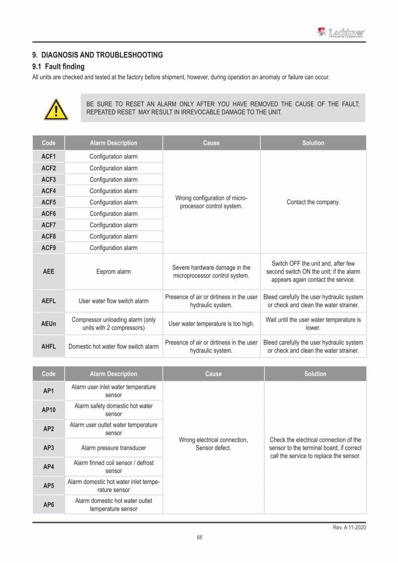
Rev. A 11-202066
9. DIAGNOSIS AND TROUBLESHOOTING9.1 Fault findingAll units are checked and tested at the factory before shipment, however, during operation an anomaly or failure can occur.
BE SURE TO RESET AN ALARM ONLY AFTER YOU HAVE REMOVED THE CAUSE OF THE FAULT; REPEATED RESET MAY RESULT IN IRREVOCABLE DAMAGE TO THE UNIT.
Code Alarm Description Cause Solution
ACF1 Configuration alarm
Wrong configuration of micro-processor control system. Contact the company.
ACF2 Configuration alarmACF3 Configuration alarmACF4 Configuration alarmACF5 Configuration alarmACF6 Configuration alarmACF7 Configuration alarmACF8 Configuration alarmACF9 Configuration alarm
AEE Eeprom alarm Severe hardware damage in the microprocessor control system.
Switch OFF the unit and, after few second switch ON the unit; if the alarm
appears again contact the service.
AEFL User water flow switch alarm Presence of air or dirtiness in the user hydraulic system.
Bleed carefully the user hydraulic system or check and clean the water strainer.
AEUn Compressor unloading alarm (only units with 2 compressors) User water temperature is too high. Wait until the user water temperature is
lower.
AHFL Domestic hot water flow switch alarm Presence of air or dirtiness in the user hydraulic system.
Bleed carefully the user hydraulic system or check and clean the water strainer.
Code Alarm Description Cause Solution
AP1 Alarm user inlet water temperature sensor
Wrong electrical connection, Sensor defect.
Check the electrical connection of the sensor to the terminal board, if correct call the service to replace the sensor.
AP10 Alarm safety domestic hot water sensor
AP2 Alarm user outlet water temperature sensor
AP3 Alarm pressure transducer
AP4 Alarm finned coil sensor / defrost sensor
AP5 Alarm domestic hot water inlet tempe-rature sensor
AP6 Alarm domestic hot water outlet temperature sensor
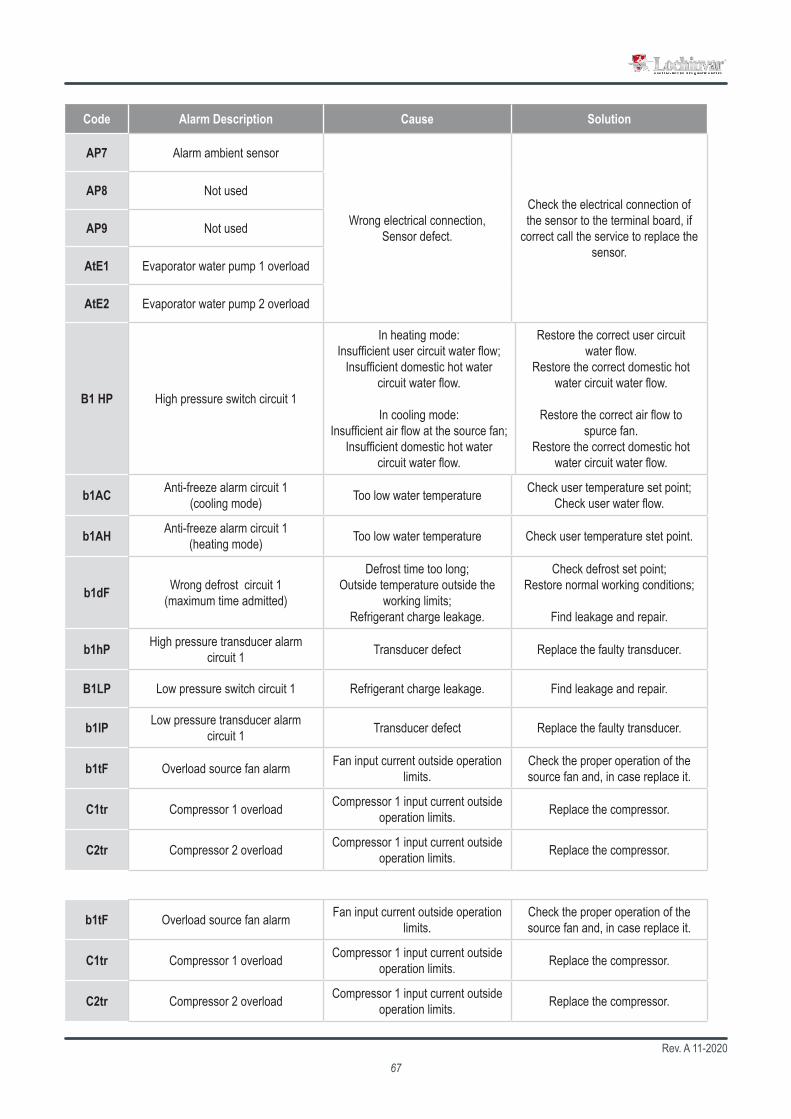
Rev. A 11-202067
Code Alarm Description Cause Solution
AP7 Alarm ambient sensor
Wrong electrical connection, Sensor defect.
Check the electrical connection of the sensor to the terminal board, if
correct call the service to replace the sensor.
AP8 Not used
AP9 Not used
AtE1 Evaporator water pump 1 overload
AtE2 Evaporator water pump 2 overload
B1 HP High pressure switch circuit 1
In heating mode:Insufficient user circuit water flow;
Insufficient domestic hot water circuit water flow.
In cooling mode:Insufficient air flow at the source fan;
Insufficient domestic hot water circuit water flow.
Restore the correct user circuit water flow.
Restore the correct domestic hot water circuit water flow.
Restore the correct air flow to spurce fan.
Restore the correct domestic hot water circuit water flow.
b1AC Anti-freeze alarm circuit 1 (cooling mode) Too low water temperature Check user temperature set point;
Check user water flow.
b1AH Anti-freeze alarm circuit 1 (heating mode) Too low water temperature Check user temperature stet point.
b1dF Wrong defrost circuit 1 (maximum time admitted)
Defrost time too long;Outside temperature outside the
working limits;Refrigerant charge leakage.
Check defrost set point;Restore normal working conditions;
Find leakage and repair.
b1hP High pressure transducer alarm circuit 1 Transducer defect Replace the faulty transducer.
B1LP Low pressure switch circuit 1 Refrigerant charge leakage. Find leakage and repair.
b1lP Low pressure transducer alarm circuit 1 Transducer defect Replace the faulty transducer.
b1tF Overload source fan alarm Fan input current outside operation limits.
Check the proper operation of the source fan and, in case replace it.
C1tr Compressor 1 overload Compressor 1 input current outside operation limits. Replace the compressor.
C2tr Compressor 2 overload Compressor 1 input current outside operation limits. Replace the compressor.

Lochinvar Ltd 7 Lombard Way
The MXL Centre, BanburyOxon, OX16 4TJ
+44 (0) 1295 [email protected]
www.lochinvar.ltd.uk
Reproduction, data storage and transmission, even partial, of this publication, in any form, without the prior written authorisation of the company, is prohibited. The company can be contacted for all inquiries regarding the use of its products. The company follows a policy of continuous product development and improvement and reserves the right to modify specifications, equipment and instructions regarding use and maintenance at any time, without notice.