air heater d 3 lc / d 3 lp / b 3 lc b 3 lp
TRANSCRIPT

Air Heater D 3 LC compact / D 3 LP compact / B 3 LC compact/ B 3 LP compact
Technical Description Installation Instructions
Engine-independent air heaters
B 3 LC compact/ B 3 LP compact tor gasoline
D 3 l C compact I B 3 L P compact for diesel fuel
Air Heater Cat No.
B 3 LC compacJ, 12 Volt 20 1767 05 00 00
D 3 L C compact, 12 Volt 25 1980 05 00 00
D 3 LC compact, 24 Volt 25 1981 05 DO 00
B 3 L p compecl. 12 VOit 20 1768 05 00 00
D 3 L P compact, 12 Volt 25 1982 OS 00 00
D 3 L P compact, 24 Volt 25 1983 05 00 00
Ebersp<'icher9
J, (bOl'S~;l.Chcr Gm~H&Co. Et:011pachur~t1. 24 0 · 7J130Esollr.gen
Tvie.1011 (.:tonvu1; (0711)909·00 Telet&K (0711)939-0500
Contents Page
Scope of delivery . . . . .. . . . . .. • . .. . . . .. . .. . . .. 2, 3 Approval, official regulations, general . . . . • . . . . 4 Typical installations/installation location . . . . . . 5 Installing the heater . .. • . . .. . .. .. . .. . . . .. . .. .. 5 Principal dimensions .. . . . . . . . . . . . . . . . . • .. . . . . 6 Permissible installation pos~ions . . . . . . . . . . . . . 6 Fastening to the vehicle wall .. .. .. .. .. .. .. .. .. 7 Running the heating air .. . .. .. .. . .. . .. .. .. .. . 7 Running the combustion air . . . . . . . . . .. .. .. . .. 8 Running the exhaust .. . . . .. .. .. . . . . .. .. .. . . . . 8 Fuel supply ...... .... ........................ 9, 10 Electrics/wiring diagrams . .. • • • .. . .. .. .. .. . .. 11 - 15 Function description .. ....................... 16. 17 Technical data ............ ................. .. 18
25 19809094 ~ 07 2000 Subjecl 10change Prin1edtl'I Germany OJ. EbO.I~ GmbH& Co. B 40
Visit www.butlertechnik.com for more technical information & downloads
www.butlertechnik.com

Scope of delivery (See figure on page 3)
Item
2
3
Designation
Heater (See page 1 for Cat. No.) Figures 1 - 3 are included
Metering pump with built-in fuel filter
Cap
To be ordered in addition:
The Concept
Universal installation kit for 13 3 LC compso! and D 3 L C comp•c< Cat. No. 25 1980 80 00 00 (air outlet d ia. 75 mm) or for B 3 L C com,ooc1. D 3 L C co:npsc1, 83 L Pand 0 3 L Pccmpac1 Cat. No. 25 1982 80 00 OD (air outlet dia. 90 mm)
Operating units (see right)
only for TRS 003 version: Cable. 8 m long Cat. Mo. 22 1000 30 93 OD
The B 3 LC "°'"'""'c1/D 3 L C oompaci/83 L P compoctf D 3 L P ccmo•cr can be used universally for heating truck cabs, minibuses. campers, ambulances, construct.ion machinery and boats.
To cater for the varying requirements as regards heating capacity, control, fuel. on-board voltage, noise, lenglh and diameter of heating air lines. current requirement and opera1ing comfort, we offer a number of different heater variants (see page 1 o f catalogue numbers), which can be expanded to obtain the required heating system.
The c versions have the highest heating capacity and air throughput. The result is a slightly greater b lower noise.
Where noise is an important factor. the P versions are used. fn these versions, heating capacity, heating air throoghput and blower noise have been reduced. See the specifications on page 1 for details. The electronic control unit is integrated in the heater. This facilitates wiring during installation. The heaters are suitab le ior installation in cabins o f vehicles for transporting hazardous goods and, if wired in the appropriate manner (see wiring diagram), meet TRS 003.
The Components
1. The basic heater will standard equipment is selected depending on the fuel and the on-board voltage: also C or P versions. with or without 'Off' control setting.
2. The universal installation kit is selected depending on whether a heating air outlet of 75 mm or 90 mm diameter is needed.
3. The operating device sele;eted depends on Uie visual appearance and the space availab le on the dashboard.
2
Control elements, optional
Quantity I Designation Order No.
1 Control unit 12 volt 25 t895 71 00 00 25 1896 71 00 00
• 24 volt
fio1ary switch fos ON i OFF and to adjvst ;;l".e heal flO\\'.
Mini -ctock - 12 / 24 volt 22 1000 31 31 00
• TI1e mni-c!cck can be oombined wilh the TP 41/ TP41 i 1a6io remot<J comrol. A<:ldi1io.'laUy required: Thee control uni! to adjuSl •he heat ilow and 1he chang-0.ov&1 switch 'lle.atir1gl 'lentilatir.g' ior ventilalion mode.
Module clock - 12 I 24 volt with temperature preselection
22 1000 30 38 00
with 1he T? <I / TP 4i rt'ld ~o remo1e CC<'ltrol.
-
The modu'e clcck can boce<nbioOO
Mounting parts ·module clock" 25 1482 70 01 00
Cf"lly requirQd wtlell ins~al!ing wi:h panel.
Radio remote control TP 4 22 1000 30 63 00
12 { 24 volt TP 4i " 22 1000 30 99 00
The radio remote cot1trol TP 4 / TP ~! can only bQ used in combination with the modvle cloc~-1..
1 Radio remote control TP 41 22 1000 31 35 DO
12/24volt TP 41 i" 22 1000313900
The t3.d:.0 rem::m~ conllci l'f' 41/TP41i can be used on its own e< in ccmbinatlon 'Nilll lll& mini-c!ock. o:de-rNo. 22 10003131 CO.
• Outside Germany, only the i-version radio remote controls may be permissible.
Please note! Control elements must be selected in accordance with the intended use of the AIRTRONIC and on the basis of the distinction: air or water heater. simple switching on and off, programme preselec tion and I or radio remote control. The control elements are supplied with operating instructions. These are intended to be handed over to the customer together with the mounting and operating instructions for the AIRTRONIC.
For further accessories. please refer to the accessories catalogue.
Visit www.butlertechnik.com for more technical information & downloads
www.butlertechnik.com

Scope of delivery
3
Visit www.butlertechnik.com for more technical information & downloads
www.butlertechnik.com

[fil Government regulations concerning installation
For installation in motor vehicles that are subject to the Regulations Authorising · the Use of Vehicles for Road Traffic (StVZO), the air heater has been approved by
the {German) Federal Office for Motor Traffic in keeping with the "General Model Approval" (ABG), and the official test symbol is marked on the type plate of the air heater
B 3 L C compact 'VV'v S 254
D 3 L C compact 'VV'v S 253
B 3 L P compact 'VV'v S 263
D 3 L P compact 'VV'v S 257
The mounting requirements associated with the General Model Approval (ABG) have been printed in the corresponding sections of these mounting instructions. When the air heater is installed in special vehicles, then the regulations governing such vehicles must be taken into account (e.g. TRS 003 for vehicles used to transport dangerous substances).
The year in which the air heater was operated for the first time must be permanently recorded on the type plate. The works must print 3 years in the corresponding field of the type plate. The valid year is identified by removing those years that are not applicable
Subsequent installation of the heater must be completed in conformity with these mounting instructions and must be accepted by an officially approved vehicle specialist or inspector (Section 7.4a of Annex VIII relating to StVZO) 1n conformity with§ 19 Section 4 StVZO. The specialist I inspector must issue a corresponding written certificate. The effectiveness of model acceptance (ABG) for the heater depends upon this certificate
The vehicle owner can choose the kind of certificate to be issued: • A separate "Acceptance Confirmation" must always be kept in the vehicle. Neu
tral acceptance confirmations of the motor vehicle specialist are also permissible. The vehicle manufacturer, the vehicle type and the vehicle identification number must all be entered in both cases.
• Entry in the vehicle registration book (by the assessing agency) and in the motor vehicle certificate (by the approving agency).
For vehicles that are not subject to StVZO (e.g. ships), it is necessary to observe the specific rules and mounting instructions applicable to the given vehicle; these can differ regionally.
The heater must be installed in keeping with these mounting instructions or possibly other special installation recommendations by a workshop approved by the manufacturer.
The installation points suggested in these mounting instructions are examples Alternative installation points are permissible provided they conform with the general installation requirements and, possibly, after consulting the manufacturer. This applies particularly to the electrical wiring (circuit diagram), the fuel supply, conducting the combustion air and exhaust gas and the use of alien operating and controlling elements. This is only permissible with the written approval of the manufacturer.
The sticker "Turn off the heater prior to refuelling", included with the heater, must be applied at an appropriate point on the vehicle (near the fuel tank cap).
Further mounting information (e.g. for boats and ships) can be requested from the manufacturer.
llliJ Safety instructions concerning installation
Every combustion process produces exhaust gas that contains toxic substances. Consequently, and on account of the high temperatures, the exhaust gas must be conducted in conformity with the requirements specified in these mounting instructions
Fuel pipes and exhaust pipes must be safely fastened, to avoid damage from vibrations (recommendation: at intervals of approx. 50 cm)
The hot-air emitter (possibly adjustable) must always be arranged in such a manner that the hot air is not directly blown onto heat-sensitive parts of the vehicle People and loose objects must not be directly exposed to the blown hot air. To avoid damage and burns, people and loose objects must not be directly exposed to the blowing hot air.
If there is no suction hose, then the suction side of the heater must be covered with a protective grille to prevent injury from the hot-air blower.
The heater may only be started up when the maintenance flap is closed.
The maintenance flap may not be open during operation.
Ensure that the insulation of electrical lines cannot be damaged due to abrasion, kinking, squeezing or by exposure to heat.
As a result of their concept for mobile service, the heaters are not suitable as permanent heating installations (for instance to heat living rooms).
4
[]] Government regulations concerning operation
Subsequent installation of the heater must be completed in conformity with these mounting instructions arid must be accepted by an officially approved vehicle specialist or inspector (TUV, DEKRA} in conformity with§ 19 Section 4 StVZO (Regulations Authorising the Use of Vehicles for Road Traffic), who must issue a corresponding written certificate, either by entry in the vehicle papers (vehicle registration book or motor vehicle certificate), or as a separate "Acceptance Confirmation" that must always be kept in the vehicle. The effectiveness of model acceptance for the heater (ABG) depends upon this certificate.
The heater must only be used for the purpose specified by the manufacturer with due consideration of the 'Technical Description I Mounting Instructions" and the "Operating Instructions" included with each heater.
It is not permissible to operate the heater where combustible vapours or dusts can be formed, e.g. in the vicinity of fuel, coal, wood and grain stores and similar facilities.
The heater must not be used in closed rooms, e.g. in a garage or car park building. This is because of the danger of poisoning since all combustion processes produce exhaust gases that contain toxic constituents.
The heater must be turned off when refuelling.
With vehicles subject to TRS regulations (transport of dangerous products, e.g. road tankers), the heater must be switched off before entering the hazardous area (refinery, petrol station, etc.}.
In conformity with StVZO, the heater must be exchanged for an original replacement healer by the manufacturer or an authorised workshop 10 years after the heater was first used. The vehicle owner I operator of the heater is responsible for ensuring replacement. A plate must then be mounted (not detachable) on the replacement heater indicating the date when the replacement heater was installed, together with the designation "Original Part" (the plate is supplied with the replacement heater).
D.l.Y. repairs (on your own and without using original spare parts) are dangerous and therefore not permitted. The General Model Approval (ABG) for the heater and the General Operating Permit (ABE) for the vehicle will both become invalid.
The manufacturer's guarantee for the entire heating system will become invalid if the above instructions are not observed. The Eberspacher Guarantee Conditions are exclusively applicable.
The observance of the pertinent regulations and safety instructions is a precondition for liability claims. The Eberspacher company cannot be held liable if the "Operating Instructions" have not been observed and if repairs have not been competently completed, even if original spares were used.
l25J Safety instructions concerning operation
As a result of its concept for mobile service, the heaters are not suitable as permanent heating installations (for instance to heat living rooms).
The installation space of the heater must remain free and cannot be used as storage space. Reserve fuel tanks, oil cans, spray cans, gas cartridges, lire extinguishers, cleaning cloths, clothes, paper, etc., must not be stored or transported on or alongside the heater
The protective grille over the suction side should be occasionally inspected, but particularly before the heating period, and cleaned should this prove to be necessary.
An adjustable hot-air emitter must always be arranged in such a manner that hot air is not directly blown onto heat-sensitive parts of the vehicle. People and loose objects must not be directly exposed to the stream of hot air. To avoid damage and burns, people and loose objects must not be directly exposed to the stream of hot air.
Defective fuses must only be replaced by fuses with the prescribed fuse rating
Should fuel leak out of the heater's fuel system, then the damage must be immediately rectified by an authorised servicing workshop.
The heater should be tested before the beginning of the heating period. The heater must be turned off, and the fuse removed so that it is inoperable, should intense smoke develop for an extended period, if unusual burner noises can be heard, if there is a distinct smell of fuel or if electric I electronic parts become overheated. Renewed operation of the heater is only permissible after it has been checked by trained specialist Eberspacher personnel.
Damage to the actual heater or the heating installation must only be remedied by an authorised servicing workshop which will only use original spare parts.
Visit www.butlertechnik.com for more technical information & downloads
www.butlertechnik.com

Typical installations/installation location
In truck:
1. On the rear wall of the cab 2. Under the seat of the driver or co-driver
In van:
DL~L
7"'. '- ''. '~\ ' ~-~m ', I ' i:: 1
: 1~_\.____ 9 ' ..
d --- I,.-~--,-----.,,
=~= l1 i 1 I / I
! : : l ! ... _ -'~ _..,,__ __ ; v 7 .l!!!!!!!!!I. ' ) 2 L.L4 c::::s,,~
5
Installing the heater
The heaters are suitable and approved for installation in vehicle areas used by persons. Installation in the driver or passenger areas of motor buses* is not permitted.
The heater must be fitted by its base on an outside panel of the vehicle or on the vehicle floor, using the seal seated on the base.
5
In excavator:
In the cab
1 Heater 2 Pipe elbow 3 Flexible pipe 4 Air outlet, rotatable 5 Flexible exhaust pipe 6 Intake silencer 7 Metering pump 8 Fuel branch piece 9 Operating unit
12 Control line 13 Protective grille
The factory plate must be clearly visible when the heater is installed. If necessary a second plate (duplicate) with the same information as the original can be affixed to a point on the heater clearly visible after installation or to a cover located in front of the heater. A second plate is not necessary if the original is visible after removal of a cover without the aid of tools.
• (Vehicles with more than 9 seats)
Visit www.butlertechnik.com for more technical information & downloads
www.butlertechnik.com

Principal Dimensions
422
-----____ _'.3~il _____ _
f--"5=0--r-~---- 179 __ -----~
~25 0 24
-____11Q_-L._&J
Permissible installation positions
---
6
~ 143
The heater should be installed in the standard position as shown.
Please consult the manufacturer if further differences are necessary.
During starting and thermostat operation, a heater installed in the standard position may be tilted - due to the inclination of the vehicle during motion - up to ±15° in both axes out of the standard position.
Continuous heating operation after starting is possible at a divergence of up to ±30° from the standard position. With inclinations exceeding ±30°, reliable heating operation is no longer possible. However, this does not lead to damage of the heater provided these changes in the operating position are only for brief periods.
Visit www.butlertechnik.com for more technical information & downloads
www.butlertechnik.com

Fastening to the vehicle wall/flor Make penetrations in accordance with the template pattern.
The mating surface for the heater base must be smooth. To drill the penetrations and if necessary to smooth the mating surface, a special tool is available from the manufacturer under Cat. No. 99120146 53 29.
Special tool
Running the heating air (example)
See the Additional Equipment Catalog for further
•This must be kept free. Check for free turning of fan wheel.
If the mating surface sheet is too thin (criterion: thinner than 1.5 mm), a reinforcing plate, Cat. No. 201577890003, can be installed additionally on the outside.
Vehicle panel
~--_1-.., I I I ~ 0 I I Y8 9 I I I L __ _
Heater
Reinforcing plate
Reinforcing plate
Vehicle panel /
Hex. nut
1%x. . tightening
Seal
I/~ torque / 6 Nm
Spring washer
accessories. ~;;::~~r---i
6 8 8 6 7
When checking an installation, the average output temperature should not significantly exceed 110° Cat the output point when the intake temperature is 20° C. This ensures that the safety thermal cutout switch will not respond under normal operating conditions.
(B3LP 1 Protective grille compact
2 Reducing piece, straight, 75 or 90 mm diameter} ~n: LP 3 Reducing piece, 90°, 75 or 90 mm diameter compact 4 Flexible pipe, dia. 75 mm only 4a Flexible pipe, 75 or 90 mm diameter 90 mm} 5 Air outlet, rotatable 6 Connection piece 7 Protective grille 8 Hose clip
7
3
The heating air intake openings shall be arranged in such a manner that exhaust from the vehicle's engine and from the heater cannot be expected to be sucked in under normal operating conditions, and the heating air cannot be contaminated.
When operating as a recirculating heater, locate the inlet for the recirculating air in such a way that the outflowing hot air cannot be sucked directly in again. Permissible heating air intake temperature max. 40° C.
Visit www.butlertechnik.com for more technical information & downloads
www.butlertechnik.com

Running the combustion air/Running the exhaust
Permissible diameters, lengths and curvatures of combustion air and exhaust lines.
E
~ <cl )
E
Internal dia. '6 25mm Cti
iiiii·~=~ i';==;;;;;;;;;;~==;;;;';;;;;;;j4~" / i------m-a_x_2_m ______ ~-I i-------m-in-.-0-.2-to-m-ax-.-2-m _____ __, \ .
air Combustion
Protect . Protect from slipstream, from slipstream, snow, dirt and snow, dirt and water. water.
Permissible diversions - exhaust line: max. 180°; combustion air line: max. 180°
Running the combustion air
The supplied silencer at least must be fitted to the combustion air intake connection. It is permissible to extend it to a total of 2 m (including silencer).
The silencer must then be fitted to the free end of the extension.
Additional noise suppression is possible by installing an exhaust silencer (see the section on exhaust parts in the Additional Equipment Catalog). The permissible length of the exhaust line is reduced by the length of the exhaust silencer here.
The combustion air must be sucked in from the outside (and not from the passenger area or luggage compartment).
Do not install the intake opening of the combustion air line facing the slipstream, but run it such that it can nor be clogged with dirt and snow, and such that any water which does enter can also flow out.
Fit the end sleeve. This ensures that a ball of 16 mm dia. cannot be inserted (a requirement in the "Technical Requirements for Heaters"). In very dusty conditions, an oil filter must be used on the combustion air side.
8
Running the exhaust
The scope of delivery includes a flexible exhaust hose, 24 mm internal dia., 1 m long. This can be shortened as required. For longer lines see the Additional Equipment Catalog.
Exhaust lines must not project beyond the sides of the vehicle. They must be laid either with a slight slope or provided with 5 mm drain holes at the lowest points for draining off the condensate.
Arrange the exhaust outlet and the combustion air intake such that the exhaust cannot be sucked directly back inside.
The exhaust outlet must be on the outside. Exhaust lines must be laid such that neither the penetration of exhaust into the vehicle interior nor the intake of exhaust through the vehicle or heater blowers need be expected'', and that the operation of essential vehicle components is not impaired (ensure adequate clearance). Do not install the outlet opening of the exhaust line facing the slipstream, but run it such that it cannot be clogged with dirt and snow, and such that any water which does enter can also flow out.
The end sleeve provided on the end of the exhaust pipe ensures that a ball of 16 mm dia. cannot be inserted (a requirement in the "Technical Requirements for Heaters").
1J This requirement can be conSidered met if the outlet opening of the exhaust line is positioned above, at the side of, or - if the exhaust is routed underneath the vehicle floor- near the side or rear of the cab or vehicle.
Visit www.butlertechnik.com for more technical information & downloads
www.butlertechnik.com

Fuel supply Divergences from the instructions set forth here are not permitted, as they can lead to malfunctions. 1. For cars with diesel engines, and for cars with petrol engines having mechanical pump.
Fuel tapped from the fuel supply line to the engine.
Precondition: The fuel line from the fuel tank to the engine must be leak-free, so that there is no break in the fuel column when the engine is not running.
Fuel connection to heater ____ __..r..._1ii--............_
1 ! ifu mechanical fuel pump • _r
1~11~.;;.1•il==~q To engine
i I " l "' '";"''"" """" 1
L_ ____ :_,l'i'. ___ a __ _j l 6
·"'~ Dimension a= max. 2 m with petrol
max. 5 m with diesel Dimension b= 50 mm Dimension c = max. 300 mm Dimension d = max. 4 m with petrol
max. 6m with diesel '
2. For cars with petrol injection engines and for trucks with diesel engines.
Tapping fuel from the supply line downstream of the delivery pump is prohibited in cars, since pressures of up to 10 bars can occur.
The fpllowing possibilities are available: 2.1 Tapping fuel - where possible - using a separate riser pipe, fitted to the fuel tank fitting in the case of cars, an directly into
the fuel tank in the case of trucks.
------;::>To engine (~,------¢= Return line to engine
Connection 11 I , forcars ~· 6
Internal fuel tank pump
- '" 11 '
__11_[12_...___~~'3~1 10: Connection
I for trucks II :a II • 11 • 1 I ,L, I ' ' I L"
I Dimension a= max. 2 m with petrol
max. 5 m with diesel Dimension d = max. 4 m with petrol
max. 6 m with diesel
2.2 lf it is not possible to fit a separate riser pipe in the case of cars with petrol injection engines, the return line can be tapped using a T-piece. Conditions: 1. There must be no valve installed in the return line of the fuel tank. 2. The pressure in the return line must not exceed 2 bars. For pressures greater than 0.3 bars and up to 2 bars, a pressure
reducing valve (additional equipment Cat. No. 201645 89 30 00) must be provided upstream of the metering pump. 2.3-lf it is not possible to fit a separate riser pipe in the case of trucks with diesel engines, the fuel supply line can be
tapped (as shown under 1.).
1 Fuel tank (vehicle tank or separate tank) 2 Fuel branch 3 Fuel hose, internal dia. 5 mm
Cat. No. 360 7 5 350 4 Fuel pre-filter
(only necessary when contaminated fuel is used) Cat. No. 251226 89 00 37
5 Fuel metering pump (15° to vertically upwards) 6 Fuel hose, internal dia.3.5 mm
Cat. No. 360 7 5 300 7 Fuel pipe, plastic, internal dia. 1.5 mm
Cat. No. 090 31118
9
8 Riser pipe, internal dia. 2 mm } external dia. 4 mm Cat. No.
9 Connection socket 20 1645 89 35 00 external dia. 4 mm
10 Riser pipe, internal dia. 2 mm Cat. No. 25 1226 89 50 00 external dia. 6 mm
11 Fuel pipe, internal dia. 2 mm Cat. No. 090 31125
Visit www.butlertechnik.com for more technical information & downloads
www.butlertechnik.com

3. Permissible suction and pressure heads for installation per 1. and 2.; permissible positioning of metering pump
max. fuel level Fuel line connection to heater . ---
~ g ~' 150 to vertical
A \ ,::, . 10. -~\-150
~,:--~1 ... -·!•1.
e
Supply pressure from tank to metering pump: e = max. 3000 mm suction head: tank at zero pressure
f = max. 500 mm with gasoline max. 1000 mm with diesel oil
Check whether tank ventilation works properly
intake from tank when underpressure occurs during operation (valve 0.03 bar in tank cap) f = max. 150 mm with gasoline
max. 400 mm with diesel oil
Pressure head metering pump to heater: g = max. 2000 mm f ____ J_
min. fuel level
Metering pump 24/141b Fuel line metering pump to heater should not have a slope if
at all possible.
4. Important
Protect fuel lines, filter and metering pump from overheating; do not install near silencers and exhaust pipes. Temperatures above 30° C lead to gas bubbles and problems with gasoline.
When installing the fuel line, fuel filter and fuel metering pump near the rear axle, be sure to takte the spring deflection of the rear axle into consideration.
Cut fuel tubes and pipes to length only with a sharp knife. Cuts may not be indented and must be burr·free.
For connection of the fuel branches, always use rubber tubing, never plastic pipe.
Fuel grade for dieselheaters
The heater can take without problem the fuel you use in your tank and which is commercially available. In the USA diesel fuel no. 1 and no. 2. Admixture of used oil is not permitted.
The refineries automatically adapt their fuels to normal win· ter temperatures (Winter Diesel).
Therefore difficulties can only arise at extremely low temperature (as in the engine - see the vehicle's instruction manual).
If the heater is operated from a separate tank, the following rules must be observed: at temperatures above o° C any type of diesel fuel can be used. · If no special cold-weather diesel fuel is available at low tempe· ratures, mix k.erosine or gasoline according to the adjacent table.
10
Fuel pipes connected by means of a fuel tube.
Fuel pipe sections must abut.
Do not let fuel tube sag.
Temperature Winter diesel fuel Additive
0° to-15°C**
- 15° to -25°C
-25° to -40° C
100°/o
500/o
* or special winter diesel fuels.
50010 Petroleum or petrol
100 °/o Petoleum*
.... or in accordance with fuel manufacturer's specifications.
The fuel line and the fuel pump niust be filled with new fuel by operation foF15 minutes.
Fuel for special cases
In special cases, the heaters can also be operated with extralight fuel oil {above 0° C) or petroleum. If in doubt, please consult the manufacturer.
Visit www.butlertechnik.com for more technical information & downloads
www.butlertechnik.com

Electrics:
Electrical lines and switching and control equipment must be arranged inside the vehicle so that their correct functioning is not impaired under normal operating conditions.
Fit the current regulator so that it 1s protected from splash water (from both its own vehicle and preceding ones). Outside installation is thus not permissible. The unit is best arranged in the vehicle interior, with the plugs pointing downward.
The pilot li"ght (built into the operating unit) should be within the field of vision of the driver, or at least be visible to him without great effort.
Operating unit and Mini-timer
The operating unit (see page 2 for Cat. No.) comprises the On-Off switch with controller for the heating capacity, a red light for illumination, and a green operation pilot light. Two scale discs are supplied with the operating unit.
Scale disc 1 is fitted if operation is exclusively with the operating unit. The operating unit then serves as an Onswitch and temperature controller.
Scale disc 2 is fitted if a Mini-timer is used for actuatio". Switch-on is then exclusively with the Mini-timer, and the temperature is selected with the rotary knob. See wiring diagram for connection. Remove the protective film before fitting.
~~ lo;
~'<I
1
Fitting dimension for the operating knob 0.5 to max. 1 mm.
~ (DJ
~'<I
2
0,5-max.1mm
11
The following line cross-sections must be maintained between the battery and the heater in order not to exceed the maximum permissible voltage loss of 0.5 V with 12 V rated voltage and 1 V with 24 V rated voltage in the lines.
Length+ and - < 5 m ~cross-section 4 mm2
Length + and - 5 to 8 m ~cross-section 6 mm 2
If the connection of the positive line is made at the fuse box (e.g. terminal 30), the vehicle's own line from the battery to the fuse box must be allowed for in the calculation of the overall line length, and if necessary redimensioned in accordance with the above information.
Coat the plug and earth connections outside the interior with contact protection grease.
Temperature control
The »High I Medium I Low I Off« settings are provided for temperature control.
A temperature sensor is arranged on the intake side of the heater, and - in conjunction with the controller of the operating unit - switches the heater to "High", "Medium" or "Low" or "Off" depending on the intake temperature and the controller setting. This type of temperature sensor is only suitable for recirculated-air operation (heating air intake from the space being heated). If the heater is operated with fresh air, an external temperature sensor (for Cat. No. see page 2) must be fitted in the interior and connected according to the wiring diagram. The sensor must not be attached to uninsulated outer panels, and must be protected from draughts and direct sunlight. See wiring diagram for connection.
Visit www.butlertechnik.com for more technical information & downloads
www.butlertechnik.com

Wiring diagram heater, normal version
'GD Gml'''''""I I
I 1.2 ~ I ~L~~~!!:li~ I _J I I J TTTl flfTUl I 1 2 3-,-,-,-1-e910i!12 13 14
...._ -1-1---L~ --v --v -v-
-~-1~ >- -------
Parts list
1.1 1 2 1.5 1.12 2.1 2.2 2.7
2.7.1 5.1
Burner motor Glow plug Overheating sensor Flame sensor Controller Dosing pump Main fuse 12volt=25A 24 volt= 15 A Fuse, actuation 5 A Battery
-N
•
Qrf't 1,0
br 1,0
b )--l
•S 2 5
N -" •
rt 0,5 ~0.5
11'0.5 wart 0,5
' bl'0,5 blws 0.5
' grM 0,5
' brws 0,5
~ -" @ @)
rt 1,0 -"
@~
ltd br 4,0
a) Connect the control elements and external sensors according to the "Control Elements" circuit diagram •rt Supply plus terminal 30 • ge Switch-on siQnal S+ •gr Temperature - actual value • wsrt Switch off theft warning
system • br Supply minus terminal 31 • blws Diagnosis • grrt Temperature - target value • brws Sensor reference signal
12
Cable colours
SW= black ws = white rt = red ge = yellow gn = green vi violet br brown gr grey bl blew Ii purple
25 1976 00 96 01 B
b) Optional • Fresh-air blower and I or • separate fresh air fan
Visit www.butlertechnik.com for more technical information & downloads
www.butlertechnik.com

Circuit diagram, control elements
SI Bl
~ fflli ~~
It ' ' 52 B2
___ jrp
___ irp ~-_r' ~ ~ ~
~---~+-~
al
c\M goo_,
....i!:..!:..!. ~
l>ro.! b1 .. u
",_,,._.,,,_j ~O.Jl
25 1895 00 97 02 A
"
85
13
Parts list
2.15.1 Sensor, room temperature 2.15.9 Sensor, outside temperature 3.1.11 Operating unit 3.1.16 Momentary-contact switch 3.2.8 Module clock 3.2.12 Timer 3.3.6 Radio receiver 3.9.1 Diagnosis unit, JE diagnosis
a) Connect the control elements to the heater •rt Supply plus terminal 30 • ge Switch-on signal S+ •gr Temperature - actual value • wsrt Switch off theft warning system • br Supply minus terminal 31 • blws Diagnosis • grrt Temperature - target value • brws Connection to earth for external temperature
sensor and temperature target value
b) Terminal 15 - necessary when connecting TP 4
c) Lighting terminal 58
d) Connection for diagnosis unit
e) Connection for external temperature sensor
g) Connection for external heater key oo
h) Connection for TP4 remote control
j) Connection for outside temperature sensor
k) When connecting an automatic switch or radio receiver - cut open wire at this point
I) Connection change-over switch 'heating I ventilating' (optional). How to start: operate change-over switch 'heating I ventilating', then switch on the heater.
Cable ends that are not being used must be insulated.
Plug and socket case are shown from the cable entry side.
Cable colours
SW= black ws = white rt = red ge = yellow gn = green vi violet br brown gr grey bl blew Ii purple
Visit www.butlertechnik.com for more technical information & downloads
www.butlertechnik.com
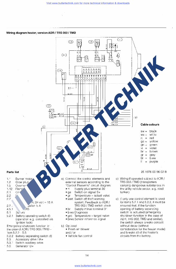
Wiring diagram heater, version ADR I TRS 003 / TMD
I F L ~_L_!__§__!__!!_R~I --rl __J
r::cmJTT[mJ_ ---
I ~
I 2 3 4 5 6 1 a 9 10 11 12 13 U ~---cc,-------
~1- I-- ---------
bl__J
WS 2.5
. . . " " " ' t '
@
~ nnrt 1.0
br 1.0 I
@b /
c I I
----- --- -- ---;; ---e-
l i • t
I Kl.15 @
I b 0
@ • L_ t I
@) d[ § I ~-
[ h rt 1.0 I
" " _'C_,
~@)dl I . " 0 0 I
' "'' @r-E I _, -~ I I I
Q
_l:f>= " I
® _JI br 4,0
Parts list @) .. ------- _____________ __J
1.1 Burner motor 1.2 Glow plug 1.5 Overheating sensor 1 .12 Flame sensor 2.1 2.2 2.7
2.7.1 4.5.1 5.1
Controller Dosing pump Main fuse 12 volt= 25 A; 24 volt= 15 A Fuse, actuation 5 A Diode TRS Battery
5.2.1 Battery operating switch d) (operation e.g. controlled via ignition lock)
Emergency-shutdown function in the case of ADR I TRS 003 / TMD -item 5.2.2 - 5.5 5.2.2 Battery separating switch d) 5.3 Accessory drive HA+ 5.3.1 Switch auxiliary drive 5.5 Generator D+
a) Connect the control elements and external sensors according to the "Control Elements" circuit diagram •rt Supply plus terminal 30 • ge Switch-on signal S+ •gr Temperature - actual value • wsrt Switch off theft warning
system; Feedback to ADR I TRS 003 I TMD switch clock
• br Supply minus terminal 31 • blws Diagnosis • grrt Temperature - target value • brws Sensor reference signal
b) Optional • Fresh-air blower and I or • Vehicle fan control
14
rt 0,5 ge 0,5
gr 0,5
•Srt 0,5 bl' 0.5 al
bl•s 0,5 grrt 0,5
br•s 0.5 Cable colours
SW= black ws = white rt = red ge = yellow gn = green vi violet br brown gr grey bl blew Ii purple
25 1976 00 96 02 B
c) Wiring if operated subject to ADR I TRS 003 / TMD (transporters carrying dangerous substances in the utility vehicle sector, e.g. road tanker)
d) If only one control element is used for items 5.2.1 and 5.2.2, it must be ensured that, if the function opening of battery separating switch' is actuated (emergency shutdown-function in the case of ADR, TRS 003, TMD and similar), the switch always breaks contact without delay (without consideration for t_he heater mode) and breaks all of the heater's circuits from the battery.
Visit www.butlertechnik.com for more technical information & downloads
www.butlertechnik.com

Circuit diagram, control elements - ADR I TRS 003 / TMD
rt D.5 BJ
ge 0.5
I
rcr~n----;,-;:--1 GJJD ~ I l~l~IST'
BJ
al ~ 0 " br 0. 5
i:!=~® ~ grrt 0. 5
brws 0. 5
rt O 5
ge 0.5 I
~
al wsrt O_ 5
br 0_5
blws 0 5 I grrt 0 5 I brws 0.5
86
al ~'----- ------c ~·~
1
J r1, ~ I '('"'''""" ,
-"-°-'----- .---,----k l~I I wsrt 0. J I I • ' ' • , -ii.;J,---[-J_ ___ _j_ ___ -k!:! . I w:;-,o:-,---- -L L ___ t!:! I ~ di Li':' _______ j
~el
-~~:l_ ___ ~_ _ __ _5~cTI]' wsrt 0.5 ' ' 1 '
br 0.5 ,------O'::' ~
~I ~s....2:_5 ________ _
Parts list
2.15.1 Sensor, room temperature 3.1.11 Control unit, round 3.2.8 Module clock (ADR I TRS 003 / TMD -
potentiometer) 3.9.1 Diagnosis, JE-diagnosis
a) Connect the control elements to the heater •rt Supply plus terminal 30 • ge Switch-on signal S+ •gr Temperature - actual value • wsrt Feedback to ADR I TRS 003 I TMD switch clock
Switch off theft warning system • br Supply minus terminal 31 • blws Diagnosis • grrt Temperature - target value • brws Connection to earth for external temperature
sensor and temperature target value
15
85
rn1~i10ii (Ql(g(g@l[l
B6 Cable colours 0 II 1 l21i l4 I 5I ol1lsll O
SW= black WS = white rt = red ge = yellow gn = green vi violet br brown gr grey bl blew Ii purple
25 2069 00 99 01 A
b) Terminal 15 c) Lighting terminal 58 d) Connection for diagnosis unit e) Connection for external temperature sensor g) Connection for external heater key liD
Cable ends that are not being used must be insulated.
Plug and socket case are shown from the cable entry side.
Visit www.butlertechnik.com for more technical information & downloads
www.butlertechnik.com

Functional description
Controls
1. Operating unit The operating unit is for switching the heater on and off and for setting the desired cabin temperatures (intake air temperature between 10 °C and 30 °C). The integrated green LED indicates whether the heater is on.
2. Heater timer (optional) With the heater timer, the heater can be switched on or off immediately or the switch-on time preset (between 24 hand 7 days depending on version).
Mode of operation.
Switch-on
The green pilot light comes on when the heater is switched on. The glow plug is switched on and the blower starts up at a low speed. Note: If the heat exchanger still contains residual heat, only the blower runs (cold-blowing phase). The start-up procedure commences after residual heat has dissipated.
Start-up procedure
Fuel feed starts after approx. 15 seconds. The fuel/air mixture ignites. Blower speed and fuel feed are increased continuously. Once a flame is detected and the combustion process has stabilized, the glow plug is switched off. The heater is heated up rapidly in the »POWER« setting at maximum heat flow until the heat exchanger reaches its operating temperature. Note: The duration of max. heat flow is temperaturedependent.
Control during heating
During heating, the cabin temperature or the intake heating air temperature is measured constantly and compared with the temperature set at the operating unit. If the measured temperature exceeds the desired cabin temperature, the heater switches to the »LOW« setting and continues to run at low blower motor speed. If the heating capacity in the »LOW« setting is insufficient, the heater switches to the »MEDIUM« setting. The blower continues to run at low speed. In most cases, the LOW-MEDIUM-LOW control sequence at low blower speed will supply the required heat. If the »MEDIUM« setting is not sufficient, the heater switches back to »HIGH«. This again entails full blower speed. lfin special cases an even lower heating capacity is required than the heater delivers in the »LOW« setting, the heater switches to the »OFF« setting. Restart is generally in the »MEDIUM" setting at low blower motor speed.
Switch-off
When the heater is switched off, the green pilot light goes out and the fuel feed is shut off. The blower continues to run to cool down the heater.
The glow plug remains switched on for another 15 seconds to clear the heater of combustion residues. Note: If no fuel feed took place during the start-up procedure or if the heater is in the »OFF« setting, the heater is switched off immediately without afterrun.
16
Once the normal afterrun period has elapsed, the heater is constantly after-ventilated at minimum blower speed (in recirculated-air operation only) until the heater is restarted.
Controls and safety equipment
The flame is monitored by the flame sensor, and the max. permissible temperature by the safety thermal cutout switch. Both affect the control unit, which shuts down the heater in th_e event of faults.
1. If the heater fails to ignite within 90 seconds of the start of fuel pumping, starting is repeated as described. If the heater still fails to ignite after 90 seconds of fuel pumping, fault shutdown takes place. If the heater does not ignite after 5 attempts to start, it is put permanently out of action (refer to the Troubleshooting and Repair Manual).
2. If the flame goes out spontaneously during operation, a restart is first attempted. If the heater fails to ignite within 90 seconds of fuel pumping being switched on, or if it does ignite but goes out again within 10 minutes, fault shutdown takes place. The heater can be reset by switching it off and then back on again.
3. In the event of overheating, the safety thermal cutout switch is operated, the fuel supply is interrupted, and fault shutdown takes place. Once the cause of the overheat has been removed, the heater can be restarted by switching it off and then back on again.
4. If the voltage drops below 10.5 or 21 V or rises above 15 or 30 Vas the case may be, fault shutdown takes place.
5 .. If the glow plug is defective or the electric cable to the metering pump is interrupted, the heater will not start.
6. When the heater starts, the operation of the blower motor is checked once. If it does not start, the heater reacts as for fault. During operation, the blower motor is monitored. If the motor speed is below the allowed limit, fault shutdown follows.
7. When the heater is switched off, the glow plug is switched on during the delayed shutdown for about 15 seconds (after-glow) to clear it of combustion residues.
Please note:
When carrying out electric welding work on the vehicle, disconnect the positive terminal from the battery and earth it in order to protect the control unit.
When checking the operation of the heater, turn the operating unit right up to the "High" setting.
Visit www.butlertechnik.com for more technical information & downloads
www.butlertechnik.com

Sectional drawing
12V-25A 24V-15A
5
2
1 Hot air blower wheel 2 Blower motor 3 Combustion air blower wheel 4 Glow plug 5 Control unit 6 Safety thermal cutout switch 7 Combustin chamber 8 Flame monitor 9 Heat exchanger 10 Heater timer
11 12 13 14 15 16 17 18
6 B 9
12
ifJlllllllll~
Outercasing F = fresh air Exhaust line Flange seal V =combustion air Fuel line Main fuse, 25 A B = fuel Combustion air intake line Fuel metering pump w = hot air Fuel strainer
A= exhaust
17
Visit www.butlertechnik.com for more technical information & downloads
www.butlertechnik.com

Technical Data
Heating medium
Heater settings
Fuel
Heating capacity Power High
Medium Low
Hot air throughput without counterpressure Power
High Medium
Low Off
Fuel consumption Power High
Medium Low
Electric power consumption 12 v on start-up 24 v
Electric power consumption Power in operation High
Medium Low Off
Ambient temperature storage operation, heater
operation, metering pump
Heating air intake temperature
Rated voltage
Minimum voltage
Maximum voltage
Radio interference suppression level
Ventilation operation
Weight
Heating operation at high altitudes up to 1500 m over 1500 m
B 3 L C compact D 3 L C compact B 3 L P compact D 3 L P compact
Air
Power I High I Medium I Low I Off
Gasoline Diesel Gasoline Diesel
3500 3500 3000 3000 w 3200 3200 2500 2500 w 1500 1500 1500 1500 w 1000 1000 900 900 w
160 160 140 140 kg/h 160 160 130 130 kg/h 80 80 85 85 kg/h 65 65 60 60 kg/h 25 25 30 30 kg/h
0.47 0.42 0.40 0.36 l/h 0.42 0.37 0.34 0.30 l/h 0.20 0.18 0.20 0.18 l/h 0.13 0.12 0.12 0.11 l/h
270 270 260 260 w 240 230 w
36 36 26 26W 36 36 22 22W 12 12 15 15 w 8 8 8 8W 5 5 6 6W
-40°C to+ 85°C -40°C to + 85°C -40°C to + 85°C -40°C to+ 85°C -40°C to + 50°C -40°C to + 70°C -40°C to+ 50°C -40°C to + 70°C -40°C to + 20°C -40°C to + 50°C -40°C to+ 20°C -40°C to + 50°C
max.+ 40°C
12 V or 24 V
10.5 V or 21 V An undervoltage protection device incorporated in the control
unit cuts out at approx. 10.5 V or 21 V.
16 V or 32 V An overvoltage protection device incorporated in the control
unit cuts out at approx. 16 V or 32 V.
Level 3; additional radio interference suppression measures possible
not possible
approx. 6 kg
Unrestricted heating operation possible. Heating operation is possible during a short stay. If a longer stay is planned, the fuel supply has to be adapted to the altitude. In this case, please consult the heater manufacturer for advice.
Value variations: +/-10o/o
18
Visit www.butlertechnik.com for more technical information & downloads
www.butlertechnik.com