air force institute of technologydtic.mil/dtic/tr/fulltext/u2/a420762.pdf · air force institute of...
TRANSCRIPT
INTERNET PROTOCOL (IP) OVER LINK-16
THESIS
Clinton W. Stinson, Captain, USAF
AFIT/GCE/ENG/03-04
DEPARTMENT OF THE AIR FORCE AIR UNIVERSITY
AIR FORCE INSTITUTE OF TECHNOLOGY
Wright-Patterson Air Force Base, Ohio
APPROVED FOR PUBLIC RELEASE; DISTRIBUTION UNLIMITED.

The views expressed in this thesis are those of the author and do not reflect the official policy or
position of the United States Air Force, Department of Defense, or the United States Government.

AFIT/GCE/ENG/03-04
INTERNET PROTOCOL (IP) OVER LINK-16
THESIS
Presented to the Faculty
Department of Electrical and Computer Engineering
Graduate School of Engineering and Management
Air Force Institute of Technology
Air University
Air Education and Training Command
In Partial Fulfillment of the Requirements for the
Degree of Master of Science in Computer Engineering
Clinton W. Stinson, B.S.
Captain, USAF
March 2003
APPROVED FOR PUBLIC RELEASE; DISTRIBUTION UNLIMITED.
-
AFlT/GCFJENG/O3-04
INTERNET PROTOCOL (IP) OVER LINK-16
Clinton W. Stinson, B.S.
Captain, USAF1.
Approved:
.J .-!)-c{;J, .I) I!/. J<- JUC(("'~3~ L~r ~st~ t~~~~~~:===~::::==- date
Thesis Advisor
n ~ n n .1'2- ""'Ail...Oj-'(::f:::~ ~~g H~~~~=~~~-- date
Committee Member
r
~ 0 ~ I :L1>1£.t 0';Dr. Richard A. Raines dateCommittee Member
---t:1~~~~ : . -~. L J- AQ,... </:; 2LDr. Michael A emple dateCommittee Member

Acknowledgements
I would like to express my sincere appreciation to my thesis advisor, Major Baldwin, for his
guidance and support throughout the course of this thesis effort. His insight, technical knowledge,
and experience were greatly appreciated. I would also like to recognize my thesis committee
members, Dr. Raines, Dr. Gunsch, and Dr. Temple, for their assistance and suggestions throughout
this process. In addition, I would like to thank my sponsor, Mr. Todd Reinhart, from the Air Force
Research Lab Sensors Directorate (AFRL/IFTA) for his support provided during this endeavor and
to Mrs. Gotfried of Raytheon, who provided timely information concerning the EISA program.
1Lt Dooley, of the AFRL Sensors Directorate (AFRL/IFSD), also provided invaluable assistance
to questions that arose concerning the Link-16 OPNET model.
Clinton W. Stinson
i
Table of Contents
Page List of Figures...................................................................................................................................... v
List of Tables..................................................................................................................................... vii
Abstract............................................................................................................................................... ix
I. Introduction..........................................................................................................................1-1
1.1 Background ..........................................................................................................1-1
1.2 Goals.....................................................................................................................1-3
1.3 Document Overview ............................................................................................1-4
II. Literature Review ................................................................................................................2-1
2.1 Introduction ..........................................................................................................2-1
2.2 Scenario ................................................................................................................2-1
2.3 Notional Communications Architecture..............................................................2-4
2.4 Information Assurance Capabilities ....................................................................2-6
2.4.1 Security Threats and Countermeasures ............................................2-6
2.5 Multi-Platform Common Data Link (MP-CDL).................................................2-9
2.5.1 MP-CDL Main Goals......................................................................2-10
2.5.2 MP-CDL Data Rates .......................................................................2-11
2.5.3 Standardization Issues .....................................................................2-12
2.6 IPSec/IPv6 ..........................................................................................................2-12
2.6.1 Authentication Header (AH) Protocol ............................................2-14
2.6.2 Encapsulating Security Payload Protocol (ESP) ............................2-15
ii
2.7 Link-16 ...............................................................................................................2-16
2.7.1 Data Exchange Rates.......................................................................2-17
2.7.2 Link-16 Data Security .....................................................................2-19
2.8 Common Object Request Broker Architecture (CORBA) ...............................2-19
2.9 Current Research................................................................................................2-20
2.9.1 TADIL-J Range Extension (JRE) ...................................................2-20
2.9.2 ATM Network-Based Integrated Battlespace Simulation With
Multiple UAV-AWACS-Fighter Platforms ...................................2-21
2.9.3 IP Mobility Management for the Airborne Communications Node
(ACN) Platform...............................................................................2-22
2.9.4 Surveillance and Control Data Link Network (SCDLN) for Joint
STARS.............................................................................................2-23
2.10 Summary ............................................................................................................2-24
III. Methodology........................................................................................................................3-1
3.1 Problem Definition...............................................................................................3-1
3.1.1 Goals and Hypothesis........................................................................3-1
3.1.2 Approach ...........................................................................................3-2
3.2 System Boundaries...............................................................................................3-2
3.3 System Services ...................................................................................................3-3
3.4 Performance Metrics ............................................................................................3-4
3.5 Parameters ............................................................................................................3-5
3.5.1 System Parameters ............................................................................3-5
3.5.2 Workload Parameters ........................................................................3-6

iii
3.6 Factors ............................................................................................................3-6
3.6.1 Data Rate ...........................................................................................3-6
3.6.2 Internet Protocol ................................................................................3-6
3.7 Evaluation Technique ..........................................................................................3-7
3.8 Workload ..............................................................................................................3-7
3.9 Experimental Design............................................................................................3-8
3.10 Summary ..............................................................................................................3-8
IV. Implementation and Analysis..............................................................................................4-1
4.1 Overview ..............................................................................................................4-1
4.2 Link-16 Verification and Validation ...................................................................4-1
4.2.1 Verification Implementation .............................................................4-5
4.2.2 Sample Size for Determining Mean..................................................4-5
4.2.3 Verification Results...........................................................................4-6
4.3 JTIDS Baseline.....................................................................................................4-8
4.3.1 Baseline Implementation...................................................................4-9
4.3.2 Baseline Results (ETE Delay)...........................................................4-9
4.3.3 Baseline Results (Effective Throughput)........................................4-10
4.4 JTIDS Security Feature Additions (IPSec) .......................................................4-12
4.4.1 Authentication Header (AH) Protocol – ETE Delay......................4-12
4.4.2 AH Protocol – Effective Throughput .............................................4-12

iv
4.4.3 ESP Protocol – Effective Throughput ...........................................4-14
4.4.4 Baseline, AH and ESP – ETE Delay .............................................4-14
4.4.5 Baseline, AH and ESP – Effective Throughput .............................4-15
4.5 Result Analysis...................................................................................................4-16
4.5.1 End-to-End Delay Analysis ............................................................4-16
4.5.2 Effective Throughput Analysis .......................................................4-17
4.5.3 Raw Throughput Analysis ..............................................................4-18
4.6 Confidence Interval Analysis.............................................................................4-19
4.7 Summary ..........................................................................................................4-19
V. Conclusions and Future Work.............................................................................................5-1
5.1 Overview ............................................................................................................5-1
5.2 Conclusions ..........................................................................................................5-1
5.3 Contributions........................................................................................................5-2
5.4 Future Work .........................................................................................................5-2
Appendix A – ETE Delay Allocation of Variation (ANOVA) Worksheet................................... A-1
Appendix B – Effective Throughput ANOVA Worksheet............................................................ B-1
Appendix C – Raw Throughput Charts .......................................................................................... C-1
Appendix D – Sample Size for Determining Mean Calculations.................................................. D-1
Appendix E – Exponential Distribution Matlab File ...................................................................E-1
Bibliography................................................................................................................................ BIB-1
Vita ........................................................................................................................................... VITA-1
v
List of Figures
Figure Page
2.1 A Notional Deployed Joint Battlespace Infosphere (JBI) ..................................................2-2
2.2 Linking the F-15E Aircraft into the JBI..............................................................................2-4
2.3 AOC Notional Hardware Architecture and JBI Server Gateway Software Arch..............2-5
2.4 Authentication Header (AH) Format ................................................................................2-14
2.5 Encapsulating Security Payload (ESP) Format ................................................................2-16
2.6 The Global Architecture of CORBA ................................................................................2-20
3.1 F-15E JBI Connectivity Software Architecture..................................................................3-3
4.1 Mission Model – Link-16 Communication System ...........................................................4-2
4.2 dls_JTIDS_host Node Model ..............................................................................................4-3
4.3 dls_radio_JTIDS Node Model ............................................................................................4-4
4.4 Average ETE Delay (2160 Byte Packet, 3000 Samples) ...................................................4-7
4.5 Baseline End-to-End (ETE) Delay....................................................................................4-10
4.6 Baseline Effective Throughput..........................................................................................4-11
4.7 Baseline and AH ETE Delay.............................................................................................4-13
4.8 Baseline and AH – Effective Throughput.........................................................................4-13
4.9 Baseline, AH, and ESP ETE Delay...................................................................................4-15
4.10 Baseline, AH, and ESP Effective Throughput..................................................................4-16
4.11 Baseline, AH, and ESP Raw Throughput .........................................................................4-18

vi
C.1 Raw Throughput (Baseline) ............................................................................................... C-1
C.2 Raw Throughput (Baseline and AH) ................................................................................. C-1
C.3 Raw Throughput (Baseline, AH, and ESP) ....................................................................... C-2

vii
List of Tables
Table Page
2.1 Link-16 Data Rate Comparison.........................................................................................2-18
3.1 Offered Load Parameters - Methodology ...........................................................................3-7
4.1 Verification Workload Parameters......................................................................................4-5
4.2 Implementation Workload Parameters................................................................................4-9
4.3 End-to-End (ETE) Delay Allocation of Variation (ANOVA) .........................................4-17
4.4 Effective Throughput ANOVA.........................................................................................4-18
A.1 ETE Delay Data .................................................................................................................. A-1
A.2 ETE Delay Mean ................................................................................................................ A-1
A.3 ETE Delay Standard Deviations ........................................................................................ A-1
A.4 ETE Delay Computation of Effects ................................................................................... A-2
A.5 ETE Delay Interaction Effects ........................................................................................... A-2
A.6 ETE Delay Allocation of Variation.................................................................................... A-2
A.7 ETE Delay Confidence Interval (CI) for Overhead Effects .............................................. A-2
A.8 ETE Delay CI for Offered Load Effects ............................................................................ A-2
B.1 Effective Throughput Data ................................................................................................. B-1
B.2 Effective Throughput Mean ............................................................................................... B-1
B.3 Effective Throughput Standard Deviations ....................................................................... B-1
B.4 Effective Throughput Computation of Effects .................................................................. B-2

viii
B.5 Effective Throughput Interaction Effects........................................................................... B-2
B.6 Effective Throughput Allocation of Variation................................................................... B-2
B.7 Effective Throughput Confidence Interval (CI) for Overhead Effects ............................. B-2
B.8 Effective Throughput CI for Offered Load Effects ........................................................... B-2
D.1 Sample Size for Determining Mean (Baseline) ................................................................. D-1
D.2 Sample Size for Determining Mean (AH) ......................................................................... D-1
D.3 Sample Size for Determining Mean (Baseline, AH, and ESP) ......................................... D-2

ix
AFIT/GCE/ENG/03-04
Abstract
The purpose of Link-16 is to exchange real-time tactical data among units of the United
States and allied forces. Primary Link-16 functions include exchange of friendly unit position and
status data, the dissemination of tactical surveillance track data, and the control/management of air,
surface, and subsurface engagements. Because Link-16 will play an integral part in the network-
centric Joint Battlespace Infosphere (JBI), the performance of Internet Protocol version six (IPv6)
and IP Security (IPSec) over Link-16 needs to be determined. IP packets also afford additional
security measures within the JBI.
Using OPNET modeling software to simulate a Link-16 network, the investigation of this
research revealed that the overhead from IPv6 and IPSec does not significantly affect end-to-end
delay and effective throughput of the Link-16 network. As long as the encryption and
authentication protocols are preprocessed, these protocols add minimal amounts of latency
overhead to the Link-16 network. However, as the offered load is extended beyond the 90 % level,
the overhead from the IPSec extensions begins to have more of a negative effect on the End-to-End
delay and throughput. Therefore, as the offered load increases beyond the 90 % level, it begins to
have a significant impact on the performance of the Link-16 network.
1-1
INTERNET PROTOCOL (IP) OVER LINK-16
I. Introduction
One of the key challenges of the 21st century military force is Information Superiority. This
challenge is being addressed in one respect through the Joint Battlespace Infosphere (JBI)
[SAB99]. The JBI uses a network-centric concept, versus platform-centric concept, so that all JBI
data can be easily transmitted from one platform to another. The JBI can accommodate both
legacy and new communications systems. The integration of new and legacy systems provides
essential improvements in the distribution of information through various platforms at all levels of
the command structure from Joint Forces Air Component Command (JFACC) to the pilot in the
cockpit [Ray01]. Link-16, a tactical data link used among U.S. and NATO forces, has the potential
to bridge new and legacy systems through the use of the Internet Protocol (IP).
1.1 Background
The proposed JBI includes elements from deployed U.S., allied, and coalition forces that
require the ability to communicate with one another [SAB99]. There is a relationship between the
timeliness of information and the tempo of operations across any war-fighting theatre of
operations. For instance, at the high end of the performance spectrum are cooperative sensing and
engagement of high-speed targets that require high data rate and low latency information transport
capabilities. At the intermediate level, there are various command and control activities that can
tolerate information delays on the order of seconds. These operations are typically supported by
1-2
data links on various platforms such as fighter and support aircraft, fixed and mobile ground units,
and naval vessels.
The JBI structure can be viewed as an integrated network of communication devices of
multi-mode transport capabilities to include civilian and military networks, satellite
communications, multiple types of data links, radios, and other commercial information services
combined to create a distributed computing environment. Emerging technologies enable multiple
stand-alone networks to be integrated into a dynamic network-of-networks communications
system. In the current environment, voice, video, and data networks operate independently in
order to meet required timelines for information exchange. Each network operates with protocols
that are separate and distinct from the protocols employed in Transmission Control
Protocol/Internet Protocol (TCP/IP) based networks, such as the Secret Internet Protocol Router
Network (SIPRNET), or the Unclassified Internet Protocol Router Network (NIPRNET). Until
recently, the reason for separate networks was due to lack of quality of service across IP
networking technology. However, technology now exists to solve this problem.
Most current platforms use a tactical data link of one form or another. The Air Force is
migrating its legacy data link systems to the J-Series family of tactical data links using Link-16 as
the foundation. Link-16 will replace the Interim JTIDS Message System, TADIL-A, TADIL-B,
and TADIL-C systems [USAF01]. The standard way of transporting data across most networks is
through the use of IP packets. Therefore, it is essential that Link-16 be able to transport IP packets
across its network as well. IP Next Generation (IPv6) is the latest version of the Internet protocol,
designed to be the successor of IP version 4 (IPv4). Although one of the major reasons for creating
IPv6 was to increase the IP address size from 32 bits to 128 bits, and thereby relieve the rapidly
1-3
shrinking available addresses, another key feature of IPv6 is its authentication and privacy
capabilities. Extensions to the IP to support authentication, data integrity, and data confidentiality
are specified in IPv6 [RFC 2460]. These extensions include the IP Security (IPSec) protocol
which provides various security services at the IP layer. The two traffic security protocols
contained in IPSec are the Authentication Header (AH) protocol and the Encapsulating Security
Payload (ESP) protocol. IPSec is designed to provide interoperable, high quality,
cryptographically-based security for IPv4 and IPv6 [RFC2401].
Although Link-16 has its own security measures (Message Security and Transmission
Security), if additional security can be added without significantly adding to transmission
overhead, then it is advantageous to provide security at an additional layer such as the IP layer.
This research focuses on the latency effects from transmitting IP and IPSec over a Link-16 data
link.
1.2 Goals
The overall goal of this research is to evaluate the performance of a scheme that incorporates
IP and IPSec into a Link-16 datalink network. In assessing this goal, this research will first
consider, as a baseline, the effect of IP overhead when “packaging” IP messages into JTIDS
packets. Once the baseline is established, then the effects from the IPSec overhead will be
considered. The IPSec protocols to be evaluated include the AH and ESP protocols. Their effect
on network latency will be analyzed to determine if their additional overhead will adversely affect
the Link-16 data link network. In order to attain the above stated goal, the following objectives
will need to be met:

1-4
• Develop or obtain a Link-16 network simulation model
• Verify the simulation model
• Determine what impact IP messages passed over a Link-16 network have on overall
latency
1.3 Document Overview
This chapter provides an introduction and some background to the network-centric concept
of battlefield communications and focuses in on the data-link aspect, particularly, the Link-16
network aspect. It concludes with the goals of this research. Chapter II provides background
information in the areas of the JBI, Information Assurance, IP, IPSec, and various
communications platforms. Chapter III contains the methodology this research used to approach
the problem. Chapter IV describes the verification and simulation process of the OPNET Link-
16 model, as well as the accumulation of data and analysis of the results acquired from the
OPNET Link-16 model. Chapter V describes research conclusions and areas that should be
considered for future study.

2-1
II. Literature Review
2.1 Introduction
This chapter examines the increasing need for Information Assurance (IA) within older
generation aircraft communications systems and the unique challenges these systems face when
communicating with newer communications systems. Currently fielded IA methods for embedded
information systems were designed on systems that were limited due to their proprietary interfaces
to other systems. In contrast, network-centric warfare depends on a reliable flow of information
among systems, which are designed around open architectures and commonly used standards and
products. Additionally, older generation aircraft were not built to support the high data throughput
rate common in many applications used today, nor can they support the graphical interfaces
commonly used in many applications. Consider, for example the F-15E, a 70’s era aircraft, which
still plays a vital role in the U.S. Air Force. It is designed to support data transfer rates in the
kilobit per second range not the megabit or even gigabit per second range that modern systems
currently use. Modern systems are capable of high data transfer rates. These systems, such as the
F-22 Raptor Stealth Fighter, also have IA integrated into them by design [Loc03]. It is a challenge
to integrate IA into older generation aircraft such as the F-15E, not only because of limited
bandwidth problems, but also because of the inherent difficulty in integrating new technology into
older systems.
2.2 Scenario
Figure 2.1 shows a scenario in the proposed Joint Battlespace Infosphere (JBI) [SAB99].
The JBI is made up of a complex, heterogeneous system of systems with globally distributed fixed

2-2
and deployed assets consisting of various servers, databases, gateways, and proxies.
Communications networks include WANs, LANs, terrestrial and space-based assets and also
include such resources such as SIPRNET and NIPRNET. Figure 2.1 is split into two parts: fixed
assets represent Continental United States (CONUS) resources and deployed assets represent
outside (OCONUS) resources. In this scenario, an F-15E flight operating within the Joint
Battlespace Infosphere (JBI) is enroute to its pre-planned target [Ray01]1.
Figure 2.1: A Notional Deployed Joint Battlespace Infosphere
1 Since the JBI is still a concept and not complete in design, assumptions have been made regarding ground-based JBI components.
Reconnaissance
Global Information Grid
Fixed Assets Deployed Assets
MILSAT COMSAT
Wing/Squadron Home Base
Wing Air Ops. Center
C4ISR C2
JBI Fusion Engine
JBI Server
Network Infrastructure - Military & Commercial
JFACC

2-3
Simultaneously, in the same theatre of operations, an Unmanned Air Vehicle (UAV) detects
a Surface-to-Air Missile (SAM) and transmits this data to the JBI mission servers via Satellite
Communication (SATCOM). Since SAMs are a high priority target, Air Command decides to re-
route the F-15E flight to take out the SAM. Using JBI, Air Command directs the AWACS and
F-15E to change the mission to intercept the SAM target. The F-15E on-board JBI client receives
an Air Tasking Order (ATO) change alert. The AWACS operator and lead Weapons System
Officer (WSO) review the ATO alert for additional info. The F-15E acknowledges the new ATO
and diverts to the new target.
In this notional scenario there are many simultaneous communications occurring between
fighter aircraft, AWACS, UAVs, satellites, JBI servers, and the Air Operations Centers (AOC),
using various data formats, each encompassing their own security measures. It is problematic to
insert data security into data communications due to the additional overhead that comes along with
the added security. This is especially true for older generation aircraft with limited
communications bandwidth. Yet, IA measures are needed to protect communication systems, data
integrity, data confidentiality, data availability, and provide proper authentication and authorization
measures.
Figure 2.2 shows an established F-15E—JBI communications link. Prior to the F-15E
departure, the Link-16 network is configured to allow communication among the F-15Es, the
AWACS controller aircraft and the ground-based AOC JBI Server Gateway. Once the
connectivity between the on-board JBI client and ground-based JBI server is established,
communication data is transferred via flight “Cups”, or objects whose implementation consists of a

2-4
CORBA object that provides services such as write and read to other objects. A CORBA object is
defined as an identifiable, encapsulated entity that provides one or more services that can be
requested by a client [TaV02]. Access to the Cup’s services is typically restricted to objects that
possess proper authorization rights.
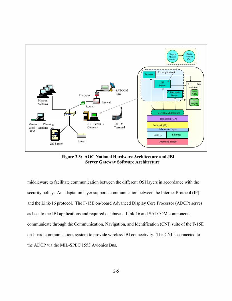
Figure 2.3 shows the JBI Server Gateway that includes the JBI Server application and it’s
related databases and associated collaboration applications. The above mentioned “Cup” or
mission fuselet resides on the JBI Server. In this scenario, CORBA serves as the distributed object
JBI Server Gateway
AWACS
Link-16 Nets
JBI Fusion Engine
306th Wing Air Operations Center
JBI Server
Link-16
Dist. Object Interface
JBI Client
Link-16
Dist. Object Interface
JBI Server
Link-16
Dist. Object Interface
Fuselet
Cup
Subscription / Publish
Figure 2.2: Linking the F-15E Aircraft into the JBI
F-15E
2-5
middleware to facilitate communication between the different OSI layers in accordance with the
security policy. An adaptation layer supports communication between the Internet Protocol (IP)
and the Link-16 protocol. The F-15E on-board Advanced Display Core Processor (ADCP) serves
as host to the JBI applications and required databases. Link-16 and SATCOM components
communicate through the Communication, Navigation, and Identification (CNI) suite of the F-15E
on-board communications system to provide wireless JBI connectivity. The CNI is connected to
the ADCP via the MIL-SPEC 1553 Avionics Bus.
Figure 2.3: AOC Notional Hardware Architecture and JBI Server Gateway Software Architecture
Mission Planning Work Stations w. DTM
JBI Server / Gateway
JTIDS Terminal
Mission Systems
JBI Server Printer
SATCOM Link Encryptor
Firewall Router
Browser
Imagery
ATO
JBI Data Resources
JBI Server
JBI Applications
Network (IP)
CORBA Middleware
Transport (TCP)
Link-16
Operating System
Ethernet
Adaptation Layer
Shogun Mission Fuselet
Shogun Mission
Cup
Collaboration Server

2-6
2.4 Information Assurance (IA) Capabilities.
IA functionality can be implemented in various components of the JBI—F-15E architecture.
Countermeasures are layered to provide “defense in depth”, where each layer provides it’s own
layer of security. Combined system security, then, is reinforced by each layer. For instance,
security could be deployed in the ground-based host systems, in the JBI network nodes, or on-
board the F-15E Strike Eagle. In focusing on the F-15E on-board notional architecture, there are
several areas where IA functionality can be implemented, such as:
• Real-Time Operating System: Trusted Security Kernel, Access Control
• Data Link Layer: Link-16/JTIDS Security and SATCOM Security
• IP Layer: IPSec/IPv6.0
• Middleware Layer: CORBASec
• Application/Transport Layer: SSL and/or Database Security
This research focuses on security implemented at the IP layer. It is assumed that IPv6 will be
used. IP Security (IPSec) is integrated into IPv6 and supports data origin, data integrity, data
confidentiality, replay protection and automated management of cryptographic keys [Kae99].
2.4.1 Security Threats and Countermeasures. When considering implementation of IA into
a communications system it is important to define threats and mechanisms available to counter
those threats. There are four types of security threats to consider along with their typical
countermeasures [TaV02]:
2-7
• Interception: This occurs when an unauthorized party gains access to data, such as
when a third party eavesdrops on a conversation by two other parties or when data is
illegally copied. A principle countermeasure to interception is data encryption.
• Interruption: Interruption occurs when data or services become unavailable, such as
when data is corrupted or lost. A typical example is a Denial of Service (DOS) attack
when a server can no longer be accessed because of overload. DOS is difficult to
defend against, but authorization countermeasures put in place through a firewall are
a typical method of protection
• Modification: Modification is the unauthorized changing of data or tampering with a
service so it no longer conforms to the original specification. An example is
tampering with database files or modifying the behavior of a program. Principle
counter measures include authentication, authorization, and/or auditing.
Authentication and authorization are put in place to prevent modification in the first
place whereas auditing is used to identify a perpetrator after-the-fact.
• Fabrication: Adding information to gain unauthorized access, such as replay attacks
or adding an entry into a password file are examples of fabrication. Similar to
protecting against the modification threat, authentication, authorization and auditing
provide a defense in this situation.
Some typical threats that might be encountered in the notional architecture include:
• Spoofing (modification): For example, communications from SATCOM to F-15Es can
be modified, such that an attacker attempts to introduce data packets that appear to
come from a trusted source. Countermeasures: TRANSEC and COMSEC of Airborne

2-8
Links and/or additional data encryption and packet source authentication mechanisms
at higher communication layers.
• Introduction of malicious software into an F-15E from the JBI can occur when an
adversary uses a JBI host to launch an attack against an F-15E. A typical situation is
where a hacker finds a backdoor into the JBI network (through Battlefield networks,
Defense Information System Networks, or the Internet) and creates a JBI object with
embedded malicious code payload. The corrupted JBI object is uploaded to the F-15E
aircraft via the Data Transfer Module (DTM), Link-16, or through SATCOM. The
malicious code can then execute its payload on-board the F-15E. Countermeasures:
Intrusion detection on-board the aircraft can mitigate the threat.
• Eavesdropping and/or Surveillance: This involves the unauthorized interception of
information. Successful attacks against airborne links requires the ability to thwart
TSEC and MSEC countermeasures at the data link level or the ability to monitor the
unencrypted messages at the source or destination nodes. Countermeasures: Data
encryption through TSEC and MSEC.
A comprehensive IA approach can be implemented by using a layered approach to security.
These layers need to: (1) protect the system from attacks through access control, firewalls, and
cryptography; (2) detect successful attacks (intrusions) through intrusion detection; (3) react to
attacks by terminating the attack, confining and deleting malicious software, restoring the system
to full integrity, notifying the pilot, WSO, and audit log.

2-9
2.5 Multi-Platform Common Data Link (MP-CDL)
MP-CDL provides a network-centric data link between airborne and surface Intelligence,
Surveillance, and Reconnaissance (ISR) assets. The MP-CDL program (contract awarded in
November 2002) is planned to meet the needs for a number of airborne and surface platforms to
simultaneously distribute sensor data products to multiple supporting airborne and ground
stations. MP-CDL is designed to meet the needs of various network clients (airborne and
surface) to interact with a centrally located airborne terminal as well as other clients.
All terminals will support gateway connectivity to other links external to the MP-CDL
network. These links may be either in-theater line-of-site (LOS) or beyond LOS such as
SATCOM links. The initial application of MP-CDL will be in support of Army surface units
command and control access to surveillance products from the Multi-Platform Radar Technology
Insertion Program (MP-RTIP) platform. In addition to network operations, the MP-CDL
terminals support the capability for point-to-point interoperability with CDL surface and/or
airborne terminals.
The requirement for a central airborne terminal is to provide a single point-to-point data
link operating simultaneously with an independent multi-user network. The terminal’s point-to-
point data link must be interoperable with exiting CDL surface communication equipment and
Airborne Information Transmission (ABIT) relay terminals at established standard data rates up
to 274 Megabits per second.
The multi-user network will connect up to 32 users on a COTS based network architecture.
Range will be dependent on size, weight, and power requirements and mission geometries to be
determined later, but is estimated to be approximately equal to the maximum LOS from an

2-10
altitude of 40,000 feet, or approximately 275-350 feet, depending on the height of the receiving
antenna near the earth’s surface. The MP-CDL system will operate in the Ku band and will
support future capability to operate in one or more alternative RF bands (i.e., X, Ku, Ka) to allow
multiple simultaneous links [PIX02].
The MP-CDL vision grew out of the MP-RTIP, which was originally a Joint STARS radar
upgrade. MP-RTIP was restructured in 2000 to develop a common modular scaleable radar in
three sizes:
• Large: Wide Area Surveillance (WAS)
• Medium: NATO
• Small: Global Hawk
2.5.1 MP-CDL Main Goals. The goals of MP-CDL are to provide:
• Transparent communication between deployed platforms [Cha02]
o IP based, per Global Grid Standards
o Low-latency, wideband path
o Common carrier for all types of traffic in IP packets
o Same HW/SW for air, ground, and sea
• A “LAN hub in the sky”
• Tradeoff Data rate vs. Antijam
2-11
• Common and COTS/GOTS Hardware
2.5.2 MP-CDL Data Rates. Throughput rates vary depending on the current
configuration of one-to-one communication devices such as AWACS to UAV, AWACS to
Common Ground Stations (CGS), UAV to CGSs. However, within the multi-user network, data
transmission rate capabilities are based on these minimum required rates.
The multi-user network data transmission rate from the central airborne terminal (host) to
the CGSs (clients) is:
• 45 Megabits per second unjammed to CGS
• 2.2 Megabits per second in jam resistant mode
• Similar rates from ISR hub for air-air net
The multi-user network data transmission rate capability from the CGSs (clients) to the
central airborne terminal (host) is:
• CGSs: low send data, limited power and antenna size. Will dynamically share a
low-rate up-link.
• A ground station with more bandwidth and a bigger dish could reach aircraft with
40-60 Megabits per second.
• ISR platforms should reach 20-40-60 Megabits per second air-air depending on
geography and dish size.

2-12
2.5.3 Standardization Issues. The DoD tactical message standard is TADIL-J (Link-16).
Non-tactical standard is IP. MP-CDL terminals will transmit and receive IP packets, and will not
be involved in the content, format, or protocol of the data (unless the packet is addressed to that
particular terminal). MP-CDL message sizes vary in length from 100 bits to 100 Mbits, and
message types and sensor data from the Air Force, Army and Navy, such as TADIL-J, Moving
Target Indicator (MTI), Synthetic Aperture Radar (SAR), Signals Intelligence (SIGINT), Air
Tasking Order (ATO), and Global Grid (GG).
2.6 IPSec/IPv6
IPSec, short for IP Security, is a set of protocols developed by the Internet Engineering
Task Force (IETF) to support secure exchange of packets at the IP layer [Kae99]. IPSec has
been deployed widely to implement Virtual Private Networks (VPN). IPSec is supported in IP
version 4 (IPv4) and is mandatory for the next generation of IP, version 6 (IPv6). IPSec supports
two encryption modes: Transport and Tunnel. Transport mode encrypts only the data portion
(payload) of each packet, but leaves the header untouched. The more secure Tunnel mode
encrypts both the header and the payload.
A compliant IPSec implementation must support the required set of Security Association
(SA) bundle types as outline in Section 4.5 of the Internet Engineering Task Force (IETF)
Request For Comments (RFC) 2401 [RFC 2401]. The bundle types include four different
combinations of the Authentication Header (AH) and Encapsulating Security Payload (ESP)
protocols. On the receiving side, a compliant device decrypts each packet. The compliant
protocol is designed to support these security areas:

2-13
• Data Origin Authentication
• Data Integrity
• Data Confidentiality
• Replay Protection
The Security Association (SA) concept is fundamental to IPSec. An SA is a relationship
between two or more entities that describes how the entities will use security services to
communicate effectively. The SA includes: an encryption algorithm; an authentication
algorithm; and a shared session key.
For a compliant IPSec implementation to work, sending and receiving devices must share a
public key. This is accomplished through a protocol known as Internet Security Association and
Key Management Protocol/Oakley (ISAKMP/Oakley), which allows the receiver to obtain a
public key and authenticate the sender using digital certificates [Kae99].
IPSec uses the AH protocol and ESP protocols to provide proof of data origin on received
packets, data integrity, anti-replay protection, data confidentiality and limited traffic flow
confidentiality. These two protocols can be combined and used to protect an entire IP datagram
or just the upper-layer protocols of the IP payload.
Besides support for mobility, security is a key requirement for the successor to today's
Internet Protocol version. Except for application-level protocols like SSL or SSH, all IP traffic
between two nodes can be transmitted without changing any applications. All applications on a

2-14
machine that benefit from encryption and authentication policies can be set on a per-host (or even
per-network) basis, not per application/service.
2.6.1 Authentication Header Protocol. Use of the AH protocol will increase the IP
protocol processing costs and will also increase the communications latency. The increased
latency is due to the additional authentication data contained in the AH. The fields of the AH as
shown in Figure 2-4 are explained as follows:
• Next Header – 8 bit field which identifies the type of the next payload after the AH
• Payload Length – 8 bit field which specifies the length of the AH in 32 bit words
• Reserved – 16 bit field which must be set to zero
• Security Parameters Index (SPI) – A 32 bit value that in combination with the
destination address identifies the SA for the datagram
• Sequence Number Field – Unsigned 32 bit field contains a monotonically increasing
counter value for defense against replay attacks
• Authentication Data – Variable length field that contains the Integrity Check Value
(ICV) for the payload
Next Header – 8 bits Payload Length – 8 bits Reserved – 16 bits
Security Parameters Index (SPI) – 32 bits
Sequence Number Field – 32 bits
Authentication Data – Variable Size
Figure 2.4: Authentication Header (AH) Format

2-15
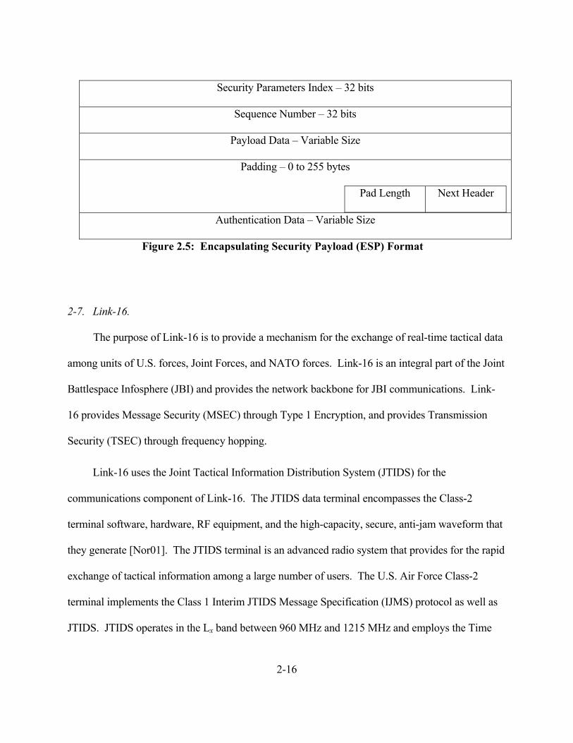
2.6.2 Encapsulating Security Payload Protocol. Use of the ESP protocol will also
increase processing costs and communication costs in a similar manner as the AH protocol. The
ESP header holds encryption, replay, and authentication information for its IP datagram. If
authentication is selected as part of the SA, encryption is performed first followed by
authentication. The encryption algorithm used is selected by the SA. ESP is designed to use
symmetric key encryption algorithms. The fields of the ESP header as shown in Figure 2-5 are:
• Security Parameters Index (SPI) – A 32 bit value that in combination with the
destination address identifies the Security Association for the datagram
• Sequence Number Field – Unsigned 32 bit field contains a monotonically increasing
counter value for defense against replay attacks
• Payload Data – Variable length field containing data described by the Next header
field. If the encryption algorithm requires an initialization Vector then that would be
contained here
• Padding (0-255 bytes) – May be required to satisfy requirements for encryption
algorithms
• Pad Length – Indicates the number of bytes used in the Padding field
• Next Header – Identifies the type of data contained in the Payload field
• Authentication Data – Variable length field that contains the Integrity Check Value
(ICV) for the packet
2-16
Security Parameters Index – 32 bits
Sequence Number – 32 bits
Payload Data – Variable Size
Padding – 0 to 255 bytes
Pad Length Next Header
Authentication Data – Variable Size
Figure 2.5: Encapsulating Security Payload (ESP) Format
2-7. Link-16.
The purpose of Link-16 is to provide a mechanism for the exchange of real-time tactical data
among units of U.S. forces, Joint Forces, and NATO forces. Link-16 is an integral part of the Joint
Battlespace Infosphere (JBI) and provides the network backbone for JBI communications. Link-
16 provides Message Security (MSEC) through Type 1 Encryption, and provides Transmission
Security (TSEC) through frequency hopping.
Link-16 uses the Joint Tactical Information Distribution System (JTIDS) for the
communications component of Link-16. The JTIDS data terminal encompasses the Class-2
terminal software, hardware, RF equipment, and the high-capacity, secure, anti-jam waveform that
they generate [Nor01]. The JTIDS terminal is an advanced radio system that provides for the rapid
exchange of tactical information among a large number of users. The U.S. Air Force Class-2
terminal implements the Class 1 Interim JTIDS Message Specification (IJMS) protocol as well as
JTIDS. JTIDS operates in the Lx band between 960 MHz and 1215 MHz and employs the Time

2-17
Division Multiple Access (TDMA) architecture. By using different frequencies, a technique called
“frequency hopping”, multiple nets can be “stacked” through the simultaneous use of time slots.
Each time slot is 7.8125 milliseconds in duration. JTIDS provides 51 different frequencies for
frequency hopping. The frequencies assigned to JTIDS for TDMA1 transmissions vary in range
from 969 MHz to 1206 MHz in 3 MHz increments. Each pulse is transmitted on a different
frequency in a pseudorandom pattern that depends on the net number and the TSEC crypto-
variable. The nominal frequency-hopping rate is greater than 33,000 hops per second [Nor01].
2.7.1 Data Exchange Rates. Link-16 can transmit either 3, 6, or 12 data words in a 7.8125
msec (1/128 sec) time slot depending on whether the Standard, Packed-2, or Packed-4 data packing
structure is used. Each Link-16 data word is made up of 75 bits, of which 70 bits are data, 4 are
used for parity and 1 is reserved as a spare bit. The effective tactical data rates of Link-16 are 26.88
kilo bits per second (kbps), 53.76 kbps, or 107.52 kbps, depending on the data packing structure
used. Each 7.1825 msec time slot of unencoded information holds 450 bits at Standard packing,
900 bits at Packed-2 packing, and 1800 bits at Packed-4 packing. Because error detection and
correction (EDAC) requires 16 bits for every 15 bits of data, the same time slot with Reed-
Solomon encoding only holds 210, 420, and 840 bits of tactical information for the Standard,
Packed-2, and Packed-4 encoding [Nor01].
1 Link-16 operates on the principle of Time Division Multiple Access (TDMA), wherein 128 time slots per second are allocated
among all participating JTIDS Units (JU) for the origination and reception of data.
2-18
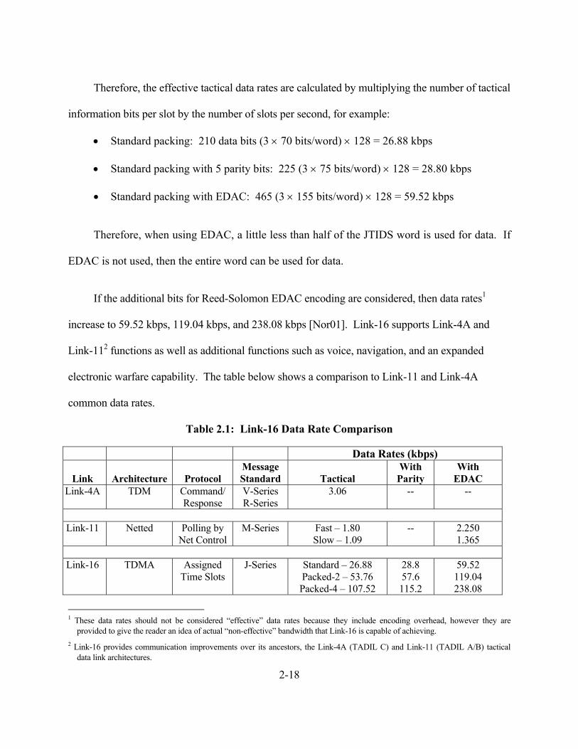
Therefore, the effective tactical data rates are calculated by multiplying the number of tactical
information bits per slot by the number of slots per second, for example:
• Standard packing: 210 data bits (3 × 70 bits/word) × 128 = 26.88 kbps
• Standard packing with 5 parity bits: 225 (3 × 75 bits/word) × 128 = 28.80 kbps
• Standard packing with EDAC: 465 (3 × 155 bits/word) × 128 = 59.52 kbps
Therefore, when using EDAC, a little less than half of the JTIDS word is used for data. If
EDAC is not used, then the entire word can be used for data.
If the additional bits for Reed-Solomon EDAC encoding are considered, then data rates1
increase to 59.52 kbps, 119.04 kbps, and 238.08 kbps [Nor01]. Link-16 supports Link-4A and
Link-112 functions as well as additional functions such as voice, navigation, and an expanded
electronic warfare capability. The table below shows a comparison to Link-11 and Link-4A
common data rates.
Table 2.1: Link-16 Data Rate Comparison
Data Rates (kbps)
Link
Architecture
Protocol Message Standard
Tactical
With Parity
With EDAC
Link-4A TDM Command/ Response
V-Series R-Series
3.06 -- --
Link-11 Netted Polling by
Net Control M-Series Fast – 1.80
Slow – 1.09 -- 2.250
1.365
Link-16 TDMA Assigned Time Slots
J-Series Standard – 26.88 Packed-2 – 53.76 Packed-4 – 107.52
28.8 57.6 115.2
59.52 119.04 238.08
1 These data rates should not be considered “effective” data rates because they include encoding overhead, however they are
provided to give the reader an idea of actual “non-effective” bandwidth that Link-16 is capable of achieving. 2 Link-16 provides communication improvements over its ancestors, the Link-4A (TADIL C) and Link-11 (TADIL A/B) tactical
data link architectures.
2-19
2.7.2 Link-16 Data Security. Link-16 encrypts both the message and the transmission.
Message security (MSEC) uses the KGV-8 encryption device and cryptovariables to encrypt
message traffic. Transmission security (TSEC) is also accomplished through the use of
cryptovariables, which control the JTIDS waveform. An important feature of the waveform is its
use of frequency hopping. The hopping pattern is determined by both the net number and the
TSEC cryptovariable. The TSEC cryptovariable also determines the amount of jitter in the
signal, and a predetermined, pseudorandom pattern of noise that is mixed with the signal prior to
transmission.
2-8. Common Object Request Broker Architecture (CORBA)
CORBA, considered to be the most widely-used middleware standard, is an industry-
defined specification for distributed systems. The CORBA specifications are a product of the
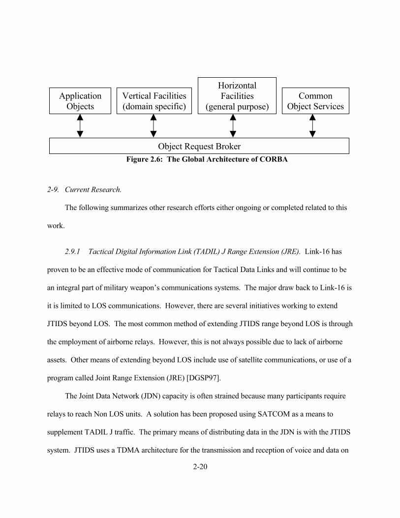
Object Management Group (OMG) [TaV02]. The global architecture (reference Figure 2.6) of
CORBA consists of four groups of architectural elements connected to what is call the Object
Request Broker (ORB).
The ORB forms the core of any CORBA distributed system and is responsible for enabling
communication between objects and their clients [Tav02]. In the notional architecture discussed
above, CORBA objects (Cups) may reside either in the JBI server or on-board the aircraft.
Security threats to CORBA objects may appear in the form of attackers attempting unauthorized
access to a CORBA object or unauthorized creation of a CORBA object. Countermeasures
include the use of ORBs, which fully support the CORBA Security (CORBASec) specification,
at the CORBA middleware level of the notional architecture as shown in Figure 2.6.
2-20
Figure 2.6: The Global Architecture of CORBA
2-9. Current Research.
The following summarizes other research efforts either ongoing or completed related to this
work.
2.9.1 Tactical Digital Information Link (TADIL) J Range Extension (JRE). Link-16 has
proven to be an effective mode of communication for Tactical Data Links and will continue to be
an integral part of military weapon’s communications systems. The major draw back to Link-16 is
it is limited to LOS communications. However, there are several initiatives working to extend
JTIDS beyond LOS. The most common method of extending JTIDS range beyond LOS is through
the employment of airborne relays. However, this is not always possible due to lack of airborne
assets. Other means of extending beyond LOS include use of satellite communications, or use of a
program called Joint Range Extension (JRE) [DGSP97].
The Joint Data Network (JDN) capacity is often strained because many participants require
relays to reach Non LOS units. A solution has been proposed using SATCOM as a means to
supplement TADIL J traffic. The primary means of distributing data in the JDN is with the JTIDS
system. JTIDS uses a TDMA architecture for the transmission and reception of voice and data on
Object Request Broker
Vertical Facilities (domain specific)
Horizontal Facilities
(general purpose)Application
Objects Common
Object Services

2-21
a finite number of time slots. When relays are needed to reach NLOS units, the number of time
slots is doubled for that particular operation.
The TADIL J JRE program proposes a possible solution to the relay problem. The program
is being conducted in three phases. The Phase 1 demonstration is a simple check to see if TADIL-J
messages could be sent through a satellite and received within the required TMD latency. Phase 1
was successful and demonstrated that TADIL-J messages could be relayed through a satellite in
near real time. Phase 2 of JRE was similar to Phase 1 but the data was passed through a STU-III
before it was reformatted into a J3.6 message before being sent via SATCOM. Phase 2 also
proved successful. Phases 1 and 2 were conducted without using JTIDS terminals or networks.
The Phase 3 demonstration connected remote JTIDS networks through the satellite range
extension. The Phase 3 demonstration was also successful and demonstrated there was a potential
savings of time slots on the JDN utilizing the JRE. JRE also provides more reliable connectivity in
hostile environments because airborne assets might not be available.
2.9.2 ATM Network-Based Integrated Battlespace Simulation With Multiple UAV-AWACS-
Fighter Platforms. This research provides a realistic input to the amount of throughput that is
required to support realistic C4I applications, real time battle management, SAR image processing
and analysis, and real time air tasking order (ATO) monitoring through the demonstration of an
integrated battlespace simulation on an advanced AWACS prototype network. The integrated
battlespace simulation includes the unmanned aerial vehicle (UAV), C4I platform, and fighter
aircraft as core battlefield components. The simulation uses a scenario not unlike the scenario
introduced at the beginning of this chapter. For its demonstration it uses both ATM LAN
emulation and classical IP over ATM multicast configurations.
2-22
ATM Classical IP-based (CIP) Multicast Solution: The ATM CIP protocol lacks a broadcast
mechanism. This is resolved by setting up point-to-multipoint permanent virtual circuit (PVC)
connections from a broadcast server to all clients. Since there is no such server in CIP, creation of
a virtual broadcasting node (that corresponds to a broadcast service access point) at the switch is
necessary.
ATM LAN Emulation-based Multicast Solution: ATM LAN emulation can support multiple
independent emulated LANs (ELANs), and the membership in any of the ELANs is independent
of the physical location of the end system. The AWACS mission computer must be a member of
all ELANs so that it can selectively broadcast information to any of the AWACS, fighter, or UAV
group as different multicast groups.
The maximum throughput in the TCP stream test was 108 Mbps for the ATM LAN
emulation solution and 118 Mbps for the ATM CIP solution. As long as the socket buffer sizes
were kept above 64 Kilobytes, then both solutions demonstrated normal operation.
2.9.3 IP Mobility Management for the Airborne Communications Node (ACN) Platform.
In network-centric architecture where data is transferred via IP packets, it is important to consider
issues that occur when moving from one ACN to another. These include: average signal strength;
subscriber mobility as they move from one footprint of an ACN to another; and other types of
mobile subscribers. A potential problem occurs when, for example, an entire brigade moves
relative to the ACN, into the footprint of another ACN. Mobility management must ensure that
routing to and from the edge routers continues to operate correctly. One solution is Mobile IP, an
IETF protocol designed to handle IP mobility [RFC 2002]. However, the range of movements of
2-23
the edge routers will be restricted to within the ACN network domain. Therefore, only small-scale
mobility management is required and an alternative to the Mobile IP solution can be considered
such as a dynamic routing table update solution. Link state routing performed better than the
mobile IP solution in terms of overhead and does not have a single point of failure (as in Mobile IP
with its home agent) [JaW00]. Although security overhead was not considered, other overhead
issues were which may be beneficial when considering security overhead [JaW00].
2.9.4 Surveillance and Control Data Link Network (SCDLN) for Joint STARS. The Joint
Surveillance and Target Attack Radar System (Joint STARS) communications systems is used to
connect an airborne radar platform and many mobile Ground Station Modules (GSM) [SaB94].
The SCDLN uses a secure, highly jam-resistant, dynamically alterable two-way digital data link
for the control and distribution of information. The SCDLN has an additional capability to provide
an autonomous message communication network over a wide aerial coverage in a hostile
environment. The major contributor to the anti-jam performance is the Fast Frequency Hopping
(FFH) spread spectrum waveform. Of particular interest in this article is the network architecture.
Messages are transmitted in packets and the format will support the transfer of TADIL-J (JTIDS)
packet messages.
The network is configured so that an airborne platform retransmits incoming data from any
GSM back to another or multiple GSMs within the local theatre of operations. The network
operates in half-duplex mode where time is divided into bursts, each burst lasting for 100
milliseconds. The downlink operation (from airborne platform to GSM) occupies approximately
half this time, and two independent uplinks plus a guard time occupy the other half. The
retransmittal of the uplink message becomes an automatic acknowledgement to the sending GSM

2-24
that the uplink message was correctly received at the AWACS and also allows addressing
information to any other GSM in the network (or all of them). An unlimited number of GSMs can
copy both downlink sensor data and relayed messages. However, a maximum of 15 GSMs can be
active at any time and participate in transmitting uplink messages. Any GSM or AWACS can be
the master in the network at a given time. GSMs are allowed to enter or depart from the network.
Once the AWACS commences downlink transmission, an initial polling sequence begins and the
network is established by each GSM searching independently for the AWACS downlink signal and
once found, begins downlink tracking.
2-10. Summary.
This chapter provides a general background and literature review for this research. A
notional JBI architecture was presented and how Link-16 fits into the overall JBI scenario was
discussed. Of particular interest are IA issues within the JBI and the best approach to establishing
a robust IA security within the Link-16 arena through the use of IPv6 and IPSec. Other approaches
were considered through the use of CORBA security using objects to control access rights.
3-1
III. Methodology
3.1 Problem Definition.
As communications technologies have developed, military systems have migrated from
stand-alone systems to client-server and fully networked systems. Therefore, more stringent
security requirements have resulted in increased demands on security mechanisms. The
integration of embedded systems such as the F-15E within the proposed Joint Battlespace
Infosphere (JBI) network topology exposes this aircraft to new information warfare threats.
Exacerbating the problem, information assurance technologies designed for use in real-time
embedded systems have not kept pace with emerging threats [Ray01]. Link-16 is a prime
candidate to provide a network backbone for the proposed JBI communications. The Joint
Tactical Information Distribution System (JTIDS) terminal, which makes up the communications
component of Link-16, provides Message Security (MSEC) through data encryption and
Transmission Security (TSEC) through frequency hopping. However, further security can be
implemented through the network layer of the communications architecture.
3.1.1 Goals and Hypothesis. The research goal is to evaluate the performance of an
Information Assurance scheme that incorporates IPv6 and IPSec over a Link-16 datalink
network. This goal is further defined by the following sub-goals:
1. Evaluate the performance metrics of a baseline Link-16 system that incorporates
IP packets across the Link-16 network.
2. Determine the impact of incorporating IPSec into the baseline system.
3. Determine the impact of various offered loads to the baseline system.
3-2
It is hypothesized that IPv6 and/or IPSec can be incorporated into the Link-16 network
without degrading performance to a level that it is incapable of supporting real-time data and
voice transmission.
3.1.2 Approach. To accomplish the above stated goals, a Link-16 model was used with
the OPNET network simulation software to simulate IP traffic over a Link-16 network. A
distributed software system was used in which an external model communicates with the
OPNET software to simulate incoming JBI traffic fed to the Link-16 network. This system
provided the necessary model to compare IP baseline traffic to IPSec to determine effects of
increased load on the Link-16 network.
3.2 System Boundaries.
The System Under Test (SUT), Figure 3.1, includes the F-15E JBI Connectivity Software
Architecture. This includes the Real-Time OS, the Physical Layer (Link-16), an Adaptation
Layer, the Network (IP) Layer, the Transport (TCP) Layer, Real-Time CORBA Middleware, and
the JBI applications. Also included but not pictured in Figure 3.1 is the JTIDS terminal, the
communications component used to transmit data and voice transmissions across the Link-16
network. Not included in the SUT are the other components of the F-15E Avionics System
Architecture which include Intelligence, Sensors, and Radar (ISR) collecting components.
Within the SUT, the Component Under Test (CUT) includes the JTIDS terminal, the Physical
Layer (Link-16), the Adaptation Layer, the Network Layer (IP), and the Transport Layer (TCP).

3-3
Figure 3.1: F-15E JBI Connectivity Software Architecture [Ray01]
3.3 System Services.
The network layer decouples upper layers with independence from the data transmission
and switching technologies used to connect systems. In addition, the network layer provides
network security including security services at the IP layer of the TCP/IP protocol stack. The set
of security services IPSec can provide includes data origin authentication, data integrity,
confidentiality (encryption), and rejection of replayed packets (a form of partial sequence
integrity), and limited traffic flow confidentiality. All of these services are provided at the IP
Network (IP)
JTIDS Control
Transport (TCP)
Link-16
Real-Time OS
SATCOM
JBI Client
JBI Data Resources
Browser
Resource Management
JBI Applications
CollaborationClient
RT CORBA MIDDLEWARE
Adaptation Layer
3-4
layer and can be used by any higher layer protocol such as TCP and UDP [Kae99]. The primary
services for this study and their possible outcomes include:
1. Data Origin Authentication.
a. Success – Packet received from valid origin (packet accepted)
b. Failure – Unable to establish that packet came from valid origin (packet
dropped)
2. Data Integrity, Data Confidentiality.
a. Success – Packet payload has not been tampered with (packet accepted)
b. Failure – Unable to establish that packet payload can be trusted (packet
dropped)
3. Replay Protection.
a. Success – Packets are prevented from being resent from an unauthorized
source therefore preventing unauthorized access (packet dropped)
b. Failure – Unable to detect that a packet came from an unauthorized source
(packet accepted)
3.4 Performance Metrics.
The following metrics are used:
1. Throughput – Throughput is defined as Transfer Size/Transfer Time, where Transfer
Size is measured in bits and Transfer Time is measured in seconds. Transfer Size is
defined to be number of tactical data bits, thus does not include Reed-Solomon
encoding. The effective tactical data rates of Link-16 vary depending on the data
packing structure used.
3-5
2. End-to-End (ETE) delay – ETE is measured in seconds and is defined to be the elapsed
time from when a packet arrives at the source node’s routing layer to when the packet is
received by the routing layer of the destination node.
3. Data transfer – In Link-16, either 3, 6, or 12 Link-16 words can be transmitted in a
7.8125 msec time slot depending on whether the Standard, Packed-2, or Packed-4 data
packing structure is used. For instance if the Packed-2 packing structure is used, then
420 (six 70-bit words) data bits are transferred in 1/128 second to give an instantaneous
rate of 52.5 kbps.
3.5 Parameters.
Within the system boundaries, the system and workload parameters that affect performance are
defined below.
3.5.1 System Parameters.
1. JTIDS Transmission/Reception Equipment – This equipment is the
communications component of Link-16. It encompasses the Class 2 terminal
software, hardware, RF equipment, and the high-capacity, secure anti-jam
waveform that they generate [Nor01].
2. JBI Applications – These include the JBI server, browser, and collaboration
server.
3. JBI Data Resources – These include Air Tasking Orders, Imagery, etc.
4. Network Layers – TCP, IP, physical layer.
5. RT CORBA Middleware – Intermediary for passing objects between TCP layer
and JBI applications.
3-6
3.5.2 Workload Parameters.
1. Data rate – The tactical data rate range for Link-16 is 28.80 kbps to 115.20
kbps.
2. Voice and data workload – A trace of traffic measured on a real-time system
will be used to compare against simulated results. Data includes tactical data
information such as navigation waypoints, target assignment, target tracking,
release points, munitions inventory, and sensor data.
3. IPv6 versus IPSec – IPv6 provides the channel for transferring IP packets.
IPSec provides the additional security measures required for multi-level security
within the F-15E notional architecture.
4. Operating System (OS) – Proprietary real-time OS versus COTS.
5. Packing structure – Either Standard, Packed-2, or Packed-4 data packing
structure is used.
3.6 Factors.
The following factors and their corresponding levels were chosen as the most significant
for this research.
3.6.1 Data rate.
1. Standard Tactical Rate (with parity) – 28.8 kbps
2. Packed-2 Tactical Rate (with parity) – 57.6 kbps
3. Packed-4 Tactical Rate (with parity) – 115.2 kbps
3.6.2 Internet Protocol.
1. IPv6 – This provides a baseline performance analysis of IP packets over
Link-16.
3-7
2. IPSec – Additional overhead from IPSec is considered to determine if the
Link-16 network can handle the increased workload. The two protocols of concern
are the Authentication Header protocol and the Encapsulated Security Payload
protocol
3.7 Evaluation Technique.
An OPNET Link-16 model developed by the Navy Space and Naval Warfare
(SPAWAR) Systems Command office is used to evaluate this performance analysis. Some
modifications to the model were made by the Air Force Research Lab (AFRL) Sensors
Directorate. An external mission model was used with the OPNET Link-16 model to input
mission data such as message type, message ID, message size, source, and destination.
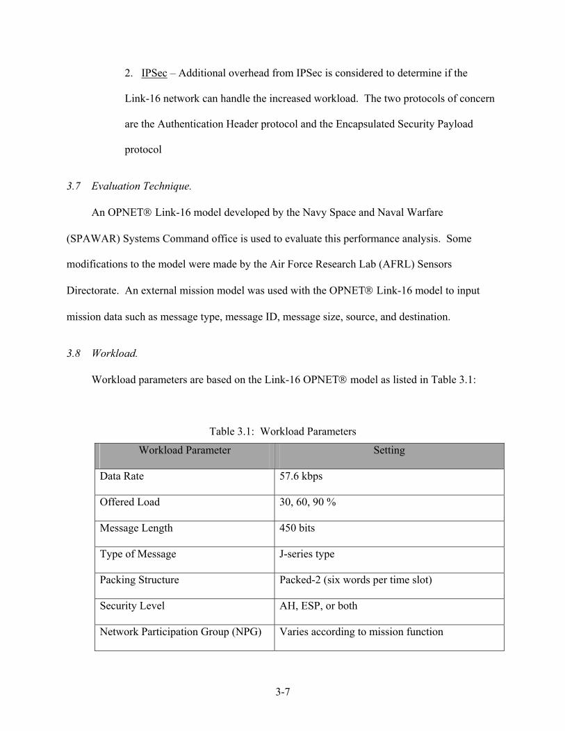
3.8 Workload.
Workload parameters are based on the Link-16 OPNET model as listed in Table 3.1:
Table 3.1: Workload Parameters
Workload Parameter Setting
Data Rate 57.6 kbps
Offered Load 30, 60, 90 %
Message Length 450 bits
Type of Message J-series type
Packing Structure Packed-2 (six words per time slot)
Security Level AH, ESP, or both
Network Participation Group (NPG) Varies according to mission function

3-8
3.9 Experimental Design.
This experimental design consists of specifying the number of experiments, the factor level
combinations for each experiment, and the number of replications of each experiment. Since this
experiment included one factor with three levels and another factor with three levels, there were
3 × 3 = 9 experiments. Five replications were conducted for a total of 5 × 9 = 45 simulations.
The 30%, 60%, and 90% offered load levels were chosen to show the effects these loads have on
the Link-16 network when its lightly loaded, moderately loaded, and heavily loaded. Although
three different security levels were chosen (AH, ESP, and a combination of AH and ESP), it was
not necessary to repeat a full set of simulations for the ESP level since it only adds two more
bytes of overhead to the IP packet and the difference in the simulation results was negligible.
Therefore, a few simulations were run to verify that the difference was negligible when adding
26 bytes of overhead from the AH extension versus adding 28 bytes of overhead from the ESP
extension.
3.10 Summary.
This chapter described the methodology to be used for the performance analysis of
implementing IP packets over the Link-16 network. It discussed the thesis goal, approach to be
used, system boundaries and services, performance metrics, parameters, factors, and workload.
4-1
IV. IMPLEMENTATION AND ANALYSIS
4.1 Overview
This chapter provides research results and analysis. The verification and validation of the
OPNET implementation of the Link-16 model is described and a description of the baseline IPv6
over Link-16 model is presented. For comparison to the baseline, security features are added to
IPv6 to further test the Link-16 network’s capacity to handle increased demand. Finally, this
chapter provides an overview of results and overall analysis.
4.2 Link-16 Verification and Validation
OPNET is a Commercial Off-The-Shelf (COTS) program that provides an environment for
network simulations. It is widely used throughout the DoD for network modeling and provides
support for detailed radio modeling, which is a key requirement for JTIDS. OPNET’s network
traffic is generated stochastically, using probability density functions. Therefore, generated data
packets do not contain information, but are just tokens that represent data of a given size that
transverse a given network. This is sufficient for this study, since we are only interested in how
overhead and data load affect overall performance, the particular information contained in packets
is irrelevant. The model need is based on a model provided by the AFRL Sensors Directorate and
uses OPNET’s radio propagation model, referred to as the Radio Transceiver Pipeline, and
simulates the protocol message packet and models a JTIDS terminal’s transmissions on a time slot
basis. Figure 4.1 shows the communications system consisting of an external mission model, and
the JTIDS hosts and JTIDS terminals used in the Link-16 model. The mission model is used to
communicate with the Link-16 model and provides the offered load and mission data to the Link-
16 network.

4-2
Figure 4.1: Mission Model – Link-16 Communication System
This OPNET model was configured using the Link-16, Packed-2 packet format, which
contains two 3-word blocks of 225 bits each for a total of 450 bits. For example, one particular test
sent 2160 bytes (17,280 bits) from a Narrow Area Search Munitions (NASM) terminal to the
Airborne Command and Control Center (ABCCC) terminal. The 17,280 bits were divided up and
inserted into 39 (17,280/450 = 38.4) JTIDS packets.
The JTIDS transmitter terminal adds 35 bits of overhead to the 6-word JTIDS packet for a
total of 485 bits. Average data rate is calculated based on 450 bits transmitted every 1/128th of a
second, therefore 450 × 128 = 57,600 bps. The terminal model supports transmission and
reception of free-text format messages, the format used to transmit IP packet data through the
Link-16 network. The terminal model is a simplified representation of a JTIDS terminal that
enqueues incoming TADIL-J messages from the host into available buffers, and sends them out in
the correct timeslot. The terminal model uses the OPNET Radio Transceiver Pipeline to
calculate the effects of Radio Frequency (RF) propagation. The pipeline stages used are modified
versions of the default radio pipeline stages provided by OPNET. The modifications allow for
Mission Model

4-3
improved bit error rate calculation and add support for animation of the radio links. The host-to-
terminal interface is represented as a duplex point-to-point link with zero delay. Although it is not
representative of the 1553 bus, the latency is factored into the Link-16 model.
JTIDS scenarios require the terminal nodes and host computer pairs to be co-located in
subnets for proper spatial movement. This organization is imposed by OPNET because node
models connected by physical links (as the terminal and host are by the dls_serial link) cannot be
mobile.
Figure 4.2 shows the OPNET host node model used to generate J-series messages, which
are sent to the JTIDS terminal shown in Figure 4.3.
Figure 4.2: dls_JTIDS_host Node Model

4-4
Figure 4.3: dls_radio_JTIDS Node Model
This J-series message packet format represents a single TADIL-J message consisting of six
75-bit words. The JTIDS terminal accepts these packets through the point-to-point serial interface
connecting it to the host computer. The JTIDS terminal encapsulates one or more TADIL-J
messages that are sent in the time slot, along with the message headers. The number of messages
encapsulated is dependent on the packing type and the length of each TADIL-J message, which in
the case of this model uses the Packed-2 format with a message length of 450 bits.
Validation was not accomplished on this model because no real-time data could be obtained
to validate the results against.
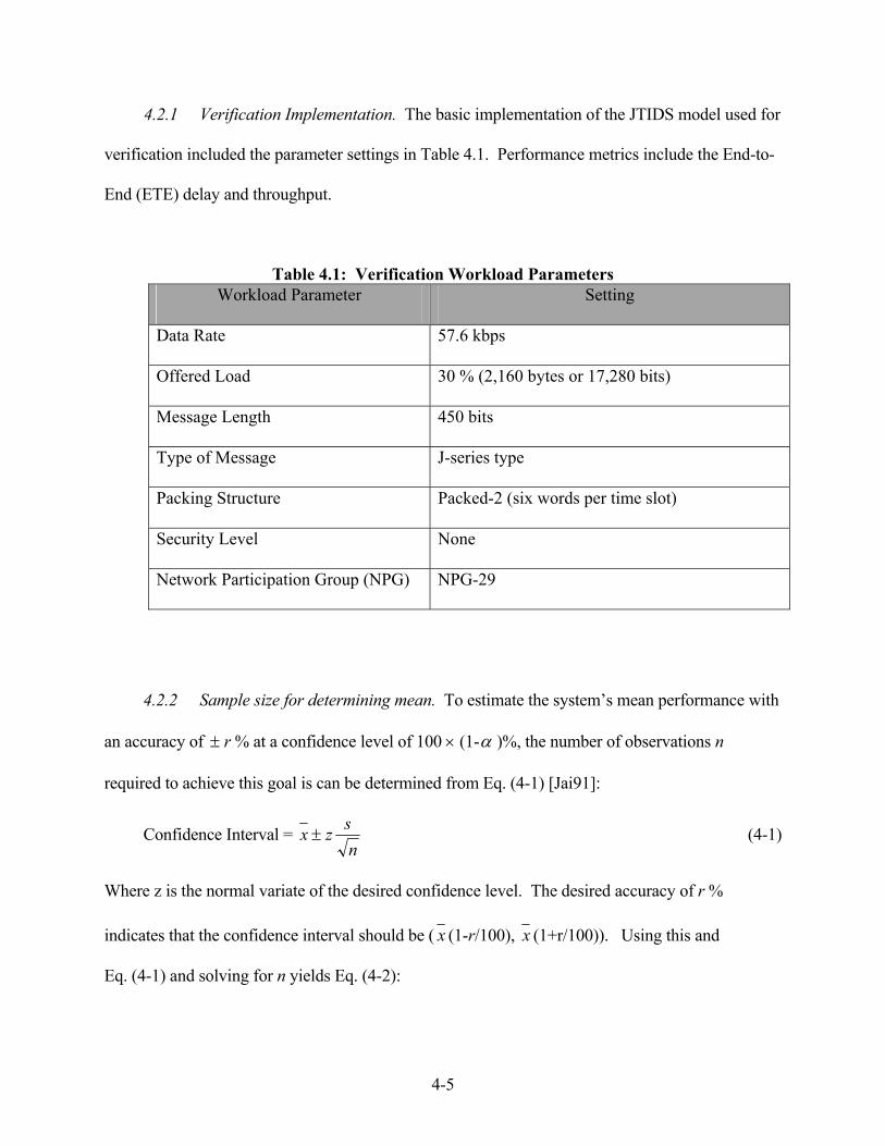
4-5
4.2.1 Verification Implementation. The basic implementation of the JTIDS model used for
verification included the parameter settings in Table 4.1. Performance metrics include the End-to-
End (ETE) delay and throughput.
Table 4.1: Verification Workload Parameters Workload Parameter Setting
Data Rate 57.6 kbps
Offered Load 30 % (2,160 bytes or 17,280 bits)
Message Length 450 bits
Type of Message J-series type
Packing Structure Packed-2 (six words per time slot)
Security Level None
Network Participation Group (NPG) NPG-29
4.2.2 Sample size for determining mean. To estimate the system’s mean performance with
an accuracy of ± r % at a confidence level of 100 × (1-α )%, the number of observations n
required to achieve this goal is can be determined from Eq. (4-1) [Jai91]:
Confidence Interval = nszx ± (4-1)
Where z is the normal variate of the desired confidence level. The desired accuracy of r %
indicates that the confidence interval should be ( x (1-r/100), x (1+r/100)). Using this and
Eq. (4-1) and solving for n yields Eq. (4-2):

4-6
2100
=
xrzsn
(4-2)
With an accuracy of 5 % and based on preliminary tests, each set of simulations requires
runs. Refer to Appendix D for calculations used to determine the required number of simulations.
4.2.3 Verification Results. The Link-16 OPNET model was verified by presenting data at
the host terminal and ensuring the data went across the host terminal to the sending JTIDS
transmitter terminal, then to the receiving JTIDS terminal, and finally to the receiving host
terminal. During this process, the number of bytes received at the receiving JTIDS terminal was
compared against the number of bytes sent at the sending JTIDS terminal to ensure that they were
equal.
The ETE delay was measured and compared against the ideal ETE delay. For instance,
when sending 17,280 bits through the network with the data rate set at 57,600 bits per second,
the ETE delay should be 17,280 bits/57,600 bps = 0.300. To verify the ETE delay, a
MATLAB program (cfi, Appendix E) was used to create exponentially distributed IP messages
at a frequency of 17,280 bps (2,160 bytes per second) for the baseline model representing a 30 %
offered load.
The MATLAB software program was used to create a script file that was input into an
external “mission model”. The mission model and the OPNET Link-16 model make up a
distributed system in which the mission model uses the script file to input mission data to the
OPNET Link-16 model. It includes the following types of data: type of message sent, time
message was transmitted, message ID, source ID, destination ID, and message quality.
Originally, messages were sent based on a deterministic distribution, or in other words the
5≤n

4-7
messages were sent every second with exactly one second between transmittals. However, this
method didn’t provide a realistic model of how traffic arrives at a network node and multiple
runs generated the same results each time. Therefore, an exponential distribution was created in
order to model the bursty nature of network traffic arriving at a node.
Through several simulations it was determined the OPNET model reached steady-state after
3000 samples were run, as shown in Figure 4.4. The average ETE delay was just over 0.250
seconds. Although the average ETE delay is typically expected to be equal to, or greater than,
the ideal ETE delay, the reason it is less can be explained by either one of, or a combination of
the following:
Figure 4.4: Average ETE Delay (2160 Byte Packet, 3000 Samples)
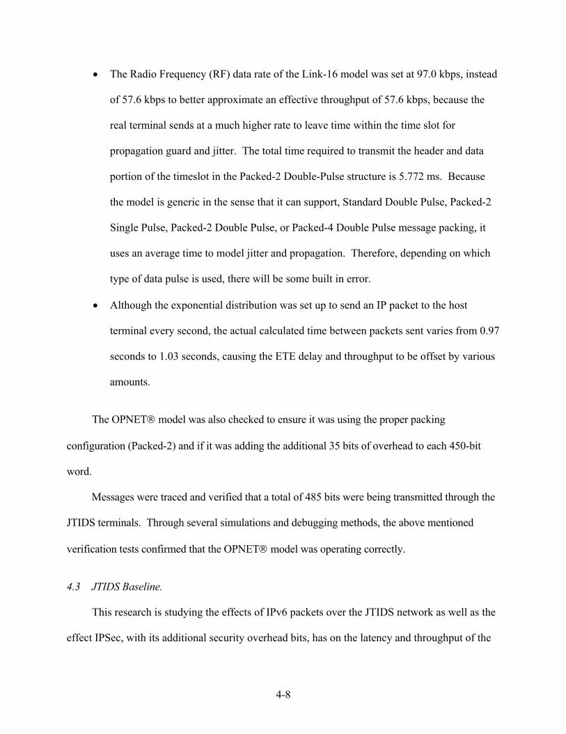
4-8
• The Radio Frequency (RF) data rate of the Link-16 model was set at 97.0 kbps, instead
of 57.6 kbps to better approximate an effective throughput of 57.6 kbps, because the
real terminal sends at a much higher rate to leave time within the time slot for
propagation guard and jitter. The total time required to transmit the header and data
portion of the timeslot in the Packed-2 Double-Pulse structure is 5.772 ms. Because
the model is generic in the sense that it can support, Standard Double Pulse, Packed-2
Single Pulse, Packed-2 Double Pulse, or Packed-4 Double Pulse message packing, it
uses an average time to model jitter and propagation. Therefore, depending on which
type of data pulse is used, there will be some built in error.
• Although the exponential distribution was set up to send an IP packet to the host
terminal every second, the actual calculated time between packets sent varies from 0.97
seconds to 1.03 seconds, causing the ETE delay and throughput to be offset by various
amounts.
The OPNET model was also checked to ensure it was using the proper packing
configuration (Packed-2) and if it was adding the additional 35 bits of overhead to each 450-bit
word.
Messages were traced and verified that a total of 485 bits were being transmitted through the
JTIDS terminals. Through several simulations and debugging methods, the above mentioned
verification tests confirmed that the OPNET model was operating correctly.
4.3 JTIDS Baseline.
This research is studying the effects of IPv6 packets over the JTIDS network as well as the
effect IPSec, with its additional security overhead bits, has on the latency and throughput of the
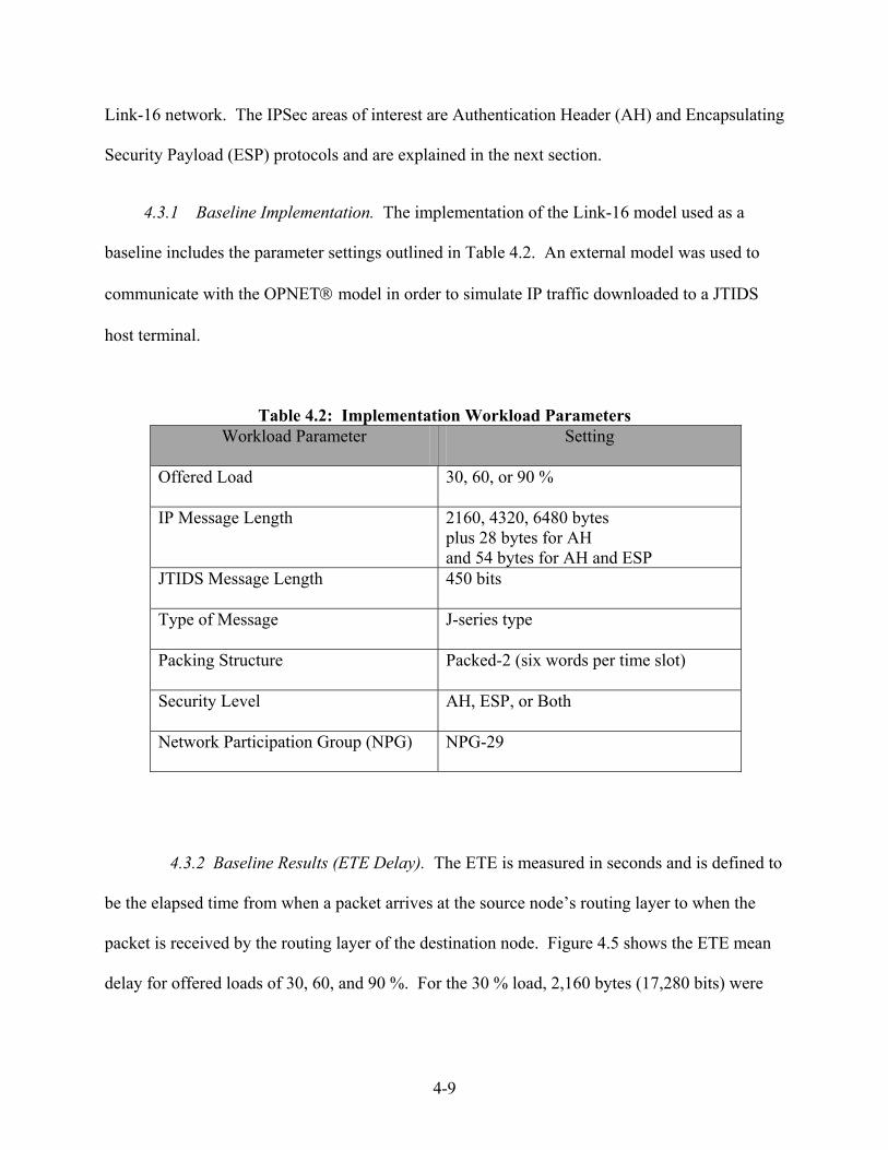
4-9
Link-16 network. The IPSec areas of interest are Authentication Header (AH) and Encapsulating
Security Payload (ESP) protocols and are explained in the next section.
4.3.1 Baseline Implementation. The implementation of the Link-16 model used as a
baseline includes the parameter settings outlined in Table 4.2. An external model was used to
communicate with the OPNET model in order to simulate IP traffic downloaded to a JTIDS
host terminal.
Table 4.2: Implementation Workload Parameters Workload Parameter Setting
Offered Load 30, 60, or 90 %
IP Message Length 2160, 4320, 6480 bytes plus 28 bytes for AH and 54 bytes for AH and ESP
JTIDS Message Length 450 bits
Type of Message J-series type
Packing Structure Packed-2 (six words per time slot)
Security Level AH, ESP, or Both
Network Participation Group (NPG) NPG-29
4.3.2 Baseline Results (ETE Delay). The ETE is measured in seconds and is defined to
be the elapsed time from when a packet arrives at the source node’s routing layer to when the
packet is received by the routing layer of the destination node. Figure 4.5 shows the ETE mean
delay for offered loads of 30, 60, and 90 %. For the 30 % load, 2,160 bytes (17,280 bits) were
4-10
generated every second for an average ETE delay of 0.256 seconds. The ideal ETE mean delay
should be 17,280 bits/57,600 bps = 0.300 seconds.
The 60 % offered load (4320 bytes) resulted in an average ETE of 0.652 seconds. The 90
% workload (6,480 bytes) resulted in an average ETE of 1.354 seconds. Additional simulations
were run using 8,000 byte IP packets at which point the ETE average was 2.506. As expected,
an increase in the number of bytes per second beyond the 90 % offered load caused the buffer to
backup, and required several hours for the OPNET simulations to reach completion.
End-To-End Delay (Baseline)
30
60
90
0.000
0.200
0.400
0.600
0.800
1.000
1.200
1.400
1.600
Offered Load (%)
ETE
Del
ay (s
econ
ds)
Figure 4.5: Baseline End-To-End Delay
4.3.3 Baseline Results (Effective Throughput). Figure 4.6 shows the effective throughput for
nominally offered loads of 30, 60, and 90 %. Effective throughput was calculated by using the
total number of bits offered at the host terminal divided by the total simulation time. The total

4-11
number of bits only includes the data bits, and does not include any overhead bits. The actual
offered load varied slightly from the nominally offered load. For instance, the 30 % offered load
should present 17,280 bits per second (bps) (57,600 × 0.30) to the host terminal. However, as
mentioned above, the exponential distribution is used to calculate the time each IP packet is
presented to the host terminal, but the actual calculated value for how often packets are presented
may differ from the nominal valued by as much as several milliseconds. As was the case in the
30 % offered load, the actual distribution time was 17,280 bits per 1.02 seconds. Therefore the
actual offered load was 16,941 (17,280/1.02). The measured effective throughput of 16,949 bps
is slightly different due to rounding errors in the Link-16 model.
Effective Throughput (Baseline)
30
60
90
0
10000
20000
30000
40000
50000
60000
Offered Load (%)
Thro
ughp
ut (b
ps)
Figure 4.6: Effective Throughput – Baseline

4-12
At the 60 % nominally offered load level the Link-16 network is only receiving 34,491 bps
and is not fully utilized and there is less chance of messages backing up in the buffer. However,
at the 90 % workload level, the host terminal is receiving 51,798 bps, which is near its maximum
capacity and messages back up in the buffer more frequently, thereby negatively impacting the
effective throughput and thus explains the super-linear growth.
4.4 JTIDS Security Feature Additions (IPSec)
Security and privacy in IPSec is integrated into IPv6 and provided through the AH and ESP
protocols.
4.4.1 Authentication Header (AH) Protocol – End-To-End Delay. The addition of the
AH to the IPv6 baseline involves using the keyed MD-5 hash function, or any one way hashing
algorithm to compute a 128-bit digest of the message to be transmitted [CDK01]. In this effort,
the MD-5 has function is considered for calculating additional overhead bits. The 128 bits
returned from the hash function is appended to the authentication data contained in the AH. As
mentioned in Chapter Two, the AH adds on 12 bytes from the first five fields of the AH and
another 16 bytes (128 bits) of authentication data for a total of 28 additional bytes added to the IP
packet. Therefore, even though this process requires extensive computer preprocessing, it only
adds 28 bytes of overhead to the baseline IP packet, thus effecting network latency and ETE
delay very minimally as shown in Figure 4.7 [Kae99].
4.4.2 Authentication Header (AH) Protocol -- Effective Throughput. Figure 4.8 shows
the effective throughput for offered loads of 30, 60, and 90 %. Similar to the ETE delay, the
effective throughput is minimally impacted due to the addition of the AH protocol.
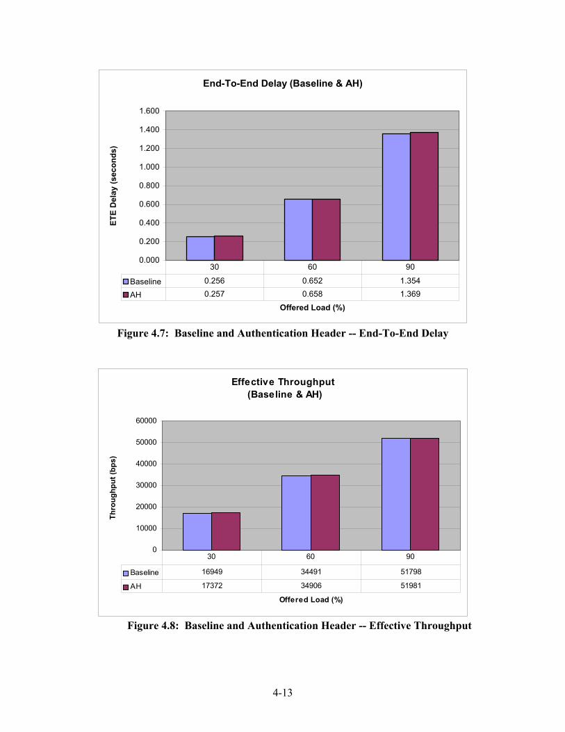
4-13
End-To-End Delay (Baseline & AH)
0.000
0.200
0.400
0.600
0.800
1.000
1.200
1.400
1.600
Offered Load (%)
ETE
Del
ay (s
econ
ds)
Baseline 0.256 0.652 1.354
AH 0.257 0.658 1.369
30 60 90
Figure 4.7: Baseline and Authentication Header -- End-To-End Delay
Effective Throughput (Baseline & AH)
0
10000
20000
30000
40000
50000
60000
Offered Load (%)
Thro
ughp
ut (b
ps)
Baseline 16949 34491 51798
AH 17372 34906 51981
30 60 90
Figure 4.8: Baseline and Authentication Header -- Effective Throughput

4-14
4.4.3 Encapsulating Security Payload (ESP) Protocol – Effective Throughput. The
addition of the ESP header to the IPv6 baseline uses an encryption algorithm to secure the
payload. A common encryption algorithm used is triple DES. Triple DES uses a 112-bit key to
encrypt the payload data, therefore adding 14 bytes onto the payload data. As described in
Chapter Two, the ESP protocol adds a minimum of 12 bytes and up to an additional 255 bytes (if
required by the encryption algorithm). A total of 26 bytes will be used as additional overhead
data for the ESP protocol.
Since the additional 28 bytes of overhead from the AH had such a small effect on the
overall ETE delay, it is reasonable that simulations ran using 26 bytes of overhead would be
statistically equivalent and therefore, in the economy of time, a full set of simulations was not
conducted for the ESP extension, but instead a few simulations were run to verify that results
were not significantly different from the simulations run for the AH extension. The overall
effect on throughput was also minimal.
4.4.4 Baseline, Authentication Header, and Encapsulating Security Payload -- ETE
Delay. ESP and AH headers can be combined in a variety of modes. For these simulations, an
average for the combination of the ESP and AH headers was used which added an additional 54
(28 + 26) bytes of overhead. As can be seen in Figure 4.9, the increase in overhead has a
minimal effect on the average ETE delay. The 30 % offered load increases from 0.256 for the
baseline, to 0.470 for the 60 % offered load, and 1.060 for the 90 % offered load.
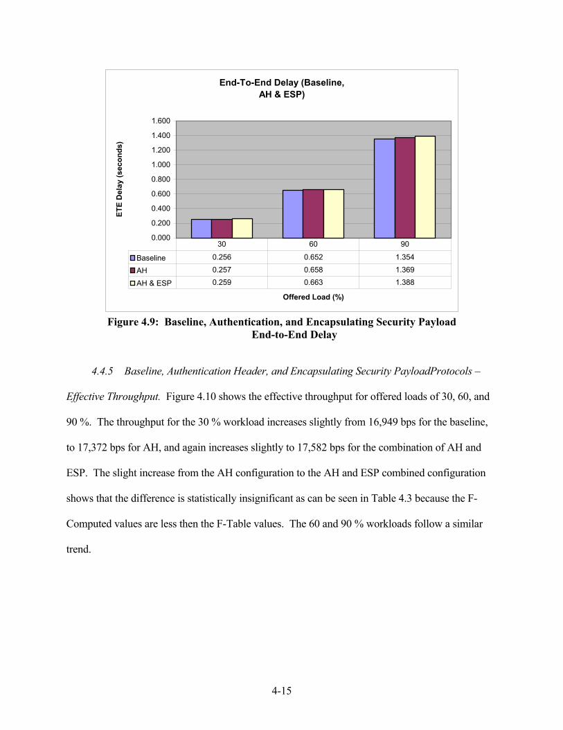
4-15
End-To-End Delay (Baseline, AH & ESP)
0.000
0.200
0.400
0.600
0.800
1.000
1.200
1.400
1.600
Offered Load (%)
ETE
Del
ay (s
econ
ds)
Baseline 0.256 0.652 1.354
AH 0.257 0.658 1.369
AH & ESP 0.259 0.663 1.388
30 60 90
Figure 4.9: Baseline, Authentication, and Encapsulating Security Payload
End-to-End Delay
4.4.5 Baseline, Authentication Header, and Encapsulating Security PayloadProtocols –
Effective Throughput. Figure 4.10 shows the effective throughput for offered loads of 30, 60, and
90 %. The throughput for the 30 % workload increases slightly from 16,949 bps for the baseline,
to 17,372 bps for AH, and again increases slightly to 17,582 bps for the combination of AH and
ESP. The slight increase from the AH configuration to the AH and ESP combined configuration
shows that the difference is statistically insignificant as can be seen in Table 4.3 because the F-
Computed values are less then the F-Table values. The 60 and 90 % workloads follow a similar
trend.

4-16
Effective Throughput (Baseline, AH, & ESP)
0
10000
20000
30000
40000
50000
60000
Offered Load (%)
Thro
ughp
ut (b
ps)
Baseline 16949 34491 51798
AH 17372 34906 51981
AH & ESP 17582 35362 52201
30 60 90
Figure 4.10: Baseline, Authentication, and Encapsulating Security Payload
Effective Throughput
4.5 Result Analysis
The next sections present an analysis comparing the three overhead variations (baseline, AH,
AH and ESP combined) to the offered load variations (30, 60, 90 % offered load). All the
ANOVA tables and derivation formulas are also displayed together in Appendices A through C.
4.5.1 End-To-End (ETE)Delay Analysis. As seen in Figure 4-9 above, the ETE delay
increases as packet size (offered load) increases. The variation shown in Table 4.3 shows that
99.94 % of the variation was due to the change in workload. Only 0.02 % of the variation was due
to increased overhead. The variation due to overhead-workload interaction was 0.01 % and
variation due to error was 0.02 %. Because the F-Computed value for offered load is significantly
larger than the F-Table value, this confirms that offered load has a significant impact in Link-16
network performance. The F-Computed value for the overhead variation is slightly larger than the
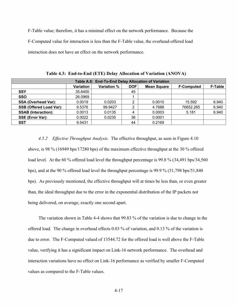
4-17
F-Table value; therefore, it has a minimal effect on the network performance. Because the
F-Computed value for interaction is less than the F-Table value, the overhead-offered load
interaction does not have an effect on the network performance.
Table 4.3: End-to-End (ETE) Delay Allocation of Variation (ANOVA)
4.5.2 Effective Throughput Analysis. The effective throughput, as seen in Figure 4.10
above, is 98 % (16949 bps/17280 bps) of the maximum effective throughput at the 30 % offered
load level. At the 60 % offered load level the throughput percentage is 99.8 % (34,491 bps/34,560
bps), and at the 90 % offered load level the throughput percentage is 99.9 % (51,798 bps/51,840
bps). As previously mentioned, the effective throughput will at times be less than, or even greater
than, the ideal throughput due to the error in the exponential distribution of the IP packets not
being delivered, on average, exactly one second apart.
The variation shown in Table 4-4 shows that 99.83 % of the variation is due to change in the
offered load. The change in overhead effects 0.03 % of variation, and 0.13 % of the variation is
due to error. The F-Computed valued of 13544.72 for the offered load is well above the F-Table
value, verifying it has a significant impact on Link-16 network performance. The overhead and
interaction variations have no effect on Link-16 performance as verified by smaller F-Computed
values as compared to the F-Table values.
Table A.6: End-To-End Delay Allocation of Variation Variation Variation % DOF Mean Square F-Computed F-TableSSY 35.6400 45 SSO 26.0969 1 SSA (Overhead Var): 0.0019 0.0203 2 0.0010 15.592 6.940 SSB (Offered Load Var): 9.5376 99.9427 2 4.7688 76652.265 6.940 SSAB (Interaction): 0.0013 0.0135 4 0.0003 5.181 6.940 SSE (Error Var): 0.0022 0.0235 36 0.0001 SST 9.5431 44 0.2169

4-18
Table 4.4: Effective Throughput Allocation of Variation (ANOVA)
Table B.6: Effective Throughput Allocation of Variation Variation Variation % DOF Mean Square F-Computed F-Table
SSY 63345625271 45 SSO 54302809601 1 SSA (Overhead Var): 3032934 0.03 2 1516467 4.55 6.94 SSB (Offered Load Var): 9027475902 99.83 2 4513737951 13544.72 6.94 SSAB (Interaction): 309939 0.00 4 77485 0.23 6.94 SSE (Error Var): 11996896 0.13 36 333247 SST 9042815670 44 205518538
4.5.3 Raw Throughput Analysis. Figure 4.11 shows the raw throughput for the all three
offered loads and all three overhead configurations. The raw throughput is actually greater than
the number of data bits offered at the host terminal because of the overhead bits added to the data
load before the JTIDS terminal transmits the JTIDS word.
Raw Throughput (Baseline, AH, & ESP)
0
10000
20000
30000
40000
50000
60000
Offered Load (%)
Thro
ughp
ut (b
ps)
Baseline 18449 37061 55945
AH 18623 37437 56281
AH & ESP 18860 37652 56488
30 60 90
Figure 4.11: Baseline, Authentication Header, and Encapsulating
Security Payload Raw Throughput

4-19
4.6 Confidence Interval(CI) Analysis
CI analysis can be used to determine if a measured value is significantly different from zero.
The analysis is performed by checking the CI interval to see if it includes the value zero. If the CI
includes zero, then the measured values are not significantly different than zero. Appendix A
(Tables A.7 and A.8) and Appendix B (Tables B.7 and B.8) show the CI for the ETE delay and
throughput offered load and overhead effects. The CI analysis shows that the results from the
varied offered loads are significant, but the results from the varied security levels are not
significant.
4.7 Summary
This chapter described the verification of the OPNET Link-16 model and the resultant data
from that model. Next, the implementation and results of the IP baseline model used for this
research were explained. Then a performance summary of the overhead and workload variations
was described. Finally an analysis of the results and data variations was explained.

5-1
V. Conclusions and Future Work
5.1 Overview
The JBI concept is within reach of becoming reality now that information technologies, in
particular Internet technologies, are reaching a quality-of-service level that provides sufficient
bandwidth for fast-paced war-fighting requirements. As various communication sub-systems are
pieced together to form a network-centric JBI, Information Assurance becomes a chief concern.
IPSec provides another security layer in the overall JBI security scheme. The research goal was
to determine the feasibility of passing IP messages and IPSec messages over a Link-16 network.
Sub-goals included performance analysis by comparing the effect that additional overhead from
the IPSec security protocols has on a Link-16 network. In addition, various workloads were
placed on the network to see how overall ETE delay and throughput are affected.
5.2 Conclusions
Since the IPSec security protocols add minimal overhead to the IP packet, and even though
the Link-16 network is relatively slow (57.6 kbps) compared to most Internet pipelines, it has
minimal effect on Link-16 ETE delay and throughput. Similar to varying the security levels,
varying the offered load has a minimal effect on effective throughput. At the 60 % offered load
level, effective throughput is 99.8 % of the maximum capacity. At the 90 % offered load level,
effective throughput is 99.9 % of maximum capacity. Here we see, that an offered load through
the 90 % level does not negatively impact the performance of the Link-16 network. However,
the Link-16 data rates are still not adequate to for transferring large data files that typically
traverse the Internet. Some research has been done, suggesting the Link-16 network can operate
up to 1.0 Mbps. An effective throughput near the 1.0 Mbps level would be adequate to process
large imagery files which typically range in size from 2 to 5 megabytes. At an average effective
5-2
throughput rate of 1.0 Mbps, a typical imagery file of 3 to 5 megabytes can take 3 to 5 seconds
to download.
5.3 Contributions
This research demonstrates that although the IPSec security protocols contribute minimal to
IP packet overhead, the main problem is that the Link-16 network is a legacy system that is far
too slow to transfer large size data files. The AH and ESP security protocols can be added to the
IPv6 packets with minimal effect on ETE delay and effective throughput. However, as offered
load increases beyond 6.5 kbps, throughput begins to degrade rapidly. Therefore, the Link-16
network can transmit IP packets provided the average bytes per second rate doesn’t exceed 6.5
kbps. The addition of IPSec protocols has minimal impact on the Link-16 network and does not
degrade its performance.
5.4 Future Work
Since the USAF Tactical Datalink Roadmap has determined that Link-16 will be around for
long term use, future work and research will always be useful to discover methods of improving
the Link-16 data rate, such as software modifications or compression techniques. Further
research can be conducted in this area by adjusting the Link-16 data rates to current maximum
capacity of 238 kbps to determine effective throughput at that rate. Hardware modifications can
also be made which effect the carrier modulation to increase the number of words in the packing
structure.
It should be noted that the OPNET Link-16 model used in this research was one of the
early versions of several planned iterations, and some features such as relay and net stacking, are

5-3
not part of the current model set. Possible future research may include the use of multiple nets
to simultaneously transmit data to increase throughput. It would be beneficial to validate the
OPNET Link-16 model used in this research work. However, real-time data is needed to
validate results obtains from the Link-16 model.

A-1
Appendix A. End-to-End Delay Allocation of Variation (ANOVA) Worksheet
Table A.1: End-To-End Delay Data Offered Load (%) Baseline AH AH & ESP
30 17280 bits 17504 bits 17712 bits 0.254309 0.257448 0.261042 0.252114 0.256790 0.258394 0.258622 0.253870 0.254543 0.248114 0.258590 0.263156 0.264652 0.257132 0.256534
60 34560 bits 34784 bits 34992 bits 0.648327 0.658174 0.662515 0.647106 0.667412 0.657479 0.663169 0.657781 0.672983 0.659590 0.653576 0.657880 0.640772 0.650811 0.663237
90 51840 bits 52064 bits 52272 bits 1.339830 1.352140 1.392471 1.366074 1.365532 1.383270 1.347827 1.377320 1.388572 1.371586 1.373314 1.390297 1.342722 1.378324 1.383547
Table A.2: End-To-End Delay Mean Offered Load (%) Baseline AH AH & ESP
30 0.256 0.257 0.259 60 0.652 0.658 0.663 90 1.354 1.369 1.388
Table A.3: End-To-End Delay Standard Deviations Offered Load (%) Baseline AH AH & ESP
30 0.006343 0.001754 0.003442 60 0.009296 0.006303 0.006255 90 0.014321 0.010846 0.004096

A-2
Table A.4: End-To-End Delay Computation of Effects Offered Load (%) Baseline AH AH & ESP Row Sum Row Mean Row Effect
30 0.255562 0.256766 0.258734 0.771062 0.25702068 -0.504511482 60 0.651793 0.657551 0.662819 1.972162 0.65738741 -0.104144756 90 1.353608 1.369326 1.387631 4.110565 1.3701884 0.608656238
Column Sum 2.260963 2.283643 2.309184 Column Mean 0.753654 0.761214 0.769728 0.761532 Column Effect -0.007878 -0.000318 0.008196
Table A.5: End-To-End Delay Interaction Effects Offered Load (%) Baseline AH AH & ESP
30 0.006419 0.000063 -0.006483 0.000000 60 0.002283 0.000481 -0.002764 0.000000 90 -0.008703 -0.000545 0.009247 0.000000
0.000000 0.000000 0.000000
Table A.6: End-To-End Delay Allocation of Variation Variation Variation % DOF Mean Square F-Computed F-Table
SSY 35.6400 45 SSO 26.0969 1 SSA (Overhead Var): 0.0019 0.0203 2 0.0010 15.592 6.940 SSB (Offered Load Var): 9.5376 99.9427 2 4.7688 76652.265 6.940 SSAB (Interaction): 0.0013 0.0135 4 0.0003 5.181 6.940 SSE (Error Var): 0.0022 0.0235 36 0.0001 SST 9.5431 44 0.2169
Table A.7: Confidence Interval For Overhead Effects Parameter Mean Effect Standard Dev. C.I. (low end) C.I. (high end)
0.7615 0.0012 0.7592 0.7638 Overhead Baseline -0.0079 0.0017 -0.0111 -0.0046
AH -0.0003 0.0017 -0.0036 0.0029 AH & ESP 0.0082 0.0017 0.0049 0.0115
Table A.8: Confidence Interval For Offered Load Effects
Parameter Mean Effect Standard Dev. C.I. (low end) C.I. (high end) 0.7615 0.0012 0.7596 0.7638
Offered Load 30% -0.5045 0.0017 -0.5078 -0.5013 60% -0.1041 0.0017 -0.1074 -0.1009 90% 0.6087 0.0017 0.6054 0.6119
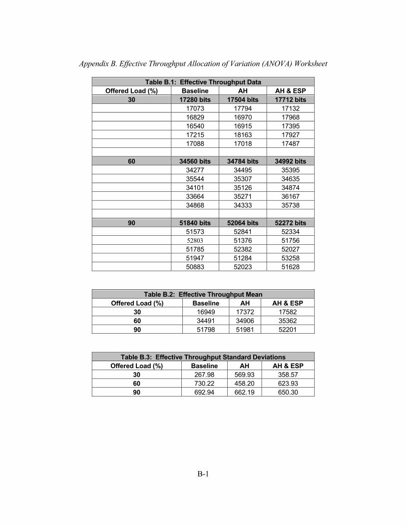
B-1
Appendix B. Effective Throughput Allocation of Variation (ANOVA) Worksheet
Table B.1: Effective Throughput Data Offered Load (%) Baseline AH AH & ESP
30 17280 bits 17504 bits 17712 bits 17073 17794 17132 16829 16970 17968 16540 16915 17395 17215 18163 17927 17088 17018 17487
60 34560 bits 34784 bits 34992 bits 34277 34495 35395 35544 35307 34635 34101 35126 34874 33664 35271 36167 34868 34333 35738
90 51840 bits 52064 bits 52272 bits 51573 52841 52334 52803 51376 51756 51785 52382 52027 51947 51284 53258 50883 52023 51628
Table B.2: Effective Throughput Mean Offered Load (%) Baseline AH AH & ESP
30 16949 17372 17582 60 34491 34906 35362 90 51798 51981 52201
Table B.3: Effective Throughput Standard Deviations Offered Load (%) Baseline AH AH & ESP
30 267.98 569.93 358.57 60 730.22 458.20 623.93 90 692.94 662.19 650.30
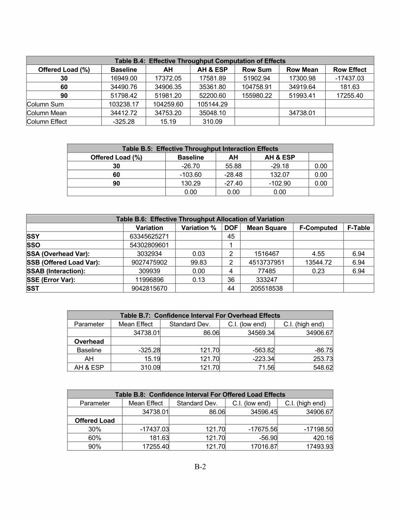
B-2
Table B.4: Effective Throughput Computation of Effects Offered Load (%) Baseline AH AH & ESP Row Sum Row Mean Row Effect
30 16949.00 17372.05 17581.89 51902.94 17300.98 -17437.03 60 34490.76 34906.35 35361.80 104758.91 34919.64 181.63 90 51798.42 51981.20 52200.60 155980.22 51993.41 17255.40
Column Sum 103238.17 104259.60 105144.29 Column Mean 34412.72 34753.20 35048.10 34738.01 Column Effect -325.28 15.19 310.09
Table B.5: Effective Throughput Interaction Effects Offered Load (%) Baseline AH AH & ESP
30 -26.70 55.88 -29.18 0.00 60 -103.60 -28.48 132.07 0.00 90 130.29 -27.40 -102.90 0.00
0.00 0.00 0.00
Table B.6: Effective Throughput Allocation of Variation Variation Variation % DOF Mean Square F-Computed F-Table
SSY 63345625271 45 SSO 54302809601 1 SSA (Overhead Var): 3032934 0.03 2 1516467 4.55 6.94 SSB (Offered Load Var): 9027475902 99.83 2 4513737951 13544.72 6.94 SSAB (Interaction): 309939 0.00 4 77485 0.23 6.94 SSE (Error Var): 11996896 0.13 36 333247 SST 9042815670 44 205518538
Table B.7: Confidence Interval For Overhead Effects Parameter Mean Effect Standard Dev. C.I. (low end) C.I. (high end)
34738.01 86.06 34569.34 34906.67Overhead Baseline -325.28 121.70 -563.82 -86.75
AH 15.19 121.70 -223.34 253.73AH & ESP 310.09 121.70 71.56 548.62
Table B.8: Confidence Interval For Offered Load Effects Parameter Mean Effect Standard Dev. C.I. (low end) C.I. (high end)
34738.01 86.06 34596.45 34906.67Offered Load
30% -17437.03 121.70 -17675.56 -17198.5060% 181.63 121.70 -56.90 420.1690% 17255.40 121.70 17016.87 17493.93

C-1
Appendix C. Raw Throughput Charts
Raw Throughput (Baseline)
30
60
90
0
10000
20000
30000
40000
50000
60000
Offered Load (%)
Thro
ughp
ut (b
ps)
Figure C.1: Raw Throughput (Baseline)
Raw Throughput (Baseline & AH)
0
10000
20000
30000
40000
50000
60000
Offered Load (%)
Thro
ughp
ut (b
ps)
BaselineAH
Baseline 18449 37061 55945
AH 18623 37437 56281
30 60 90
Figure C.2: Raw Throughput (Baseline and AH)

C-2
Raw Throughput (Baseline, AH, & ESP)
0
10000
20000
30000
40000
50000
60000
Offered Load (%)
Thro
ughp
ut (b
ps)
Baseline 18449 37061 55945
AH 18623 37437 56281
AH & ESP 18860 37652 56488
30 60 90
Figure C.3: Raw Throughput (Baseline, AH, and ESP)

D-1
Appendix D. Sample Size for Determining Mean
Table D.1: Baseline 30% Baseline 95% C.I., z = 1.96 Std. Dev: 0.006343 Sample Mean: 0.255562 1.243184Accuracy, r (%) = 5 1.277811n = 0.9465 0.972901 60% Baseline 95% C.I., z = 1.96 Std. Dev: 0.022164 Sample Mean: 0.469752 4.344159Accuracy, r (%) = 5 2.348761n = 3.4208 1.849553 90% Baseline 95% C.I., z = 1.96 Std. Dev: 0.039549 Sample Mean: 1.060222 7.751524Accuracy, r (%) = 5 5.30111 n = 2.1382 1.462245
Table D.2: Authentication Header (AH) 30% AH 95% C.I., z = 1.96 Std. Dev: 0.006455 Sample Mean: 0.273497 1.265097Accuracy, r (%) = 5 1.367486n = 0.8559 0.925126 60% AH 95% C.I., z = 1.96 Std. Dev: 0.009691 Sample Mean: 0.469752 1.899386Accuracy, r (%) = 5 2.348761n = 0.6540 0.808676 90% AH 95% C.I., z = 1.96 Std. Dev: 0.012579 Sample Mean: 1.060222 2.465449Accuracy, r (%) = 5 5.30111 n = 0.2163 0.465082

D-2
Table D.3: AH & ESP 30% AH & ESP 95% C.I., z = 1.96 Std. Dev: 0.013140 Sample Mean: 0.255562 2.575354Accuracy, r (%) = 5 1.277811n = 4.0620 2.015442 60% AH & ESP 95% C.I., z = 1.96 Std. Dev: 0.013571 Sample Mean: 0.514804 2.659843Accuracy, r (%) = 5 2.574022n = 1.0678 1.033341 90% AH & ESP 95% C.I., z = 1.96 Std. Dev: 0.007291 Sample Mean: 1.091631 1.429121Accuracy, r (%) = 5 5.458157n = 0.0686 0.261832
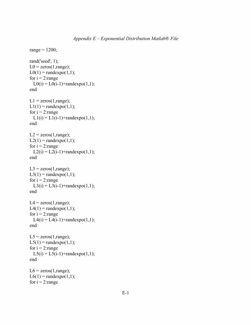
E-1
Appendix E – Exponential Distribution Matlab File range = 1200; rand('seed', 1); L0 = zeros(1,range); L0(1) = randexpo(1,1); for i = 2:range L0(i) = L0(i-1)+randexpo(1,1); end L1 = zeros(1,range); L1(1) = randexpo(1,1); for i = 2:range L1(i) = L1(i-1)+randexpo(1,1); end L2 = zeros(1,range); L2(1) = randexpo(1,1); for i = 2:range L2(i) = L2(i-1)+randexpo(1,1); end L3 = zeros(1,range); L3(1) = randexpo(1,1); for i = 2:range L3(i) = L3(i-1)+randexpo(1,1); end L4 = zeros(1,range); L4(1) = randexpo(1,1); for i = 2:range L4(i) = L4(i-1)+randexpo(1,1); end L5 = zeros(1,range); L5(1) = randexpo(1,1); for i = 2:range L5(i) = L5(i-1)+randexpo(1,1); end L6 = zeros(1,range); L6(1) = randexpo(1,1); for i = 2:range
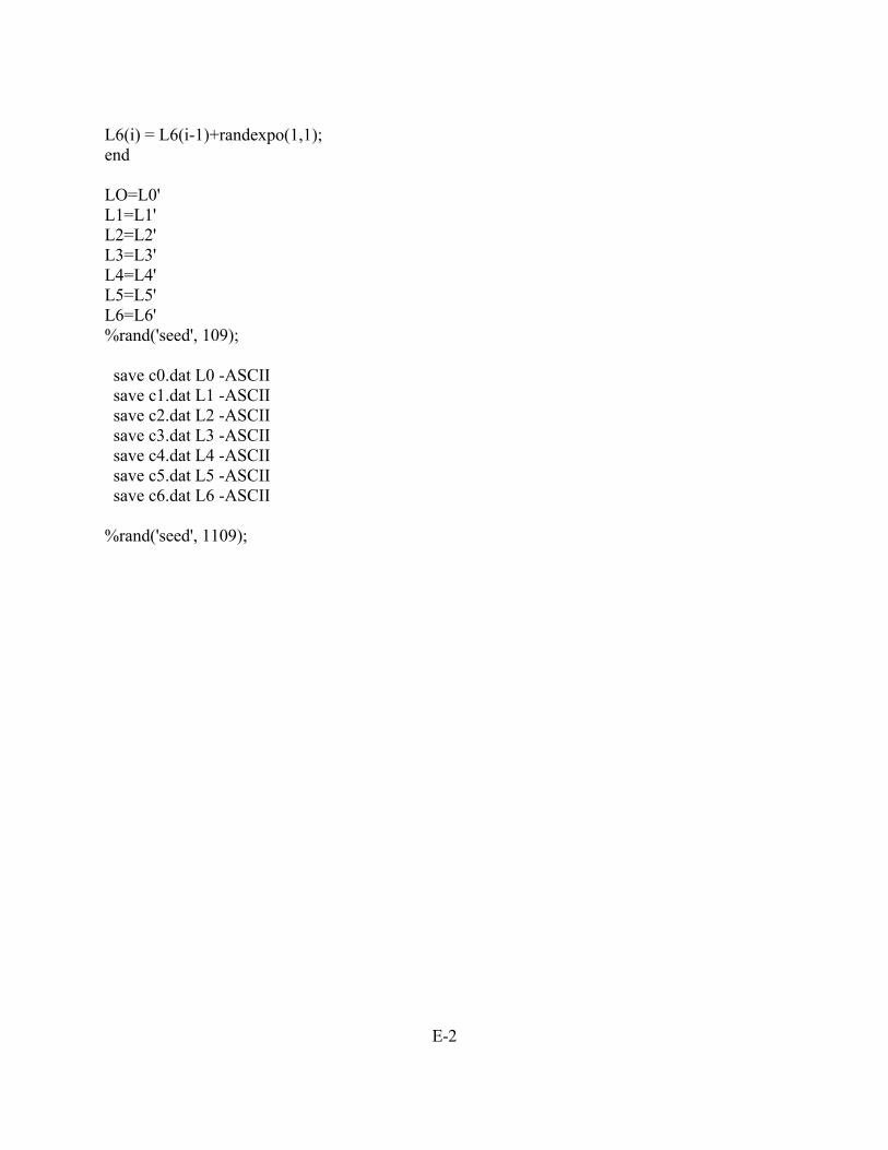
E-2
L6(i) = L6(i-1)+randexpo(1,1); end LO=L0' L1=L1' L2=L2' L3=L3' L4=L4' L5=L5' L6=L6' %rand('seed', 109); save c0.dat L0 -ASCII save c1.dat L1 -ASCII save c2.dat L2 -ASCII save c3.dat L3 -ASCII save c4.dat L4 -ASCII save c5.dat L5 -ASCII save c6.dat L6 -ASCII %rand('seed', 1109);

BIB-1
Bibliography
[Cha01] Chandler, D., MP-RTIP/WAS & Joint STARS MP-CDL Vision briefing, ESC/SRV
(MITRE)., 1 May 2001. [CDK01] Coulouris, George, Jean Dollimore and Tim Kindberg, Distributed Systems:
Concepts and Design, Addison-Wesley, 2001. [DGSP97] Davis, Barry B., Cecil Graham, David Stamm and Chriss Parker, Tactical Digital
Information Link (TADIL) J Range Extension (JRE), June 1997. [Jai91] Jain, Raj, The Art of Computer Systems Performance of Analysis: Techniques for
Experimental Design, Measurement, Simulation, and Modeling, John Wiley & Sons, Inc. 1991.
[JaW00] Joe-Ng, M. and D. Wong, IP Mobility Management for the Airborne
Communications Node Platform, Telcordia Tech. Inc. 2000. [Kae99] Kaeo, Merike, Designing Network Security, Cisco Press, 1999. [Kim98] Kim, Jae H., ATM Network-Based Integrated Battlespace Simulation With Multiple
UAV-AWACS-Fighter Platforms, USAF Research Lab, Rome NY. 1998. [Loc03] Lockheed Martin, F/A-22 Raptor Official Website, www.f-22raptor.com, February 2003 [Nor01] Northrop Gruman, Understanding Link-16. A Guidebook for New Users,
September 2001. [PIX02] Preaward Information exchange System (PIXS),
www.pixs.wpafb.af.mil/pixslibr/mp-cdl/mp-cdl.asp, 25 Jan 2002. [Ray01] The Raytheon Company, Embedded Information System Assurance (EISA) Phase
1: Domain Analysis, 13 April 2001. [RFC 2002] Perkins, C., IP Mobility Report, www.ieft.org, October 1996. [RFC 2401] Kent, S. and R. Atkinson, Security Architecture for the Internet Protocol.
www.ietf.org, November 1998. [RFC 2411] Thayer, R., IP Security Document Roadmap, www.ietf.org, November 1998.

BIB-2
[RFC 2460] Deering, S. and R. Hinden, Internet Protocol, Version 6 (IPv6) Specification, December 1998.
[SAB99] U.S. Air Force Scientific Advisory Board, Report on Building the Joint Battlespace
Infosphere Volume 1, SAB-TR-99-02, 1999. [SaB94] Sorgi, Al and Kesh Bakhru, Surveillance and Control Data Link Network
(SCDLN) for Joint STARTS, May 1994. [TaV02] Tanenbaum, A., and Maarten Van Steen, Distributed Systems, Principles and
Paradigms. Prentice-Hall, Inc; 2002. [USAF01] Combat Air Forces, Mobility Air Forces, and Air Force Material Command
Ratification, United States Air Force Tactical Datalink Roadmap, 27 August 2001.

VITA-1
Vita Clint Stinson is a Captain in the U.S. Air Force. He is a M.S. candidate in the Department of
Electrical and Computer Engineering, Graduate School of Engineering and Management, Air
Force Institute of Technology. He received his B.S. in Computer Engineering from the University
of Utah in 1997. His technical interests include computer networking and information systems
security.
REPORT DOCUMENTATION PAGE Form Approved OMB No. 074-0188
The public reporting burden for this collection of information is estimated to average 1 hour per response, including the time for reviewing instructions, searching existing data sources, gathering and maintaining the data needed, and completing and reviewing the collection of information. Send comments regarding this burden estimate or any other aspect of the collection of information, including suggestions for reducing this burden to Department of Defense, Washington Headquarters Services, Directorate for Information Operations and Reports (0704-0188), 1215 Jefferson Davis Highway, Suite 1204, Arlington, VA 22202-4302. Respondents should be aware that notwithstanding any other provision of law, no person shall be subject to an penalty for failing to comply with a collection of information if it does not display a currently valid OMB control number. PLEASE DO NOT RETURN YOUR FORM TO THE ABOVE ADDRESS. 1. REPORT DATE (DD-MM-YYYY)
25-03-2003 2. REPORT TYPE
Master’s Thesis
3. DATES COVERED (From – To) Aug 2001 – Mar 2003
5a. CONTRACT NUMBER
5b. GRANT NUMBER
4. TITLE AND SUBTITLE INTERNET PROTOCOL (IP) OVER LINK-16
5c. PROGRAM ELEMENT NUMBER
5d. PROJECT NUMBER If funded, enter ENR # 5e. TASK NUMBER
6. AUTHOR(S) Stinson, Clinton, W., Captain, USAF 5f. WORK UNIT NUMBER
7. PERFORMING ORGANIZATION NAMES(S) AND ADDRESS(S) Air Force Institute of Technology Graduate School of Engineering and Management (AFIT/EN) 2950 Hobson Way, Building 640 WPAFB OH 45433-7765
8. PERFORMING ORGANIZATION REPORT NUMBER AFIT/GCE/ENG/03-04
10. SPONSOR/MONITOR’S ACRONYM(S)
9. SPONSORING/MONITORING AGENCY NAME(S) AND ADDRESS(ES) AFRL/IFTA (AFMC) Attn: Mr. Tod Reinhart 2241 Avionics Circle B620 DSN: 785-6548 x3582 WPAFB OH 45433-7334 email: [email protected]
11. SPONSOR/MONITOR’S REPORT NUMBER(S)
12. DISTRIBUTION/AVAILABILITY STATEMENT APPROVED FOR PUBLIC RELEASE; DISTRIBUTION UNLIMITED.
13. SUPPLEMENTARY NOTES 14. ABSTRACT The purpose of Link-16 is to exchange real-time tactical data among units of the United States and allied forces. Primary Link-16 functions include exchange of friendly unit position and status data, the dissemination of tactical surveillance track data, and the control/management of air, surface, and subsurface engagements. Because Link-16 will play an integral role in the network-centric Joint Battlespace Infosphere (JBI), the performance of Internet Protocol version six (IPv6) and IP Security (IPSec) over Link-16 needs to be determined. Using OPNET modeling software to simulate a Link-16 network, the investigation of this research revealed that the overhead from IPv6 and IPSec does not significantly affect end-to-end delay and effective throughput of the Link-16 network. As long as the encryption and authentication protocols are preprocessed, these protocols add minimal amounts of latency overhead to the Link-16 network. However, as the offered load is extended beyond the 90% level, the overhead from the IPSec extensions begins to have more of a negative effect on the End-to-End delay and throughput. Therefore, as the offered load increases beyond the 90% level, it begins to have a significant impact on the performance of the Link-16 network. 15. SUBJECT TERMS Link-16, TADIL-J, Common Data Link, Network Security, Information Assurance, Internet Protocol
16. SECURITY CLASSIFICATION OF: 19a. NAME OF RESPONSIBLE PERSON Rusty O. Baldwin, Major, USAF (ENG)
a. REPORT
U
b. ABSTRACT
U
c. THIS PAGE
U
17. LIMITATION OF ABSTRACT
UU
18. NUMBER OF PAGES
86 19b. TELEPHONE NUMBER (Include area code) (937) 255-3636, ext 4612; e-mail: [email protected]
Standard Form 298 (Rev. 8-98) Prescribed by ANSI Std. Z39-18