air conditioning – air conditioning system ac–3remont-oshibki.ru/files/manuals/8553/air...
TRANSCRIPT
AIR CONDITIONING – AIR CONDITIONING SYSTEM AC–3
C
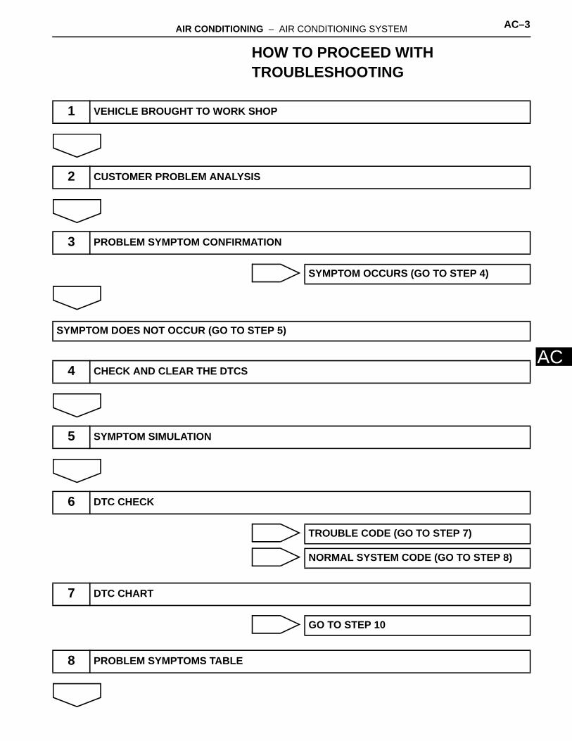
AHOW TO PROCEED WITH TROUBLESHOOTING
1 VEHICLE BROUGHT TO WORK SHOP
2 CUSTOMER PROBLEM ANALYSIS
3 PROBLEM SYMPTOM CONFIRMATION
SYMPTOM OCCURS (GO TO STEP 4)
SYMPTOM DOES NOT OCCUR (GO TO STEP 5)
4 CHECK AND CLEAR THE DTCS
5 SYMPTOM SIMULATION
6 DTC CHECK
TROUBLE CODE (GO TO STEP 7)
NORMAL SYSTEM CODE (GO TO STEP 8)
7 DTC CHART
GO TO STEP 10
8 PROBLEM SYMPTOMS TABLE

AC–4 AIR CONDITIONING – AIR CONDITIONING SYSTEM
AC
9 ACTUATOR CHECK
10 CIRCUIT INSPECTION
11 IDENTIFYING OF PROBLEMS
12 PARTS INSPECTION
13 REPAIR
14 CONFIRMATION TEST
15 END

AIR CONDITIONING – AIR CONDITIONING SYSTEM AC–5
C
APARTS LOCATION
COOLER CONDENSER TEMPERATURE SENSOR (COOLER (AMBIENT TEMPERATURE SENSOR) THERMISTOR)
ENGINE ROOM J/B AND R/B
HTR FUSE
D.C.C FUSE
COMPRESSOR AND MAGNETIC CLUTCH
CONDENSER
PRESSURE SWITCH
HEATER BLOWER MOTOR RELAY
MAGNETIC CLUTCH RELAY
E112561E03

AC–6 AIR CONDITIONING – AIR CONDITIONING SYSTEM
AC
A/C SOLAR SENSOR (COOLER (SOLAR SENSOR) THERMISTOR
CLOCK ASSEMBLY
ECM
AIR CONDITIONER AMPLIFIER
DRIVE SIDE J/B
ECU-B FUSE
HTR FUSE
IG1 RELAYA/C ROOM TEMPERATURE SENSOR (COOLER (ROOM TEMPERATURE SENSOR) THERMISTOR)
AIR CONDITIONING CONTROL ASSEMBLY
E112562E01
AIR CONDITIONING – AIR CONDITIONING SYSTEM AC–7
C
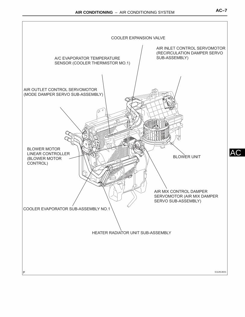
AAIR OUTLET CONTROL SERVOMOTOR (MODE DAMPER SERVO SUB-ASSEMBLY)
A/C EVAPORATOR TEMPERATURE SENSOR (COOLER THERMISTOR MO.1)
COOLER EXPANSION VALVE
AIR INLET CONTROL SERVOMOTOR (RECIRCULATION DAMPER SERVO SUB-ASSEMBLY)
AIR MIX CONTROL DAMPER SERVOMOTOR (AIR MIX DAMPER SERVO SUB-ASSEMBLY)
HEATER RADIATOR UNIT SUB-ASSEMBLY
COOLER EVAPORATOR SUB-ASSEMBLY NO.1
BLOWER MOTOR LINEAR CONTROLLER (BLOWER MOTOR CONTROL)
BLOWER UNIT
E112613E01

AC–8 AIR CONDITIONING – AIR CONDITIONING SYSTEM
AC
SYSTEM DIAGRAM
DEF
ECU-B
ST2
IG2
ST1
IG1
ACCBLR
AM1
AM2
CUT
ACC
Rr DEF Relay+B IG
HR
BL
TR
RDFG
ILL+
ILL-
SW1
SG-5
TE
SGS5
TS
GUGE2
Ignition Switch
IG Mian
HTR IG
MIR HTR
Rear Window Defogger
With Mirror Heater
HEATER Relay
Blower Motor Linear Controller
Room Temperature Sensor
Evaporator Temperature Sensor
Solar Sensor
Combination Meter (Rheostat)
Flasher Relay
Body ECU
TAIL
ALTER
A/C ECU
3MZ-FE:
E112563E01

AIR CONDITIONING – AIR CONDITIONING SYSTEM AC–9
C
AA/C ECU
LP
A/CS
ACI
TW
SPD
TAM
PSWSG-2
AC1
TPI
S5-2
SG-1
AIF
AIR
AOD
AOF
TPO
S5-1
SG-3
TP
S5-3
AMH
AMC
Air Inlet Control Servomotor
Air Outlet Control Servomotor
Air Mix Control Damper Servomotor
Water Temperature Sensor
Compressor Lock Sensor
Transponder ECU
ECM
A/C
ACINDTHW
E2
LCKI
PSW
E1
THEO
THWO
Magnet Clutch Relay
Magnetic Clutch Assembly
Ambient Temperature Sensor
Clock Assembly
A/C Pressure Switch
Combination Meter
3MZ-FE:
E112564E01

AC–10 AIR CONDITIONING – AIR CONDITIONING SYSTEM
AC
DEF
ECU-B
ST2
IG2
ST1
IG1
ACCBLR
AM1
AM2
CUT
ACC
Rr DEF Relay+B IG
HR
BLW
TR
RDFG
ILL+
ILL-
SW1
SG-5
TE
SGS5
TS
GUGE2
Ignition Switch
IG Mian
HTR IG
MIR HTR
Rear Window Defogger
With Mirror Heater
HEATER Relay
Blower Motor Linear Controller
Room Temperature Sensor
Evaporator Temperature Sensor
Solar Sensor
Combination Meter (Rheostat)
Flasher Relay
Body ECU
TAIL
ALTER
A/C ECU
2AZ-FE:
E112563E05
AIR CONDITIONING – AIR CONDITIONING SYSTEM AC–11
C
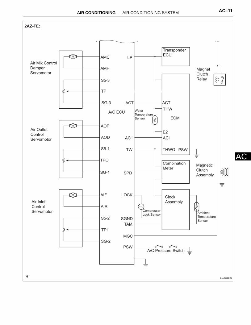
ALP
ACT
AC1
TW
SPD
LOCK
SGNDTAM
MGC
PSW
ACT
AMC
AMH
S5-3
TP
SG-3
AOF
AOD
S5-1
TPO
SG-1
AIF
AIR
S5-2
TPI
SG-2
A/C ECU
AC1
ECM
THW
E2
PSWTHWO
Transponder ECU
Combination Meter
Clock Assembly
Ambient Temperature Sensor
Compresser Lock Sensor
Water Temperature Sensor
Magnet Clutch Relay
Magnetic Clutch Assembly
A/C Pressure Switch
Air Mix Control Damper Servomotor
Air Outlet Control Servomotor
Air Inlet Control Servomotor
2AZ-FE:
E112566E01
AIR CONDITIONING – AIR CONDITIONING SYSTEM AC–43
C
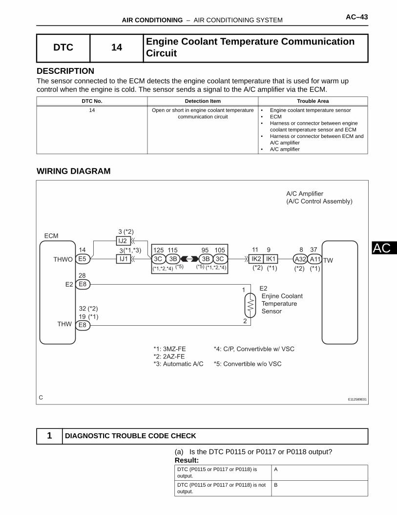
ADESCRIPTIONThe sensor connected to the ECM detects the engine coolant temperature that is used for warm up control when the engine is cold. The sensor sends a signal to the A/C amplifier via the ECM.
WIRING DIAGRAM
(a) Is the DTC P0115 or P0117 or P0118 output?Result:
DTC 14 Engine Coolant Temperature Communication Circuit
DTC No. Detection Item Trouble Area
14 Open or short in engine coolant temperature communication circuit
• Engine coolant temperature sensor• ECM• Harness or connector between engine
coolant temperature sensor and ECM• Harness or connector between ECM and
A/C amplifier• A/C amplifier
1 DIAGNOSTIC TROUBLE CODE CHECK
C
(*2) (*1)
A/C Amplifier (A/C Control Assembly)
A11A32
ECM
E2Enjine Coolant Temperature Sensor
E8
E8
E5
IJ2
IJ1THWO
E2
THW
3
3
(*2)
(*1,*3)3B 3C3C 3B
125 95 105115
(*1,*2,*4) (*5)
*1: 3MZ-FE *2: 2AZ-FE
(*2) (*1)(*1,*2,*4)(*5)IK1IK2
11 914
1
2
8 37
28
19
*3: Automatic A/C
*4: C/P, Convertivble w/ VSC
*5: Convertible w/o VSC
TW
32 (*2)(*1)
E112589E01
DTC (P0115 or P0117 or P0118) is output.
A
DTC (P0115 or P0117 or P0118) is not output.
B

AC–44 AIR CONDITIONING – AIR CONDITIONING SYSTEM
AC
B
A
(a) Measure the resistance according to the value(s) in the table below.
Standard resistance
*1: 3MZ-FE*2: 2AZ-FE
Go to step 2
GO TO ENGINE CONTROL SYSTEM
2 CHECK HARNESS AND CONNECTOR (A/C AMPLIFIER - ECM)
C
ECM Connector Wire Herness View:
2AZ-FE:3MZ-FE:
2AZ-FE:3MZ-FE:
Air Conditioning Amplifier Connector Wire Herness View:
A11 A32
E5 E5
THWO
TWTW
THWO
E112549E01
Tester connection Condition Specified condition
E5-14 (THWO) - A11-37 (TW)*1, A32-8 (TW)*2
Always Below 1 Ω
AIR CONDITIONING – AIR CONDITIONING SYSTEM AC–45
C
ANG
OK
REPAIR OR REPLACE HARNESS OR CONNECTOR
REPLACE AIR CONDITIONING AMPLIFIER

AIR CONDITIONING – AIR CONDITIONING SYSTEM AC–1
C
AAIR CONDITIONING SYSTEMPRECAUTION1. DO NOT HANDLE REFRIGERANT IN AN ENCLOSED
AREA OR NEAR AN OPEN FLAME2. ALWAYS WEAR EYE PROTECTION
3. BE CAREFUL NOT TO GET LIQUID REFRIGERANT IN YOUR EYES OR ON YOUR SKINIf liquid refrigerant gets in your eyes or on your skin:(a) wash the area with lots of cold water.
CAUTION:Do not rub your eyes or skin.
(b) apply clean petroleum jelly to the skin.(c) go immediately to a hospital or see a physician for
professional treatment.4. NEVER HEAT CONTAINER OR EXPOSE IT TO
NAKED FLAME5. BE CAREFUL NOT TO DROP CONTAINER AND NOT
TO APPLY PHYSICAL SHOCKS TO IT6. DO NOT OPERATE COMPRESSOR WITHOUT
ENOUGH REFRIGERANT IN REFRIGERANT SYSTEMIf there is not enough refrigerant in the refrigerant system, oil lubrication will be insufficient and compressor burnout may occur. Necessary care should be taken to avoid this.
7. DO NOT OPEN HIGH PRESSURE MANIFOLD VALVE WHILE COMPRESSOR IS OPERATINGOpen and close only the low pressure valve. If the high pressure valves are opened, refrigerant flows in the reverse direction causing the charging cylinder to rupture.
8. BE CAREFUL NOT TO OVERCHARGE SYSTEM WITH REFRIGERANTIf refrigerant is overcharged, it causes problems such as insufficient cooling, poor fuel economy, engine overheating, etc.
9. DO NOT OPERATE ENGINE AND COMPRESSOR WITH NO REFRIGERANT FILLEDCAUTION:This may damage the inside of the compressor because the compressor parts always move regardless of whether the A/C system is turned on or off.
AC02810
AC02811
Wrong Okay
N011084E06

AC–2 AIR CONDITIONING – AIR CONDITIONING SYSTEM
AC
10. PRECAUTION FOR DISCONNECTING THE BATTERY CABLENOTICE:When disconnecting the negative (-) battery terminal, initialize the following systems after the terminal is reconnected.
System Name See Procedure
Power Window Control System WS-6
Sliding Roof System RF-4

AC–46 AIR CONDITIONING – AIR CONDITIONING SYSTEM
AC
DESCRIPTIONA photo diode in the A/C solar sensor (cooler (solar sensor) thermistor) detects solar radiation and sends signals to the A/C amplifier.
WIRING DIAGRAM
(a) Remove the A/C amplifier with connectors still connected.
DTC 21 Solar Sensor Circuit
DTC No. Detection Item Trouble Area
21 Open or short in solar sensor circuit(If the check is performed in a dark place,
DTC 21 may be displayed.)
• A/C solar sensor (cooler (solar sensor) thermistor)
• Harness or connector between A/C solar sensor (cooler (solar sensor) thermistor) and A/C amplifier
• A/C amplifier
1 INSPECT AIR CONDITIONING AMPLIFIER (TS - S5)
Resistance of photodiode
High
LowWeak Strong
Strength of solar radiationE109314E02
C
A/C Amplifier (A/C Control Assembly)
*1: 3MZ-FE *2: 2AZ-FE
2 1A11A31
A11A31
(*1)(*2)
(*1)(*2)
24 28
23 25
S5
TS
A13A/C Solar Sensor (Cooler (Solar Sensor) Thermistor)
E112591E01

AIR CONDITIONING – AIR CONDITIONING SYSTEM AC–47
C
A(b) Measure the voltage according to the value(s) in the table below.Standard voltage:
Move the light away from the sensor under the following conditions:
Voltage increasesMove the light closer to the sensor under the following conditions:
Voltage decreases
*1: 3MZ-FE*2: 2AZ-FEHINT:• Use an incandescent lamp for inspection. Bring it
within 30 cm (11.8 in.) of the A/C solar sensor (cooler (solar sensor) thermistor)
Result:
B
C
A
(a) Remove the A/C solar sensor (cooler (solar sensor) thermistor).
(b) Measure the resistance according to the value(s) in the table below.
C
Air Conditioning Amplifier Connector Wire Harness View:
3MZ-FE: A11
A312AZ-FE:
TS (-)S5(+)
S5(+)TS (-)
E112546E05
Tester connection Condition Specified condition
A11-28 (S5)*1, A31-24Å@(S5)*2 - A11-25 (TS)*1, A31-23Å@(TS)*2
Ignition switch ON 0.8 to 4.3 V
NG A
OK(Checking from the PROBLEM SYMPTOMS TABLE)
B
OK (Checking from the DTC) C
PROCEED TO NEXT CIRCUIT INSPECTION SHOWN IN PROBLEM SYMPTOMS TABLE
REPLACE AIR CONDITIONING AMPLIFIER
2 INSPECT A/C SOLAR SENSOR (COOLER (SOLAR SENSOR) THERMISTOR)

AC–48 AIR CONDITIONING – AIR CONDITIONING SYSTEM
AC
(c) Connect the positive (+) lead from the ohmmeter to terminal 1 and negative (-) lead to terminal 2 of the A/C solar sensor.Standard resistance
NOTICE:The connection procedure for using a digital tester such as an TOYOTA electrical tester is shown above. When using an analog tester, connect the positive (+) lead to terminal 2 and negative (-) lead to terminal 1 of the A/C solar sensor.HINT:• As the inspection light is moved away from the
sensor, the voltage increases.• Use an incandescent lamp for inspection. Bring it
within 30 cm (11.8 in.) of the A/C solar sensor (cooler (solar sensor) thermistor).
NG
OK
(a) Measure the resistance according to the value(s) in the table below.
C
A/C Solar Sencer (Cooler (Solar Sensor) Thermistor) Connector Front View:
A13
2 (SS-) 1 (SS+)
E112578E01
Tester connection Condition Specified condition
A13-1 (SS+) - A13-2 (SS-)
Sensor is subject to electric light
Except ∞ Ω
A13-1 (SS+) - A13-2 (SS-)
Sensor is covered with a cloth
∞ Ω (No continuity)
REPLACE A/C SOLAR SENSOR
3 CHECK HARNESS AND CONNECTOR (A/C SOLAR SENSOR - AIR CONDITIONING AMPLIFIER)

AIR CONDITIONING – AIR CONDITIONING SYSTEM AC–49
C
AStandard resistance*1: 3MZ-FE*2: 2AZ-FE
NG
OK
C
A/C Solar Sensor (Cooler (Solar Sensor) Thermistor) Connector Front View:
A13
A31A11
Air Conditioning Amplifier Connector Wire Harness View:
3MZ-FE: 2AZ-FE:
S5 TS S5TS
E112547E03
Tester connection Condition Specified condition
A11-28 (S5)*1, A31-24 (S5)*2- A13-1
Always Below 1Ω
A11-25 (TS)*1, A31-24 (TS)*2 - A13-2
Always Below 1Ω
A11-28 (S5)*1, A31-24 (S5)*2 - Body ground
Always 10 kΩ or higher
A11-25 (TS)*1, A31-23 (TS)*2 - Body ground
Always 10 kΩ or higher
REPAIR OR REPLACE HARNESS OR CONNECTOR
REPLACE AIR CONDITIONING AMPLIFIER

AC–50 AIR CONDITIONING – AIR CONDITIONING SYSTEM
AC
DESCRIPTIONThis sensor sends 1 pulse per engine revolution to the ECM.If the ratio between engine and compressor speed deviates 20 % or more in compression to normal operation, the ECM turns the cooler compressor off and the indicator blinks at approximately 1 second intervals.The ECM ACLD terminal informs the A/C amplifier A/CI terminal of the cooler compressor's operating condition.
WIRING DIAGRAM
(a) Check and adjust compressor drive belt tension (see page).
DTC 22 Compressor Lock Sensor Circuit
DTC No. Detection Item Trouble Area
22 All conditions below are detected for 3 sec. or more
1.Engine speed: 450 rpm or more2.Ratio between engine and compressor
speed deviates 20 % or more in comparison to normal operation
• A/C lock sensor (cooler compressor assembly)
• Compressor drive belt• Harness and connector between ECM
and cooler compressor assembly, cooler compressor assembly and body ground.
• ECM• A/C amplifier
1 CHECK COOLER COMPRESSOR ASSEMBLY
A11
A32
A32
38
4
5
A/CI
LOCK
SGND
A/C Amplifier (A/C Control Assembley)
(*2)
(*2)
IK1
IM2
IM2
8
7
9
EE
(*1)E5
E6
A3A/C Lock Sensor (Cooler Compressor) J/C
ECM
ACLD
LCKI
(*1)
(*1)
AA
*1: 3MZ-FE *2: 2AZ-FE
33
23
I036556E01

AIR CONDITIONING – AIR CONDITIONING SYSTEM AC–51
C
A(b) Check if the cooler compressor does not lock when starting the engine and turning the A/C switch on.OK:
Cooler compressor assembly does not lock during operations
If the compressor drive belt slips when A/C switch is turned on, the magnetic clutch seems to be locked.If the condition continues for more than 3 seconds, the A/C amplifier turns off the magnetic clutch for compressor drive belt protection.
NG
OK
(a) Remove the ECM with the connectors still connected.(b) Start the engine and push the AUTO switch.(c) Measure the waveform according to the condition(s) in
the table below.
REPLACE COOLER COMPRESSOR ASSEMBLY
2 INSPECT LOCK SIGNAL
C
Air Conditioning Amplifier Connecter Wire Harness View:
A32
ECM Connector Wire Harness View:
E6
LOCK
lCKI
200mV / Division
GND
10 msec. / Division
SGND
3MZ-FE: 2AZ-FE:
E112559E01
AC–52 AIR CONDITIONING – AIR CONDITIONING SYSTEM
AC
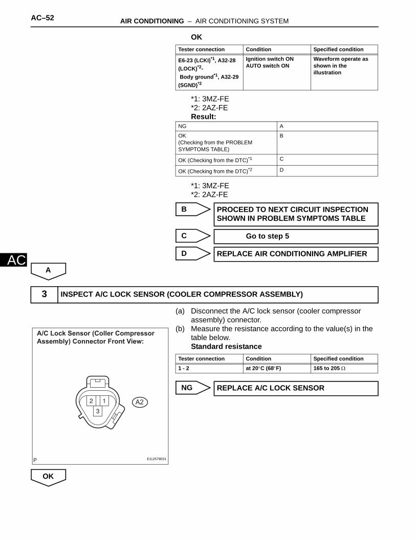
OK
*1: 3MZ-FE*2: 2AZ-FEResult:
*1: 3MZ-FE*2: 2AZ-FE
B
C
D
A
(a) Disconnect the A/C lock sensor (cooler compressor assembly) connector.
(b) Measure the resistance according to the value(s) in the table below.Standard resistance
NG
OK
Tester connection Condition Specified condition
E6-23 (LCKI)*1, A32-28 (LOCK)*2- Body ground*1, A32-29 (SGND)*2
Ignition switch ONAUTO switch ON
Waveform operate as shown in the illustration
NG A
OK(Checking from the PROBLEM SYMPTOMS TABLE)
B
OK (Checking from the DTC)*1 C
OK (Checking from the DTC)*2 D
PROCEED TO NEXT CIRCUIT INSPECTION SHOWN IN PROBLEM SYMPTOMS TABLE
Go to step 5
REPLACE AIR CONDITIONING AMPLIFIER
3 INSPECT A/C LOCK SENSOR (COOLER COMPRESSOR ASSEMBLY)
A/C Lock Sensor (Coller Compressor Assembly) Connector Front View:
A2
E112579E01
Tester connection Condition Specified condition
1 - 2 at 20°C (68°F) 165 to 205 Ω
REPLACE A/C LOCK SENSOR
AIR CONDITIONING – AIR CONDITIONING SYSTEM AC–53
C
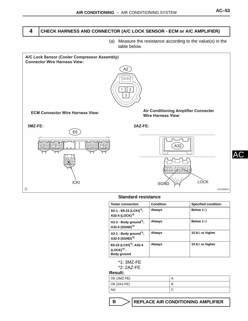
A(a) Measure the resistance according to the value(s) in the table below.
Standard resistance
*1: 3MZ-FE*2: 2AZ-FE
Result:
B
4 CHECK HARNESS AND CONNECTOR (A/C LOCK SENSOR - ECM or A/C AMPLIFIER)
C
Air Conditioning Amplifier Connecter Wire Harness View:
A32
ECM Connector Wire Harness View:
E6
LOCKlCKI SGND
A/C Lock Sensor (Cooler Compressor Assembly) Connector Wire Harness View:
A2
3MZ-FE: 2AZ-FE:
E112560E01
Tester connection Condition Specified condition
A2-1 - E6-23 (LCKI)*1, A32-4 (LOCK)*2
Always Below 1 Ω
A2-2 - Body ground*1, A32-5 (SGND)*2
Always Below 1 Ω
A2-1 - Body ground*1, A32-5 (SGND)*2
Always 10 kΩ or higher
E6-23 (LCKI)*1, A32-4 (LOCK)*2 - Body ground
Always 10 kΩ or higher
OK (3MZ-FE) A
OK (2AZ-FE) B
NG C
REPLACE AIR CONDITIONING AMPLIFIER
AC–54 AIR CONDITIONING – AIR CONDITIONING SYSTEM
AC
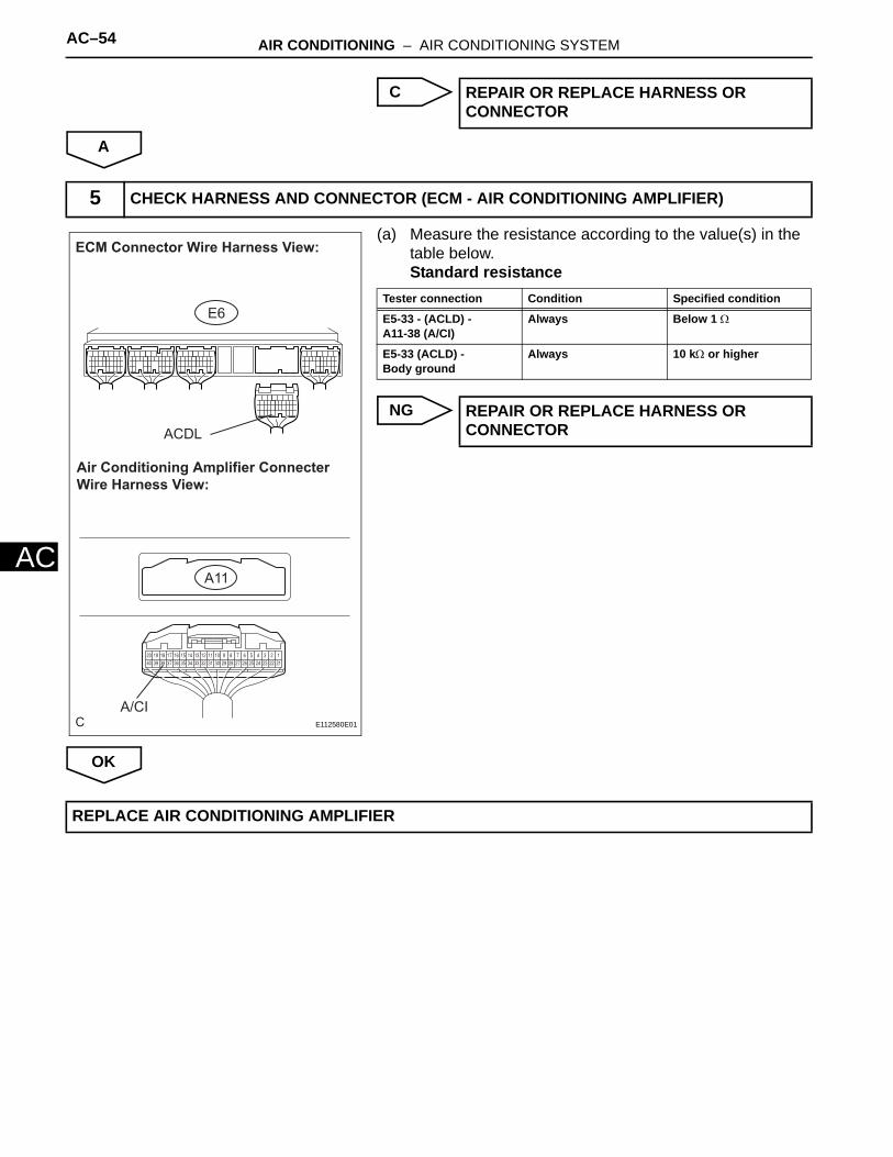
C
A
(a) Measure the resistance according to the value(s) in the table below.Standard resistance
NG
OK
REPAIR OR REPLACE HARNESS OR CONNECTOR
5 CHECK HARNESS AND CONNECTOR (ECM - AIR CONDITIONING AMPLIFIER)
C
ECM Connector Wire Harness View:
E6
ACDL
Air Conditioning Amplifier Connecter Wire Harness View:
A11
A/CIE112580E01
Tester connection Condition Specified condition
E5-33 - (ACLD) - A11-38 (A/CI)
Always Below 1 Ω
E5-33 (ACLD) - Body ground
Always 10 kΩ or higher
REPAIR OR REPLACE HARNESS OR CONNECTOR
REPLACE AIR CONDITIONING AMPLIFIER
AIR CONDITIONING – AIR CONDITIONING SYSTEM AC–55
C
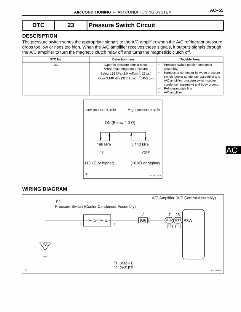
ADESCRIPTIONThe pressure switch sends the appropriate signals to the A/C amplifier when the A/C refrigerant pressure drops too low or rises too high. When the A/C amplifier receives these signals, it outputs signals through the A/C amplifier to turn the magnetic clutch relay off and turns the magneticic clutch off.
WIRING DIAGRAM
DTC 23 Pressure Switch Circuit
DTC No. Detection Item Trouble Area
23 •Open in pressure sensor circuit•Abnormal refrigerant pressure:
Below 196 kPa (2.0 kgf/cm 2, 28 psi) Over 3,140 kPa (32.0 kgf/cm 2, 455 psi)
• Pressure switch (cooler condenser assembly)
• Harness or connector between pressure switch (cooler condenser assembly) and A/C amplifier, pressure switch (cooler condenser assembly) and body ground
• Refrigerant pipe line• A/C amplifier
Low pressure side High pressure side
ON (Below 1.0 Ω)
196 kPa 3.140 kPa
OFF OFF
(10 kΩ or higher) (10 kΩ or higher)
E112612E01
C
*1: 3MZ-FE *2: 2AZ-FE
A/C Amplifier (A/C Control Assembly)
A11A32(*1)(*2)1
Pressure Switch (Cooler Condenser Assembly)P2
EA
4
7IG6 PSW
7 26
E112593E01

AC–56 AIR CONDITIONING – AIR CONDITIONING SYSTEM
AC
(a) Set the manifold gauge.(b) Read the manifold gauge pressure when these
conditions are established.Test conditions:• Temperature at the air inlet with the switch set at
RECIRC is 30 to 35°C (86 to 95°F)• Engine running at 1,500 rpm • Blower speed control switch at "HI" position• Temperature control dial at "COOL" position• Air conditioning switch ON• Fully open doors
StandardÅ@pressure:Pressure on high pressure side:
1.37 to 1.57 MPa (13.9 to 16.0 kgf*cm2, 198 to 228 psi)
HINT:If the refrigerant pressure is below 196 KPa (2.0 kgf*cm2, 28 psi), the refrigerant amount the air conditioning cycle may have decreased significantly for reasons such as a gas leakage.
NG
OK
(a) Disconnect the pressure switch connector.(b) Connect terminals 1 and 4 of the connector of the
pressure switch on the vehicle wire harness side using a service wire.
(c) Start the engine.(d) Turn the air conditioning switch is on and check that the
magnetic clutch is turned on.(e) Check that the magnetic clutch is turned off when
disconnecting terminals 1 and 4 (that are connected in the prior step).OK:
Terminals 1 and 4 connected: magnetic clutch is onTerminals 1 and 4 disconnected: magnetic clutch is off
NG
OK
1 INSPECT REFRIGERANT PRESSURE
INSPECT AND REPAIR AIR CONDITIONING CYCLE
2 CHECK AIR CONDITIONING OPERATION
C
Pressure Switch (Cooler Condenser Assembly) Connector Wire Harness View:
P2
E112581E01 Go to step 3
REPLACE PRESSURE SWITCH (COOLER CONDENSER ASSEMBLY)

AIR CONDITIONING – AIR CONDITIONING SYSTEM AC–57
C
A(a) Measure the resistance according to the value(s) in the table below.
Standard resistance
*1: 3MZ-FE*2: 2AZ-FEResult:
3 CHECK HARNESS AND CONNECTOR (PRESSURE SWITCH - AIR CONDITIONING AMPLIFIER)
C
Pressure Switch (Cooler Condenser Assembly) Connector Wire Harness View:
P2
A32A11
Air Conditioning Amplifier Connector Wire Harness View:
3MZ-FE: 2AZ-FE:
PSW PSWE112550E01
Tester connection Condition Specified condition
A11-26 (PSW)*1, A32-7 (PSW)*2- P2-1
Always Below 1Ω
P2-4 - Body ground Always Below 1 Ω
A11-26 (PSW)*1, A32-7 (PSW)*2 - Body ground
Always 10 kΩ or higher
P2-1 - Body ground Always 10 kΩ or higher
NG A
OK(Checking from the PROBLEM SYMPTOMS TABLE)
B
OK (Checking from the DTC) C

AC–58 AIR CONDITIONING – AIR CONDITIONING SYSTEM
AC
B
C
A
PROCEED TO NEXT CIRCUIT INSPECTION SHOWN IN PROBLEM SYMPTOMS TABLE
REPLACE AIR CONDITIONING AMPLIFIER
REPAIR OR REPLACE HARNESS OR CONNECTOR
AIR CONDITIONING – AIR CONDITIONING SYSTEM AC–59
C
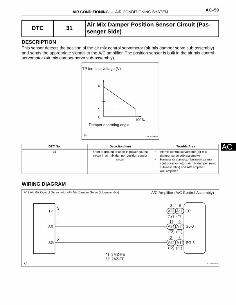
ADESCRIPTIONThis sensor detects the position of the air mix control servomotor (air mix damper servo sub-assembly) and sends the appropriate signals to the A/C amplifier. The position sensor is built in the air mix control servomotor (air mix damper servo sub-assembly).
WIRING DIAGRAM
DTC 31 Air Mix Damper Position Sensor Circuit (Pas-senger Side)
DTC No. Detection Item Trouble Area
31 Short to ground or short in power source circuit in air mix damper position sensor
circuit
• Air mix control servomotor (air mix damper servo sub-assembly)
• Harness or connector between air mix control servomotor (air mix damper servo sub-assembly) and A/C amplifier
• A/C amplifier
TP terminal voltage (V)
4
1
0100%
Damper operating angle
E109300E02
C
A/C Amplifier (A/C Control Assembly)
A11A31
A11A31
A11A31
8
11
3
6
2
9(*1)(*2)
(*1)(*2)
(*1)(*2)
A19 Air Mix Control Servomotor (Air Mix Damper Servo Sub-assembly)
1
2
3TP
S5
SG
*1: 3MZ-FE *2: 2AZ-FE
TP
S5-3
SG-3
E112594E01
AC–60 AIR CONDITIONING – AIR CONDITIONING SYSTEM
AC
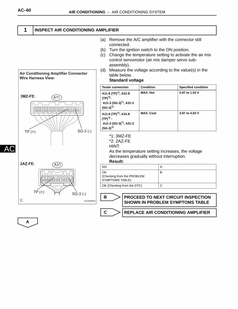
(a) Remove the A/C amplifier with the connector still connected.
(b) Turn the ignition switch to the ON position.(c) Change the temperature setting to activate the air mix
control servomotor (air mix damper servo sub-assembly).
(d) Measure the voltage according to the value(s) in the table below.Standard voltage
*1: 3MZ-FE*2: 2AZ-FEHINT:As the temperature setting increases, the voltage decreases gradually without interruption.Result:
B
C
A
1 INSPECT AIR CONDITIONING AMPLIFIER
C
Air Conditioning Amplifier Connector Wire Harness View:
3MZ-FE: A11
A312AZ-FE:
SG-3 (-)TP (+)
SG-3 (-)TP (+)
E112546E09
Tester connection Condition Specified condition
A11-6 (TP)*1, A31-8 (TP)*2- A11-3 (SG-3)*1, A31-2 (SG-3)*2
MAX. Hot 0.97 to 1.03 V
A11-6 (TP)*1, A31-8 (TP)*2 - A11-3 (SG-3)*1, A31-2 (SG-3)*2
MAX. Cool 3.97 to 4.03 V
NG A
OK(Checking from the PROBLEM SYMPTOMS TABLE)
B
OK (Checking from the DTC) C
PROCEED TO NEXT CIRCUIT INSPECTION SHOWN IN PROBLEM SYMPTOMS TABLE
REPLACE AIR CONDITIONING AMPLIFIER

AIR CONDITIONING – AIR CONDITIONING SYSTEM AC–61
C
A(a) Remove the air mix control servomotor (air mix damper servo sub-assembly).
(b) Measure the resistance according to the value(s) in the table below.Standard resistance
(c) Measure the resistance according to the value(s) in the table below.HINT:For details, regarding operation of servomotor. (See page AC-72)Standard resistance
HINT:As the air mix control servomotor (air mix damper servo sub-assembly) moves from the cool side to the warm side, the resistance decreases gradually without interruption.
NG
OK
(a) Measure the resistance according to the value(s) in the table below.
2 INSPECT AIR MIX CONTROL SERVOMOTOR (AIR MIX DAMPER SERVO SUB-ASSEMBLY)
Air Mix Control Servomotor (Air Mix Damper Servo Sub-assembly) Connector Front View:
S5SGTP
A19
E112582E04
MAX. HOT
MAX. COOL
Resistance (kΩ)
3.4 to 6.2
0.8 to 1.6
Arm position
MAX. COOL MAX. HOTE112617E01
Tester connection Condition Specified condition
A19-1 (S5) - A19-2 (SG) Always 4.2 to 6.8 kΩ
Tester connection Condition Specified condition
A19-3 (TP) - A19-2 (SG) Max. Cool 3.4 to 6.2 kΩ
A19-3 (TP) - A19-2 (SG) Max. Hot 0.8 to 1.6 kΩ
REPLACE AIR MIX CONTROL SERVOMOTOR
3 CHECK HARNESS AND CONNECTOR (AIR MIX CONTROL SERVOMOTOR - AIR CONDITIONING AMPLIFIER)

AC–62 AIR CONDITIONING – AIR CONDITIONING SYSTEM
AC
Standard resistance*1: 3MZ-FE*2: 2AZ-FE
NG
OK
Tester connection Condition Specified condition
A11-9 (S5-3)*1, A31-11 (S5-3)*2 - A19-1 (S5)
Always Below 1 Ω
A11-3 (SG-3)*1, A31-2 (SG-3)*2 - A19-2 (SG)
Always Below 1 Ω
A11-6 (TP)*1, A31-8 (TP)*2 - A19-3 (TP)
Always Below 1 Ω
A11-9 (S5-3)*1, A31-11 (S5-3)*2 -Body ground
Always 10 kΩ or higher
A11-3 (SG-3)*1, A31-2 (SG-3)*2 -Body ground
Always 10 kΩ or higher
A11-6 (TP)*1, A31-8 (TP)*2 -Body ground
Always 10 kΩ or higher
C
Air Mix Control Servomotor (Air Mix Damper Servo Sub-assembly) Connector Wire Harness View:
A19
S5 SG TP
A31A11
Air Conditioning Amplifier Connector Wire Harness View:
3MZ-FE: 2AZ-FE:
SG-3TPS5-3
S5-3TP
SG-3E112551E04
REPAIR OR REPLACE HARNESS OR CONNECTOR
REPLACE AIR CONDITIONING AMPLIFIER

AIR CONDITIONING – AIR CONDITIONING SYSTEM AC–63
C
ADESCRIPTIONThis sensor detects the position of the air inlet control servomotor (recirculation damper servo sub-assembly) and sends the appropriate signals to the A/C amplifier. The position sensor is built in the air inlet control servomotor (recirculation damper servo sub-assembly).
WIRING DIAGRAM
DTC 32 Air Inlet Damper Position Sensor Circuit
DTC No. Detection Item Trouble Area
32 Short to ground or short in power source circuit in air inlet damper position sensor circuit
• Air inlet control servomotor (recirculation damper servo sub-assembly)
• Harness or connector between air inlet control servomotor (recirculation damper servo sub-assembly) and A/C amplifier
• A/C amplifier
Voltage (V)
Damper opening angle
4.3
0.7
0 100 %
E109300E04
C
A/C Amplifier (A/C Control Assembly)
(*1)(*2)
(*1)(*2)
(*1)(*2)
A11A31
A11A31
A11A31
A18 Air Inlet Control Servomotor (Recircuration Damper Servo Sub-assembly)
TPI
S5
SG
IL1
IL1
IL1
3
2
1 6
7
8TPI
S5-2
SG-2
9
10
7
3 4
12
*1: 3MZ-FE *2: 2AZ-FE
E112595E01

AC–64 AIR CONDITIONING – AIR CONDITIONING SYSTEM
AC
(a) Remove the A/C amplifier with the connectors still connected.
(b) Turn the ignition switch to the ON position.(c) Change the RECIRC/FRESH setting to activate the air
inlet control servomotor (recirculation damper servo sub-assembly).
(d) Measure the voltage according to the value(s) in the table below.Standard voltage
*1: 3MZ-FE*2: 2AZ-FEHINT:As the recirculation damper servo sub-assembly moves from the RECIRC side to the FRESH side, the voltage decreases gradually without interruption.Result:
B
C
A
(a) Remove the air inlet control servomotor (recirculation damper servo sub-assembly).
1 INSPECT AIR CONDITIONING AMPLIFIER (TPI - SG-2)
C
Air Conditioning Amplifier Connec-tor Wire Harness View:
3MZ-FE: A11
A312AZ-FE:
SG-2 (-)TPI (+)
TPI (+) SG-2 (-)E112546E07
Tester connection Condition Specified condition
A11-7 (TPI)*1, A31-9 (TPI)*2-
A11-4 (SG-2)*1, A31-3 (SG-2)*2
RECIRC 4.27 to 4.33 V
A11-7 (TPI)*1, A31-9 (TPI)*2 -
A11-4 (SG-2)*1, A31-3 (SG-2)*2
FRESH 0.67 to 0.73 V
NG A
OK(Checking from the PROBLEM SYMPTOMS TABLE)
B
OK (Checking from the DTC) C
PROCEED TO NEXT CIRCUIT INSPECTION SHOWN IN PROBLEM SYMPTOMS TABLE
REPLACE AIR CONDITIONING AMPLIFIER
2 INSPECT AIR INLET CONTROL SERVOMOTOR (RECIRCULATION DAMPER SERVO SUB-ASSEMBLY)
AIR CONDITIONING – AIR CONDITIONING SYSTEM AC–65
C
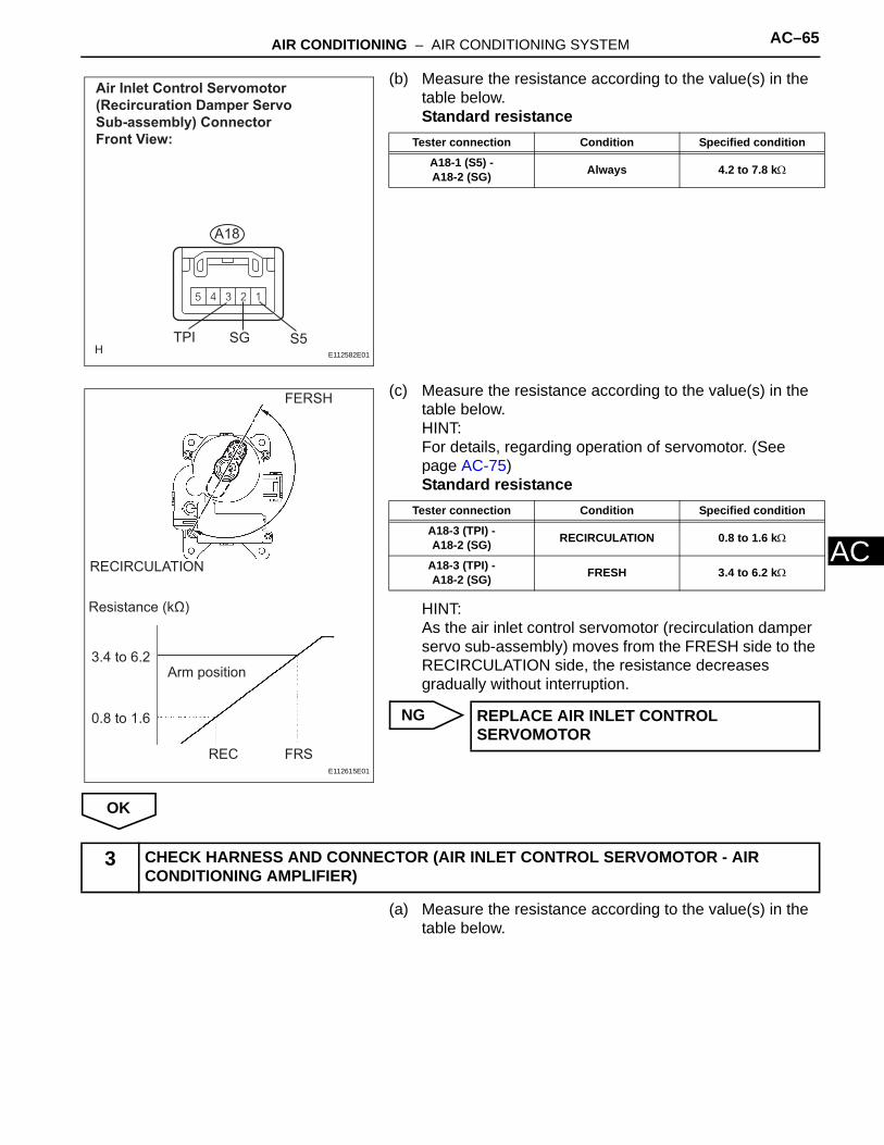
A(b) Measure the resistance according to the value(s) in the table below.Standard resistance
(c) Measure the resistance according to the value(s) in the table below.HINT:For details, regarding operation of servomotor. (See page AC-75)Standard resistance
HINT:As the air inlet control servomotor (recirculation damper servo sub-assembly) moves from the FRESH side to the RECIRCULATION side, the resistance decreases gradually without interruption.
NG
OK
(a) Measure the resistance according to the value(s) in the table below.
Air Inlet Control Servomotor (Recircuration Damper Servo Sub-assembly) Connector Front View:
A18
S5SGTPIE112582E01
Tester connection Condition Specified condition
A18-1 (S5) -A18-2 (SG) Always 4.2 to 7.8 kΩ
FERSH
RECIRCULATION
Resistance (kΩ)
3.4 to 6.2
0.8 to 1.6
REC FRS
Arm position
E112615E01
Tester connection Condition Specified condition
A18-3 (TPI) -A18-2 (SG) RECIRCULATION 0.8 to 1.6 kΩ
A18-3 (TPI) -A18-2 (SG) FRESH 3.4 to 6.2 kΩ
REPLACE AIR INLET CONTROL SERVOMOTOR
3 CHECK HARNESS AND CONNECTOR (AIR INLET CONTROL SERVOMOTOR - AIR CONDITIONING AMPLIFIER)

AC–66 AIR CONDITIONING – AIR CONDITIONING SYSTEM
AC
Standard resistance*1: 3MZ-FE*2: 2AZ-FE
NG
OK
Tester connection Condition Specified condition
A11-10 (S5-2)*1, A31-12 (S5-2)*2 -A18-1 (S5)
Always Below 1 Ω
A11-4 (SG-2)*1, A31-3 (SG-2)*2 -A18-2 (SG)
Always Below 1 Ω
A11-7 (TPI)*1, A31-9 (TPI)*2 -A18-3 (TPI)
Always Below 1 Ω
A11-10 (S5-2)*1, A31-12 (S5-2)*2 -Body ground
Always 10 kΩ or higher
A11-4 (SG-2)*1, A31-3 (SG-2)*2 -Body ground
Always 10 kΩ or higher
A11-7 (TPI)*1, A31-9 (TPI)*2 -Body ground
Always 10 kΩ or higher
C
Air Inlet Control Servomotor (Recircuration Damper Servo Sub-assembly) Connector Wire Harness View:
A18
S5 SG TPI
A31A11
Air Conditioning Amplifier Connector Wire Harness View:
3MZ-FE: 2AZ-FE:
SG-2TPIS5-2S5-2
TPISG-2
E112551E01
REPAIR OR REPLACE HARNESS OR CONNECTOR
REPLACE AIR CONDITIONING AMPLIFIER

AIR CONDITIONING – AIR CONDITIONING SYSTEM AC–67
C
ADESCRIPTIONThis sensor detects the position of the air outlet control servomotor (mode damper servo sub-assembly) and sends the appropriate signals to the A/C amplifier. The position sensor is built in the air outlet control servomotor (mode damper servo sub-assembly).
WIRING DIAGRAM
DTC 33 Air Outlet Damper Position Sensor Circuit
DTC No. Detection Item Trouble Area
33 Short to ground or short in power source circuit in air outlet damper position sensor circuit
• Air outlet control servomotor (mode damper servo sub-assembly)
• Harness or connector between air outlet control servomotor (mode damper servo sub-assembly) and A/C amplifier
• A/C amplifier
Voltage (V)
Damper opening angle
4
1
0 100 %
E109300E01
C
A/C Amplifier (A/C Control Assembly)
(*1)(*2)
(*1)(*2)
(*1)(*2)
A11A31
A11A31
A11A311
2
3
A20 Air Outlet Control Servomotor (Mode Damper Servo Sub-assembly)
PT
VZ
GND IG3
IG3
IG3
8
9
10
TPO
S5-1
SG-1
810
57
1 2
*1: 3MZ-FE *2: 2AZ-FE
E112596E01

AC–68 AIR CONDITIONING – AIR CONDITIONING SYSTEM
AC
(a) Remove the A/C amplifier with the connectors still connected.
(b) Turn the ignition switch to the ON position.(c) Change the mode setting to activate the mode air outlet
control servomotor (damper servo sub-assembly).(d) Measure the voltage according to the value(s) in the
table below.Standard voltage
*1: 3MZ-FE*2: 2AZ-FEHINT:As the air outlet control servomotor (mode damper servo sub-assembly) moves from the FACE side to the DEF side, the voltage decreases gradually without interruption.Result:
B
C
A
(a) Remove the air outlet control servomotor (mode damper servo sub-assembly).
1 INSPECT AIR CONDITIONING AMPLIFIER (TPO - SG-1)
C
Air Conditioning Amplifier Connector Wire Harness View:
3MZ-FE: A11
A312AZ-FE:
SG-1 (-)
SG-1 (-)TPO(+)
TPO (+)
E112546E08
Tester connection Condition Specified condition
A11-5 (TPO)*1, A31-7 (TPO)*2 -
A11-2 (SG-1)*1, A31-1 (SG-1)*2
FACE 3.97 to 4.03 V
A11-5 (TPO)*1, A31-7 (TPO)*2 -
A11-2 (SG-1)*1, A31-1 (SG-1)*2
DEF 0.97 to 1.03 V
NG A
OK(Checking from the PROBLEM SYMPTOMS TABLE)
B
OK (Checking from the DTC) C
PROCEED TO NEXT CIRCUIT INSPECTION SHOWN IN PROBLEM SYMPTOMS TABLE
REPLACE AIR CONDITIONING AMPLIFIER
2 INSPECT AIR OUTLET CONTROL SERVOMOTOR (MODE DAMPER SERVO SUB-ASSEMBLY)

AIR CONDITIONING – AIR CONDITIONING SYSTEM AC–69
C
A(b) Measure the resistance according to the value(s) in the table below.Standard resistance
(c) Measure the resistance according to the value(s) in the table below.HINT:For details, regarding operation of the servomotor. (See page AC-79)Standard resistance
HINT:As the air outlet control servomotor (mode damper servo sub-assembly) moves from the DEF side to the FACE side, the resistance decreases gradually without interruption.
NG
OK
(a) Measure the resistance according to the value(s) in the table below.
Air Outlet Control Servomotor (Mode Damper Servo Sub-assembly) Connector Front View:
GNDVZPT
A20
E112582E02
Tester connection Condition Specified condition
A20-2 (VZ) -A20-1 (GND) Always 4.2 to 7.8 kΩ
FACE
DEF
Resistance (kΩ)
3.4 to 6.2
0.8 to 1.6
FACEDEF
Air position
E112616E01
Tester connection Condition Specified condition
A20-3 (PT) -A20-1 (GND) DEF 3.4 to 6.2 kΩ
A20-3 (PT) -A20-1 (GND) FACE 0.8 to 1.6 kΩ
REPLACE AIR OUTLET CONTROL SERVOMOTOR
3 CHECK HARNESS AND CONNECTOR (AIR OUTLET CONTROL SERVOMOTOR - AIR CONDITIONING AMPLIFIER)

AC–70 AIR CONDITIONING – AIR CONDITIONING SYSTEM
AC
Standard resistance*1: 3MZ-FE*2: 2AZ-FE
NG
OK
Tester connection Condition Specified condition
A11-8 (S5-1)*1, A31-10 (S5-1)*2 -A20-2 (VZ)
Always Below 1 Ω
A11-2 (SG-1)*1, A31-1 (SG-1)*2 -A20-1 (GND)
Always Below 1 Ω
A11-5 (TPO)*1, A31-7 (TPO)*2 -A20-3 (PT)
Always Below 1 Ω
A11-8 (S5-1)*1, A31-10 (S5-1)*2 -Body ground
Always 10 kΩ or higher
A11-2 (SG-1)*1, A31-1 (SG-1)*2 -Body ground
Always 10 kΩ or higher
A11-5 (TPO)*1, A31-7 (TPO)*2 -Body ground
Always 10 kΩ or higher
C
Air Outlet Control Servomotor (Mode Damper Servo Sub-assembly) Connector Wire Harness View:
GND VZ PT
A20
A31A11
Air Conditioning Amplifier Connector Wire Harness View:
3MZ-FE: 2AZ-FE:
TPOS5-1SG-1
S5-1TPO SG-1
E112551E02
REPAIR OR REPLACE HARNESS OR CONNECTOR
REPLACE AIR CONDITIONING AMPLIFIER

AIR CONDITIONING – AIR CONDITIONING SYSTEM AC–71
C
ADESCRIPTIONThe air mix control servomotor (air mix damper servo sub-assembly) is controlled by the A/C amplifier. Air flow temperature changes when moving the air mix damper to the target point. The target point can be detected with the air mix damper position sensor.
WIRING DIAGRAM
(a) Set the actuator check mode (See page AC-14). (b) Press the DEF switch to change to the step operation.(c) Check the air flow temperature by hand.
DTC 41 Air Mix Damper Control Servomotor Circuit (Passenger Side)
DTC No. Detection Item Trouble Area
41 Air mix damper position sensor value does not change even if air conditioner amplifier assembly operates air mix servomotor
• Air mix control servomotor (air mix damper servo sub-assembly)
• Harness or connector between air mix control servomotor (air mix damper servo sub-assembly) and A/C amplifier
• A/C amplifier
1 PERFORM ACTUATOR CHECK
C
A/C Amplifier (A/C Control Assembly)
A11A31
A11A31
(*1)(*2)
(*1)(*2)
13
1417
18
A19 Air Mix Control Servomotor (Air Mix Damper Servo Sub-assembly)
5
4
MH
MC
AMH
AMC
*1: 3MZ-FE *2: 2AZ-FE
E112597E01
Display Code Air mix damper position
0 COOL side (0% open)
1 COOL side (0% open)
2 COOL side (0% open)
3 COOL side (0% open)
4 COOL/HOT (50% open)
5 COOL/HOT (50% open)
6 HOT side (100% open)
7 HOT side (100% open)
8 HOT side (100% open)
9 HOT side (100% open)

AC–72 AIR CONDITIONING – AIR CONDITIONING SYSTEM
AC
OK:Air flow temperature changes in accordance with each display code.
Result:
B
C
A
(a) Remove the air mix control servomotor (air mix damper servo sub-assembly).
(b) Connect the positive (+) lead from the battery to terminal 5 and negative (-) lead to terminal 4, then check that the lever turns to the "MAX. HOT" position smoothly.
(c) Connect the positive (+) lead from the battery to terminal 4 and negative (-) lead to terminal 5, then check that the lever turns to the "MAX. COOL" position smoothly.
NG
OK
(a) Measure the resistance according to the value(s) in the table below.
NG A
OK(Checking from the PROBLEM SYMPTOMS TABLE)
B
OK (Checking from the DTC) C
PROCEED TO NEXT CIRCUIT INSPECTION SHOWN IN PROBLEM SYMPTOMS TABLE
REPLACE AIR CONDITIONING AMPLIFIER
2 INSPECT AIR MIX CONTROL SERVOMOTOR (AIR MIX DAMPER SERVO SUB-ASSEMBLY)
Air Mix Control Servomotor (Air Mix Damper Servo Sub-assembly) Connector Front View:
A19
MHOT MCOOLE112582E06
MAX. HOT
MAX. COOL
I036818E01
REPLACE AIR MIX CONTROL SERVOMOTOR
3 CHECK HARNESS AND CONNECTOR (AIR MIX CONTROL SERVOMOTOR - AIR CONDITIONING AMPLIFIER)
AIR CONDITIONING – AIR CONDITIONING SYSTEM AC–73
C
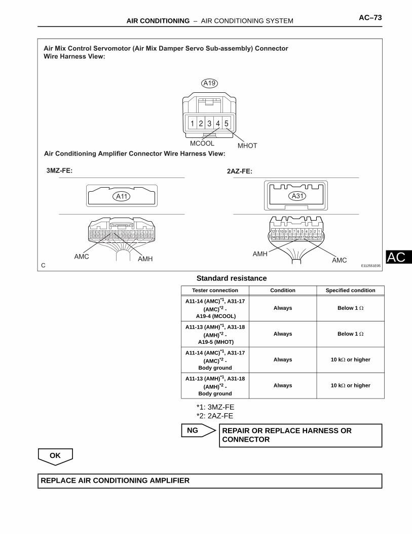
AStandard resistance*1: 3MZ-FE*2: 2AZ-FE
NG
OK
C
Air Mix Control Servomotor (Air Mix Damper Servo Sub-assembly) Connector Wire Harness View:
A19
A31A11
Air Conditioning Amplifier Connector Wire Harness View:
3MZ-FE: 2AZ-FE:
AMCAMH
AMHAMC
MHOTMCOOL
E112551E05
Tester connection Condition Specified condition
A11-14 (AMC)*1, A31-17 (AMC)*2 -
A19-4 (MCOOL)Always Below 1 Ω
A11-13 (AMH)*1, A31-18 (AMH)*2 -
A19-5 (MHOT)Always Below 1 Ω
A11-14 (AMC)*1, A31-17 (AMC)*2 -
Body groundAlways 10 kΩ or higher
A11-13 (AMH)*1, A31-18 (AMH)*2 -
Body groundAlways 10 kΩ or higher
REPAIR OR REPLACE HARNESS OR CONNECTOR
REPLACE AIR CONDITIONING AMPLIFIER
AC–74 AIR CONDITIONING – AIR CONDITIONING SYSTEM
AC
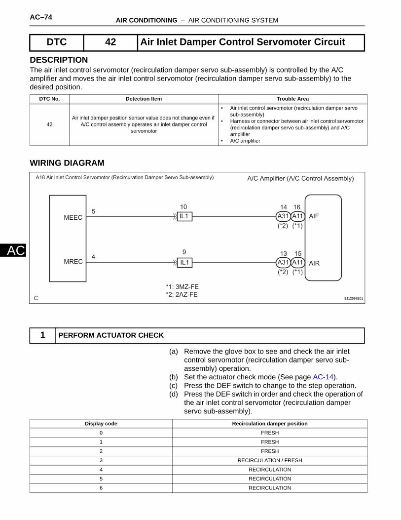
DESCRIPTIONThe air inlet control servomotor (recirculation damper servo sub-assembly) is controlled by the A/C amplifier and moves the air inlet control servomotor (recirculation damper servo sub-assembly) to the desired position.
WIRING DIAGRAM
(a) Remove the glove box to see and check the air inlet control servomotor (recirculation damper servo sub-assembly) operation.
(b) Set the actuator check mode (See page AC-14). (c) Press the DEF switch to change to the step operation.(d) Press the DEF switch in order and check the operation of
the air inlet control servomotor (recirculation damper servo sub-assembly).
DTC 42 Air Inlet Damper Control Servomoter Circuit
DTC No. Detection Item Trouble Area
42Air inlet damper position sensor value does not change even if
A/C control assembly operates air inlet damper control servomotor
• Air inlet control servomotor (recirculation damper servo sub-assembly)
• Harness or connector between air inlet control servomotor (recirculation damper servo sub-assembly) and A/C amplifier
• A/C amplifier
1 PERFORM ACTUATOR CHECK
C
A/C Amplifier (A/C Control Assembly)A18 Air Inlet Control Servomotor (Recircuration Damper Servo Sub-assembly)
A11A31
A11A31
(*1)(*2)
(*1)(*2)
9
10IL1
IL1
5
4
MEEC
MREC
AIF
AIR
*1: 3MZ-FE *2: 2AZ-FE
16
15
14
13
E112598E01
Display code Recirculation damper position
0 FRESH
1 FRESH
2 FRESH
3 RECIRCULATION / FRESH
4 RECIRCULATION
5 RECIRCULATION
6 RECIRCULATION

AIR CONDITIONING – AIR CONDITIONING SYSTEM AC–75
C
AOK:Recirculation damper position changes in accordance with each display code.
Result:
B
C
A
(a) Remove the air inlet control servomotor (recirculation damper servo sub-assembly).
7 RECIRCULATION
8 RECIRCULATION
9 RECIRCULATION
Display code Recirculation damper position
NG A
OK(Checking from the PROBLEM SYMPTOMS TABLE)
B
OK (Checking from the DTC) C
PROCEED TO NEXT CIRCUIT INSPECTION SHOWN IN PROBLEM SYMPTOMS TABLE
REPLACE AIR CONDITIONING AMPLIFIER
2 INSPECT AIR INLET CONTROL SERVOMOTOR (RECIRCULATION DAMPER SERVO SUB-ASSEMBLY)
Air Inlet Control Servomotor (Recircuration Damper Servo Sub-assembly) Connector Front View:
A18
MRECMEECE112582E07
AC–76 AIR CONDITIONING – AIR CONDITIONING SYSTEM
AC
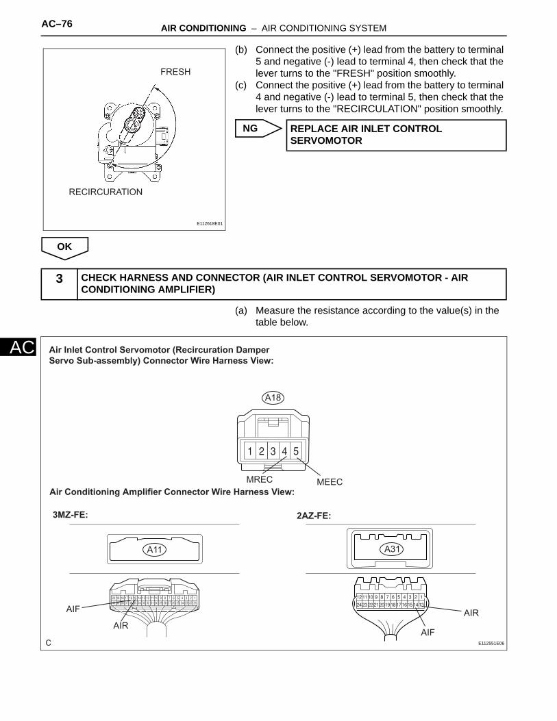
(b) Connect the positive (+) lead from the battery to terminal 5 and negative (-) lead to terminal 4, then check that the lever turns to the "FRESH" position smoothly.
(c) Connect the positive (+) lead from the battery to terminal 4 and negative (-) lead to terminal 5, then check that the lever turns to the "RECIRCULATION" position smoothly.
NG
OK
(a) Measure the resistance according to the value(s) in the table below.
FRESH
RECIRCURATION
E112618E01
REPLACE AIR INLET CONTROL SERVOMOTOR
3 CHECK HARNESS AND CONNECTOR (AIR INLET CONTROL SERVOMOTOR - AIR CONDITIONING AMPLIFIER)
C
Air Inlet Control Servomotor (Recircuration Damper Servo Sub-assembly) Connector Wire Harness View:
A18
MREC MEEC
A31A11
Air Conditioning Amplifier Connector Wire Harness View:
3MZ-FE: 2AZ-FE:
AIF
AIRAIR
AIFE112551E06

AIR CONDITIONING – AIR CONDITIONING SYSTEM AC–77
C
AStandard resistance
*1: 3MZ-FE*2: 2AZ-FE
NG
OK
Tester connection Condition Specified condition
A11-16 (AIF)*1, A31-14 (AIF)*2 -
A18-5 (MEEC)Always Below 1 Ω
A11-15 (AIR)*1, A31-13 (AIR)*2 -
A18-4 (MREC)Always Below 1 Ω
A11-16 (AIF)*1, A31-14 (AIF)*2 -
Body groundAlways 10 kΩ or higher
A11-15 (AIR)*1, A31-13 (AIR)*2 -
Body groundAlways 10 kΩ or higher
REPAIR OR REPLACE HARNESS OR CONNECTOR
REPLACE AIR CONDITIONING AMPLIFIER

AC–78 AIR CONDITIONING – AIR CONDITIONING SYSTEM
AC
DESCRIPTIONThis circuit turns the servomotor and changes each damper position by receiving the signals from the A/C amplifier assembly. When the AUTO switch is on, the A/C amplifier changes the mode between "FACE", "BI-LEVEL" and "FOOT" according to the temperature setting.
WIRING DIAGRAM
(a) Warm up the engine.(b) Set the actuator check mode (See page AC-14). (c) Press the DEF switch to change to the step operation.(d) Press the DEF switch and check the air flow by hand.
DTC 43 Air Outlet Damper Control Servomotor Circuit
DTC No. Detection Item Trouble Area
43Air outlet damper position sensor value does not change even if air conditioner amplifier operates air outlet damper control
servomotor
• Air outlet control servomotor (mode damper servo sub-assembly)
• Harness or connector between air outlet control servomotor (mode damper servo sub-assembly) and A/C amplifier
• A/C amplifier
1 PERFORM ACTUATOR CHECK
C
A/C Amplifier (A/C Control Assembly)A20 Air Outlet Control Servomotor (Mode Damper Servo Sub-assembly)
A11A31
A11A31(*1)(*2)
(*1)(*2)
11
1215
16IG3
IG3
6
7
5
4
MFACE
MDEF
AOF
AOD
*1: 3MZ-FE *2: 2AZ-FE
E112599E01
Display code Air flow position
0 FACE
1 FACE
2 FACE
3 FACE
4 FACE
5 BI-LEVEL
6 FOOT (MANUAL)
7 FOOT (AUTO)
8 FOOT/DEF
9 DEF
AIR CONDITIONING – AIR CONDITIONING SYSTEM AC–79
C
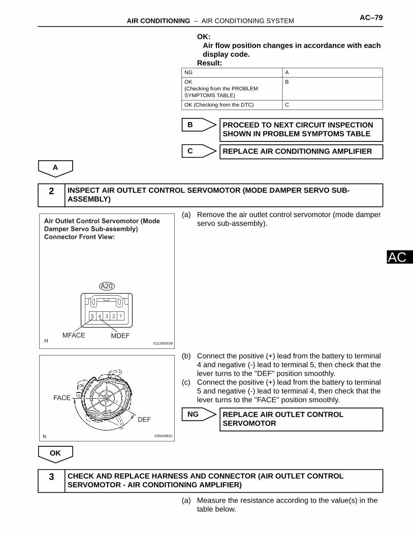
AOK:Air flow position changes in accordance with each display code.
Result:
B
C
A
(a) Remove the air outlet control servomotor (mode damper servo sub-assembly).
(b) Connect the positive (+) lead from the battery to terminal 4 and negative (-) lead to terminal 5, then check that the lever turns to the "DEF" position smoothly.
(c) Connect the positive (+) lead from the battery to terminal 5 and negative (-) lead to terminal 4, then check that the lever turns to the "FACE" position smoothly.
NG
OK
(a) Measure the resistance according to the value(s) in the table below.
NG A
OK(Checking from the PROBLEM SYMPTOMS TABLE)
B
OK (Checking from the DTC) C
PROCEED TO NEXT CIRCUIT INSPECTION SHOWN IN PROBLEM SYMPTOMS TABLE
REPLACE AIR CONDITIONING AMPLIFIER
2 INSPECT AIR OUTLET CONTROL SERVOMOTOR (MODE DAMPER SERVO SUB-ASSEMBLY)
Air Outlet Control Servomotor (Mode Damper Servo Sub-assembly) Connector Front View:
MDEFMFACE
A20
E112582E08
DEF
FACE
I035439E01
REPLACE AIR OUTLET CONTROL SERVOMOTOR
3 CHECK AND REPLACE HARNESS AND CONNECTOR (AIR OUTLET CONTROL SERVOMOTOR - AIR CONDITIONING AMPLIFIER)

AC–80 AIR CONDITIONING – AIR CONDITIONING SYSTEM
AC
Standard resistance*1: 3MZ-FE*2: 2AZ-FE
NG
OK
C
Air Outlet Control Servomotor (Mode Damper Servo Sub-assembly) Connector Wire Harness View:
A20
A31A11
Air Conditioning Amplifier Connector Wire Harness View:
3MZ-FE: 2AZ-FE:
AOFAOD
MFACEMDEF
AODAOF
E112551E07
Tester connection Condition Specified condition
A11-11 (AOF)*1, A31-16 (AOF)*2-
A20-5 (MFACE)Always Below 1 Ω
A11-12 (AOD)*1, A31-15 (AOD)*2 -
A20-4 (MDEF)Always Below 1 Ω
A11-11 (AOF)*1, A31-16 (AOF)*2 -
Body groundAlways 10 kΩ or higher
A11-12 (AOD)*1, A31-15 (AOD)*2 -
Body groundAlways 10 kΩ or higher
REPAIR OR REPLACE HARNESS OR CONNECTOR
REPLACE AIR CONDITIONING AMPLIFIER

AC–12 AIR CONDITIONING – AIR CONDITIONING SYSTEM
AC
SYSTEM DESCRIPTION1. GENERAL
(a) The air conditioning system in the '04 CAMRY SOLARA has the following features:• A compact, lightweight, and low-noise swash
plate type compressor has been adopted.• The air conditioning ECU is equipped with a self-
diagnosis function. If there is a malfunction in the system, it stores the DTCs (Diagnostic Trouble Codes) in its memory and the air conditioning switch indicator blinks.
• The compressor and water temperature sensor are connected to the ECM.
• The A/C amplifier receives the vehicle speed signal from the combination meter.
2. MODEL POSITION AND DAMPER OPERATION
Control Damper Control Position Damper Position Operation
Air Inlet Control Damper FRESH A Brings in fresh air.
RECIRC B Recirculates internal air.
Center Defroster
AB
C
D
E
F GH
I
J
K
LM
N
O
P
QR
Heater CoreEvaporatorBlower Motor
Fresh Air
Side Defroster Side Defroster
Side RegisterSide RegisterCenter Register
Rear Footwell Register Duct
Footwell Register Duct
Footwell Register Duct
Recirc. Air
E112567E01

AIR CONDITIONING – AIR CONDITIONING SYSTEM AC–13
C
AAir Mix Control Damper MAX. COLD to MAX. HOT TEMP. SETTING18°C (64.4°F) to 32°C (89.6°F)
C to D to E Varies the mixture ratio of the fresh air and the recirculation air in order to regulate the temperature continuously from HOT to COOL.
Mode Control Damper DEF F,K,L,O,R Defrosts the windshield through the center defroster, side defrosters, and side registers.
FOOT/DEF G,K,L,O,Q Defrosts the windshield through the center defroster, side defrosters, and side registers, while air is also blown out from the front and rear footwell register duct.
FOOT H,K,L,O,P Air blows out of the front and rear footwell register ducts, and side registers. In addition, air blows out slightly from the center defroster and side defrosters.
BI-LEVEL I,J,M,N,P Air blows out of the center register, side registers and footwell register ducts.
FACE I,J,M,N,R Air blows out of the center register and side registers
Control Damper Control Position Damper Position Operation

AC–14 AIR CONDITIONING – AIR CONDITIONING SYSTEM
AC
3. AIR OUTLETS AND AIR VOLUME RATIONS
Air Outer Mode A B C D
Center Face Side Face Foot Defroster
FACE
BI-LEVEL
FOOT
FOOT/DEF
DEF
D
AB
C
D
D
D D
C
B
C
C
A
E112568E02

AIR CONDITIONING – AIR CONDITIONING SYSTEM AC–81
C
ADESCRIPTIONThe A/C amplifier monitors signals from the speed sensor via the combination meter. The A/C amplifier assembly uses these signals to revise the ambient temperature sensor signal.Check that the speedometer in the combination meter operates normally before inspecting the vehicle speed signal circuit.If the meter does not operate normally, refer to the combination meter system (See page ME-10).
WIRING DIAGRAM
(a) Remove the A/C amplifier assembly with the connectors still connected.
(b) Move the shift lever to the Neutral position.(c) Lift up the vehicle.(d) Turn the ignition switch to the ON position.
Vehicle Speed Signal Circuit
1 INSPECT AIR CONDITIONING AMPLIFIER (SPD)
C
A/C Amplifier (A/C Control Assembly)
A11A32(*1)(*2)
2 18
Combination Meter
3A3A92 32
C7
C7
36
35
SPD
From Skid Comtrol ECU with Actuator
*1: 3MZ-FE *2: 2AZ-FE
Passenger Side J/B
E112604E01
AC–82 AIR CONDITIONING – AIR CONDITIONING SYSTEM
AC
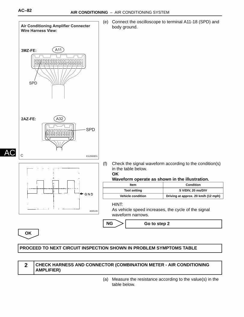
(e) Connect the oscilloscope to terminal A11-18 (SPD) and body ground.
(f) Check the signal waveform according to the condition(s) in the table below.OKWaveform operate as shown in the illustration.
HINT:As vehicle speed increases, the cycle of the signal waveform narrows.
NG
OK
(a) Measure the resistance according to the value(s) in the table below.
C
Air Conditioning Amplifier Connecter Wire Harness View:
A32
SPD
SPD
A113MZ-FE:
2AZ-FE:
E112583E01
A005135
Item Condition
Tool setting 5 V/DIV, 20 ms/DIV
Vehicle condition Driving at approx. 20 km/h (12 mph)
Go to step 2
PROCEED TO NEXT CIRCUIT INSPECTION SHOWN IN PROBLEM SYMPTOMS TABLE
2 CHECK HARNESS AND CONNECTOR (COMBINATION METER - AIR CONDITIONING AMPLIFIER)

AIR CONDITIONING – AIR CONDITIONING SYSTEM AC–83
C
AStandard resistance*1: 3MZ-FE*2: 2AZ-FE
NG
OK
C
Combination Meter Assembly Connector Front View:
C7
A32A11
Air Conditioning Amplifier Connector Wire Harness View:
3MZ-FE: 2AZ-FE:
SPDSPD
C7-36
E112554E01
Tester connection Condition Specified condition
C7-36 - A11-18 (SPD)*1, A32-2 (SPD)*2
Always Below 1 Ω
A11-18 (SPD)*1, A32-2 (SPD)*2 -
Body groundAlways 10 kΩ or higher
REPAIR OR REPLACE HARNESS OR CONNECTOR
GO TO COMBINATION METER SYSTEM

AC–84 AIR CONDITIONING – AIR CONDITIONING SYSTEM
AC
DESCRIPTIONThe blower motor is operated by signals from the A/C amplifier assembly. Blower motor speed signals are transmitted by changes in the duty ratio.Duty RatioThe duty ratio is the ratio of the period of continuity in one cycle. For example, A is the period of continuity in one cycle, and B is the period of non-continuity. The blower motor controller controls the blower motor speed.
WIRING DIAGRAM
Blower Motor Circuit
Blower Level
HI
M1
M2
LO
0 30 43 67 100
Duty Ratio =A + B
A100 (%)
A
BON
OFF1 cycle
E110709E02
C
A/C Amplifier (A/C Control Assembly)
A11A32(*1)(*2)
2
3
IN
II1
II11
2
3
4M1
2
II1
IG2 From Heater Relay
B3 Blower MotorB4 Blower Motor Controller
VM
+B
SI
GND
BLW
*1: 3MZ-FE *2: 2AZ-FE
12 31
2 1
E112603E01

AIR CONDITIONING – AIR CONDITIONING SYSTEM AC–85
C
A(a) Set the actuator check mode (See page AC-14).(b) Press the blower switch to change to the step operation.(c) Check the air flow level by hand.
OK:Blower level changes in accordance with each display code.
NG
OK
(a) Measure the resistance according to the value(s) in the table below.
1 PERFORM ACTUATOR CHECK
Display Code Blower level
0 0
1 1
2 14
3 14
4 14
5 14
6 14
7 14
8 14
9 31
Go to step 2
PROCEED TO NEXT CIRCUIT INSPECTION SHOWN IN PROBLEM SYMPTOMS TABLE
2 CHECK HARNESS AND CONNECTOR (BLOWER MOTOR CONTROLLER - A/C AMPLIFIER)

AC–86 AIR CONDITIONING – AIR CONDITIONING SYSTEM
AC
Standard resistance*1: 3MZ-FE*2: 2AZ-FE
NG
OK
C
Blower Motor Controller Connector Front View:
B4
A32A11
Air Conditioning Amplifier Connector Wire Harness View:
3MZ-FE: 2AZ-FE:
BLW BLW
SI
E112553E01
Tester connection Condition Specified condition
A11-31 (BLW)*1, A32-12 (BLW)*2 - B4-2 (SI)
Always Below 1 Ω
A11-31 (BLW)*1, A32-12 (BLW)*2 -
Body groundAlways 10 kΩ or higher
REPAIR OR REPLACE HARNESS OR CONNECTOR
AIR CONDITIONING – AIR CONDITIONING SYSTEM AC–87
C
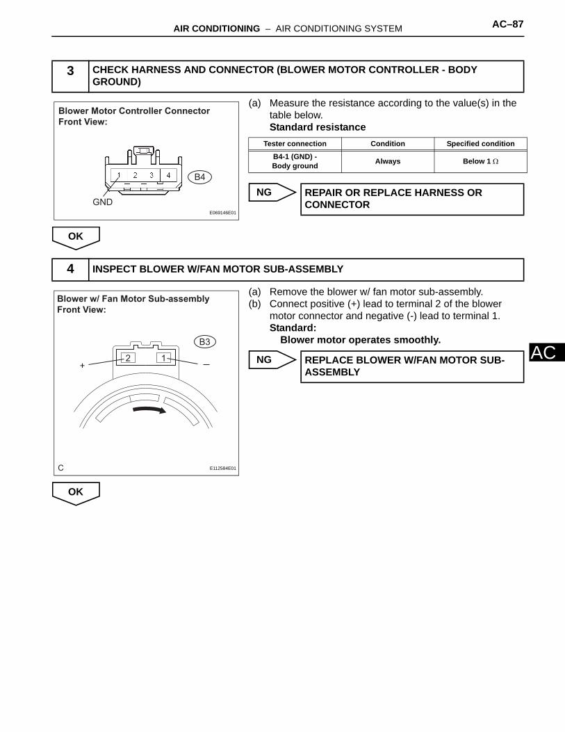
A(a) Measure the resistance according to the value(s) in the table below.Standard resistance
NG
OK
(a) Remove the blower w/ fan motor sub-assembly.(b) Connect positive (+) lead to terminal 2 of the blower
motor connector and negative (-) lead to terminal 1.Standard:
Blower motor operates smoothly.
NG
OK
3 CHECK HARNESS AND CONNECTOR (BLOWER MOTOR CONTROLLER - BODY GROUND)
Blower Motor Controller Connector Front View:
B4
GNDE069146E01
Tester connection Condition Specified condition
B4-1 (GND) - Body ground Always Below 1 Ω
REPAIR OR REPLACE HARNESS OR CONNECTOR
4 INSPECT BLOWER W/FAN MOTOR SUB-ASSEMBLY
C
Blower w/ Fan Motor Sub-assembly Front View:
B3
+
E112584E01
REPLACE BLOWER W/FAN MOTOR SUB-ASSEMBLY

AC–88 AIR CONDITIONING – AIR CONDITIONING SYSTEM
AC
(a) Measure the resistance according to the value(s) in the table below.Standard resistance
NG
OK
5 CHECK INSTRUMENT PANEL WIRE NO.3
Instrument Panel Wire No.3 Connector Front View:
Instrument Panel Wire No.3 Connector Front View:
Instrument Panel Wire No.3 Connector Front View:
Wire to Wire
II1
B4
B3
I036239E01
Tester connection Condition Specified condition
II1-1 - B4-1 Always Below 1 Ω
II1-3 - B3-1 Always Below 1 Ω
REPAIR OR REPLACE INSTRUMENT PANEL WIRE NO.3

AIR CONDITIONING – AIR CONDITIONING SYSTEM AC–89
C
A(a) Measure the resistance according to the value(s) in the table below.Standard resistance
NG
OK
6 CHECK HARNESS AND CONNECTOR (BLOWER MOTOR CONTROLLER - BLOWER MOTOR)
B4
Blower Motor Controller Connector Front View:
Blower Motor Controller Connector Front View:
B3
VM
+B
I036240E01
Tester connection Condition Specified condition
B4-4 (VM) - B3-1 Always Below 1 Ω
B4-3 (+B) - Body ground Always Below 1 Ω
REPAIR OR REPLACE HARNESS OR CONNECTOR

AC–90 AIR CONDITIONING – AIR CONDITIONING SYSTEM
AC
(a) Remove the A/C amplifier with the connectors still connected.
(b) Turn the ignition switch to the ON position.(c) Turn the blower switch on (Lo).
(d) Measure the waveform between terminal BLW (A11-31) of the A/C amplifier and body ground.OK:
Waveform operate as shown in the illustration.HINT:Waveform varies with the blower level.
NG
OK
7 INSPECT AIR CONDITIONING AMPLIFIER (BLW - BODY GROUND)
C
Air Conditioning Amplifier Connecter Wire Harness View:
A32
BLW
BLW
A113MZ-FE:
2AZ-FE:
E112583E04
500 msec./ Division
2 V/ Division
GND
E108906E12
REPLACE AIR CONDITIONING AMPLIFIER
REPLACE BLOWER MOTOR CONTROL

AIR CONDITIONING – AIR CONDITIONING SYSTEM AC–91
C
ADESCRIPTIONThe A/C amplifier outputs the magnetic clutch ON signal from terminal AC1 to the ECM receives this signal, it sends a signal from terminal ACMG (MGC) and switches the magnetic clutch relay ON, thus turning on the magnetic clutch.
WIRING DIAGRAM
3MZ-FE:
(a) Connect the intelligent tester to the DLC3.
Compressor Circuit
1 READ VALUE OF INTELLIGENT TESTER
C
A/C Amplifier (A/C Control Assembly)
A11A32
A11
A11
A32
A32
E5
E5
E5
E5
E5
E5
IK1 IK2
IK1
IK1
IK2
(*1)(*2)1 (*1) 1 (*2) 13 36
38
17
39
16
(*1)
(*1)
(*2)
(*2)
8
3
6 (*2)
(*1)
(*1)
32
24
33
25
31
(*1)
(*1)
(*1)
(*2)
(*2)
(*1)2IG5
Diode (A/C No.1)
328
1
11
1
MG CLT Relay
2
3
1
5
Engine Room J/B
1J 1L3
39
A2 A/C Magnetic Clutch
ECM
*1: 3MZ-FE *2: 2AZ-FE
THE
AC1
ACLD
ACT
A/CS
ACMG
AC1
ACT
A/CS
MGC
A/CI
Engine Room R/B
From HTR Relay
E112605E01

AC–92 AIR CONDITIONING – AIR CONDITIONING SYSTEM
AC
(b) Turn the ignition switch to the ON position and turn the intelligent tester main switch on.
(c) Select the items below in the DATA LIST, and read the displays on the intelligent tester.ENGINE AND ECT / ALL:
NG
OK
(a) Connect the intelligent tester to the DLC3.(b) Turn the ignition switch to the ON position and turn the
intelligent tester main switch on.(c) Select the item below in the ACTIVE TEST and then
check that the relay operates.ENGINE AND ECT / ALL:
NG
OK
(a) Remove the relay (MG CLT relay) from the engine room R/B.
(b) Measure the resistance according to the value(s) in the table belowStandard resistance
NG
OK
(a) Remove the ECM.
Item Measurement Item/Display (Range) Normal Condition Diagnostic Note
A/C SIG A/C signal/ ON or OFF A/C ON: ON -
A/C MAG CLUTCH A/C clutch/ ON or OFF A/C clutch ON: ON -
Go to step 9
2 PERFORM ACTIVE TEST USING INTELLIGENT TESTER
Item Test Details/Display (Range) Diagnostic Note
A/C MAG CLUTCH Magnetic clutch relay / OFF, ON Operating sound can be heard
Go to step 3
PROCEED TO NEXT CIRCUIT INSPECTION SHOWN IN PROBLEM SYMPTOMS TABLE
3 INSPECT MAGNETIC CLUTCH RELAY
1
2 3
5
1 2
35
Z018060E01
Tester connection Condition Specified condition
3 - 5 Always 10 kΩ or higher
3 - 5When battery voltage applied to terminals 1
and 2Below 1 Ω
REPLACE MAGNETIC CLUTCH RELAY
4 INSPECT ECM (ACMG - BODY GROUND)

AIR CONDITIONING – AIR CONDITIONING SYSTEM AC–93
C
A(b) Disconnect the connector from the ECM.(c) Start the engine and turn the A/C switch on.(d) Measure the voltage according to the value(s) in the
table below.Standard voltage
NG
OK
(a) Remove the ECM with the connectors still connected.(b) Start the engine and turn the A/C switch on.(c) Measure the voltage according to the value(s) in the
table below.Standard voltage
NG
OK
(a) Disconnect the connector from the magnetic clutch assembly.
C
ECM Connector Wire Harness View:
E5
ACMG
E112606E01
Tester connection Condition Specified condition
E5-2 (ACMG) - Body ground Always 10 to 14 V
REPAIR OR REPLACE HARNESS OR CONNECTOR
5 INSPECT ECM (ACMG - BODY GROUND)
C
ECM Connector Wire Harness View:
E5
ACMG
E112607E01
Tester connection Condition Specified condition
E5-2 (ACMG) - Body ground A/C switch OFF 10 to 14 V
E5-2 (ACMG) - Body ground A/C switch ON Below 1 V
Go to step 9
6 INSPECT MAGNETIC CLUTCH ASSEMBLY

AC–94 AIR CONDITIONING – AIR CONDITIONING SYSTEM
AC
(b) Connect the positive (+) lead from the battery to terminal 3 and negative (-) lead to body ground, then check that the magnetic clutch assembly is engaged.
NG
OK
(a) Measure the voltage according to the value(s) in the table below.Standard voltage
NG
OK
(a) Disconnect the connector from ECM.
Magnetic Clutch Assembly Connector Front View:
A2
E112579E03
REPLACE MAGNETIC CLUTCH ASSEMBLY
7 CHECK HARNESS AND CONNECTOR (MAGNET CLUTCH ASSEMBLY - BODY GROUND)
Magnetic Clutch Assembly Connector Wire Harness View:
A2
E112585E01
Tester connection Condition Specified condition
E5-2 (ACMG) - A2-3 A/C switch ON 10 to 14 V
REPAIR OR REPLACE HARNESS OR CONNECTOR
8 CHECK HARNESS AND CONNECTOR (ECM - MAGNET CLUTCH ASSEMBLY)

AIR CONDITIONING – AIR CONDITIONING SYSTEM AC–95
C
A(b) Measure the voltage according to the value(s) in the table below.Standard voltage
NG
OK
(a) Disconnect the connector from the ECU.
C
ECM Connector Wire Harness View:
Magnetic Clutch Assembly Connector Waire Harness View:
ACMG
E5
A2
E112608E02
Tester connection Condition Specified condition
E5-2 (ACMG) - A2-3 A/C switch ON 10 to 14 V
REPAIR OR REPLACE HARNESS OR CONNECTOR
PROCEED TO NEXT CIRCUIT INSPECTION SHOWN IN PROBLEM SYMPTOMS TABLE
9 CHECK HARNESS AND CONNECTOR (ECM - AIR CONDITIONING AMPLIFIER)

AC–96 AIR CONDITIONING – AIR CONDITIONING SYSTEM
AC
(b) Measure the resistance according to the value(s) in the table below.Standard resistance
NG
OK
(a) Remove the ECM with the connectors still connected.(b) Start the engine and turn the A/C switch on.
C
ECM Connector Wire Harness View:
E5
ACLD
THE ACSAir Conditioning Amplifier Connecter Wire Harness View:
A11
AC1A/CI
A/CS
E112609E01
Tester connection Condition Specified condition
E5-32 (THE) - A11-36 (AC1) Always Below 1.0 Ω
E5-33 (ACLD) - A11-38 (A/CI) Always Below 1.0 Ω
E5-31 (A/CS) - A11-39 (A/CS) Always Below 1.0 Ω
REPAIR OR REPLACE HARNESS OR CONNECTOR
10 INSPECT AIR CONDITIONING AMPLIFIER
AIR CONDITIONING – AIR CONDITIONING SYSTEM AC–97
C
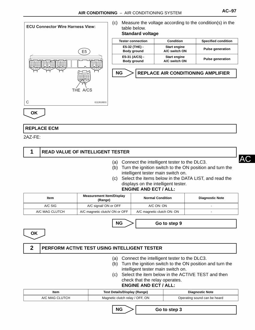
A(c) Measure the voltage according to the condition(s) in the table below.Standard voltage
NG
OK
2AZ-FE:
(a) Connect the intelligent tester to the DLC3.(b) Turn the ignition switch to the ON position and turn the
intelligent tester main switch on.(c) Select the items below in the DATA LIST, and read the
displays on the intelligent tester.ENGINE AND ECT / ALL:
NG
OK
(a) Connect the intelligent tester to the DLC3.(b) Turn the ignition switch to the ON position and turn the
intelligent tester main switch on.(c) Select the item below in the ACTIVE TEST and then
check that the relay operates.ENGINE AND ECT / ALL:
NG
C
THE A/CS
ECU Connector Wire Harness View:
E5
E112610E01
Tester connection Condition Specified condition
E5-32 (THE) - Body ground
Start engine A/C switch ON Pulse generation
E5-31 (A/CS) - Body ground
Start engine A/C switch ON Pulse generation
REPLACE AIR CONDITIONING AMPLIFIER
REPLACE ECM
1 READ VALUE OF INTELLIGENT TESTER
Item Measurement Item/Display (Range) Normal Condition Diagnostic Note
A/C SIG A/C signal/ ON or OFF A/C ON: ON -
A/C MAG CLUTCH A/C magnetic clutch/ ON or OFF A/C magnetic clutch ON: ON -
Go to step 9
2 PERFORM ACTIVE TEST USING INTELLIGENT TESTER
Item Test Details/Display (Range) Diagnostic Note
A/C MAG CLUTCH Magnetic clutch relay / OFF, ON Operating sound can be heard
Go to step 3
AC–98 AIR CONDITIONING – AIR CONDITIONING SYSTEM
AC
OK
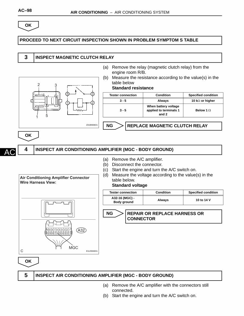
(a) Remove the relay (magnetic clutch relay) from the engine room R/B.
(b) Measure the resistance according to the value(s) in the table belowStandard resistance
NG
OK
(a) Remove the A/C amplifier.(b) Disconnect the connector.(c) Start the engine and turn the A/C switch on.(d) Measure the voltage according to the value(s) in the
table below.Standard voltage
NG
OK
(a) Remove the A/C amplifier with the connectors still connected.
(b) Start the engine and turn the A/C switch on.
PROCEED TO NEXT CIRCUIT INSPECTION SHOWN IN PROBLEM SYMPTOM S TABLE
3 INSPECT MAGNETIC CLUTCH RELAY
1
2 3
5
1 2
35
Z018060E01
Tester connection Condition Specified condition
3 - 5 Always 10 kΩ or higher
3 - 5When battery voltage applied to terminals 1
and 2Below 1 Ω
REPLACE MAGNETIC CLUTCH RELAY
4 INSPECT AIR CONDITIONING AMPLIFIER (MGC - BODY GROUND)
C
A32
Air Conditioning Amplifier Connector Wire Harness View:
MGCE112555E01
Tester connection Condition Specified condition
A32-16 (MGC) - Body ground Always 10 to 14 V
REPAIR OR REPLACE HARNESS OR CONNECTOR
5 INSPECT AIR CONDITIONING AMPLIFIER (MGC - BODY GROUND)

AIR CONDITIONING – AIR CONDITIONING SYSTEM AC–99
C
A(c) Measure the voltage according to the value(s) in the table below.Standard voltage
NG
OK
(a) Disconnect the connector from the magnetic clutch assembly.
(b) Connect the positive (+) lead from the battery to terminal 3 and negative (-) lead to body ground, then check that the magnetic clutch assembly is engaged.
NG
OK
C
A32
Air Conditioning Amplifier Connector Wire Harness View:
MGC
E112556E01
Tester connection Condition Specified condition
A32-16 (MGC) - Body ground A/C switch OFF 10 to 14 V
A32-16 (MGC) - Body ground A/C switch ON Below 1 V
Go to step 9
6 INSPECT MAGNETIC CLUTCH ASSEMBLY
Magnetic Clutch Assembly Connector Front View:
A2
E112579E03
REPLACE MAGNETIC CLUTCH ASSEMBLY

AC–100 AIR CONDITIONING – AIR CONDITIONING SYSTEM
AC
(a) Measure the voltage according to the value(s) in the table below.Standard voltage
NG
OK
(a) Disconnect the connector from the A/C amplifier.(b) Measure the voltage according to the value(s) in the
table below.Standard voltage
NG
7 CHECK HARNESS AND CONNECTOR (MAGNET CLUTCH ASSEMBLY - BODY GROUND)
Magnetic Clutch Assembly Connector Wire Harness View:
A2
E112585E01
Tester connection Condition Specified condition
A32-16 (MGC) - A2-3 A/C switch ON 10 to 14 V
REPAIR OR REPLACE HARNESS OR CONNECTOR
8 CHECK HARNESS AND CONNECTOR (AIR CONDITIONING AMPLIFIER - MAGNET CLUTCH ASSEMBLY)
C
Air Conditioning Amplifier Connector Wire Harness View:
A32
A2
MGC
Magnetic Clutch Assembly Connector Wire Harness View:
E112557E01
Tester connection Condition Specified condition
A32-16 (MGC) - A2-3 A/C switch ON 10 to 14 V
REPAIR OR REPLACE HARNESS OR CONNECTOR

AIR CONDITIONING – AIR CONDITIONING SYSTEM AC–101
C
AOK
(a) Disconnect the connector from the ECU.(b) Measure the resistance according to the value(s) in the
table below.Standard resistance
NG
OK
(a) Remove the ECM with the connectors still connected.(b) Start the engine and turn the A/C switch on.
9 CHECK HARNESS AND CONNECTOR (ECM - AIR CONDITIONING AMPLIFIER)
C
ECM Connector Wire Harness View:
E5
ACT AC1
Air Conditioning Amplifier Connecter Wire Harness View:
A32
ACT AC1
E112611E01
Tester connection Condition Specified condition
E5-24 (AC1) - A32-13 (AC1) Always Below 1.0 Ω
A32-17 (ACT) - E5-25 (ACT) Always Below 1.0 Ω
REPAIR OR REPLACE HARNESS OR CONNECTOR
10 INSPECT AIR CONDITIONING AMPLIFIER
AC–102 AIR CONDITIONING – AIR CONDITIONING SYSTEM
AC
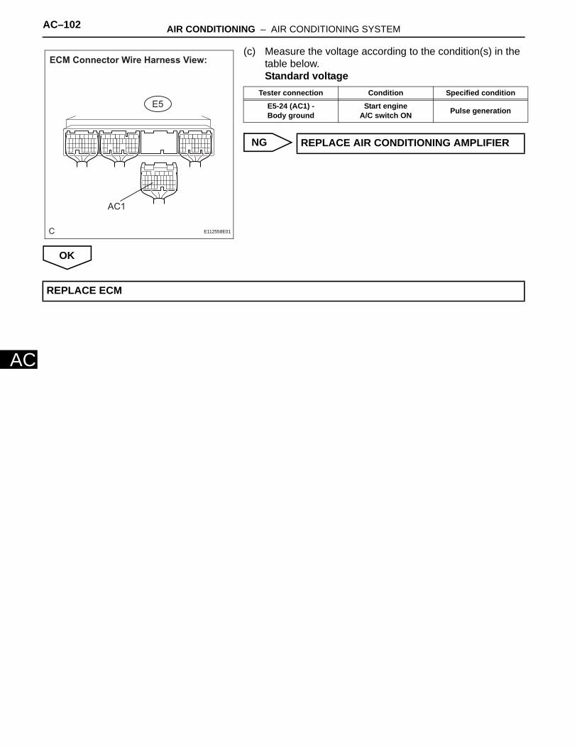
(c) Measure the voltage according to the condition(s) in the table below.Standard voltage
NG
OK
C
AC1
ECM Connector Wire Harness View:
E5
E112558E01
Tester connection Condition Specified condition
E5-24 (AC1) - Body ground
Start engine A/C switch ON Pulse generation
REPLACE AIR CONDITIONING AMPLIFIER
REPLACE ECM

AIR CONDITIONING – AIR CONDITIONING SYSTEM AC–103
C
ADESCRIPTIONThe heater relay is turned on by signals from the A/C amplifier. It supplies power to the blower motor controller.
WIRING DIAGRAM
(a) Remove the HTR fuse from the driver side J/B.(b) Measure the resistance according to the value(s) in the
table below.Standard resiststance
NG
OK
Heater Relay Circuit
1 CHECK FUSE (HTR)
C
A/C Amplifier (A/C Control Assembly)
A11A32(*1)(*2)
1
1
1
1
1
111
1A 1F
2D
HTR (50A) 11
12HTR (10A)From IG1 Relay
ECBattery
HTR Relay
1 2
5 34
Engine Room R/B
IG6
IG2 II1
15 322
2 1
*1: 3MZ-FE *2: 2AZ-FE
Driver Side J/B
HR
Engine Room R/B
Engine Room J/B
ALT
FL MAIN
1
12
2To Blower Motor Controller
E112602E01
Tester item Condition Specified condition
HTR fuse (10 A) Always Below 1 Ω
CHECK FOR SHORT IN ALL HARNESS AND COMPONENTS CONNECTED FAILURE FUSE
AC–104 AIR CONDITIONING – AIR CONDITIONING SYSTEM
AC
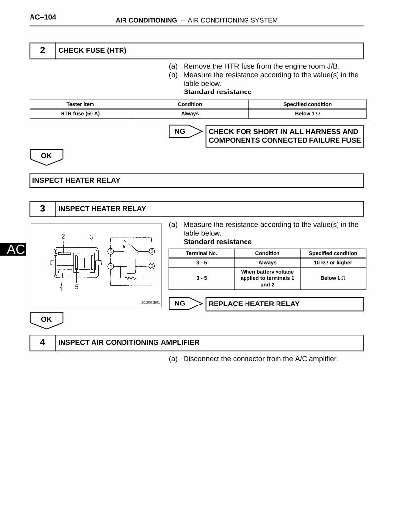
(a) Remove the HTR fuse from the engine room J/B.(b) Measure the resistance according to the value(s) in the
table below.Standard resistance
NG
OK
(a) Measure the resistance according to the value(s) in the table below.Standard resistance
NG
OK
(a) Disconnect the connector from the A/C amplifier.
2 CHECK FUSE (HTR)
Tester item Condition Specified condition
HTR fuse (50 A) Always Below 1 Ω
CHECK FOR SHORT IN ALL HARNESS AND COMPONENTS CONNECTED FAILURE FUSE
INSPECT HEATER RELAY
3 INSPECT HEATER RELAY
1
2 3
5
1 2
35
Z018060E01
Terminal No. Condition Specified condition
3 - 5 Always 10 kΩ or higher
3 - 5When battery voltage applied to terminals 1
and 2Below 1 Ω
REPLACE HEATER RELAY
4 INSPECT AIR CONDITIONING AMPLIFIER

AIR CONDITIONING – AIR CONDITIONING SYSTEM AC–105
C
A(b) Measure the voltage according to the value(s) in the table below.Standard voltage
*1: 3MZ-FE*2: 2AZ-FE
NG
OK
(a) Remove the A/C amplifier with the connectors still connected.
C
Air Conditioning Amplifier Connector Wire Harness View:
3MZ-FE: A11
A322AZ-FE:
HR
HRE112552E08
Tester connection Condition Specified condition
A11-32 (HR)*1, A32-15 (HR)*2-
Body ground
Ignition switchOFF → ON Below 1 V → 10 to 14 V
REPAIR OR REPLACE HARNESS OR CONNECTOR
5 CHECK HARNESS AND CONNECTOR (A/C AMPLIFIER - BATTERY)

AC–106 AIR CONDITIONING – AIR CONDITIONING SYSTEM
AC
(b) Measure the voltage according to the value(s) in the table below.Standard voltage
*1: 3MZ-FE*2: 2AZ-FE
NG
OK
C
Air Conditioning Amplifier Connecter Wire Harness View:
A32
HR
HR
A113MZ-FE:
2AZ-FE:
E112583E02
Tester connection Condition Standard
A11-32 (HR)*1, A32-15 (HR)*2 -
Body ground
Ignition switch position: OFF
Blower switch position: OFF
Below 1 V
A11-32 (HR)*1, A32-15 (HR)*2 -
Body ground
Ignition switch position: ON
Blower switch position: ON
Below 1 V
A11-32 (HR)*1, A32-15 (HR)*2 -
Body ground
Ignition switch position: ON
Blower switch position: OFF
10 to 14 V
REPLACE AIR CONDITIONING AMPLIFIER
PROCEED TO NEXT CIRCUIT INSPECTION SHOWN IN PROBLEM SYMPTOMS TABLE
AIR CONDITIONING – AIR CONDITIONING SYSTEM AC–107
C
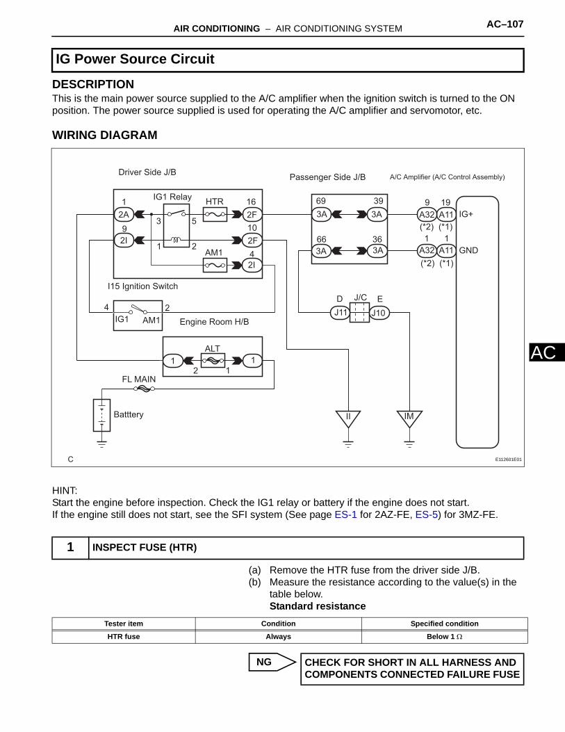
ADESCRIPTIONThis is the main power source supplied to the A/C amplifier when the ignition switch is turned to the ON position. The power source supplied is used for operating the A/C amplifier and servomotor, etc.
WIRING DIAGRAM
HINT:Start the engine before inspection. Check the IG1 relay or battery if the engine does not start.If the engine still does not start, see the SFI system (See page ES-1 for 2AZ-FE, ES-5) for 3MZ-FE.
(a) Remove the HTR fuse from the driver side J/B.(b) Measure the resistance according to the value(s) in the
table below.Standard resistance
NG
IG Power Source Circuit
1 INSPECT FUSE (HTR)
C
A/C Amplifier (A/C Control Assembly)Passenger Side J/BDriver Side J/B
A11A32
A11A32
(*1)(*2)
(*1)(*2)
9 19
1 1
IG+
GND
3A
3A3A
3A69 39
3666
2A
2I
2F
2F
2I
HTR
AM1
IG1 Relay
I15 Ignition Switch
AM1IG124
Engine Room H/B
ALT1 1
FL MAIN
Batttery II IM
J11 J10
J/C
1
9 10
4
16
D E
12
21
3 5
E112601E01
Tester item Condition Specified condition
HTR fuse Always Below 1 Ω
CHECK FOR SHORT IN ALL HARNESS AND COMPONENTS CONNECTED FAILURE FUSE

AC–108 AIR CONDITIONING – AIR CONDITIONING SYSTEM
AC
OK
(a) Remove the A/C amplifier assembly with the connectors still connected.
(b) Turn the ignition switch to the ON position.(c) Measure the voltage according to the value(s) in the
table below.Standard voltage
*1: 3MZ-FE*2: 2AZ-FE
NG
OK
(a) Disconnect the connector from the A/C amplifier.
2 INSPECT AIR CONDITIONING AMPLIFIER (IG+ - BODY GROUND)
C
Air Conditioning Amplifier Connecter Wire Harness View:
A32
IG+
IG+
A113MZ-FE:
2AZ-FE:
E112583E03
Tester connection Condition Specified condition
A11-19 (IG+)*1, A32-9 (IG+)*2-
Body groundIgnition switch ON 10 to 14 V
Go to step 3
PROCEED TO NEXT CIRCUIT INSPECTION SHOWN IN PROBLEM SYMPTOMS TABLE
3 CHECK HARNESS AND CONNECTOR (A/C AMPLIFIER ASSEMBLY - BATTERY)

AIR CONDITIONING – AIR CONDITIONING SYSTEM AC–109
C
A(b) Measure the resistance according to the value(s) in the table below.Standard voltage
*1: 3MZ-FE*2: 2AZ-FE
NG
OK
C
Air Conditioning Amplifier Connector Wire Harness View:
3MZ-FE: A11
A322AZ-FE:
IG+
IG+E112552E01
Tester connection Condition Specified condition
A11-19 (IG+)*1, A32-9 (IG+)*2 -
Body ground
Ignition switch OFF → ON
Below 1.0 V → 10 to 14 V
REPAIR OR REPLACE HARNESS OR CONNECTOR

AC–110 AIR CONDITIONING – AIR CONDITIONING SYSTEM
AC
(a) Measure the resistance according to the value(s) in the table below.Standard resistance
*1: 3MZ-FE*2: 2AZ-FE
NG
OK
4 CHECK HARNESS AND CONNECTOR (A/C AMPLIFIER - BODY GROUND)
C
Air Conditioning Amplifier Connector Wire Harness View:
3MZ-FE: A11
A322AZ-FE:
GND
GND
E112552E04
Tester connection Condition Specified condition
A11-1 (GND)*1, A32-1 (GND)*2 -
Body groundAlways Below 1 Ω
REPAIR OR REPLACE HARNESS OR CONNECTOR
REPLACE AIR CONDITIONING AMPLIFIER

AIR CONDITIONING – AIR CONDITIONING SYSTEM AC–111
C
ADESCRIPTIONThis is the back-up power source circuit for the A/C amplifier. Power is supplied even when turning the ignition switch off and is used for diagnostic trouble code memory, etc.
WIRING DIAGRAM
(a) Turn the ignition switch to the ON position.(b) Set the time displayed on the clock assembly to any time
but 0:00.(c) Turn the ignition switch OFF.(d) Turn the ignition switch to the ON position.(e) Confirm that the time displayed on the clock assembly
shows any time but 0:00.OK:
Time displayed on the clock assembly is any time but 0:00
HINT:The A/C amplifier and clock assembly use the D.C.C fuse for backup power source. If the D.C.C fuse fails, clock assembly backup power source also fails.
Back-up Power Source Circuit
1 INSPECT CLOCK ASSEMBLY
C
A/C Amplifier (A/C Control Assembly)
A11A32
A11A32
10 20(*1)(*2)
(*1)(*2)
1 1B
GND
3A
3A
3A
3A
64 34
66 36
Passenger Side J/BDriver Side J/B
IG5 2I 2G
1D 1A
1 1
Engine Room J/B
Engine Room R/B
D.C.C
7 9
1 2
FL MAIN
Battery
J/C
J11 J10
IM
D E
*1: 3MZ-FE *2: 2AZ-FE
ECU-B3
E112600E01
I036238
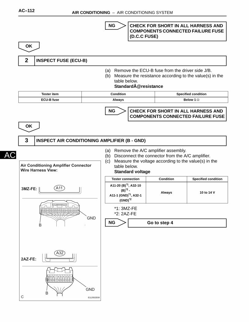
AC–112 AIR CONDITIONING – AIR CONDITIONING SYSTEM
AC
NG
OK
(a) Remove the ECU-B fuse from the driver side J/B.(b) Measure the resistance according to the value(s) in the
table below.StandardÅ@resistance
NG
OK
(a) Remove the A/C amplifier assembly.(b) Disconnect the connector from the A/C amplifier.(c) Measure the voltage according to the value(s) in the
table below.Standard voltage
*1: 3MZ-FE*2: 2AZ-FE
NG
CHECK FOR SHORT IN ALL HARNESS AND COMPONENTS CONNECTED FAILURE FUSE (D.C.C FUSE)
2 INSPECT FUSE (ECU-B)
Tester item Condition Specified condition
ECU-B fuse Always Below 1 Ω
CHECK FOR SHORT IN ALL HARNESS AND COMPONENTS CONNECTED FAILURE FUSE
3 INSPECT AIR CONDITIONING AMPLIFIER (B - GND)
C
Air Conditioning Amplifier Connector Wire Harness View:
3MZ-FE: A11
A322AZ-FE:
GND
GND
B
BE112552E09
Tester connection Condition Specified condition
A11-20 (B)*1, A32-10 (B)*2 -
A11-1 (GND)*1, A32-1 (GND)*2
Always 10 to 14 V
Go to step 4

AIR CONDITIONING – AIR CONDITIONING SYSTEM AC–113
C
AOK
(a) Measure the resistance according to the value(s) in the table below.Standard resistance
*1: 3MZ-FE*2: 2AZ-FE
NG
OK
PROCEED TO NEXT CIRCUIT INSPECTION SHOWN IN PROBLEM SYMPTOMS TABLE
4 CHECK HARNESS AND CONNECTOR (A/C AMPLIFIER - BODY GROUND)
C
Air Conditioning Amplifier Connector Wire Harness View:
3MZ-FE: A11
A322AZ-FE:
GND
GND
E112552E04
Tester connection Condition Specified condition
A11-1 (GND)*1, A32-1 (GND)*2 -
Body groundAlways Below 1 Ω
REPAIR OR REPLACE HARNESS OR CONNECTOR
REPAIR OR REPLACE HARNESS OR CONNECTOR (D.C.C FUSE - A/C AMPLIFIER)

AIR CONDITIONING – AIR CONDITIONING SYSTEM AC–15
C
AThe circle size ( ) indicates the proportion of flow volume.
ACTUATOR CHECK1. ACTUATOR CHECK
(a) Turn the ignition switch to the ON position while pressing the A/C control AUTO switch and R/F (Recirculation / Fresh) switch simultaneously.
(b) As each damper, motor and relay automatically operate the actuator check at 1 second intervals from step No.1 to No.10 continuously, check the temperature and air flow visually and by hand.If a slower display is desired, press the d temperature up switch and change the display in the step operation. Each time the temperature up switch is pressed, the display changes by 1 step. HINT:• Codes are displayed from the smaller to the
larger numbers in order.• To cancel the check mode, press the "OFF"
switch
I036200E01
Step No. Display code Condition
Blower level Air Flow vent Air inlet damper Magnetic clutch Air mix damper
1 0 0 FACE FRESH OFF "COOL" side (Fully close)
2 1 1 FACE FRESH OFF "COOL" side (Fully close)
3 2 14 FACE FRESH ON "COOL" side (Fully close)
4 3 14 FACE RECIRCULATION / FRESH
ON "COOL" side (Fully close)
5 4 14 FACE RECIRCULATION ON "COOL" / "HOT"(50% opened)
6 5 14 B / L RECIRCULATION ON "COOL" / "HOT"(50% opened)
7 6 14 FOOT (MANUAL) RECIRCULATION ON "HOT" side (Fully opened)
8 7 14 FOOT (AUTO) RECIRCULATION ON "HOT" side (Fully opened)
9 8 14 FOOT / DEF RECIRCULATION ON "HOT" side (Fully opened)
10 9 31 DEF RECIRCULATION ON "HOT" side (Fully opened)
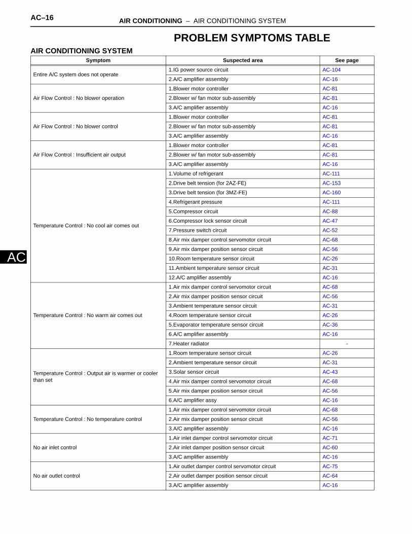
AC–16 AIR CONDITIONING – AIR CONDITIONING SYSTEM
AC
PROBLEM SYMPTOMS TABLEAIR CONDITIONING SYSTEM
Symptom Suspected area See page
Entire A/C system does not operate1.IG power source circuit AC-104
2.A/C amplifier assembly AC-16
Air Flow Control : No blower operation
1.Blower motor controller AC-81
2.Blower w/ fan motor sub-assembly AC-81
3.A/C amplifier assembly AC-16
Air Flow Control : No blower control
1.Blower motor controller AC-81
2.Blower w/ fan motor sub-assembly AC-81
3.A/C amplifier assembly AC-16
Air Flow Control : Insufficient air output
1.Blower motor controller AC-81
2.Blower w/ fan motor sub-assembly AC-81
3.A/C amplifier assembly AC-16
Temperature Control : No cool air comes out
1.Volume of refrigerant AC-111
2.Drive belt tension (for 2AZ-FE) AC-153
3.Drive belt tension (for 3MZ-FE) AC-160
4.Refrigerant pressure AC-111
5.Compressor circuit AC-88
6.Compressor lock sensor circuit AC-47
7.Pressure switch circuit AC-52
8.Air mix damper control servomotor circuit AC-68
9.Air mix damper position sensor circuit AC-56
10.Room temperature sensor circuit AC-26
11.Ambient temperature sensor circuit AC-31
12.A/C amplifier assembly AC-16
Temperature Control : No warm air comes out
1.Air mix damper control servomotor circuit AC-68
2.Air mix damper position sensor circuit AC-56
3.Ambient temperature sensor circuit AC-31
4.Room temperature sensor circuit AC-26
5.Evaporator temperature sensor circuit AC-36
6.A/C amplifier assembly AC-16
7.Heater radiator -
Temperature Control : Output air is warmer or cooler than set
1.Room temperature sensor circuit AC-26
2.Ambient temperature sensor circuit AC-31
3.Solar sensor circuit AC-43
4.Air mix damper control servomotor circuit AC-68
5.Air mix damper position sensor circuit AC-56
6.A/C amplifier assy AC-16
Temperature Control : No temperature control
1.Air mix damper control servomotor circuit AC-68
2.Air mix damper position sensor circuit AC-56
3.A/C amplifier assembly AC-16
No air inlet control
1.Air inlet damper control servomotor circuit AC-71
2.Air inlet damper position sensor circuit AC-60
3.A/C amplifier assembly AC-16
No air outlet control
1.Air outlet damper control servomotor circuit AC-75
2.Air outlet damper position sensor circuit AC-64
3.A/C amplifier assembly AC-16

AIR CONDITIONING – AIR CONDITIONING SYSTEM AC–17
C
AEngine idle up does not occur, or is continuous
1.Compressor circuit AC-88
2.Compressor lock sensor circuit AC-47
3.A/C amplifier assembly AC-16
Displayed set temperature value does not match up with operation of temperature control switch
1.A/C amplifier assembly AC-16
Brightness does not change when rheostat volume or light control switch is adjusted
1.Combination meter (Rheostat) ME-13
2.Illumination circuit -
3.A/C amplifier assembly AC-16
Unable to access the diagnosis mode 1.A/C amplifier assembly AC-16
DTCs are not recorded. Set mode is cleared when IG switch is turned off
1.Back-up power source circuit AC-108
2.A/C amplifier assembly AC-16
Symptom Suspected area See page
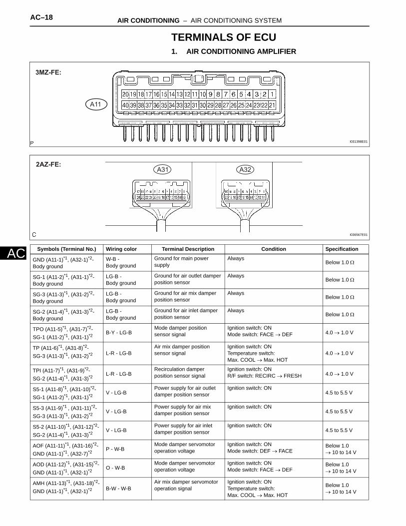
AC–18 AIR CONDITIONING – AIR CONDITIONING SYSTEM
AC
TERMINALS OF ECU1. AIR CONDITIONING AMPLIFIER
A11
3MZ-FE:
I031398E01
Symbols (Terminal No.) Wiring color Terminal Description Condition Specification
GND (A11-1)*1, (A32-1)*2- Body ground
W-B - Body ground
Ground for main powersupply
AlwaysBelow 1.0 Ω
SG-1 (A11-2)*1, (A31-1)*2-Body ground
LG-B - Body ground
Ground for air outlet damperposition sensor
AlwaysBelow 1.0 Ω
SG-3 (A11-3)*1, (A31-2)*2-Body ground
LG-B - Body ground
Ground for air mix damperposition sensor
AlwaysBelow 1.0 Ω
SG-2 (A11-4)*1, (A31-3)*2-Body ground
LG-B - Body ground
Ground for air inlet damperposition sensor
AlwaysBelow 1.0 Ω
TPO (A11-5)*1, (A31-7)*2- SG-1 (A11-2)*1, (A31-1)*2
B-Y - LG-BMode damper position sensor signal
Ignition switch: ONMode switch: FACE → DEF 4.0 → 1.0 V
TP (A11-6)*1, (A31-8)*2- SG-3 (A11-3)*1, (A31-2)*2 L-R - LG-B
Air mix damper position sensor signal
Ignition switch: ONTemperature switch:Max. COOL → Max. HOT
4.0 → 1.0 V
TPI (A11-7)*1, (A31-9)*2- SG-2 (A11-4)*1, (A31-3)*2
L-R - LG-BRecirculation damper position sensor signal
Ignition switch: ONR/F switch: RECIRC → FRESH 4.0 → 1.0 V
S5-1 (A11-8)*1, (A31-10)*2-SG-1 (A11-2)*1, (A31-1)*2
V - LG-BPower supply for air outletdamper position sensor
Ignition switch: ON4.5 to 5.5 V
S5-3 (A11-9)*1 , (A31-11)*2-SG-3 (A11-3)*1, (A31-2)*2
V - LG-BPower supply for air mixdamper position sensor
Ignition switch: ON4.5 to 5.5 V
S5-2 (A11-10)*1, (A31-12)*2-SG-2 (A11-4)*1, (A31-3)*2
V - LG-BPower supply for air inletdamper position sensor
Ignition switch: ON4.5 to 5.5 V
AOF (A11-11)*1, (A31-16)*2- GND (A11-1)*1, (A32-7)*2
P - W-BMode damper servomotor operation voltage
Ignition switch: ONMode switch: DEF → FACE
Below 1.0→ 10 to 14 V
AOD (A11-12)*1, (A31-15)*2- GND (A11-1)*1, (A32-1)*2
O - W-BMode damper servomotor operation voltage
Ignition switch: ONMode switch: FACE → DEF
Below 1.0→ 10 to 14 V
AMH (A11-13)*1, (A31-18)*2-GND (A11-1)*1, (A32-1)*2 B-W - W-B
Air mix damper servomotor operation signal
Ignition switch: ONTemperature switch:Max. COOL → Max. HOT
Below 1.0→ 10 to 14 V
A31 A322AZ-FE:
I036567E01
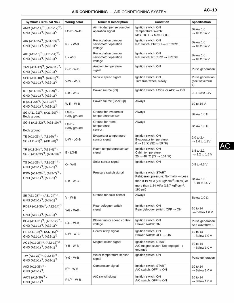
AIR CONDITIONING – AIR CONDITIONING SYSTEM AC–19
C
AAMC (A11-14)*1, (A31-17)*2-GND (A11-1)*1, (A32-1)*2 LG-R - W-B
Air mix damper servomotor operation signal
Ignition switch: ONTemperature switch:Max. HOT → Max. COOL
Below 1.0→ 10 to 14 V
AIR (A11-15)*1, (A31-13)*2- GND (A11-1)*1, (A32-1)*2 R-L - W-B
Recirculation damper servomotor operation voltage
Ignition switch: ONR/F switch: FRESH → RECIRC Below 1.0
→ 10 to 14 V
AIF (A11-16)*1, (A31-14)*2- GND (A11-1)*1, (A32-1)*2 L - W-B
Recirculation damper servomotor operation voltage
Ignition switch: ONR/F switch: RECIRC → FRESH Below 1.0
→ 10 to 14 V
TAM (A11-17)*1, (A32-11)*2- GND (A11-1)*1, (A32-1)*2
G-Y - W-BAmbient temperaturesignal
Ignition switch: ONPulse generation
SPD (A11-18)*1, (A32-2)*2- GND (A11-1)*1, (A32-1)*2 V-W - W-B
Vehicle speed signal Ignition switch: ON Turn front wheel slowly
Pulse generation (see waveform 1)
IG+ (A11-19)*1, (A32-9)*2 - GND (A11-1)*1, (A32-1)*2
L-B - W-BPower source (IG) Ignition switch: LOCK or ACC → ON
0 → 10 to 14V
B (A11-20)*1, (A32-10)*2 - GND (A11-1)*1, (A32-1)*2
W-R - W-BPower source (Back-up) Always
10 to 14 V
SG (A11-21)*1, (A31-20)*2 - Body ground
LG-B - Body ground
Ground for evaporator temperature sensor
AlwaysBelow 1.0 Ω
SG-5 (A11-22)*1, (A31-19)*2 -Body ground
LG-B - Body ground
Ground for room temperaturesensor
AlwaysBelow 1.0 Ω
TE (A11-23)*1, (A31-5)*2 - SG (A11-21)*1, (A31-20)*2 L-W - LG-B
Evaporator temperaturesensor signal
Ignition switch: ONEvaporator temperature:0 → 15 °C (32 → 59 °F)
2.0 to 2.4→ 1.4 to 1.8V
TR (A11-24)*1, (A31-4)*2 - SG-5 (A11-22)*1, (A31-19)*2 B - LG-B
Room temperature sensor signal
Ignition switch: ONCabin temperature:25 → 40 °C (77 → 104 °F)
1.8 to 2.2 → 1.2 to 1.6 V
TS (A11-25)*1, (A31-23)*2 - GND (A11-1)*1, (A32-1)*2
O - W-BSolar sensor signal Ignition switch: ON
0.8 to 4.3 V
PSW (A11-26)*1, (A32-7)*2 - GND (A11-1)*1, (A32-1)*2
L-B - W-B
Pressure switch signal Ignition switch: START Refrigerant pressure: Normally → Less than 0.19 MPa (2.0 kgf/ cm 2, 28 psi) or more than 1.34 MPa (13.7 kgf/ cm 2, 195 psi)
Below 1.0 → 10 to 14 V
S5 (A11-28)*1, (A31-24)*2 - GND (A11-1)*1, (A32-1)*2
V - W-BGround for solar sensor Always
Below 1.0 Ω
RDEF (A11-30)*1, (A32-14)*2 - GND (A11-1)*1, (A32-1)*2
Y-G - W-BRear defogger switchsignal
Ignition switch: ON Rear defogger switch: OFF → ON 10 to 14
→ Below 1.0 V
BLW (A11-31)*1, (A32-12)*2 - GND (A11-1)*1, (A32-1)*2
L-O - W-BBlower motor speed control voltage
Ignition switch: ONBlower switch: ON
Pulse generationSee waveform 1
HR (A11-32)*1, (A32-15)*2 - GND (A11-1)*1, (A32-1)*2
L-W - W-BHeater relay signal Ignition switch: ON
Blower switch: OFF → ON10 to 14→ Below 1.0 V
AC1 (A11-36)*1, (A32-13)*2 - GND (A11-1)*1, (A32-1)*2 Y-B - W-B
Magnet clutch signal Ignition switch: START A/C magnet clutch: Not engaged → engaged
10 to 14 → Below 1.0 V
TW (A11-37)*1, (A32-8)*2 - GND (A11-1)*1, (A32-1)*2
Y-G - W-BWater temperature sensor signal
Ignition switch: ONPulse generation
A/CI (A11-38)*1 - GND (A11-1)*1,
B*1 - W-BCompressor signal Ignition switch: START
A/C switch: OFF → ON10 to 14 → Below 1.0 V
A/CS (A11-39)*1 - GND (A11-1)*1
P-L*1 - W-BA/C switch signal Ignition switch: ON
A/C switch: OFF → ON10 to 14 → Below 1.0 V
Symbols (Terminal No.) Wiring color Terminal Description Condition Specification
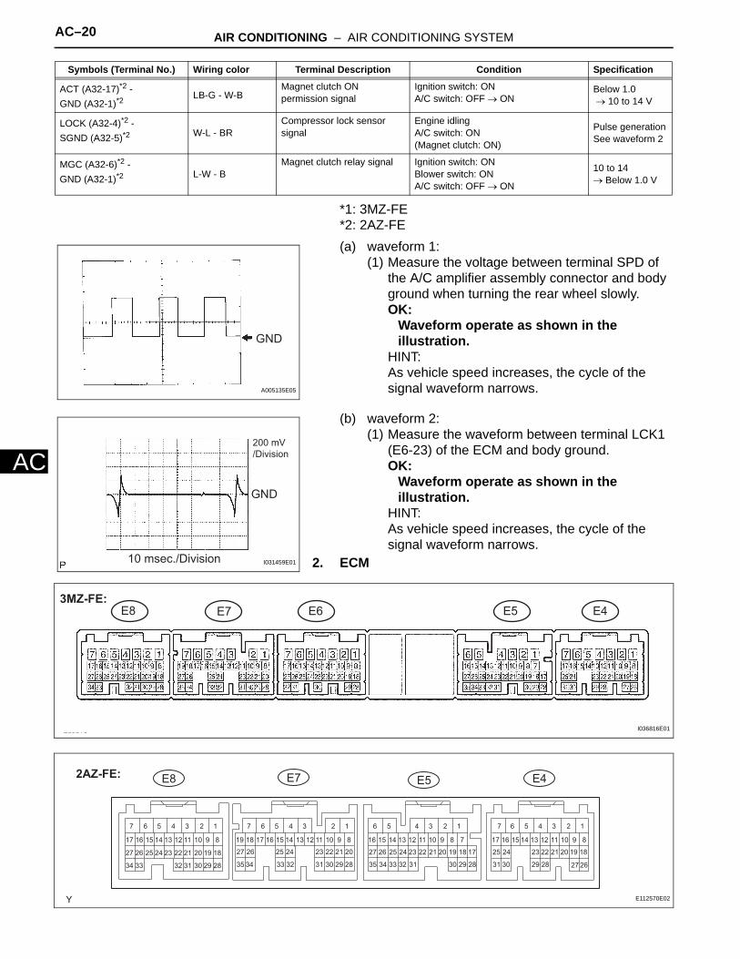
AC–20 AIR CONDITIONING – AIR CONDITIONING SYSTEM
AC
*1: 3MZ-FE*2: 2AZ-FE(a) waveform 1:
(1) Measure the voltage between terminal SPD of the A/C amplifier assembly connector and body ground when turning the rear wheel slowly.OK:
Waveform operate as shown in the illustration.
HINT:As vehicle speed increases, the cycle of the signal waveform narrows.
(b) waveform 2: (1) Measure the waveform between terminal LCK1
(E6-23) of the ECM and body ground.OK:
Waveform operate as shown in the illustration.
HINT:As vehicle speed increases, the cycle of the signal waveform narrows.
2. ECM
ACT (A32-17)*2 - GND (A32-1)*2
LB-G - W-BMagnet clutch ON permission signal
Ignition switch: ONA/C switch: OFF → ON
Below 1.0 → 10 to 14 V
LOCK (A32-4)*2 - SGND (A32-5)*2 W-L - BR
Compressor lock sensor signal
Engine idlingA/C switch: ON(Magnet clutch: ON)
Pulse generationSee waveform 2
MGC (A32-6)*2 - GND (A32-1)*2 L-W - B
Magnet clutch relay signal Ignition switch: ONBlower switch: ONA/C switch: OFF → ON
10 to 14 → Below 1.0 V
Symbols (Terminal No.) Wiring color Terminal Description Condition Specification
GND
A005135E05
GND
200 mV/Division
10 msec./Division I031459E01
E8 E7 E6 E5 E43MZ-FE:
I036816E01
12 1234567 1234 123456 5634567 7
17 16 15 14 13 12 11 10 9 8 17 1716 15 141819 13 12 11 10 9 8 716 15 16 1514 13 12 11 10 9 814 13 12 11 10 98
23 2225 2427 26
27 26
21 20
31 31 3130 29 28 30 3029 28 29 2835 34 35 3433 32 33 3227 26 25 24 23 22 21 20 19 18 27 26 25 24 25 2423 22 21 20 19 18 23 22 21 20 19 1817
34 33 32 31 30 29 28
E8 E5 E4E72AZ-FE:
E112570E02

AIR CONDITIONING – AIR CONDITIONING SYSTEM AC–21
C
A*1: 3MZ-FE*2: 2AZ-FE(a) waveform 1:
(1) Measure the waveform between terminal LCK1 (E6-23) of the ECM and body ground.OK:
Waveform operate as shown in the illustration.
HINT:As vehicle speed increases, the cycle of the signal waveform narrows.
3. CLOCK ASSEMBLY
Symbols (Terminal No.) Wiring color Terminal Description Condition Specification
THW (E8-19)*1, (E8-32)*2 - E2 (E8-28)
(*1) G-B - BR(*2) SB- BR
Water temperature signal Engine idling after engine warmed upCoolant temperature:60 to 120°C (140 to 248°F)
0.2 to 1.0 V
E2 (E8-28)*1, (E8-3)*2 - Body ground
BR - Body ground
Ground for power supply AlwaysBelow 1.0 Ω
E1 (E6-1)*1 - Body ground BR - Body ground
Ground for power supply Always Below 1.0 Ω
LCKI (E6-23)*1 - E1 (E6-1) W-L - BR Compressor lock signal Engine idlingA/C switch: ON (Magnet clutch: ON)
Pulse generation (see waveform 1)
HP (E5-1) - Body Ground (*1) (*1) BR -
Body ground
Pressure switch signal Start engineRefrigerant pressure: Normal → More than 1,520 kPa (15.5 kgf/cm 2, 220psi)
Below 1.0→ 10 to 14 V
ACMG (E5-2)*1 - E1 (E6-1) L-W - BR Compressor operation signal Engine idlingMagnet clutch: OFF → ON
10 to 14→ Below 1.0 V
GND
200 mV/Division
10 msec./Division I031459E01
C5
E071025E01
Symbols (Terminal No.) Wiring color Terminal Description Condition Specification
TH+ (C5-3) - TH- (C5-2) G-R - B-W Ambient temperaturesignal
Ignition switch: ON Ambient temperature: 25°C (77°F) → 40°C (104°F)
1.4 to 1.8 → 0.9 to 1.3 V

AC–22 AIR CONDITIONING – AIR CONDITIONING SYSTEM
AC
DIAGNOSIS SYSTEM1. LIST OF OPERATION METHODS
By operating each of the A/C control switches as shown in the diagram below, it is possible to enter the diagnostic check mode.
Turn the ignition switch to the ON position while pressing the AUTO and R/F switches simultaneously.
Indicator Check (Continuous operation)
DTC Check (Sensor Check) (Continuous operation)
DTC Check (Sensor Check) (Step operation)
Cancel the check mode and start A/C control.
If both AUTO switch and R/F switch are not pressed at the same time.
Actuator Check (Continuous operation)
Actuator Check (Step operation)
AUTO
R/F
DEF
AUTO
AUTO
DEF
DEF
DEF
OFF
OFF
OFF
OFFR/F
R/F
: Indicates a switch operation
R/F: Recirculation/Fresh select switch
DEF: Defogger switch
E112571E01

AIR CONDITIONING – AIR CONDITIONING SYSTEM AC–23
C
A2. CHECK DLC3(a) The vehicle's ECM uses ISO 9141-2 for
communication. The terminal arrangement of the DLC3 complies with SAEJ1962 and matches the ISO 9141-2 format.
DTC CHECK / CLEAR1. INDICATOR CHECK
(a) Turn the ignition switch to the ON position while pressing the A/C control AUTO switch and R/F (Recirculation/Fresh) switch simultaneously.
(b) Check that the indicators come on and go off 4 times in succession at 1 second intervals. HINT:• After the indicator check is completed, the
system enters the DTC mode automatically.• Press the "OFF" switch to cancel the check
mode.2. DTC CHECK (SENSOR CHECK
(a) After the indicator check is completed, the system enters the DTC check mode automatically.
A004550
Terminal No. Connection/Voltage or Resistance Condition
7 Bus + Line/Pulse generation During transmission
4 Chassis Ground - Body Ground/1 Ω or less Always
5 Signal Ground - Body Ground/1 Ω or less Always
16 Battery Positive - Body Ground/9 to 14 V Always
I036200E02
1 Sec. 1 Sec.
ON
OFF
Indication Blinking Pattern:
E112614E02
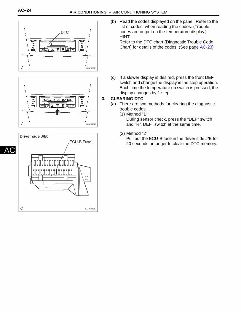
AC–24 AIR CONDITIONING – AIR CONDITIONING SYSTEM
AC
(b) Read the codes displayed on the panel. Refer to the list of codes when reading the codes. (Trouble codes are output on the temperature display.) HINT:Refer to the DTC chart (Diagnostic Trouble Code Chart) for details of the codes. (See page AC-23)
(c) If a slower display is desired, press the front DEF switch and change the display in the step operation. Each time the temperature up switch is pressed, the display changes by 1 step.
3. CLEARING DTC(a) There are two methods for clearing the diagnostic
trouble codes.(1) Method "1"
During sensor check, press the "DEF" switch and "Rr. DEF" switch at the same time.
(2) Method "2" Pull out the ECU-B fuse in the driver side J/B for 20 seconds or longer to clear the DTC memory.
DTC
I036202E01
I036200E05
C
Driver side J/B:ECU-B Fuse
E112572E01

AIR CONDITIONING – AIR CONDITIONING SYSTEM AC–25
C
ADATA LIST / ACTIVE TEST1. DATA LIST
HINT:From the DATA LIST displayed on the intelligent tester, you can read the values of the displays, sensors, actuators and so on without parts removal. Reading the DATA LIST as the first step of troubleshooting is one way to shorten labor time.(a) Connect the intelligent tester to the DLC3.(b) Turn the ignition switch to the ON position.(c) From the display on the tester, select the "DATA
LIST".ENGINE AND ECT / ALL:
2. ACTIVE TESTHINT:Performing the ACTIVE TEST using the intelligent tester allows the relays, VSV, actuators and so on to operate without parts removal. Performing the ACTIVE TEST as the first step of troubleshooting is one way to shorten labor time.It is possible to display the DATA LIST on the intelligent tester during the ACTIVE TEST.(a) Connect the intelligent tester to the DLC3.(b) Turn the ignition switch to the ON position.(c) From the display on the tester, perform the "ACTIVE
TEST".ENGINE AND ECT / ALL:
Item Measurement Item / Display (Range)
Normal Condition Diagnostic Note
A/C SIG A/C signal / ON or OFF A/C ON: ON -
A/C MAG CLUTCH A/C magnet clutch / ON or OFF A/C magnet clutch ON: ON -
Item Test Details / Display (Range) Diagnostic Note
A/C MAG CLUTCH Magnetic clutch relay / OFF, ON Operating sound can be heard

AC–26 AIR CONDITIONING – AIR CONDITIONING SYSTEM
AC
DIAGNOSTIC TROUBLE CODE CHARTIf a malfunction code is displayed during the DTC check (sensor check), check the circuit listed for the code in the table below (proceed to the page given for that circuit).
AIR CONDITIONING SYSTEMDTC No. Detection Item Trouble Area Memory*4 See page
11*1 Room Temperature Sensor Circuit
1. A/C room temperature sensor (cooler (room temp. sensor) thermitor)2. Harness or connector between A/C room temperature sensor (cooler (room temp. sensor) themistor) and A/C and amplifier3. A/C amplifier
Memorized(8.5 min. or moer)
AC-26
12*2 Ambient Temperature Sensor Circuit
1. A/C ambient temperature sensor (cooler (ambient temp. sensor) thermistor2. Harness and connector between A/C ambinet temperature sensor (cooler (ambinet temp. sensor) and clock assembly3. Harness or connector between clock assembly and A/C control assembly4. Clock5. A/C amplifier
Memorized(8.5 min. or more)
AC-31
13 Evaporator Temperature Sensor Circuit
1.A/C evaporator temperature sensor (cooler thermistor No.1)2. Harness or connector between A/C evaporator temperature sensor (cooler thermistor No.1) and A/C amplifier3. A/C amplifier
Memorized(8.5 min. or more)
AC-36
14 Engine Coolant Temperature Communication Circuit
1. Engine coolant temperature sensor2. ECM3. Harness or connector between engine coolant temperature sensor and ECM4. Harness or connector between ECM and amplifier5. A/C amplifier
Memorized(8.5 min. or more)
AC-40
21*3 Solar Sensor Circuit 1. A/C solar sensor (cooler (solar sensor) thermistor)2. Harness or connector between A/C solar sensor (cooler (solar sensor) thermistor) and A/C amplifier3. A/C amplifier
Memorized(8.5 min. or more)*6
-*7
AC-43

AIR CONDITIONING – AIR CONDITIONING SYSTEM AC–27
C
A22*5 Compressor Lock Sensor Circuit
1. A/C lock sensor (cooler compressor assembly)2. Cooler compressor assembly drive belt3. Cooler compressor assembly and magnetic clutch lock sensor4. Harness and connector between ECM and cooler compressor assembly, cooler compressor assembly and body ground5. ECM6. A/C amplifier
- AC-47
23 Pressure Switch Circuit 1. Pressure switch (cooler condenser assembly)2. Harness or connector between pressure switch (cooler condenser assembly) and A/C amplifier, pressur switch (cooler condenser assembly) and body ground3. Refrigerant pipe line4. A/C amplifier
- AC-52
31 Air Mix Damper Position Sensor Circuit (Passenger Side)
1. Air mix control servomotor (air mix damper servo sub-assembly)2. Harness or connector between air mix control servomotor (air mix servo sub-assembly) and A/C amplifierA/C amplifier
Memorized(1 min. or more)
AC-56
32 Air Inlet Damper Position Sensor Circuit
1. Air inlet control servomotor (recirculation damper servo sub-assembly)2. HArness or connector between air inlet control servomotor (recirculation damper servo sub-assembly) and A/C amplifier3. A/C amplifier
Memorized(1 min. or more)
AC-60
33 Air Outlet Damper Position Sensor Circuit
1. Air outlet control servomotor (mode damper servo sub-assembly)2. Harness or connector between air outlet control servomotor (mode damper servo sub-assembly) and A/C amplifier3. A/C amplifier
Memorized(1 min. or more)
AC-64
DTC No. Detection Item Trouble Area Memory*4 See page

AC–28 AIR CONDITIONING – AIR CONDITIONING SYSTEM
AC
HINT:• *1: If the room temperature is approximately -18.6°C (-1.48°F) or lower, DTC 11 may be output even though the system is normal.
• *2: If the ambient temperature is approximately -52.9°C (-63.2°F) or lower, trouble code may be output even though the system is normal.
• *3: If the check is performed in a dark place, DTC 21 (solar sensor circuit abnormal) may be output.
• *4: The A/C amplifier memorizes the DTC of the respective malfunction that has occurred for the period of time indicated in brackets.
• *5: Compressor lock (DTC 22) is indicated only for a current malfunction.To confirm DTC 22, perform the following steps.(a)With the engine on, enter the DTC check mode.(b)Press the R/F switch to enter ctuator check mode and
set the operation to step No.3.(c)Press the AUTO switch to return to DTC check mode.(d)The DTC is displayed after approximately 3 seconds.
• *6: Short• *7: Open
41 Air Mix Damper Control Servomotor Circuit (Passenger Side)
1.Air mix contorl servomotor (air mix damper servo sub-assembly)2, Harness or connector between air mix control servomotor (air mix damper servo sub-assembly) and A/C amplifier3. A/C amplifier
Memorized(15 sec.)
AC-68
42 Air Inlet Damper Control Servomoter Circuit
1. Air inlet control servomotor (recirculation damper servo sub-assembly)2.Harness or connector between air inlet control servmotor (recirculation damper servo sub-assembly) and A/C amplifier3.A/C amplifier
Memorized(15 sec.)
AC-71
43 Air Outlet Damper Control Servomotor Circuit
1. Air outlet control servomotor (mode damper servo sub-assembly)2. Harness or connector between air outlet control servomotor (mode damper servo sub-assembly) and A/C amplifier3. A/C amplifier
Memorized(15 sec.)
AC-75
DTC No. Detection Item Trouble Area Memory*4 See page

AIR CONDITIONING – AIR CONDITIONING SYSTEM AC–29
C
ADESCRIPTIONThis sensor detects the interior temperature that is used as the basis for temperature control and sends appropriate signals to the A/C amplifier.
WIRING DIAGRAM
DTC 11 Room Temperature Sensor Circuit
DTC No. Detection item Trouble Area
11 Open or short in room temperature sensor circuit
• A/C room temperature sensor (cooler (room temp. sensor) thermistor)
• Harness or connector between A/C room temperature sensor (cooler (room temp. sensor) thermistor) and A/C amplifier
• A/C amplifier
C
A/C Amplifier (A/C Contorl Assembly)
TR
SG-5A11
A31
A31
A111
2
A12A/C Room Temperature Sensor (Cooler (Room Temp. Sensor) Thermistor)
*1: 3MZ-FE *2: 2AZ-FE
24
2219
4
(*1)(*2)
(*1)(*2)
E112586E01

AC–30 AIR CONDITIONING – AIR CONDITIONING SYSTEM
AC
(a) Remove the A/C room temperature sensor (cooler (room temp. sensor) thermistor).
(b) Measure the resistance according to the value(s) in the table below.
Standard resistance
1 INSPECT A/C ROOM TEMPERATURE SENSOR (COOLER (ROOM TEMP.SENSOR) THERMISTOR))
A12
A/C Room Temperature Sensor (Cooler (Room Temp. Sensor) Thermistor) Connector front View:
E112573E01
0.0
0.5
1.0
1.5
2.0
2.5
3.0
3.5
4.0
20 40680
0104
60140
(°C)(°F)
Maximum permissible value line
Minimum permissible value line
Resistance (kΩ)
TemperatureI040673E03
Tester connection Condition Specified condition
A12-1 - A12-2 10°C(50°F) 3.00 to 3.73 kΩ
A12-1 - A12-2 15°C(59°F) 2.45 to 2.88 kΩ
A12-1 - A12-2 20°C (68°F) 1.95 to 2.30 kΩ
A12-1 - A12-2 25°C (77°F) 1.60 to 1.80 kΩ
A12-1 - A12-2 30°C (86°F) 1.28 to 1.47 kΩ
A12-1 - A12-2 35°C (95°F) 1.00 to 1.22 kΩ
A12-1 - A12-2 40°C (104°F) 0.80 to 1.00 kΩ
A12-1 - A12-2 45°C (113°F) 0.65 to 0.85 kΩ
A12-1 - A12-2 50°C (122°F) 0.50 to 0.70 kΩ

AIR CONDITIONING – AIR CONDITIONING SYSTEM AC–31
C
ANOTICE:• Even slightly touching the sensor may change the
resistance value. Be sure to hold the connector of the sensor.
• When measuring the sensor temperature must be the same as the ambient temperature.
HINT:As the temperature increases, the resistance decreases (see the graph).
NG
OK
(a) Remove the A/C amplifier with connector still connected.(b) Turn the ignition switch to the ON position.(c) Measure the voltage according to the value(s) in the
table below.Standard voltage
*1: 3MZ-FE*2: 2AZ-FEHINT:As the temperature increases, the voltage decreases.Result:
B
C
A
A12-1 - A12-2 55°C (131°F) 0.44 to 0.60 kΩ
A12-1 - A12-2 60°C (140°F) 0.36 to 0.50 kΩ
REPLACE A/C ROOM TEMPERATURE SENSOR
Tester connection Condition Specified condition
2 INSPECT AIR CONDITIONING AMPLIFIER (TR - SG-5)
C
Air Conditioning Amplifier Connector Wire Harness View:
3MZ-FE: A11
A312AZ-FE:
SG-5 (-)
SG-5 (-)TR (+)
TR (+)
E112546E01
Tester connection Condition Specified condition
A11-24 (TR)*1,A31-4 (TR)*2-A11-22 (SG-5)*1, A31-19 (SG-5)*2
Ignition switch ON at 25°C (77°F)
1.8 to 2.2 V
A11-24 (TR)*1,A31-4 (TR)*2 -A11-22 (SG-5)*1, A31-19 (SG-5)*2
Ignition switch ON at 40°C (104°F)
1.2 to 1.6 V
NG A
OK(Checking from the PROBLEM SYMPTOMS TABLE)
B
OK (Checking from the DTC) C
PROCEED TO NEXT CIRCUIT INSPECTION SHOWN IN PROBLEM SYMPTOMS TABLE
REPLACE AIR CONDITIONING AMPLIFIER
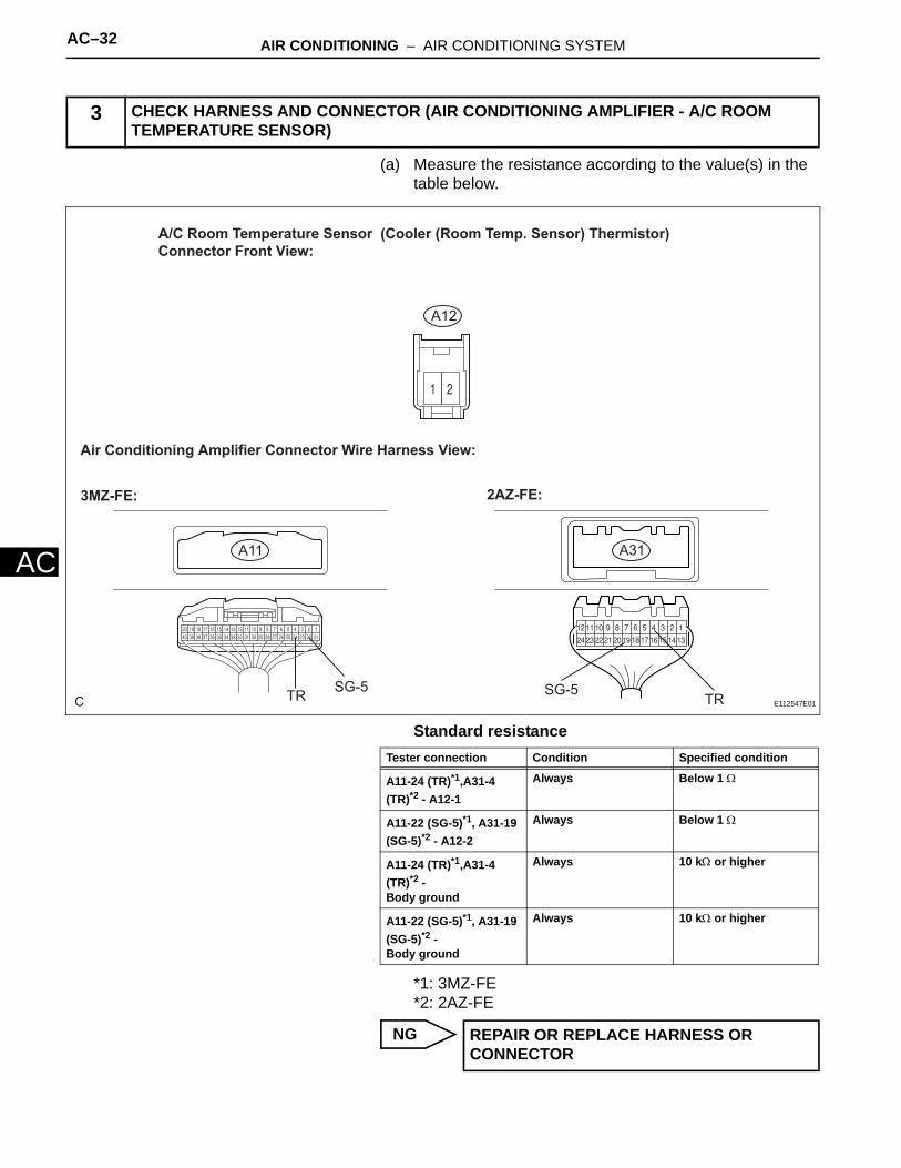
AC–32 AIR CONDITIONING – AIR CONDITIONING SYSTEM
AC
(a) Measure the resistance according to the value(s) in the table below.
Standard resistance
*1: 3MZ-FE*2: 2AZ-FE
NG
3 CHECK HARNESS AND CONNECTOR (AIR CONDITIONING AMPLIFIER - A/C ROOM TEMPERATURE SENSOR)
C
A/C Room Temperature Sensor (Cooler (Room Temp. Sensor) Thermistor) Connector Front View:
A12
A31A11
Air Conditioning Amplifier Connector Wire Harness View:
3MZ-FE: 2AZ-FE:
SG-5TR SG-5TR E112547E01
Tester connection Condition Specified condition
A11-24 (TR)*1,A31-4 (TR)*2 - A12-1
Always Below 1 Ω
A11-22 (SG-5)*1, A31-19 (SG-5)*2 - A12-2
Always Below 1 Ω
A11-24 (TR)*1,A31-4 (TR)*2 -Body ground
Always 10 kΩ or higher
A11-22 (SG-5)*1, A31-19 (SG-5)*2 -Body ground
Always 10 kΩ or higher
REPAIR OR REPLACE HARNESS OR CONNECTOR

AIR CONDITIONING – AIR CONDITIONING SYSTEM AC–33
C
AOK
REPLACE AIR CONDITIONING AMPLIFIER
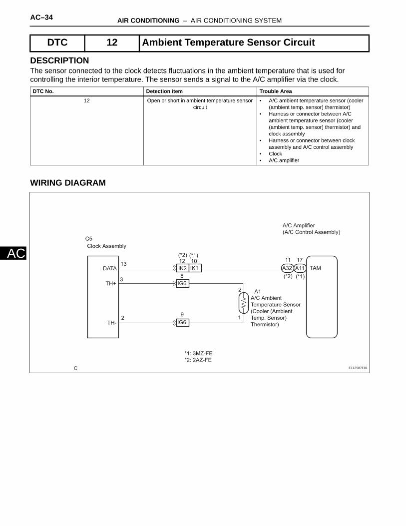
AC–34 AIR CONDITIONING – AIR CONDITIONING SYSTEM
AC
DESCRIPTIONThe sensor connected to the clock detects fluctuations in the ambient temperature that is used for controlling the interior temperature. The sensor sends a signal to the A/C amplifier via the clock.
WIRING DIAGRAM
DTC 12 Ambient Temperature Sensor Circuit
DTC No. Detection item Trouble Area
12 Open or short in ambient temperature sensor circuit
• A/C ambient temperature sensor (cooler (ambient temp. sensor) thermistor)
• Harness or connector between A/C ambient temperature sensor (cooler (ambient temp. sensor) thermistor) and clock assembly
• Harness or connector between clock assembly and A/C control assembly
• Clock• A/C amplifier
C
A/C Amplifier (A/C Control Assembly)
TAMA11A3211 17
IK1IK212 10
IG6
A1A/C Ambient Temperature Sensor (Cooler (Ambient Temp. Sensor) Thermistor)
IG68
9
C5Clock Assembly
DATA
TH+
TH-
13
3
2
*1: 3MZ-FE *2: 2AZ-FE
(*1)(*2)
(*2) (*1)
1
2
E112587E01

AIR CONDITIONING – AIR CONDITIONING SYSTEM AC–35
C
A(a) Check the difference in ambient temperature between the value displayed on the clock assembly and the actual temperature.OK:
The ambient temperature displayed on the clock assembly and the actual ambient temperature are almost the same.
HINT:The temperature displayed on the clock assembly and the actual temperature detected by the sensor may differ when the ambient temperature rises significantly (such as when the vehicle stops immediately after start-up).
OK
NG
(a) Remove the clock assembly with the connector still connected.
(b) Turn the ignition switch to the ON position.(c) Measure the voltage according to the value(s) in the
table below.Standard voltage
HINT:As the temperature increases, the voltage decreases.Result:
B
C
A
1 INSPECT CLOCK ASSEMBLY
I036215
Go to step 5
Go to step 2
2 INSPECT CLOCK ASSEMBLY (TH+ - SG)
C
Clock Assembly Connector Front View:
C5TH+
DATA
TH-
E112574E01
Tester connection Condition Specified condition
C5-3 (TH+) - C5-2 (TH-) Ignition switch ON at 25°C (77°F)
1.8 to 2.2 V
C5-3 (TH+) - C5-2 (TH-) Ignition switch ON at 40°C (104°F)
1.2 to 1.6 V
C5-13 (DATA) - Body ground
Each temperature Pulse generation
NG A
OK(Checking from the PROBLEM SYMPTOMS TABLE)
B
OK (Checking from the DTC) C
PROCEED TO NEXT CIRCUIT INSPECTION SHOWN IN PROBLEM SYMPTOMS TABLE
Go to step 5

AC–36 AIR CONDITIONING – AIR CONDITIONING SYSTEM
AC
(a) Remove the A/C ambient temperature sensor (cooler (ambient temp. sensor) thermistor).
(b) Measure the resistance according to the value(s) in the table below.
Standard resistance
3 INSPECT A/C AMBIENT TEMPERATURE SENSOR (COOLER (AMBIENT TEMP. SENSOR) THERMISTOR)
A1
A/C Ambient Temperature Sensor
(Cooler (Ambient Temp. Sensor)
Thermistor) Connector Front View:
E112575E03
Resistance
Temperature
Maximum permissible value line
Minimum permissible value line
4.0
3.0
3.5
2.5
2.0
1.5
1.0
0.5
00.0
20 40 6032 68 104 140
I040673E02
Tester connection Condition Specified condition
A1-1 - A1-2 10°C (50°F) 3.00 to 3.73 kΩ
A1-1 - A1-2 15°C (59°F) 2.45 to 2.88 kΩ
A1-1 - A1-2 20°C (68°F) 1.95 to 2.30 kΩ
A1-1 - A1-2 25°C (77°F) 1.60 to 1.80 kΩ
A1-1 - A1-2 30°C (86°F) 1.28 to 1.47 kΩ
A1-1 - A1-2 35°C (95°F) 1.00 to 1.22 kΩ
A1-1 - A1-2 40°C (104°F) 0.80 to 1.00 kΩ
A1-1 - A1-2 45°C (113°F) 0.65 to 0.85 kΩ
A1-1 - A1-2 50°C (122°F) 0.50 to 0.70 kΩ

AIR CONDITIONING – AIR CONDITIONING SYSTEM AC–37
C
ANOTICE:• Even slightly touching the sensor may change the
resistance value. Be sure to hold the connector of the sensor.
• When measuring the sensor temperature must be the same as the ambient temperature.
HINT:As the temperature increases, the resistance decreases (see the graph).
NG
OK
(a) Measure the resistance according to the value(s) in the table below.Standard resistance
NG
OK
A1-1 - A1-2 55°C (131°F) 0.44 to 0.60 kΩ
A1-1 - A1-2 60°C (140°F) 0.36 to 0.50 kΩ
REPLACE A/C AMBIENT TEMPERATURE SENSOR
Tester connection Condition Specified condition
4 CHECK HARNESS AND CONNECTOR (CLOCK ASSEMBLY - A/C AMBIENT TEMPERATURE SENSOR)
C5
A1
A/C Ambient Temperature Sensor Cooler (Ambient Temp. Sensor) Thermistor) Connector Wire Harness View:
Clock Assembly Connector Wire Harness View:
TH- TH+
E112576E01
Tester connection Condition Specified condition
C5-3 (TH+) - A1-2 Always Below 1 Ω
C5-2 (TH-) - A1-1 Always Below 1 Ω
C5-3 (TH+) -Body ground
Always 10 kΩ or higher
C5-2 (TH-) -Body ground
Always 10 kΩ or higher
REPAIR OR REPLACE HARNESS OR CONNECTOR
REPLACE CLOCK ASSEMBLY

AC–38 AIR CONDITIONING – AIR CONDITIONING SYSTEM
AC
(a) Measure the resistance according to the value(s) in the table below.
Standard resistance
*1: 3MZ-FE*2: 2AZ-FE
NG
OK
5 CHECK HARNESS AND CONNECTOR (CLOCK ASSEMBLY - A/C CONTROL ASSEMBLY)
C
Clock Assembly Connector Wire Harness View:
A11
C5
A32
Air Conditioning Amplifier Connecter Wire Harness View:
3MZ-FE: 2AZ-FE:
TAM TAM
DATA
E112548E01
Tester connection Condition Specified condition
C5-13 (DATA) - A11-17 (TAM)*1, A32-11 (TAM)*2
Always Below 1 Ω
C5-13 (DATA) - Body ground
Always 10 kΩ or higher
REPAIR OR REPLACE HARNESS OR CONNECTOR
REPLACE AIR CONDITIONING AMPLIFIER
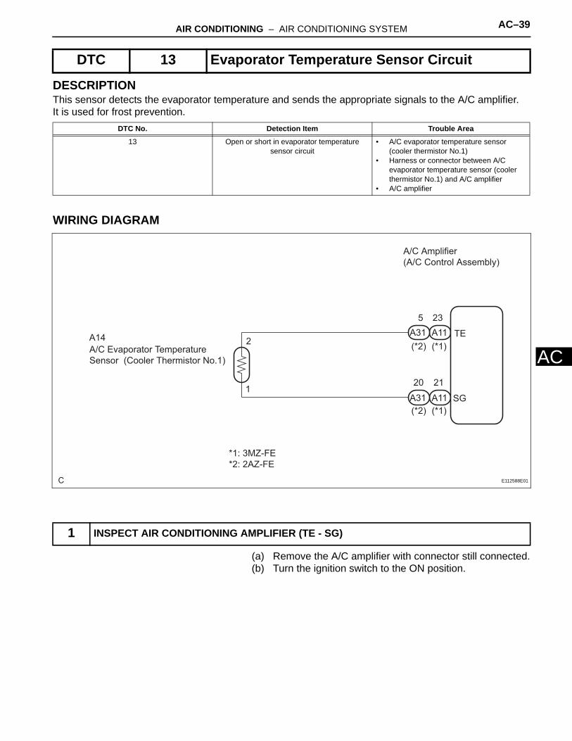
AIR CONDITIONING – AIR CONDITIONING SYSTEM AC–39
C
ADESCRIPTIONThis sensor detects the evaporator temperature and sends the appropriate signals to the A/C amplifier. It is used for frost prevention.
WIRING DIAGRAM
(a) Remove the A/C amplifier with connector still connected.(b) Turn the ignition switch to the ON position.
DTC 13 Evaporator Temperature Sensor Circuit
DTC No. Detection Item Trouble Area
13 Open or short in evaporator temperature sensor circuit
• A/C evaporator temperature sensor (cooler thermistor No.1)
• Harness or connector between A/C evaporator temperature sensor (cooler thermistor No.1) and A/C amplifier
• A/C amplifier
1 INSPECT AIR CONDITIONING AMPLIFIER (TE - SG)
C
A/C Amplifier (A/C Control Assembly)
A11A31
A/C Evaporator Temperature Sensor (Cooler Thermistor No.1)
A14(*1)(*2)
A11A31
5 23
20 21
(*1)(*2)
TE
SG1
2
*1: 3MZ-FE *2: 2AZ-FE
E112588E01

AC–40 AIR CONDITIONING – AIR CONDITIONING SYSTEM
AC
(c) Measure the voltage according to the value(s) in the table below.Standard voltage
*1: 3MZ-FE*2: 2AZ-FEHINT:As the temperature increases, the voltage decreases.Result:
B
C
A
(a) Remove the A/C evaporator temperature sensor (cooler thermistor No.1).
(b) Measure the resistance according to the value(s) in the table below.
C
Air Conditioning Amplifier Connector Wire Harness View:
3MZ-FE: A11
A312AZ-FE:
SG (-)
SG (-)TE (+)
TE (+)
E112546E03
Tester connection Condition Specified condition
A11-23 (TE)*1, A31-5 (TE)*2 - A11-21 (SG)*1, A31-20 (SG)*2
Ignition switch ON at 0°C (32°F)
1.8 to 2.4 V
A11-23 (TE)*1, A31-5 (TE)*2 - A11-21 (SG)*1, A31-20 (SG)*2
Ignition switch ON at 15°C (59°F)
1.4 to 1.8 V
NG A
OK(Checking from the PROBLEM SYMPTOMS TABLE)
B
OK (Checking from the DTC) C
PROCEED TO NEXT CIRCUIT INSPECTION SHOWN IN PROBLEM SYMPTOMS TABLE
REPLACE AIR CONDITIONING AMPLIFIER
2 INSPECT A/C EVAPORATOR TEMPERATURE SENSOR (COOLER THERMISTOR NO.1)
A14
A/C Evaporator Temprature Sensor (Cooler Thermistor No.1) Connector Front View:
E112577E01

AIR CONDITIONING – AIR CONDITIONING SYSTEM AC–41
C
AStandard voltage
NOTICE:• Even slightly touching the sensor may change the
resistance value. Be sure to hold the connector of the sensor.
• When measuring the sensor temperature must be the same as the ambient temperature.
HINT:As the temperature increases, the resistance decrease (see the graph ).
NG
OK
(a) Measure the resistance according to the value(s) in the table below.
0.01.02.03.04.05.06.07.08.09.0
10.011.012.0
-20 0 20 40
-4 32 68 104
(°C)
(°F)
Resistance (kΩ) Maximum permissible value line
Mimimum permissible value line
Temperature
I040629E01
Tester connection Condition Specified condition
A14-1 - A14-2 -10°C (14°F) 8.00 to 10.00 kΩ
A14-1 - A14-2 -5°C (23°F) 6.15 to 7.65 kΩ
A14-1 - A14-2 0°C (32°F) 4.75 to 5.85 kΩ
A14-1 - A14-2 5°C (41°F) 3.70 to 4.55 kΩ
A14-1 - A14-2 10°C (50°F) 2.91 to 3.55 kΩ
A14-1 - A14-2 15°C (59°F) 2.32 to 2.80 kΩ
A14-1 - A14-2 20°C (68°F) 1.85 to 2.22 kΩ
A14-1 - A14-2 25°C (77°F) 1.48 to 1.77 kΩ
A14-1 - A14-2 30°C (86°F) 1.20 to 1.43 kΩ
REPLACE A/C EVAPORATOR TEMPERATURE SENSOR
3 CHECK HARNESS AND CONNECTOR (A/C AMPLIFIER - A/C EVAPORATOR TEMPERATURE SENSOR)

AC–42 AIR CONDITIONING – AIR CONDITIONING SYSTEM
AC
Standard resistance*1: 3MZ-FE*2: 2AZ-FE
NG
OK
C
Air conditioning Amplifier Connector Wire Harness View:
A/C Evaporator Temperature Sensor (Cooler Thermistor Connecter No.1) Connector Wire Harness View:
A14
A11 A31
2AZ-FE:3MZ-FE:
SGTE TE
SG
E112547E02
Tester connection Condition Specified condition
A11-23 (TE)*1, A31-5 (TE)*2- A14-2
Always Below 1 Ω
A11-21 (SG)*1, A31-20 (SG)*2 - A14-1
Always Below 1 Ω
A11-23 (TE)*1, A31-5 (TE)*2 -Body ground
Always 10 kΩ or higher
A11-21 (SG)*1, A31-20 (SG)*2 -Body ground
Always 10 kΩ or higher
REPAIR OR REPLACE HARNESS OR CONNECTOR
REPLACE AIR CONDITIONING AMPLIFIER

AC–116 AIR CONDITIONING – REFRIGERANT
AC
REPLACEMENT1. DISCHARGE REFRIGERANT FROM
REFRIGERATION SYSTEM(a) Start up the engine.(b) A/C switch is ON.(c) Operate the cooler compressor with an engine
speed of approximately 1,000 rpm for 5 to 6 minutes to circulate the refrigerant and collect the compressor oil remaining in each component into the cooler compressor.
(d) Stop the engine.(e) Using SST, discharge the refrigerant gas.
SST 07110-58060 (07117-58080, 07117-58090, 07117-78050, 07117-88060, 07117-88070, 07117-88080)
2. CHARGE REFRIGERANT(a) Perform vacuum purging using a vacuum pump.(b) Charge refrigerant HFC-134a (R134a).
Standard:550 +- 50 g (19.39 +- 1.76 oz.)
SST 07110-58060 (07117-58060, 07117-58070, 07117-58080, 07117-58090, 07117-78050, 07117-88060, 07117-88070, 07117-88080)
NOTICE:Do not operate the cooler compressor before charging refrigerant as the cooler compressor will not work properly without any refrigerant, and will overheat.
3. WARM UP ENGINE(a) Warm up the engine at less than 2,000 rpm for 2
minutes or more after charging the refrigerant.
Amount to be charged Mean value in proper range
Overcharged
Refrigerant AmountSub-cool system
High Pressure
+- 50 g (+- 1.76 oz.)
I040570E03

AIR CONDITIONING – REFRIGERANT AC–117
C
A4. CHECK FOR LEAKAGE OF REFRIGERANT(a) After recharging the refrigerant gas, check for
refrigerant gas leakage using a halogen leak detector.
(b) Perform the operation under these conditions:• Stop the engine.• Secure good ventilation (the gas leak detector
may react to volatile gases other than refrigerant, such as evaporated gasoline or exhaust gas).
• Repeat the test 2 or 3 times. • Make sure that some refrigerant remains in the
refrigeration system. When compressor is off: approximately 392 to 588 kPa (4 to 6 kgf*cm2, 57 to 85 psi)
(c) Bring the gas leak detector close to the drain hose before performing the test.HINT:• After the blower motor has stopped, leave the
cooling unit for more than 15 minutes.• Expose the gas leak detector sensor under the
drain hose.• When bringing the gas leak detector close to the
drain hose, make sure that the gas leak detector does not react to the volatile gases.
If such reaction is unavoidable, the vehicle must be lifted up.
(d) If a gas leak is not detected on the drain hose, remove the blower motor control (blower resistor) from the cooling unit. Insert the gas leak detector sensor into the unit and perform the test.
(e) Disconnect the connector and leave the pressure switch on for approximately 20 minutes. Bring the gas leak detector close to the pressure switch and perform the test.
(f) Bring the gas leak detector close to the refrigerant lines and perform the test.
Drain Hose
Gas Leak Detector
N014519E01

AIR CONDITIONING – REFRIGERANT AC–111
C
AREFRIGERANTON-VEHICLE INSPECTION1. INSPECT REFRIGERANT PRESSURE WITH
MANIFOLD GAUGE SET(a) This method uses a manifold gauge set to locate
problem areas. Read the manifold gauge pressure when these conditions are established. Test conditions:• Temperature at the air inlet is 30 to 35°C (86 to
95°F).• Engine is running at 1,500 rpm.• All doors are fully open.• Blower speed control switch is at HI.• Temperature control switch is at MAX. COOL.• A/C switch is ON.
(b) Gauge readings (Reference)
Pressure on low-pressure side MPa (kgf/cm2)
0.5 (5.0)
0.5 (5.0)
0.4 (4.0)
0.3 (3.0)
0.2 (2.0)
1.0 (10.0) 1.5 (15.0) 2.0 (20.0)
Blower HI Zone
1.06 (10.80)
1.2 (12.23)
1.25 (12.74)
1.32 (13.46)
0.27 (2.75)
0.22 (2.24)0.2 (2.03)
0.14 (1.42)
Blower LO Zone
Pressure on high-pressure side MPa (kgf/cm2)
I030081E04

AC–112 AIR CONDITIONING – REFRIGERANT
AC
(1) Normally functioning refrigeration systemGauge reading
(2) The A/C system periodically changes between normal and improper function due to moisture in the refrigerant system.
(3) The A/C system does not function effectively due to insufficient cooling.
E050573E01
Pressure side Refrigerant volume
Low 0.15 to 0.25 MPa (1.5 to 2.5 kgf/cm2)
High 1.37 to 1.57 MPa (14 to 16 kgf/cm2)
Symptoms Probable Cause Diagnosis Corrective Actions
During operation, pressure on low - pressure side cycles between normal and vacuum
Moisture in refrigeration system freezes at expansion valve orifice, causing temporary stop of cycle. However, when melted, normal state is restored
- Drier is overly saturated- Moisture in refrigeration system freezes at expansion valve orifice and blocks refrigerant circulation
1. Replace cooler drier2. Remove moisture from cycle by repeatedly evacuating air 3. Supply appropriate volume of new refrigerant
I022117
Symptoms Probable Cause Diagnosis Corrective Actions
- Pressure low on both low and high-pressure sides- Cooling performance insufficient
Gas leakage from refrigeration system
- Insufficient refrigerant- Refrigerant leakage
1. Check for gas leakage and repair if necessary2. Supply appropriate volume of new refrigerant3. If indicated pressure value close to 0 when connected to gauge, create vacuum after inspecting and repairing the location of leakage
I022118

AIR CONDITIONING – REFRIGERANT AC–113
C
A(4) The A/C system does not function effectively due to poor circulation of the refrigerant.
(5) The A/C system does not function intermittently because the refrigerant does not circulate.
(6) The A/C system does not function effectively due to overcharged refrigerant or insufficient cooling of the condenser.
Symptoms Probable Cause Diagnosis Corrective Actions
- Pressure low on both low and high-pressure sides- Frost exists on piping from condenser to A/C unit
Refrigerant flow obstructed by dirt in condenser
Condenser clogged Replace condenser
I022119
Symptoms Probable Cause Diagnosis Corrective Actions
- Vacuum indicated on low-pressure side, and extremely low pressure indicated on high-pressure side - Frost or condensation seen on piping on both sides of condenser or expansion valve
- Refrigerant flow obstructed by moisture or dirt in refrigeration system- Refrigerant flow obstructed by gas leakage from expansion valve
Refrigerant does not circulate 1. Check expansion valve 2. Clean expansion valve by blowing air3. Replace condenser 4. Evacuate air and charge appropriate volume of new refrigerant5. For gas leakage from expansion valve, replace expansion valve
I022120
I022121

AC–114 AIR CONDITIONING – REFRIGERANT
AC
(7) The A/C system does not function due to air in the refrigeration system.CAUTION:The low-pressure piping may be very hot and cause serious burns.
(8) The A/C system does not function effectively due to an expansion valve malfunction.
Symptoms Probable Cause Diagnosis Corrective Actions
Pressure extremely high on both low and high-pressure sides
- Excessive refrigerant- Cooling performance of condenser insufficient
- Condenser is dirty- Condenser fan motor is malfunctioning- Excessive refrigerant
1. Clean condenser2. Check condenser fan motor operation3. If 1 and 2 normal, check the amount of refrigerant and supply appropriate volume of refrigerant
Symptoms Probable Cause Diagnosis Corrective Actions
- Pressure extremely high on both low and high-pressure sides - The low-pressure piping is too hot to touch
Air in refrigeration system - Air in refrigeration system- Vacuum purging insufficient
1. Check if compressor oil is dirty or insufficient2. Evacuate air and charge new refrigerant
HINT: These gauge indications occur when the refrigeration system opens and the refriger-ant is charged without vacuum purging
I022122E03
Symptoms Probable Cause Diagnosis Corrective Actions
-Pressure extremely high on both low and high-pressure sides -Frost or condensation on piping on low-pressure side
Problem with expansion valve - Excessive refrigerant in low pressure piping- Expansion valve too wide open
Replace expansion valve
I022123

AIR CONDITIONING – REFRIGERANT AC–115
C
A(9) The A/C system does not function due to a defective compressor.
Symptoms Probable Cause Diagnosis Corrective Actions
-Pressure extremely high on both low and high-pressure sides -Pressure extremely low on high-pressure side
Internal leakage in compressor - Compression failure- Leakage from damaged valve or broken sliding parts
Repair or replace compressor
I022124

AC–118 AIR CONDITIONING – REFRIGERANT LINE
AC
HEATER & AIR CONDITIONING SYSTEMAIR CONDITIONINGREFRIGERANT LINECOMPONENTS
COOLAER REFRIGERANT LIQUID PIPE A
PIPING CLAMP (QUICK JOINT)COOLER REFRIGERANT SUCTION HOSE NO.1
2AZ-FE:
COOLER CONDENSER ASSEMBLY
COOLER REFRIGERANT DISCHARGE HOSE NO.1
COOLER COMPRESSOR ASSEMBLY
9.8 (100, 87 in.*lbf)
5.4 (55, 49 in.*lbf)
9.8 (100, 87 in.*lbf)
N*m (kgf*cm, ft.*lbf) : Specified torque
C109676E01

AIR CONDITIONING – REFRIGERANT LINE AC–119
C
ACOOLAER REFRIGERANT LIQUID PIPE A
PIPING CLAMP (QUICK JOINT)COOLER REFRIGERANT SUCTION HOSE NO.1
3MZ-FE:
COOLER CONDENSER ASSEMBLY
COOLER REFRIGERANT DISCHARGE HOSE NO.1
COOLER COMPRESSOR ASSEMBLY
9.8 (100, 87 in.*lbf)
5.4 (55, 49 in.*lbf)
9.8 (100, 87 in.*lbf)
9.8 (100, 87 in.*lbf)
N*m (kgf*cm, ft.*lbf) : Specified torque
C109677E01

AC–122 AIR CONDITIONING – AIR CONDITIONING UNIT
AC
REMOVALHINT:• Installation is in the reverse order of removal.• COMPONENTS: See page AC-120.
1. DISCHARGE REFRIGERANT FROM REFRIGRATION SYSTEM (See page AC-115)
2. DISCONNECT COOLER REFRIGERANT SUCTION HOSE NO.1(a) Install SST to the piping clamp.
SST 09870-00015HINT:Check the direction of the piping clamp claw and SST by referring to the illustration shown on the caution label.
(b) Push down on the SST and release the clamp lock.NOTICE:Be careful not to deform the hose when pushing down on the SST.
(c) Pull the SST slightly and push the release lever, then remove the piping clamp with the SST.
(d) Disconnect the cooler refrigerant suction hose No.1.NOTICE:• Do not use tools such as a screwdriver to
remove the hose.• Cap the open fittings immediately to keep
moisture or dirt out of the system.(e) Remove the 2 O-rings from the cooler refrigerant
suction hose No.1.NOTICE:Seal the openings of the disconnected parts using vinyl tape to prevent moisture and foreign matter from entering.
3. DISCONNECT COOLER REFRIGERANT LIQUID PIPE ASST 09870-00025HINT:Disconnection of the cooler refrigerant liquid pipe A is the same as the cooler refrigerant suction hose No.1.
Push Pull
SST
Release LeverI003839E01
Disconnect the Tube Using Hand Screw
Driver
I006919E01

AIR CONDITIONING – AIR CONDITIONING UNIT AC–123
C
A4. DISCONNECT HEATER WATER OUTLET HOSE A(FROM HEATER UNIT)(a) Using pliers, grip the claws of the clip and slide the
clip. Disconnect the heater water outlet hose A (from the heater unit).NOTICE:• Do not apply any excessive force to the
heater water outlet hose.• Prepare a drain pan or cloth for when the
cooling water leaks.5. DISCONNECT HEATER WATER INLET HOSE A (for
2AZ-FE)HINT:Disconnection of the heater water inlet hose A is the same as the heater water outlet hose A.
6. DISCONNECT HEATER OUTLET WATER HOSE (for 3MZ-FE)HINT:Disconnection of the heater outlet water hose is the same as the heater water outlet hose A.
7. DISCONNECT HEATER INLET WATER HOSE (for 3MZ-FE)HINT:Disconnection of the heater inlet water hose is the same as the heater water outlet hose A.
8. REMOVE INSTRUMENT PANEL SAFETY PADSee page IP-6HINT:Refer to the instructions for removal of the instrument panel safety pad sub-assembly with passenger air bag assembly.
9. REMOVE AIR DUCT REAR NO.1(a) Fold back the floor carpet.
HINT:Fold back the floor carpet so that the air duct rear No.1 can be removed.
(b) Remove the 2 screws, bolt and nut.(c) Remove the air duct rear No.1.
10. REMOVE AIR DUCT REAR NO.2(a) Fold back the floor carpet.
HINT:Fold back the floor carpet so that the air duct rear No.2 can be removed.
(b) Remove the 2 screws, bolt and nut.(c) Remove the air duct rear No.2.
I031522
I038469
I038470
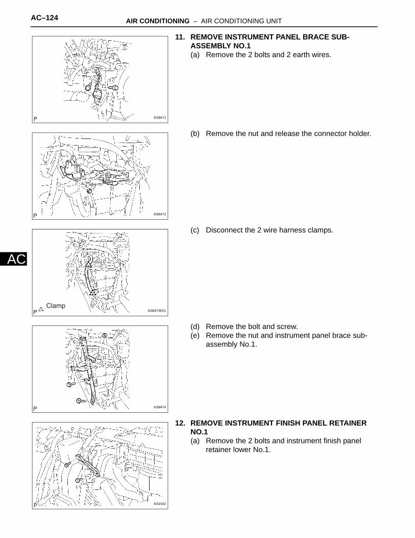
AC–124 AIR CONDITIONING – AIR CONDITIONING UNIT
AC
11. REMOVE INSTRUMENT PANEL BRACE SUB-ASSEMBLY NO.1(a) Remove the 2 bolts and 2 earth wires.
(b) Remove the nut and release the connector holder.
(c) Disconnect the 2 wire harness clamps.
(d) Remove the bolt and screw.(e) Remove the nut and instrument panel brace sub-
assembly No.1.
12. REMOVE INSTRUMENT FINISH PANEL RETAINER NO.1(a) Remove the 2 bolts and instrument finish panel
retainer lower No.1.
I038471
I038472
ClampI038473E01
I038474
I031502
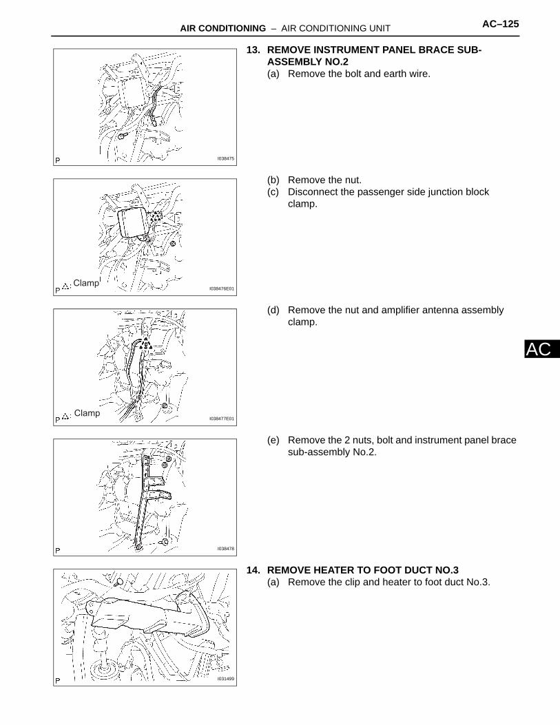
AIR CONDITIONING – AIR CONDITIONING UNIT AC–125
C
A13. REMOVE INSTRUMENT PANEL BRACE SUB-ASSEMBLY NO.2(a) Remove the bolt and earth wire.
(b) Remove the nut.(c) Disconnect the passenger side junction block
clamp.
(d) Remove the nut and amplifier antenna assembly clamp.
(e) Remove the 2 nuts, bolt and instrument panel brace sub-assembly No.2.
14. REMOVE HEATER TO FOOT DUCT NO.3(a) Remove the clip and heater to foot duct No.3.
I038475
ClampI038476E01
ClampI038477E01
I038478
I031499

AC–126 AIR CONDITIONING – AIR CONDITIONING UNIT
AC
15. REMOVE HEATER TO FOOT DUCT NO.1(a) Remove the clip and heater to foot duct No.1.
16. DISCONNECT INSTRUMENT PANEL JUNCTION BLOCK ASSEMBLY(a) Remove the 3 nuts and instrument panel junction
block assembly.
17. REMOVE INSTRUMENT PANEL BRACKET SUB-ASSEMBLY CENTER(a) Remove the nut and instrument panel bracket sub-
assembly center.
18. DISCONNECT STEERING COLUMN ASSEMBLY(a) Release the wire harness clamp and 3 connectors.
(b) Remove the bolt and 2 nuts and disconnect the steering column assembly.
I038479
I038480
I038483
Clamp I039252E01
I038482

AIR CONDITIONING – AIR CONDITIONING UNIT AC–127
C
A19. REMOVE INSTRUMENT PANEL REINFORCEMENT ASSEMBLY(a) Disconnect the 7 wire harness clamps from the
instrument panel reinforcement assembly.
(b) Remove the 3 nuts, and disconnect the 3 earth wires from the instrument panel reinforcement assembly.
ClampI038484E01
I038540

AC–128 AIR CONDITIONING – AIR CONDITIONING UNIT
AC
(c) Remove the 3 caps, 7 bolts and instrument panel reinforcement.
20. REMOVE STEREO COMPONENT AMPLIFIER ASSEMBLYHINT:See page AV-85
21. REMOVE ECMHINT:• 2AZ-FE (See page ES-333)• 3MZ-FE (See page ES-366)
22. REMOVE BLOWER ASSEMBLY(a) Disconnect the connectors.(b) Remove the screw.(c) Disconnect the blower connector holder clamp.
(d) Disconnect the 5 wire harness clamps.
I038541
Clamp I038542E01
Clamp I038543E01

AIR CONDITIONING – AIR CONDITIONING UNIT AC–129
C
A(e) w/ stereo component amplifier assembly:Disconnect the 2 wire harness clamps.
(f) Manual A/C model:Disconnect the 4 connectors and remove the clamp.
(g) Auto A/C model:Disconnect the 3 connectors and remove the clamp.
(h) Remove the 2 screws, 2 nuts and blower assembly.
23. REMOVE DEFROSTER NOZZLE ASSEMBLY LOWER(a) Release the 4 fitting claws and remove the defroster
nozzle assembly lower.
Clamp I038544E01
: Clamp
Manual A/C model:
Auto A/C model:
I038697E01
I038547
Claw I038548E01

AC–130 AIR CONDITIONING – AIR CONDITIONING UNIT
AC
24. REMOVE AIR CONDITIONING RADIATOR ASSEMBLY(a) Remove the drain hose.(b) Disconnect the connectors.(c) Remove the 2 nuts and air conditioning radiator
assembly.
DISASSEMBLY1. REMOVE MODE DAMPER SERVO SUB-ASSEMBLY
(a) Remove the 3 screws and air outlet control servomotor (mode damper servo sub-assembly).
2. REMOVE HEARTER RADIATOR UNIT SUB-ASSEMBLY(a) Remove the screw and plate.(b) Release the 2 fitting claws and remove the piping
clamp.(c) Remove the heater radiator unit sub-assembly.
NOTICE:Prepare a drain pan or cloth for when the cooling water leaks.
3. REMOVE AIRMIX DAMPER SERVO SUB-ASSEMBLY(a) Remove the 3 screws and airmix control servomotor
(airmix damper servo sub-assembly).
4. REMOVE AIR CONDITIONING TUBE ASSEMBLY(a) Remove the packing.
NOTICE:Be careful not to break the packing as it is to be reused.
I040417
I031512
Claw I038549E01
I031514
Packing
I031515E01

AIR CONDITIONING – AIR CONDITIONING UNIT AC–131
C
A(b) Using a hexagon wrench 4 mm (0.16 in.), remove the 2 hexagon bolts and air conditioning tube assembly.
(c) Remove the 2 O-rings from the air conditioning tube assembly.
5. REMOVE COOLER EXPANSION VALVE(a) Remove the cooler expansion valve from the cooler
evaporator sub-assembly No.1.
6. REMOVE COOLER THERMISTOR NO.1(a) Release the 2 fitting claws and remove the
evaporator temperature sensor (cooler thermistor No.1).
7. REMOVE COOLER EVAPORATOR SUB-ASSEMBLY NO.1(a) Remove the 12 screws and heater case LH.
(b) Remove the cooler evaporator sub-assembly No.1 from the heater case RH.
(c) Remove the 2 O-rings from the cooler evaporator sub-assembly No.1.
I031516
I031517
ClawI038981E01
I031519
I031520

AC–132 AIR CONDITIONING – AIR CONDITIONING UNIT
AC
INSPECTION1. INSPECT AIR MIX DAMPER SERVO (AIR MIX
DAMPER SERVO SUB-ASSEMBLY)(MANUAL AIR CONDITIONING)HINT:The air mix control servomotor (air mix damper servo sub-assembly) can be removed following the disassembly procedure for air conditioning radiator assembly (see page AC-130). (a) Inspect servomotor operation.
(1) Connect the positive (+) lead from the battery to terminal 4 and negative (-) lead to terminal 5, then check that the arm turns to the "MAX. COOL" side smoothly.
(2) Connect the positive (+) lead from the battery to terminal 5 and negative (-) lead to terminal 4, then check that the arm turns to the "MAX. HOT" side smoothly.If operations are not as specified, replace the air mix servomotor.
(b) Inspect position sensor resistance.
(1) Measure the resistance between terminals at each servomotor arm position as shown in the chart.Standard resistance
If the resistance is not as specified, replace the servomotor.
2. INSPECT AIR OUTLET CONTROL SERVOMOTOR (MODE DAMPER SERVO SUB-ASSEMBLY)(MANUAL AIR CONDITIONING)HINT:The air outlet control servomotor (mode damper servo sub-assembly) can be removed following the disassembly procedure for air conditioning radiator assembly (see page AC-130).
Connector Front View:
A19
(Air Mix Damper Servo Sub-assembly)
Air Mix Control Servomotor
I030157E01
MAX. HOT
MAX. COOL
I030332E01
MAX. HOTMAX. COOL0.8 to 1.6
3.4 to 6.2Arm position
Resistance (kΩ)
I030161E01
Tester Connection Condition Specified Condition
1 - 2 Constant 4.2 to 6.8 kΩ
1 - 3 Arm position at"MAX. COOL" 3.4 to 6.2 kΩ
1 - 3 Arm position at"MAX. HOT" 0.8 to 1.6 kΩ

AIR CONDITIONING – AIR CONDITIONING UNIT AC–133
C
A(a) Inspect servomotor operation.(1) Connect the positive (+) lead from the battery
to terminal 7 and the negative (-) lead to terminal 8.
(2) Connect the negative (-) lead from the battery to each terminal as shown in the chart, and check that the shaft rotates to each position, as shown in the illustration.
If operation is not as specified, replace the servomotor.
3. INSPECT A/C EVAPORATOR TEMPERATURE SENSOR (COOLER THERMISTOR NO.1)(MANUAL AIR CONDITIONING)HINT:The A/C evaporator temperature sensor (cooler thermistor No.1) can be removed following the disassembly procedure for the air conditioning radiator assembly (see page AC-130). (a) Remove the A/C evaporator temperature sensor
(cooler thermistor No.1).
FOOT
FOOT/DEF FACE
A20
DEF
B\L
Air Outlet Control Servomotor (Mode Damper Servo Sub-assembly) Connector Front View:
I031408E01
Connected terminal Position
1 DEF
2 FOOT/DEF
3 FOOT
5 B/L
6 FACE
A14
-+
A/C Evaporator Temperature Sensor (Cooler Thermistor No.1 Connector) Front View:
I040628E01
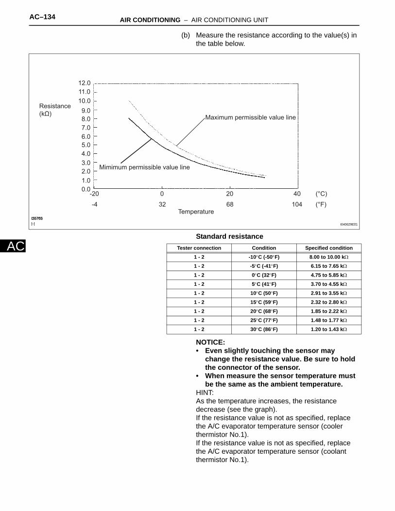
AC–134 AIR CONDITIONING – AIR CONDITIONING UNIT
AC
(b) Measure the resistance according to the value(s) in the table below.
Standard resistance
NOTICE:• Even slightly touching the sensor may
change the resistance value. Be sure to hold the connector of the sensor.
• When measure the sensor temperature must be the same as the ambient temperature.
HINT:As the temperature increases, the resistance decrease (see the graph).If the resistance value is not as specified, replace the A/C evaporator temperature sensor (cooler thermistor No.1).If the resistance value is not as specified, replace the A/C evaporator temperature sensor (coolant thermistor No.1).
0.01.02.03.04.05.06.07.08.09.0
10.011.012.0
-20 0 20 40
-4 32 68 104
(°C)
(°F)
Resistance (kΩ) Maximum permissible value line
Mimimum permissible value line
Temperature
I040629E01
Tester connection Condition Specified condition
1 - 2 -10°C (-50°F) 8.00 to 10.00 kΩ
1 - 2 -5°C (-41°F) 6.15 to 7.65 kΩ
1 - 2 0°C (32°F) 4.75 to 5.85 kΩ
1 - 2 5°C (41°F) 3.70 to 4.55 kΩ
1 - 2 10°C (50°F) 2.91 to 3.55 kΩ
1 - 2 15°C (59°F) 2.32 to 2.80 kΩ
1 - 2 20°C (68°F) 1.85 to 2.22 kΩ
1 - 2 25°C (77°F) 1.48 to 1.77 kΩ
1 - 2 30°C (86°F) 1.20 to 1.43 kΩ
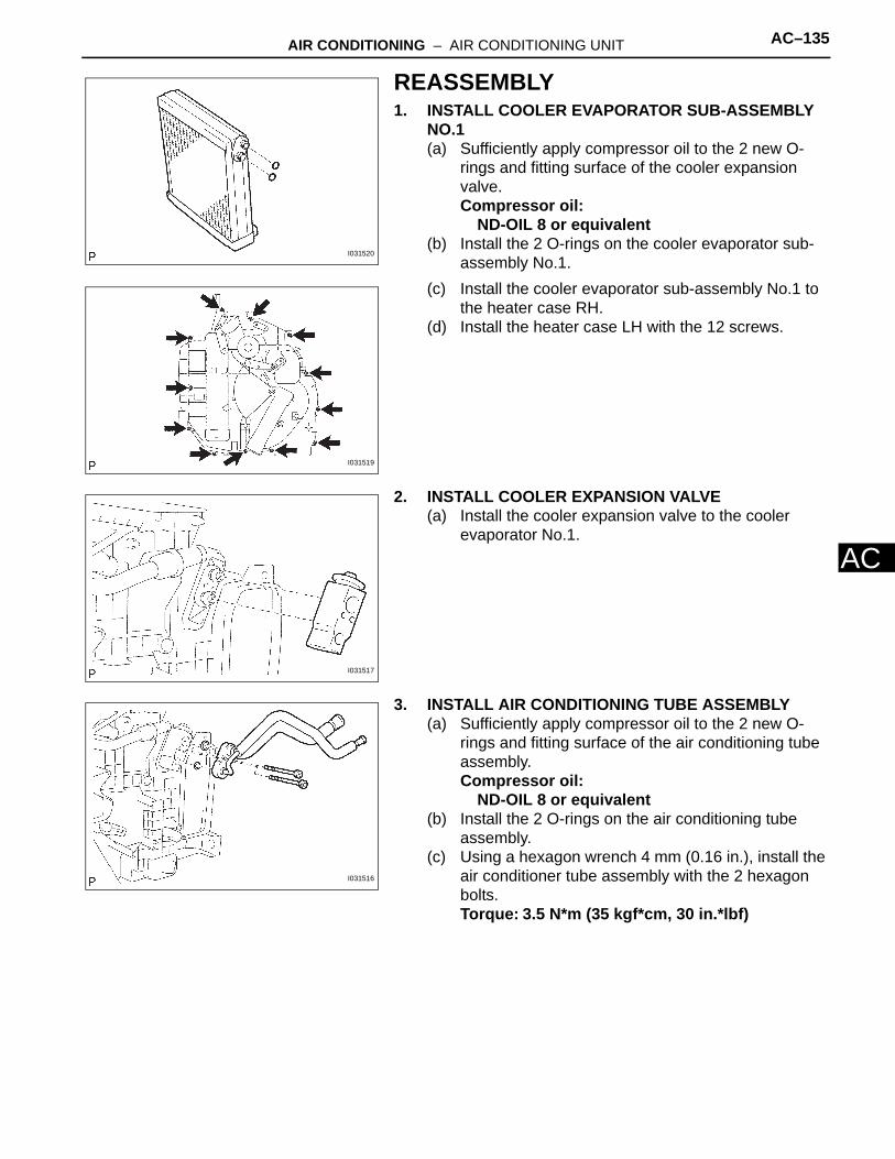
AIR CONDITIONING – AIR CONDITIONING UNIT AC–135
C
AREASSEMBLY1. INSTALL COOLER EVAPORATOR SUB-ASSEMBLY
NO.1(a) Sufficiently apply compressor oil to the 2 new O-
rings and fitting surface of the cooler expansion valve.Compressor oil:
ND-OIL 8 or equivalent(b) Install the 2 O-rings on the cooler evaporator sub-
assembly No.1.(c) Install the cooler evaporator sub-assembly No.1 to
the heater case RH.(d) Install the heater case LH with the 12 screws.
2. INSTALL COOLER EXPANSION VALVE(a) Install the cooler expansion valve to the cooler
evaporator No.1.
3. INSTALL AIR CONDITIONING TUBE ASSEMBLY(a) Sufficiently apply compressor oil to the 2 new O-
rings and fitting surface of the air conditioning tube assembly.Compressor oil:
ND-OIL 8 or equivalent(b) Install the 2 O-rings on the air conditioning tube
assembly.(c) Using a hexagon wrench 4 mm (0.16 in.), install the
air conditioner tube assembly with the 2 hexagon bolts.Torque: 3.5 N*m (35 kgf*cm, 30 in.*lbf)
I031520
I031519
I031517
I031516

AC–136 AIR CONDITIONING – AIR CONDITIONING UNIT
AC
(d) Install the packing.HINT:Securely attach so that a gap in the packing will not occur.
INSTALLATION1. INSTALL AIR CONDITIONING RADIATOR ASSEMBLY
(a) Install the air conditioning radiator assembly with the 2 nuts.Torque: 1.5 N*m (15 kgf*cm, 12 in.*lbf)
(b) Connect the connector.(c) Install the drain hose.
2. INSTALL DEFROSTER NOZZLE ASSEMBLY LOWER(a) Install the defroster nozzle assembly lower.
NOTICE:Install the pins in the order as shown in the illustration.
3. INSTALL BLOWER ASSEMBLY(a) Install the blower assembly with the 2 screws and 2
nuts.Torque: Nut
1.5 N*m (15 kgf*cm, 12 in.*lbf)
I031515
I040417
(2) (2)
(3) (3)
(1)
I031552E01
I038547
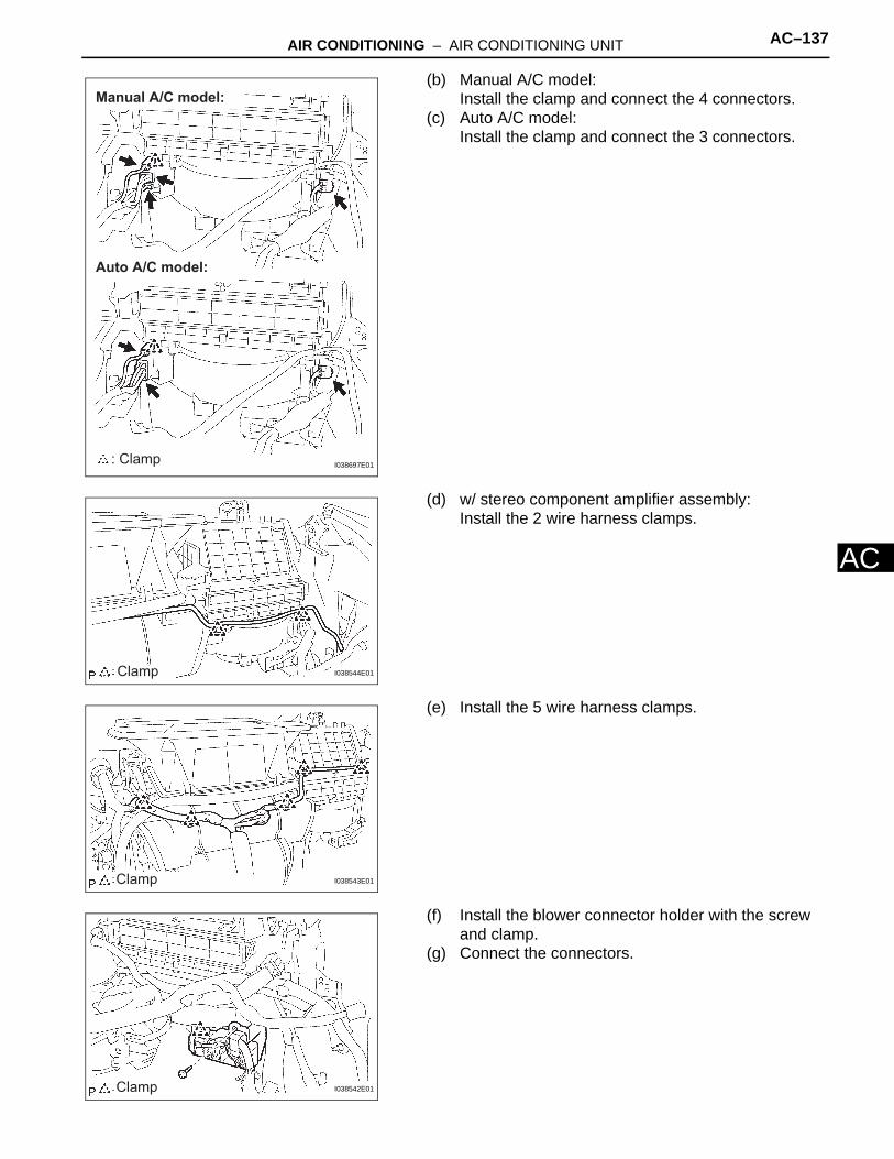
AIR CONDITIONING – AIR CONDITIONING UNIT AC–137
C
A(b) Manual A/C model:Install the clamp and connect the 4 connectors.
(c) Auto A/C model:Install the clamp and connect the 3 connectors.
(d) w/ stereo component amplifier assembly:Install the 2 wire harness clamps.
(e) Install the 5 wire harness clamps.
(f) Install the blower connector holder with the screw and clamp.
(g) Connect the connectors.
: Clamp
Manual A/C model:
Auto A/C model:
I038697E01
Clamp I038544E01
Clamp I038543E01
Clamp I038542E01

AC–138 AIR CONDITIONING – AIR CONDITIONING UNIT
AC
4. INSTALL INSTRUMENT PANEL REINFORCEMENT ASSEMBLY(a) Install the instrument panel reinforcement with the 7
bolts and 3 caps.
Torque: Bolt A20 N*m (204 kgf*cm, 15 ft.*lbf)
(b) Install the 3 earth wires with the 3 nuts.
(A)I038541E01
I038540

AIR CONDITIONING – AIR CONDITIONING UNIT AC–139
C
A(c) Install the 7 wire harness clamps.
5. INSTALL STEERING COLUMN ASSEMBLY(a) Install the steering column assembly with the 3 bolts
and 2 nuts.Torque: 21 N*m (210 kgf*cm, 15 ft.*lbf)
(b) Install the wire harness clamp and 3 connectors.
6. INSTALL INSTRUMENT PANEL JUNCTION BLOCK ASSEMBLY(a) Install the instrument panel junction block assembly
with the 3 nuts.Torque: 8.4 N*m (85 kgf*cm, 73 in.*lbf)
ClampI038484E01
I038482
Clamp I039252E01
I038480

AC–140 AIR CONDITIONING – AIR CONDITIONING UNIT
AC
7. INSTALL INSTRUMENT PANEL BRACE SUB-ASSEMBLY NO.2(a) Install the instrument panel brace sub-assembly No.
2 with the 2 nuts and bolt.
(b) Install the amplifier antenna assembly with the nut and clamp.
(c) Install the passenger side junction block with the nut and clamp.Torque: 8.4 N*m (85 kgf*cm, 73 in.*lbf)
(d) Install the earth wire with the bolt.
8. INSTALL INSTRUMENT FINISH PANEL RETAINER NO.1(a) Install the instrument finish panel retainer lower with
the 2 bolts.
I038478
ClampI038477E01
ClampI038476E01
I038475
I031502

AIR CONDITIONING – AIR CONDITIONING UNIT AC–141
C
A9. INSTALL INSTRUMENT PANEL BRACE SUB-ASSEMBLY NO.1(a) Install the instrument panel brace sub-assembly
No.1 with the nut and bolt.(b) Install the screw.
Torque: Screw9.8 N*m (100 kgf*cm, 87 in.*lbf)
(c) Install the wire harness with the 2 wire harness clamps.
(d) Install the connector holder with the nut.
(e) Install the 2 earth wires with the 2 bolts.
10. INSTALL INSTRUMENT PANEL SAFETY PADHINT:See page IP-14
11. INSTALL COOLER REFRIGERANT SUCTION HOSE NO.1(a) Remove the attached vinyl tape from the hose.(b) Coat a new O-ring with compressor oil and install it
to the hose.Compressor oil:
ND-OIL 8 or equivalent(c) Install the cooler refrigerant suction hose No.1 and
piping clamp.HINT:• Be sure to connect the hose securely.
I038474
ClampI038473E01
I038472
I038471
ConnectGap
Wrong
I006878E01

AC–142 AIR CONDITIONING – AIR CONDITIONING UNIT
AC
• After connection, check the fitting claw of the piping clamp.
12. REMOVE COOLER REFRIGERANT LIQUID PIPE AHINT:Install in the same way as the cooler refrigerant suction hose No.1.
13. ADD ENGINE COOLANTHINT:• 2AZ-FE (See page CO-8)• 3MZ-FE (See page CO-7)
14. CHARGE REFRIGERANT (See page AC-115)15. WARM UP ENGINE (See page AC-116)16. CHECK FOR ENGINE COOLANT LEAKS
HINT:• 2AZ-FE (See page CO-9)• 3MZ-FE (See page CO-8)
17. INSPECT LEAKAGE OF REFRIGERANT (See page AC-116)

AC–120 AIR CONDITIONING – AIR CONDITIONING UNIT
AC
HEATER & AIR CONDITIONING SYSTEMAIR CONDITIONINGAIR CONDITIONING UNITCOMPONENTS
AIR CONDITIONING RADIATOR ASSEMBLY
AIR DUCT REAR NO.1AIR DUCT REAR NO.2
BLOWER ASSEMBLY
COOLER REFRIGERANT LIQUID PIPE A
COOLER REFRIGERANT SUCTION HOSE NO.1
DEFROSTER NOZZLE ASSEMBLY LOWER
HEATER TO FOOT DUCT NO.1
HEATER TO FOOT DUCT NO.3
INSTRUMENT PANEL BRACE SUB-ASSEMBLY NO.1
INSTRUMENT PANEL BRACE SUB-ASSEMBLY NO.2
INSTRUMENT PANEL REINFORCEMENT ASSEMBLY
1.5 (15, 12 in.*lbf)
1.5 (15, 12 in.*lbf)
1.5 (15, 12 in.*lbf)
1.5 (15, 12 in.*lbf)9.8 (100, 87 in.*lbf)
20 (204, 15)
O-RING
O-RING
PIPING CLAMP
PIPING CLAMP
INSTRUMENT FINISH PANEL RETAINER LOWER
N*m (kgf*cm, ft.*lbf) : Specified torque Non-reusable part
Compressor oil ND-OIL 8 or equivalentC109679E01

AIR CONDITIONING – AIR CONDITIONING UNIT AC–121
C
AAIR CONDITIONING TUBE ASSEMBLY
AIR MIX DAMPER SERVO (AIR MIX DAMPER SERVO SUB-ASSEMBLY)(MANUAL AIR CONDITIONING)
AIR OUTLET CONTROL SERVOMOTOR (MODE DAMPER SERVO SUB-ASSEMBLY)(MANUAL AIR CONDITIONING)
COOLER EVAPORATOR SUB-ASSEMBLY NO.1
COOLER EXPANSION VALVE
COOLER THERMISTOR NO.1
HEARTER RADIATOR UNIT SUB-ASSEMBLY
N*m (kgf*cm, ft.*lbf) : Specified torque
Non-reusable partCompressor oil ND-OIL 8 or equivalent
3.5 (35, 30 in.*lbf)
O-RING
PIPING CLAMP
PIPING CLAMP
DRAIN HOSE
(EVAPORATOR TEMPERATURE SENSOR)
C109680E01

AC–148 AIR CONDITIONING – BLOWER UNIT
AC
INSPECTION1. INSPECT BLOWER RESISTOR
HINT:The blower resistor can be removed following the removal and disassembly procedure for the blower assembly (See page AC-145 and AC-144). (a) Measure the resistance according to the value(s) in
the table below.Standard resistance
If the resistance is not as specified, replace the blower resistor.
2. INSPECT AIR INLET CONTROL SERVOMOTOR (RECIRCULATION DAMPER SERVO SUB-ASSEMBLY)HINT:The air inlet control servomotor (recirculation damper servo sub-assembly) can be removed following the removal procedure for the blower assembly (See page AC-144). (a) Inspect servomotor operation.
(1) Connect the positive (+) lead from the battery to terminal 5 and negative (-) lead to terminal 1, then check that the arm turns to the "REC" side smoothly.
(2) Connect the positive (+) lead from the battery to terminal 5 and negative (-) lead to terminal 2, then check that the arm turns to the "FRS" side smoothly.If operations are not as specified, replace the servomotor.
3. INSPECT BLOWER W/FAN MOTOR SUB-ASSEMBLYHINT:The blower w/fan motor sub-assembly can be removed following the removal and disassembly procedure for the blower assembly. (See page AC-145 and AC-144). (a) Connect the positive (+) lead from the battery to
terminal 2 and negative (-) lead to terminal 1, then check that the motor operates smoothly.If operation is not as specified, replace the blower motor.
Blower Resistance Connector Front View:
B5
E032877E02
Tester Connection Specified Condition
1 - 2 1.398 to 1.605 Ω
1 - 3 0.465 to 0.535 Ω
1 - 4 3.069 to 3.531 Ω
Air Inlet Control Servomotor (Resirculation Damper Servo Sub-assembly) Connector Front View:
A18
FRS
REC
I031407E01
B3
12
Blower w/ Fan Motor Sub-assembly connector Front view:
I031402E01

AIR CONDITIONING – BLOWER UNIT AC–149
C
AREASSEMBLY1. INSTALL BLOWER W/FAN MOTOR SUB-ASSEMBLY2. INSTALL BLOWER MOTOR CONTROL3. INSTALL BLOWER RESISTOR4. INSTALL INSTRUMENT PANEL WIRE NO.35. INSTALL RECIRCULATION DAMPER SERVO SUB-
ASSEMBLY6. INSTALL COWL WIRE NO.27. INSTALL CLEAN AIR FILTERINSTALLATION1. INSTALL BLOWER ASSEMBLY
(a) Install the blower assembly with the 2 screws and 2 nuts.Torque: Nut
1.5 N*m (15 kgf*cm, 12 in.*lbf)
(b) Manual A/C model:Install the clamp and connect the 4 connectors.
(c) Auto A/C model:Install the clamp and connect the 3 connectors.
I038547
: Clamp
Manual A/C model:
Auto A/C model:
I038697E02

AC–150 AIR CONDITIONING – BLOWER UNIT
AC
(d) w/ stereo component amplifier assembly:Install the 2 wire harness clamps.
(e) Install the 5 wire harness clamps.
(f) Install the blower connector holder with the screw and clamp.
(g) Connect the connectors.
2. INSTALL INSTRUMENT PANEL SAFETY PADHINT:See page IP-14
2 ClampsI038544E02
5 ClampsI038543E02
2 ClampsI038542E04

AIR CONDITIONING – BLOWER UNIT AC–143
C
AHEATER & AIR CONDITIONING SYSTEMAIR CONDITIONINGBLOWER UNITCOMPONENTS
AIR INLET CONTROL SERVOMOTOR (RECIRCULATION DAMPER SERVO SUB-ASSEMBLY)
BLOWER ASSEMBLY
BLOWER MOTOR CONTROL
BLOWER RESISTOR
BLOWER W/FAN MOTOR SUB-ASSEMBLY
CLEAN AIR FILTER
COWL WIRE NO.2
HEATER TO FOOT DUCT NO.1
INSTRUMENT PANEL WIRE NO.3
AUTO A/C MODEL:
INSTRUMENT PANEL WIRE NO.3
FRONT COOLER FRAME
N*m (kgf*cm, ft.*lbf) : Specified torque
1.5 (15, 12 in.*lbf)
1.5 (15, 12 in.*lbf)
C109681E01
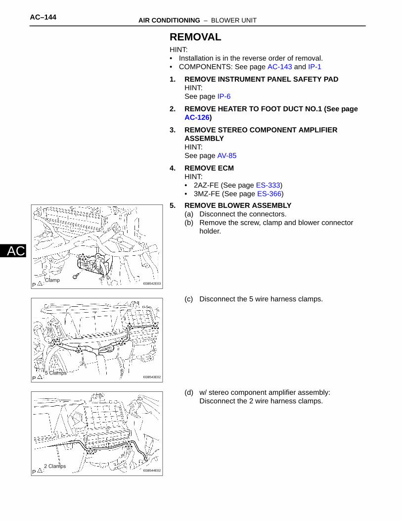
AC–144 AIR CONDITIONING – BLOWER UNIT
AC
REMOVALHINT:• Installation is in the reverse order of removal.• COMPONENTS: See page AC-143 and IP-1
1. REMOVE INSTRUMENT PANEL SAFETY PADHINT:See page IP-6
2. REMOVE HEATER TO FOOT DUCT NO.1 (See page AC-126)
3. REMOVE STEREO COMPONENT AMPLIFIER ASSEMBLYHINT:See page AV-85
4. REMOVE ECMHINT:• 2AZ-FE (See page ES-333)• 3MZ-FE (See page ES-366)
5. REMOVE BLOWER ASSEMBLY(a) Disconnect the connectors.(b) Remove the screw, clamp and blower connector
holder.
(c) Disconnect the 5 wire harness clamps.
(d) w/ stereo component amplifier assembly:Disconnect the 2 wire harness clamps.
ClampI038542E03
5 ClampsI038543E02
2 ClampsI038544E02
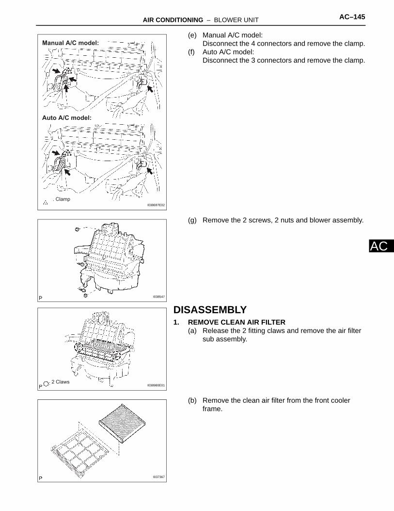
AIR CONDITIONING – BLOWER UNIT AC–145
C
A(e) Manual A/C model:Disconnect the 4 connectors and remove the clamp.
(f) Auto A/C model:Disconnect the 3 connectors and remove the clamp.
(g) Remove the 2 screws, 2 nuts and blower assembly.
DISASSEMBLY1. REMOVE CLEAN AIR FILTER
(a) Release the 2 fitting claws and remove the air filter sub assembly.
(b) Remove the clean air filter from the front cooler frame.
: Clamp
Manual A/C model:
Auto A/C model:
I038697E02
I038547
2 ClawsI038980E01
I037367
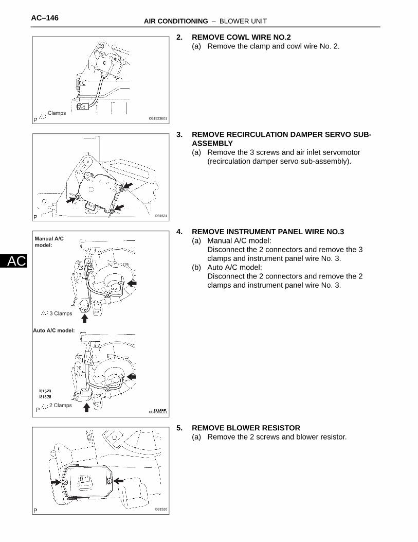
AC–146 AIR CONDITIONING – BLOWER UNIT
AC
2. REMOVE COWL WIRE NO.2(a) Remove the clamp and cowl wire No. 2.
3. REMOVE RECIRCULATION DAMPER SERVO SUB-ASSEMBLY(a) Remove the 3 screws and air inlet servomotor
(recirculation damper servo sub-assembly).
4. REMOVE INSTRUMENT PANEL WIRE NO.3(a) Manual A/C model:
Disconnect the 2 connectors and remove the 3 clamps and instrument panel wire No. 3.
(b) Auto A/C model:Disconnect the 2 connectors and remove the 2 clamps and instrument panel wire No. 3.
5. REMOVE BLOWER RESISTOR(a) Remove the 2 screws and blower resistor.
ClampsI031523E01
I031524
Manual A/C model:
Auto A/C model:
3 Clamps
2 ClampsI031585E01
I031526

AIR CONDITIONING – BLOWER UNIT AC–147
C
A6. REMOVE BLOWER MOTOR CONTROL(a) Remove the 2 screws and blower motor control.
7. REMOVE BLOWER W/FAN MOTOR SUB-ASSEMBLY(a) Remove the 3 screws and blower w/ fan motor sub-
assembly.
I031525
I031527
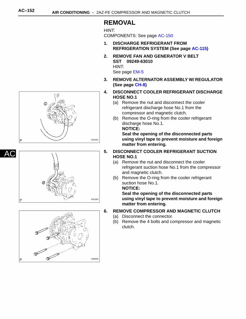
AC–152 AIR CONDITIONING – 2AZ-FE COMPRESSOR AND MAGNETIC CLUTCH
AC
REMOVALHINT:COMPONENTS: See page AC-150
1. DISCHARGE REFRIGERANT FROM REFRIGERATION SYSTEM (See page AC-115)
2. REMOVE FAN AND GENERATOR V BELTSST 09249-63010HINT:See page EM-5
3. REMOVE ALTERNATOR ASSEMBLY W/ REGULATOR (See page CH-8)
4. DISCONNECT COOLER REFRIGERANT DISCHARGE HOSE NO.1(a) Remove the nut and disconnect the cooler
refrigerant discharge hose No.1 from the compressor and magnetic clutch.
(b) Remove the O-ring from the cooler refrigerant discharge hose No.1.NOTICE:Seal the opening of the disconnected parts using vinyl tape to prevent moisture and foreign matter from entering.
5. DISCONNECT COOLER REFRIGERANT SUCTION HOSE NO.1(a) Remove the nut and disconnect the cooler
refrigerant suction hose No.1 from the compressor and magnetic clutch.
(b) Remove the O-ring from the cooler refrigerant suction hose No.1.NOTICE:Seal the opening of the disconnected parts using vinyl tape to prevent moisture and foreign matter from entering.
6. REMOVE COMPRESSOR AND MAGNETIC CLUTCH(a) Disconnect the connector.(b) Remove the 4 bolts and compressor and magnetic
clutch.
I031551
I031550
I038459

AIR CONDITIONING – 2AZ-FE COMPRESSOR AND MAGNETIC CLUTCH AC–153
C
A7. REMOVE MAGNET CLUTCH ASSEMBLY(a) Remove the bolt and bracket.(b) Place the compressor and magnetic clutch in a vise.
(c) Using SST, hold the magnet clutch hub.SST 95047-10400
(d) Remove the bolt, magnet clutch hub and magnet clutch washer.HINT:There is no set number of magnet clutch washers since they are used for adjusting.
(e) Using a snap ring expander, remove the snap ring and magnet clutch rotor.NOTICE:Do not damage the seal cover of the bearing when removing the snap ring.
(f) Disconnect the connector.
(g) Using a snap ring expander, remove the snap ring and magnet clutch starter.
I030371
SST
E066614E01
E037091
I030400

AC–154 AIR CONDITIONING – 2AZ-FE COMPRESSOR AND MAGNETIC CLUTCH
AC
INSPECTION1. INSPECT MAGNETIC CLUTCH CLEARANCE
(a) Set the dial indicator to the magnet clutch hub.(b) Connect the battery positive lead to terminal 3 of the
magnet clutch connector and the negative lead to the earth wire. Turn the magnet clutch on and off and measure the clearance.Standard clearance:
0.35 to 0.60 mm (0.014 to 0.024 in.)If the measured value is not within the standard range, remove the magnet clutch hub and adjust it with magnet clutch washers.NOTICE:Adjustment shall be performed with 3 or less magnet clutch washers.
(c) Remove the compressor and magnetic clutch from the vise.
(d) Install the bracket with the 2 bolts.
2. ADJUST COMPRESSOR OIL(a) When replacing the compressor and magnetic
clutch with a new one, after gradually removing the refrigerant gas from the service valve, drain the following amount of oil from the new compressor and magnetic clutch before installation.Amount of oil:
(Oil capacity inside new compressor and magnetic clutch: 120 + 15 cc (4.1 + 0.51 fl.oz.) ) - (Remaining oil amount in the removed compressor and magnetic clutch) = (Oil amount to be removed when replacing from the new compressor)
NOTICE:• When checking the compressor oil level,
observe the precautions on the cooler removal/installation.
• Because compressor oil remains in the pipes of the vehicle, if a new compressor and magnetic clutch is installed without removing some oil inside, the oil amount becomes too much, preventing heat exchange in the refrigerant cycle and causing refrigerant failure.
• If the remaining oil in the removed compressor and magnetic clutch is too small in volume, check for oil leakage.
• Be sure to use ND-OIL 8 for compressor oil.
I037852
I030363
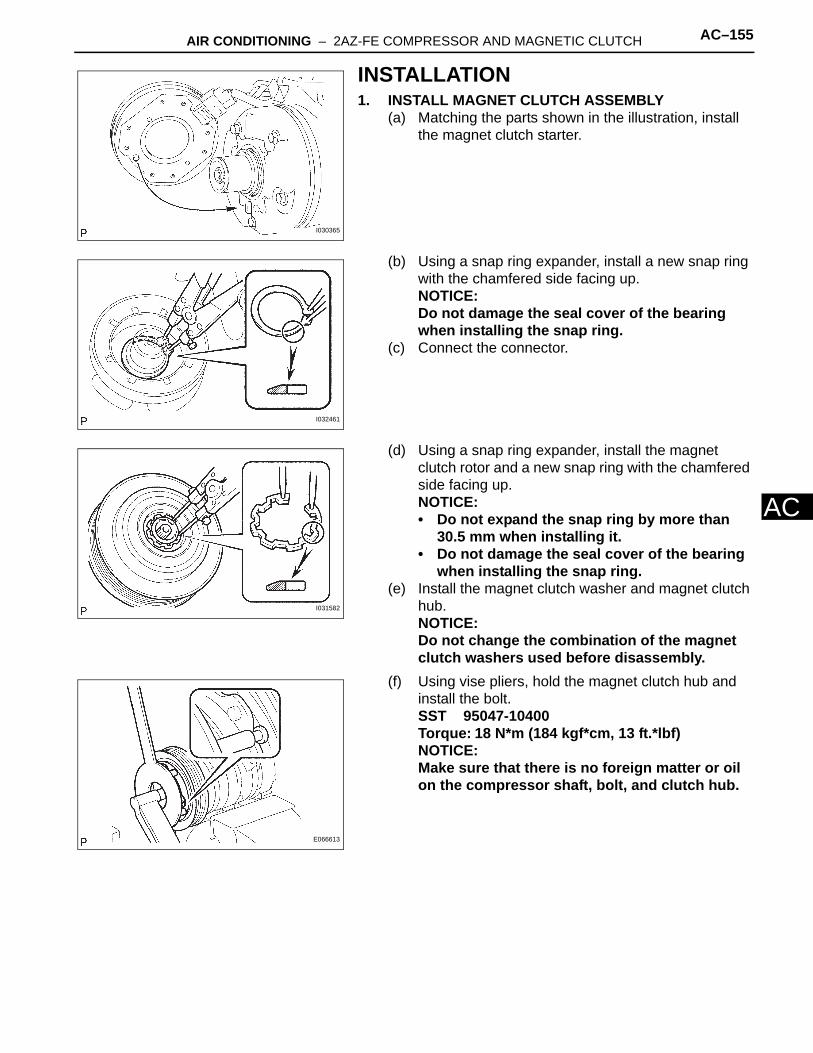
AIR CONDITIONING – 2AZ-FE COMPRESSOR AND MAGNETIC CLUTCH AC–155
C
AINSTALLATION1. INSTALL MAGNET CLUTCH ASSEMBLY
(a) Matching the parts shown in the illustration, install the magnet clutch starter.
(b) Using a snap ring expander, install a new snap ring with the chamfered side facing up.NOTICE:Do not damage the seal cover of the bearing when installing the snap ring.
(c) Connect the connector.
(d) Using a snap ring expander, install the magnet clutch rotor and a new snap ring with the chamfered side facing up.NOTICE:• Do not expand the snap ring by more than
30.5 mm when installing it.• Do not damage the seal cover of the bearing
when installing the snap ring.(e) Install the magnet clutch washer and magnet clutch
hub.NOTICE:Do not change the combination of the magnet clutch washers used before disassembly.
(f) Using vise pliers, hold the magnet clutch hub and install the bolt.SST 95047-10400Torque: 18 N*m (184 kgf*cm, 13 ft.*lbf)NOTICE:Make sure that there is no foreign matter or oil on the compressor shaft, bolt, and clutch hub.
I030365
I032461
I031582
E066613
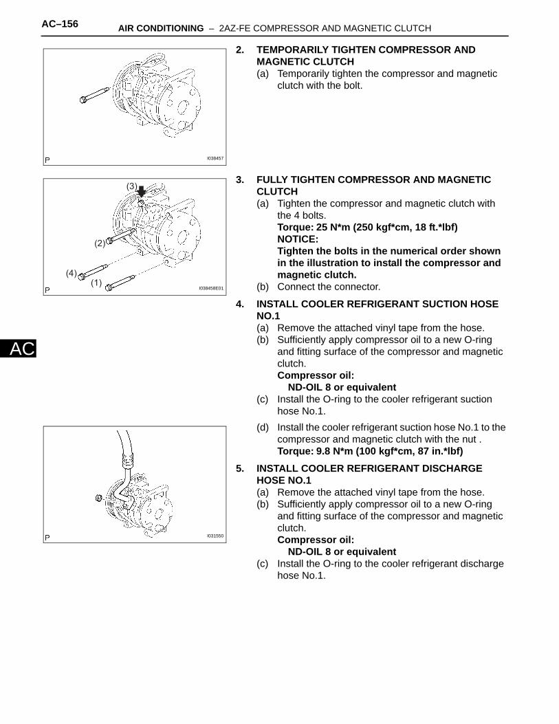
AC–156 AIR CONDITIONING – 2AZ-FE COMPRESSOR AND MAGNETIC CLUTCH
AC
2. TEMPORARILY TIGHTEN COMPRESSOR AND MAGNETIC CLUTCH(a) Temporarily tighten the compressor and magnetic
clutch with the bolt.
3. FULLY TIGHTEN COMPRESSOR AND MAGNETIC CLUTCH(a) Tighten the compressor and magnetic clutch with
the 4 bolts.Torque: 25 N*m (250 kgf*cm, 18 ft.*lbf)NOTICE:Tighten the bolts in the numerical order shown in the illustration to install the compressor and magnetic clutch.
(b) Connect the connector.
4. INSTALL COOLER REFRIGERANT SUCTION HOSE NO.1(a) Remove the attached vinyl tape from the hose.(b) Sufficiently apply compressor oil to a new O-ring
and fitting surface of the compressor and magnetic clutch.Compressor oil:
ND-OIL 8 or equivalent(c) Install the O-ring to the cooler refrigerant suction
hose No.1.(d) Install the cooler refrigerant suction hose No.1 to the
compressor and magnetic clutch with the nut .Torque: 9.8 N*m (100 kgf*cm, 87 in.*lbf)
5. INSTALL COOLER REFRIGERANT DISCHARGE HOSE NO.1(a) Remove the attached vinyl tape from the hose.(b) Sufficiently apply compressor oil to a new O-ring
and fitting surface of the compressor and magnetic clutch.Compressor oil:
ND-OIL 8 or equivalent(c) Install the O-ring to the cooler refrigerant discharge
hose No.1.
I038457
(1)
(2)
(3)
(4)I038458E01
I031550

AIR CONDITIONING – 2AZ-FE COMPRESSOR AND MAGNETIC CLUTCH AC–157
C
A(d) Install the cooler refrigerant discharge hose No.1 to the compressor and magnetic clutch with the nut.Torque: 9.8 N*m (100 kgf*cm, 87 in.*lbf)
6. INSTALL ALTERNATOR ASSEMBLY W/ REGULATOR (See page CH-14)
7. INSTALL FAN AND GENERATOR V BELTSST 09249-63010HINT:See page EM-5
8. CHARGE REFRIGERANT (See page AC-115)9. WARM UP ENGINE (See page AC-116)10. INSPECT LEAKAGE OF REFRIGERANT (See page
AC-116)
I031551
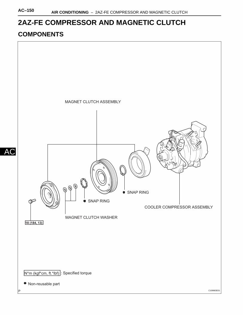
AC–150 AIR CONDITIONING – 2AZ-FE COMPRESSOR AND MAGNETIC CLUTCH
AC
HEATER & AIR CONDITIONING SYSTEMAIR CONDITIONING2AZ-FE COMPRESSOR AND MAGNETIC CLUTCHCOMPONENTS
COOLER COMPRESSOR ASSEMBLY
MAGNET CLUTCH ASSEMBLY
MAGNET CLUTCH WASHER
SNAP RING
SNAP RING
Non-reusable part
18 (184, 13)
N*m (kgf*cm, ft.*lbf) : Specified torque
C109683E01
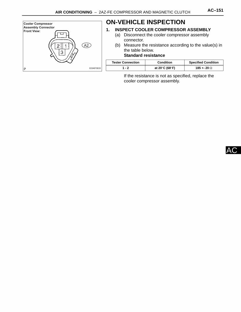
AIR CONDITIONING – 2AZ-FE COMPRESSOR AND MAGNETIC CLUTCH AC–151
C
AON-VEHICLE INSPECTION1. INSPECT COOLER COMPRESSOR ASSEMBLY
(a) Disconnect the cooler compressor assembly connector.
(b) Measure the resistance according to the value(s) in the table below.Standard resistance
If the resistance is not as specified, replace the cooler compressor assembly.
Cooler Compressor Assembly Connector Front View:
A2
E034870E03
Tester Connection Condition Specified Condition
1 - 2 at 20°C (68°F) 185 +- 20 Ω

AIR CONDITIONING – 3MZ-FE COMPRESSOR AND MAGNETIC CLUTCH AC–159
C
AREMOVALHINT:COMPONENTS : See page AC-157
1. DISCHARGE REFRIGERANT FROM REFRIGERATION SYSTEM (See page AC-115)
2. REMOVE V (COOLER COMPRESSOR TO CRANKSHAFT PULLEY) BELT NO.1SST 09249-63010HINT:See page EM-6
3. REMOVE ALTERNATOR ASSEMBLY W/ REGULATOR (See page CH-8)
4. REMOVE GENERATOR BELT ADJUSTING BAR(a) Remove the 2 nuts, bolt and generator belt
adjusting bar.
5. REMOVE COOLER REFRIGERANT DISCHARGE HOSE NO.1(a) Remove the nut and disconnect the cooler
refrigerant discharge hose No.1.(b) Remove the O-ring from the cooler refrigerant
discharge hose No.1.NOTICE:Seal the opening of the disconnected parts using vinyl tape to prevent moisture and foreign matter from entering.
6. REMOVE COOLER REFRIGERANT SUCTION HOSE NO.1(a) Remove the nut and disconnect the cooler
refrigerant suction hose No.1.(b) Remove the O-ring from the cooler refrigerant
suction hose No.1.NOTICE:Seal the opening of the disconnected parts using vinyl tape to prevent moisture and foreign matter from entering.
I037389
I037388
I031542

AC–160 AIR CONDITIONING – 3MZ-FE COMPRESSOR AND MAGNETIC CLUTCH
AC
7. REMOVE COMPRESSOR AND MAGNETIC CLUTCH(a) Disconnect the connector and clamp.(b) Remove the bolt, nut and cooler compressor
bracket.
(c) Remove the 3 bolts and compressor and magnetic clutch.
8. REMOVE MAGNET CLUTCH ASSEMBLY(a) Remove the screw, earth wire and cooler
compressor bracket.
(b) Remove the 2 bolts and the bracket.(c) Place the compressor and magnetic clutch in a vise.
NOTICE:Do not get the bracket and harness caught in the vise.
(d) Using SST, hold the magnet clutch hub.SST 95047-10400
(e) Remove the bolt, magnet clutch hub and magnet clutch washer.HINT:There is no set number of magnet clutch washers since they are used for adjusting.
I037390
I031546
E058517
I030363
SST
E066758E01

AIR CONDITIONING – 3MZ-FE COMPRESSOR AND MAGNETIC CLUTCH AC–161
C
A(f) Using a snap ring expander, remove the snap ring and magnet clutch rotor.NOTICE:Do not damage the seal cover of the bearing when removing the snap ring.
(g) Disconnect the connector.
(h) Using a snap ring expander, remove the snap ring and magnet clutch starter.
INSPECTION1. INSPECT MAGNETIC CLUTCH CLEARANCE
(a) Set the dial indicator to the magnet clutch hub.(b) Connect the battery positive lead to terminal 3 of the
magnet clutch connector and the negative lead to the earth wire. Turn the magnet clutch on and off and measure the clearance.Standard clearance:
0.35 to 0.60 mm (0.014 to 0.023 in.)If the measured value is not within the standard range, remove the magnet clutch hub and adjust it with magnet clutch washers.NOTICE:Adjustment shall be performed with 3 or less magnet clutch washers.
(c) Remove the compressor and magnetic clutch from the vise.
(d) Install the bracket with the 2 bolts.
2. ADJUST COMPRESSOR OIL(a) When replacing the compressor and magnetic
clutch with a new one, after gradually removing the refrigerant gas from the service valve, drain the following amount of oil from the new compressor and magnetic clutch before installation.Amount of oil:
(Oil capacity inside new compressor and magnetic clutch: 120 + 15 cc (4.1 + 0.51 fl.oz.) ) - (Remaining oil amount in the removed compressor and magnetic clutch) = (Oil amount to be removed when replacing from the new compressor)
E037091
I030400
I037852
I030363

AC–162 AIR CONDITIONING – 3MZ-FE COMPRESSOR AND MAGNETIC CLUTCH
AC
NOTICE:• When checking the compressor oil level,
observe the precautions on the cooler removal/installation.
• Because compressor oil remains in the pipes of the vehicle, if a new compressor and magnetic clutch is installed without removing some oil inside, the oil amount becomes too much, preventing heat exchange in the refrigerant cycle and causing refrigerant failure.
• If the remaining oil in the removed compressor and magnetic clutch is too small in volume, check for oil leakage.
• Be sure to use ND-OIL 8 for compressor oil.INSTALLATION1. INSTALL MAGNET CLUTCH ASSEMBLY
(a) Matching the parts shown in the illustration and install the magnet clutch starter.
(b) Using a snap ring expander, install a new snap ring with the chamfered side facing up.NOTICE:Do not damage the seal cover of the bearing when installing the snap ring.
(c) Connect the connector.
(d) Using a snap ring expander, install the magnet clutch rotor and a new snap ring with the chamfered side facing up.NOTICE:• Do not expand the snap ring by more than
30.5 mm when installing it.• Do not damage the seal cover of the bearing
when installing the snap ring.(e) Install the magnet clutch washer and magnet clutch
hub.NOTICE:Do not change the combination of the magnet clutch washers used before disassembly.
I030365
I032461
I031582
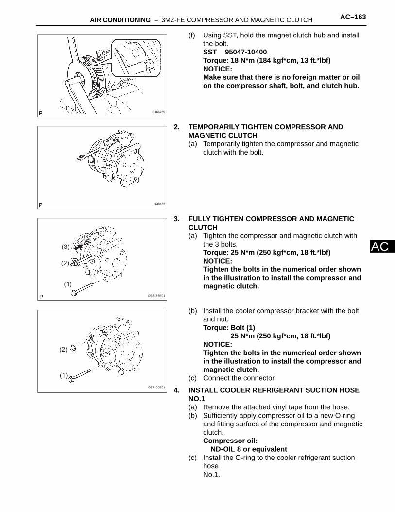
AIR CONDITIONING – 3MZ-FE COMPRESSOR AND MAGNETIC CLUTCH AC–163
C
A(f) Using SST, hold the magnet clutch hub and install the bolt.SST 95047-10400Torque: 18 N*m (184 kgf*cm, 13 ft.*lbf)NOTICE:Make sure that there is no foreign matter or oil on the compressor shaft, bolt, and clutch hub.
2. TEMPORARILY TIGHTEN COMPRESSOR AND MAGNETIC CLUTCH(a) Temporarily tighten the compressor and magnetic
clutch with the bolt.
3. FULLY TIGHTEN COMPRESSOR AND MAGNETIC CLUTCH(a) Tighten the compressor and magnetic clutch with
the 3 bolts.Torque: 25 N*m (250 kgf*cm, 18 ft.*lbf)NOTICE:Tighten the bolts in the numerical order shown in the illustration to install the compressor and magnetic clutch.
(b) Install the cooler compressor bracket with the bolt and nut.Torque: Bolt (1)
25 N*m (250 kgf*cm, 18 ft.*lbf)NOTICE:Tighten the bolts in the numerical order shown in the illustration to install the compressor and magnetic clutch.
(c) Connect the connector.
4. INSTALL COOLER REFRIGERANT SUCTION HOSE NO.1(a) Remove the attached vinyl tape from the hose.(b) Sufficiently apply compressor oil to a new O-ring
and fitting surface of the compressor and magnetic clutch.Compressor oil:
ND-OIL 8 or equivalent(c) Install the O-ring to the cooler refrigerant suction
hose No.1.
E066759
I038455
(1)
(2)
(3)
I038456E01
(1)
(2)
I037390E01

AC–164 AIR CONDITIONING – 3MZ-FE COMPRESSOR AND MAGNETIC CLUTCH
AC
(d) Install the cooler refrigerant suction hose No.1 to the compressor and magnetic clutch with the nut.Torque: 9.8 N*m (100 kgf*cm, 87 in.*lbf)
5. INSTALL COOLER REFRIGERANT DISCHARGE HOSE NO.1(a) Remove the attached vinyl tape from the hose.(b) Sufficiently apply compressor oil to a new O-ring
and fitting surface of the compressor and magnetic clutch.Compressor oil:
ND-OIL 8 or equivalent(c) Install the O-ring to the cooler refrigerant discharge
hose No.1.(d) Install the cooler refrigerant discharge hose No.1 to
the compressor and magnetic clutch with the nut.Torque: 9.8 N*m (100 kgf*cm, 87 in.*lbf)
6. INSTALL ALTERNATOR ASSEMBLY W/ REGULATOR (See page CH-14)
7. INSTALL V (COOLER COMPRESSOR TO CRANKSHAFT PULLEY) BELT NO.1SST 09249-63010HINT:See page EM-6
8. CHARGE REFRIGERANT (See page AC-115)9. WARM UP ENGINE (See page AC-116)10. INSPECT LEAKAGE OF REFRIGERANT (See page
AC-116)
I031542
I037388

AIR CONDITIONING – 3MZ-FE COMPRESSOR AND MAGNETIC CLUTCH AC–157
C
AHEATER & AIR CONDITIONING SYSTEMAIR CONDITIONING3MZ-FE COMPRESSOR AND MAGNETIC CLUTCHCOMPONENTS
COOLER COMPRESSOR ASSEMBLY
MAGNET CLUTCH ASSEMBLY
N*m (kgf*cm, ft.*lbf) : Specified torque
Non-reusable part
18 (184, 13)
COOLER COMPRESSOR BRACKET
MAGNET CLUTCH WASHER
SNAP RING
SNAP RING
C109682E01
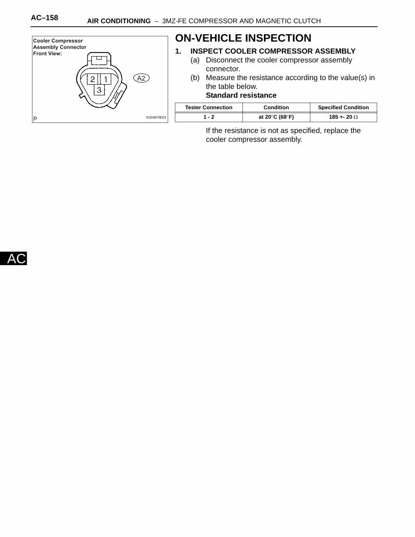
AC–158 AIR CONDITIONING – 3MZ-FE COMPRESSOR AND MAGNETIC CLUTCH
AC
ON-VEHICLE INSPECTION1. INSPECT COOLER COMPRESSOR ASSEMBLY
(a) Disconnect the cooler compressor assembly connector.
(b) Measure the resistance according to the value(s) in the table below.Standard resistance
If the resistance is not as specified, replace the cooler compressor assembly.
Cooler Compressor Assembly Connector Front View:
A2
E034870E03
Tester Connection Condition Specified Condition
1 - 2 at 20°C (68°F) 185 +- 20 Ω

AC–166 AIR CONDITIONING – CONDENSER
AC
REMOVALHINT:• Installation is in the reverse order of removal.• COMPONENTS: See page AC-164
1. DISCHARGE REFRIGERANT FROM REFRIGERATION SYSMTEM (See page AC-115)
2. DISCONNECT COOLER REFRIGERANT DISCHARGE HOSE NO.1(a) Remove the bolt and disconnect the cooler
refrigerant discharge hose No.1 from the cooler condenser assembly.
(b) Remove the O-ring from the cooler refrigerant discharge hose No.1.NOTICE:Seal the opening of the disconnected parts using vinyl tape to prevent moisture and foreign matter from entering.
3. DISCONNECT COOLER REFRIGERANT LIQUID PIPE ACO-17CO-16(a) Remove the bolt and disconnect the cooler
refrigerant liquid pipe A from the cooler condenser assembly.
(b) Remove the O-ring from the cooler refrigerant liquid pipe A.NOTICE:Seal the opening of the disconnected parts using vinyl tape to prevent moisture and foreign matter from entering.
4. REMOVE AIR CLEANER INLET ASSEMBLYHINT:• 2AZ-FE (See page CO-17)• 3MZ-FE (See page CO-16)
5. REMOVE RADIATOR SUPPORT UPPERHINT:• 2AZ-FE (See page CO-17)• 3MZ-FE (See page CO-16)
6. REMOVE COOLER CONDENSER ASSEMBLY(a) Remove the 2 nuts and cooler condenser assembly.
I037383
I037384
I037385

AIR CONDITIONING – CONDENSER AC–167
C
A7. REMOVE COOLER CONDENSER BRACKET NO.2(a) Remove the nut and cooler condenser bracket
No.2.
8. REMOVE COOLER CONDENSER BRACKET NO.1(a) Remove the nut and cooler condenser bracket
No.1.
INSTALLATION1. INSTALL COOLER CONDENSER BRACKET NO.2
(a) Install the cooler condenser bracket No.2 with the bolt.Torque: 4.4 N*m (45 kgf*cm, 39 in.*lbf)
2. INSTALL COOLER CONDENSER BRACKET NO.1(a) Install the cooler condenser bracket No.1 with the
bolt.Torque: 4.4 N*m (45 kgf*cm, 39 in.*lbf)
3. INSTALL COOLER CONDENSER ASSEMBLY(a) Install the cooler condenser assembly with the 2
nuts.Torque: 9.8 N*m (100 kgf*cm, 85 in.*lbf)
4. INSTALL RADIATOR SUPPORT UPPERHINT:• 2AZ-FE (See page CO-22)• 3MZ-FE (See page CO-20)
I037386
I038886
I037386
I038886
I037385
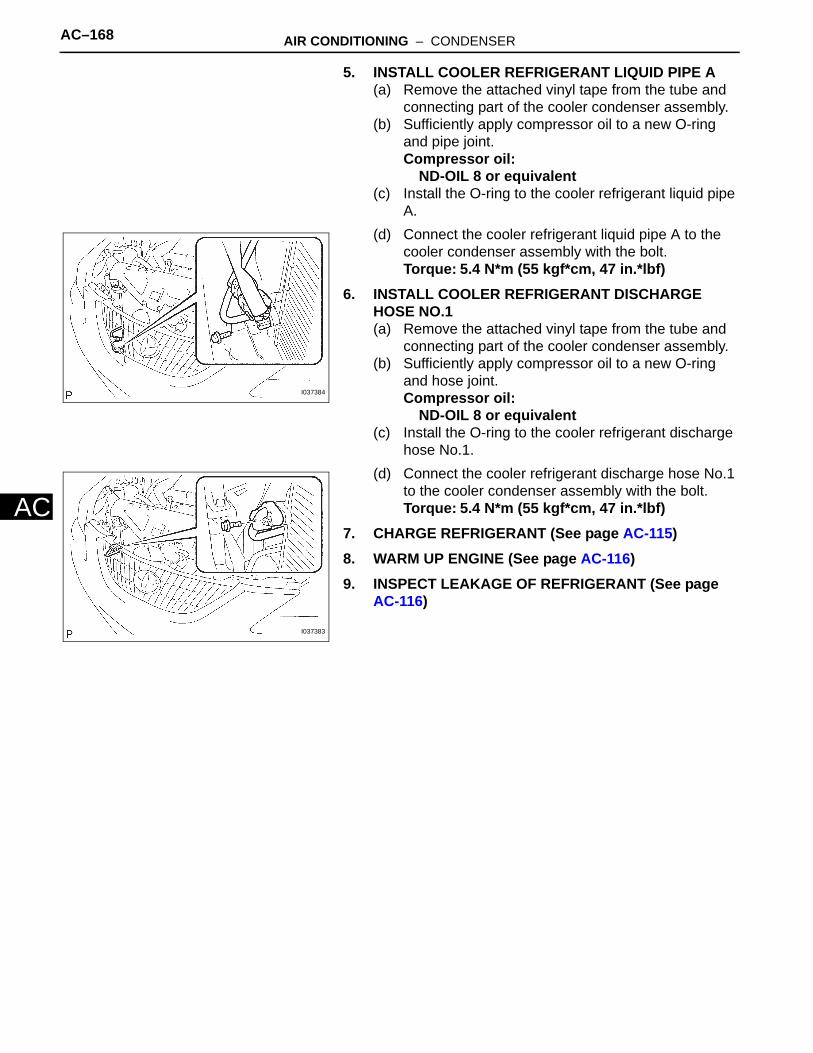
AC–168 AIR CONDITIONING – CONDENSER
AC
5. INSTALL COOLER REFRIGERANT LIQUID PIPE A(a) Remove the attached vinyl tape from the tube and
connecting part of the cooler condenser assembly.(b) Sufficiently apply compressor oil to a new O-ring
and pipe joint.Compressor oil:
ND-OIL 8 or equivalent(c) Install the O-ring to the cooler refrigerant liquid pipe
A.(d) Connect the cooler refrigerant liquid pipe A to the
cooler condenser assembly with the bolt.Torque: 5.4 N*m (55 kgf*cm, 47 in.*lbf)
6. INSTALL COOLER REFRIGERANT DISCHARGE HOSE NO.1(a) Remove the attached vinyl tape from the tube and
connecting part of the cooler condenser assembly.(b) Sufficiently apply compressor oil to a new O-ring
and hose joint.Compressor oil:
ND-OIL 8 or equivalent(c) Install the O-ring to the cooler refrigerant discharge
hose No.1.(d) Connect the cooler refrigerant discharge hose No.1
to the cooler condenser assembly with the bolt.Torque: 5.4 N*m (55 kgf*cm, 47 in.*lbf)
7. CHARGE REFRIGERANT (See page AC-115)8. WARM UP ENGINE (See page AC-116)9. INSPECT LEAKAGE OF REFRIGERANT (See page
AC-116)
I037384
I037383

AC–164 AIR CONDITIONING – CONDENSER
AC
HEATER & AIR CONDITIONING SYSTEMAIR CONDITIONINGCONDENSERCOMPONENTS
AIR CLEANER INLET ASSEMBLY
COOLER CONDENSER ASSEMBLY
COOLER CONDENSER BRACKET NO.1
COOLER CONDENSER BRACKET NO.2
COOLER REFRIGERANT DISCHARGE HOSE NO.1
COOLER REFRIGERANT LIQUID PIPE A
RADIATOR SUPPORT UPPER
AIR CLEANER INLET ASSEMBLY
AIR CLEANER INLET ASSEMBLY
Compressor oil ND-OIL 8 or equivalent
Non-reusable part
O-RING
O-RING
5.4 (55, 47 in.*lbf)
4.4 (45, 39 in.*lbf)
9.8 (100, 85 in.*lbf)
N*m (kgf*cm, ft.*lbf) : Specified torque
9.8 (100, 85in.*lbf)
4.4 (45, 39 in.*lbf)
HOOD LOCK RELEASE LEVER PROTECTOR
C109684E01
AIR CONDITIONING – CONDENSER AC–165
C
AON-VEHICLE INSPECTION1. INSPECT COOLER CONDENSER ASSEMBLY
(a) If the fins of the cooler condenser assembly are dirty, clean them with water and dry them with compressed air. NOTICE:Do not damage the fins of the cooler condenser assembly.
(b) If the fins of the cooler condenser assembly are bent, straighten them using a screwdriver or pliers.
2. INSPECT CONDENSER FOR REFRIGERANT LEAKAGE(a) Using a halogen leak detector, check the pipe joints
for gas leakage.(b) If gas leakage is detected in a joint, check the
torque of the joint.

AC–168 AIR CONDITIONING – PRESSURE SWITCH
AC
PRESSURE SWITCHON-VEHICLE INSPECTIONHINT:• The pressure switch is installed on the air conditioning
pipe on the high pressure side. • The pressure switch has two functions. It detects abnormal
pressure in the air conditioning cycle and turns the compressor on or off as necessary (magnet clutch control). It also turns the condenser fan on or off in accordance with pressure in the cycle (cooling fan control).
1. INSPECT PRESSURE SWITCH (for Magnet Clutch Control)HINT:• The switch on the low pressure side detects a drop in
refrigerant pressure, such as from refrigerant leakage, etc. and turns the magnet clutch off (*1)to prevent damage to the compressor.
• The switch on the high pressure side detects abnormally high pressure in the air conditioning cycle and turns the magnet clutch off (*1)to prevent damage to parts in the air conditioning cycle. (*1): The ECM turns the magnet clutch on or off upon receiving the signal from the pressure switch.
• As the pressure switch operates when there is a malfunction with the refrigerant pressure, its function cannot be inspected on-vehicle. Follow the procedures below to inspect it.
(a) Inspect refrigerant pressure in air conditioning cycle.(b) Read the manifold gauge pressure when these
conditions are established (Procedure "A"). Test conditions: • Temperature at the air inlet with the switch set at
RECIRC is 30 to 35°C (86 to 95°F)• Engine running at 1,500 rpm • Blower speed control switch at "HI" position• Temperature control dial at "COOL" position• Air conditioning switch ON• Fully open doorsStandard pressure:
Pressure on high pressure side: 1.37 to 1.57 Mpa (13.9 to 16.0 kgf-cm2, 198 to 228 psi)
HINT:• If the refrigerant pressure is not within the
standard value, inspect and repair the air conditioning cycle (See page AC-111).
• Proceed to step (See procedure "A") if the refrigerant pressure is within the specified range.
Low pressure side High pressure side
ON (Below 1.0 Ω)
196 kPa 3.140 kPa
OFF OFF
(10 kΩ or higher) (10 kΩ or higher)
E112612E02

AIR CONDITIONING – PRESSURE SWITCH AC–169
C
A• If the refrigerant pressure is below 196 KPa (2.0 kgf-cm2, 28 psi), the refrigerant amount in the air conditioning cycle may have decreased significantly for reasons such as a gas leakage.
(c) Check air conditioning operation. (1) Disconnect the pressure switch connector.(2) Connect terminals 1 and 4 of the connector of
the pressure switch on the vehicle wire harness side using a service wire.
(3) Start the engine.(4) Turn the air conditioning switch on and check
that the magnet clutch is turned on.(5) Check that the magnet clutch is turned off when
disconnecting terminals 1 and 4 (that are connected in the prior step).OK:
Terminals 1 and 4 connected:magnet clutch is on
Terminals 1 and 4 disconnected:magnet clutch is off
Replace the pressure switch if the magnet clutch is operated normally. Inspect and repair the wire harness between the pressure switch and the ECM.
2. INSPECT PRESSURE SWITCHHINT:The switch turns the condenser fan on or off in accordance with pressure in the cycle so that heat exchange in the condenser can be effectively within the normal pressure range.(a) Set the manifold gauge.(b) Disconnect the pressure switch connector and
connect terminals 1 and 4 using a tool such as a service wire.
(c) Connect the positive (+) lead from the ohmmeter to terminal 2 and the negative (-) lead to terminal 3.
(d) Start the engine and turn the air conditioning switch on.
(e) Check that the continuity between terminals 2 and 3 changes in accordance with the refrigerant pressure as shown in the illustration on the left. If operation is not as specified, replace the pressure switch.
Pressure Switch Connector Wire Harness View:
P2
I040667E02
Pressure Switch Connector Wire Harness View: Front View:
A5
1,226 KPa
1
2
4
3
(12.5 kgf*cm2), 178 psi
1,520 KPa(15.5 kgf*cm2), 220 psi
ON(Below 1.0 )OFF
(10 or higher)Ω
Ω
I040668E03

AC–170 AIR CONDITIONING – HEATER BLOWER MOTOR RELAY
AC
HEATER BLOWER MOTOR RELAYINSPECTION1. INSPECT HEATER BLOWER MOTOR RELAY
ASSEMBLY(a) Remove the relay (heater blower motor relay) from
the engine room R/B.(b) Measure the resistance according to the value(s) in
the table below.Standard resistance
If the resistance is not as specified, replace the blower motor relay.
1
2 3
5
1 2
35
Z018060E02
Terminal No. Condition Specified Condition
3 - 5 Always 10 kΩ or higher
3 - 5When battery voltage applied to terminals 1
and 2Below 1 Ω

AIR CONDITIONING – MAGNETIC CLUTCH RELAY AC–171
AC
MAGNETIC CLUTCH RELAYINSPECTION1. INSPECT MAGNET-CLUTCH RELAY
(a) Remove the relay (magnet clutch relay) from the engine room R/B.
(b) Measure the resistance according to the value(s) in the table below.Standard resistance
If the resistance is not as specified, replace the magnet clutch relay.
E050315
Tester Connection Condition Specified Condition
3 - 5 Always 10 kΩ or higher
3 - 5When battery voltage applied to terminals 1
and 2Below 1 Ω
AIR CONDITIONING – AIR CONDITIONING CONTROL ASSEMBLY AC–175
C
AINSPECTION1. INSPECT AIR CONDITIONING CONTROL ASSEMBLY
(AUTO AIR CONDITIONING)HINT:See page AC-2.

AC–176 AIR CONDITIONING – AIR CONDITIONING CONTROL ASSEMBLY
AC
REASSEMBLY1. INSTALL AIR CONDITIONER AMPLIFIER ASSEMBLY2. INSTALL AIR CONDITIONING CONTROL ASSEMBLY3. INSTALL CENTER CLUSTER INTEGRATION PANEL
ASSEMBLY (w/o Navigation System)4. REMOVE CENTER CLUSTER INTEGRATION PANEL
ASSEMBLY (w/ Navigation System)5. INSTALL INSTRUMENT CLUSTER FINISH PANEL
SUB-ASSEMBLY CENTER6. INSTALL CONSOLE PANEL SUB-ASSEMBLY UPPER7. INSTALL CONSOLE UPPER REAR PANEL SUB-
ASSEMBLY8. INSTALL COMBINATION METER ASSEMBLY9. INSTALL INSTRUMENT CLUSTER FINISH PANEL
SUB-ASSEMBLY10. INSTALL INSTRUMENT PANEL REGISTER
ASSEMBLY NO.111. INSTALL INSTRUMENT PANEL FINISH PANEL
LOWER12. INSTALL INSTRUMENT PANEL FINISH PLATE13. INSTALL INSTRUMENT CLUSTER FINISH PANEL
LOWER
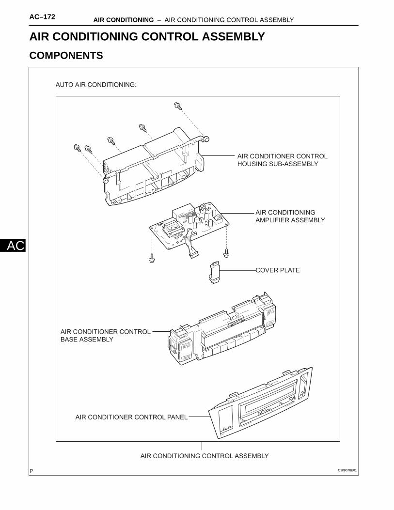
AC–172 AIR CONDITIONING – AIR CONDITIONING CONTROL ASSEMBLY
AC
HEATER & AIR CONDITIONING SYSTEMAIR CONDITIONINGAIR CONDITIONING CONTROL ASSEMBLYCOMPONENTS
AIR CONDITIONING AMPLIFIER ASSEMBLY
AIR CONDITIONING CONTROL ASSEMBLY
AIR CONDITIONER CONTROL PANEL
AIR CONDITIONER CONTROL BASE ASSEMBLY
COVER PLATE
AIR CONDITIONER CONTROL HOUSING SUB-ASSEMBLY
AUTO AIR CONDITIONING:
C109678E01
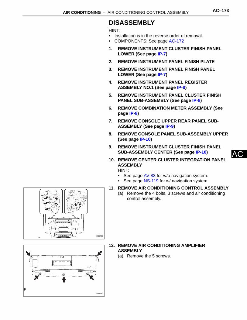
AIR CONDITIONING – AIR CONDITIONING CONTROL ASSEMBLY AC–173
C
ADISASSEMBLYHINT:• Installation is in the reverse order of removal.• COMPONENTS: See page AC-172
1. REMOVE INSTRUMENT CLUSTER FINISH PANEL LOWER (See page IP-7)
2. REMOVE INSTRUMENT PANEL FINISH PLATE3. REMOVE INSTRUMENT PANEL FINISH PANEL
LOWER (See page IP-7)4. REMOVE INSTRUMENT PANEL REGISTER
ASSEMBLY NO.1 (See page IP-8)5. REMOVE INSTRUMENT PANEL CLUSTER FINISH
PANEL SUB-ASSEMBLY (See page IP-8)6. REMOVE COMBINATION METER ASSEMBLY (See
page IP-8)7. REMOVE CONSOLE UPPER REAR PANEL SUB-
ASSEMBLY (See page IP-9)8. REMOVE CONSOLE PANEL SUB-ASSEMBLY UPPER
(See page IP-10)9. REMOVE INSTRUMENT CLUSTER FINISH PANEL
SUB-ASSEMBLY CENTER (See page IP-10)10. REMOVE CENTER CLUSTER INTEGRATION PANEL
ASSEMBLYHINT:• See page AV-83 for w/o navigation system.• See page NS-119 for w/ navigation system.
11. REMOVE AIR CONDITIONING CONTROL ASSEMBLY(a) Remove the 4 bolts, 3 screws and air conditioning
control assembly.
12. REMOVE AIR CONDITIONING AMPLIFIER ASSEMBLY(a) Remove the 5 screws.
I038460
I038461
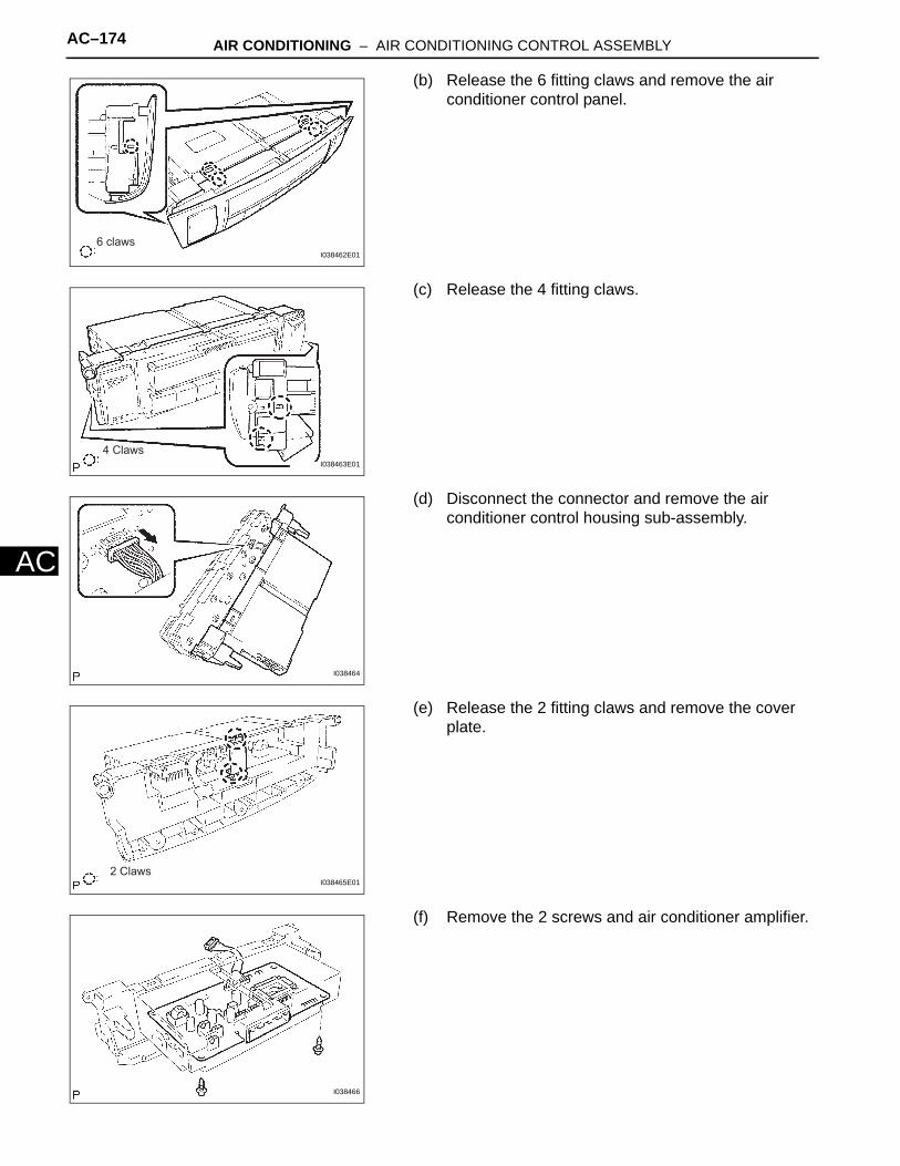
AC–174 AIR CONDITIONING – AIR CONDITIONING CONTROL ASSEMBLY
AC
(b) Release the 6 fitting claws and remove the air conditioner control panel.
(c) Release the 4 fitting claws.
(d) Disconnect the connector and remove the air conditioner control housing sub-assembly.
(e) Release the 2 fitting claws and remove the cover plate.
(f) Remove the 2 screws and air conditioner amplifier.
6 clawsI038462E01
4 ClawsI038463E01
I038464
2 ClawsI038465E01
I038466
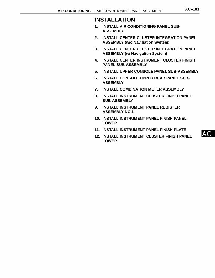
AIR CONDITIONING – AIR CONDITIONING PANEL ASSEMBLY AC–181
C
AINSTALLATION1. INSTALL AIR CONDITIONING PANEL SUB-
ASSEMBLY2. INSTALL CENTER CLUSTER INTEGRATION PANEL
ASSEMBLY (w/o Navigation System)3. INSTALL CENTER CLUSTER INTEGRATION PANEL
ASSEMBLY (w/ Navigation System)4. INSTALL CENTER INSTRUMENT CLUSTER FINISH
PANEL SUB-ASSEMBLY5. INSTALL UPPER CONSOLE PANEL SUB-ASSEMBLY6. INSTALL CONSOLE UPPER REAR PANEL SUB-
ASSEMBLY7. INSTALL COMBINATION METER ASSEMBLY8. INSTALL INSTRUMENT CLUSTER FINISH PANEL
SUB-ASSEMBLY9. INSTALL INSTRUMENT PANEL REGISTER
ASSEMBLY NO.110. INSTALL INSTRUMENT PANEL FINISH PANEL
LOWER11. INSTALL INSTRUMENT PANEL FINISH PLATE12. INSTALL INSTRUMENT CLUSTER FINISH PANEL
LOWER
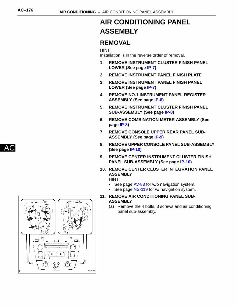
AC–176 AIR CONDITIONING – AIR CONDITIONING PANEL ASSEMBLY
AC
AIR CONDITIONING PANEL ASSEMBLYREMOVALHINT:Installation is in the reverse order of removal.
1. REMOVE INSTRUMENT CLUSTER FINISH PANEL LOWER (See page IP-7)
2. REMOVE INSTRUMENT PANEL FINISH PLATE3. REMOVE INSTRUMENT PANEL FINISH PANEL
LOWER (See page IP-7)4. REMOVE NO.1 INSTRUMENT PANEL REGISTER
ASSEMBLY (See page IP-8)5. REMOVE INSTRUMENT CLUSTER FINISH PANEL
SUB-ASSEMBLY (See page IP-8)6. REMOVE COMBINATION METER ASSEMBLY (See
page IP-8)7. REMOVE CONSOLE UPPER REAR PANEL SUB-
ASSEMBLY (See page IP-9)8. REMOVE UPPER CONSOLE PANEL SUB-ASSEMBLY
(See page IP-10)9. REMOVE CENTER INSTRUMENT CLUSTER FINISH
PANEL SUB-ASSEMBLY (See page IP-10)10. REMOVE CENTER CLUSTER INTEGRATION PANEL
ASSEMBLYHINT:• See page AV-83 for w/o navigation system.• See page NS-119 for w/ navigation system.
11. REMOVE AIR CONDITIONING PANEL SUB-ASSEMBLY(a) Remove the 4 bolts, 3 screws and air conditioning
panel sub-assembly.
I038468
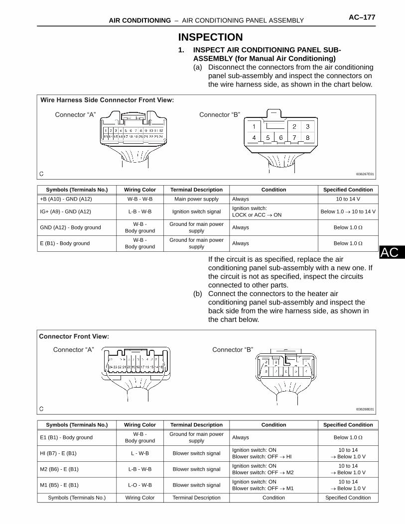
AIR CONDITIONING – AIR CONDITIONING PANEL ASSEMBLY AC–177
C
AINSPECTION1. INSPECT AIR CONDITIONING PANEL SUB-
ASSEMBLY (for Manual Air Conditioning)(a) Disconnect the connectors from the air conditioning
panel sub-assembly and inspect the connectors on the wire harness side, as shown in the chart below.
If the circuit is as specified, replace the air conditioning panel sub-assembly with a new one. If the circuit is not as specified, inspect the circuits connected to other parts.
(b) Connect the connectors to the heater air conditioning panel sub-assembly and inspect the back side from the wire harness side, as shown in the chart below.
Wire Harness Side Connnector Front View:
Connector “A” Connector “B”
I036267E01
Symbols (Terminals No.) Wiring Color Terminal Description Condition Specified Condition
+B (A10) - GND (A12) W-B - W-B Main power supply Always 10 to 14 V
IG+ (A9) - GND (A12) L-B - W-B Ignition switch signal Ignition switch: LOCK or ACC → ON Below 1.0 → 10 to 14 V
GND (A12) - Body ground W-B - Body ground
Ground for main power supply Always Below 1.0 Ω
E (B1) - Body ground W-B - Body ground
Ground for main power supply Always Below 1.0 Ω
Connector Front View:
Connector “A” Connector “B”
I036268E01
Symbols (Terminals No.) Wiring Color Terminal Description Condition Specified Condition
E1 (B1) - Body ground W-B - Body ground
Ground for main power supply Always Below 1.0 Ω
HI (B7) - E (B1) L - W-B Blower switch signal Ignition switch: ONBlower switch: OFF → HI
10 to 14 → Below 1.0 V
M2 (B6) - E (B1) L-B - W-B Blower switch signal Ignition switch: ONBlower switch: OFF → M2
10 to 14 → Below 1.0 V
M1 (B5) - E (B1) L-O - W-B Blower switch signal Ignition switch: ONBlower switch: OFF → M1
10 to 14→ Below 1.0 V
Symbols (Terminals No.) Wiring Color Terminal Description Condition Specified Condition

AC–178 AIR CONDITIONING – AIR CONDITIONING PANEL ASSEMBLY
AC
If the circuit is as specified, replace the air conditioning panel sub-assembly with a new one. If the circuit is not as specified, inspect the circuits connected to other parts.
LO (B3) - E (B1) L-W - W-B Blower switch signal Ignition switch: ONBlower switch: OFF → LO
10 to 14 → Below 1.0 V
A/CB (A2) - GND (A12) L-B - W-B Blower switch signalIgnition switch: ONBlower switch: OFF → ON (LO, M1, M2, HI)
0 → 10 to 14 V
+B (A10) - GND (A12) W-R - W-B Main power supply Always 10 to 14 V
IG+ (A9) - GND (A12) L-B - W-B Ignition switch signal Ignition switch: LOCK or ACC → ON 0 → 10 to 14 V
REC (A5) - GND (A12) L - W-B Recirculation/Fresh switch signal
Ignition switch: ONRecirculation/Fresh switch:FRESH → RECIRCULATION
Below 1.0 → 10 to 14 V
FRS (A6) - GND (A12) R-L - W-B Recirculation/Fresh switch signal
Ignition switch: ONRecirculation/Fresh switch:RECIRCULATION → FRESH
Below 1.0 → 10 to 14 V
DEF (A20) - GND (A12) B-W - W-B Mode switch signalIgnition switch: ONMode select switch:Except DEF → DEF
Below 1.0 → 10 to 14 V
F/D (A19) - GND (A12) LG-R - W-B Mode switch signalIgnition switch: ONMode select switch:Except FACE/DEF → FACE/DEF
Below 1.0 → 10 to 14 V
FOOT (A18) - GND (A12) L-R - W-B Mode switch signalIgnition switch: ONMode select switch:Except FOOT → FOOT
Below 1.0 → 10 to 14 V
B/L (A17) - GND (A12) BR-W - W-B Mode switch signalIgnition switch: ONMode select switch:Except BI LEVEL → BI LEVEL
Below 1.0 → 10 to 14 V
FACE (A16) - GND (A12) GR - W-B Mode switch signalIgnition switch: ONMode select switch:Except FACE → FACE
Below 1.0 → 10 to 14 V
TCOL (A3) - GND (A12) P-L - W-B Temperature switch signal
Ignition switch: ONTemperature select switch:MAX. HOT → MAX. COOL
Below 1.0 → 10 to 14 V
THOT (A4) - GND (A12) P - W-B Temperature switch signal
Ignition switch: ONTemperature select switch:MAX. COOL → MAX. HOT
Below 1.0 → 10 to 14 V
S5 (A21) - GND (A12) V - W-BPower supply for air mix
damper servo sub-assembly
Ignition switch: LOCK → ON 0 → 5.0 V
SG (A7) - Body ground B-R - W-BGround for air mix damper servo sub-
assemblyAlways Below 1.0 Ω
TEST (A22) - SG (A7) G-B - B-R Temperature switch signal
Ignition switch: ONTemperature select switch:MAX. HOT → MAX. COOL
Below 1.0 → Above 4.0 V
A/C (A23) - GND (A12) W - W-B A/C switch signal
Ignition switch: ONBlower switch: ON (LO, M1, M2, HI)A/C switch: OFF → ON
Below 2.0 → Above 6.0 V
ACID (A1) - GND (A12) Y-B - W-B A/C switch signal
Ignition switch: ONBlower switch: ON (LO, M1, M2, HI)A/C switch: OFF → ON
Below 1.0 → 10 to 14 V
GND (A12) - Body ground W-B - Body ground
Ground for main power supply Always Below 1.0 Ω
Symbols (Terminals No.) Wiring Color Terminal Description Condition Specified Condition

AIR CONDITIONING – AIR CONDITIONING PANEL ASSEMBLY AC–179
C
A2. INSPECT ECM (for Manual Air Conditioning)
*1: 2AZ-FE*2: 3MZ-FE
12 1234567 1234 123456 5634567 7
17 16 15 14 13 12 11 10 9 8 17 1716 15 141819 13 12 11 10 9 8 716 15 16 1514 13 12 11 10 9 814 13 12 11 10 98
23 2225 2427 26
27 26
21 20
31 31 3130 29 28 30 3029 28 29 2835 34 35 3433 32 33 3227 26 25 24 23 22 21 20 19 18 27 26 25 24 25 2423 22 21 20 19 18 23 22 21 20 19 1817
34 33 32 31 30 29 28
2AZ-FE Engine: Connector Front View:
3MZ-FE Engine: Connector Front View:
Connector “E” Connector “D” Connector “C” Connector “B” Connector “A”
E8 E7 E5 E4
E113077E01
Symbols (Terminals No.) Wiring Color Terminal Description Condition Specified Condition
ACMG (C2) - Body ground (*1) L-W - Body ground Pressure switch signal
Start engine. Refrigerant pressure: Normally → Less than 196 kPa (2.0 kgf*cm2, 28 psi) or more than 3,140 kPa (32.0 kgf*cm2, 455 psi)
Below 1.0 → 10 to 14 V
HP (B1) - Body ground (*2) L-B - Body ground Pressure switch signal
Start engine. Refrigerant pressure: Normally → Less than 196 kPa (2.0 kgf*cm2, 28 psi) or more than 3,140 kPa (32.0 kgf*cm2, 455 psi)
Below 1.0 → 10 to 14 V
A/CS (B30) - Body ground (*1) W - Body ground A/C switch signal Ignition switch: ON
A/C switch: OFF → ON10 to 14 V
→ Below 1.0
A/CS (B31) - Body ground (*2) W - Body ground A/C switch signal Ignition switch: ONA/C switch: OFF → ON
0 → → Below 1.0 V
ACLD (B33) - Body ground Y-B - Body ground Magnet clutch signal Ignition switch: ON
Magnet clutch: OFF → ON 10 to 14 → Below 1.0 V
THE (B32) - E2 (E28) L-W - Body ground
Evaporator temperature signal
Ignition switch: ONEvaporator temperature:0°C (32°F) → 15°C (59°F)
2.0 to 2.4 → 1.4 to 1.8 V
E2 (E28) - Body ground BR - Body ground
Ground for main power supply Always Below 1.0 Ω
LCKI (C23) - Body ground W-L - Body ground Magnet clutch signal Ignition switch: ON
Magnet clutch: OFF → ONPulse generation(see waveform 1)

AC–180 AIR CONDITIONING – AIR CONDITIONING PANEL ASSEMBLY
AC
(a) waveform 1:Measure the waveform between terminal LCKI (C23) of the ECM and body ground.OK:
Waveform operate as shown in the illustration.If the waveform is as specified, replace the ECM with a new one. If the waveform is not as specified, inspect the circuits connected to other parts.
200 mV/ Division
GND
10 msec./Division I031459E03