ags tractor mounted sprayers … · sprayer ags 200en with a spraying boom , 300 en. navodilo za...
TRANSCRIPT

Cleveland Sprayers Ltd. AGS TRACTOR MOUNTED SPRAYERS
INSTRUCTIONS FOR USE www.clevelandsprayers.com
AGS 200, 350,450
AGS 200, AGS 200 EN, AGS 300 EN 1
CONTENTS:
EC STATEMENT OF CONFORMITY ...................................................................................... 3
CERTIFICATE OF CONFORMITY .......................................................................................... 4
1 IN GENERAL ................................................................................................................... 7
2 INSTRUCTIONS FOR SAFE OPERATION AND SAFETY WARNINGS ......................... 7
3 LABELS WITH SAFETY PRECAUTIONS AND INSTRUCTIONS FOR USE ................ 15
4 DESCRIPTION ............................................................................................................... 17
5 HOW TO CONNECT THE SPRAYER TO THE TRACTOR ........................................... 20
6 MOUNTING OF THE DRIVE SHAFT (CARDAN SHAFT) .............................................. 21
7 DETAILED DESCRIPTION WITH INSTRUCTIONS FOR USE ..................................... 22
8 ADDITIONAL EQUIPMENT ........................................................................................... 26
9 FLOW REGULATOR ..................................................................................................... 31
10 PUMPS ....................................................................................................................... 34
11 SPRAYING BOOMS ................................................................................................... 36
12 POSSIBLE ERRORS ................................................................................................. 42
13 TECHNICAL DATA..................................................................................................... 43
14 TYPES OF NOZZLES IN AGRICULTURE ................................................................. 47
15 TABLES............................................................ NAPAKA! ZAZNAMEK NI DEFINIRAN.
CATALOGUE WITH COMPONENT AND SPARE PARTS ............... NAPAKA! ZAZNAMEK NI DEFINIRAN.
AGS 200, 350,450
AGS 200, AGS 200 EN, AGS 300 EN 2
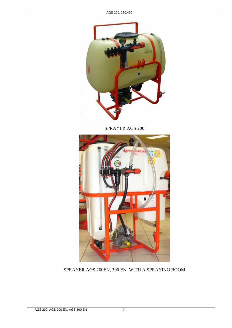
SPRAYER AGS 200
SPRAYER AGS 200EN, 300 EN WITH A SPRAYING BOOM
NAVODILO ZA UPORABO
AGS 200, AGS 200 EN, AGS 300 EN 3
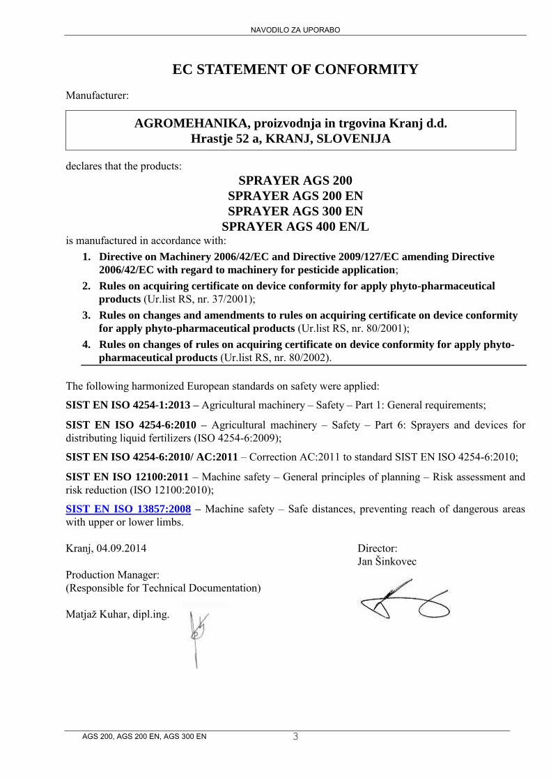
EC STATEMENT OF CONFORMITY
Manufacturer:
AGROMEHANIKA, proizvodnja in trgovina Kranj d.d.
Hrastje 52 a, KRANJ, SLOVENIJA declares that the products:
SPRAYER AGS 200
SPRAYER AGS 200 EN
SPRAYER AGS 300 EN
SPRAYER AGS 400 EN/L is manufactured in accordance with:
1. Directive on Machinery 2006/42/EC and Directive 2009/127/EC amending Directive
2006/42/EC with regard to machinery for pesticide application; 2. Rules on acquiring certificate on device conformity for apply phyto-pharmaceutical
products (Ur.list RS, nr. 37/2001); 3. Rules on changes and amendments to rules on acquiring certificate on device conformity
for apply phyto-pharmaceutical products (Ur.list RS, nr. 80/2001); 4. Rules on changes of rules on acquiring certificate on device conformity for apply phyto-
pharmaceutical products (Ur.list RS, nr. 80/2002). The following harmonized European standards on safety were applied:
SIST EN ISO 4254-1:2013 – Agricultural machinery – Safety – Part 1: General requirements;
SIST EN ISO 4254-6:2010 – Agricultural machinery – Safety – Part 6: Sprayers and devices for distributing liquid fertilizers (ISO 4254-6:2009);
SIST EN ISO 4254-6:2010/ AC:2011 – Correction AC:2011 to standard SIST EN ISO 4254-6:2010;
SIST EN ISO 12100:2011 – Machine safety – General principles of planning – Risk assessment and risk reduction (ISO 12100:2010);
SIST EN ISO 13857:2008 – Machine safety – Safe distances, preventing reach of dangerous areas with upper or lower limbs. Kranj, 04.09.2014 Director: Jan Šinkovec
Production Manager: (Responsible for Technical Documentation) Matjaž Kuhar, dipl.ing.
AGS Cleveland Sprayer
AGS 200, AGS 200 EN, AGS 300 EN 4
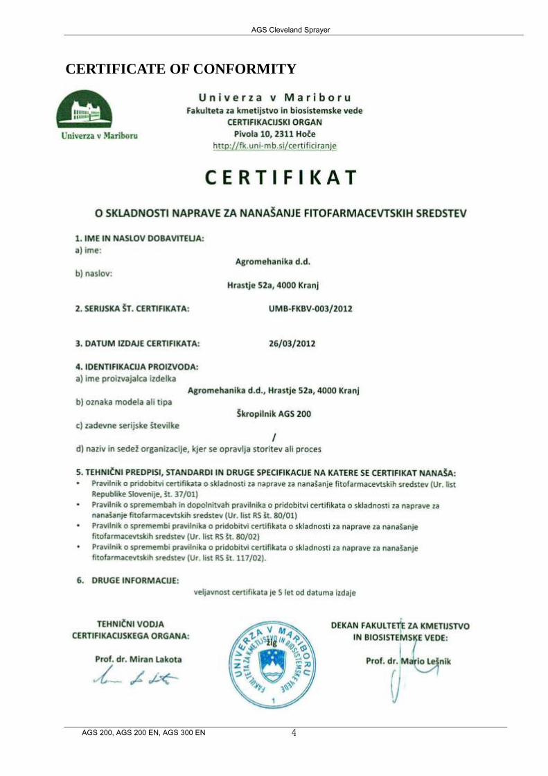
CERTIFICATE OF CONFORMITY
AGS Cleveland Sprayer
AGS 200, AGS 200 EN, AGS 300 EN 5
AGS Cleveland Sprayer
AGS 200, AGS 200 EN, AGS 300 EN 6

AGS Cleveland Sprayer
AGS 200, AGS 200 EN, AGS 300 EN 7
Dear customer, We would like to thank you for your trust, which you have shown by buying the sprayer appliance for chemical plant protection of the company AGROMEHANIKA. The reliability and efficiency of the appliance depends on how you will take care of the appliance. We advise you to read and consider this instruction manual carefully before connecting the appliance to the tractor. This manual contains essential information for efficient use and a long durability of the appliance.
1 IN GENERAL
Your spraying appliance has been designed and constructed for distributing of chemical agents in a water solution that are commonly used for chemical protection of agricultural cultures on the annual agrarian crops. The constructional design of the sprayer allows easy accessibility to the vital parts of the sprayer and even an easier handling. The strong construction, high-quality component parts and loads and loads of additional equipment ensures the user an efficient operation and an optimal consumption of insecticide and energy. Do not use your sprayer for pumping or spraying of:
- water solutions with a higher specific weight and viscosity than water; - chemical solutions which should not come in contact with some of the parts of the sprayer; - drinking water; - sea water and other salty solutions; - water which temperature is higher than 40 °C or lower than 5 °C; - all kinds of lacquer or varnish; - fast dissolving diluents; - oil or grease; - liquids that contain granulates or hard swimming parts.
2 INSTRUCTIONS FOR SAFE OPERATION AND SAFETY
WARNINGS
2.1 SAFETY MEASURES
The sign on the left is a safety warning sign. Take special care when you see this sign on your machine or in this instruction manual, since it is a matter of your safety. Follow the rules and instructions for a safe use which are listed bellow.
2.2 CONSIDERING THE SAFETY RULES
Read the instructions considering the safety rules in the operation manual of your machine very carefully. Make sure that the labels on the machine are in good condition and can be well seen. After repairing the machine or replacement of any spare part make sure that all of the labels are fitted on the appliance. Spare labels are available at your authorized seller of the appliances. Learn how your machine is working and how to handle it and its control units.
DO NOT ALLOW UNAUTHORIZED PEOPLE TO USE THE MACHINE!
Make sure that your machine is always in good working condition. Each unauthorized change on the machine can weaken the functionality and/or the safe operation and/or shorten the durability period of the appliance.
AGS Cleveland Sprayer
AGS 200, AGS 200 EN, AGS 300 EN 8
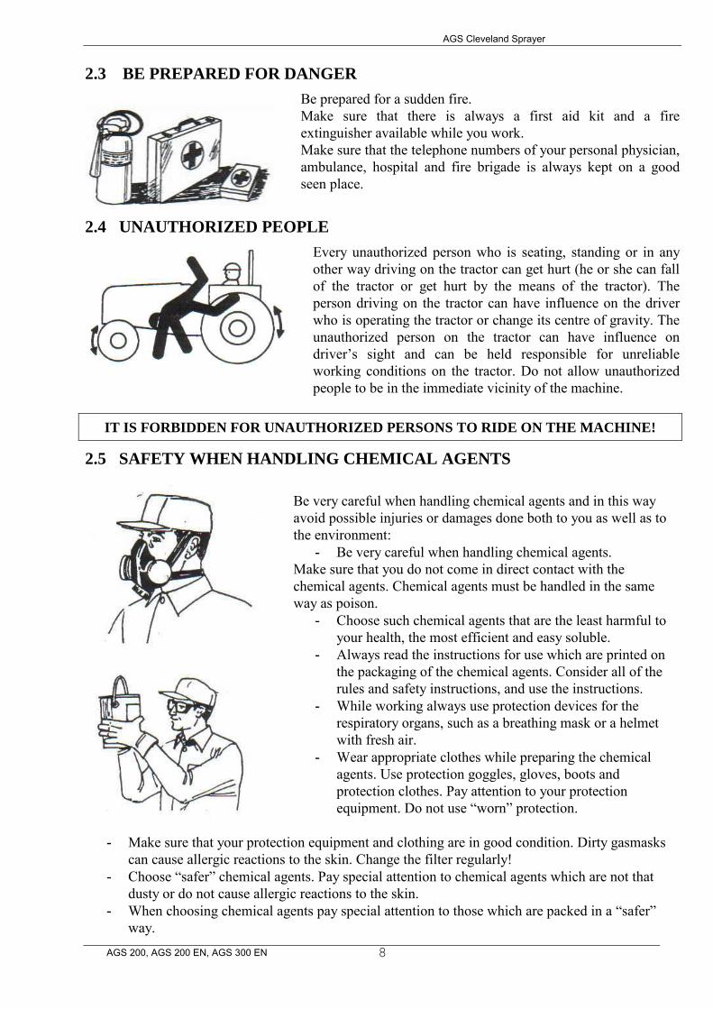
2.3 BE PREPARED FOR DANGER
Be prepared for a sudden fire. Make sure that there is always a first aid kit and a fire extinguisher available while you work. Make sure that the telephone numbers of your personal physician, ambulance, hospital and fire brigade is always kept on a good seen place.
2.4 UNAUTHORIZED PEOPLE
Every unauthorized person who is seating, standing or in any other way driving on the tractor can get hurt (he or she can fall of the tractor or get hurt by the means of the tractor). The person driving on the tractor can have influence on the driver who is operating the tractor or change its centre of gravity. The unauthorized person on the tractor can have influence on driver’s sight and can be held responsible for unreliable working conditions on the tractor. Do not allow unauthorized people to be in the immediate vicinity of the machine.
IT IS FORBIDDEN FOR UNAUTHORIZED PERSONS TO RIDE ON THE MACHINE!
2.5 SAFETY WHEN HANDLING CHEMICAL AGENTS
Be very careful when handling chemical agents and in this way avoid possible injuries or damages done both to you as well as to the environment:
- Be very careful when handling chemical agents. Make sure that you do not come in direct contact with the chemical agents. Chemical agents must be handled in the same way as poison.
- Choose such chemical agents that are the least harmful to your health, the most efficient and easy soluble.
- Always read the instructions for use which are printed on the packaging of the chemical agents. Consider all of the rules and safety instructions, and use the instructions.
- While working always use protection devices for the respiratory organs, such as a breathing mask or a helmet with fresh air.
- Wear appropriate clothes while preparing the chemical agents. Use protection goggles, gloves, boots and protection clothes. Pay attention to your protection equipment. Do not use “worn” protection.
- Make sure that your protection equipment and clothing are in good condition. Dirty gasmasks
can cause allergic reactions to the skin. Change the filter regularly! - Choose “safer” chemical agents. Pay special attention to chemical agents which are not that
dusty or do not cause allergic reactions to the skin. - When choosing chemical agents pay special attention to those which are packed in a “safer”
way.
AGS Cleveland Sprayer
AGS 200, AGS 200 EN, AGS 300 EN 9
The preparing of chemical agents should never take place in closed rooms. When you are preparing chemical agents turn off the machine and in this way lower the risk of spilling the chemical agent.
- The chemical agents should be prepared only in still weather or in a calm place. - Make sure that your machine is regularly cleaned, since you can in this way lower the chance of
a direct contact with the chemicals. - For preparing and mixing of the chemical agents only tools for this purpose should be used:
measuring scale, measuring tools, funnel, bucket. Make sure that the tools are cleaned regularly. - Do not prepare more of the chemical agents than needed. - Make sure that your working day in which you are using chemical agents is not longer than 8
hours. Avoid stress and heavy manual work. - Before spraying and 8 hours after spraying it is recommended not to consume alcohol. - Do not eat, drink or smoke while working with chemical agents. - Do not try to clean blocked nozzles with blowing (by means of your mouth). - Consider the abstinence of the insecticide in the spraying period. - Immediately wash out your eyes with water if the chemical comes in contact with them. - After spraying, wash your face and hands thoroughly before eating or drinking. - Make sure that children and animals cannot get to the machine until this one was thoroughly
cleaned. - Clean the machine after using it, put it in an appropriate place and make sure that unauthorized
people do not have access to it. - After using chemical agents wash yourself thoroughly. - Clean and wash the machine after every single use and before any maintenance work. - In case you have a certain medical problem in the time while using the chemical agents, consult
your personal physician and try to contact the selling agent who is responsible for your chemical agents.
- If you have an accident which involves a chemical agent, we advise you to do the following: - eyes and skin: wash with plenty of fresh water; - throat and gullet: drink loads of water (no milk!); - lungs: fresh air.
2.6 EVALUATION OF DANGER SIGNS ACCORDING TO DANGER
Each chemical agent has a danger sign printed on the packaging which conveys the degree of danger. If possible, avoid chemical agents which have a skull printed on the packaging or include other signs which say that certain chemical agents have an etching effect. Even if a packaging does not include signs of danger that does not mean that the chemical agents is not harmful or dangerous. Although you are using insecticides that have none of the danger signs printed on the packaging we advise you to handle them with extreme care, since they can be harmful to your health in the long term.
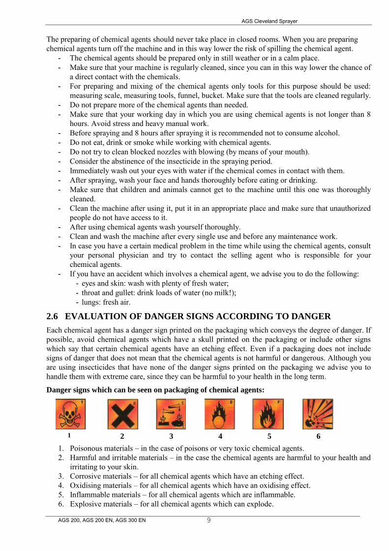
Danger signs which can be seen on packaging of chemical agents:
1 2 3 4 5 6
1. Poisonous materials – in the case of poisons or very toxic chemical agents. 2. Harmful and irritable materials – in the case the chemical agents are harmful to your health and
irritating to your skin. 3. Corrosive materials – for all chemical agents which have an etching effect. 4. Oxidising materials – for all chemical agents which have an oxidising effect. 5. Inflammable materials – for all chemical agents which are inflammable. 6. Explosive materials – for all chemical agents which can explode.
AGS Cleveland Sprayer
AGS 200, AGS 200 EN, AGS 300 EN
10
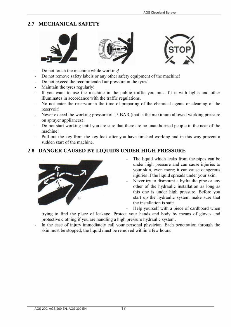
2.7 MECHANICAL SAFETY
- Do not touch the machine while working! - Do not remove safety labels or any other safety equipment of the machine! - Do not exceed the recommended air pressure in the tyres! - Maintain the tyres regularly! - If you want to use the machine in the public traffic you must fit it with lights and other
illuminates in accordance with the traffic regulations. - No not enter the reservoir in the time of preparing of the chemical agents or cleaning of the
reservoir! - Never exceed the working pressure of 15 BAR (that is the maximum allowed working pressure
on sprayer appliances)! - Do not start working until you are sure that there are no unauthorized people in the near of the
machine! - Pull out the key from the key-lock after you have finished working and in this way prevent a
sudden start of the machine.
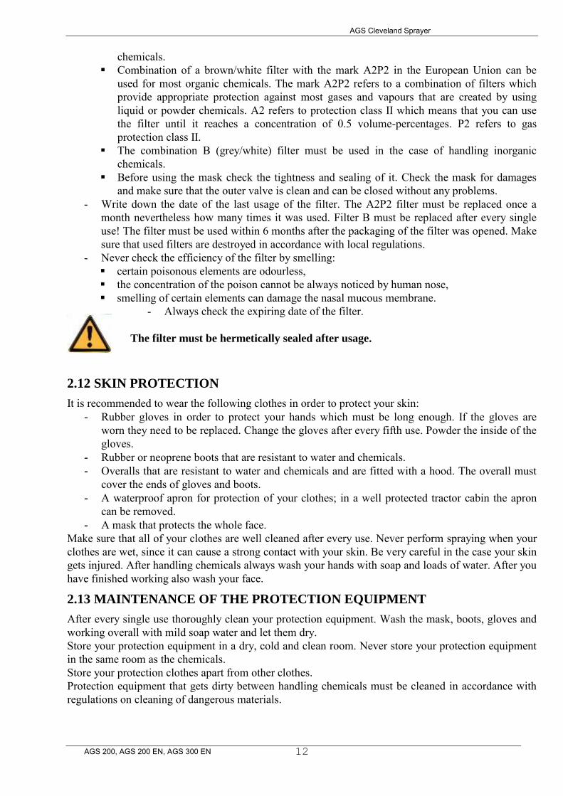
2.8 DANGER CAUSED BY LIQUIDS UNDER HIGH PRESSURE
- The liquid which leaks from the pipes can be under high pressure and can cause injuries to your skin, even more; it can cause dangerous injuries if the liquid spreads under your skin.
- Never try to dismount a hydraulic pipe or any other of the hydraulic installation as long as this one is under high pressure. Before you start up the hydraulic system make sure that the installation is safe.
- Help yourself with a piece of cardboard when trying to find the place of leakage. Protect your hands and body by means of gloves and protective clothing if you are handling a high pressure hydraulic system.
- In the case of injury immediately call your personal physician. Each penetration through the skin must be stopped; the liquid must be removed within a few hours.

AGS Cleveland Sprayer
AGS 200, AGS 200 EN, AGS 300 EN
11
2.9 WORKING PLACE OF THE MACHINE OPERATOR
- There is only one person needed for operation the machine. This person does not need an assistant. The operator of the sprayer is also the driver of the tractor.
- This machine can be operated by a person who is older than 18 years and has the needed know-how that is needed for a safe and accurate operation of spraying appliances.
- The person needs to be in good health – mentally and physically. - Operational work and maintaining of the sprayer can be only carried out by authorized personal
that has the needed know-how for this type of work. - The operator of the sprayer must have a medical certificate (in accordance with local
regulations). - The working place of the operator: 1 meter around the machine and tractor. - While spraying keep the windows and doors of the tractor closed. It is recommended that the
operator has a hermetically closed cabin which allows the operator to create overpressure with aeration of fresh air that disables chemically polluted air to enter the cabin.
- While spraying, it is recommended that the operator stays in the cabin for about 90-95% of the time, so the chemical agents cannot have influence on his or hers health. Should the operator notice a change in the working of his or hers organs or feel dizzy, he or she should immediately put on the protection breathing mask. However, the best thing to do is to leave the field and look for shelter in a cleaner area.
2.10 PERSONAL PROTECTION
- The operator is advised to use well buttoned clothing and efficient protection equipment while working.
- The operator can come in contact with chemicals through his or her skin, mouth or nose. If you do not work safely even the best protection equipment cannot be any use to you.
- A safe working with sprayers requires full attention of the operator, so listening to music (per headphones) while working is not recommended.
WARNING: To prevent inhaling and/or entering the chemicals through the
mouth it is recommended not to eat, drink or smoke while working!
2.11 BREATHING PROTECTION
There are many different types of filters available that can protect you against inhaling chemicals.
- It is recommended to use masks that protect the whole face and are fitted with combinations of different filters (filter for gas-smoke). An even more efficient protection can be achieved by means of a protection helmet in which overpressure can be created.
- Make sure that you are using an appropriate filter: A (brown): can be used for most organic chemicals. B (grey): can be used for most anorganic chemicals. P (white): can be used only for liquid or powder
AGS Cleveland Sprayer
AGS 200, AGS 200 EN, AGS 300 EN
12
chemicals. Combination of a brown/white filter with the mark A2P2 in the European Union can be
used for most organic chemicals. The mark A2P2 refers to a combination of filters which provide appropriate protection against most gases and vapours that are created by using liquid or powder chemicals. A2 refers to protection class II which means that you can use the filter until it reaches a concentration of 0.5 volume-percentages. P2 refers to gas protection class II.
The combination B (grey/white) filter must be used in the case of handling inorganic chemicals.
Before using the mask check the tightness and sealing of it. Check the mask for damages and make sure that the outer valve is clean and can be closed without any problems.
- Write down the date of the last usage of the filter. The A2P2 filter must be replaced once a month nevertheless how many times it was used. Filter B must be replaced after every single use! The filter must be used within 6 months after the packaging of the filter was opened. Make sure that used filters are destroyed in accordance with local regulations.
- Never check the efficiency of the filter by smelling: certain poisonous elements are odourless, the concentration of the poison cannot be always noticed by human nose, smelling of certain elements can damage the nasal mucous membrane.
- Always check the expiring date of the filter. The filter must be hermetically sealed after usage.
2.12 SKIN PROTECTION
It is recommended to wear the following clothes in order to protect your skin: - Rubber gloves in order to protect your hands which must be long enough. If the gloves are
worn they need to be replaced. Change the gloves after every fifth use. Powder the inside of the gloves.
- Rubber or neoprene boots that are resistant to water and chemicals. - Overalls that are resistant to water and chemicals and are fitted with a hood. The overall must
cover the ends of gloves and boots. - A waterproof apron for protection of your clothes; in a well protected tractor cabin the apron
can be removed. - A mask that protects the whole face.
Make sure that all of your clothes are well cleaned after every use. Never perform spraying when your clothes are wet, since it can cause a strong contact with your skin. Be very careful in the case your skin gets injured. After handling chemicals always wash your hands with soap and loads of water. After you have finished working also wash your face.
2.13 MAINTENANCE OF THE PROTECTION EQUIPMENT
After every single use thoroughly clean your protection equipment. Wash the mask, boots, gloves and working overall with mild soap water and let them dry. Store your protection equipment in a dry, cold and clean room. Never store your protection equipment in the same room as the chemicals. Store your protection clothes apart from other clothes. Protection equipment that gets dirty between handling chemicals must be cleaned in accordance with regulations on cleaning of dangerous materials.
AGS Cleveland Sprayer
AGS 200, AGS 200 EN, AGS 300 EN
13
2.14 SAFE OPERATION
Before starting working the operator must check the correct and safe operation of the machine. - It is not allowed to spray in foggy and/or rainy weather or when the wind speed exceeds 4 m/s. The
direction of spraying must be adjusted to the wind direction. - If there are two tractors with spraying appliances working simultaneously, they must not pollute
each others working area atmosphere. In order to protect your health pay attention to the wind direction and speed.
- Never bring personal things in the area of spraying or when handling chemicals. Before every meal thoroughly clean your hands and face and wash out your mouth with fresh water.
- Before filling in the chemicals check the functioning of the machine by filling the reservoir with clean water.
- The sprayer pump receives the power from the connecting shaft of the tractor by means of the cardan shaft. All of the driving parts can cause bad injuries so in order to avoid that please follow the instructions below: - To drive the pump only such a cardan shaft must be used which characteristics are in accordance
with the recommendations of the manufacturer and which is fitted with a protection cover. - Connect the machine to the tractor only if the drive shaft (P.T.O.) is turned off. - Connecting and disconnecting of the cardan shaft must be performed only when the engine is shut
off. - Before you load the drive shaft (P.T.O.) check the rpm of the engine and make sure that there are
no people or animals in the danger area of the machine. - The cardan shaft should be cleaned and greased only when the drive shaft (P.T.O.) is turned off, the
engine shut down and the start key out of the key-lock. - Do not turn on the drive shaft of the tractor (P.T.O.) without a reason and check if the difference
between the universal-joint angles is not too big.
Warning! Do not turn on the driving shaft of the tractor (P.T.O.) while the
tractor’s engine is not running!
2.15 SAFE MAINTENANCE
- Before starting to operate the machine learn how to maintain it. Keep the working place clean and dry. - Do not grease, maintain or adjust the machine while this is moving! Do not touch moving parts of the
machine! Turn off the machine and make sure that there is no working pressure in the circulation of the chemicals!
- Do not maintain or service the machine before this was thoroughly cleaned. - During maintenance and servicing of the machine turn off the electrical charging by turning the start
key or disconnecting the connections. - Disconnect the drive shaft of the tractor (P.T.O.) in order to avoid a sudden start of the sprayer. - Do not perform inspections of the machine without turning on the machine’s “safety” devices. - Do not perform welding of the machine if you have used ammonium nitrate or any other liquid that
contains ammonium nitrate for spraying without having thoroughly cleaned the machine before. - Do not enter the reservoir to repair or clean it. - Support and safely mount all parts that need to be lifted during maintenance. - Keep all of the sprayer’s parts in good condition. Repair eventual damages immediately. Replace worn
and damaged parts. Remove excess oil, grease or any other debris. - Disconnect the battery before you start to adjust the electrical system or perform welding on the
machine. - During maintenance of the machine or cleaning the nozzles use appropriate protection equipment in
accordance with the regulations. - It is strictly forbidden to release chemicals into the environment.

AGS Cleveland Sprayer
AGS 200, AGS 200 EN, AGS 300 EN
14
2.16 DRIVING ALONG ROADS AND STREETS
Do not drive around with your sprayer attached to the tractor. If this can not be avoided please consider the following: - Drive along roads and streets with your sprayer attached to the tractor only when there are no
chemical agents in the reservoir. The maximum tractor speed with a full reservoir of water must not exceed 15 km/h.
- Connect the sprayer to the tractor only if the load on the wheels does not exceed the prescribed maximal load. After connecting the sprayer to the tractor at least 25% of weight must be on front wheels. You can achieve these values by adding weights at the front and removing weights at the back of the tractor. Find out how many weights need to be added or removed by means of weighing the tractor before the first use of the sprayer.
- In the case the sprayer completely or partially covers the lights and signs at the back of the tractor you will have to attach some additional lights and signs onto the sprayer.
- Follow the traffic regulations when driving along roads and streets with your sprayer attached to the tractor.
- Keep the boom on an appropriate height when driving along roads and streets. In the upper position secure the 3-point suspension of the tractor in order to avoid a sudden fall or slip of the sprayer as well as its lateral oscillation.
2.17 PROCEDURES IN THE CASE OF ACCIDENTS WITH CHEMICALS
In the case your skin or eyes come in contact with chemicals or their solution, wash them out with plenty of water and repeat the process several times. In the case of suspecting poisoning (symptoms: sweating, dizziness, depression, headache, sickness): - immediately stop working; - take off wet clothes; - remain calm; - if you feel sick because of consumption of chemicals try to throw up; - lay on your side; - immediately call for medical help and let the physician see the label of the chemical agent, so he or
she will easier be able to determine the kind of poisoning. In the case of suspecting poisoning the patient must not eat or drink castor oil, milk, butter, eggs and alcohol, since these ingredients worsen the poisoning effect.
2.18 RULES REGARDING TO USE OF SPRAYING APPLIANCES
The operator and user of the SPRAYER must be familiar with rules regarding plant protection.
AGS Cleveland Sprayer
AGS 200, AGS 200 EN, AGS 300 EN
15
3 LABELS WITH SAFETY PRECAUTIONS AND INSTRUCTIONS
FOR USE
You can find certain safety and warning signs in this instruction manual that are also attached to the machine. Take a closer look at them in order to work safely. Follow the instructions and advice concerning precautions listed in the previous chapter. Make sure that the labels on the machine are in good condition and can be well seen. After repairing the machine or replacement of any spare part make sure that all of the labels are fitted on the appliance. Spare labels are available at your authorized seller of the appliances.
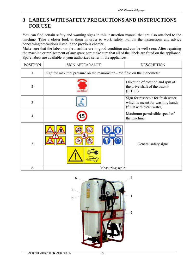
POSITION SIGN APPEARANCE DESCRIPTION
1 Sign for maximal pressure on the manometer – red field on the manometer
2
Direction of rotation and rpm of the drive shaft of the tractor (P.T.O.)
3 Sign for reservoir for fresh water
which is meant for washing hands (fill it with clean water)
4 Maximum permissible speed of
the machine
5
General safety signs
6 Measuring scale

AGS Cleveland Sprayer
AGS 200, AGS 200 EN, AGS 300 EN
16
Learn how to operate the machine well and never allow people to operate the machine who are not familiar with the instructions manual. The table below contains descriptions of different safety signs.
CE statement of conformity
Warning! Presence of poisonous chemical agents!
Warning! Sign that indicates the possibility of personal injuries or damages of the machine!
Warning! Maximal allowed pressure in the spraying appliance (12 bar)
Warning! Keep away from rotating drive shafts!
Warning! Direction of rotation of the drive shaft
Warning! Read the instruction manual before connecting the appliance to the tractor for the first time!
It is not allowed to clean, grease or maintain the appliance as long as it is running!
Unauthorized persons are not allowed to enter into the working area of the machine!
It is not allowed to smoke
while operating the appliance!
It is not allowed to remove any of the safety devices from the machine!
It is not allowed to enter the reservoir!
Recommendation! Read the instructions for use!
Recommendation! If the cabin of the tractor is not constructed in an appropriate way, use your gas mask while working.
Recommendation! Use protective gloves while working!
Recommendation! Use protection overalls while working!
Recommendation! Use ear protectors while working (only applies to sprayers)!
Water for washing of hands. Warning: this water is not
drinkable!

AGS Cleveland Sprayer
AGS 200, AGS 200 EN, AGS 300 EN
17
4 DESCRIPTION
Sprayers type AGS 200, AGS 200EN, AGS 300EN and AGS 400EN/L have a modern design with a thin polyethylene reservoir with rounded edges, smooth inner walls and a sloping bottom. The construction assures a short centre of gravity between the tractor and the sprayer, good insecticide mixing, easy cleaning and complete emptying of the reservoir. The sprayer consists of: - a carrying frame with a polyethylene reservoir and a pouring sieve which are resistant to chemicals; - a pump; - a flow and pressure regulator; - a suction filter; - a pressure filter and - three-way valves. The standard equipment of sprayers type AGS 200EN, AGS 300EN and AGS 400EN/L also includes an additional reservoir for cleaning of the sprayer after finished working and a reservoir for clean water which is meant for washing of hands. Standard spraying booms of 6m, 8m, 10m and 12m can be connected to all types of sprayers (a spraying garniter of up to 8 m of working width is recommended for sprayer types AGS 200 and AGS 200EN). The following instructions include detailed information on sprayer’s component parts and how to handle them; the second part of this manual includes a catalogue of spare parts. Since this manual includes information on all sprayer models only pay attention to those parts that refer to your model.
4.1 LIFTING POINTS
When loading or unloading the sprayer onto or from the truck, use the standard lifting points of the three-point lifting system or, when this is not possible, the bottom of the sprayer (in case of using a fork lift).
4.2 COMPONENTS OF THE SPRAYER
1. frame 2. suction filter 3. three-way valve 4. pump 5. main reservoir 6. ablution reservoir 7. clean water reservoir 8. level indicator
9. pressure regulator 10. manometer 11. selection valve 12. three-way valve with a release 13. cover with a pouring sieve 14. identification plate 15. spraying boom
AGS Cleveland Sprayer
AGS 200, AGS 200 EN, AGS 300 EN
18
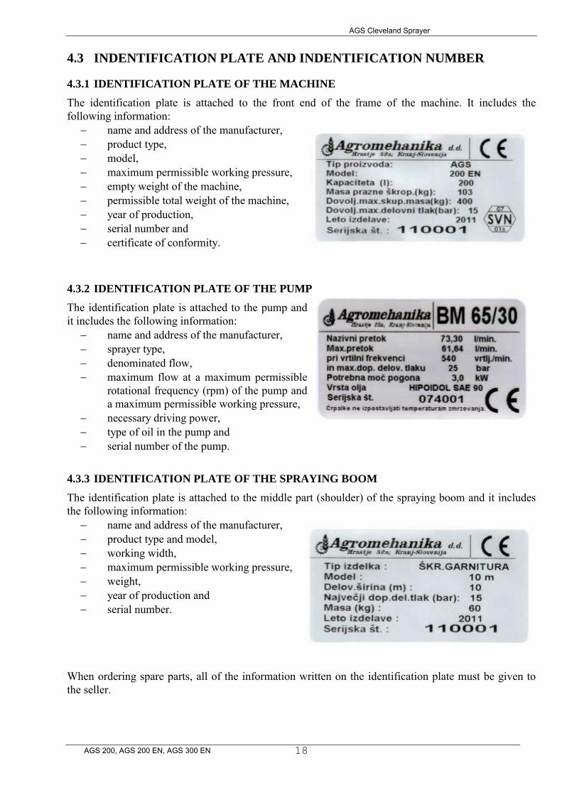
4.3 INDENTIFICATION PLATE AND INDENTIFICATION NUMBER
4.3.1 IDENTIFICATION PLATE OF THE MACHINE
The identification plate is attached to the front end of the frame of the machine. It includes the following information:
name and address of the manufacturer, product type, model, maximum permissible working pressure, empty weight of the machine, permissible total weight of the machine, year of production, serial number and certificate of conformity.
4.3.2 IDENTIFICATION PLATE OF THE PUMP
The identification plate is attached to the pump and it includes the following information:
name and address of the manufacturer, sprayer type, denominated flow, maximum flow at a maximum permissible
rotational frequency (rpm) of the pump and a maximum permissible working pressure,
necessary driving power, type of oil in the pump and serial number of the pump.
4.3.3 IDENTIFICATION PLATE OF THE SPRAYING BOOM
The identification plate is attached to the middle part (shoulder) of the spraying boom and it includes the following information:
name and address of the manufacturer, product type and model, working width, maximum permissible working pressure, weight, year of production and serial number.
When ordering spare parts, all of the information written on the identification plate must be given to the seller.

AGS Cleveland Sprayer
AGS 200, AGS 200 EN, AGS 300 EN
19
4.4 FUNCTION SCHEME (AGS 200EN, AGS 300EN, AGS 400EN/L)
1. Three-way valve with release on EN version /3 position filter unit on AGS 200,350,4502. Three-way selection valve N/A on AGS 200,350,4503. Suction filter /Included in 1 on AGS 200, 350,4504. Pump 5. Pressure regulator 6. Mixing nozzle feeding valve 7. Valves that open individual sections for spraying 8. Main sprayer tank 9. Selection valve N/A on AGS 200,350,450 10. Ablution reservoir N/A on AGS 200,350,45011. Clean water reservoir (to wash hands) mounted to sprayer frame on AGS 200,350,45012. Pouring sieve 13. Nozzles 14. Mixing nozzle 15. Manometer /Pressure gauge16. Nozzle for tank wash N/A on AGS 200,350,450
AGS Cleveland Sprayer
AGS 200, AGS 200 EN, AGS 300 EN
20
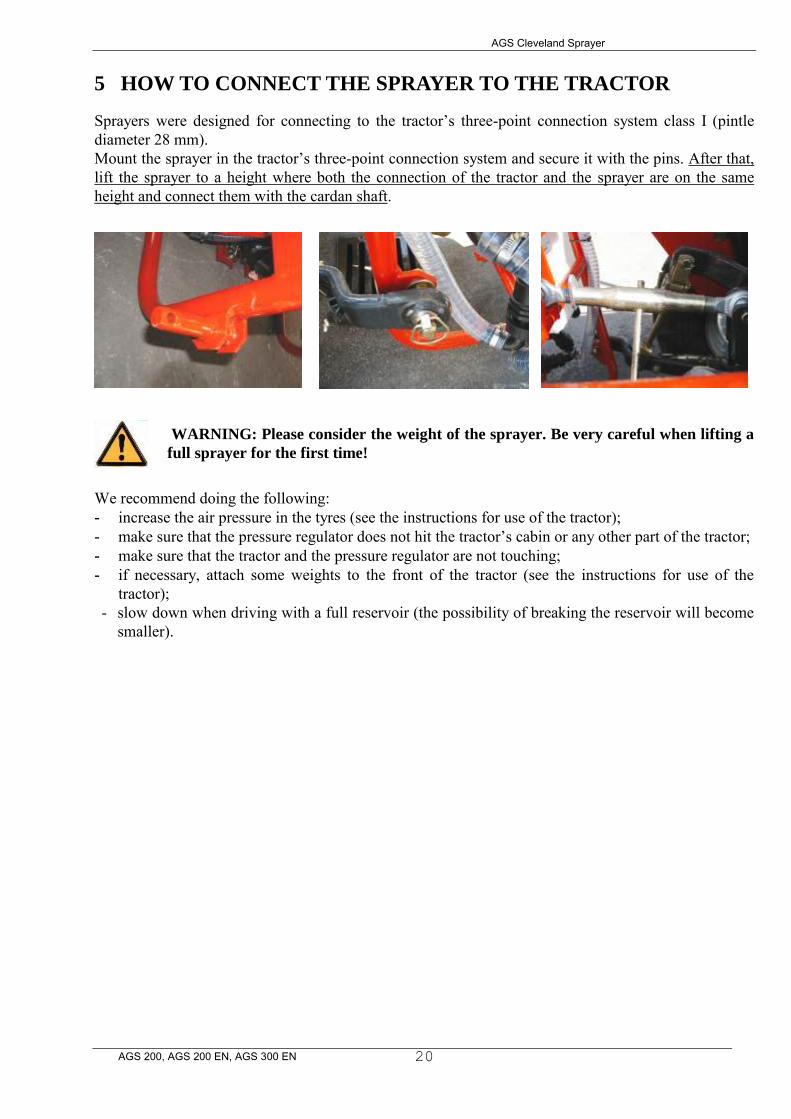
5 HOW TO CONNECT THE SPRAYER TO THE TRACTOR
Sprayers were designed for connecting to the tractor’s three-point connection system class I (pintle diameter 28 mm). Mount the sprayer in the tractor’s three-point connection system and secure it with the pins. After that, lift the sprayer to a height where both the connection of the tractor and the sprayer are on the same height and connect them with the cardan shaft.
WARNING: Please consider the weight of the sprayer. Be very careful when lifting a
full sprayer for the first time!
We recommend doing the following: - increase the air pressure in the tyres (see the instructions for use of the tractor); - make sure that the pressure regulator does not hit the tractor’s cabin or any other part of the tractor; - make sure that the tractor and the pressure regulator are not touching; - if necessary, attach some weights to the front of the tractor (see the instructions for use of the
tractor); - slow down when driving with a full reservoir (the possibility of breaking the reservoir will become
smaller).
AGS Cleveland Sprayer
AGS 200, AGS 200 EN, AGS 300 EN
21
6 MOUNTING OF THE DRIVE SHAFT (CARDAN SHAFT)
6.1 OPERATOR’S SAFETY
To avoid possible accidents and personal injuries please follow the instructions and recommendations written below:
- Before mounting (connecting of the cardan shaft to the tractor and the sprayer) the drive shaft – cardan shaft, always turn off the engine and remove the start key from its lock. When mounting the cardan shaft, the cardan shaft of the tractor can be easily turned if the engine and the cardan shaft are turned off.
- When mounting the cardan shaft make sure that the safety pin is in right position and well stuck in its hole. Pull and push the cardan shaft forwards and backwards as long as the safety pin is not in its hole.
- Rotating shafts can be very dangerous! - Always make sure that all of the safety devices are on their place and that all of the rotating
surfaces are well covered, including the “junctions” of the cardan shaft on both ends! Do not use cardan shafts without having secured them!
- Do not touch rotating cardan shafts! The safety distance to a rotating cardan should not be less than 1.5 m.
- Protect the protection devices against turning by means of the chain! - Make sure that the protection of the cardan on the tractor is well connected (attached)! - Always turn off the engine and remove the start key from its lock before starting maintaining the
machine or connecting the cardan shaft!
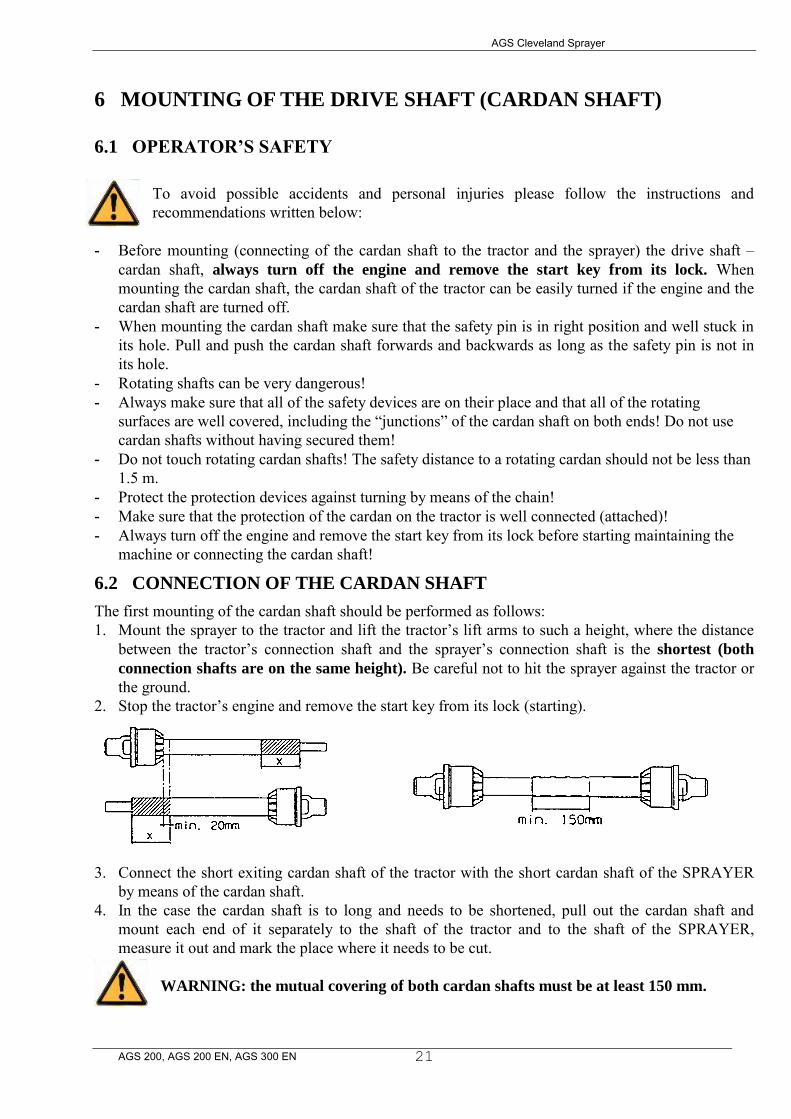
6.2 CONNECTION OF THE CARDAN SHAFT
The first mounting of the cardan shaft should be performed as follows: 1. Mount the sprayer to the tractor and lift the tractor’s lift arms to such a height, where the distance
between the tractor’s connection shaft and the sprayer’s connection shaft is the shortest (both
connection shafts are on the same height). Be careful not to hit the sprayer against the tractor or the ground.
2. Stop the tractor’s engine and remove the start key from its lock (starting).
3. Connect the short exiting cardan shaft of the tractor with the short cardan shaft of the SPRAYER by means of the cardan shaft.
4. In the case the cardan shaft is to long and needs to be shortened, pull out the cardan shaft and mount each end of it separately to the shaft of the tractor and to the shaft of the SPRAYER, measure it out and mark the place where it needs to be cut.
WARNING: the mutual covering of both cardan shafts must be at least 150 mm.

AGS Cleveland Sprayer
AGS 200, AGS 200 EN, AGS 300 EN
22
5. Use an appropriate tool to shorten both parts in the same way and do not forget to remove the swarf.
6. Attach the profiles and join both parts of the cardan shaft.
7. Mount the cardan shaft to the tractor and the sprayer.
WARNING: Always mount the female end of the cardan
shaft to the tractor! Connect the chains in order to avoid
rotating of the safety covers!
8. To assure a long reliability of the cardan shaft avoid angles
bigger than 15° (picture 8.4). 9. When using safety cardan shafts, the so called “ALLEN’S” bolt
must be screwed in with a torque of 40 Nm. Check the torque after two (2) minutes of operation.
7 DETAILED DESCRIPTION WITH INSTRUCTIONS FOR USE
The frame is made of a steel welded construction which comprises a reservoir, a pump that is attached to the lower part of the frame, a suction filter and valves for flow regulation. The pressure regulator is attached to the front of the construction, the lifting mechanism to which the spraying boom is attached to, is located in the back. Both the ablution reservoir and the clean water reservoir are fitted above the main reservoir.
7.1 MAIN RESERVOIR
The main reservoir is made of polyethylene which is resistant to chemicals. It has rounded edges and smooth inner walls for easier cleaning. The reservoir has a sloping bottom which assures a complete emptying of it. There is a sieve with cover mounted on the top of the reservoir. Do not remove the sieve while filling the reservoir with insecticide or water!
WARNING: Use protective gloves when handling insecticides!
A measuring scale is printed on the front side of the reservoir which facilitates the determination of the chemical agent. On the inside of the reservoir, a tube with a red PE ball inside is mounted for easier visual reading of the quantity of the chemical agent inside the reservoir.

AGS Cleveland Sprayer
AGS 200, AGS 200 EN, AGS 300 EN
23
7.1.1 RESERVOIR COVER AGS 200,350 & 450A single piece cover with a size of Ø230 mm has a breather fitted into the hole on the top.The cover can be opened by turning it to the left and closed by turning it to the right. While operating the machine, the cover must remain closed.
7.1.2 RESERVOIR COVER AGS 200EN, AGS 300EN, AGS 400EN/L
The cover consists of two parts. The smaller in the middle of the reservoir is meant for easier filling of water. It is recommended to use clean water. The cover can be opened by turning it to the left and closed by turning it to the right. While operating the machine, the cover must remain closed.
If the cover on your reservoir is similar to that displayed on the picture below, never put the hose through the opening in the top into the reservoir or do not allow the hose to touch the insecticide, since it can get contaminated! The pressure in the hose can drop and suck in some of the insecticide.
This also applies to the cover of a sprayer type AGS 200.
7.2 ABLUTION RESERVOIR (AGS 200EN, AGS 300EN, AGS 400EN/L)
The ablution reservoir is meant for washing of the reservoir and other elements after you have finished working or after a break. Fill the reservoir with clean water. You can find more detailed instructions in the chapter "DESCRIPTION OF VALVE ADJUSTMENT FOR SPRAYING OR CLEANING".
7.3 RESERVOIR FOR WASHING OF HANDS (AGS 200EN, AGS 300EN, AGS
400EN/L)
This reservoir is meant for washing of hands after handling insecticides. Fill the reservoir with drinkable water. Its capacity is 12.5 litres.
The water is not drinkable!
AGS Cleveland Sprayer
AGS 200, AGS 200 EN, AGS 300 EN
24
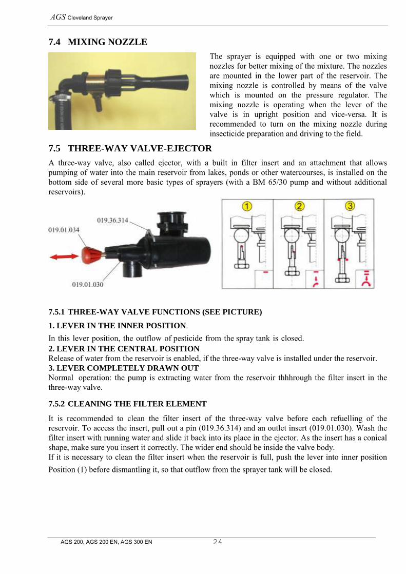
7.4 MIXING NOZZLE
The sprayer is equipped with one or two mixing nozzles for better mixing of the mixture. The nozzles are mounted in the lower part of the reservoir. The mixing nozzle is controlled by means of the valve which is mounted on the pressure regulator. The mixing nozzle is operating when the lever of the valve is in upright position and vice-versa. It is recommended to turn on the mixing nozzle during insecticide preparation and driving to the field.
7.5 THREE-WAY VALVE-EJECTOR
A three-way valve, also called ejector, with a built in filter insert and an attachment that allows pumping of water into the main reservoir from lakes, ponds or other watercourses, is installed on the bottom side of several more basic types of sprayers (with a BM 65/30 pump and without additional reservoirs).
7.5.1 THREE-WAY VALVE FUNCTIONS (SEE PICTURE)
1. LEVER IN THE INNER POSITION. In this lever position, the outflow of pesticide from the spray tank is closed. 2. LEVER IN THE CENTRAL POSITION
Release of water from the reservoir is enabled, if the three-way valve is installed under the reservoir. 3. LEVER COMPLETELY DRAWN OUT
Normal operation: the pump is extracting water from the reservoir thhhrough the filter insert in the three-way valve.
7.5.2 CLEANING THE FILTER ELEMENT
It is recommended to clean the filter insert of the three-way valve before each refuelling of the reservoir. To access the insert, pull out a pin (019.36.314) and an outlet insert (019.01.030). Wash the filter insert with running water and slide it back into its place in the ejector. As the insert has a conical shape, make sure you insert it correctly. The wider end should be inside the valve body. If it is necessary to clean the filter insert when the reservoir is full, push the lever into inner position Position (1) before dismantling it, so that outflow from the sprayer tank will be closed.
AGS Cleveland Sprayer
AGS 200, AGS 200 EN, AGS 300 EN
31
9 FLOW REGULATOR
9.1 THE FLOW REGULATOR PR3
The flow regulator PR-3 is meant for precise regulation of the working pressure from 0-12 bars. The basic version of the flow regulator PR-3C consists of a regulation valve, a central valve with vacuum anti-dripping system and direction control valves. The improved version PR-3B has direction-control-regulating valves mounted instead of direction control valves, which enables you to precisely set the operating pressure in individual sections of the spraying boom. The regulator is also equipped with a self-cleaning pressure filter.
9.1.1 REGULATOR MARKING
The basic marking PR-3C and PR-3B can be given an additional letter F which stands for the self-cleaning pressure filter. The number of direction-control-regulating valves and direction control valves is marked with a numeric code (the first number marks direction-control-regulating valves and the second marks direction control valves). For example:
The marking PR-3BF/5+1 stands for the regulator PR-3B with the self-cleaning pressure filter, five direction-control-regulating valves and one direction control valve.
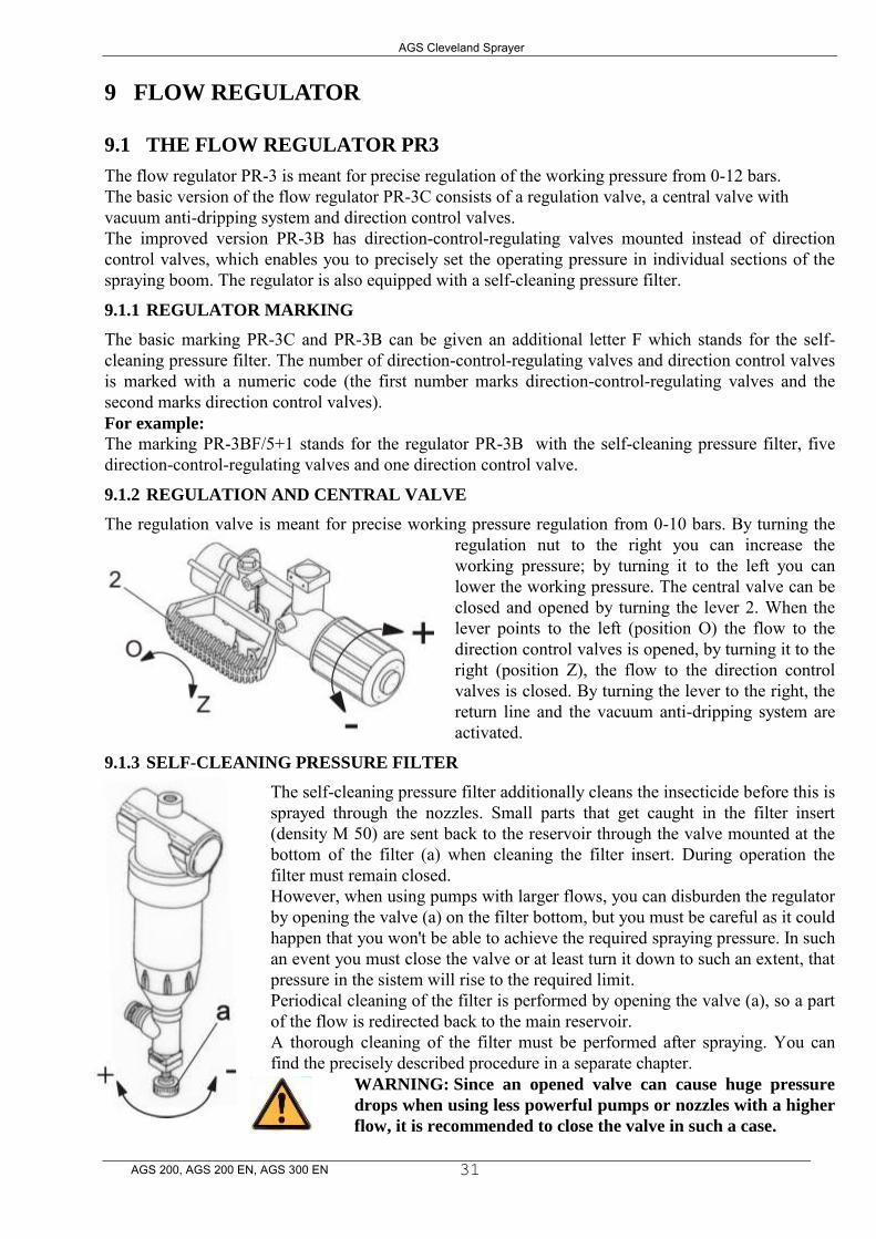
9.1.2 REGULATION AND CENTRAL VALVE
The regulation valve is meant for precise working pressure regulation from 0-10 bars. By turning the regulation nut to the right you can increase the working pressure; by turning it to the left you can lower the working pressure. The central valve can be closed and opened by turning the lever 2. When the lever points to the left (position O) the flow to the direction control valves is opened, by turning it to the right (position Z), the flow to the direction control valves is closed. By turning the lever to the right, the return line and the vacuum anti-dripping system are activated.
9.1.3 SELF-CLEANING PRESSURE FILTER
The self-cleaning pressure filter additionally cleans the insecticide before this is sprayed through the nozzles. Small parts that get caught in the filter insert (density M 50) are sent back to the reservoir through the valve mounted at the bottom of the filter (a) when cleaning the filter insert. During operation the filter must remain closed. However, when using pumps with larger flows, you can disburden the regulator by opening the valve (a) on the filter bottom, but you must be careful as it could happen that you won't be able to achieve the required spraying pressure. In such an event you must close the valve or at least turn it down to such an extent, that pressure in the sistem will rise to the required limit. Periodical cleaning of the filter is performed by opening the valve (a), so a part of the flow is redirected back to the main reservoir. A thorough cleaning of the filter must be performed after spraying. You can find the precisely described procedure in a separate chapter.
WARNING: Since an opened valve can cause huge pressure
drops when using less powerful pumps or nozzles with a higher
flow, it is recommended to close the valve in such a case.
AGS Cleveland Sprayer
AGS 200, AGS 200 EN, AGS 300 EN
32
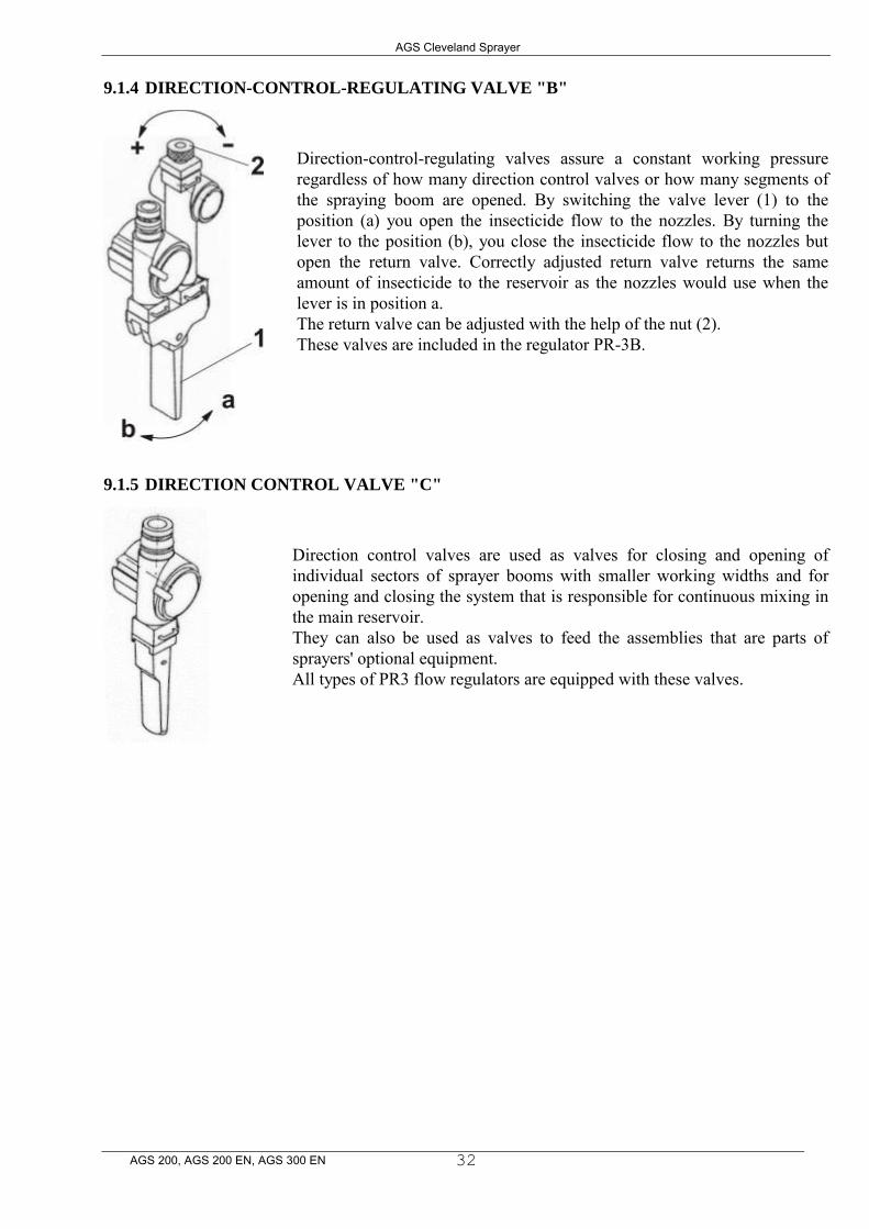
9.1.4 DIRECTION-CONTROL-REGULATING VALVE "B"
Direction-control-regulating valves assure a constant working pressure regardless of how many direction control valves or how many segments of the spraying boom are opened. By switching the valve lever (1) to the position (a) you open the insecticide flow to the nozzles. By turning the lever to the position (b), you close the insecticide flow to the nozzles but open the return valve. Correctly adjusted return valve returns the same amount of insecticide to the reservoir as the nozzles would use when the lever is in position a. The return valve can be adjusted with the help of the nut (2). These valves are included in the regulator PR-3B.
9.1.5 DIRECTION CONTROL VALVE "C"
Direction control valves are used as valves for closing and opening of individual sectors of sprayer booms with smaller working widths and for opening and closing the system that is responsible for continuous mixing in the main reservoir. They can also be used as valves to feed the assemblies that are parts of sprayers' optional equipment. All types of PR3 flow regulators are equipped with these valves.
AGS Cleveland Sprayer
AGS 200, AGS 200 EN, AGS 300 EN
33
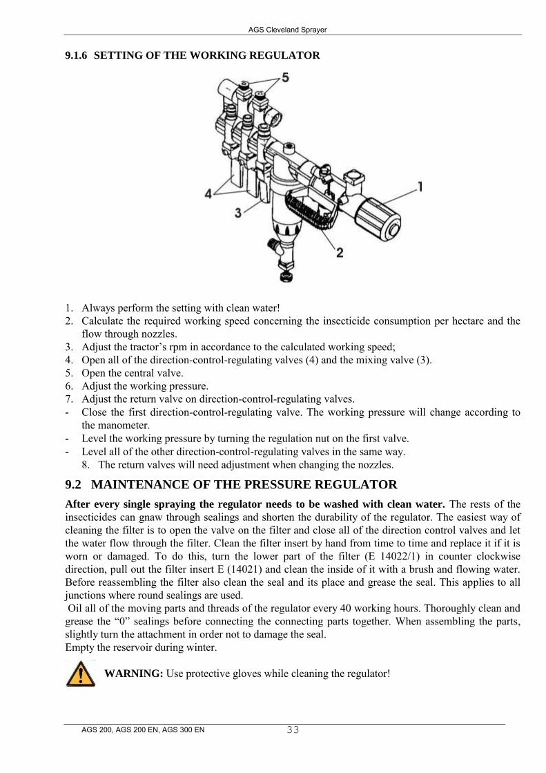
9.1.6 SETTING OF THE WORKING REGULATOR
1. Always perform the setting with clean water! 2. Calculate the required working speed concerning the insecticide consumption per hectare and the
flow through nozzles. 3. Adjust the tractor’s rpm in accordance to the calculated working speed; 4. Open all of the direction-control-regulating valves (4) and the mixing valve (3). 5. Open the central valve. 6. Adjust the working pressure. 7. Adjust the return valve on direction-control-regulating valves. - Close the first direction-control-regulating valve. The working pressure will change according to
the manometer. - Level the working pressure by turning the regulation nut on the first valve. - Level all of the other direction-control-regulating valves in the same way.
8. The return valves will need adjustment when changing the nozzles.
9.2 MAINTENANCE OF THE PRESSURE REGULATOR
After every single spraying the regulator needs to be washed with clean water. The rests of the insecticides can gnaw through sealings and shorten the durability of the regulator. The easiest way of cleaning the filter is to open the valve on the filter and close all of the direction control valves and let the water flow through the filter. Clean the filter insert by hand from time to time and replace it if it is worn or damaged. To do this, turn the lower part of the filter (E 14022/1) in counter clockwise direction, pull out the filter insert E (14021) and clean the inside of it with a brush and flowing water. Before reassembling the filter also clean the seal and its place and grease the seal. This applies to all junctions where round sealings are used. Oil all of the moving parts and threads of the regulator every 40 working hours. Thoroughly clean and grease the “0” sealings before connecting the connecting parts together. When assembling the parts, slightly turn the attachment in order not to damage the seal. Empty the reservoir during winter.
WARNING: Use protective gloves while cleaning the regulator!

AGS Cleveland Sprayer
AGS 200, AGS 200 EN, AGS 300 EN
34
10 PUMPS
Pumps are a vital element of spraying appliances. The reliability and a long durability of the pump also depend on how you treat the pump and whether you use and maintain it correctly. IMPORTANT: The standard version of all pumps is equipped with membranes which are made of NBR rubber. Therefore it is the user’s duty to use only chemical agents for spraying which do not harm this kind of material. On the opposite, the manufacturer can not be held responsible for any kind of damage that could occur.
10.1 CHECK BEFORE USING THE APPLIANCE
When the pump is not operating check the oil quantity in the housing of the pump. Also check the oil level every single time before filling the reservoir. The level must be within the limits which are marked on the oil lid or in the oil pot (depends on the version of the pump). If the oil level is too low add some oil whereas be careful not to exceed the maximum allowed level.
The air pressure in the air chamber depends on the working pressure which can be found in the diagram on the left. The air pressure in the air chamber must never be higher than the working pressure of the pump.
Make sure that the valves ensure free flow of liquid from the reservoir to the pump. Also check the porousness of the suction filter insert and the suction hose (make sure that the hose is not folded).
10.2 USE
Before turning on the pump make sure that the main valve is switched to position “Z” (see chapter “REGULATION AND CENTRAL VALVES”). Never turn on the pump’s drive when the setting on the regulator enables full stressing of the
pump. Turn on the pump and let it run for approximately one minute under minimum pressure in order to aerate the pump and the inlet and the outlet pipes. After one minute the pump is ready for operation. Be careful not to exceed the maximum allowed pressure and the maximum allowed rpm of 540. On the opposite, the manufacturer can not be held responsible for any kind of damage that could occur.
10.3 AFTER USE
Some chemical agents can shorten the durability of some vital parts of the pump such as rubber membranes and/or other rubber sealings. Therefore a thorough washing of the pump after every single spraying is recommended. To do this, you will need to pump some clean water through the pump. Let the pump operate at working pressure for several minutes. Lower the pressure and let the pump operate for approximately one minute to blow out the rest of the liquid (blowing out the pump). During winter, leave all of the water out of the pump and/or protect the pump against freezing (see chapter “MAINTENANCE AND STORAGE AFTER USE”).
AGS Cleveland Sprayer
AGS 200, AGS 200 EN, AGS 300 EN
35
10.4 PISTON MEMBRANE PUMPS BM 40/25, BM65/30 AND BM 105/20
Type BM 40/25, BM 65/30 BM105/20 pumps are low-pressure piston membrane pumps, made of materials that have been tested by the factory. The pumps are suitable for pumping of insecticides or liquid fertilizers which are used in farming.
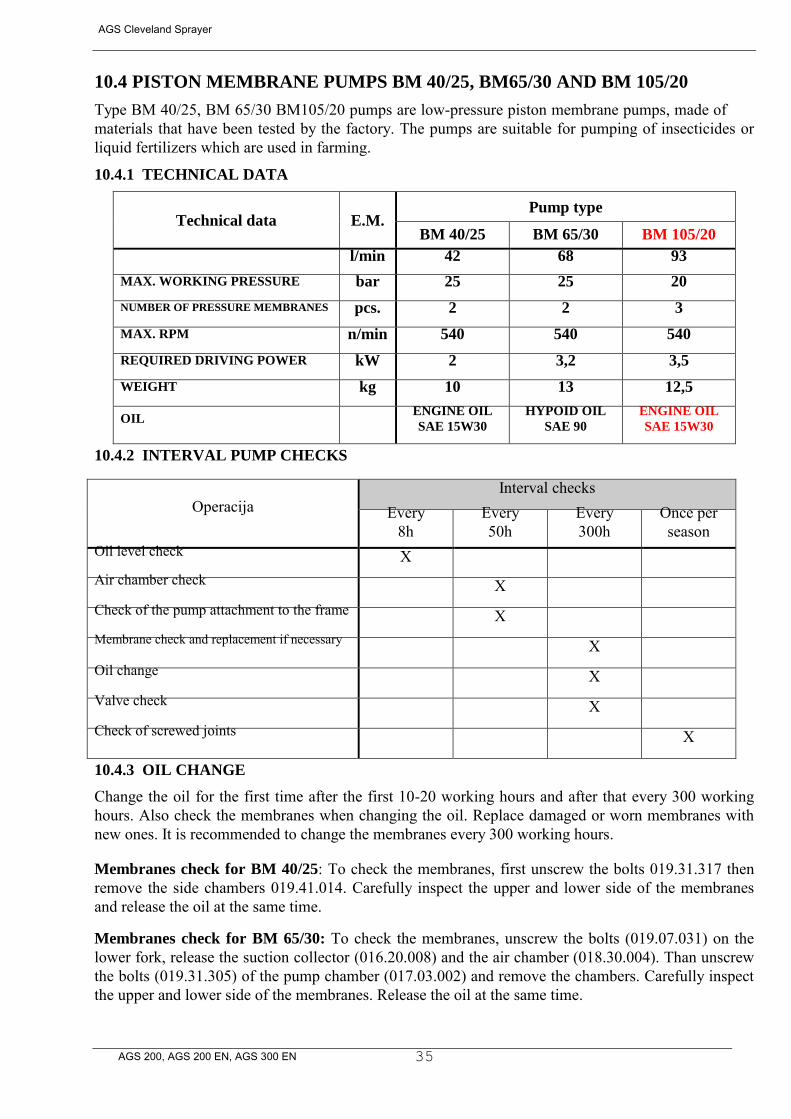
10.4.1 TECHNICAL DATA
Technical data E.M. Pump type
BM 40/25 BM 65/30 BM 105/20
l/min 42 68 93
MAX. WORKING PRESSURE bar 25 25 20
NUMBER OF PRESSURE MEMBRANES pcs. 2 2 3
MAX. RPM n/min 540 540 540
REQUIRED DRIVING POWER kW 2 3,2 3,5
WEIGHT kg 10 13 12,5
OIL ENGINE OIL
SAE 15W30 HYPOID OIL
SAE 90 ENGINE OIL
SAE 15W30
10.4.2 INTERVAL PUMP CHECKS
Operacija Interval checks
Every 8h
Every 50h
Every 300h
Once per season
Oil level check X Air chamber check X Check of the pump attachment to the frame X Membrane check and replacement if necessary X Oil change X Valve check X Check of screwed joints X
10.4.3 OIL CHANGE
Change the oil for the first time after the first 10-20 working hours and after that every 300 working hours. Also check the membranes when changing the oil. Replace damaged or worn membranes with new ones. It is recommended to change the membranes every 300 working hours. Membranes check for BM 40/25: To check the membranes, first unscrew the bolts 019.31.317 then remove the side chambers 019.41.014. Carefully inspect the upper and lower side of the membranes and release the oil at the same time.
Membranes check for BM 65/30: To check the membranes, unscrew the bolts (019.07.031) on the lower fork, release the suction collector (016.20.008) and the air chamber (018.30.004). Than unscrew the bolts (019.31.305) of the pump chamber (017.03.002) and remove the chambers. Carefully inspect the upper and lower side of the membranes. Release the oil at the same time.
AGS Cleveland Sprayer
AGS 200, AGS 200 EN, AGS 300 EN
36
Membranes check for BM 105/20: To check the membranes, first of all unscrew the bolts (540015) on the covers of the pump 017.41.007 and release the suction and pressure collector. After that, unscrew the bolts 019.31.317 on the covers 017.41.007 and remove the chambers. Carefully inspect the upper and lower side of the membranes. Release the oil at the same time.
WARNING: Make sure that the worn oil is poured into appropriate tanks! Do not discard worn oil in nature!
It is recommended to clean the inside of the pump and its vital parts with diesel oil before reassembling the pump. Assemble the pump in the opposite direction. Be careful to correctly insert the valves (see the catalogue). After that, pour fresh oil into the pump. For pumps type BM 40/25 and BM 65/30 oil needs to be poured in through the hole of the oil lid (019.01.101). For pumps type BM 105/20 oil needs to be poured in through the oil pot (017.01.142). While pouring oil into the pump, turn the shaft of the pump several times by hand in order to
press out any excess air which is caught between the piston and the membrane. Pay attention to
the oil level. Turn on the pump for few minutes at minimum pressure. Pay attention to the functioning of the pump and add some oil if needed. What to do in case of a damaged membrane: If the oil in the oil pot (BM 105) whitens or the oil lid (019.01.101) falls off of type BM 40/25 or BM 65/30 pumps, immediately stop operating the machine and replace the damaged membranes. On the opposite, the pump can be heavily damaged. It is also possible to recognise a damaged membrane by means of the manometer, since its pressure pointer does not come to a halt. Maintenance: After every single use, it is recommended to wash out the inside of the pump as well as other parts of the SPRAYER with clean water.
11 SPRAYING BOOMS
Sprayers can be equipped with spraying booms, namely: 6M - standard width of 6 m. Standardly divided into 3 spraying segments. 8M - standard width of 8 m. Standardly divided into 3 spraying segments. 10M - standard width of 10 m. Standardly divided into 3 spraying segments. 12M - standard width of 12 m. Standardly divided into 3 spraying segments.
These spraying booms are simple and robust constructions, with a manual method of opening and
closing from the transport into working position and vice versa. They are attached to the supporting frame of the sprayer with the help of threaded fasteners. Working height can be adjusted depending on the type of nozzles and the height of crops with help of manual height shifting. All spraying booms are equipped with bayonet nozzle holders with a membrane anti-dripping system and fissure nozzles with flattened jet LECHLER - ST. Distance between nozzles is 0.5 meters. IMPORTANT: after changing any settings make sure the the nuts on the fastening screws are securely tightened. LUBRICATION: After approximately 40 working hours lubricate all moving parts of the spraying boom. If you are cleaning your SPRAYER with a high-pressure cleaning appliance, we recommend you lubricate it after every cleaning.
AGS Cleveland Sprayer
AGS 200, AGS 200 EN, AGS 300 EN
37
11.1 SETTING THE WORKING HEIGHT OF YOUR SPRAYING BOOM
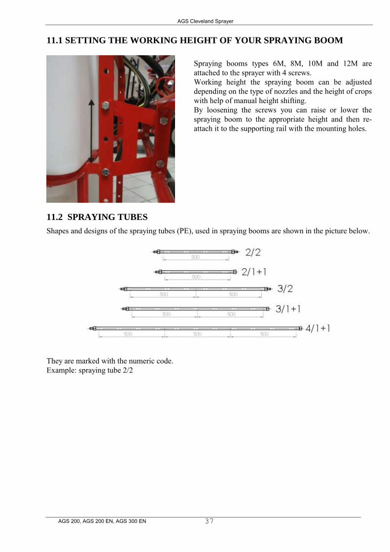
Spraying booms types 6M, 8M, 10M and 12M are attached to the sprayer with 4 screws. Working height the spraying boom can be adjusted depending on the type of nozzles and the height of crops with help of manual height shifting. By loosening the screws you can raise or lower the spraying boom to the appropriate height and then re-attach it to the supporting rail with the mounting holes.
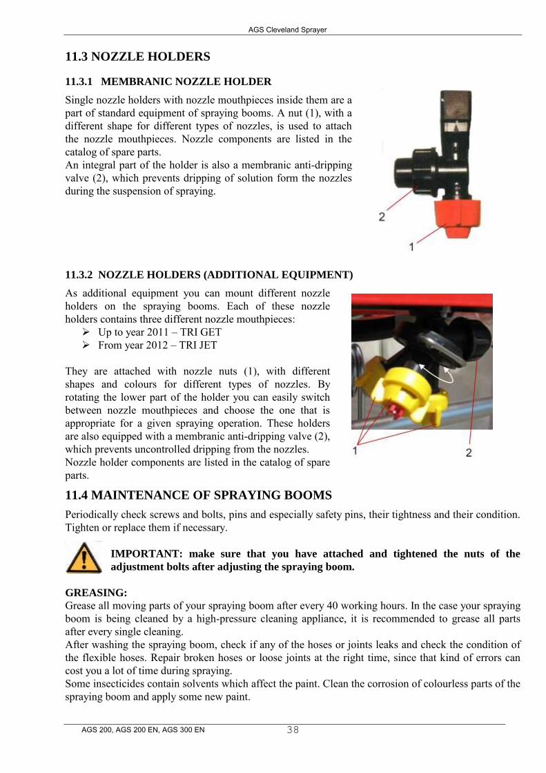
11.2 SPRAYING TUBES
Shapes and designs of the spraying tubes (PE), used in spraying booms are shown in the picture below. They are marked with the numeric code. Example: spraying tube 2/2
AGS Cleveland Sprayer
AGS 200, AGS 200 EN, AGS 300 EN
38
11.3 NOZZLE HOLDERS
11.3.1 MEMBRANIC NOZZLE HOLDER
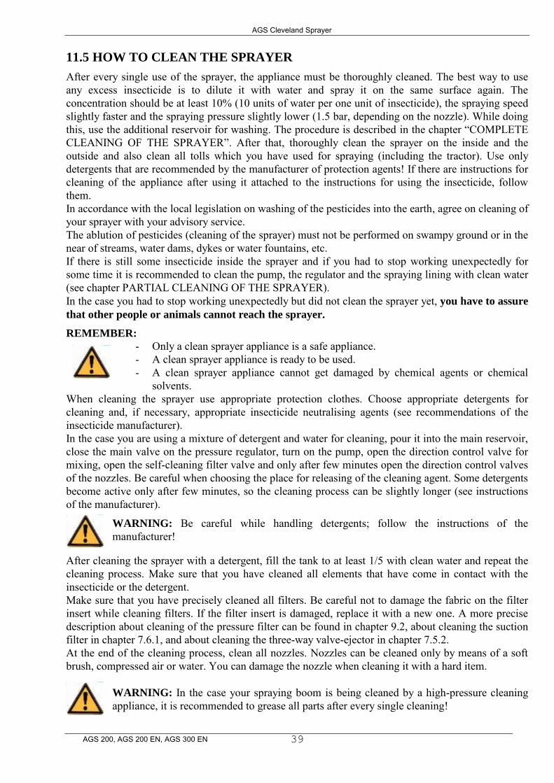
Single nozzle holders with nozzle mouthpieces inside them are a part of standard equipment of spraying booms. A nut (1), with a different shape for different types of nozzles, is used to attach the nozzle mouthpieces. Nozzle components are listed in the catalog of spare parts. An integral part of the holder is also a membranic anti-dripping valve (2), which prevents dripping of solution form the nozzles during the suspension of spraying.
11.3.2 NOZZLE HOLDERS (ADDITIONAL EQUIPMENT)
As additional equipment you can mount different nozzle holders on the spraying booms. Each of these nozzle holders contains three different nozzle mouthpieces:
Up to year 2011 – TRI GET From year 2012 – TRI JET
They are attached with nozzle nuts (1), with different shapes and colours for different types of nozzles. By rotating the lower part of the holder you can easily switch between nozzle mouthpieces and choose the one that is appropriate for a given spraying operation. These holders are also equipped with a membranic anti-dripping valve (2), which prevents uncontrolled dripping from the nozzles. Nozzle holder components are listed in the catalog of spare parts.
11.4 MAINTENANCE OF SPRAYING BOOMS
Periodically check screws and bolts, pins and especially safety pins, their tightness and their condition. Tighten or replace them if necessary.
IMPORTANT: make sure that you have attached and tightened the nuts of the
adjustment bolts after adjusting the spraying boom.
GREASING: Grease all moving parts of your spraying boom after every 40 working hours. In the case your spraying boom is being cleaned by a high-pressure cleaning appliance, it is recommended to grease all parts after every single cleaning. After washing the spraying boom, check if any of the hoses or joints leaks and check the condition of the flexible hoses. Repair broken hoses or loose joints at the right time, since that kind of errors can cost you a lot of time during spraying. Some insecticides contain solvents which affect the paint. Clean the corrosion of colourless parts of the spraying boom and apply some new paint.
AGS Cleveland Sprayer
AGS 200, AGS 200 EN, AGS 300 EN
39
11.5 HOW TO CLEAN THE SPRAYER
After every single use of the sprayer, the appliance must be thoroughly cleaned. The best way to use any excess insecticide is to dilute it with water and spray it on the same surface again. The concentration should be at least 10% (10 units of water per one unit of insecticide), the spraying speed slightly faster and the spraying pressure slightly lower (1.5 bar, depending on the nozzle). While doing this, use the additional reservoir for washing. The procedure is described in the chapter “COMPLETE CLEANING OF THE SPRAYER”. After that, thoroughly clean the sprayer on the inside and the outside and also clean all tolls which you have used for spraying (including the tractor). Use only detergents that are recommended by the manufacturer of protection agents! If there are instructions for cleaning of the appliance after using it attached to the instructions for using the insecticide, follow them. In accordance with the local legislation on washing of the pesticides into the earth, agree on cleaning of your sprayer with your advisory service. The ablution of pesticides (cleaning of the sprayer) must not be performed on swampy ground or in the near of streams, water dams, dykes or water fountains, etc. If there is still some insecticide inside the sprayer and if you had to stop working unexpectedly for some time it is recommended to clean the pump, the regulator and the spraying lining with clean water (see chapter PARTIAL CLEANING OF THE SPRAYER). In the case you had to stop working unexpectedly but did not clean the sprayer yet, you have to assure
that other people or animals cannot reach the sprayer.
REMEMBER:
- Only a clean sprayer appliance is a safe appliance. - A clean sprayer appliance is ready to be used. - A clean sprayer appliance cannot get damaged by chemical agents or chemical
solvents. When cleaning the sprayer use appropriate protection clothes. Choose appropriate detergents for cleaning and, if necessary, appropriate insecticide neutralising agents (see recommendations of the insecticide manufacturer). In the case you are using a mixture of detergent and water for cleaning, pour it into the main reservoir, close the main valve on the pressure regulator, turn on the pump, open the direction control valve for mixing, open the self-cleaning filter valve and only after few minutes open the direction control valves of the nozzles. Be careful when choosing the place for releasing of the cleaning agent. Some detergents become active only after few minutes, so the cleaning process can be slightly longer (see instructions of the manufacturer).
WARNING: Be careful while handling detergents; follow the instructions of the manufacturer!
After cleaning the sprayer with a detergent, fill the tank to at least 1/5 with clean water and repeat the cleaning process. Make sure that you have cleaned all elements that have come in contact with the insecticide or the detergent. Make sure that you have precisely cleaned all filters. Be careful not to damage the fabric on the filter insert while cleaning filters. If the filter insert is damaged, replace it with a new one. A more precise description about cleaning of the pressure filter can be found in chapter 9.2, about cleaning the suction filter in chapter 7.6.1, and about cleaning the three-way valve-ejector in chapter 7.5.2. At the end of the cleaning process, clean all nozzles. Nozzles can be cleaned only by means of a soft brush, compressed air or water. You can damage the nozzle when cleaning it with a hard item.
WARNING: In the case your spraying boom is being cleaned by a high-pressure cleaning appliance, it is recommended to grease all parts after every single cleaning!

AGS Cleveland Sprayer
AGS 200, AGS 200 EN, AGS 300 EN
40
11.6 MAINTENANCE AND STORAGE AFTER USE
When the spraying season is over, find some time and prepare the spraying appliance for storage. Before storing the appliance, thoroughly clean the inside and the outside of the sprayer (regulator, pump, sieves, selection valves, nozzles, etc.). When the cleaning is done make sure that there is no water left in the valves, the filters, the pump, the nozzles, etc. Do not maintain the sprayer until it has not been thoroughly cleaned.
11.6.1 HOSES
Check the tightness of all hoses and hose junctions. Replace damaged hoses with new ones. A damaged hose cost you a lot of time during spraying.
11.6.2 PAINT
Some insecticides contain solvents which affect the paint. Clean the corrosion of colourless parts of the spraying appliance and apply some new paint.
11.6.3 RESERVOIR
Make sure that there are no rests of insecticide inside the reservoir. Chemical agents must not stay in the reservoir for al long time, since they can fast shorten the durability of the reservoir and other parts. Make sure that the outflow valve is opened.
11.6.4 PRESSURE REGULATOR
Protect the pressure regulator against moisture and dust. It is recommended to grease moving parts with WD-40 or oil. There are further instructions about the maintenance of the regulator in chapter "MAINTENANCE OF THE REGULATOR".
11.6.5 PUMP
After every season, thoroughly clean the inside and the outside of the pump and prepare it for storage. Check the quantity of working hours and, if necessary, repair the pump (oil change, membrane change, sealing change, etc) or at least check the oil level, the sealing, etc. This is the most appropriate time of the season to perform some maintenance work. If you are not sure whether or not you can repair the pump on your own, leave the work to an authorized expert. You can find the description about maintenance work in the chapter "PUMPS".
11.6.6 DRIVE SHAFT-CARDAN
It is very important that the safety pin, which is attached to the head of the cardan shaft, is clean and greased. This assures that the shaft is safe to use. Check the protective cover, the functioning and the condition of the cardan shaft every 40 working hours. Replace damaged parts with new ones. Check the protective cover of the cardan shaft every 100 working hours and, if necessary, replace the sliding plates of the protection. Also check the condition of the cardan shaft. Pay special attention to the safety pin. Replace damaged parts with new ones.
11.6.7 BOLTS
IMPORTANT: Check the bolts, pins and especially safety pins, their tightness and their condition. If necessary, tighten or replace them.
AGS Cleveland Sprayer
AGS 200, AGS 200 EN, AGS 300 EN
41
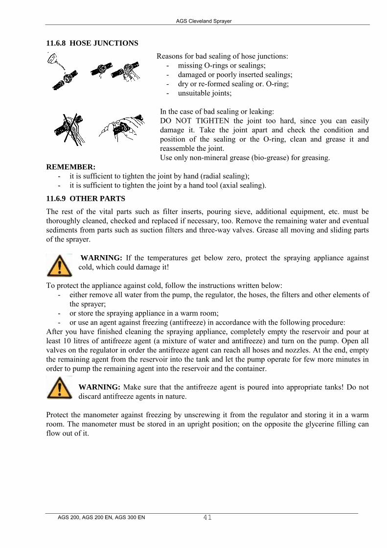
11.6.8 HOSE JUNCTIONS
Reasons for bad sealing of hose junctions: - missing O-rings or sealings; - damaged or poorly inserted sealings; - dry or re-formed sealing or. O-ring; - unsuitable joints;
In the case of bad sealing or leaking: DO NOT TIGHTEN the joint too hard, since you can easily damage it. Take the joint apart and check the condition and position of the sealing or the O-ring, clean and grease it and reassemble the joint. Use only non-mineral grease (bio-grease) for greasing.
REMEMBER:
- it is sufficient to tighten the joint by hand (radial sealing); - it is sufficient to tighten the joint by a hand tool (axial sealing).
11.6.9 OTHER PARTS
The rest of the vital parts such as filter inserts, pouring sieve, additional equipment, etc. must be thoroughly cleaned, checked and replaced if necessary, too. Remove the remaining water and eventual sediments from parts such as suction filters and three-way valves. Grease all moving and sliding parts of the sprayer.
WARNING: If the temperatures get below zero, protect the spraying appliance against cold, which could damage it!
To protect the appliance against cold, follow the instructions written below: - either remove all water from the pump, the regulator, the hoses, the filters and other elements of
the sprayer; - or store the spraying appliance in a warm room; - or use an agent against freezing (antifreeze) in accordance with the following procedure:
After you have finished cleaning the spraying appliance, completely empty the reservoir and pour at least 10 litres of antifreeze agent (a mixture of water and antifreeze) and turn on the pump. Open all valves on the regulator in order the antifreeze agent can reach all hoses and nozzles. At the end, empty the remaining agent from the reservoir into the tank and let the pump operate for few more minutes in order to pump the remaining agent into the reservoir and the container.
WARNING: Make sure that the antifreeze agent is poured into appropriate tanks! Do not discard antifreeze agents in nature.
Protect the manometer against freezing by unscrewing it from the regulator and storing it in a warm room. The manometer must be stored in an upright position; on the opposite the glycerine filling can flow out of it.
AGS Cleveland Sprayer
AGS 200, AGS 200 EN, AGS 300 EN
42
12 POSSIBLE ERRORS
SIGNS FOR
ERROR
POSSIBLE REASON CHECK / REPAIR
There is no liquid coming out from the nozzles even though the main valve on the flow regulator is opened.
- damaged or incorrectly inserted valves in the pump;
- closed manual valve on the suction side;
- the suction or pressure filter is clogged;
- there is some air inside the suction line.
- check and if necessary replace valves in the pump;
- check the valves on the suction
line to the pump; - clean or replace the filter insert; - check the tightness of the hose
junctions on the suction side.
The insecticide jet is unsymmetrical.
- inappropriate pressure in the air chamber.
- check the air pressure in the air chamber and fill it according to the data from chapter 11.1.
The pressure is falling according to the manometer; the working pressure can not be reached.
- the suction or pressure filter is clogged;
- the pressure hose is broken;
- the valve of the self-cleaning filter is opened;
- incorrectly chosen or too worn nozzle inserts;
- clean or replace the filter insert; - replace the hose; - close the valve of the self-cleaning
filter; - check the flow rate through the
nozzles – if it is bigger than 10%, replace the nozzles;
The pressure on the manometer is strongly swinging.
- there is some air inside the suction line;
- the membranes are damaged.
- check the tightness of the hose junctions on the suction side;
- stop the pump immediately; - replace the membranes and the oil
inside the pump; The pump is noisy. - too low oil level;
- exceeded maximum rpm
- control the oil level and add some if necessary;
- control the rpm of the pump. There is some insecticide in the oil of the pump.
- damaged membranes. - stop the pump immediately; - replace the membranes and the oil
inside the pump; - before mounting new membranes,
thoroughly clean the inside of the pump with diesel oil.
AGS Cleveland Sprayer
AGS 200, AGS 200 EN, AGS 300 EN
45
13.7 MEASUREMENT OF LIQUID FLOW RATE THROUGH THE NOZZLE
To measure the liquid flow rate through the nozzle, you will need a piece of soft flexible hose with an inner diameter of 25 mm or 1” and an appropriate container (it is recommended to use a measuring cylinder). Simply put on the hose on the nozzle and measure the liquid flow rate by catching the liquid of individual nozzles into the measuring cylinder. You will also need a stopwatch or a wristwatch. The measurement time is one minute. If you have performed the measurement in less than one minute, calculate the liquid flow rate to one minute. If the liquid flow rate of a nozzle at a specific pressure exceeds the table values for more than 10% than the nozzle insert is worn and needs to be replaced.
13.8 DISPOSAL OF THE SPRAYER
Once the spraying appliance can not be used anymore, you will have to clean it completely, take it apart and sort the individual components of the sprayer by material. The components must be handed over to an organisation which deals with waste materials. The reservoir and other plastic parts of the sprayer can be recycled or burned in special incineration sites. The metal parts can be sorted out as scrap metal. Consider the local legislation for waste materials.
13.9 MATERIALS AND RECYCLING
RESERVOIR…..PE HD (polyethylene of high density)
13.10 FLEXIBLE HOSES…..RUBBER, PVC
FRAME …..STEEL VALVES, REGULATOR, NOZZLE HOLDERS ….. more or less PA with fibre glass NOZZLE HOLDER HOSES …..PE (polyethylene)
AGS Cleveland Sprayer
AGS 200, AGS 200 EN, AGS 300 EN
46
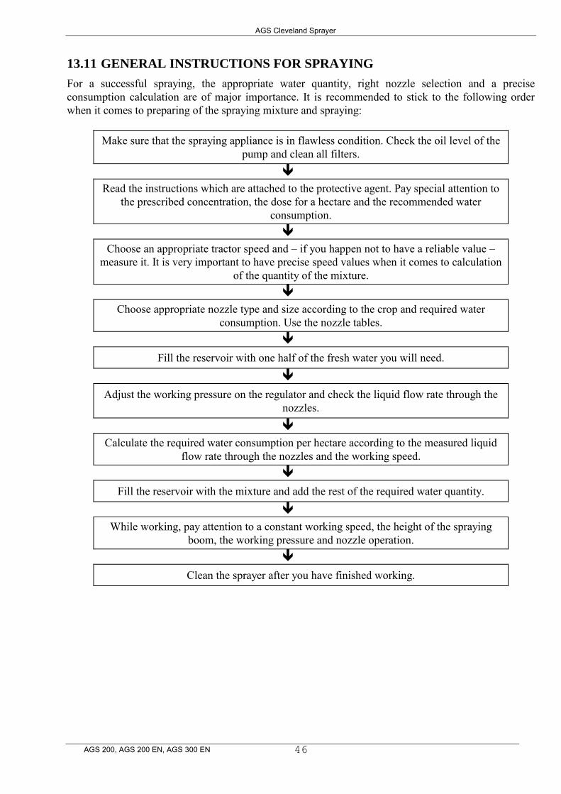
13.11 GENERAL INSTRUCTIONS FOR SPRAYING
For a successful spraying, the appropriate water quantity, right nozzle selection and a precise consumption calculation are of major importance. It is recommended to stick to the following order when it comes to preparing of the spraying mixture and spraying:
Make sure that the spraying appliance is in flawless condition. Check the oil level of the pump and clean all filters.
Read the instructions which are attached to the protective agent. Pay special attention to the prescribed concentration, the dose for a hectare and the recommended water
consumption.
Choose an appropriate tractor speed and – if you happen not to have a reliable value – measure it. It is very important to have precise speed values when it comes to calculation
of the quantity of the mixture.
Choose appropriate nozzle type and size according to the crop and required water consumption. Use the nozzle tables.
Fill the reservoir with one half of the fresh water you will need.
Adjust the working pressure on the regulator and check the liquid flow rate through the nozzles.
Calculate the required water consumption per hectare according to the measured liquid flow rate through the nozzles and the working speed.
Fill the reservoir with the mixture and add the rest of the required water quantity.
While working, pay attention to a constant working speed, the height of the spraying boom, the working pressure and nozzle operation.
Clean the sprayer after you have finished working.
AGS Cleveland Sprayer
AGS 200, AGS 200 EN, AGS 300 EN
47
14 TYPES OF NOZZLES IN AGRICULTURE
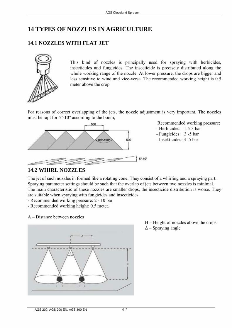
14.1 NOZZLES WITH FLAT JET
This kind of nozzles is principally used for spraying with herbicides, insecticides and fungicides. The insecticide is precisely distributed along the whole working range of the nozzle. At lower pressure, the drops are bigger and less sensitive to wind and vice-versa. The recommended working height is 0.5 meter above the crop.
For reasons of correct overlapping of the jets, the nozzle adjustment is very important. The nozzles must be rapt for 5°-10° according to the boom,
Recommended working pressure: - Herbicides: 1.5-3 bar - Fungicides: 3 -5 bar - Insekticides: 3 -5 bar
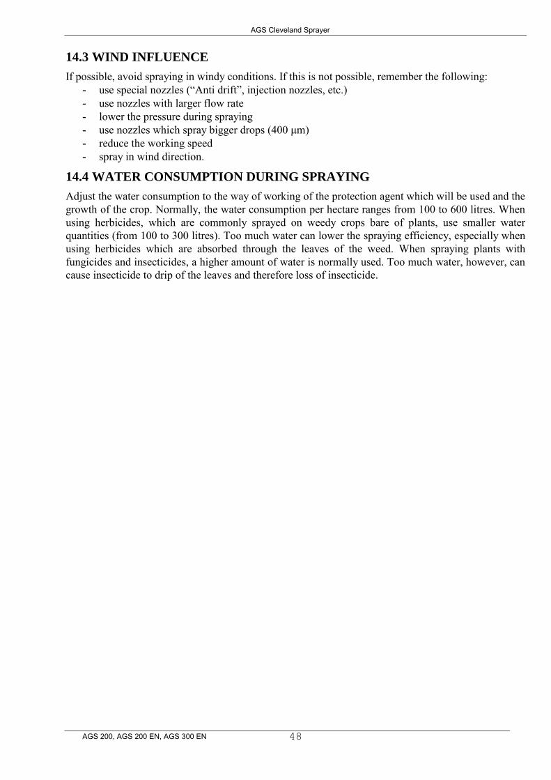
14.2 WHIRL NOZZLES
The jet of such nozzles in formed like a rotating cone. They consist of a whirling and a spraying part. Spraying parameter settings should be such that the overlap of jets between two nozzles is minimal. The main characteristic of these nozzles are smaller drops, the insecticide distribution is worse. They are suitable when spraying with fungicides and insecticides. - Recommended working pressure: 2 - 10 bar - Recommended working height: 0.5 meter.
A – Distance between nozzles H – Height of nozzles above the crops Δ – Spraying angle
AGS Cleveland Sprayer
AGS 200, AGS 200 EN, AGS 300 EN
48
14.3 WIND INFLUENCE
If possible, avoid spraying in windy conditions. If this is not possible, remember the following: - use special nozzles (“Anti drift”, injection nozzles, etc.) - use nozzles with larger flow rate - lower the pressure during spraying - use nozzles which spray bigger drops (400 μm) - reduce the working speed - spray in wind direction.
14.4 WATER CONSUMPTION DURING SPRAYING
Adjust the water consumption to the way of working of the protection agent which will be used and the growth of the crop. Normally, the water consumption per hectare ranges from 100 to 600 litres. When using herbicides, which are commonly sprayed on weedy crops bare of plants, use smaller water quantities (from 100 to 300 litres). Too much water can lower the spraying efficiency, especially when using herbicides which are absorbed through the leaves of the weed. When spraying plants with fungicides and insecticides, a higher amount of water is normally used. Too much water, however, can cause insecticide to drip of the leaves and therefore loss of insecticide.
AGS Cleveland Sprayer
AGS 200, AGS 200 EN, AGS 300 EN
49
15 TABLES
TABLE 1: Flow rate of spraying nozzles type LECHLER (v l/min):
REMARK: THE NOZZLE FLOW RATES ARE ALWAYS THE SAME FOR
THE SAME COLOUR MARKINGS OF DIFFERENT TYPES (ST, LU, AD, ID,
TR, ETC.) AND NOZZLE MATERIALS.
NUMBER: NOZZLE
TYPE:
NOZZLE
COLOUR: WORKING PRESSURE (bar)
2,0 2,5 3,0 3,5 4,0 4,5 5,0 110015 GREEN 0,48 0,53 0,59 0,63 0,68 0,72 0,76
019.48.062 11002 YELLOW 0,63 0,71 0,78 0,85 0,90 0,96 1,01 019.48.063 11003 BLUE 0,95 1,06 1,17 1,26 1,35 1,44 1,52 019.48.064 11004 RED 1,26 1,42 1,55 1,68 1,80 1,91 2,02 019.48.065 11005 BROWN 1,57 1,77 1,94 2,10 2,25 2,39 2,48 019.48.066 11006 GREY 1,88 2,11 2,32 2,51 2,69 2,86 3,01 019.48.067 11008 WHITE 2,50 2,81 3,08 3,33 3,57 3,79 4,00
TABLE 2: Liquid consumption per hectare (l/ha) according to the flow rate of the nozzle (l/min) and working speed (km/h) – applies only to spraying booms with 0.5 meter distance between the nozzles:
WORKING SPEED (km/h) l/min 3,0 3,5 4,0 4,5 4,8 5,0 5,2 5,4 5,6 5,8 6,0 6,5 7,0 0,50 200 171 150 133 125 120 115 111 107 103 100 92 86 0,60 240 205 180 160 150 144 138 133 128 124 120 110 103 0,70 280 240 210 187 175 168 162 156 150 145 140 129 120 0,80 320 274 240 213 200 192 185 178 171 165 160 148 137 0,90 360 309 270 240 225 216 208 200 193 186 180 166 154 1,00 400 343 300 266 250 240 231 222 214 207 200 185 171 1,10 440 377 330 293 275 264 254 244 236 228 220 203 188 1,20 480 411 360 320 300 288 277 267 257 248 240 222 206 1,30 520 446 390 347 325 312 300 289 278 269 260 240 223 1,40 560 480 420 373 350 336 323 311 300 290 280 258 240 1,50 600 514 450 400 375 360 346 333 321 310 300 277 257 1,60 640 549 480 427 400 384 369 355 343 331 320 295 274 1,70 680 583 510 453 425 408 392 378 364 352 340 314 291 1,80 720 617 540 480 450 432 415 400 386 372 360 332 309 1,90 760 651 570 507 475 456 438 422 407 393 380 350 325 2,00 800 685 600 533 500 480 461 444 428 413 400 369 342 2,10 840 720 630 560 525 504 484 466 540 434 420 387 360 2,20 880 754 660 586 550 528 507 488 471 455 440 406 377 2,30 920 788 690 613 575 552 530 511 492 575 460 424 394 2,40 960 822 720 640 600 576 553 533 514 496 480 443 411 2,50 857 750 666 625 600 577 555 535 517 500 461 428 2,60 891 780 693 650 624 600 577 557 537 520 480 445 2,70 925 810 720 675 648 623 600 578 558 540 598 463 2,80 960 840 746 700 672 646 622 600 579 560 517 480 2,90 994 870 773 725 696 669 644 621 600 580 535 497 3,00 900 800 750 720 692 666 643 620 600 554 514
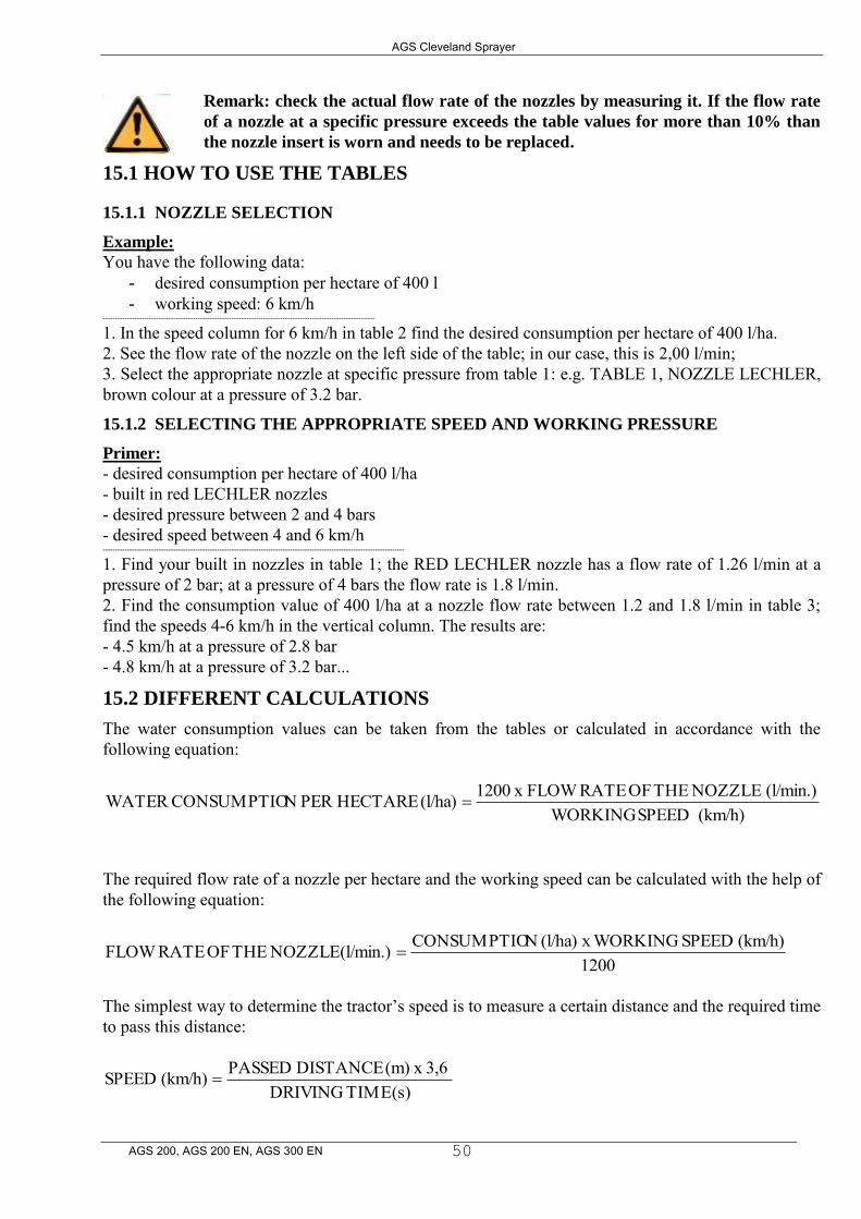
AGS Cleveland Sprayer
AGS 200, AGS 200 EN, AGS 300 EN
50
Remark: check the actual flow rate of the nozzles by measuring it. If the flow rate
of a nozzle at a specific pressure exceeds the table values for more than 10% than
the nozzle insert is worn and needs to be replaced.
15.1 HOW TO USE THE TABLES
15.1.1 NOZZLE SELECTION
Example:
You have the following data: - desired consumption per hectare of 400 l - working speed: 6 km/h
----------------------------------------------------------------------------------------------------------------
1. In the speed column for 6 km/h in table 2 find the desired consumption per hectare of 400 l/ha. 2. See the flow rate of the nozzle on the left side of the table; in our case, this is 2,00 l/min; 3. Select the appropriate nozzle at specific pressure from table 1: e.g. TABLE 1, NOZZLE LECHLER, brown colour at a pressure of 3.2 bar.
15.1.2 SELECTING THE APPROPRIATE SPEED AND WORKING PRESSURE
Primer: - desired consumption per hectare of 400 l/ha - built in red LECHLER nozzles - desired pressure between 2 and 4 bars
- desired speed between 4 and 6 km/h ----------------------------------------------------------------------------------------------------------------------------
1. Find your built in nozzles in table 1; the RED LECHLER nozzle has a flow rate of 1.26 l/min at a pressure of 2 bar; at a pressure of 4 bars the flow rate is 1.8 l/min. 2. Find the consumption value of 400 l/ha at a nozzle flow rate between 1.2 and 1.8 l/min in table 3; find the speeds 4-6 km/h in the vertical column. The results are: - 4.5 km/h at a pressure of 2.8 bar - 4.8 km/h at a pressure of 3.2 bar...
15.2 DIFFERENT CALCULATIONS
The water consumption values can be taken from the tables or calculated in accordance with the following equation:
(km/h) SPEEDWORKING (l/min.) NOZZLE THE OF RATEFLOW x 1200(l/ha) HECTARE PER NCONSUMPTIO WATER
The required flow rate of a nozzle per hectare and the working speed can be calculated with the help of the following equation:
1200(km/h) SPEED x WORKING(l/ha) NCONSUMPTIO(l/min.) NOZZLE THE OF RATEFLOW
The simplest way to determine the tractor’s speed is to measure a certain distance and the required time to pass this distance:
(s) TIMEDRIVING 3,6 x (m) DISTANCE PASSED(km/h) SPEED
