aggrandizing and analysis of the adaptability of ... · (lm35, texas instruments) dc motor (17v,...
TRANSCRIPT

* Corresponding author. Tel: +919981496253 E-mail addresses: [email protected] (A. Ranjan) © 2016 Growing Science Ltd. All rights reserved. doi: 10.5267/j.esm.2015.12.002
Engineering Solid Mechanics 4 (2016) 69-80
Contents lists available at GrowingScience
Engineering Solid Mechanics
homepage: www.GrowingScience.com/esm
Aggrandizing and analysis of the adaptability of photovoltaic panels
Anurag Ranjana*, Ira Bhatnagarb, Kavita Prajapatic
aDepartment of Mechanical Engineering, Institute of Technology and Management , Gwalior, India bDepartment of Electronic & Communication Engineering, Institute of Technology and Management, Gwalior, India cDepartment of Electronic & Communication Engineering, Institute of Technology and Management, Gwalior, India
A R T I C L E I N F O A B S T R A C T
Article history: Received 6 September, 2015 Accepted 4 December 2015 Available online 4 December 2015
The use of solar energy has been adduced as an alternative way for generating electricity. This electricity is generated by solar panel but as temperature increases efficiency of panel decreases too. The main objective of this research paper is to minimize the use of the amount of water, electrical energy and required time needed for cooling of a solar panel. This paper discusses a new approach by acquiring water as a coolant for accomplishing Photovoltaic panels at their moderate temperature and limits it from overheating. It is the cheapest method to enhance the efficiency of the Photovoltaic panel in developing countries like India. This paper also analyses the material used in increasing the efficiency of PV panel.
© 2016 Growing Science Ltd. All rights reserved.
Keywords: Alternative Cooling Overheating Photovoltaic panel Efficiency Analyses
1. Introduction
“The development of affordable, inexhaustible and clean solar energy technologies will have huge longer-term benefits. It will increase countries’ energy security through reliance on an indigenous, inexhaustible and mostly import-independent resource, enhance sustainability, reduce pollution, lower the costs of mitigating global warming, and keep fossil fuel prices lower than otherwise. These advantages are global. Hence the additional costs of the incentives for early deployment should be considered learning investments; they must be wisely spent and need to be widely shared”– said by “International Energy Agency “. Photovoltaic (PV) panel is the best way for producing electricity from solar energy. But PV panels are affected by their operating temperatures, which are primarily a product of the ambient temperature as well as the level of sunlight. Overheating due to excessive solar radiation and high ambient temperatures reduces the efficiency of the panels dramatically (Rai, 1992; Garg & Prakash, 2006). Experimental value of temperature coefficient which is given in the characteristic data of a PV panel indicates the decrement in the efficiency of the panel per degree increase in the temperature. The temperature coefficient of the PV panels used in this research is -0.5%/°C, which

70
indicates that every 1°C of temperaturerisecorrespondstoadropinthe efficiency by 0.5% (Moharram et al., 2013). This indicates that heating of the PV panels can affect the output of the panels significantly. Fig. 1 shows Power (P) versus voltage (V) characteristic function graph of a PV panel which show how voltage is getting low with increase in the temperature.
Fig. 1. P–V characteristics as a function of the module temperature. The module temperature varies
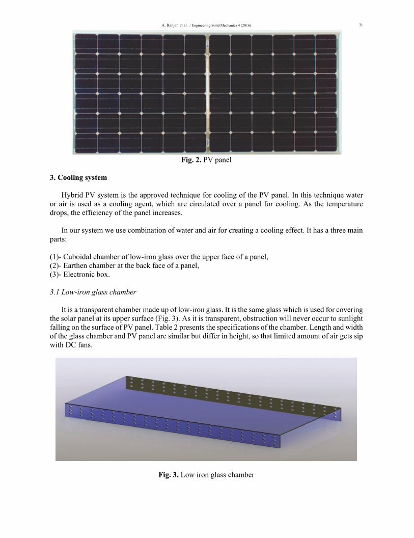
between 0°C and 75°C Here we develop a system which reduces the temperature of a panel in case of overheating and maintains it at normal working temperature. Also the effect of material used in this cooling system of PV panel is analyzed. 2. Solar panel The BP 7185N photovoltaic panel shown in Fig. 2 is used for the analysis in this paper. The BP 7185N has been especially designed for grid connect applications such as large commercial roofs, residential systems and photovoltaic power plants. Table 1 presents characteristics of the investigated panel. Table 1. Characteristics of a panel Electrical characteristics
Mechanical characteristics Solar cells 72 monocrystalline cells (125mm x125mm) connected in series.
Front cover High transmission 3.2mm. Tempered anti reflective coated glass
Dimensions (mm) 1593±3 x 790±3 x 50
Weight (kg) 15.4
Maximum power (Pmax) 185W Voltage at MPP (Vmpp) 36.0V Current at MPP (Impp) 5.1A Short circuit current (Isc) 5.4A Open circuit voltage (Voc) 44.2V Temperature coefficient of Isc (0.065±0.015)%/K
Temperature coefficient of Voc -(0.36±0.05)%/K Temperature coefficient of P -(0.5±0.05)%/K
A. Ranjan et al. / Engineering Solid Mechanics 4 (2016)
71
Fig. 2. PV panel
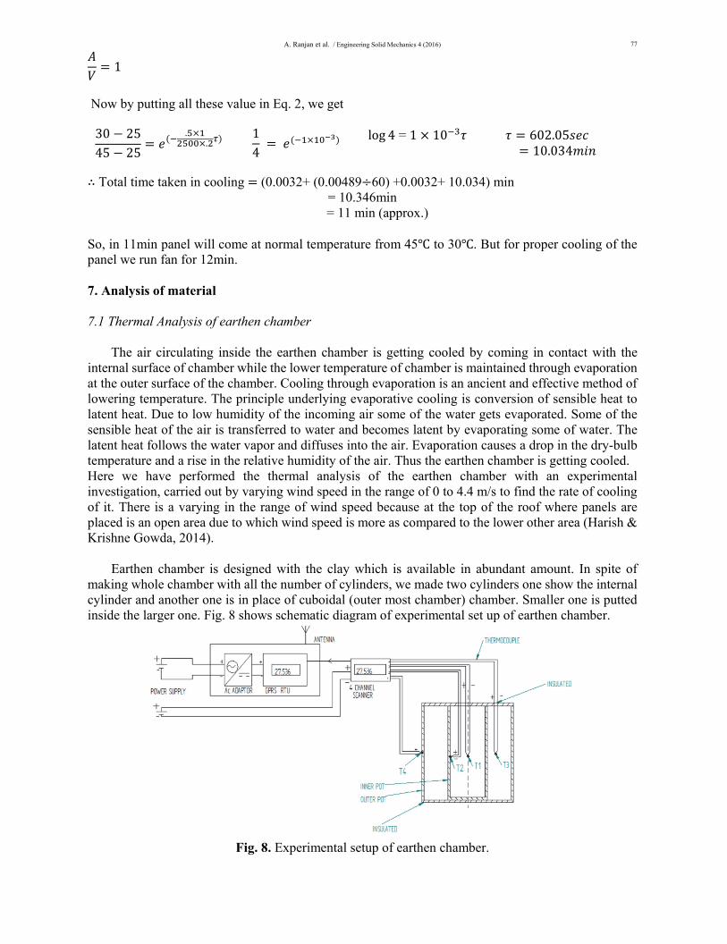
3. Cooling system Hybrid PV system is the approved technique for cooling of the PV panel. In this technique water or air is used as a cooling agent, which are circulated over a panel for cooling. As the temperature drops, the efficiency of the panel increases. In our system we use combination of water and air for creating a cooling effect. It has a three main parts: (1)- Cuboidal chamber of low-iron glass over the upper face of a panel, (2)- Earthen chamber at the back face of a panel, (3)- Electronic box. 3.1 Low-iron glass chamber It is a transparent chamber made up of low-iron glass. It is the same glass which is used for covering the solar panel at its upper surface (Fig. 3). As it is transparent, obstruction will never occur to sunlight falling on the surface of PV panel. Table 2 presents the specifications of the chamber. Length and width of the glass chamber and PV panel are similar but differ in height, so that limited amount of air gets sip with DC fans.
Fig. 3. Low iron glass chamber

72
Table 2. Properties and dimension of the low iron glass chamber Glass thickness 3.2mm Light transmittance 91.6% Specific heat 0.2 Density 2.5 g/cc Young modulus 73GPa Tensile strength 42 MPa Expansion coefficient 9.03 10-6/ Dimension (1593 790 150)mm3
Dimension of side hole D= 20mm 3.1.1 DC fan The chamber contains a DC exhaust fan “modal ZHGF-D04” of low voltage which forces hot air to flow in a lower chamber and later sucks the cold air again from the other side. The specifications of DC fan have been presented in Table 3.This will make a linear flow cycle of air, which cools the upper surface of the PV panel. Table 3. Characteristics of the DC fan Electric current type DC
Blade material Plastic
Voltage 17V
Power 5W
Air volume 1400
Speed 1600 rpm Air flow 3500 m3/hr
3.1.2. Elimination of greenhouse effect When glass chamber is closed, it will create the problem of greenhouse inside. For the elimination of this we provided small holes on its side walls so that, air will also flow from that holes and this will eliminate the chance of greenhouse. 3.2 Earthen chamber It is the most important part of a system fitted below the lower surface of PV panel. In this section water is kept which is used as a coolant. It will exactly work as an ancient earthen pot which is used to keep water cool in earlier decades (Mittal et al., 2006). It has the same dimension as of low iron glass chamber. But it does not have any hole on its side walls. Inside it, a number of cylinders, made up of earthen material are present for containing water which makes its wall cool (see Fig. 4). Lower surface of this part is having another flat chamber of little thickness. This section also contains water to make base at low temperature. Assembly of earthen chamber and its upper cover has been shown in Fig. 5.

A. Ranjan et al. / Engineering Solid Mechanics 4 (2016)
73
Fig. 4. Earthen chamber without upper cover Fig. 5. Earthen chamber with upper cover All these cylinders and lower chamber are connected through a pipe for filling of water. In India almost 80-85% of houses use water tanks on their roof. In which water supply is coming twice in a day. If we connect a pipe with that tank then there is no need of filling chamber manually. Dimension of it also is the same as the low iron glass chamber but its thickness is little more than upper chamber. It has 9 cylinders in a row and 3 in a column. So, total number of cylinder is 27. 3.3 Electronic circuit The foremost purpose of this electronic circuit is to run the DC motor automatically for 12min when the 45 temperature is achieved. Circuit also regulates the supply from PV panel to run the DC fan (17V, 5W) for cooling so there will be no need of external supply. This circuit consists of the following items:
Lm35 (RTD). (LM35, Texas instruments)
DC motor (17V, 5W)
AT89C51 microcontroller
LM358 op-amp comparator
RED LED (D1)
NPN- transistor (BD 139)
From the earlier data, we found that as the atmospheric temperature reaches to 25 , the efficiency of PV panel starts decreasing but in hot summer month, temperature of the environment becomes around 45 . Thus, we make fan to work at 45 .
Since the supply from the PV panel is fixed (i.e. 36V (B1)) and as the DC motor operates on 17V, we used an 18V (B2, 1V internal voltage drop) supply and 3.51ohm resistor for drop. The NPN transistor Q1 (BD- 139) is used for the switching purpose for turning on the dc motor for 12min.
3.3.1 Calculation of circuit
PV supply: - Voltage =36V, Power = 185watts
Since, P = VI
Total current from = = = 5.138 A
Current through DC motor = = = 294.12mA = 0.29412A
Since, motor and R are in parallel, voltage across R will be also 17V

74
Current through it = (total current – current through dc motor) = 5.138- .29412 = 4.84A
Value of R= = 17 4.84 = 3.51ohm.
Fig. 6 (a) and Fig. 6 (b) show the circuit when the fan is off and on, respectively.
(a) (b)
Fig. 6. Circuit when fan is (a) not working and (b) fan is on
As soon as the temperature reaches to 45 , the LM35(RTD) will sense the temperature, and when the 3 and 2 terminals voltages of LM358 becomes equal, then the output(terminal 1) goes HIGH (i.e. logic 1) and RED LED will glow which shows that DC fan will run for 12min. After 12min as the temperature panel reaches 30 , fan gets stopped and again cycle will get continue when panel temperature again reaches 45 .
4. Assembly of the cooling system
While doing an assembly of system, we have to give only two linear passages for incoming and outgoing of cold and hot air in the upper chamber, respectively. Both passages must be in the same axis. So that air will move in proper manner. Now low-iron chamber is fitted on the upper face of PV panel and on the back face earthen chamber. Earthen base and the glass chamber are open from both sides which are closed with a semi-cylindrical structure made up of glass fiber having very low thermal conductivity. DC fan is placed at one side of it. In lower part, near earthen chamber electronic box is fitted for keeping box cool and wires will take off internally up to the upper face for sensing a temperature. DC fan connection is also making through that board only. Fig. 7 shows the parts of cooling system and its assembly.
(a) (b)
Fig. 7. (a) Different parts of system before assembling and (b) the assembly of cooling system

A. Ranjan et al. / Engineering Solid Mechanics 4 (2016)
75
5. Working of system The most important part is associated with working of this cooling system. After we assemble it, it is ready for use. As we put PV panel under the sunlight and temperature get rises above 25°C, panel cooling system will not response quickly. It will make a sense and respond at a temperature for which microcontroller is programmed. When temperature of the surrounding increases, there is a comparatively fall in the voltage. As microcontroller is programmed for 45°C so when panel reached at this temperature, RTD acts at this and makes microcontroller to respond. Due to this DC fan gets start which suck hot air from the upper chamber and sends it to earthen chamber (lower chamber). Due to semi-cylindrical structure of fiber glass the air moves directly towards the lower chamber without going in any other direction. Where it is getting cooled and again comes up from another way. This cycle will continue until panel will not come at normal temperature. This time duration of cooling of a panel is calculated mathematically, which is around 12min. So fan will run for 12min in which panel gets cooled. The staring and closing of fan are controlled by microcontroller. Thus we increase the adaptability of PV panels. Now as panel comes at nominal temperature and fan stops, initially air present in upper chamber is at lower temperature, but again it gets rise in temperature which tries to make panel heat up. Before external heat acts on the temperature of a panel, it has to heat up the cold air (which also contain moisture) present inside chamber. When temperature raises again, RTD acts and fan starts with the help of microcontroller for the same time duration i.e. 12min. thus cycles continues. 6. Mathematical calculation There is a summation of four times T1, T2, T3, and T4 to determine actual time for cooling of the panel. 1. Total time taken for removal of hot air from the upper chamber (T1) 2. Then time it require to exchange the heat (T2) 3. Time required filling up the upper chamber again by cold air (T3) 4. Final time required to cool the panel. (T4) For time T1: Length of the upper chamber 1593mm Width of the chamber 790mm Height of the chamber 150mm Volume of chamber (1.593 .79 .15) m3 0.18877m3
It is given in the characteristic of DC fan: Air flow rate 3500m3/hr So, 3500m3 air flow in 60min 1m3 air flow in (60 3500) min per m3 ∴ .18875m3 air flow in (60 .18875) 3500 .0032 min For time T2: For finding the time required for heat exchange from hot air to water surface, we can use the formula of unsteady state heat conduction (Kumar, 2015).

76
(1)
where, t final temperature of air 25 tw temperature of water 20 ti intial temperature of air 45 hw 5000w/m2k K 0.0271w/mk (at 45 )
1.127kg/m3
Cp 1.005kj/kgk Area of the surface in contact air 2(L h) + (L b)-(7 3 r2) + (2 rh 7 3) 2 1.593 .15) +2(1.593 .79) –(7 3. 079 ) 2 .079 .15 7 3 .4779 2.51694 .41174 1.5635 4.1466m2 Volume of the chamber in which air is filled for cooling 7 3 (1.593 .79 .15 . 079 .15 7 3 .12700
∴ 32.650
Now by using Eq. (1), we get 25 2045 20
.. .
15
. 5 .
0.00489
For time T3: Since, time taken to fill the chamber is same as time taken to empty the chamber. So its flow rate is equal. ∴ T1=T3 For time T4:
For this also we will use same formula of unsteady state of heat conduction (Kumar, 2015):
(2)
t= final temperature of panel= 30 ta= temperature of cold air= 25 ti= initial temperature of panel= 45 ha= 15w/m2k =2500kg/m3 Cp= .2 J/kg k Since the thickness of the glass plate of a panel is very small as compared to length and width so it is neglected. ∴
A. Ranjan et al. / Engineering Solid Mechanics 4 (2016)
77
1
Now by putting all these value in Eq. 2, we get 30 2545 25
..
14
log 4 = 1 10
602.05 10.034
∴ Total time taken in cooling (0.0032+ (0.00489 60) +0.0032+ 10.034) min
= 10.346min = 11 min (approx.)
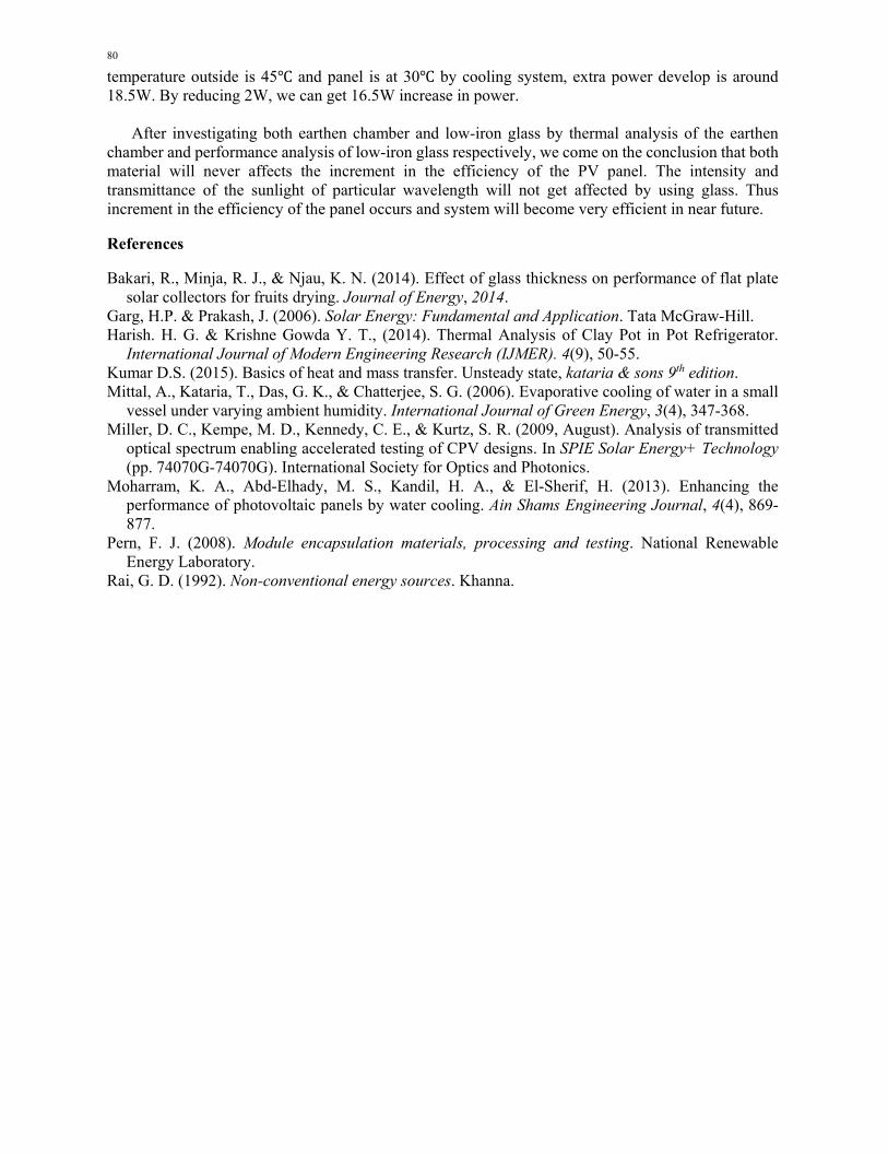
So, in 11min panel will come at normal temperature from 45 to 30 . But for proper cooling of the panel we run fan for 12min. 7. Analysis of material 7.1 Thermal Analysis of earthen chamber The air circulating inside the earthen chamber is getting cooled by coming in contact with the internal surface of chamber while the lower temperature of chamber is maintained through evaporation at the outer surface of the chamber. Cooling through evaporation is an ancient and effective method of lowering temperature. The principle underlying evaporative cooling is conversion of sensible heat to latent heat. Due to low humidity of the incoming air some of the water gets evaporated. Some of the sensible heat of the air is transferred to water and becomes latent by evaporating some of water. The latent heat follows the water vapor and diffuses into the air. Evaporation causes a drop in the dry-bulb temperature and a rise in the relative humidity of the air. Thus the earthen chamber is getting cooled. Here we have performed the thermal analysis of the earthen chamber with an experimental investigation, carried out by varying wind speed in the range of 0 to 4.4 m/s to find the rate of cooling of it. There is a varying in the range of wind speed because at the top of the roof where panels are placed is an open area due to which wind speed is more as compared to the lower other area (Harish & Krishne Gowda, 2014). Earthen chamber is designed with the clay which is available in abundant amount. In spite of making whole chamber with all the number of cylinders, we made two cylinders one show the internal cylinder and another one is in place of cuboidal (outer most chamber) chamber. Smaller one is putted inside the larger one. Fig. 8 shows schematic diagram of experimental set up of earthen chamber.
Fig. 8. Experimental setup of earthen chamber.

78
Fig. 8 shows the experimental setup of chamber for convection process. Here in this setup GPRS connected Remote Terminal Unit which has been used in experiment, monitors the analog inputs like temperature from various sensors and also does all the signal processing and digitizes the signal. We can view sensor wise analytic and graphs on centralized monitoring system using desktops, laptops, mobiles etc. Experiments are conducted and data’s are collected in the graphical form (Harish & Krishne Gowda, 2014). Experimental investigation is carried out by varying wind speed by 0, 2.6, 3.4 and 4.4 m/s. Tamp is for ambient temperature and T1 is for the temperature inside the chamber. From the graph presented in Fig. 9, it can be observed that rate of cooling is higher when the wind speed is 0 m/s and lower when wind speed is 4.4 m/s this is because of low rate of evaporation during low speed and high rate of evaporation during high speed of wind. As a result, temperature T1 is highest when wind speed is 0 m/s and lowest when wind speed is 4.4 m/s. At the roof air is always flowing with a speed and due to which temperature inside a chamber is maintain below 23 .
Fig. 9. Variation of temperature T1 with time at different wind speeds.
7.2 Performance analysis of the low-Iron PV glasses
By making a glass chamber over the PV panel, it is necessary to keep in mind that it does not affect the working ability of the panel. For this we did performance analysis of the low-iron glass. In this analysis we examined the performance like transmittance and energy rate capacity of the low-iron glass.
In the design for this experiment we made a solar collector which is covered with the low-iron glass. Similar flat plate solar collectors were used in this study; glazing material i.e. low iron (extra clear) glass of different thicknesses was used. Collectors were oriented to north south direction and tilted to an angle of 10° with the ground toward north direction. Collectors’ outlet temperatures were measured by using XR5-SE data logger connected with PT940 temperature sensors, whilst ambient temperatures were recorded by CEM DT-172 temperature and humidity data logger. Solar intensity and air flow rate were, respectively, measured by using PCE-SPM solar radiation meter and Testo 425 Hot Wire Thermal Anemometer. All collectors were placed at the top of a roof (Bakari et al., 2014). After the analysis result was plotted on the graph, shown in Fig. 10.

A. Ranjan et al. / Engineering Solid Mechanics 4 (2016)
79
Fig. 10. Energy rate with respect to variation in time
From Fig. 10, we can see that during the midday time energy transfer is high and not get affected by anything. After this experiment we come on the result that due to the upper chamber of low-iron glass no negative effects come on the efficiency of the PV panel. The energy rate is the same as previous condition during noon time. Fig. 11 also presents the results of transmittance-wavelength analysis. While investigating the transmittance percentage, at glass thickness of 3.2mm, in comparison with clear glass, we have concluded the result that it transmits 90% of the light falling on it, having wavelength greater than 360nm. And the visible sunlight wavelength is also lying above 350nm, so those upper chambers of glass also not affects the transmittance of light falling on it (Pern, 2008; Miller et al., 2009).
Fig. 11. Transmittance (%at 3.2mm glass) versus wavelength
8. Conclusion The main objective of this paper was to maintain the temperature of a PV panel by using the least amount of water and electricity and do analysis of two main materials used in it. Places like India where there is a great demand of electricity, this cooling system for panel is much more beneficial. This system works by using 5W of electricity if runs for 1h while it only runs for 12min in 1cycle. So its rate of cooling becomes 1.67 /min which is much more efficient. Whole set-up comes at very least cost. If system runs for 2 times in 1h, then it will consume 2W. This is very less energy consumptions. When
80
temperature outside is 45 and panel is at 30 by cooling system, extra power develop is around 18.5W. By reducing 2W, we can get 16.5W increase in power. After investigating both earthen chamber and low-iron glass by thermal analysis of the earthen chamber and performance analysis of low-iron glass respectively, we come on the conclusion that both material will never affects the increment in the efficiency of the PV panel. The intensity and transmittance of the sunlight of particular wavelength will not get affected by using glass. Thus increment in the efficiency of the panel occurs and system will become very efficient in near future. References Bakari, R., Minja, R. J., & Njau, K. N. (2014). Effect of glass thickness on performance of flat plate
solar collectors for fruits drying. Journal of Energy, 2014. Garg, H.P. & Prakash, J. (2006). Solar Energy: Fundamental and Application. Tata McGraw-Hill. Harish. H. G. & Krishne Gowda Y. T., (2014). Thermal Analysis of Clay Pot in Pot Refrigerator.
International Journal of Modern Engineering Research (IJMER). 4(9), 50-55. Kumar D.S. (2015). Basics of heat and mass transfer. Unsteady state, kataria & sons 9th edition. Mittal, A., Kataria, T., Das, G. K., & Chatterjee, S. G. (2006). Evaporative cooling of water in a small
vessel under varying ambient humidity. International Journal of Green Energy, 3(4), 347-368. Miller, D. C., Kempe, M. D., Kennedy, C. E., & Kurtz, S. R. (2009, August). Analysis of transmitted
optical spectrum enabling accelerated testing of CPV designs. In SPIE Solar Energy+ Technology (pp. 74070G-74070G). International Society for Optics and Photonics.
Moharram, K. A., Abd-Elhady, M. S., Kandil, H. A., & El-Sherif, H. (2013). Enhancing the performance of photovoltaic panels by water cooling. Ain Shams Engineering Journal, 4(4), 869-877.
Pern, F. J. (2008). Module encapsulation materials, processing and testing. National Renewable Energy Laboratory.
Rai, G. D. (1992). Non-conventional energy sources. Khanna.